

Page 1
®
PERMANENTLY LUBRICATED
TANK MOUNTED
AiR COMPRESSOR
• SAFETY GUiDELiNES
ASSEMBLY
OPERATION
MAINTENANCE
TROUBLESHOOTING
iMPORTANT:
Read the Safety Guidelines and
All instructions Carefully Before
Operating.
Sears, Roebuck and Co., Hoffman Estates, IL 60179 U.S.A.
MG2-OILFREE Rev. 7/26/99
Page 2
TABLE OF CONTENTS
Page
SAFETY GUIDELINES ................................................................................................................... 3
WARNING CHART ........................................................................................................................ 3
GLOSSARY ................................................................................................................................... 5
ACCESSORIES FOR USE WITH SEARS AIR COMPRESSORS ................................................... 5
GENERAL INFORMATION ............................................................................................................ 5
DESCRIPTION OF OPERATION .................................................................................................... 6
ASSEMBLY ................................................................................................................................... 6
INSTALLATION AND BREAK-IN PROCEDURES .......................................................................... 7
Location of Air Compressor .................................................................................................... 7
Lubrication and Oil .................................................................................................................. 7
Extension Cords ..................................................................................................................... 7
Voltage and Circuit Protection ................................................................................................ 7
Grounding Instructions ........................................................................................................... 7
Break-in Procedure ................................................................................................................. 8
OPERATING PROCEDURES ......................................................................................................... 8
MAINTENANCE ............................................................................................................................. 9
Air Filter - Inspection and Replacement .................................................................................. 9
Check Valve -Replacement .................................................................................................... 9
Safety Valve - Inspection ........................................................................................................ 9
Motor ...................................................................................................................................... 9
Storage ................................................................................................................................... 9
TROUBLESHOOTING GUIDE ...................................................................................................... 10
HOW TO ORDER REPAIR PARTS ............................................................................................... 14
WARRANTY ................................................................................................................................. 14
2
2
Page 3
iMPORTANT SAFETY iNSTRUCTiONS
" SAVE THESE INSTRUCTIONS "
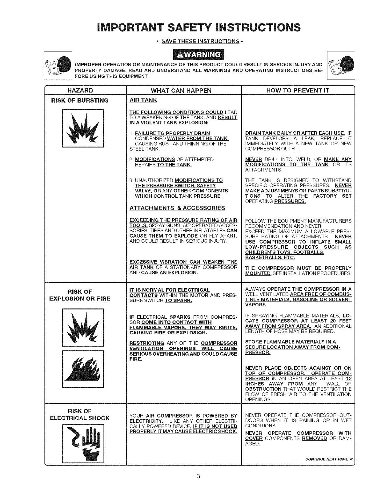
iMPROPER OPERATION OR MAINTENANCE OF THIS PRODUCT COULD RESULT IN SERIOUS INJURYAND
PROPERTY DAMAGE. READ AND UNDERSTAND ALL WARNINGS AND OPERATING INSTRUCTIONS BE-
FORE USING THIS EQUIPMENT.
HAZARD
RiSK OF BURSTING
r
E
L
WHAT CAN HAPPEN
AiR TANK
THE FOLLOWING CONDiTiONS COULD LEAD
TO A WEAKENING OF THE TANK, AND RESULT
iN A VIOLENT TANK EXPLOSION:
1. FAILURE TO PROPERLY DRAIN
CONDENSED WATER FROM THE TANK,
CAUSING RUST AND THINNING OF THE
STEEL TANK.
2. MODIFICATIONS OR ATTEMPTED
REPAIRS TO THE TANK.
3. UNAUTHORIZED MODIFICATIONS TO
THE PRESSURE SWITCH, SAFETY
VALVE, OR ANY OTHER COMPONENTS
WHICH CONTROL TANK PRESSURE.
ATTACHMENTS &ACCESSORIES
EXCEEDING THE PRESSURE RATING OF AIR
TOOLS. SPRAY GUNS, AIR OPERATED ACCES-
SORIES, TIRES AND OTHER INFLATABLES CAN
CAUSE THEM TO EXPLODE OR FLY APART,
AND COULD RESULT IN SERIOUS INJURY.
EXCESSIVE VIBRATION CAN WEAKEN THE
AIR TANK OF A STATIONARY COMPRESSOR
AND CAUSE AN EXPLOSION.
HOW TO PREVENT iT
DRAIN TANK DAILY OR AFTER EACH USE. IF
TANK DEVELOPS A LEAK, REPLACE IT
IMMEDIATELY WITH A NEW TANK OR NEW
COMPRESSOR OUTFIT.
NEVER DRILL INTO, WELD, OR MAKE ANY
MODIFICATIONS TO THE TANK OR ITS
ATTACHMENTS.
THE TANK iS DESIGNED TO WITHSTAND
SPECIFIC OPERATING PRESSURES. NEVER
MAKE ADJUSTMENTS OR PARTS SUBSTITU-
TIONS TO ALTER THE FACTORY SET
OPERATING PRESSURES.
FOLLOW THE EQUIPMENT MANUFACTURERS
RECOMMENDATION AND NEVER
EXCEED THE MAXIMUM ALLOWABLE PRES-
SURE RATING OF ATTACHMENTS. NEVER
USE COMPRESSOR TO INFLATE SMALL
LOW-PRESSURE OBJECTS SUCH AS
CHILDREN'S TOYS, FOOTBALLS,
BASKETBALLS. ETC.
THE COMPRESSOR MUST BE PROPERLY
MOUNTED, SEE INSTALLATION PROCEDURES.
RiSK OF
EXPLOSION OR FiRE
r
E
L
r
I '
[
L
RISK OF
ELECTRICAL SHOCK
iT iS NORMAL FOR ELECTRICAL
CONTACTS WITHIN THE MOTOR AND PRES-
SURE SWITCH TO SPARK.
iF ELECTRICAL SPARKS FROM COMPRES-
SOR COME iNTO CONTACT WiTH
FLAMMABLE VAPORS_ THEY MAY IGNITE_
CAUSING FiRE OR EXPLOSION,
RESTRiCTiNG ANY OF THE COMPRESSOR
VENTiLATiON OPENINGS WiLL CAUSE
SERIOUS OVERHEATING AND COULD CAUSE
FIRE,
YOUR AIR COMPRESSOR IS POWERED BY
ELECTRICITY. LIKE ANY OTHER ELECTRI-
CALLY POWERED DEVICE IF IT IS NOT USED
PROPERLY IT MAY CAUSE ELECTRIC SHOCK.
ALWAYS OPERATE THE COMPRESSOR IN A
WELL VENTILATED AREA FREE OF COMBUS-
TIBLE MATERIALS, GASOLINE OR SOLVENT
VAPORS.
IF SPRAYING FLAMMABLE MATERIALS, LO-
CATE COMPRESSOR AT LEAST 20 FEET
AWAY FROM SPRAY AREA. AN ADDITIONAL
LENGTH OF HOSE MAY BE REQUIRED.
STORE FLAMMABLE MATERIALS IN A
SECURE LOCATION AWAY FROM COM-
PRESSOR.
NEVER PLACE OBJECTS AGAINST OR ON
TOP OF COMPRESSOR. OPERATE COM-
PRESSOR IN AN OPEN AREA AT LEAST 12
INCHES AWAY FROM ANY WALL OR
OBSTRUCTION THAT WOULD RESTRICT THE
FLOW OF FRESH AIR TO THE VENTILATION
OPENINGS.
NEVER OPERATE THE COMPRESSOR OUT-
DOORS WHEN iT iS RAINING OR iN WET
CONDITIONS.
NEVER OPERATE COMPRESSOR WITH
COVER COMPONENTS REMOVED OR DAM-
AGED.
CONTINUE NEXT PAGE
Page 4
HAZARD
RiSK OF
ELECTRICAL SHOCK
(cont'd}
WHAT CAN HAPPEN HOW TO PREVENT iT
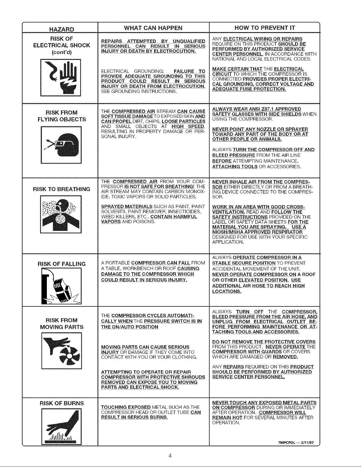
REPAIRS ATTEMPTED BY UNQUALIFIED
PERSONNEL CAN RESULT IN SERIOUS
INJURY OR DEATH BY ELECTROCUTION,
ELECTRICAL GROUNDING: FAILURE TO
PROVIDE ADEQUATE GROUNDING TO THIS
PRODUCT COULD RESULT IN SERIOUS
INJURY OR DEATH FROM ELECTROCUTION.
SEE GROUNDING INSTRUCTIONS.
ANY ELECTRICAL WIRING OR REPAIRS
REQUIRE ON THIS PRODUCT SHOULD BE
PERFORMED BY AUTHORIZED SERVICE
CENTER PERSONNEL. IN ACCORDANCE WITH
NATIONAL AND LOCAL ELECTRICAL CODES.
MAKE CERTAIN THAT THE ELECTRICAL
CIRCUIT TO WHICH THE COMPRESSOR IS
CONNECTED PROVIDES PROPER ELECTRI-
CAL GROUNDING, CORRECT VOLTAGE AND
ADEQUATE FUSE PROTECTION.
RiSK FROM
FLYING OBJECTS
RiSK TO BREATHING
N'q
RISK OF FALLING
THE COMPRESSED AiR STREAM CAN CAUSE
SOFT TISSUE DAMAGE TO EXPOSED SKIN AND
CAN PROPEL DIRT, CHIPS, LOOSE PARTICLES
AND SMALL OBJECTS AT HiGH SPEED,
RESULTING IN PROPERTY DAMAGE OR PER-
SONAL INJURY.
THE COMPRESSED AiR FROM YOUR COM-
PRESSOR IS NOT SAFE FOR BREATHING! THE
AIR STREAM MAY CONTAIN CARBON MONOX-
IDE, TOXIC VAPORS OR SOLID PARTICLES.
SPRAYED MATERIALS SUCH AS PAINT, PAINT
SOLVENTS, PAINT REMOVER, INSECTICIDES,
WEED KILLERS, ETC.. CONTAIN HARMFUL
VAPORS AND POISONS.
A PORTABLE COMPRESSOR CAN FALL FROM
A TABLE, WORKBENCH OR ROOF CAUSING
DAMAGE TO THE COMPRESSOR WHICH
COULD RESULT IN SERIOUS INJURY.
ALWAYS WEAR ANSi Z87,1 APPROVED
SAFETY GLASSES WITH SIDE SHIELDS WHEN
USING THE COMPRESSOR.
NEVER POINT ANY NOZZLE OR SPRAYER
TOWARD ANY PART OF THE BODY OR AT
OTHER PEOPLE OR ANIMALS,
ALWAYS TURN THE COMPRESSOR OFF AND
BLEED PRESSURE FROM THE AIR LINE
BEFORE ATTEMPTING MAINTENANCE,
ATTACHING TOOLS OR ACCESSORIES.
NEVER INHALE AIR FROM THE COMPRES-
SOR EITHER DIRECTLY OR FROM A BREATH-
ING DEVICE CONNECTED TO THE COMPRES-
SOR.
WORK IN AN AREA WITH GOOD CROSS-
VENTILATION. READ AND FOLLOW THE
SAFETY INSTRUCTIONS PROVIDED ON THE
LABEL OR SAFETY DATA SHEETS FOR THE
MATERIAL YOU ARE SPRAYING. USE A
NIOSH/MSHA APPROVED RESPIRATOR
DESIGNED FOR USE WITH YOUR SPECIFIC
APPLICATION.
ALWAYS OPERATE COMPRESSOR IN A
STABLE SECURE POSITION TO PREVENT
ACCIDENTAL MOVEMENT OF THE UNIT.
NEVER OPERATE COMPRESSOR ON A ROOF
OR OTHER ELEVATED POSITION, USE
ADDITIONAL AIR HOSE TO REACH HIGH
LOCATIONS.
RISK FROM
MOVING PARTS
RISK OF BURNS
THE COMPRESSOR CYCLES AUTOMATI-
CALLY WHEN THE PRESSURE SWITCH IS IN
THE ON/AUTO POSITION
MOVING PARTS CAN CAUSE SERIOUS
INJURY OR DAMAGE IF THEY COME INTO
CONTACT WITH YOU OR YOUR CLOTHING.
ATTEMPTING TO OPERATE OR REPAIR
COMPRESSOR WiTH PROTECTIVE SHROUDS
REMOVED CAN EXPOSE YOU TO MOVING
PARTS AND ELECTRICAL SHOCK.
TOUCHING EXPOSED METAL SUCH AS THE
COMPRESSOR HEAD OR OUTLET TUBE CAN
RESULT IN SERIOUS BURNS.
ALWAYS TURN OFF THE COMPRESSOR,
BLEED PRESSURE FROM THE AIR HOSE, AND
UNPLUG FROM ELECTRICAL OUTLET BE-
FORE PERFORMING MAINTENANCE OR AT-
TACHING TOOLS AND ACCESSORIES.
DO NOT REMOVE THE PROTECTIVE COVERS
FROM THIS PRODUCT. NEVER OPERATE THE
COMPRESSOR WITH GUARDS OR COVERS
WHICH ARE DAMAGED OR REMOVED.
ANY REPAIRS REQUIRED ON THIS PRODUCT
SHOULD BE PERFORMED BY AUTHORIZED
SERVICE CENTER PERSONNEL,
NEVER TOUCH ANY EXPOSED METAL PARTS
ON COMPRESSOR DURING OR IMMEDIATELY
AFTER OPERATION. COMPRESSOR WILL
REMAIN HOT FOR SEVERAL MINUTES AFTER
OPERATION.
TM P(::POL -- 3/11/97
Page 5
GLOSSARY
CFM: Cubic feet per minute.
SCFM: Standard cubic feet per minute; a unit of mea-
sure of air delivery.
PSIG: Pounds per square inch gauge; a unit of measure
of pressure.
ASME: American Society of Mechanical Engineers;
made, tested, inspected and registered to meet the
standards of the ASME.
U.L. Listed: This product is Listed by Underwriters
Laboratories, Inc. (UL). Samples of this product have
been evaluated by UL and meet applicable UL Stan-
dards for Safety.
Cut-In Pressure: While the motor is off, air tank
pressure drops as you continue to use your accessory.
When the tank pressure drops to a certain low level the
motor will restart automatically. The low pressure at
which the motor automatically re-starts is called "cut-in
pressure."
Cut-Out Pressure: When you turn on your air compres-
sor and itbegins to run, air pressure inthe air tank begins
to build. It builds to a certain high pressure before the
motor automatically shuts off - protecting your air tank
from pressure higher than its capacity. The high pres-
sure at which the motor shuts off is called "cut-out
pressure."
ACCESSORIES FOR USE WiTH SEARS
AIR COMPRESSORS
• SPRAY GUNS • QUICK CONNECTOR SETS • NAILER/STAPLERS
BLOW GUNS (various sizes) Decking
AIR CAULKING GUNS • VlSCOSlMETER Farming
PNEUMATIC POWER * AIR PRESSURE REGULATORS Roofing
WASHERS • OIL FOG LUBRICATORS Siding
SANDBLASTERS • AIR TOOLS: Finishing
AIR BRUSHES Sanders Carpentry
AIR LINE FILTERS Drills Upholstery
TIRE AIR CHUCKS Impact Wrenches Picture Framing
PAINT TANKS Hammers • DRAIN CLEANER
AIR TANKS • AIR HOSE: * DUSTER GUN
INFLATOR KITS 1/4", 5/16" or 3/8" I.D.in
various lengths
GENERAL iNFORMATiON
You have purchased an air compressor unit consisting
of a one cylinder, single-stage air compressor pump and
air tank. Included are wheels, regulator, gauges, and
handle.
This air compressor requires no oil. Now you can enjoy
all the benefits of having an air compressor without ever
having to purchase, add or change oil.
Your air compressor can be used for operating paint
spray guns, air tools, caulking guns, grease guns, air
brushes, sandblaster, or inflating tires and plastic toys,
spraying weed killers, insecticides, etc. An air pressure
regulator is supplied for the applications.
An air filter which removes moisture and dirt from com-
pressed air should be used where applicable.
These accessories can be purchased from most Sears
stores or from the Sears Power Tool Catalog.
Page 6
DESCRiPTiON OF OPERATION
Air Compressor Pump: To compress air, the piston
moves up and down inthe cylinder. Onthe downstroke,
air isdrawn inthrough the air intake valves. The exhaust
valves remain closed. On the upstroke of the piston, air
is compressed. The intake valves close and com-
pressed air is forced out through the exhaust valves,
through the outlet tube, through the check valve and into
the air tank. Working air is not available until the
compressor has raised the air tank pressure above that
required at the air outlet.
CheckValve: When the air compressor isoperating, the
check valve is"open", allowing compressed air to enter
the air tank. When the aircompressor reaches "cut-out"
pressure, the check valve "closes", allowing air pressure
to remain inside the air tank.
Pressure Release Valve: The pressure release valve
located on the side of the pressure switch, is designed
to automatically release compressed air from the com-
pressor head and the outlet tube when the air compres-
sor reaches "cut-out" pressure or is shut off. If the air is
not released, the motor will not be able to start. The
pressure release valve allows the motor to restart freely.
When the motor stops running, airwill be heard escaping
from the valve for a few seconds. No air should be
leaking when the motor is running.
Pressure Switch: The pressure switch automatically
starts the motor when the air tank pressure drops below
the factory set "cut-in" pressure. It stops the motor
when the air tank pressure reaches the factory set "cut-
out" pressure.
SafetyValve: Ifthe pressure switch does not shut offthe
air compressor at its cut-out pressure setting, the safety
valve will protect the tank against high pressure by
"popping out" at its factory set pressure (slightly higher
than the pressure switch cut-out setting).
Regulator: The air pressure coming from the air tank is
controlled by the regulator. Turn the regulator knob
clockwise to increase pressure and counter-clockwise
to decrease pressure. To avoid minor readjustment
after making a change in pressure setting, always ap-
proach the desired pressure from a lower pressure.
When reducing from a higher to a lower setting, first
reduce to some pressure less than that desired, then
bring up to the desired pressure. Depending on the air
requirements of each particular accessory, the outlet
regulated air pressure may have to be adjusted while
operating the accessory.
Outlet Pressure Gauge: The outlet pressure gauge
indicates the air pressure available at the outlet side of
the regulator. This pressure is controlled by the regula-
tor and is always less or equal to the tank pressure. See
"Operating Procedures".
Tank Pressure Gauge: The tank pressure gauge indi-
cates the reserve air pressure in the tank.
Cooling System: This compressor contains an ad-
vanced design cooling system. At the heart of this
cooling system is an engineered fan. It is perfectly
normal for this fan to blow air through the vent holes in
large amounts. You know that the cooling system is
working when air is being expelled.
ASSEMBLY
Tools Needed for Assembly
• a9/16" socket or open end wrench for attaching the
wheels
a 3/8" open end wrench or socket to tighten handle
screws
installing Wheels, Handle, Rubber
Foot Strip
THE WHEELS AND HANDLE DO NOT PRO=
ViDE ADEQUATE CLEARANCE, STABILITY
OR SUPPORT FOR PULLING THE UNIT UP
AND DOWN STAIRS OR STEPS. THE UNIT
MUST BE LIFTED, OR PUSHED UP A RAMP.
1.
Attach the handle to the compressor saddle by
inserting the handle inside the compressor saddle
and lining upthetwo bolt holes on each side. Install
the four screws, two on each side. Tighten securely.
It will be necessary to brace or support one
side of the outfit when installing the wheels
because the compressor will have a ten=
dency to tip.
2.
Install one shoulder bolt and one nut for each wheel.
Tighten securely. The outfit will sit level if the wheels
are properly installed.
3.
Clean and dry underside of air tank leg opposite
wheels. Remove the protective paper strip from the
adhesive backed rubber foot strip. Attach the rub-
ber foot strip to the bottom of leg. Press firmly into
place.
Page 7
iNSTALLATiON AND BREAK-iN PROCEDURES
Location of the Air Compressor
Locate the air compressor in a clean, dry and well
ventilated area. The air filter must be kept clear of
obstructions which could reduce air delivery of the air
compressor. The air compressor should be located at
least 12" away from a wall or other obstructions that will
interfere with the flow of air. The air compressor head
and shroud are designed to allow for proper cooling.
Lubrication and Oil
This unit needs no lubrication or oiling.
Extension Cords
Use extra air hose instead of an extension cord to avoid
voltage drop and power loss to the motor, and to prevent
overheating.
If an extension cord must be used, be sure it is:
• a 3-wire extension cord that has a 3-blade ground-
ing plug, and a 3-slot receptacle that will accept the
plug on the product
• in good condition
• no longer than 50 feet
• 12 gauge (AWG) or larger. (Wire size increases as
gauge number decreases. 10AWG and 8AWG may
also be used. DO NOT USE 14 OR 16 AWG.)
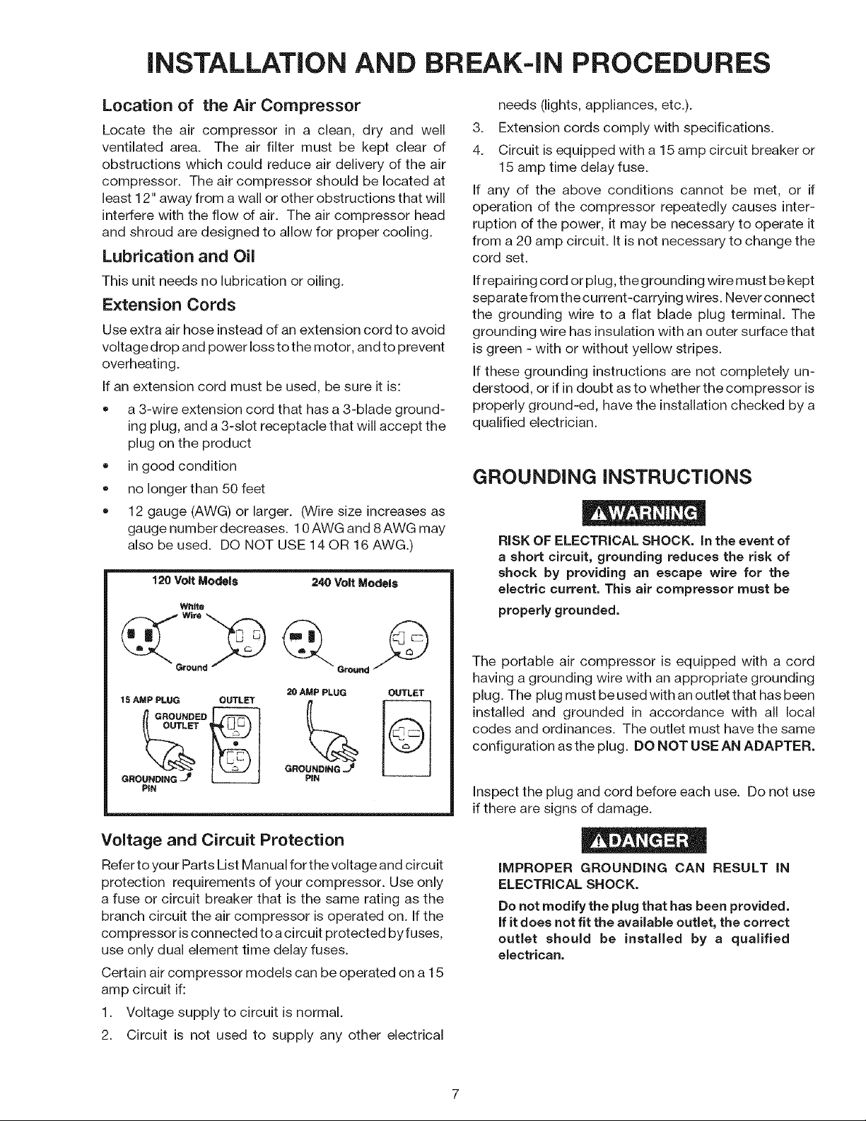
120 Volt Models 240 Volt Models
White
needs (lights, appliances, etc.).
3. Extension cords comply with specifications.
4. Circuit is equipped with a 15 amp circuit breaker or
15 amp time delay fuse.
If any of the above conditions cannot be met, or if
operation of the compressor repeatedly causes inter-
ruption of the power, it may be necessary to operate it
from a 20 amp circuit. It is not necessary to change the
cord set.
If repairing cord or plug, the grounding wire must be kept
separate from the current-carrying wires. Never connect
the grounding wire to a flat blade plug terminal. The
grounding wire has insulation with an outer surface that
isgreen - with or without yellow stripes.
If these grounding instructions are not completely un-
derstood, or ifin doubt as to whether the compressor is
properly ground-ed, have the installation checked by a
qualified electrician.
GROUNDING INSTRUCTIONS
RiSK OF ELECTRICAL SHOCK. in the event of
a short circuit, grounding reduces the risk of
shock by providing an escape wire for the
electric current. This air compressor must be
properly grounded.
15 AMP PLUG OUTLET
GROUNDING -_
PIN
20 AMP PLUG
GROUNDING J_
PIN
OUTLET
Voltage and Circuit Protection
Refer to your Parts List Manual for the voltage and circuit
protection requirements of your compressor. Use only
a fuse or circuit breaker that is the same rating as the
branch circuit the air compressor is operated on. If the
compressor isconnected to a circuit protected by fuses,
use only dual element time delay fuses.
Certain air compressor models can be operated on a 15
amp circuit if:
1. Voltage supply to circuit is normal.
2. Circuit is not used to supply any other electrical
The portable air compressor is equipped with a cord
having a grounding wire with an appropriate grounding
plug. The plug must be used with an outlet that has been
installed and grounded in accordance with all local
codes and ordinances. The outlet must have the same
configuration as the plug. DO NOT USE AN ADAPTER.
Inspect the plug and cord before each use. Do not use
ifthere are signs of damage.
IMPROPER GROUNDING CAN RESULT IN
ELECTRICAL SHOCK.
Do not modify the plug that has been provided.
if it does not fit the available outlet, the correct
outlet should be installed by a qualified
electrican.
Page 8
Break-in Procedure
Serious damage may result if the following
break-in instructions are not closely fol-
lowed.
This procedure is required only once, before the air
compressor is put into service.
1. Set the pressure switch OFF/AUTO lever to the
"OFF" position.
OPERATING PROCEDURES
2. Plug the power cord into the correct branch circuit
receptacle.
3. Turn the regulator clockwise, opening itfully to
prevent air pressure build-up in the tank.
4. Move the OFF/AUTO lever to "AUTO". The com-
pressor will start.
5. Run the compressor for 15 minutes. Make sure the
regulator is open and there isno tank pressure build-
up.
6. After 15 minutes, close the regulator by turning it
counterclockwise. The air tank will fill to cut-out
pressure and the motor will stop.
1. Before attaching air hose or accessories, make sure
the OFF/AUTO lever is set to "OFF" and the air
regulator is closed.
2. Attach hose and accessories.
TOO MUCH AiR PRESSURE CREATES A HAZ-
ARDOUS RiSK OF BURSTING. CAREFULLY FOL-
LOW STEPS 3 AND 5 EACH TiME THE COMPRES-
SOR IS USED.
Compressed air from the unit may contain water
condensation. Do not spray unfiltered air at an
item that could be damaged. Some air operated
tools or devices may require filtered air. Read the
instructions for the air tool or device.
3_
Check the manufacturer's maximum pressure rat-
ing for air tools and accessories. The regulator
outlet pressure must never exceed the maximum
pressure rating. If your compressor is not supplied
with a regulator with gauge, install one before using
accessories.
4_
Turn the OFF/AUTO lever to AUTO and allow tank
pressure to build. Motor will stop when tank pres-
sure reaches "cut-out" pressure.
5. Open the regulator by turning it clockwise. Adjust
the regulator to the correct pressure setting. Your
compressor is ready for use.
6. Always operate the air compressor in well-venti-
lated areas; free of gasoline or other solvent vapors.
7. Do not operate the compressor near the spray area.
When you are finished:
8. Set the OFF/AUTO lever to "OFF".
9. Turn the regulator counterclockwise and set the
outlet pressure to zero.
10. Remove the air tool or accessory.
11. Open the regulator and allow the air to slowly bleed
from the tank. Close the regulator when tank pres-
sure is approximately 20 psi.
12. Drain water from air tank.
WATER WiLL CONDENSE iN THE AiR TANK. iF
NOT DRAINED, WATER WiLL CORRODE AND
WEAKENTHEAIRTANKCAUSINGA RISK OFAiR
TANK RUPTURE.
With tank pressure at approximately 20 psi, open the
drain cock or drain valve.
13. After the water has been drained, close drain
cock or drain valve. The air compressor can now
be stored.
Page 9
MAINTENANCE
UNiT CYCLES AUTOMATICALLY WHEN POWER iS ON. WHEN DOING MAINTENANCE, YOU MAY BE EXPOSED TO
VOLTAGE SOURCES, COMPRESSED AiR OR MOVING PARTS. PERSONAL iNJURiES CAN OCCUR. BEFORE PERFORM=
ING ANY MAINTENANCE OR REPAIR, UNPLUG THE COMPRESSOR AND BLEED OFF ALL AiR PRESSURE.
ALL MAINTENANCE AND REPAIR OPERATIONS NOT LISTED MUST BE DONE BY
OUAMFIED SERVICE PERSONNEL.
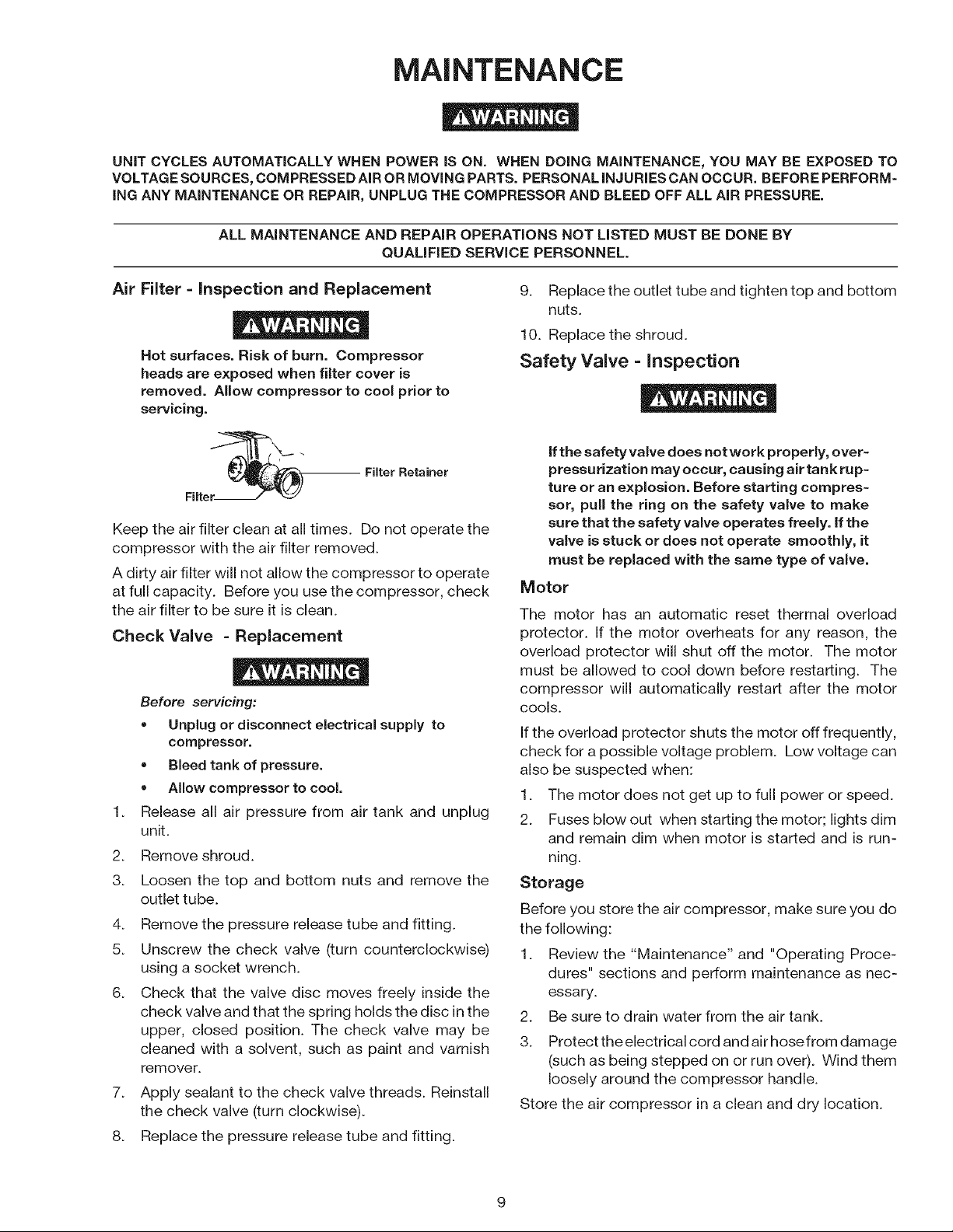
Air Filter =inspection and Replacement
Hot surfaces. Risk of burn. Compressor
heads are exposed when filter cover is
removed. Allow compressor to cool prior to
servicing.
Filter Retainer
Filter.
Keep the air filter clean at all times. Do not operate the
compressor with the air filter removed.
A dirty air filter will not allow the compressor to operate
at full capacity. Before you use the compressor, check
the air filter to be sure it is clean.
Check Valve = Replacement
Before servicing:
• Unplug or disconnect electrical supply to
compressor.
• Bleed tank of pressure.
• Allow compressor to cool.
Release all air pressure from air tank and unplug
unit.
2.
Remove shroud.
3.
Loosen the top and bottom nuts and remove the
outlet tube.
4.
Remove the pressure release tube and fitting.
5.
Unscrew the check valve (turn counterclockwise)
using a socket wrench.
6.
Check that the valve disc moves freely inside the
check valve and that the spring holds the disc in the
upper, closed position. The check valve may be
cleaned with a solvent, such as paint and varnish
remover.
7_
Apply sealant to the check valve threads. Reinstall
the check valve (turn clockwise).
8.
Replace the pressure release tube and fitting.
9. Replace the outlet tube and tighten top and bottom
nuts.
10. Replace the shroud.
Safety Valve = inspection
ifthe safety valve does not work properly, over-
pressurization may occur, causing air tank rup-
ture or an e×plosion. Before starting compres-
sor, pull the ring on the safety valve to make
sure that the safety valve operates freely, ifthe
valve is stuck or does not operate smoothly, it
must be replaced with the same type of valve.
Motor
The motor has an automatic reset thermal overload
protector. If the motor overheats for any reason, the
overload protector will shut off the motor. The motor
must be allowed to cool down before restarting. The
compressor will automatically restart after the motor
cools.
If the overload protector shuts the motor off frequently,
check for a possible voltage problem. Low voltage can
also be suspected when:
1. The motor does not get up to full power or speed.
2. Fuses blow out when starting the motor; lights dim
and remain dim when motor is started and is run-
ning.
Storage
Before you store the air compressor, make sure you do
the following:
1. Review the "Maintenance" and "Operating Proce-
dures" sections and perform maintenance as nec-
essary.
2. Be sure to drain water from the air tank.
3. Protect theelectrical cord and air hosefrom damage
(such as being stepped on or run over). Wind them
loosely around the compressor handle.
Store the air compressor in a clean and dry location.
Page 10

TROUBLESHOOTING GUIDE
PERFORMING REPAIRS MAY EXPOSE VOLTAGE SOURCES, MOVING PARTS OR COM=
PRESSED AiR SOURCES. PERSONAL iNJURY MAY OCCUR. PRIOR TO ATTEMPTING ANY
REPAIRS, UNPLUG THE COMPRESSOR AND BLEED OFF TANK AiR PRESSURE.
PROBLEM
Excessive tank pressure -safety
valve pops off.
Air leaks at fittings.
Air leaks at pressure switch re-
lease valve.
CAUSE
Pressure switch does not shut off mo-
tor when compressor reaches "cut-
out" pressure.
Pressure switch "cut-out" too high.
Tube fittings are not tight enough.
Defective pressure switch release
valve.
Defective flapper valve in manifold.
Check valve seat damaged.
CORRECTION
Move the pressure switch lever to the "OFF" position.
Ifthe unit doesn't shut off, and the electrical contacts
are welded together, replace the pressure switch.
Return the outfit to Sears Service Center to check
and adjust, or replace switch.
Tighten fittings where air can be heard escaping.
Check fittings with soapy water solution. DO NOT
OVERTIGHTEN.
Remove and replace the release valve.
Check to see if the pin inthe bottom of the pressure
release valve is stuck. If it does not move freely,
replace the valve.
A defective flapper valve results in aconstant air leak
at the pressure release valve when there is pressure
in the tank and the compressor is shut off. Remove
and clean or replace valve.
Inspect and replace upper manifold assembly.
Air leaks inair tank or at air tank
welds.
Air leaks between head and Leaking seal. Torque head screws to 8 ft. Ibs. If this does not stop
valve plate, leak, replace seal.
Pressure reading on the It is normal for "some" pressure drop
regulated pressure gauge to occur.
drops when an accessory is
used.
Defective air tank.
Air tank must be replaced. Do not repair the leak.
DO NOT DRILL iNTO, WELD OR OTHER=
WiSE MODIFY AiR TANK OR iT WiLL
WEAKEN. THE TANK CAN RUPTURE OR
EXPLODE.
Ifthere isan excessive amount of pressure drop when
the accessory is used, adjust the regulator following
the instructions on page 6.
NOTE
Adjust the regulated pressure under flow condi-
tions (while accesory is being used).
10
Page 11

TROUBLESHOOTING GUIDE (Continued)
PROBLEM CORRECTION
Air leak from safety valve. Operate safety valve manually by pulling on ring. If
Knocking Noise Remove and clean, or replace.
Compressor is not supplying
enough air to operate
accessories.
Motor will not run or restart.
CAUSE
Possible defect in safety valve.
Defective check valve.
Prolonged excessive use of air.
Compressor is not large enough for air
requirement.
Restricted air intake filter.
Hole in hose.
Check valve restricted.
Air leaks.
Motor overload protection switch has
tripped.
Tank pressure exceeds pressure switch
"cut-in" pressure.
valve still leaks, it should be replaced.
Decrease amount of air usage.
Check the accessory air requirement. If it is higher
than the SCFM or pressure supplied by your air
compressor, you need a larger compressor.
Clean or replace air intake filter. Do not operate the
air compressor in the paint spray area.
Check and replace if required.
Remove and clean, or replace.
Tighten fittings. (See Air Leaks Section of Trou-
bleshooting Guide.)
Let motor cool off and overload switch will automati-
cally reset.
Motor will start automatically when tank pressure
drops below "cut-in" pressure of pressure switch.
Wrong gauge wire or length of exten-
sion cord.
Check valve stuck open.
Loose electrical connections.
Possible defective motor or capacitor.
Paint spray on internal motor parts.
Fuse blown, circuit breaker tripped.
Pressure release valve on pressure
switch has not unloaded head pres-
sure.
Check for proper gauge wire and cord length.
Remove and clean, or replace.
Check wiring connection inside pressure switch and
terminal box area.
Return to Sears Service Center for inspection or
replacement, if necessary.
Have checked at Sears Service Center. Do not
operate the compressor in the paint spray area. See
flammable vapor warning.
1. Check fuse box for blown fuse and replace, if
necessary. Reset circuit breaker. Do not use a
fuse or circuit breaker with higher rating than
that specified for your particular branch circuit.
2. Check for proper fuse. Only time delay fuses are
acceptable.
3. Check for low voltage conditions and/or proper
extension cord.
4. Disconnect the other electrical appliances from
circuit or operate the compressor in its own
branch circuit.
Bleed the line by pushing the lever on the pressure
switch to the "off" position; if the valve does not
open, replace it.
Broken exhaust valve. Inspect and replace if necessary.
Regulator knob continuous air Dirty or damaged regulator internal Clean or replace regulator, or internal parts.
leak. Regulator will not shut off parts.
at air outlet.
11
Page 12

SERVICE NOTES
12
Page 13

SERVICE NOTES
13
Page 14

PERMANENTLY LUBRICATED
TANK MOUNTED
MANUAL
When requesting service or ordering
parts, always provide the following
information:
= Model Number
• Part Number
• Part Description
• Name of Item
AIR COMPRESSOR
For the repair or replacement parts you need
Call 7 am - 7 pro, 7 days a week
1 =800=366=PART
(1-800-366-7278)
For in-home major brand repair service
Call 24 hours a day, 7 days a week
1 =8OO=4=REPAIR
(1-800-473-7247)
FULL ONE YEAR
WARRANTY
AIR COMPRESSOR
If this air compressor fails due to a defect in
material or workmanship within one year
from the date of purchase, RETURN IT TO
THE NEAREST SEARS REPAIR CENTER
THROUGHOUT THE UNITED STATES
AND SEARS WILL REPAIR IT, FREE OF
CHARGE. IF PURCHASED FROM OR-
CHARD SUPPLY HARDWARE, RETURN
TO THE NEAREST ORCHARD STORE
AND ORCHARD WILL REPAIR IT, FREE
OF CHARGE.
Ifthis air compressor is used for commercial
or rental purposes, the warranty will apply
for ninety days from the date of purchase.
This warranty gives you specific legal rights
and you may have other rights which vary
from state to state.
For the location of a
Sears Parts and Repair Center in your area
Call 24 hours a day, 7 days a week
1 =800=488= 1222
For information on purchasing a Sears
Maintenance Agreement or to inquire
about an existing Agreement
call 9 am - 5 pro, Monday-Saturday
1 =800=827=6655
America's Repair Specialists
Sears, Roebuck and Co., Hoffman Estates, |L 60179 U.S.A.
Page 15

MAN IAL
DEL
PERADOR
®
COMPRESOR DE AIRE
DE LUBRICACIC)N
PERMANENTE
MONTADO EN EL TANQUE
• PAUTAS DE SEGURiDAD
ENSAMBLAJE
OPERAC|ON
IVlANTENiMiENTO
DIAGNOST|CO DE PROBLEMAS
IMPORTANTE:
Leer las pautas de seguridad y
todas ias Instrucciones Cuidado-
sarnente antes de operar.
Sears, Roebuck and Co., Hoffman Estates, |L 60179 U.S.A.
MG2-OILFREE Rev. 7/26199
Page 16

TABLA DE CONTENIDOS
P_gina
PAUTAS DE SEGURIDAD ................................................................................................. 3
TABLA DE ADVERTENCIAS ............................................................................................. 3
GLOSARIO ........................................................................................................................ 5
ACCESORIOS PARA USAR CON COMPRESORES DE AIRE DE SEARS ....................... 5
INFORMACION GENERAL ............................................................................................... 5
DESCRIPCION DE LA OPERACION ................................................................................. 6
ENSAMBLAJE ................................................................................................................... 7
INSTALACiON Y ASENTAMiENTO ................................................................................... 7
Ubicaci6n del Compresor de Aire ............................................................................... 7
Aceite y Lubricaci6n .................................................................................................... 7
Cordones de Extensi6n ............................................................................................... 7
Voltaje y Proteccion Contra la Corriente ..................................................................... 7
Instrucciones para Conexi6n a Tierra ......................................................................... 8
Procedimientos Para el Asentamiento ........................................................................ 8
PROCEDIMIENTOS PARA OPERAR ................................................................................ 9
MANTENIMIENTO ........................................................................................................... 10
Filtro de Aire - Inspecci6n y Reemplazo ................................................................... 10
VAIvula de Chequeo - Reemplazo ............................................................................. 10
VAIvula de Seguridad - Inspecci6n ........................................................................... 10
Motor ......................................................................................................................... 1 0
Almacenamiento ....................................................................................................... 10
GUiA DE DIAGNOSTICO DE PROBLEMAS ................................................................... 11
COMO ORDENAR REPUESTOS .................................................................................... 14
GARANT_ ...................................................................................................................... 14
2-SP
Page 17

INSTRUCCiONES IMPORTANTES DE SEGURiDAD
J
LA OPERACION INAPROPIADA DE ESTA UNIDAD PUEDE CAUSAR LESIONES SERIAS Y
DAI_IOS A LA PROPiEDAD. LEER Y ENTENDER TODAS LAS ADVERTENCiAS DE SEGURiDAD
E INSTRUCCiONES DE OPERACiON ANTES DE USAR ESTA UNiDAD.
RIESGO
RIESGO DE
EXPLOS|ON
TANQUE DE AIRE
LAS SIGUIENTES CONDICIONES PODRJAN
CONDUCIR AL DEBILITAMIENTO DEL TANQUE
DANDO COMO RESULTADO UNA VIOLENTA
EXPLOSION DEL TANQUE:
1. OMITIR DRENAR APROPIADAMENTE EL
2. MODIFICACIONESO INTENTOS DE REPARAR
3. MO DIFICACION ES NO AUTORIZADAS AL CON-
QUE PUEDE SUCEDER COMO EVITARLO
AGUA CONDENSADA QUE OXIDARA EL
TANQUE DE ACERO, DEBILITANDOLO Y
ADELGAZANDO SUS PAREDES.
EL TANQUE.
TROL DE PRESION,V_,LVULA DE SEGURIDAD
O A CUALQUIER OTRO COMPONENTE QUE
CONTROLE LA PRESION DEL TANQUE.
DRENAR EL TANQUE DIARIAMENTE O DESPUES
DE CADA USO. SI SE LE PRODUCE UNA FUGAAL
TANQUE, REEMPLAZARLO INMEDIATAMENTE POR
OTROTANQUE NUEVO O UN COMPRESOR NUEVO.
NUNOA TALADRAR, SOLDAR NI HAOER
MODIFIOAOI6N ALGUNA AL TANQUE NI A SUS
ADITAMENTOS.
EL TANQUE ESTA DISENADO PARA RESISTIR LAS
PRESIONES DE TRABAJO ESPECIFICADAS. NUNOA
SUBSTITUIR PARTES NI ALTERAR LAS
REGULACIONES NI PRESIONES DE TRABAJO
PRERJADOS EN FABRIOA.
ADITAMENTOS Y ACCESORIOS
EXCEDER LA CAPACIDAD DE PRESION DE LAS
HERRAMIENTAS NEUMATICAS PISTOLAS
ROCIADORAS, ACCESORIOS PARA AIRE,
NEUMATICOS / LLANTAS, Y OTROS ARTiCULOS
INFLABLES PUEDEN HACERLOS EXPLOTAR O
SALIR DISPARADOS CAUSANDO LESION ESSERIAS.
LAS VIBRACIONES EXCESIVAS PUEDEN
DEBILITAR EL TANQUE ESTACIONARIO Y
CAUSAR UNA EXPLOSION.
SIEMPRE OBSERVAR LAS RECOMENDACIONES DEL
FABRICANTE DEL EQUIPO Y NUNCA EXCEDER LA
PRESION MAXIMA ESPECIFICADA PARA UN
ADITAMENTO. NUNOA USAR EL COMPRESOR
PARA INFLAR OBJETOS PEQUE_IOS DE BAJA
PRESK)N TALES COMO JUGUETES DE Nl_lOS,
PELOTAS DE FUTBOL BALONCESTO, ETC.
EL COMPRESOR DEBE ESTAR DEBIDAMENTE
MONTADO, VER LOS PROCEDIMIENTOS DE
INSTALACION.
R|ESGO DE |NCENDiO 0
EXPLOS|ON
RIESGO DE CHOQUE
)
ES NORMAL QUE LOS CONTACTOS ELECTRICOS
EN EL MOTOR Y EL INTERRUPTOR DE PRESION
EMITAN CHISPAS.
Sl LAS CHISPAS DEL COMPRESOR ENTRAN EN
CONTACTO CON VAPORES INFLAMABLES,
ESTOS PUEDEN ENOENDERSE CAUSANDO UN
INCENDIO O UNA EXPLOSION.
LA OBSTRUCCION DE CUALQUIERA DE LAS
ABERTURAS DE VENTILACION DEL
COMPRESOR PUEDE CAUSAR UN SERIO
SOBRECALENTAMIENTO Y UN INCENDIO.
EL COMPRESOR DE AIRE OPERA CON
ELECTRICIDAD. COMO CUALQUIER OTRO
DISPOSITIVO ELECTRICO, PUEDE CAUSAR
CHOQUE ELECTRICO Sl NO SE USA
ADECUADAMENTE.
3- SP
SIEMPRE OPERAR EL COMPRESOR DE AIRE EN
AREAS BIEN VENTILADAS, SiN MATERIALES
COMBUSTIBLES NI VAPORES DE GASOMNA NI
DE OTROS SOLVENTES.
SI SE ROCiAN MATERIALES INFLAMABLES,
COLOCAR EL COMPRESOR POR LO MENOS A 6
M (20') DEL AREA DE PULVERIZACION. PUEDE
SER NECESARIO USAR UNA MANGUERA MAS
LARGA.
GUARDAR LAS SUBSTANClAS INFLAMABLES EN
UN LUGAR SEGURO LEJOS DEL COMPRESOR.
NUNCACOLOCAR OBJ ETOS CONTRA NI ENCIMA
DELCOMPRESOR. OPERAR ELCOMPRESOR EN
UN AREA ABIERTA A POR LO MENOS 30
CENTiMETROS DE CUALQUIER PARED U
OBSTRUCCl6N QUE PUEDA RESTRINGIR EL
FLUJO DE AIRE FRESCO POR LAS ABERTURAS DE
VENTILACION
NUNCA OPERAR EL COMPRESOR EN EL EXTE-
RIOR CUANDO ESTE LLOVIENDO.
NUNCA OPERAR EL COMPRESOR SiN LAS
CUBIERTAS DE LOS COMPONENTES O CON LAS
CUBIERTAS DA_IADAS.
CONTINUA EN LA SIGUIENTE P,4GINA
Page 18

RIESGO
QUE PUEDE SUCEDER COIVIO EVITARLO
RIESGO DE CHOQUE
ELECTRICO (Cont,)
)
RIESGO DiE OBJETOS
PROPULSADOS
R|ESGO A LA
RESP|RAC|ON
LASREPARACIONES EFECTUADAS POR PERSONAL
NO CALIFICADO PUEDEN RESULTAR EN
LESIONES SERIAS O MUERTE DEBIDO A
ELECTROCUCION,
CONEXION A TIERRA: EL NO RACER
ADECUADAMENTE LA CONEXION A TIERRA DE LA
UNIDAD PUEDE CAUSAR LESIONES SERIAS O
MUERTE DEBIDO A ELECTROCUCION, VER LAS
INSTRUCCIONES DE CONEXION A TIERRA
APLICABLES.
EL CHORRO DE AIRE COMPRIMIDO PUEDE DAI_AR
EL TEJIDO HUMANO BLANDO Y PUEDE
IMPULSAR TIERRA, PARTJCULAS SUELTAS Y
OBJETOS PEQUENOS AVELOCIDADES ALTAS,
CAUSANDO DAI_OS MATERIALES O LESIONES
PERSONALES.
ELAIRE COMPRIMIDO PRODUCIDO POR LA UNIDAD
iNO ES SEGURO PARA RESPIRAR! EL CHORRO DE
AIRE PUEDE CONTENER MONOXIDO DE CARBONO,
OTROS VAPORES TOXICOS U OTRAS PART[CULAS.
LAS SUBSTANCIAS PULVERIZADAS TALES COMO
PINTURAS, SOLVENTES DEPINTURA, REMOVEDORES
DE PINTURA, INSECTICIDAS, HERBICIDAS, ETC.,
CONTIENEN VAPORES DANINOS Y VENENOSOS.
TODO CABLEADO O REPARACION QUE ESTA
UNIDAD REQUIERA DEBE REALIZARLA UN
PERSONAL OALIFICADO DE SERVlCIO ACATANDO
LOS CODIGOS ELECTRICOS NACIONALES Y LO-
CALES.
ASEGURARSE QUE EL CIRCUITO ELECTRICO AL
CUAL EST/k CONECTADO EL COMPRESOR, ESTI_
CONECTADO A TIERRA EN FORMA APROPIADA,
PROVEA EL V©LTAJE CORRECTO Y TENGA
PROTECCION ADECUADA MEDIANTE FUSIBLES.
AL USAR EL COMPRESOR SIEMPRE USAR GAFAS
DE SEGURIDAD CON PROTECTORES LATERALES
QUE CUMPLAN CON LA NORMA ANSI Z87.1.
NUNCA APUNTAR LA BOQUILLA O EL ROClADOR
HACIA PARTES DELCUERPO, OTRAS PERSONAS NI
AANIMALES.
SIEMPRE APAGAR EL COMPRESOR Y ALIVIAR LA
PRESION DE LAL[NEA DEAIRE ANTES DEINTENTAR
DARLE MANTENIMIENTO O CONEOTAR
HERRAMIENTAS O ACCESORIOS.
NUNCA INHALAR EL AIRE PROVENIENTE DEL
COMPRESOR, YA SEA DIRECTAMENTE O A TRAVES
DE UN DISPOSITIVO PARA RESPIRAR CONECTADO
AL COMPRESOR.
TRABAJAR EN UN AREA BIEN VENTILADA. LEER Y
SEGUIR LAS INSTRUCCIONES DE SEGURIDAD
PROVISTAS EN LAS ETIQUETAS Y HOJAS DE DATOS
DE SEGURIDAD DEL MATERIAL QUE SE ESTA
PULVERIZANDO. USAR UN RESPIRADOR
APROBADO POR NIOSH/MSRA Y DISEI_ADO PARA
LA APLIOACION ESPECiFICA.
R|ESGO DE CAJDAS
R|ESGO DE PIEZAS
MOVIBLES
R|ESGO
UNCOMPRESORPORTATILPUEDECAERSEDEUNA
MESA, BANCO DE TRABAJO O TECHO, CAUSANDO
DANOS AL COMPRESOR QUE LUEGO PUEDEN
CAUSARLESIONESSERIAS.
iEI COMPRESOR DE AIRE ENTRA EN
FUNCIONAMIENTO AUTOMATICAMENTE CUANDO
EL INTERRUPTOR DE PRESION ESTA EN LA
POSICION DEON/AUTO (PRENDIDO/AUTOMATICO}!
LAS PIEZAS MOVIBLES PUEDEN CAUSAR SERIAS
LESIONES PERSONALES SI ENTRAN EN CONTACTO
CON EL OPERADOR O SU ROPA.
INTENTAR OPERAR O DARLE MANTENIMIENTO AL
COMPRESOR SiN LAS CUBIERTAS PROTECTORAS
PUEDE EXPONER AL OPERADOR A PIEZAS
MOVIBLES Y A RIESGO DE ELECTROCUCION,
ELCONTACTOCON PiEZASCALIENTESTALESCOMO
EL CABEZAL DEL COMPRESOR O LOS TUBOS DE
SIEMPRE OPERAR LOS COMPRESORES EN UNA
POSICION SEGURA Y ESTABLE PARA EVITAR QUE
LA UNIDAD SE MUEVAACCIDENTALMENTE. NUNCA
OPERAR LA UNIDAD EN UN TECRO NI SUPERFICIE
ELEVADA ALGUNA, USAR UNA MANGUERA
NEUM/kTICA MAS LARGA PARA ALCANZAR LOS
LUGARES ELEVADOS.
SIEMPRE APAGAR EL COMPRESOR, ALIVIAR LA
PRESION DE LA MANGUERA NEUMATICA Y
DESCONECTAR LA UNIDAD DE CUALQUIER
ACCESORIO ANTES DE HAOER MANTENIMIENTO O
CONECTAR HERRAMIENTAS O ACCESORIOS.
NO QUITARLE. LAS CUBIERTAS PROTECTORAS A
ESTA U NIDAD. NUNCA OPERAR EL COMPRESOR SiN
LAS CUBIERTAS DE LOS COMPONENTES O CON
LAS CUBIERTAS DANADAS.
CUALQUIER REPARACION REQUERIDA POR ESTA
UNIDAD DEBERA HACERLA EL PERSONAL DEL
CENTRO DE SERVIOIO AUTORIZADO.
N UN CA TOCAR LOS COMPONENTES EXPUESTOS
DEL COMPRESOR DURANTE O INMEDIATAMENTE
DESPUES DE LA OPERACION. EL OOMPRESOR SE
MANTENDRA CALIENTE POR VARIOS MINUTOS
DESPUES DE LA OPERACION.
4-SP
Page 19

GLOSSARY
CFM: Pies cQbicos por minuto
SCFM: Pies cQbicos estandar por minuto; una unidad
de medida del aire producido.
PSIG: Libras por pulgada cuadrada leidas en el
man6metro, una unidad de medida de presi6n.
ASME: American Society of Mechanical Engineers
(Sociedad Americana de Ingenieros Meca.nicos);
hecho, probado, inspeccionado y registrado para
cumplir con los estandares de ASME.
Registrado por UL: Este producto esta registrado
por Underwriters Laboratories, Inc. (UL). Muestras de
este producto hart sido evaluadas por UL y cumplen
con los Estb,ndares aplicables de seguridad de UL.
ACCESORIOS PARA USAR CON LOS
COMPRESORES DE AIRE DE SEARS
• PISTOLAS
PULVERIZADORAS
• DESEMPOLVADORES
• PISTOLAS APLICADORAS
DE MASILLA
PARA LAVADORAS A
PRESION PISTOLAS
• SOPLETES DE ARENA
• BROCHAS DEAIRE
• FILTROS DEAIRE
• MANDRILES NEUMATICOS
PARA RUEDAS
• TANQUES DE PINTURA
• TANQUES DEAIRE
• EQUIPOS INFLADORES
• JUEGOS DECONEXION
RAPIDA (varios tama_os)
• MEDIDORES DE VISCOSIDAD
• REGULADORES DE PRESION
DE AIRE
• LUBRICADORES
PULVERIZADORES
• HERRAMIENTAS
NEUMATICAS
Lijadoras
Taladros
Llaves de Impacto
Martillos
• MANGUERA NEUMATICA
1/4", 5/16" o 3/8" Diam. Int.
De varias longitudes
PRESION DE ARRANQUE: Cuando el motor esta
apagado, la presi6n de aire va disminuyendo confor-
me usted continQa usando el accesorio. Cuando la
presiSn del tanque cae a cierto bajo nivel, el motor
arranca automaticamente. Esa baja presi6n a la cual
el motor arranca automaticamente, se llama "presiSn
de arranque"
PRESION DE CORTE: Cuando usted arranca el com-
presor de aire y empieza a funcionar, el aire dentro
del tanque comienza a acumularse hasta cierto nivel
de presiSn a la cual el motor se apaga
automa.ticamente para proteger su tanque de aire de
presiones que exceden su capacidad. La presiSn a
lacual el motor se apaga se llama "presi6n de corte".
• CLAVADORES/
ENGRAPADORAS
Para usar en:
Terrazas/Plataformas
Agricultura
Techos
Forros de paredes
Exteriores
Acabados
Carpinteria
Tapiceria
Enmarcados
• LIMPIEZA DE DRENAJES
• PISTOLAS
DESEMPOLVADORAS
INFORMACION GENERAL
Usted ha comprado una unidad compresora de aire
consistente en una bomba compresora de aire
monoetapica de un solo cilindro, un tanque de aire,
ruedas, asa e instrumentos y controles relacionados.
Este compresor de aire no requiere aceite. Ahora
usted puede gozar de todos los beneficios que le
brinda tener un compresor de aire sin tener que
comprar, agregar o cambiar aceite.
Su compresor de aire puede usarse para operar
pistolas pulverizadoras de pintura, herramientas
neuma.ticas, pistolas aplicadoras de masilla, pistolas
aplicadoras de grasa, sopletes de aire para limpiar,
sopletes de arena, inflar Ilantas o neum&ticos y
juguetes de plastico, rociar herbicidas, insecticidas,
etc. Se requiere un regulador de aire para la mayoria
de las aplicaciones.
Cuando fuese necesario, se debe usar un
transformador de aire independiente que combine las
funciones de regulaci6n de aire y/o eliminaci6n de
humedad y suciedad.
Estos accesorios pueden comprarse en la mayoria
de Tiendas Sears o por medio del Catalogo de
Herramientas Electricas/Neuma.ticas de Sears.
5- SP
Page 20

DESCRIPCION DE
LA OPERACION
Bomba de A[re Comprimido: Para comprimir aire,
el pist6n se mueve de arriba a abajo en el cilindro. En
la carrera hacia abajo, el aire ingresa por las v_.lvulas
de admisi6n. La valvula de saiida permanece cerrada.
Cuando el pist6n corre hacia arriba, el aire se
comprime. Las valvulas de admisi6n se cierran y el
aire comprimido es forzado a salir por las valvulas de
salida a trav@s del tubo de salida por la valvula de
chequeo hacia eJ tanque de aire. El aire no estb,
disponible para trabajar hasta que el compresor eleve
la presi6n en el tanque por encima de Io requerido en
el punto de salida de aire.
V&Jvuia de Chequeo: Cuando el compresor de aire
esta operando, la vAIvula esta abierta, permitiendo que
el aire comprimido entre al tanque. Cuando el
compresor de aire Ilegue a la "presi6n de corte", la
va.ivula de chequeo se "cierra", haciendo que el aire
se quede dentro del tanque de aire.
V_lvula de Alivio de Presi6n: La va.lvula de alivio de
presi6n que se encuentra al lado del interruptor de
presi6n est&. diseSada para dejar escapar aire
comprimido del cabezal del compresor
autom6,ticamente y del tubo de saJida cuando el
compresor de aire alcance la presi6n de "corte" o se
apague. Si el aire no sale, el motor tratarA de arrancar
pero sin Iograrlo. La vAIvula de alivio de presi6n le
permite al motor volver a arrancar libremente. Cuando
el motor deja de funcionar, se escucha escapar aire
de la vAIvula por algunos segundos. No deben
escucharse fugas de aire cuando el motor est@
funcionando.
Jnterruptor de Presi6n: El interruptor de presi6n hace
arrancar el motor automAticamente cuando la presi6n
baja del niveJ de presi6n de "arranque" fijado en la
fAbrica. Tambi@n apaga el motor cuando la presi6n
del tanque de aire sube hasta el nivel de "corte" fijado
en la fabric&
Valvula de Apagado: girar la perilla contra el sentido
del reloj para abrir la va.lvula y en el sentido del reloj
para cerrarla.
V_lvula de Seguridad: Si el interruptor de presi6n
no apaga el compresor de aire en la presi6n de corte
prefijada, la va.lvula de seguridad protegera, el tanque
contra la alta presi6n activAndose a la presi6n prefijada
en fb,brica (ligeramente ma.s alta que la presi6n de
corte fijada).
Regulador: La presi6n de aire proveniente del tanque
de aire estA controlada por la perilla del regulador.
Girar la perilla en el sentido del reloj para aumentar la
presi6n y contra el sentido del reloj para reducir la
presi6n. Para evitar reajustes menores despu@s de
hacer cambios en la presi6n fijada, siempre Ilegar a
una presi6n superior a la deseada desde un nivel in-
ferior de presi6n. Cuando se reduce la presi6n,
siempre bajarla ma.s abajo del nivel deseado y luego
subirla hasta el nivel que se desee. Dependiendo del
requerimiento de presi6n de cada accesorio en par-
ticular, la presi6n de salida deberA ajustarse mientras
se opera el accesorio.
Medidor de Presi6n de Salida: El regulador de
presi6n indica la presi6n en la salida del regulador.
Esta presi6n la controla el regulador y siempre es
menor o igual a la presi6n del tanque. Ver los
"Procedimientos de Operaci6n".
Medidor de Presi6n del Tanque: El medidor de
presi6n del tanque indica la presi6n dentro del tanque
de reserva.
Sistema de Enfriamiento: Este compresor tiene un
sistema de enfriamiento avanzado. En el nQcleo de
este sistema de enfriamiento hay un ventilador
especialmente disenado. Es perfectamente normal
que el ventilador bore grandes cantidades de aire por
los orificios de ventilaci6n. Se sabe que el sistema
de enfriamiento esta funcionando cuando expele aire.
6-SP
Page 21

ENSAMBLAJE
Herrarnientas Necesarias Para El
Ensamblaje
• Una Ilave dado o Ilave de boca de 9/16" para
fijar las ruedas.
• Una Ilave dado o Ilave de boca de 3/8" para
ajustar los tornillos del asa.
Instalaci6n de las Ruedas, Asas, Banda de
Caucho para Pata de Apoyo
LAS RUEDAS Y EL ASA NO PROVEEN SUFICIENTE
ESPACIO MBRE, ESTABIMDAD NI SOPORTE PARA
SUBIR Y BAJAR ESCALERAS O ESCALONES
RODANDO LA UNIDAD. LA UNIDAD DEBE
LEVANTARSE O RODARSE POR UNA RAMPA.
PROCEDIMIENTOS PARA LA
INSTALACION Y ASENTAMIENTO
Fijar el asa insert&ndolo en la montura del compresor
y alinear los dos orificios para perno a cada lado.
Instalar los cuatro tornillos, dos a cada lado. Ajustar
firmemente.
AI instalar las ruedas, ser& necesario fijar o
sujetar un lado del equipo, porque el
compresor tiende a voltearse.
2_
Instalar un perno tope y una tuerca en cada rueda.
Ajustar firmemente. El equipo se nivelarB, si las
ruedas se instalan apropiadamente.
3_
Lavar y secar la parte de abajo de la pata del tanque
de aire opuesta alas ruedas. Retirar el papel pro-
tector del lado autoadhesivo de la banda de caucho.
Fijar la banda de caucho en la parte de la pata que
da al suelo. Presionar firmemente para fijar en
posici6n.
Ubicaci6n del Compresor de Aire
Ubicar el compresor de aire en un B.realimpia, seca y
bien ventilada. Elfiltro de aire debe mantenerse libre de
obstrucciones que puedan reducir el suministro de aire
pot el compresor. El compresor de aire debe ubicarse
por Io menos a 12" de la pared o cualquier obstrucci6n
que pueda interferir con el flujo de aire. El cabezal y la
cubierta del compresor de aire estAn dise5ados para
permitir el enfriamiento apropiado.
Aceite y Lubricaci6n
Esta unidad no necesita lubricaci6n ni aceite.
Cordones de Extensi6n
Para evitar la caida de voltaje, p6rdida de potencia del
motor y el sobrecalentamiento, usar una manguera mB.s
larga en vez de cord6n de extensi6n.
Si se hace necesario usar un cord6n de extensi6n:
• Utilizar s61o cordones de extensi6n de 3 alambres,
enchufe con espiga para conexi6n a tierra, y un
tomacorriente compatible con el enchufe del
compresor.
• Que est_ en buenas condiciones.
Que no tenga mAs de 50 pies de largo.
Calibre 12 (AWG) o mAs grueso. (Elgrosor del cable
es mayor cuanto menor sea su n0mero, tambi6n
pueden usarse cordones de calibre 10 AWG y 8
AWG. NO USAR CORDONES DE CALIBRE 14 NI
16AWG.)
Modelos de 120 Voltios Modelos de 240 Voltios
AJambre
Enchufe de 15 Amp Tornacordente Enchuf÷ de 20 Amp Tornacordente
con conexi6n
a tierra
_ Espiga par
Espiga para Tierra -_
Voltaje y Protecci6n de los Circuitos
Para los requerimientos de protecci6n de voltaje y
circuitos del compresor, referirse al Manual de Lista de
Repuestos. Usar s61o un fusible o interruptor de circuito
del mismo amperaje que el circuito en el cual est&
operando el compresor de aire. Si el compresor de aire
est& conectado a un circuito protegido por fusibles, usar
0nicamente fusibles de retardo de doble elemento.
7- SP
Page 22

PROCEDIMIENTOS PARA LA
INSTALACION Y ASENTAMIENTO
Ciertos modelos de compresores de aire pueden operar
en circuito de 15 Amp. si es que:
1. El suministro de voltaje al circuito es normal.
2. El circuito no se usa para suministrar electricidad a
otros equipos, artefactos, luces, etc.
3. Los cordones de extensi6n cumplen con las
especificaciones.
4. El circuito estA equipado con interrupter de circuito
de 15 Amp. o un fusible de retardo de 15 Amp.
Si no puede cumplirse alguna de las condiciones
mencionadas arriba, o si la operaci6n del compresor
causa interrupciones repetidas de energfa, puede ser
necesario operar el compresor en un circuito de 20 Amp.
No es necesario cambiar eljuego de cables.
Si se va a reparar o reemplazar el cord6n o enchufe, el
alambre para tierra debe mantenerse separado de los
alambres conductores de corriente. Nunca conectar el
alambre para tierra a una espiga plana del enchufe. El
alambre para conexi6n a tierra tiene aislamiento de color
verde que puede tener franjas amarillas.
Si no se entienden estas instrucciones completamente,
o si se tienen dudas en cuanto a que el compresor est_
conectado a tierra apropiadamente, hacer verificar la
instalaci6n per un electricista calificado.
conectarse a un tomacorriente instalado a tierra de
acuerdo con los c6digos y ordenanzas locales. El
tomacorriente debe tener la misma configuraci6n que el
enchufe. Ver la ilustraci6n. NO USAR ADAPTADORES.
Inspeccionar el cord6n y el enchufe antes de usarlo. No
usarlo si muestra seSas de estar dafiado.
LA CONEXION INADECUADA A TIERRA
PUEDE RESULTAR EN CHOQUE ELECTRICO.
No modificar el enchufe que se ha provisto.
Si no encaja en el tomacorriente, un
electricista calificado debe instalar un
tomacorriente adecuado.
Procedirnientos para el
Asentarniento
Si no se observan las instrucciones para el
asentamiento abajo indicadas, se pueden
causar series dafios.
Se requiere seguir este procedimiento s61ouna vez, antes
de poner el compresor de aire en servicio.
|NSTRUCCiONES PARA
CONECTAR A TiERRA
RIESGO DE CHOQUE ELECTRICO En case
de cortocircuito_ la conexi6n a tierra reduce
el riesgo de cheque el_ctrico facUitando el
escape de la cerriente. Este cempreser de
aire debe conectarse a tierra
apropiadamente.
Este compresor port_til de aire est_ equipado con un
cord6n que tiene un alambre para conectar a tierra y un
enchufe adecuado para tierra. El enchufe debe
1. Fijar la palanquita del interrupter OFF/AUTO de
presi6n en la posici6n de "OFF" (Apagado).
2. Conectar el cord6n de extensi6n en el tomacorriente
adecuado.
3.
Girar el regulador en el sentido del reloj abri_ndolo
completamente para evitar que se acumule presi6n
de aire dentro del tanque.
.
Mover la palanquita de OFF/AUTO a "AUTO". El
compresor arrancar&
5.
Dejar funcionar el compresor per 15 minutes.
Asegurarse que el regulador est_ abierto y que no
haya acumulaci6n de presi6n en el tanque.
6.
Despu_s de 15 minutes, cerrar el regulador girando
la perilla contra el sentido del reloj. El aire se IlenarA
hasta que alcance la presi6n de corte y el motor se
apagar& Ahora el compresor estA listo para usarse.
8-SP
Page 23

PROCEDIMIENTOS
DE OPERACION
1.
Antes de conectar la manguera de aire o accesorios,
asegurarse que la palanquita "OFF/AUTO" est_ en
la posici6n de "OFF" y que la vAIvula interruptora est_
cerrada.
2. Conectar la manguera y los accesorios.
EL EXCESO DE PRESION DE AIRE GENERA
RIESGOS DE EXPLOSION. $EGUIR
CUIDADOSAMENTE LOS PASOS 3 Y 5 CADA
VEZ QUE SE USE EL COIVIPRESOR.
El aire comprimido proveniente del equipo
puede tenet condensaci6n de agua. No rociar
en materiales que puedan da_arse con aire sin
filtrar. AIgunas herramientas y dispositivos
neumAticos pueden requerir aire filtrado. Leer
las instrucciones del dispositivo o herramienta
neumAtica.
3.
Verificar los rangos de presi6n maxima para los
dispositivos y herramientas neumAticas. Lasalida del
regulador de presi6n nunca debe exceder la presi6n
maxima.
6.
Siempre operar el compresor de aire en Areas bien
ventiladas, libres de vapores de gasolina y de otros
solventes.
7. No operar el compresor cerca del Area de
pulverizaci6n.
AI Terminar:
8. Mover la palanquita de "OFF/AUTO" a la posici6n
de "OFF".
9. Girar el regulador contra el sentido del reloj y fijar la
presi6n en cero.
10. Retirar la herramienta neumAtica o accesorio.
11.
Abrir el regulador y lentamente permitir que se drene
el aire del tanque. Cerrar el regulador cuando la
presi6n del tanque est6 en aproximadamente 20 PSI.
12. Drenar el agua del aire del tanque.
EL AGUA DEL AIRE SE CONDENSARA
DENTRO DEL TANQUE DE AIRE Y SI NO SE
DRENA, EL AGUA CORROERA Y DEBILITARA
ELTANQUE DE AIRE CAUSANDO UN RIESGO
DE RUPTURA.
Si el compresor no viene provisto de un regulador,
instalar uno antes de usar los accesorios.
.
Colocar la palanquita de "OFF/AUTO" en "AUTO" y
permitir que el tanque acumule presi6n. El motor se
detendrA cuando la presi6n Ilegue al nivel de corte.
5.
Abrir el regulador girAndolo en el sentido del reloj. Fijar
el regulador a la presi6n correcta. El compresor estA
listo para usarse.
Abrir la vAIvula de salida o de drenaje con la presi6n del
tanque en aproximadamente 20 PSI.
NOTA
Si la vAIvula se salida se atraca, soltar toda la
presi6n de aire. Desmontar la vAIvula,
limpiarla y volverla a instalar.
13. Despu_s de drenar el agua, cerrar la Ilave de salida
o Ilave de drenaje. Ahora se puede guardar el
compresor.
9- SP
Page 24

MANTENIMIENTO
LA UNIDAD ENTRA EN FUNCIONAM[ENTO AUTOMATiCAMENTE CUANDO ESTA ACTiVADA EN "ON" O "AUTO". AL
HACERLE MANTENIM[ENTO LISTED PUEDE QUEDAR EXPUESTO A LAS FUENTES DE VOLTAJE, PARTES MOV[BLES O
AIRE COMPR[MIDO QUE PUEDEN CAUSAR DA_IOS PERSONALES. ANTES DE [NTENTAR HACER REPARACiONES,
DESCONECTAR EL COMPRESOR Y ALIVIAR TODA LA PRESION DEL A[RE DEL TANQUE.
TODA OPERAC[ON DE MANTENiMIENTO O REPARACiON NO MSTADA,
DEBE HACERLA PERSONAL DE SERViCiO CALIFiCADO.
Filtro de Aire = [nspecci6n y Reempiazo 8 Voiver a poner el tubo de alivio de presi6n y ret6n.
9. Volver a poner el tubo de salida y ajustar las
Superficies ca[ientes. Riesgo de Ouemadura.
A[ retirar [a cubierta del fi[tro los cabeza[es de[
cornpresor quedan expuestos. Antes de hacer[e
servicio a[ compresor, dejar que se enfrie.
Filtro J v
Mantener el filtro de aire limpio en todo momento. No
operar el compresor sin el filtro de aire.
Un filtro sucio impedirAque el compresor opere a maxima
capacidad. Verificar que elfiltro de aire est6 limpio antes
de usar el compresor.
Ret_n de[ Fi[tro
tuercas superiores e inferiores.
10. Volver a colocar el cobertor.
Valvula de Seguridad = Inspecci6n
Si la vAIvula de seguridad no funciona
apropiadamente, e[ tanque puede
sobrecargarse de presi6n y romperse o
reventar. Antes de arrancar el compresor, jalar
el anillo en la vAIvula de seguridad para
asegurarse que la vAIvula opera libremente. Si
la vAivuia se atraca o no opera con suavidad,
reemplazarla con otra del mismo tipo.
Motor
Valvula de Chequeo = Reemplazo
Antes de Darle Servicio:
• Desconectar o interrumpir el suministro
el_ctrico al compresor.
• Dejar escapar e[ aire de[ compresor.
= Dejar que se enfrie el compresor.
1. Dejar escapar todo el aire del tanque y desconectar
el equipo.
2. Quitar el cobertor.
3. Aflojar las tuercas superiores e inferiores y quitar el
tubo de salida.
4. Quitar el tubo de alivio de presidn y el ret_n.
5. Desenroscar la vAIvula de chequeo (contra el sentido
del reloj) usando una Ilave de dado.
6. Verificar que el disco de la vAIvula se mueva
libremente dentro de la vAIvula de chequeo y que el
resorte mantenga el disco en la posici6n cerrada
superior. La vAlvula de chequeo puede limpiarse
con un solvente, tal como un removedor de pinturas
y barnices.
7. Aplicarle sellador a la rosca de lavAIvula de chequeo.
Reinstalar la vAIvula de chequeo (girar en el sentido
del reloj).
El motor el6ctrico tiene un protector t_rmico automAtico
de sobrecarga. Siel motor recalienta por cualquier raz6n,
el protector t_rmico apaga el motor. Debe permitirse
que el motor se enfrie antes de volverlo a arrancar. El
compresor arrancarA automAticamente al enfriarse.
Si el protector de sobrecarga apaga el motor con
frecuencia, buscar un posible problema de voltaje.
Tambi_n se puede sospechar de bajo voltaje cuando:
1. El motor no alcanza la maxima velocidad o potencia.
2. Se queman los fusibles al arrancar el motor; la
intensidad de las luces disminuye.
Almacenaje
Asegurarse de hacer Io siguiente antes de almacenar el
compresor de aire:
1. Leer las secciones "Mantenimiento" y
"Procedimientos para Operar" y hacerle el
mantenimiento necesario.
2. Asegurarse de drenar el agua del aire acumulada en
el tanque de aire.
3. Proteger el corddn el_ctrico y manguera neumAtica
de daffos (tales como pisarlos o pasar pot encima).
Enrollarlos sin ajustar, alrededor del asa del
compresor.
Guardar el compresor de aire en un lugar seco y
limpio.
IO-SP
Page 25

GUiA DE DIAGNOSTICO DE PROBLEMAS
AL HACER EL MANTENIMIENTO PUEDEN QUEDAR EXPUESTAS LAS FUENTES DE VOLTAJE, PARTES
MOVIBLES O FUENTES DE AIRE COIVIPRIMIDO QUE PUEDEN CAUSAR DAI_IOSPERSONALES. ANTES
DE INTENTAR HACER REPARACIONES, DESCONECTAR DEL COMPRESOR Y AMVIAR LA PRESION
DE AIRE DEL TANQUE.
PROBLEMA
Presi6n excesiva en el tanque.
La vAIvula de presi6n salta.
Fuga de aire por las uniones.
Fugas de aire por el interruptor
de presi6n de la vAIvula de
alivio o desfogue.
CAUSA
El interruptor de presi6n no apaga
el motor cuando la presi6n alcanza
el nivel de "corte'.
El nivel de la presi6n de "corte"
estA muy alto.
Los acoples del tubo no estAn Io
suficientemente ajustados.
Interruptor de presi6n de lavAIvula
de alivio defectuoso.
VAIvula mariposa defectuosa en el
mOltiple.
SOLUClON
Mover la palanquita del interruptor de presi6n a
la posici6n de "OFF". Si @stono apaga el mo-
tor, los contactos el@ctricos se han fundido y
pegado, reemplazar el interruptor de presi6n.
Devolver la unidad a un distribuidor autorizado
para que verifique, ajuste o reemplace el
interruptor.
Ajustar los acoples donde se escuche que el
aire escapa. Verificar las uniones con una
soluci6n de agua jabonosa. NO
SOBREAJUSTAR.
Retirar y reparar la v_lvula de alivio.
Verificar si la clavija al rondo de la vAIvula de
al[vio de presi6n estA atracada, reemplazarla si
no se mueve libremente.
Una vAIvula de chequeo defectuosa produce
constantes fugas de aire por la vAIvula de alivio
de presi6n cuando hay presi6n en el tanque y
el compresor estA apagado. Retirar y limpiar o
reemplazar la vAIvula.
Asiento de la v6.1vulade chequeo
da_ado.
Fugas de aire por las costuras
del tanque de aire.
Fugas de aire entre el Fuga pot el sello. Ajustar los pernos a 8 pie-Lbs. Si @sto no
cabezal y placa de la vAIvula, detiene la fuga, reemplazar la empaquetadura.
La presi6n en el medidor del
regulador cae cuando se
conecta un accesorio.
Tanque de aire defectuoso.
Es normal que ocurra una "ligera"
caida de presi6n.
11-SP
Inspeccionar y reemplazar el ensamblaje supe-
rior del multiple.
Reemplazar el tanque de aire. No reparar la
fuga.
NO PERFORAR, SOLDAR, NI IVIODIFICAR EL
TANQUE DE AIRE EN FORMA ALGUNA
PORQUE SE DEBILITARA Y PUEDE
ROMPERSE O EXPLOTAR.
Si hay una caida de presi6n excesiva cuando
se conecta un accesorio, ajustar el regulador
siguiendo las instrucciones de la pAgina 6.
NOTA
Ajustar la presi6n regulada bajo condiciones
de flujo (mientras se usa el accesorio).
Page 26

GUIA DE DIAGN()STICO DE PROBLEMAS (Continuaci6n)
PROBLEMA CAUSA SOLUCION
Fugadeaireporlavalvulade Posible defecto en la valvula de Operar la valvula de seguridad manualmente
seguridad, seguridad, bajando el anillo. Si la fuga persiste, reemplazar la
valvula.
Sonido de golpes. Desmontar, limpiar o reemplazar.
El compresor no provee
suficiente aire para operar los
accesorios.
El motor no funciona ni arranca
automaticamente.
Valvula de chequeo defectuosa.
Uso prolongado con aire excesivo.
El compresor no es Io suficientemente
grande para las necesidades.
Restricci6n de aire en el filtro de
entrada.
Hueco en la manguera.
El flujo por la valvula de chequeo esta
restringida.
Fugas de aire.
El interruptor de protecci6n de
sobrecarga del motor ha saltado.
La presi6n del tanque excede la
presi6n de "corte" del interruptor.
Calibre o largo del cable de extensi6n
equivocado.
Valvula de chequeo se ha atascado
abierta.
Disminuir la cantidad de aire en uso.
Verificar el requerimiento de aire del accesorio. Si
es mayor que el SCFM o que la presi6n suministrada
pot el compresor de aire, usted necesita un
compresor mas grande.
Limpiar o cambiar el filtro de entrada de aire. No
operar el compresor dentro del area de pintado.
Verificar y reemplazar si es necesario
Desmontar, limpiar o reemplazar.
Ajustar las conexiones. (Ver la Secci6n Fugas de
Aire en la Gufa de Diagn6stico de Problemas).
Dejar que el motor se enfrie y el interruptor de
sobrecarga se reposicionara por si solo.
El motor arrancara autom_,ticamente cuando la
presi6n del tanque caiga por debajo del nivel de
"arranque" del interruptor de presi6n.
Verificar que el calibre y Iongitud del cable sean los
adecuados.
Desmontar, limpiar o reemplazar.
Fuga de aire continua pot la
perilla del regulador. El
regulador de presi6n no cierra
la salida de aire.
Conexiones electricas sueltas.
Posible capacitador o motor
defectuoso.
Presencia de pintura que se ha
rociado dentro de las partes del mo-
tor.
Fusible volado, el interruptor del
circuito ha saltado.
La valvula de alivio de pres16n no ha
descargado la presi6n.
Valvula de escape defectuosa.
Partes internas del regulador sucias
o daSadas.
Verificar la conexi6n del cable dentro del interruptor
de presi6n y area de la caja terminal.
Devolver a un Centro de Servicio Autorizado para
inspecci6n y reemplazo si es necesario.
Hacer revisar en un Centro de Servicio Autorizado.
No operar el compresor dentro del area de pintado.
Vet la advertencia sobre vapores inflamables.
1. Detectar fusibles volados en la caja de fusibles y
reemplazar si es necesario. Reposicionar el
interruptor de circuitos. No usar un fusible o
interruptor de circuito de mayor capacidad que
el especificado para su circuito.
2. Verificar que el fusible sea el adecuado; s61o los
fusibles de retardo son aceptables.
3. Verificar si existen condiciones de bajo voltaje y/
o si el cord6n de extensi6n es el adecuado.
4. Desconectar los demas artefactos electricos del
circuito u operar el compresor en un circuito
propio.
Drenar la linea empujando la palanquita en el
interruptor de presi6n a la posici6n de "OFF". Si
la valvula no se abre de nuevo, reemplazarla.
Inspeccionar y reemplazar si es necesario.
Limpiar o reemplazar el regulador o las partes
internas.
12-SP
Page 27

NOTAS DE SERVICIO
13-SP
Page 28

CRSFTSMSN
COMPRESOR DE AIRE
MANUAL DEL
OPERADOR
AI ordenar repuestos, siempre dar
la siguiente informaci6n:
• Modelo No.
oNQmero de Parte
Descripci6n de la Parte
Nombre del Articulo
DE LUBRICACI( N PERMANENTE
MONTADO EN EL TANQUE
Para solicitar servicio de reparaci6n o
repuestos que usted necesite, llamar
de 7 am a 7 pro, los 7 dias de la semana al
1 =800=366=PART
(1-800-366-7278)
Para servicio de reparaci6n en su domicilio
de electrodom_sticos de las principales
marcas, llamar las 24 horas del dia,
los 7 dias de la semana al
1=800=4= R E PA! R
COMPRESOR DE AIRE
CON GARANTiA
COMPLETA DE UN ANO
Si este compresor de aire falla debido a de-
fectos de material o fabricaci6n, durante un
periodo de un ano apartir de lafecha de com-
pra, DEVOLVERLO AL CENTRO/DEPARTA-
MENTO DE SERVICIO DE SEARS M,_SCER-
CANO EN CUALQUIER PARTE DE ESTADOS
UNIDOS Y SEARS LO REPARARA SIN COS-
TO ALGUNO. Sl ESTE COMPRESOR DE
AIRE FUE COMPRADO DE ORCHARD
SUPPLY HARDWARE DEVOLVERLO AL
ORCHARD SUPPLY HARDWARE MAS CER-
CANO EN CUALQUER PARTEDE ESTADOS
UNIDOS Y ORCHARD SUPPLY HARDWARE
LO REPARARA SIN COSTO ALGUNO.
Si el compresor se usa para fines comerciales
o para alquiler, la garantia s61o cubrira los pri-
meros 90 dfas posteriores a la fecha de com-
pra.
Esta garantia le otorga ciertos derechos lega-
les especificos y usted puede tenet otros de-
rechos que varian de un estado a otro.
(1-800-473-7247)
Para la ubicaci6n del Centro de
Repuestos y Reparaci6n de Sears
en su &tea, Ilamar las 24 horas
del d{as, los 7 dias de la semana al
1=800=488= 1 222
Para informaci6n sobre la compra de un
Contrato de Mantenimiento de Sears
o para averiguar sobre algQn Contrato
existente, Ilamar de 9 am a 5 pro,
de Lunes a S&bado al
1=800=827=6655
Amerlca's Repair Specialists
A
Sears, Roebuck and Co., Hoffman Estates, IL 60179 U.S.A.
 Loading...