

Page 1

Owner’s Manual
CRRFTSMR№
SPRAY GUN
HLVP
High Volume
Low Pressure
Model No.
919.155190
• Safety Guidelines
• Operation
• Maintenance
• Storage
• Repair Parts
CAUTION: Read the Safety Guideiines
and Aii Instructions Carefully Before
Operating.
Sears, Roebuck and Co., Hoffman Estates, IL 60179 U.S.A.
Visit our Oraltsman website: www.sears.oom/craftsman
D297B3 Rev- 1 04/26/04
Page 2

TABLE OF CONTENTS
Warranty ..................................
Safety Guidelines - Definitions
Important Safety Instructions ..
Specifications
Assembly
Operation
..........................
..................................
..................................
___
___
. .3-4
___
. .5-7
.8-10
Maintenance ........................
2
Troubleshooting
2
4
Parts List
Spanish
..............................
................................
How to Order Repair Parts .
........................................
....................
........
. .12-13
........
. .15-27
back cover
WARRANTY
FULL ONE YEAR WARRANTY
If this spray gun fails due to a defect in material or workmanship within one
year from the date of purchase, RETURN IT TO THE NEAREST SEARS
REPAIR CENTER THROUGHOUT THE UNITED STATES AND SEARS WILL
REPAIR IT, FREE OF CHARGE, If purchased from Orchard Supply Hardware,
return to the nearest Orchard Store and Orchard will repair it, free of charge.
If this spray gun is used for commercial or rental purposes, the warranty will
apply for ninety days from the date of purchase.
This warranty gives you specific legal rights and you may have other rights
which vary from state to state.
Sears, Roebuck and Co., Hoffman Estates, fL 60179 U.S.A.
11
14
guidelines ~ DEFINITIONS
This manuai contains informatiors that is important for you to know and ursdsrstarid. This information
relates to protecting YOUR SAFETY s^c! PREt^NTtNQ EQUiPliiENT PROBLEMS- To help you
recognize this infoniiatiors, we use the symtxrls beiow. Ple^e read the manual and pay attention to
these sections.
SAFETY and PREVffiMTtNG EQUIPMENT PROBLEMS. To heip you recognize this iiiforinatlon, we
use the symboie below. Please read the manual pay attention to these sections-
ADANGER
indicates an
imminently hazardous
situation which, if not avoided, will
result in death or serious injury.
AWARNINQ
Indicates a potentially
hazardous situation
which, if not avoided, couid result in
death or serious injury.
ACAUTION
which, if not avoided, mav result in
minor Of moderate injury.
CAUTION
indicates a potentially hazardous
situation which, if not avoided, may
llndlcates a potentially
hazardous situation
■ Used without the
* safety alert symbol
result in property damage.
D29783
2- ENG
Page 3

IMPORTANT SAFETY INSTRUCTIONS
« SAVE THESE iNSTRUCTtONS «
I
IMPROPER OPERATION OR MAINTENANCE OF THIS PRODUCT
I
COULD RESULT IN SERIOUS INJURY AND PROPERTY DAMAGE.
READ AND UNDERSTAND ALL WARNINGS AND OPERATING INSTRUCTIONS BEFORE
USING THIS EQUIPMENT.
AWARNING
Risk of explosion or fire - flammable materials
WHAT COULD HAPPEN
When paints or materials are sprayed, ttiey are
broken into very small particles and mixed v/rth
air. This v.'ill cause certain paints and matenals ■
to become extremely ftammabie and could
result in serious injury or death.
Risk of explosion - incompatible materials
The solvents t,1,1-Trichioroethane and Methyl
ene Chloride can chemically react with the alu
minum used in most spray equipment, and this
gun and cup, to produce an explosion hazard
and could result in serious injury or death.
Risk of breathing
The Foliowing Hazards Can Occur During The Normai Use Of This Product
HAZARD . ^ i
HAZARD ^ i
WHAT COULD HAPPEN
HAZARD
HOW TO PREVENT IT
Never spray near open flames or pilot lights in ‘
stoves or heaters. Never smoke while spraying. _
Provide ample verttilation when spraying indoors.
HOW TO PREVENT IT
Read the label or data sheet for the material you
intend to spray.
1. Never use any type of spray coating materia!
containing these solvents-
2. Never use these solvents for equipment
cleaning or flushing
3. if in doubt as to whether a material is
compatible, contact your material supplier
WHAT COULD HAPPEN
.Some paints, coatings and solvents may cause
lung damage, and burns if inhaled or allowed to
come into contact wrth skin or eyes.
WHAT COULD HAPPEN
Certain parts are under pressure whenever the
gun is connected to a pressurized air line. These
parts may be propelled If the gun is disassembled
Compressed air may propel dirt, metal shawrrgs,
etc. and possibly cause an injury.
Prolonged exposure to air spray can result in
permanent damage to hearing
3- Em
HOW TO PREVENT IT
Use a NIOSH approved mask or respirator md
protective clothing designed for use with your ■
specific application and spray materials. Some _
masks provide only limited protection against
,toxic materials and harmful paint solveni.'CDn-
suit with a Safety Expert or Industrial Hygienist if
uncertain about your equipment or .materials.
HAZARD SdSB
Risk of flying objects '' oP
HOW TO PREVENT IT
Disconnect the gun from the air fine, or com
pletely depressurize the air line v/henever the
gun is to be disassembled.
, Never point any nozzle or sprayer toward a per
son or part of the body.
Always wear ANSI 278,1 safety approved
goggles or glasses when spraying,
Always wear hearing protection when operating
spray equipment.
Page 4

Risk of injection
HAZARD . ^
WHAT COULD HAPPEN
Spray guns operate at pressures and veiocitles
high enough to penetrate human and animai
flesh, which could result iii amputation or other
senous injury. ! See a physician immediately]
Never place hands in front of nozzle.
Direct spray away from self and others.
HOW TO PREVENT IT
SPECIFICATÍONS
Minimum Gun Inlet Pressure
Maximum Gun Inlet Pressure
Air Connection
Fluid Cor’^nection
Paint Canister
Needle Type
Feed Type
Bleed Type
Air compressor Requirements
* This spray gun can easily be converted to pressure feed mode to be used
with a paint tank {sold separately) when spraying heavy bodied material or on
large projects.
20 PSI
45 PSI
Standard 1/4 NPS
Standard 3/8 NPS
1 Qt- Aluminum Wide
Mouth Canister
Stainless Steel
Siphon*
Non-bleeder
8.6 SCFM@40 PSI
D29783 4- ENG
Page 5
ASSEMBLY
Contents of Carton
1 - Spray Gun
1- Owners Manual
How to Set Up
Your Craftsman spray gun is shipped
compieteiy assembled, and set-up for
siphon feed spraying.
Prior to shipment, this gun was treated
with an anticorrosive agent. Before
using this gun flush it with a suitable
solvent (mineral sprits is a suitable
solvent).
To Flush Spray Gun Before Use
1. Remove the material cup from
iid/gun assembly. NOTE: Slide
release lever to the right, rotate
fid, and remove material cup.
Release
Lever
Fill the material cup 3/4 full with a
suitable solvent,
3. Attach material cup to the Iid/gun
assembly and slide release lever
to the left to secure in place.
4. Attach air supply line to 1/4 NPT
air inlet. See "Connection"
paragraph in this section.
5. Pull trigger to spray solvent
through gun, see "How To Use
Spray Gun" paragraph in the
"Operation" section of this manual
to operate spray gun.
6. Empty material cup of any
solvent.
How To Connect Spray Gun to
Air Supply
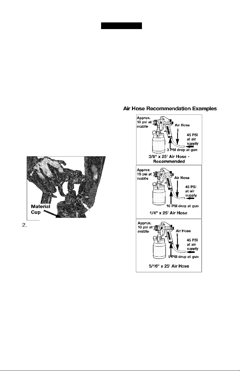
1. Attach air supply line to 1/4 NPT
air inlet. NOTE: A 3/8" diameter
air hose is recommended for the
best atomized air pressure. If
using a 1/4" or 5/16"diameter air
hose the air pressure must be set
at the regulator to allow for the
drop in air pressure from the
regulator to spray gun.
5- ENG
D297S3
Page 6
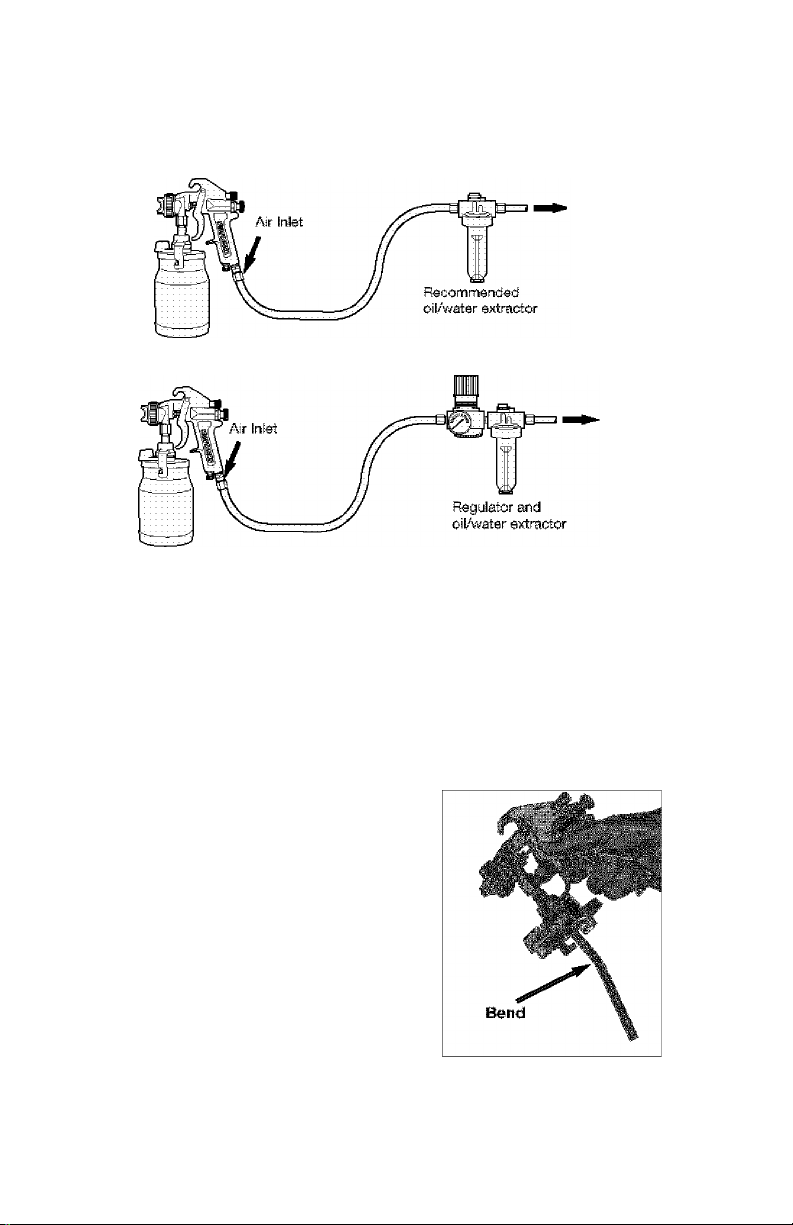
fWiPORTANT: The use Of a oil/wafer extractor is recommenOed. See set
illustrations for exampies.
Basic Set Up
. To Air Supply- ^
air compressor
ec|uipped with a
regulator
Ideal Set Up
To air supply hard plumbed
air supply
Before Using Spray Gun
ACAUTION
finishing materials- It is not
designed for use with corrosive or
highly abrasive materials. Using
these materials can lead to poor
performance and/or failure of this
product.
1, Mix materiai according the
manufacturer’s instructions.
Mixture should be smooth and
easily pourable. Lumps or foreign
particles should be removed by
straining through a suitable paint
filter, NOTE: Using a Sears
Viscosimeter will help In
measuring the viscosity or
thickness of the materiai.
For Siphon Feed Connection
1. Remove the material cup from
fid/gun assembly. NOTE: Slide
release lever to the right, rotate
fid, and remove materiai cup.
029783
This gun is designed
for use with most
2, Fill the material cup 3/4 full.
3, Attach materiai cup to the lid/gun
assembly and slide release iever
to the left to secure in place,
NOTE: When replacing lid/gun
assembly make sure bend in material
tube is positioned to the front of the
spray gun as shown.
4.
Attach air supply line to 1/4 NPT
air inlet.
See "Operation" Section to learn
5,
how to use the spray gun.
6- ENG
D29783
Page 7
To Convert to Remote Pressure
Feed
If the material to be sprayed is too
heavy for siphon feed or higher
volume application is desired, convert
to the pressure feed set up.
1.
Remove the material cup from
fid/gun assembly. NOTE: Slide
release lever to the right, rotate
fid, and remove material cup.
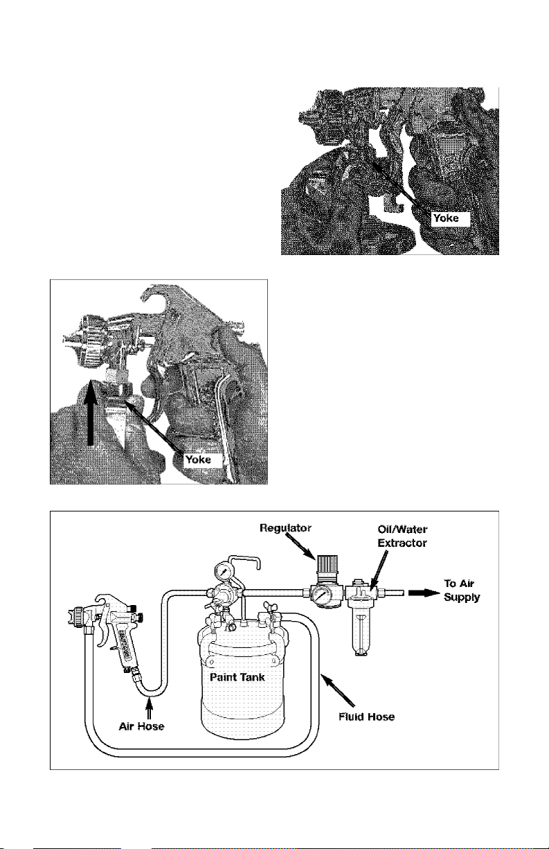
2.
Slide yoke, with built in socket
feature, over nut. Grip the yoke
and turn to loosen nut, after the
nut is loosened hand turn until lid
assembly can be removed from
gun.
3. The gun is now ready to be
connected to any pressure teed
tank with a standard 3/8" straight
pipe female connection. See
paint tank manufacturer's manual
for correct procedure,
4, See "Operation" Section to learn
how to use the spray gun,
NOTE: When replacing lid assembly to
gun assembly hand tighten nut and
then slide yoke over nut to tighten
securely.
Typical Pressure Feed Set Up
7- ENG
D297S3
Page 8
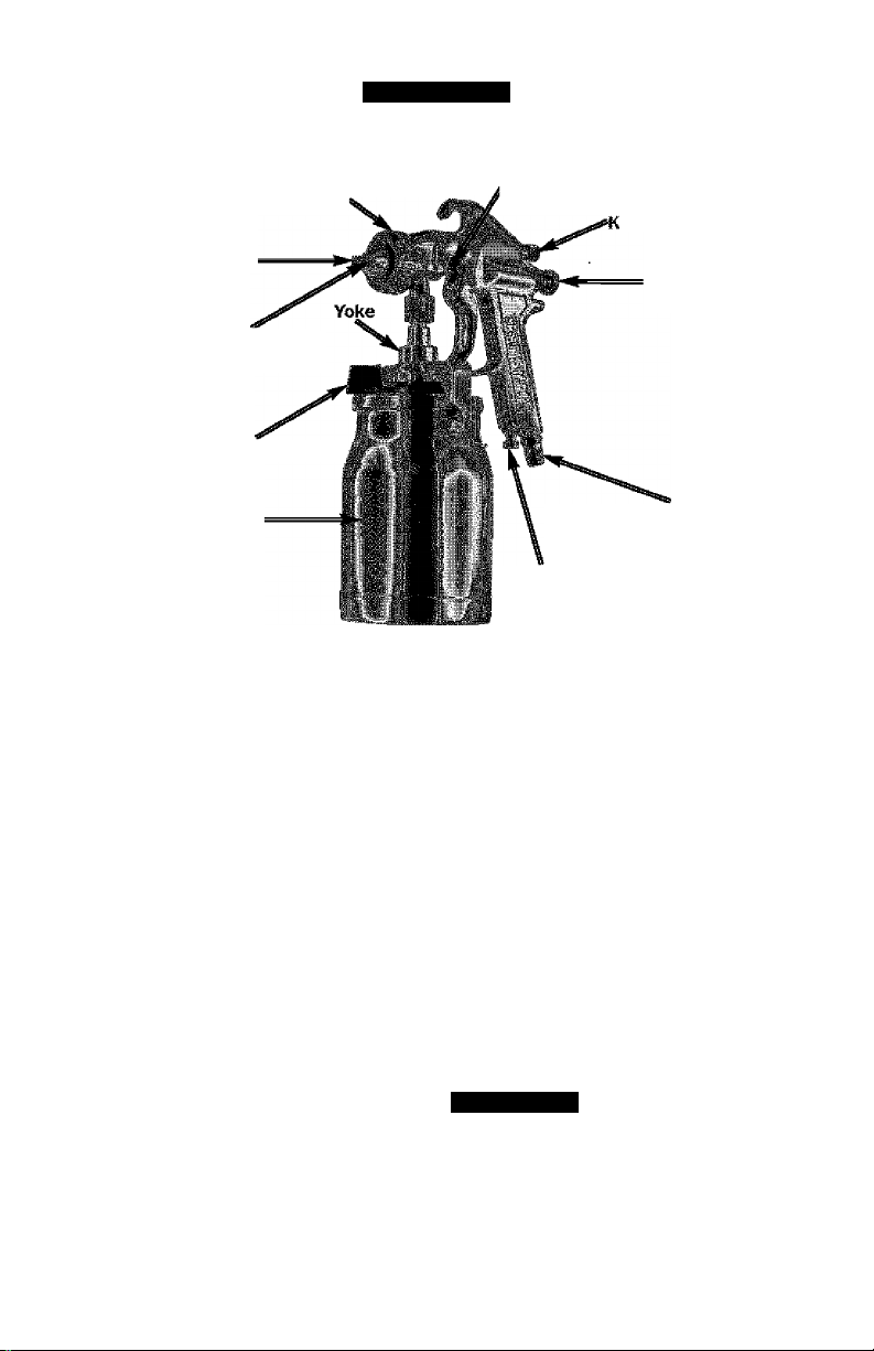
Know Your Spray Gun
OPERATION
Machined Brass
Externa! Mix CaP'
Air Cap Horns
Hardened Steel
Fluid Tip
Release Lever
1 - Quart
Siphon Feed
Material Cup
Machined Brass External Mix Cap -
The air and matersai are mixed after
¡eaving the nozzle to provide a
superior finish with thick and thin
matetial.
Hardened Steel Fluid Tip - for long
fife.
Air Cap Horns - determines a
horizontal or vertical spray pattern.
Fluid Con&ol Knob - controls the
fluid or density of fan spray.
Pattern Control Knob - controls the
size of the pattern from a large oblong
to small round pattern.
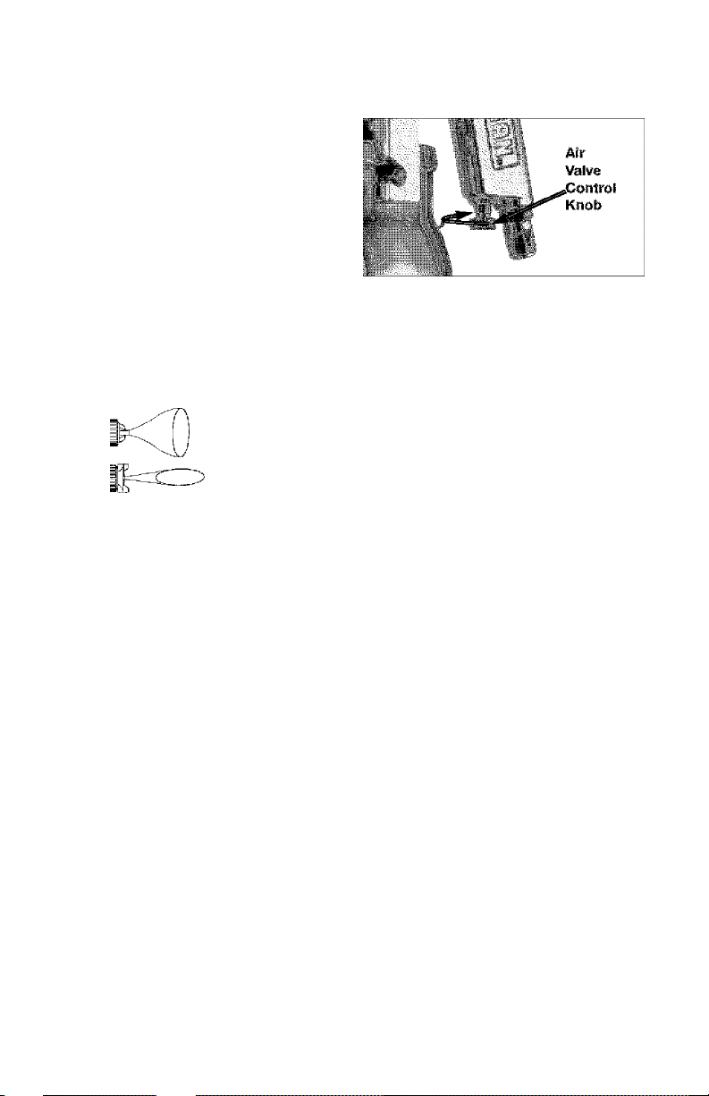
Air Valve Control Knob - fine tunes
the material spray with air.
1/4« isjp-f Inlet- allows the spray
gun to be connected to the air supply.
Release Lever - releases lid/gun
assembly from material cup.
Yoke - with built in wrench used to
easily remove gun from material cup
without tools.
Fluid Needle Adjustment Nut
Pattern Control
nob
Fluid Control
Knob
1/4" NPT Air Inlet
Air Valve
Control Knob
ACAUTION
I Before
I disassembly or re
moval of any part of gun or attached
components, shut off compressor,
release pressure by depressing
trigger, and disconnect power
source. NEVER assume system
pressure is zero!
ACAUTION
Prior to daily
operation, make
certain that all connections and fit
tings are secure. Check hose and all
connections for a weak or worn
condition that could render system
unsafe. All replacement components
such as hose or fittings must have a
working pressure equal to or greater
than system pressure.
AWARNING
TO AVOID CREATING
AN EXPLOSIVE
ATMOSPHERE, WORK ONLYfN
WELL VENTILATED AREAS.
029783
8- ENG
Page 9
AWARNING
USE OF A FACE
MASK ES
RECOMMENDED TO PREVENT ENHAU«-fON OF TOXEC MATERIAL.
Before Using Your Spray
Gun
1. Set up spray gun as described
in the "How to Set Up Spray
Gun" paragraph in the
“Assembly' section of this
manual.
To Use Spray Gun
1. The position of the air cap fioms
will deteimine the fan spray
pattern. Loosen air cap and rotate
horns to achieve desired pattern.
Tighten air cap.
Horizorstal position
Vertical position
2.
Turn fEuid control knob clockwise
until it stops, do not force. This
will shut off the fluid flow. NOTE:
The fluid or density of “tan spray”
is controlled by fluid control
knob.
Turn pattern conb'ol knob
3.
counterclockwise until first thread
is flush with gun body. NOTE: Air
flow is controlled by pattern con
trol knob.
ACAUTION
control knob counter clockwise after
first thread is flush with the gun
body. They are under pressure vrtien
the gun is triggered and could leave
the gun wilb force.
'^r ^Control
DO NOT turn pattern
control knob or fluid
first thread flush pattern
Knob
Ruid
^i^sponbol
Knob
4. Turn air valvo control knob
clockwise until it stops, do not
force.
5. Adjust air pressure to 40 psi at
regulator.
ACAUTION
ACAUTION
DO NOT exceed 45
psi.
Pressure may vary
according to
viscosity of material used. Maximum
working pressure of gun is 45 psi.
DO NOT EXCEED PRESSURE LIMIT
OF GUN OR ANY OTHER COMPO
NENT IN SYSTEM!
6. Depress spray gun trigger and
gradually turn the fluid control
knob counterclockwise until
desired fluid flow is reached.
Trigger gun quickly, one second
on-off to test pattern.
ACAUTION
NEVER point Spray
gun at self or any
other person. Accidental discharge
of material may result in serious
injury.
To adjust spray pattern and fluid
presaire:
• To adjust the fluid, turn fluid con
trol knob counterciockwise to in
crease or clockwise.
• To adjust the air flow, turn pattern
control knob counterclockwise to
increase or clockwise to de
crease.
• To fine tune the air flow, turn air
valve control knob counterclock
wise to increase, or clockwise to
decrease.
IMPORTANT: Always Clean gun after
each use. See 'Maintenance" section
for correct procedure.
9- ENG
D29783
Page 10
Operating Tips
• To reduce overspray and obtain
maxim um efficiency, always spray
with the lowest possible fluid/air
pressure.
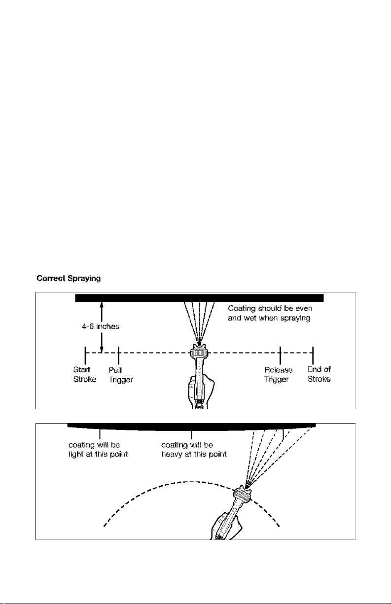
• Hoid the gun perpendicular to the
surface, 4" to 6" distance.
• Two thin coats will produce a
better finish than one heavy coat.
• Mask off areas not being
sprayed.
• Follow contour.
• Overlap each stroke 50%.
• Ends are feathered by triggering.
That is, begin stroke before
pulling frigger and releasing just
before ending the stroke.
• Spray edges and corners first.
This will reduce overspray while
providing good coverage on
corners.
Don’t arc strokes, move the gun
parallel to work.
Pattern should be
shaped as shown, if not
see "Troubleshooting"
section.
Care should be exer
cised when handling spray gun to
avoid damage to the orifice of the
air cap and tip of fluid nozzle.
Damage to these parts results in
irregular spray patterns.
Practice on a cardboard target to
make sure pattern size and
material consistency are correct
before spraying on actual project.
I
incoit^ct Spraying
029783
10-ENG
Page 11

MAINTENANCE
AWARNING
DO NOT ATTEMPT
TO UNCLOG (BACK
FLUSH) SPRAY GUN BY SQUEEZING
TRIGGER WHILE HOLDING FINGER
IN FRONT OF FLUID NOZZLE.
Always axarcisa axtreme care when us-
ing any solvent or thinner. Never
clean gun near fire, flame, or any
source of heat or sparks. Properly
dispose of used cleaning materials.
DO NOT soak entire
spray gun in solvent
or thinner for a long period of time
as this will destroy lubricants and
possibly make motion uneven. NEV
ER use lye or caustic alkaline solu
tion for cleaning. Such solutions will
attack aluminum alloy parts of gun.
Cleaning
IMPORTANT: Clean gun immediately
after use. Paint and other materials
dry quickly in the small passages.
1. Turn off air supply to gun,
2. Remove the material cup from
lid/gun assembly. NOTE: Slide
release lever to the right, rotate
lid, and remove material cup.
When using the remote pressure
feed method: See manufactuier’s
manual for suggested cleaning of
remote cup or tank.
3. Empty material from material cup
and replace with a suitable
cleaning solvent (see material
container for recommended
solvent).
4. Turn air supply on and operate
trigger until all material traces have
disappeared and gun is thoroughly
clean,
5. To prevent corrosion, fiii material
cup with mineral spirits. Turn air
supply on and operate trigger until
all traces of mineral spirits have
disappeared.
IMPORTANT: Do not immerse the
gun in solvent, this will cause
damage to the packings.
NOTE: Always comply with iocai codes
when disposing of solvents,
6. Remove air cap and immerse in a
suitable solvent. Use a bristfe
brush to clean dried paint and
blow if dry with compressed air.
7. Use a wooden toothpick to dean
small dogged holes,
IMPORTANT: DO NOT use hard
objects to clean clogged holes.
TTie smallest amount of damage
may cause irregular spray
pattern.
8. Wipe gun with a solvent soaked
cloth.
IMPORTANT: Make certain air cap
and fluid nozzle are kept clean at all
times.
Lubrication
Lubrication ptocedutes must be ob
served after thoioughîy cleaning the
gun to ensure effective, high quality
performance of spray gun.
1. Lubricate working points with
straight mineral oil, or castor oil,
2, Periodically, place a few drops of
oil on tapered sections of fluid
nozzle to ensure easy operation of
air cap.
Replace nozzle set
When changing nozzle set, make sure
the complete nozzle set is exchanged.
A set includes an air cap, fluid nozzle,
and fluid needle. NOTE: Assemble
fluid nozzle before fluid needle.
11-ENG
D29783
Page 12

TROUBLESHOOTING
NOTICE: See parts list to identify parts referred to in these Troubleshooting steps.
PROBLEM
Heavy right or ieft side
pattern
)(
Heavy top or bottom
pattern
u
Heavy center pattern
«
Spilt spray pattern
I
Spitting, Irregular or
fluttering spray
CAUSE
1, Dried material is
clogging sideport "A” and
causing side-port
“B" to blow spray
towards the
clogged side.
1, Dried material at
fluid nozzie “C"
restricts air flow.
2, Loose air
nozzie.
3, Air pressure too
high
1, Too much material.
2, Materia! too thick.
1. Air pressure too high.
2. Not enough material
1. Leak at thread of fluid
nozzie.
2. Leak at fluid needle.
3. Insufficient fluid in cup.
1. Soak side-ports in thinner to
1. Remove air nozzie. Wipe fluid
2. Fast^ nozzie securely.
3. Turn pattern control knob
1. Turn fluid control knob
2. Thin materid.
1. Turn pattern controi knob
2. Turn fluid control knob counter
1. Tighten fluid nozzie.
2. Tighten the fluid needle
3. Fiii cup with fluid.
CORRECTION
dean ciog, DO NOT poke any
opening with hard objects.
tip using a cioth soaked in a
suitabie solvent or a soft brush.
dockwise to reduce air
pressure.
dockwise to decrease materia!
flow or turn pattern control
knob counter clockwise to
increase air pressure.
dockwise to reduce air
pressure.
clockwise to increase material
flow.
adjustment nut.
029783
4. Vent hole in materia! cup
cover clogged (only in
siphon feed mode).
5. Materia! cup tilted at an
excessive angle,
6. Fluid too heavy for siphon
feed.
7. Loose fluid tip or dams^ed
tip seat
12-ENG
4. Ciean veit hole.
5. Do not tilt material cup
excessively or rotate fluid tube.
6. Thin materia! or convert to
remote pressure feed mode.
7. Tighten or replace.
Page 13

PROBLEM
Unatomized or
spattered spray
CAUSE CORRECTION
1. Material too heavy.
2. Insufficient air pressure.
1. Thin material.
2. Turn pattern control knob
counter clockwise to Increase
air pressure. Turn mt valve
control knob counter clockwise
to Increase air pressure.
3. Fluid pressure too high. 3. Turn fluid control knob
clockwise to decrease fluid
flow. If using in renote
pressure feed mode decrease
fluid pressure at paint tsnk.
4. Dried material on tip of
4. Clean.
fluid nozzle or air jets of
air cap.
Inadequate air
delivery
Excessive fog
Material leaking from
fluid inlet of cup.
Material leaking from
nozzle when trigger is
released
1. Air valve control knob
partially closed.
2. Dried material in air jets
or air cap.
3. Obstaiction in air Inlet.
1. Air pressure too high for
viscosity of fluid
2. Too far from work
surface.
1. Loose cup or foreign sub
stances oiVbeiween cup
thread aid fluid inlet.
1. Dried material In tip of
nozzle.
2. Loose fluid needle
adjustment nut.
1. Turn air valve control knob
clockwise to open.
2. Clean.
3. Remove obstaiction.
1. Reduce air pressure at air
supply regulator, turn pattern
control knob clockwise, or turn
fluid control knob counter
clockwise.
2. Adjust to proper distsnce.
1. Clean and tighten.
1. Ciean
2. Tighten fluid needle «tjustment
nut.
13-ENG
D29783
Page 14

PARTS LIST
Spray Gun Model Number 919.155190
KEY
RiUlTNO
NO.
1
SQ5-0056 Brass Ring Cap
2 SG5-0057
DESCRIPTION
Air Nozzle
3 SQ5-0058 Fluid Nozzte
4
SG5-0059
5 SG5-0060
Air Reducer
Washer
6 SG5-0061 Head
7 SG5-0062 Screw
SG5-0064
8
Trigger Rn
10 SG5-0066 Snap Ring
11
SG5-0063
12 SG5-0021
SG5-0012 0-Ring
13
14
SG5-0010 Air Valve Assembly
15 SG5-0016
SG5-0024 Retaining Nut
16
17
SG5-0023
Gun Body
Fluid Needle Assembly
Spring
Spring
18 SG5-0025 Fluid Needle
Adjusting Screw
19 SG5-0020 Valve ^em Assembly
SG5-0017 0-Ring
20
21
22
029783
SG5-0018
SG5-0019
O-Ring
0-Ring
KEY
NO. PART NO
SG5-0044
23
DESCRIPTION
Adapator 1/4 NPT X 1/4 NPS
24 X
----------
X
----------
25
26 X
--------
27 X
----------
28 SG5-0009
Regulator
Screw
O-Ring
Lock Ring
Peking Retainer
29 SG5-0003 Fluid Needle Packing
30 SG5-0013 Trigger
31 4.SG5-0035
32
4.SG5-0036
4.SG5-0037 Arm
33
34
4-SGE-15 Lever Release
35 4.SG5-0039
4-
36
Screw
Nut
Lid Cannister
SG5-0040 Gasket
37 4.SG5-0041 Siphon Tube
38
4-SG5-0042
• K-0189
Ganniste"
Gasket Kit.
4.K-0190 Compiete Cup
and Lid AssempSy
X SG5-0051
14-ENG
Regulator Kit
Page 15

CONTENIDO
Qsrantla............................................ ... .15
Definiciones de normas de seguridad
instrucciones importantesde
seguridad
..........................................
Especificaciones
Ensamblaje .......................................
................................
.,. .15
.16-17
___
.18-20
Operación
Mantenimiento
Diagnóstico de problemas .
Lista de partes
17
Como solicitar repuestos .. . .contratapa
..............................
.......................
........................
............
................
................
................
21-23
24
25
14
GARANTIA
ÜN ^0 DE GARANTIA COMPLETA SOBRE LA PISTOLA ROCIADORA
Si esta pistoia rociadera fejvíera fallas de materiales o fabricación dentro del año de su fecha de
compra, DEVUÉLVALA M.CEMTRO DE REPARACSONES DE SEARS MÁS CERCMIO DENTRO DE
LOS EE.UU., Y SEAñS LA REPARARÁ SÍN CARGO ALGUNO. SI SÉ HUBIESE COMPRADO EN
UNA FERRETERÍA ORCHARD, DEVUÉLVALA A LA FERETERA ORCFIARD MÁS CERCANA, Y
ORCHARD LA REPARARÁ SIN CARGO ALGUNO.
Si esta pistoia rociadera fuera utilizada para uso comercis^ o con pre^wsito de aiquiier, la garantía
tendrá vigencia solamente por nervente días a ptrHr de le fecha de compra.
Esta garantía !e etorga derechos legales específicos y usted podría tener otros derectos que v^fan
entre los estados.
Sears, Roebuck and Co., Hoffman Estates, IL $0179 EE.UU.
definiciones de normas de seguridad
Este manual corrtiaie información que es importante que usted sepa y aitienda Esta
Infomación se reladona con la protección de SU æGURIDAD y la PREVENCfÓN DE
PROBLEMAS AL EQUIPO. Para aleudarle a identificar esta informacíén usamos ios
siguiaites símbolos. Por favor leer este manual y prestar ataición especial a estas seccíaies.
indica una situación de
no se evita causará lesiones serias o
muerte.
AADVERTENCIA
poíenciaimente riesgosa, que si no se
evita podría causar lesiones serias o
muerte.
riesgo inminente que sí
Indica una
situación
APRECAUCIÓN
peligrosa, que sí no se evitada, podría
causar lesiones menores o moderadas.
APRECAUCiÓN
alerta, indica una situación potencialmente
riesgosa que si no se evita, podría caus^
daños en la propiedad.
15- SP
Indica una situación
potencialmente
Usado sin el símbolo
de seguridad de
D297S3
Page 16

ínstrucciones importantes de seguridad
• conserve estas instrucciones «
AADVERTENCIA
ENTENDER TODAS LAS ADVERTENCIAS SEGURIDAD E INSTRUCCIONES DE OPERACIÓN
ANTES DE USAR ESTA UNIDAD.
AADVERTENCIA
Riesgo do explosión o incendio - Materiales inflamables.
¿QUE PUEDE OCURRIR?
Rie$90 de explosif ^ Metálales iecompatibies ^M||v
¿QUÉ PUEDE OCURRIR?
Loa solventes 1,1 ^ TiicEofoetanos y Cloruro
de Metiíeno pueden reaccionar químicamente
con ei aluminio que se usa en la mayona de los
equipos de pulverización en esta pistola y en
este contenedor, y pueden genersv un riesgo de
explosión.
LA OPERACIÓN INAPROPIADA DE ESTA UNIDAD RJEES CAUSAR
LESIONES SERIAS Y DAÑCS A LA PROPIEDAD. L^RY
I Los sígo/entes riesgos pueden ocurrir durante el uso normal de esíe
I
producto:
RIESGOS
ÉÉi
Jm W
~ I
¿CÓMO PREVENIRLO?
liiiíiiili
RIESOO y 1
¿CÓMO PREVENIRLO?
Leer !a etiqueta u hoja de información del material
a pulverizar.
1 .Nunca usar tipo alguno de laca protectora
puiverizabie que ccsntanga estos solventes.
2. N0 usar estos solventes para limpiar ei equipo.
3. E11 caso de duda respecto a la conipatibiíidad
del material, oontactw al proveedor del material.
RIESOO
Riesgo de inhalación
¿QUÉ PUEDE OCURRIR?
RIESGO
RiesBO de objetos en suspensión aérea
¿QUÉ PUEDE OCURRIR?
Ciertas partes están prewrizadas cuando la
pistola está conectada a una línea de aire
presurizada y pueden SE^ir disparadas si se
desarma la pistola.
La exposición prolongada al chorro de mre puede
causar lesiones permanentes ai oído.
029783
¿CÓMO PREVENIRLO?
¿CÓMO PREVENIRLO?
Desconectar la pistola de la iínea de aire, o
despnesurizwla completamente cuEVido se vaya
a desamiar la pistola.
1 • . . 1 .'-J 1 '■-! I' i ! ' i 1 1 i -h" ^"r : í" ! í
iiÌgg:|BÌÌÌgÌ'iÈlìl#fSS^
Al operw un equipo para pulverizar siempre usar
protección para ios oídos.
16- SP
Page 17

Riesgo do inyección
RIESGO
¿OUÉ PUEDE OCURRIR? |
ESPECIFtCACIONES
¿CÓMO PREVENIRLO?
Presión mínima a la entrada de ia pistola
Presión máxima a la entrada de ia pistola
Conexión de aire
Conexión de líquidos
Contenedor de pintura
Tipo de aguja
Tipo de alimentación
Tipo de purga
Requisitos dei compresor de aire
20 PSI
45 PSI
Estándar 1/4 NPS
Estándar 3/8 NPS
946m!, de aluminio con boca ancha
Acero inoxidable
Sifón*
No se purga
8.6 Pie’/min a 40 PSi
* Esta pístoia pulverszadora puede convertirse fácilmente a alimentación por presión para
usarse con un tanque de pintura (se vende por separado) cuando se pulveriza material
pesado o para proyectos grandes.
17- SP
D29783
Page 18

ENSAMBLAJE
Contenido de la caja
1 - Pistola pulverízadora
1' Manuial del propietario
Cómo aimar
La pistola puiverizadora Craflsman se
despaciia compietanente ensamblada y
preparada para pulv«-izar alimentándose
por sifón.
Esta pistola fue tratada con un
anticorrosivo antes de su despacito, por lo
que antes de usarse debe lavarse
internamente con un solvente apropiado
(destilado mineral).
Para lavar ínternatnente la pistola antes
de su uso
Contened orde
ñ de seguro i
1. Desmontar el contenedor de la tapa
en la pistola. NOTA; Deslizar ía
palanca a ia derecha, rotar la tapa y
desprender ei contenedor.
2. Llenar 3/4 partes del contenedor con
un solvente adecuado.
3. Reinstalar el contenedor en la tapa en
la pistola y deslizar la palanca a la
izquierda para asegurar el
contenedor.
4. Conectar la línea de suministro de
aire al conector de 1/4" NPT.
Referirse al párrafo "Conexión" en
esta sección.
5. Apretar el gatillo para disparar el
solvente y que pase por la pistola.
Referirse al párrafo "Como usar la
pistola puiverizadora’ en la sección
"Operación" de este manual,
6. Pulverizar iodo el solvente hasta que
se agote y evacuar cualquier residuo
del contenedor.
Como conectar la pistola puiverizadora ai suministro do aire
1. Conectar la linea de suministro de
aíre al conector de entrada de 1/4'
NPT. NOTA: Para la mejor presión de
aíre para pulverizar, se recomienda
usar una manguera de 3/8" de
diámetro. SI se usa una manguera de
aire de 1/4" ó 5/16" de diámetro, la
presión de aíre debe graduarse en el
regulador para compensar por la
caída de presión de aire entre el
regulador y la pistola puiverizadora.
Ejemplos do rocomondaciones para manguera do aire
de arre en ^ pistola 3 PSI
Manguera de air^ de
X 7,6m {25')
Caída aír^ en la pistola P$l
Mangu^^ de aire de
1/4" X 7,Sm (25‘)
Calda ce aire en la pídola P$l
Manguera de aire de
5/16”x7,Snri(25*)
029783
18™ SP
Page 19

IMPORTANTE: Se recomienda usar un extractor de aceíte/agua. Ver los ejemplos en las
ilustraciones.
Configuración básica
- A la línea de
sumifiietro de aire
(Un compresor
equipado oca un
regulador)
Configuración ideai
A la linea de
^suministro de
aire (con c^'da
fuerte de
presídn)
Antes de usar ia pistoia puiverizadora
APRECAUCIÓN
usarse con la mayoría de materiales para
acabados que no sean corrosivos o
altamente abrasivos; ya que éstos
producirfan un mai rendimiento y/o la
falla de la pistola.
1. Mezclar ^ material siguiendo las
insírucciones del fabricante. La mezcla
debe queclíT sin grumos y debe poderse
vaciar fécilmaite. Deben ^iminírse los
grumos y partículas extrañas colándose
con un filíro de pintura adecuado,
NOTA: El uso de un medidor de
vi^ostdad de Sears ayudírá medir !a
vlKioadad o espesor del matetal.
Esta pistola está
diseñada para
Para conexión con alimentación por sifón
1. Desmontar el contenedor de la
pistola. NOTA: Deslizar la palanca a
ía derecha, rotar ia tapa y desprender
el contenedor.
2. Llenar 3/4 partes del contenedor con
un solvente adecuado.
3. Reinstaiar el contenedor en la tapa en
la pistola y desilzar la palanca a ia
izquierda para asegurar el
contenedor.
NOTA: Al reinstalar la pistola, cerciorarse
que el doblez en el tubo del sifón quede
hacia el trente de !a pistola como se
muestra.
4,
Conectar ia línea de suministro de
aíre al conector de 1/4* NPT,
Para aprender a usar la pistola
puiverizadora, referirse a la sección
"Operación".
13- SP
D29783
Page 20

Para convertir a alimentación remota a presión
Sf ei material a pulverizase fuese muy
pesado para aiimentactón por sifón o se
desea aplicar una mayor cantidad de
volumen:
1.
Desmontar el contenedor de la
pistola NOTA: Deslizar la palanca
a la derecha, rotar !a tapa ^ la
pistola y despreider ei contenedor.
2.
Deslizar el yugo con e! adaptador
incorporado sobre la tuerca Agarra
el yugo y girarlo para aflojar la tuerca
y girar a mano hasta que el conjunto
de la tapa pueda sacarse de la
pistola
3. Ahora la pistola está lista para
conectarse a cualquier tanque para
ailmeníadón a presión con un niple
hembra, estándar recto de 3/8“, Para
e! procedimiento correcto, referirse al
manua! del fabricante del tanque.
4. Referirse a !a sección "Operación"
para aprender a usar la pistola
pulverízadora.
NOTA: Al reinstalar el conjunto de ía tapa
en la pistola, ajustar a mano la tuerca y
deslizar el yugo sobre la tuerca para
ajustarla firmemente.
Configuración típica alimentación remota a presión
029783
20" SP
Page 21

OPERACIÓN
Familiarización con la pistola pulverizadora
Tapa mezcladora exterior
de latón maquinado
Aletas de la
tapa de aire
Boquilla de liquido
de acero endurecido
Palanca de seguro
Contenedor de
material de a46ml
(1/4 de Gal.) con
de alimentación
por sifón
Tapa mezcladora exterior de latón
maquinado. El aire y el material se
mezclan después de salir por la boquilla
para proveer un acabado superior con
materia! grueso o fino.
Boquilla de acero endurecido para
liquido para una vida útil más larga.
Aletas de la tapa de aíre para seleccionar
entre un patrón de rociado (Abanico)
horizontal o vertical.
Perilla de control del flujo. Controla la
fluidez o densidad de! abanico de rociado.
Perilla de control del patrón de rociado
(Abanico) Controla el tamaño del patrón
de rociado o abanico desde una forma
larga ovoide hasta un un circulo pequeño.
Perilla de control la válvula de aire para
hacer el ajuste fino de la mezda de
material pulverizado con el aire.
Conector roscado de 1/4" NPT рш'а la
línea de suministro de aire.
Palanca de seguro. Suelta o asegura el
contenedor a la tapa en la pistola.
Yugo con llave incorporada que se usa
para separar el contenedor fácilmente de
la t^a en la pistola.
tuerca reguladora de
la aguja de líquido
Perilla de control de
patrón de rociado
(Abanico)
Perilla de control
del flujo
or roscado
de 1/4“ NPT para
entrada de aire
Válvula de aire
Antes de desarmar
cualquier pieza a la pistola o
componentes instalados, apagar el
compresor, despresurizar apretando el
gatillo y desconectar de la ftjente de
energía. ¡NUNCA asumir que el sistema
está despresurizado (presión cero).
APRECAUCIÓN
cerciorarse que todas ¡as conexiones y
acoples estén apretados firmemente.
Inspeccionar la manguera y todas las
conexiones para detectar si hay partes
débiles o gastadas que puedan volver ei
sistema inseguro. Todos los
componentes de repuesto como
mangueras o acoples deben tener una
capacidad de trabajo igual o mayor a ia
presión del sistema.
AADVERTENCIA
ATMÓSFERA EXPLOSIVA, TRABAJAR
SÓLO EN ÁREAS BIEN VENTILADAS.
o de sacarle
Antes de ia
operación diaria,
PARA EVITAR
CREAR UNA
21- SP
D297S3
Page 22

EZ
MASCARA PROTECTORA PARA EViTWl
INHALMt MATERIAL£S TÓXICOS.
SE RECOMi£^JDA
USAR UNA
^tes de usar la pistola
pulverizadora
í. Armarla orno se indica en el páirafo
"Armado de la pistola pulverizadora"
en la sección "Ensamblaje".
Para usar la pistola pulverizadora
1. La posición de las atetas de la tapa
de aire determina e! patrón del
abanico de rociado. Aflojar ía tapa de
aire y girar las atetas para obtener el
patrón deseado. Volver a ajustar la
tapa de aíre.
Posiciótr horizontal
Posición v^ioa!
Cortar el flujo girando la perilla de
control del flujo en ei s^tído del
reloj hasta que el flujo se detenga, sin
forzar. NOTA: La fluidez o densidad
del abanico de rociado se controla
con la perilla de control del flujo.
Girar la perilla de conbol de patrón
contra el sentido del reloj hasta que
la primera vuelta de la rosca esté a
ras con el casco de la pistola. NOTA:
El flujo de aire se controla con la
pallia de control del patrón.
APRECAUCIÓN
pabón ni la del control de fluido contra el
sentido del reloj después que ía primera
vuelta de las roscas estén a ras con el
casco de la pistola; porque están
pie^irizadas cuando se aprieta el gatillo
y podrian salir disparadas con fuerza.
No girar ia p^lla
de control del
4. Girar la perilla de ia váivuía de aire en
el sentido del reta] hasta que se
detenga, no forzarla.
Perilla de
control de
la válvula
de aire
5. Graduar el regular para una presión
de aire de 40 PSI.
APRECAUCIÓN
a la viscosidad del material utilizado. La
presión máxima de trabajo de la pistola
es 45 PSI. ¡NO EXCEDER EL LÍMITE DE
PRESIÓN DE LA PISTOLA N! DE
COMPONENTE ALGUNO DEL SISTEMA!
6. Apretar ei gatillo y gír^ gradualmente
!a perilla de control de fluido contra el
sentido del reloj hasta lograr el flujo
de líquido deseado. Probar el patrón
(abanidoj de rociado, apretar el gatillo
con una intermitencia de un segundo.
APRECAUCIÓN
pulverizadora a si mismo ni a otras
personas porque una descarga
accidental podría causar lesiones
serías.
NO exceder 45 PSI.
La presión puede
variar de acuerdo
Nunca apuntar la
pistola
Para regular el patrón de rociado y
presión de fiuido:
• Para regular la presión del líquido,
girar la perilla de control de fluido
contra el sentido del reta] para
aumentarla o en el sentido del reioj
para disminuirla.
• Para regular el flujo de aire, girar la
perliia de control del flujo de aire
contra el sentido del reioj para
aumentarla o en el sentido del reta]
para disminuirla.
• Para la regulación fina dei flujo de
aire, girar ía válvula de control de aire
contra el sentido del reioj para
aumentarlo o en el sentido del reioj
para disminuirlo.
IMPORTANTE: Siempre limpiar la pistola
después de cada uso. Referirse a la
sección “Mantenimiento“ para el
procedimiento correcto.
029783
22- SP
Page 23

Consejos prácticos:
• Para evitar pulverizar exceso y
iograr el máximo de eficiencia,
siempre pulverizar con la combinación
de presión de pintura y aire más baja
posibie.
• Sostener ia pistoia
perpendiculatmeníe a ia superficie a
una distancia de 10 a 15 cm (4" a 6")
de distancia.
• Dos capas deigadas producen un
mejor acabado que una c^a gruesa.
• Enmascarar ias áreas que no se van a
rociar.
• Seguir el contorno de ia supwticie,
• Trasiapar cada nuevo pase 50% sobre
el anterior,
• Ei movimiento del pase debe
empezarse antes de apretar ei gatilio y
el gatilio debe soltarse antes de
twminar el pase.
• PuSverizar los bordes y esquinas
primero. Esto reducirá el exceso de
pulvOTzado, asi como también
proveerá de un buen recubrimiento en
las esquinas.
Aplicación correcta:
No arquear las pasadas, mover ia
pistola en forma paralela a ia
superficie de trabajo durante toda la
pasada.
E! patrón de puíverizado
normalmente debe tener la
fotma mostrada; de io
contrario ver ia sección
"Diagnóstico de
Problemas”.
Tratar la pistola pulverizadora con
cuidado para evitar dañar ei orificio de
ia tapa de aire y de la boquília; porque
si se dañan, se producirán patrones
de pulv№zac¡ón irregulares.
Practicar sobre un cartón para
asegurarse de lograr el tamaño del
patrón de rociado (abanico) cerreto y
ia consistencia de material adecuada
antes de pintar la rociar la superficie
definitiva.
23- SP
D297S3
Page 24

MANTENIMIENTO
AADVERTENCIA
PISTOLA APRETANDO EL GATILLO Y
TAPANDO LA BOQUILLA CON EL DEDO.
APRECAUCIÓN
cuando se usen solventes o diluyentes.
Nunca limpiar o lavar la pistola cerca de
fuego, llamas ni fuentes de calor o
chispas. Desechar apropiadamente ios
materiales usados en la limpieza o
lavado.
APRECAUCIÓN
por largo Uempo porque se destruirá su
lubricación y posiblemente su
accionamiento se vuelva irregular.
NUNCA usar lejía ni soiuciones alcalinas
al limpiar (lavar) la pistola porque esas
soiuciones atacan las piezas de aleación
de aluminio.
Limpieza o Lavado
IMPORTANTE: Limpiar (lavar) la pistola
inmediatamente después de cada uso.
La pintura y otros materiales se secan
rápidamente en los pasajes pequeños.
1. Cortar e! suministro de aire a la
pistola.
2. Desconectar el contenedor de
material de la tapa en ía pistola
NOTA; Deslizar !a palanca a la
derecha, rotar la tapa en la pistola
y desprender el contenedor. Cuando
se use el método de aiimentación
remota a presión, referirse ai manual
del fabricante para las sugerencias de
limpieza (lavado) del contenedor o
tanque.
3. Vaciar eí material del contenedor y
reemplazarlo con un líquido solvente
adecuado (para el solvente apropiado,
referirse a la etiqueta del envase del
material).
4. Abrir el suministro de aire y apretar el
gatillo hasta que desaparezca toda
traza dei material y la pistoia quede
completamente limpia,
5. Para evitar la corrosión. Henar eS
contenedor con un destilado
mineral.Abrir el suministro de aire
y apretar el gatülo hasta que
desaparezca toda traza del destilado
mineral.
NO fNTENTAR
DESATORAR LA
Siempre tener
extremo cuidado
No sumergir la
pistola en solventes
IMPORTANTE; No sumergir la pistola en
el solvente porque las empaquetaduras
se dañarán.
NOTA: Siempre acatar ios códigos locales
^ desechar los solventes,
6. Sacar ia tapa y sumergirla en un
solvente adecuado. Usar una escobilla
de cerdas para limpiar la pintura seca
y soplarla con aire comprimido,
7. Usar un paüílo escarbadientes de
madera para ümpiar las obstrucciones
de ios orificios pequeños.
IMPORTANTE; No usar objetos duros
para limpiar las obstrucciones de los
orificios, porque el daño más leve puede
causar un patrón irregular de rociado.
8. Limpiar la pistola frotándola con un
paño empapado en soívente,
IMPORTANTE; Cerciorarse de manterter
siempre limpias la tapa de aire y la
boquilla para liquides.
Lubricación
Para asegurarse de mantener la calidad del
^to rendimiento de la pistola puiverizadora,
después de cada limpieza (lavado)
completo, siempre seguir el procedimiento
de íubrteación.
1. Lubricar los puntos de movimiento
con aceite minerai puro o aceite de
castor.
2. .i^licar periódicamente unas gotas de
aceite en las secetanes ahusadas de ía
boquiíia para líquidos para asegurar su
ftincionamiento ftoii de la tapa de aire.
Reemplazo del conjunto de la boquilla
Cuando se cambie eí conjunto de ía
boquilla, cerciorarse de cambiar todos sus
componentes. Eí conjunto está compuesto
por ¡a tapa de aíre, ia boquilla para líquidos
y la aguja para líquidos. NOTA: Ensamblar
la boquilla para líquidos antes que la aguja
psra líquidos.
029783
24- SP
Page 25

DIAGNÓSTICO DE PROBLEIVIAS
NOTA: Referirse a la lista de partes para identificar !as piezas a fas que se hace
PROBLEMA
Patrón grueso en el lado
izquierdo 0 derecho.
)(
Patrón grueso arriba o
abajo.
u
Patrón grueso en el
á
f
Patrón angosto en ei
ceitro.
La pistola escupe o
patrón Irregular,
tembloroso u onduiado
EN8
CAUSA
1, Material seco a
obstruyendo el ¡
orificio de salida
del lado "A"
haciendo que el l ^ )|
orificio del lado
"B” pulverice \
hacia el lado ¿
obstruido.
1, Material seco en
!a boquilla de ^
ílquidos "C" está
restringiendo el /
flujo de aire.
2, Boquillas de aire f©
suelta.
Av^
3, Presión de aire
demasiado alta
1, Demasiado material.
2. Material demasiado
espeso.
1. Demasiada presión de
are
2. Insuficiente material
1, Fuga en la rosca de la
boquilla para fluido
2, Fuga en la aguja para fluido
3. Material insuficimte en ei
contenedor.
4. Ortfiob de r^praoH^ en la
tapa d^ contenedor de
matQ-ial está obstruida (séío
ai modalidíKí de síf<^).
5. Contenedor de material
inclinado en demasiado
ángulo.
6. Liquido demasiado espeso
0 pesado para el tubo del
sifón.
7. Boquifla para fluido suelta
0 con el asiento dañado.
CORRECCIÓN
1. Sumergir las boquillas de
ambos lados en solvente ¡implo
para desatorarlas. NO usar
objetos duros para limpiar los
orificios.
1. Sacar la boquilla de aire y
limpiarla frotándola con una tela
empapada con un solvente..,
adecuado o con una escobilla
de cerdas blandas
2. Ajustar bien la tapa de la
boquiila,
3. Reducir la presión de aire
girando la perilla de control del
patrón de rociado ^ ei sentido
del reiol.
1. Reducir el flujo de líquido
girando la periila de control de
fluido en er sentido del relo o
aumentar la presión de aire
girándola tóriiia de control del
paírón (AMnicol contra el
2. Adelgazar el material.
1. Reducir la presión de aire
girando la perüia de control del
patrón de rociado (Abanico) en
eí sentido del reioj.
2. Aum«itar ei flujo de material
girando la p^ilia de control de
fluido contra el reloj
1. Ajustar la boquilla para fluido..
2. Ajustar la tuerca de ía aguja
para fluidos.
3. Reifenar el contenedor con
líquido
4. Limpiar ei orificio de respiración
5. No inclinar excesivamente o
girar el tubo de succión.
6. Adelgazar el material o cambisr
a modalidad de alimentación
remota por presión
7. Ajustar 0 cambiar.
25- SP
D29783
Page 26

PROBLEMA CAUSA
Matwal rociado no
1. Material demasiado
pulverizado o
salpicado.
2. Presión de aire
3. Presión de fluido
4. Material seco en el
Salida de aire
1. Perilla de control de ia
inadecuada.
2. Materia seco en !os
pesado o espeso
insuficiente.
demasiado alta.
orificio de la boquiiía de
fluido 0 fugas de aire por
la tapa de aire.
válvula de aire
parcialmente cerrada.
orificios de salida de are
0 la tapa de aire.
CORRECCIÓN
1. Adelgazar el material.
2. Aumentar la presión de aire
girando !a pOTila del patrón
(Abanico) contra el sentido de!
reloj. Aumentar la presión de
aire girando !a perilla de la
válvula de aire contra el
sentido del reloj,
3. Reducir e! flujo de liquido
girando la perilla de control del
flujo en el sentido del reloj. Si
se está usando con
alimentación remota a presión,
disminuir la presión del iíquido
en e! tanque de pintura.
4. Limpiar.
1, Abrir la perilla de control de !a
válvula de aíre girándola en el
sentido del reloj
2, Limpiar.
Nebulización excesiva.
Fuga de material por !a
entrada de! contenedor.
Fuga de material por la
boquilla cuando se
suelta ei gatillo.
029783
3, Obstrucción en la entrada
de aire.
1. Demasiada presión de
aire para la viscosidad
de! liquido.
2. Aplicación desde muy
lejos de ia superficie.
1. El contenedor está suelto
0 hay substancias
extrañas entre la rosca
de! contenedor y la
entrada de líquido.
1. Material seco en el orificio
de la boquilla
2. La tuerca de ajuste de la
aguja de fluidos está
suelta.
26- SP
3, Eliminar ia obstrucción.
1. Reducir la presión de aíre en el
r^ulador, girando ia perilla de
control del patrón en e! sentido
del reloj o girando !a periíia de
control de fluido contra el
seitido de! reloj.
2. Aplicar desde una distancia
adecuada.
1. Limpiar y ajustar.
1. Limpiar
2. Ajustar ia tuerca de ajuste de ia
aguja de fluidos.
Page 27

NOTES
27- SP
D29783
Page 28

NOTES
029783
28- SP
Page 29

NOTES
23- SP
D29783
Page 30

NOTES
029783
30" SP
Page 31

NOTES
31- SP
D29783
 Loading...