

Page 1
Owner’s Manual
SNOW THROWER
1450 Series Briggs and Stratton Engine
Power-Propelled
30" Two-Stage
Model No.
917.881064
Espanol, p. 21
CAUTION:
Read and follow all
Safety Rules and Instructions
before operating this equipment
Sears, Roebuck and Co., Hoffman Estates, IL 60179 U.S.A.
Visit our Craftsman website: www.sears.com/craftsman
Page 2

IMPORTANT
Safe Operation Practices for Walfc-Behind Snow Throwers
This snow thrower is capabie of amputating hands and feet and throwing objects,
Faiiure to observe the foiiowing safety instructions couid resuit in serious injury.
Look for this symbol to point out Im
portant safety precautions. It means
A
A
A
CAUTION!!! BECOMEALERT!!! YOUR
SAFETY IS INVOLVED.
WARNING: Always disconnect spark
plug wire and place It where It cannot
contact plug In order to prevent acci
dental starting when setting up, trans
porting, adjusting or making repairs.
WARNING: This snow thrower Is for
use on sidewalks, driveways and other
ground level surfaces. Caution should
be exercised while using on sloping sur
faces. Do not use snow thrower on
surfaces above ground level such as
roofs of residences, garages, porches
or other such structures or buildings.
Training
Read, understand and foiiow aii instructions on the
machine and in the manuai(s) before operating this
unit. Be thoroughiy famiiiar with the controis and the
proper use of the equipment. Know how to stop the
unit and disengage the controis quickiy.
Never aiiow chiidren to operate the equipment. Never
aiiow aduits to operate the equipment without proper
instruction.
3, Keep the area of operation ciear of aii persons, par-
ticuiariy smaii chiidren,
4, Exercise caution to avoid siipping or faiiing, especiaiiy
when operating the snow thrower in reverse.
Preparation
1, Thoroughiy inspect the area where the equipment is
to be used and remove aii doormats, sieds, boards,
wires, and other foreign objects,
2, Disengage aii ciutches and shift into neutrai before
starting the engine (motor),
3, Do not operate the equipment without wearing adequate
winter garments. Avoid ioose fitting ciothing that can
get caught in moving parts. Wear footwear that wiii
improve footing on siippery surfaces,
4, Handle fuei with care; it is highiy fiammabie
(a) Use an approved fuei container,
(b) Never add fuei to a running engine or hot en
gine,
(c) Fiii fuei tank outdoors with extreme care. Never fiii
fuei tank indoors,
(d) Never fiii containers inside a vehicie or on a truck
or traiier bed with a piastic iiner, Aiways piace
containers on the ground, away from your vehicie,
before fiiiing,
(e) When practicai, remove gas-powered equipment
from the truck or trailer and refuel it on the ground.
If this is not possibie, then refuei such equipment
on a traiier with a portabie container, rather than
from a gasoiine dispenser nozzie.
WARNING: Snow throwers have ex
posed rotating parts, which can cause
severe Injury from contact, or from ma
terial thrown from the discharge chute.
A
A
A
(f) Keep the nozzie in contact with the rim of the fuei
(g) Replace gasoline cap securely and wipe up spilled
(h) If fuel is spilled on clothing, change clothing im
5, Use extension cords and receptacles as specified by
the manufacturer for all units with electric drive motors
or electric starting motors,
6, Adjust the collector housing height to clear gravel or
crushed rock surface,
7, Never attempt to make any adjustments while the
engine (motor) is running (except when specifically
recommended by manufacturer),
8, Always wear safety glasses or eye shields during op
eration or while performing an adjustment or repair to
protect eyes from foreign objects that may be thrown
from the machine.
Keep the area of operation clear of all
persons, small children and pets at all
times Including startup.
CAUTION: Muffler and other engine
parts become extremely hot during
operation and remain hot after engine
has stopped. To avoid severe burns on
contact, stay away from these areas.
,4
WARNING: Engine exhaust, some of
Its constituents, and certain vehicle
components contain or emit chemi
cals known to the State of California
to cause cancer and birth defects or
other reproductive harm.
tank or container opening at aii times, until refuel
ing is complete. Do not use a nozzle lock-open
device,
fuel,
mediately,
Operation
1, Do not put hands or feet near or under rotating parts.
Keep clear of the discharge opening at all times,
2, Exercise extreme caution when operating on or cross
ing gravel drives, walks, or roads. Stay alert for hidden
hazards or traffic,
3, After striking a foreign object, stop the engine (motor),
remove the wire from the spark plug, disconnect the
cord on electric motors, thoroughly inspect the snow
throwerfor any damage, and repair the damage before
restarting and operating the snow thrower,
4, If the unit should start to vibrate abnormally, stop the
engine (motor) and check immediately for the cause.
Vibration is generally a warning of trouble,
5, Stop the engine (motor) whenever you leave the oper
ating position, before unclogging the collector/impeller
housing or discharge chute, and when making any
repairs, adjustments or inspections.
Page 3

6, When cleaning, repairing or inspecting the snow thrower,
stop the engine and make certain the collector/impeller and all moving parts have stopped. Disconnect
the spark plug wire and keep the wire away from the
plug to prevent someone from accidentally starting the
engine,
7, Do not run the engine indoors, except when starting
the engine and for transporting the snow thrower in or
out of the building. Open the outside doors; exhaust
fumes are dangerous,
8, Exercise extreme caution when operating on slopes,
9, Never operatethe snow thrower without proper guards,
and other safety protective devices in place and work
ing.
10, Never direct the discharge toward people or areas
where property damage can occur. Keep children and
others away,
11, Do not overload the machine capacity by attempting
to clear snow at too fast a rate,
12, Never operate the machine at high transport speeds
on slippery surfaces. Look behind and use care when
operating in reverse,
13, Disengage power to the collector/impeller when snow
thrower is transported or not in use,
14, Use only attachments and accessories approved by
the manufacturer of the snow thrower (such as wheel
weights, counterweights, or cabs),
15, Never operate the snow thrower without good visibility
or light. Always be sure ofyourfooting, and keep a firm
hold on the handles. Walk; never run,
16, Never touch a hot engine or muffler.
Clearing a Clogged Discharge Chute
Hand contact with the rotating impeller inside the discharge
chute is the most common cause of injury associated with
snow throwers. Never use your hand to clean out the dis
charge chute. To clear the chute:
1, SHUT THE ENGINE OFF!
2, Wait 10 seconds to be sure the impeller blades have
stopped rotating.
3, Always use a clean-out tool, not your hands.
Maintenance and Storage
1, Check shear bolts and other bolts at frequent intervals
for proper tightness to be sure the equipment is in safe
working condition,
2, Never store the machine with fuel in the fuel tank
inside a building where ignition sources are present
such as hot water heaters, space heaters, or clothes
dryers. Allow the engine to cool before storing in any
enclosure,
3, Always refer to operator’s manual for important details
if the snow thrower is to be stored for an extended
period,
4, Maintain or replace safety and instruction labels, as
necessary,
5, Run the machine a few minutes after throwing snow
to prevent freeze-up of the collector/impeller.
TABLE OF CONTENTS
SAFETY RULES
PRODUCT SPECIFICATIONS
CUSTOMER RESPONSIBILITIES
WARRANTY......................................................................4
ASSEMBLY / PRE-OPERATION
OPERATION
............................................................
.........................................
...................................
..................................
................................................................
2-3
6-8
9-14
MAINTENANCE.........................................................15-16
4
4
MAINTENANCE SCHEDULE
.........................................
15
SERVICE AND ADJUSTMENTS...............................17-19
STORAGE.......................................................................19
TROUBLESHOOTING
....................................................
20
REPAIR PARTS.........................................................40-65
SEARS SERVICE.......................................BACK COVER
Page 4

LIMITED 2-YEAR WARRANTY ON CRAFTSMAN SNOW THROWER
When used and maintained according to the operator’s manuai instructions, if this snow thrower faiis due to a
defect in matehai or workmanship within two years from the date of purchase, caii 1-800-4-MY-HOME® to arrange
for free repair.
During the first 30 days of purchase, there wiii be no charge to service the product in your home. For your
convenience, in-home warranty service wiii stiii be avaiiabie after the first 30 days of purchase, but a trip charge
wiii appiy. This charge wiii be waived if you transport the product to an authorized Craftsman drop-off iocation. For
the nearest authorized iocation, caii 1-800-4-MY-HOME®,
Warranty coverage does not inciude:
• Expendabie items that become worn during normai use, inciuding but not iimited to spark piugs, shear pins, beits,
• Standard maintenance servicing, oii changes, or tune-ups,
• Tire repiacement or repair caused by punctures from outside objects, such as naiis, thorns, stumps, or glass,
• Repairs necessary because of operator abuse, including but not limited to damage caused by impacting objects
that bend the frame, crankshaft or auger, or over-speeding the engine,
• Repairs necessary because of operator negligence, including but not limited to damage caused by improper
storage, failure to use the proper grade and amount of engine oil, or failure to maintain the equipment according
to the instructions contained in the operator’s manual
• Engine (fuel system) cleaning or repairs necessary because of fuel determined to be contaminated or oxidized
(stale). In general, fuel should be used within 30 days of its purchase date,
• Normal deterioration and wear of the exterior finishes, or product label replacement.
This warranty applies for only 90 days if this product is used for commercial or rental purposes.
This warranty applies only while this product is within the United States,
This warranty gives you specific legal rights, and you may also have other rights, which vary, from state to state.
Sears, Roebuck And Co., Hoffman Estates, IL 60179
CONGRATULATIONS on your purchase of a new snow
thrower. It has been designed, engineered and manufac
tured to give best possible dependability and performance.
Should you experience any problem you cannot eas
ily remedy, please contact your nearest Sears Parts &
Repair Center, We have competent, well-trained tech
nicians and the proper tools to service or repair this unit.
Please read and retain this manual. The instructions
will enable you to assemble and maintain your snow
thrower properly. Always observe the “SAFETY RULES”,
SERIAL NUMBER:
DATE OF PURCHASE:
THEMODELANDSERIALNUMBERSWILLBE FOUND
ONADECALATTACHEDTOTHEREAROFTHESNOW
THROWER HOUSING,
YOU SHOULD RECORD BOTH SERIALNUMBER AND
DATE OF PURCHASE AND KEEP IN A SAFE PLACE
FOR FUTURE REFERENCE,
PRODUCT SPECIFICATIONS
Gasoline Capacity 3,0 Quarts
and Type: Unleaded Regular only
Oil Type SAE 5W-30 or 10W-30
(API SG-SL): Synthetic SAE 5W-30
Oil Capacity: 18 Ounces
Spark Plug: Champion RJ19LM
Gap: 0,030"
CUSTOMER RESPONSIBILITIES
• Read and observe the safety rules,
• Follow a regular schedule in maintaining, caring for
and using your snow thrower,
• Follow the instructions under “Maintenance” and “Stor
age” sections of this owner’s manual.
Page 5
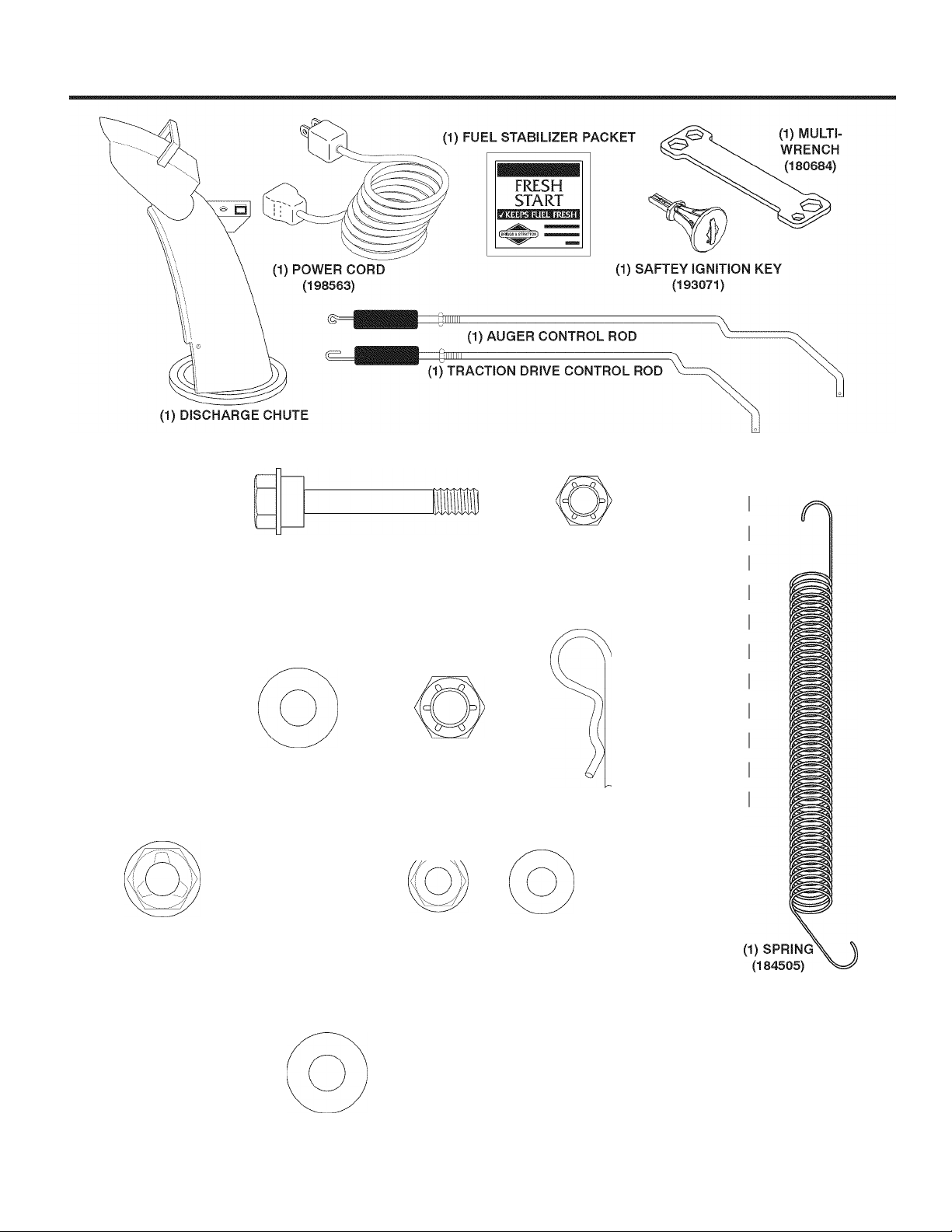
PARTS PACKED SEPARATELY IN CARTON
EXTRA SHEAR BOLTS AND NUTS
ROTATOR HEAD MOUNTING
(1) WASHER 3/8
(19131316)
(1) LOCKNUT (1) CARRIAGE BOLT
5/16-18 5/16-18x5/8
(751153) (72250505)
(2) SHOULDER
BOLT 1/4-20x1-3/4
(192090)
(1) LOCKNUT 3/8
(73800600)
CHUTE DEFLECTOR REMOTE CONTROL
(1) LOCKNUT (1) NYLON
1/4-20 WASHER
(191730) (179246)
(2) LOCKNUTS
1/4-20
(73800400)
(3) RETAINER
SPRINGS
(169675)
(1) SHOULDER
BOLT 1/4-20
(179829)
(2) FLAT WASHERS (2) CARRIAGE BOLTS
3/8-16x2.25
âr
(2) HANDLE KNOBS
Page 6
ASSEMBLY / PRE-OPERATION
Read these Instructions and this manual In Its entirety
before you attempt to assemble or operate your new
snow thrower. Reading the entire manual will familiar
ize you with the unit, which will assist you In assembly,
operation and maintenance of the product.
Your new snow thrower has been assembled at the factory
with the exception of those parts left unassembled for ship
ping purposes. All parts such as nuts, washers, bolts, etc,,
necessary to complete the assembly have been placed in
the parts bag. To ensure safe and proper operation of your
snow thrower, all parts and hardware you assemble must
be tightened securely. Use the correct tools as necessary
to ensure proper tightness,
REMOVE SNOW THROWER FROM CARTON
1, Remove all accessible loose parts and parts boxes
from carton,
2, Cut down all four corners of carton and lay panels flat,
3, Remove the two (2) screws securing the auger housing
to the pallet,
4, Remove all packing materials except plastictie holding
speed control rod to lower handle,
5, Remove the two (2) plastic ties securing upper handle
to pallet,
6, Remove snow thrower from carton and check carton
thoroughly for additional loose parts,
HOW TO SET UP YOUR SNOW THROWER
TOOL BOX (See Fig. 10)
A toolbox is provided on your snow thrower. The toolbox is
located on top of the belt cover. Store the extra shear bolts,
nuts and multi-wrench provided in parts bag in the toolbox,
NOTE: The multi-wrench may be used for assembly of the
chute rotator head to snow thrower and making adjustments
to the skid plates,
UNFOLD UPPER HANDLE
1, Raise upper handle to the operating position and
tighten handle knobs securely. Additional carriage
bolts, washers and handle knobs are in bag of parts.
Use to secure upper handle to lower handle. Install
in lower holes in handles,
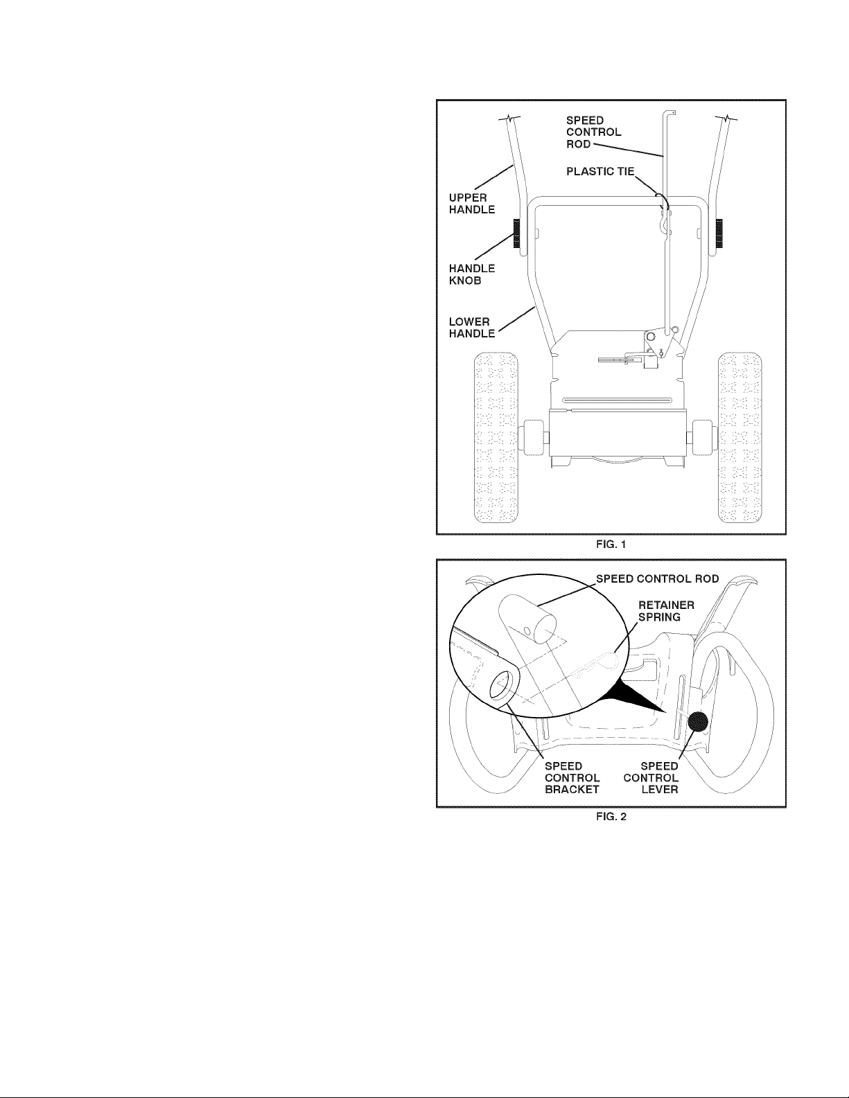
INSTALL SPEED CONTROL ROD (See Figs. 1 and 2)
1, Remove plastic tie securing rod to lower handle,
2, Insert rod into speed control bracket and secure with
retainer spring.
Page 7
ASSEMBLY / PRE-OPERATION
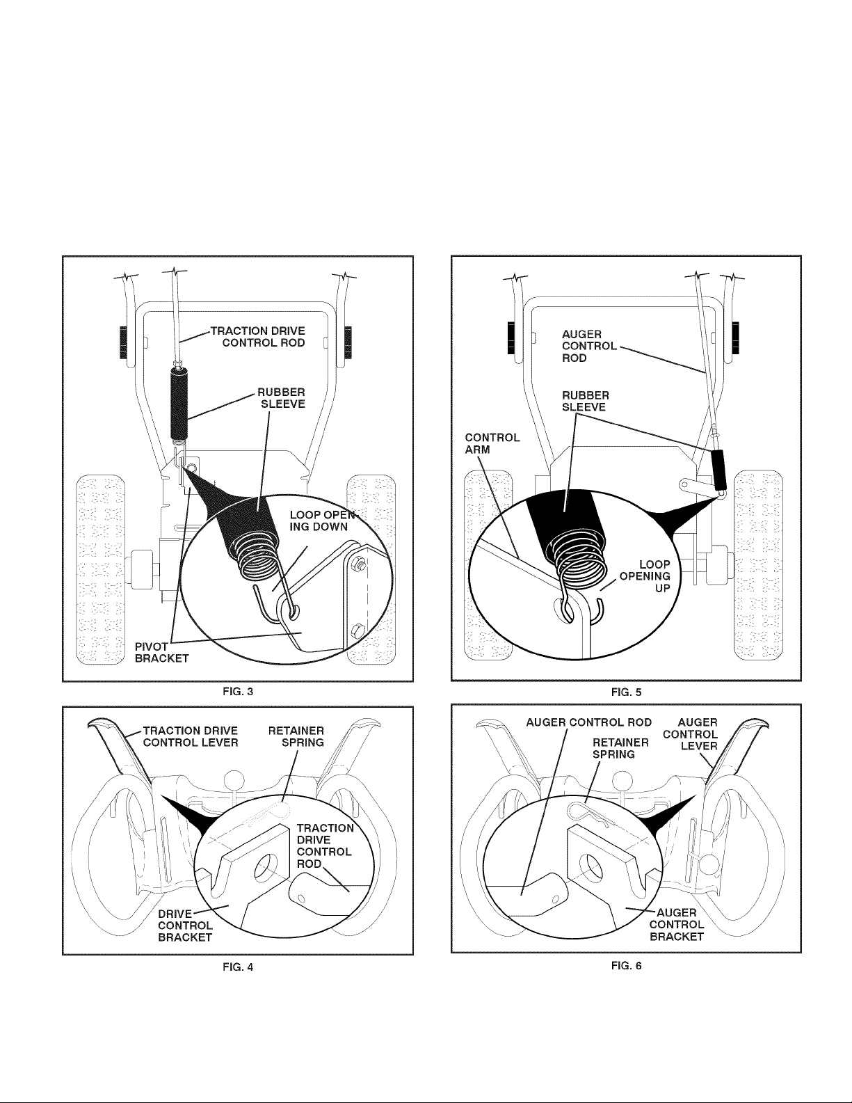
INSTALL TRACTION DRIVE CONTROL ROD
(See Figs. 3 and 4)
The traction drive controi rod has the iong ioop on the end
of the spring as shown,
1, Siide rubber sieeve up rod and hook end of spring into
pivot bracket with ioop opening down as shown,
2, With top end of rod positioned under ieft side of controi
panei, push rod down and insert top end of rod into hoie
in drive controi bracket. Secure with retainer spring.
INSTALL AUGER CONTROL ROD (See Figs. 5 and 6)
The auger controi rod has the short ioop on the end of the
spring as shown,
1, Siide rubber sieeve up rod and hook end of spring into
controi arm with ioop opening up as shown,
2, With top end of rod positioned under right side of
controi panei, push down on rod and insert end of rod
into hoie in auger controi bracket. Secure with retainer
spring.
Page 8
ASSEMBLY / PRE-OPERATION
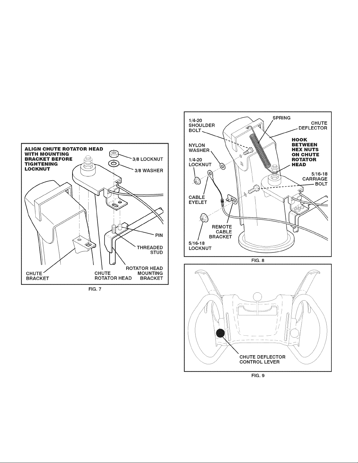
INSTALL DISCHARGE CHUTE / CHUTE ROTATOR
HEAD (See Fig. 7)
NOTE: The multi-wrench provided in your parts bag may
be used to install the chute rotator head,
1, Place discharge chute assembly on top of chute base
with discharge opening toward front of snow thrower,
2, Position chute rotator head over chute bracket. If neces
sary, rotate chute assemblyto align square and pin on un
derside of chute rotator head with holes in chute bracket,
3, With chute rotator head and chute bracket aligned,
position chute rotator head on pin and threaded stud
of mounting bracket,
4, Install 3/8 washer and locknut on threaded stud and
tighten securely.
INSTALL CHUTE DEFLECTOR REMOTE CONTROL
(See Figs. 8 and 9)
1, Install remote cable bracket to discharge chute with
5/16-18 carriage bolt and 5/16-18 locknut as shown.
Tighten securely,
2, Install remote cable eyelet to chute deflector with
1/4-20 shoulder bolt, nylon washer and 1/4-20 locknut
as shown. Tighten securely,
3, Install spring hooks between hex nuts on chute rotator
head and into hole in chute deflector as shown.
CHECK TIRE PRESSURE
The tires on your snow thrower were overinflated at the fac
tory for shipping purposes. Correct and equal tire pressure
is important for best snow throwing performance,
• Reduce tire pressure to 14-17 PSI (19-24,5 N-m),
Page 9
OPERATION
KNOW YOUR SNOW THROWER
READ THIS OWNER'S MANUALAND ALL SAFETY RULES BEFORE OPERATING YOUR SNOWTHROWER. Oompare
the illustrations with your snow thrower to famiiiarize yourseif with the iocation of various controis and adjustments. Save
this manuai for future reference.
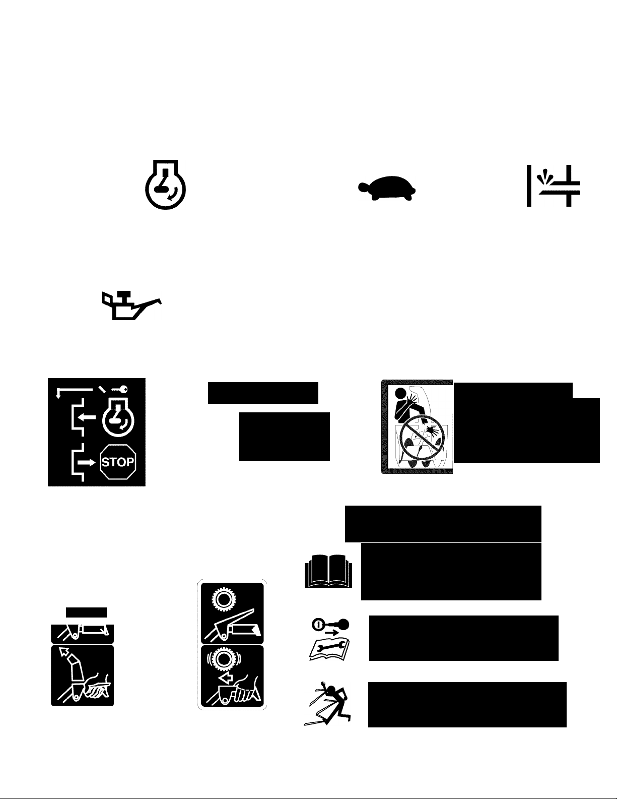
These symbols may appear on your snow thrower or In literature supplied with the product. Learn and understand
their meaning.
STOP
A
DANGER
OR WARNING
i
FUEL OIL
ENGINE
ON
ENGINE
OFF
F R
FORWARD REVERSE
4»
FAST SLOW
READ AND FOLLOW ALL SAFETY INFORMATION
AND INSTRUCTIONS BEFORE USE OF THIS PRODUCT.
KEEP THESE INSTRUCTIONS FOR FUTURE REFERENCE.
l\l
CHOKE PRIMER
IGNITION KEY.
INSERT TO START
AND RUN,
PULL OUT TO STOP.
DISENGAGED
ENGAGED
SNOW
DISCHARGE
A DANGER
TO AVOID INJURY FROM
ROTATING AUGER-KEEP
m
TRACTION
DRIVE CONTROL
HANDS, FEET AND
CLOTHING AWAY.
ADANGER
BLOCKAGES MUST NOT BE
CLEARED OUT UNTIL THE ENGINE
IS SHUT OFF, AND THE CLEAN
OUT TOOL MUST BE USED.
NEVER USE YOUR HAND TO
CLEAN OUT THE CHUTE.
A DANGER
• READ AND FDLLDW DWNER'S MANUAL.
• NEVER ALLOW CHILDREN TO OPERATE
SNOWTHROWERS.
• KEEP ALL SHIELDS AND GUARDS IN
PLACE WHILE OPERATING.
SHUT OFF ENGINE AND REMAIN BEHIND
HANDLES UNTIL ALL MOVING PARTS HAVE
STOPPED BEFORE UNCLOGGING OR
SERVICING UNIT.
TO AVOID THROWN OBJECT INJURIES
NEVER DIRECT DISCHARGE AT BYSTANDERS.
USE EXTRA CAUTION WHEN OPERATING ON
GRAVEL SURFACES.
Page 10
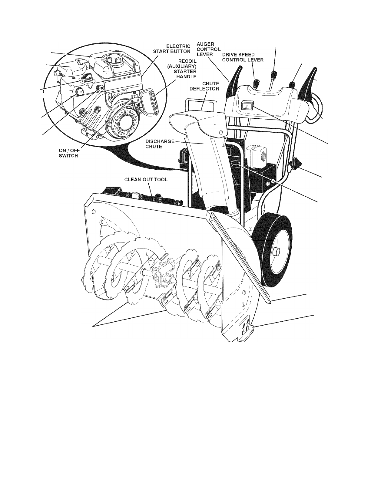
OPERATION
GASOLINE
FILLER CAP
MUFFLER
CHOKE
CONTROL
PRIMER
SAFETY
IGNITION
KEY
DISCHARGE CHUTE CONTROL LEVER
DEFLECTOR REMOTE
CONTROL LEVER
TRACTION
DRIVE
CONTROL
LEVER
LH TURN
TRIGGER
LIGHT
HANDLE
KNOB
TOOLBOX
NOTE: ITEMS ABOVE
ARE SHOWN IN
THEIR TYPICAL
LOCATION ON THE
ENGINE. ACTUAL
LOCATION MAY VARY
WITH THE ENGINE
ON YOUR UNIT.
AUGERS
FIG. 10
MEETS A.N.S.I. SAFETY REQUIREMENTS
Our snow throwers conform to the standards of the American National Standards Institute.
Toolbox - used to store spare shear bolts, locknuts and
wrench.
Safety Ignition key - must be inserted for the engine to
start and run. Remove when snow thrower is not in use.
Electric start button - used for starting the engine.
Recoil (auxiliary) starter handle-used for starting engine.
Primer - pumps additional fuel from the carburetor to the
cylinder for use when starting a cold engine.
Choke Control - used for starting a cold engine.
ON / OFF switch - used to STOP the engine.
LH and RH turn triggers - used to steer the snow thrower.
Drive speed control lever - used to select forward or
reverse motion and speed of snow thrower.
Traction drive control lever - used to engage power-pro
pelled forward or reverse motion of snow thrower.
Auger control lever - used to engage auger motion
(throw snow).
Discharge chute control lever - used to change the
direction the snow is thrown.
Deflector remote control lever - used to change the
distance the snow is thrown.
Skid plate-used to adjust height of scraper barfrom ground.
Drift cutter - used to cut through deep snowdrifts.
10
DRIFT CUTTER
SKID PLATE
Page 11
OPERATION
I The operation of any snow thrower can result
in foreign objects thrown into the eyes, which
can result in severe eye damage. Always wear
safety glasses or eye shields while operating
your snow thrower or performing any adjust
ments or repairs. We recommend standard safety glasses
or a wide vision safety mask worn over spectacles,
HOW TO USE YOUR SNOW THROWER
Know how to operate all controls before adding fuel or
attempting to start the engine,
STOPPING
TRACTION DRIVE
• Release traction drive control lever to stop the forward
or reverse movement of the snow thrower,
AUGER
• Release the auger control lever to stop throwing snow,
ENGINE
1, Move ON / OFF switch to “OFF” position,
2, Remove (do not turn) safety ignition key to prevent
unauthorized use,
NOTE: Never use choke to stop engine,
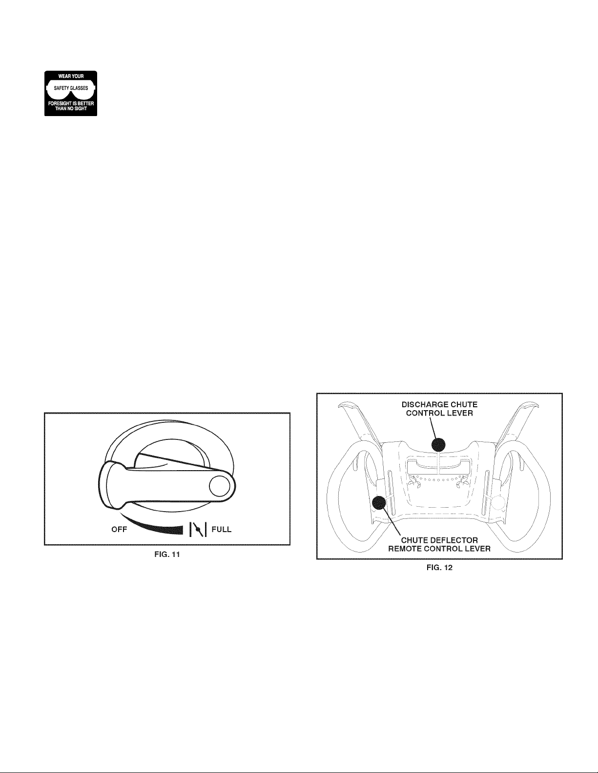
TO USE CHOKE CONTROL (See Fig. 11)
The choke control is located on the engine. Use the choke
control whenever you are starting a cold engine. Do not
use to start a warm engine,
• To engage choke, turn knob counterclockwise. Slowly
turn knob clockwise to disengage.
TO CONTROL SNOW DISCHARGE (See Fig. 12)
WARNING: Snow throwers have ex
posed rotating parts, which can cause
severe Injury from contact, or from ma
terial thrown from the discharge chute.
A
A
The DIRECTION in which snow is to be thrown is controiied
by the discharge chute controi iever,
• To change the discharge chute position, press downward
on discharge chute controi iever and move iever ieft
or right untii chute is in desired position. Be sure iever
springs back and iocks into desired position.
The DISTANCE that snow is thrown is controiied by the
position of the chute deflector. Set the defiector iow to
throw snow a short distance; set the defiector higher to
throw snow farther,
• Press downward on chute defiector controi iever and
move ieverforwardto iower the defiector and decrease
the distance. Move iever back to raise the defiector
and increase the distance. Be sure iever springs back
and iocks into desired position.
Keep the area of operation clear of all
persons, small children and pets at all
times Including startup.
WARNING: If the discharge chute or
auger become clogged, shut-off engine
and wait for all moving parts to stop. Use
the clean-out tool, NOT YOUR HANDS,
to unclog the chute and/or auger.
11
Page 12
OPERATION
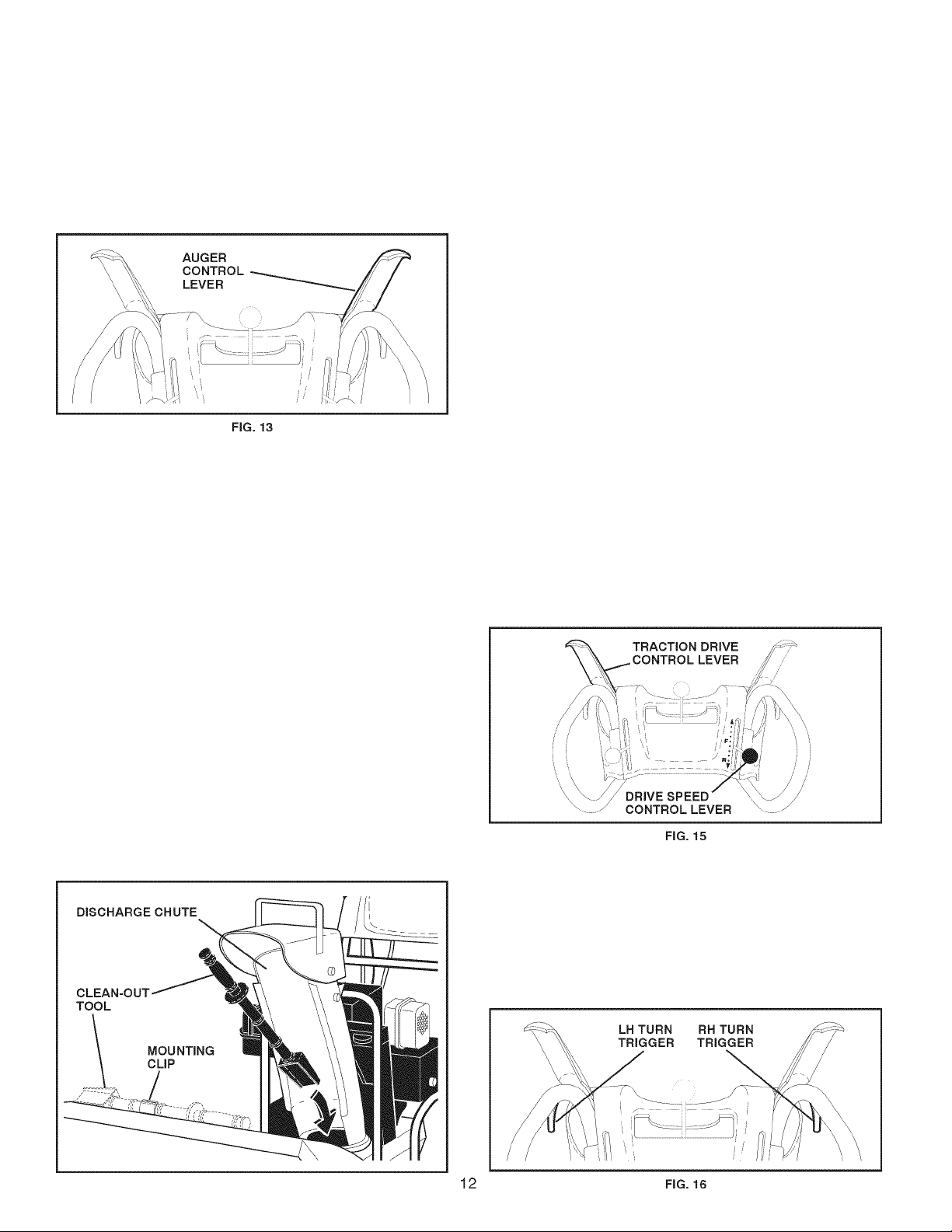
TO THROW SNOW (See Fig. 13)
The auger rotation is controiied by the auger controi iever
iocated on the right side handle,
• Squeeze auger control lever to handle to engage the
auger and throw snow,
• Release the auger control lever to stop throwing snow.
USING THE CLEAN-OUT TOOL (See Fig. 14)
In certain snow conditions, the discharge chute may be
come clogged with ice and snow. Use the clean-out tool
to dislodge this blockage.
When cleaning, repairing, or Inspecting, make
certain all controls are disengaged and the auger/lmpellerand all moving parts have stopped.
Disconnect the spark plug wire and keep the
wire away from the spark plug to prevent ac
cidental starting.
TO MOVE FORWARD AND BACKWARD (See Fig. 15)
SELF-PROPELLING, forward and reverse movement of
the snow thrower, is controlled by the traction drive control
lever located on the left side handle,
• Squeeze traction drive control lever to handle to engage
the drive system,
• Release traction drive control lever to stop the forward
or reverse movement of the snow thrower,
SPEED and DIRECTION are controlled by the drive speed
control lever,
• Press downward on the speed control lever and move
lever to desired position BEFORE engaging the trac
tion drive control lever. Be sure lever springs back and
locks into desired position.
CAUTION: Do not move speed control lever
when traction drive control lever Is engaged.
Damage to the snow thrower can result.
• Slower speeds are for heavier snow and faster speeds
are for light snow and transporting the snow thrower. It
is recommended that you use a slower speed until you
are familiar with the operation of the snow thrower,
NOTE: When both traction drive and auger control levers
are engaged, the traction drive control lever will lock the
auger control lever in the engaged position. This will allow
you to release your right hand from the handle and adjust
the discharge chute direction without interrupting the snow
throwing process.
• Release the auger control lever and shut off the engine,
• Remove the clean-out tool from it's mounting clip. Grasp
the tool firmly by the handle and push and twist the tool
into the discharge chute to dislodge the blockage.
After the packed snow has been dislodged, return the clean
out tool to it's mounting clip by pushing it into the clip,
• Make sure the discharge chute is pointed in a safe di
rection (no vehicles, buildings, people, or other objects
are in the direction of discharge) before restarting the
engine,
• Restart the engine, then squeeze the auger control
lever to the handle to clear snow from the auger hous
ing and the discharge chute.
POWER STEERING OPERATION (See Fig. 16)
Steering triggers are used to assist in steering your snow
thrower. The triggers are located on the underside of each
handle. When a trigger is squeezed, it disengages the drive
wheel on that side of snow thrower and allows it to turn in
that direction,
• To turn left - squeeze left side trigger,
• To turn right - squeeze right side trigger.
FIG. 14
Page 13
OPERATION
TO ADJUST SKID PLATES (See Fig. 17)
NOTE: The wrench provided in your parts bag may be
used to adjust the skid piates.
Skid piates are iocated on each side of the auger housing
and adjust the ciearance between the scraper bar and the
ground surface. Adjust skid piates eveniy to proper height
for current surface conditions. For removai of snow in
normai conditions, such as a paved driveway or sidewaik,
piace skid piates in the highest position (iowest scraper
ciearance) to give a 5 mm ciearance between the scraper
bar and the ground. Use a middle position if the surface
to be cleared is uneven,
NOTE: It is not recommended to operate the snow thrower
over gravel or rocky surfaces. Objects such as gravel, rocks
or other debris, can easily be picked up and thrown by the
impeller, which can cause serious personal injury, property
damage or damage to the snow thrower,
• If snow thrower must be operated over gravel surface,
use extra caution and be sure skid plates are adjusted
to lowest (highest scraper clearance) position,
1, Shut off engine and wait for all moving parts to stop,
2, Adjust skid plates by loosening the hex nuts, then mov
ing skid plate to desired position. Be sure both plates
are adjusted evenly. Tighten securely.
HIGH POSITION
(LOW GROUND
CLEARANCE)
AUGER
HOUSING
i j
----
7------------------------------------------------------------------------------
LOW POSITION (HIGH GROUND CLEARANCE)
■A
1 HEX
FIG. 17
V SCRAPER BAR
NUTS
SKID PLATE
SCRAPER BAR (See Fig. 17)
The scraper bar is not adjustable, but is reversible. After
considerable use it may become worn. When it has worn
almost to the edge of the housing, it can be reversed,
providing additional service before requiring replacement.
Replace a damaged or worn scraper bar,
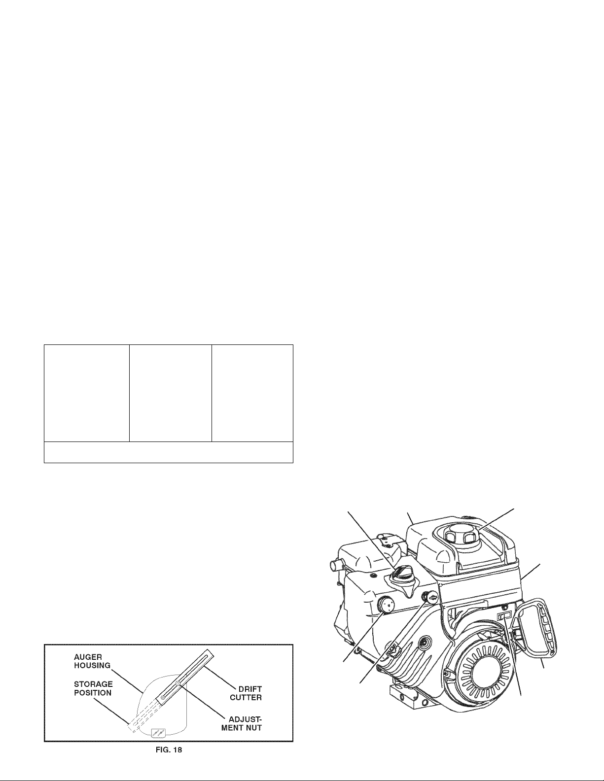
TO USE DRIFT CUTTERS (See Fig. 18)
Use the drift cutters to cut through deep snowdrifts that are
higher than the front of the snow thrower,
• Loosen upper adjustment nut enough to allow drift
cutter to be raised to highest position and tighten nut
securely. Repeat for opposite side of snow thrower,
• When not using drift cutters, loosen adjustment nut,
lower to storage position and tighten nut securely.
BEFORE STARTING THE ENGINE
CHECK ENGINE OIL LEVEL (See Fig. 19)
The engine on your snow thrower has been shipped, from
the factory, already filled with oil,
1, Check engine oil with snow thrower on level ground,
2, Remove oil fill cap/dipstick and wipe clean, reinsert
the dipstick and screw tight, wait for a few seconds,
remove and read oil level. If necessary, add oil until
“FULL mark on dipstick is reached. Do not overfill,
• To change engine oil, see “TO CHANGE ENGINE OIL
in the Maintenance section of this manual,
ADD GASOLINE (See Fig. 19)
• Fill fuel tank to bottom of tank filler neck. Do not over
fill, Use fresh, clean, regular unleaded gasoline with
a minimum of 87 octane. Do not mix oil with gasoline.
Purchase fuel in quantities that can be used within 30
days to assure fuel freshness.
WARNING: Wipe off any spilled oil or
A
CAUTION: Alcohol blended fuels (called gasohol or using ethanol or methanol) can attract
moisture which leads to separation and for
mation of acids during storage. Acidic gas can
damage the fuel system of an engine while In
storage. To avoid engine problems, the fuel
system should be emptied before storage of
30 days or longer. Empty the gas tank, start
the engine and let It run until the fuel lines and
carburetor are empty. Use fresh fuel next sea
son. See Storage Instructions for additional
Information. Never use engine or carburetor
cleaner products In the fuel tank or permanent
damage may occur.
CHOKE
CONTROL
fuel. Do not store, spill or use gasoline
near an open flame.
ENGINE OIL
FILL CAP/DIPSTICK
GASOLINE
FILLER CAP
STARTER
BUTTON
PRIMER
SAFETY
IGNITION
KEY
NOTE: ALL ITEMS ARE SHOWN IN THEIR TYPICAL LOCATION.
ACTUAL LOCATION MAY VARY WITH ENGINE ON YOUR UNIT.
13
FIG. 19
ON/OFF
SWITCH
RECOIL
STARTER
HANDLE
Page 14

OPERATION
TO START ENGINE
Your snow thrower engine is equipped with both a 120 Voit
A.C, eiectric starter and a recoii starter. The eiectric starter
is equipped with a three-wire power cord and piug and is
designed to operate on 120 Voit A.C, househoid current,
• Be sure your house is a 120 Voit A.C, three-wire
grounded system. If you are uncertain, consuit a
iicensed eiectrician.
WARNING: Do not use the electric
starter If your house Is not a 120 Volt
A.C. three-wire grounded system. Se
A
COLD START - ELECTRIC STARTER
1, Insert safety ignition key (packed separateiy in parts
bag) into ignition siotuntii it ciicks, DO NOT turn the key.
Keep the extra safety ignition key in a safe piace,
2, Piace ON / OFF switch in “ON” position,
3, Rotate choke controi to “FULL position,
4, Connect the power cord to the engine,
5, Piug the other end of the power cord into a three-hoie
grounded 120 Voit A.C, receptacie,
NOTE: Do not use primer when starting engine with the
eiectric starter,
6, Push starter button untii engine starts,
IMPORTANT; Do not crank engine more than five con
tinuous seconds between each time you try to start. Wait
5 to 10 seconds between each attempt,
7, When the engine starts, reiease the starter button and
siowiy move the choke controi to the “OFF” position,
8, Disconnect the power cord from the receptacie first,
then from the engine,
Aiiow the engine to warm up for a few minutes. Engine wiii
not deveiop fuii power untii it has reached normai operat
ing temperature,
WARM START - ELECTRIC STARTER
Follow the steps above, keeping the choke controi in the
“OFF” position,
COLD START - RECOIL STARTER
1, Insert safety ignition key (packed separateiy in parts
bag) into ignition siotuntii it ciicks, DO NOT turn the key.
Keep the extra safety ignition key in a safe piace,
2, Piace ON / OFF switch in “ON” position,
3, Rotate choke controi to “FULL position,
4, Push the primer four (4) times if the temperature is
beiow 15°F or two (2) times if temperature is between
15° and 50°F, If temperature is above 50°F, priming is
not necessary,
NOTE: Over priming may cause flooding, preventing the
engine from starting. If you do flood the engine, wait a few
minutes before attempting to start and DO NOT push the
primer.
rious personal Injury or damage to your
snow thrower could result.
5, Puii recoil starter handle quickly. Do not allow starter
rope to snap back,
6, When the enginestarts, release the recoil starter handle
and slowly move the choke control to the “OFF” posi
tion,
Aiiow the engine to warm up for a few minutes. Engine wiii
not deveiop fuii power untii it has reached normai operat
ing temperature,
WARM START - RECOIL STARTER
Follow the steps above, keeping the choke in the “OFF”
position, DO NOT push the primer,
BEFORE STOPPING
Run the engine for a few minutes to heip dry off any mois
ture on the engine,
IF RECOIL STARTER HAS FROZEN
If the recoil starter has frozen and will not turn the engine,
proceed as foiiows:
1, Grasp the recoii starter handle and slowly pull as much
rope out of the starter as possible,
2, Release the recoil starter handle and let it snap back
against the starter.
If the engine stiii faiis to start, repeat the above steps or
use the eiectric starter,
SNOW THROWING TIPS
• Go siower in deep, freezing or heavy wet snow. Use
the drive speed control, NOT the ON / OFF switch, to
adjust speed,
• It is easier and more efficient to remove snow immediateiy after it faiis.
The best time to remove snow is the eariy morning. At
this time the snow is usuaiiy dry and has not been ex
posed to the direct sun and warming temperatures,
Siightiy overiap each successive path to ensure aii
snow wiii be removed.
Throw snow downwind whenever possibie.
Adjust the skid piates to proper height for current snow
conditions. See “TO ADJUST SKID PLATES” in this
section of this manuai.
For extremeiy heavy snow, reduce the width of snow
removai by overiapping previous path and moving
siowiy.
Keep engine ciean and dear of snow during use. This
wiii heip air flow and extend engine iife.
After snow-throwing is compieted, aiiow engine to run for
a few minutes to meit snow and ice off the engine,
Ciean the entire snow thrower thoroughiy after each
use and wipe dry so it is ready for next use.
WARNING: Do not operate snow
thrower Ifweather conditions impairvis-
A
Ibility. Throwing snow during a heavy,
windy snowstorm can blind you and be
hazardous to the safe operation of the
snow thrower.
14
Page 15
MAINTENANCE
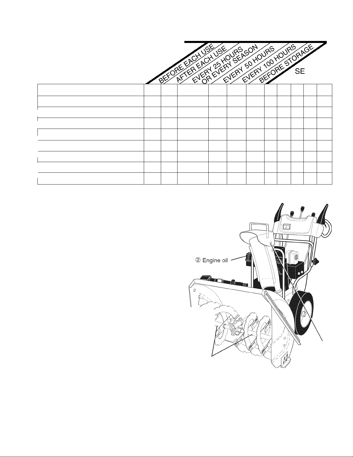
MAINTENANCE SCHEDULE
FILL IN DATES
AS YOU COMPLETE
REGULAR SERVICE
T
Check for Loose Fasteners
H
R
Clean / Inspect Snow Thrower
O
Check / Replace V-Belts
W
E
Lubrication Chart
R
✓
✓ ✓
✓
✓
RVICE
DATES
✓
✓
Check Engine Oil Level
E
Change Engine Oil
N
G
Inspect Muffler
I
N
Check / Replace Spark Plug
E
Empty Fuel Tank
✓
GENERAL RECOMMENDATIONS
The warranty on this snow thrower does not cover items
that have been subjected to operator abuse or negligence.
To receive full value from the warranty, operator must
maintain snow thrower as instructed in this manual. Some
adjustments will need to be made periodically to properly
maintain your snow thrower.
At least once a season, check to see if you should make
any of the adjustments described in the Service and Ad
justments section of this manual,
• At least once a year, you should replace the spark plug
and check belts for wear, A new spark plug will help
your engine run better and last longer,
• Follow the maintenance schedule in this manual,
NOTE: Use only Original Equipment Manufacturer (OEM)
parts to service this unit. Failure to do so can cause the unit
to malfunction and pose a risk of injury to the operator.
✓
✓
✓
✓
LUBRICATION CHART
© SAE 5W-30 Motor Oil
® See “ENGINE” In
Maintenance section
General
Purpose
Grease
BEFORE EACH USE
1, Check engine oil level.
2, Check for loose fasteners.
3, Check controls to be sure they are functioning properly.
LUBRICATION
Keep your snow thrower well lubricated
(See “LUBRIOATION OH ART”),
SNOW THROWER
Always observe the safety rules when performing any
maintenance,
TIRES
• Maintain proper air pressure in both tires (14-17 P,S,I,
/19-24,5 N-m),
1 ' ©
1 f ; r
© Pivot
points
@ Auger
grease fittings
• Keep tires free of gasoline and oil, which can harm
rubber,
NOTE: To seal tire punctures and prevent flat tires due
to slow leaks, tire sealant may be purchased from your
local parts dealer. Tire sealant also prevents tire dry rot
and corrosion.
15
Page 16
MAINTENANCE
V-BELTS
Check V-belts for deterioration and wear after every 50
hours of operation and repiace if necessary. The beits
are not adjustabie, Repiace beits if they begin to siip from
wear. (See “TO REMOVE BELT COVER” in the Service
and Adjustments section of this manuai).
The V-beits on your snow thrower are of speciai construction
and shouid be repiaced by originai equipment manufacturer
(OEM) beits avaiiabiefrom your nearest deaier. Using other
than OEM beits can cause personai injury or damage to
the snow thrower,
AUGER GEAR CASE
• The gear case was fiiied with iubricant to the proper
ievei at the factory. The oniy time the iubricant needs
attention is if service has been performed on the gear
case,
• If iubricant is required, use oniy Ronex ED #1 grease,
TRACTION DRIVE SYSTEM
DO NOT lubricate the drive components inside the snow
thrower. The sprockets, hex shafts, drive disc and friction
wheel require no lubrication. The bearings and bushings
are lifetime lubricated and require no maintenance.
CAUTION: Any lubricating of the above compo
nents can cause contamination of the friction
wheel and damage to the drive system of your
snow thrower.
ENGINE
LUBRICATION
Use only high quality detergent oil rated with API service
classification SG-SL, Select the oil's SAE viscosity grade
according to your expected operating temperature.
SAE VISCOSITY GRADES
5W30 or 10W30
Synthetic 5W30or10W30
-20 30
1
-30
TEMPERATURE RANGE ANTICIPATED
NOTE: Although multi-viscosity oils (5W30, 10W30 etc.)
improve starting in cold weather, these multi-viscosity oils
will result in increased oil consumption when used above
32°F/0°C, Check your engine oil level more frequently to
avoid possible engine damage from running low on oil.
Change the oil after every 25 hours of operation or at least
once a year if the snow thrower is not used for 25 hours
in one year.
Check the crankcase oil level beforestartingthe engine and
after each five (5) hours of continuous use. Tighten oil fill
cap / dipstick securely each time you check the oil level.
-20
BEFORE NEXT OIL CHANGE
-10
1
32 40
0 10
TO CHANGE ENGINE OIL
Determine temperature range anticipated before next oil
change. All oil must meetAPI service classification SG-SL,
• Be sure snow thrower is on level surface,
• Oil will drain more freely when warm,
• Catch oil in a suitable container,
NOTE: The left side wheel may be removed from snow
thrower for easier access to the oil drain plug and place
ment of a suitable container. The unit tilted, resting on the
frame with the left wheel removed, will help drain any oil
trapped inside the engine, (See “TO REMOVE WHEELS”
in the Service and Adjustments section of this manual),
1, Remove safety ignition key and disconnect spark plug
wire from spark plug. Place wire where it cannot come
in contact with plug.
2, Clean area around drain plug,
3, Remove drain plug and drain oil in a suitable container,
4, Install drain plug and tighten securely,
5, Wipe off any spilled oil from snow thrower and engine,
6, Install left wheel (if removed for draining oil). Be sure to
install klick pin into proper hole in wheel axle (See “TO
REMOVE WHEELS” in the Service and Adjustments
section of this manual),
7, Remove oil fill cap/dipstick. Be careful not to allow dirt
to enter the engine,
8, Refill engine with oil through oil dipstick tube. Pour
slowly. Do not overfill. For approximate capacity see
“PRODUCT SPECIFICATIONS” section ofthis manual,
9, Use gauge on oil fill cap/dipstick for checking level.
Be sure dipstick cap is tightened securely for accurate
reading. Keep oil at “FULL line on dipstick,
10, Wipe off any spilled oil,
MUFFLER
Inspect and replace corroded muffler as it could create a
fire hazard and/or damage,
SPARK PLUG
Replace spark plug at the beginning of each season or after
every 100 hours of operation, whichever occurs first. Spark
plug type and gap setting are shown in the “PRODUCT
SPECIFICATIONS” section of this manual,
CLEANING
IMPORTANT: For best performance, keep snow thrower
housing free of any dirt or trash. Clean the outside of your
snow thrower after each use.
WARNING: Remove safety Ignition key
and disconnect spark plug wire from
A
Keep finished surfaces/wheels free ofgasoline, oil, etc.
We do not recommend using a garden hose to clean
your snow thrower unless the electrical system, muffler
and carburetor are covered to keep water out. Water
in engine can result in shortened engine life.
spark plug. Place wire where It cannot
come In contact with plug.
16
Page 17
SERVICE AND ADJUSTMENTS
WARNING: To avoid serious Injury, before
performing any service or adjustments:
1. Be sure the on/off switch Is In the
OFF position.
2. Remove safety Ignition key.
A
3. Make sure the augers and all moving
parts have completely stopped.
4. Disconnect spark plug wire from
spark plug and place wire where It
cannot come In contact with plug.
SNOW THROWER
TO ADJUST SNOW THROWER HEIGHT
See “TO ADJUST SKID PLATES” and “SCRAPER BAR”
in the Operation section of this manuai,
CHUTE DEFLECTOR
The chute defiector, attached to the top of the discharge
chute, is provided to direct discharging snow away from
the operator. If the deflector becomes damaged, it shouid
be repiaced.
WARNING: To avoid serious Injury,
never operate your snow thrower with
A
the deflector removed or damaged.
1, Disengage aii controis and move throttie controi to
STOP position. Wait for aii moving parts to stop,
2, Remove safety ignition key and disconnect spark piug
wire from spark piug, Piace wire where it cannot come
in contact with piug,
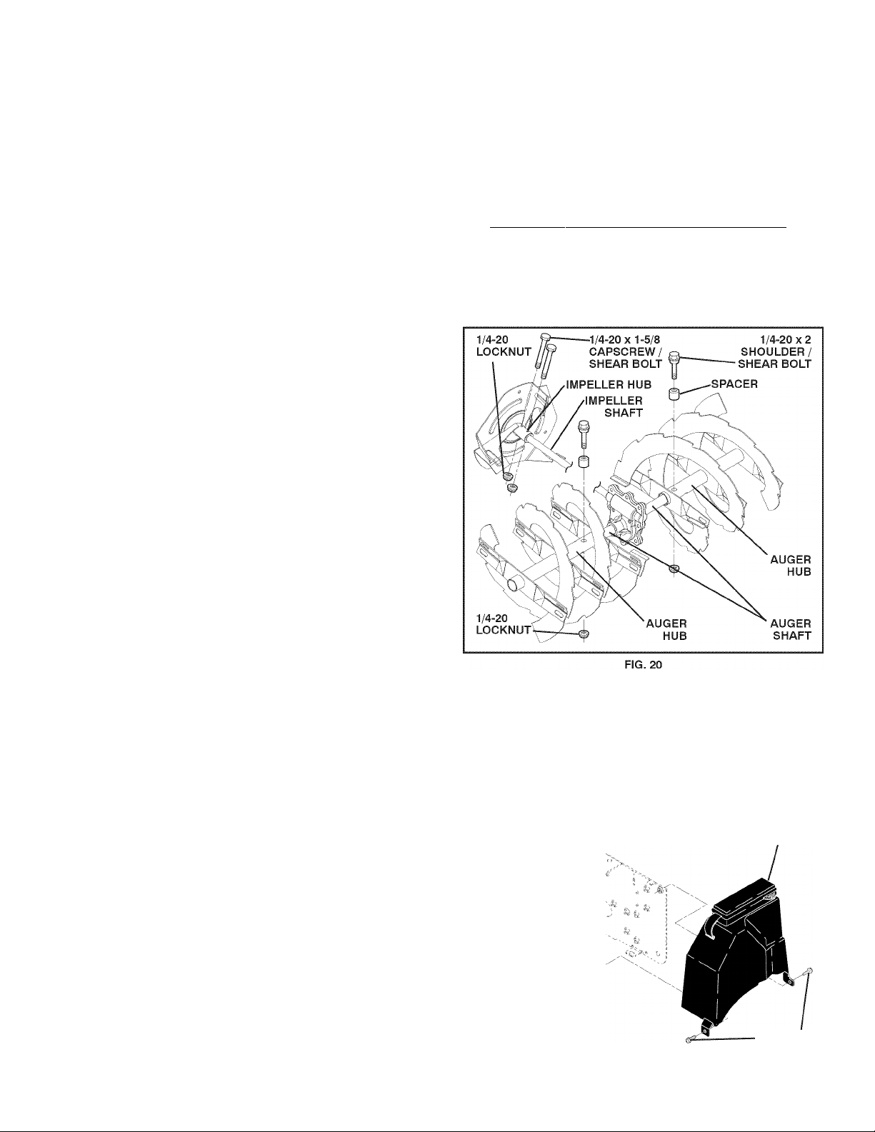
3, Aiign hoies in impeiier hub with hoies in impeiier shaft
and instaii two (2) new 1/4-20 x 1-5/8" capscrew/shear
boits, Instaii 1/4-20 iocknuts and tighten secureiy,
CAUTION: Do not substitute. Use only original
equipment capscrew/shear bolts as supplied
with your snow thrower.
Connect spark piug wire to spark piug, Repiace safety
ignition key.
• To change direction and/or distance snow is discharged,
see “TO CONTROL SNOW DISCHARGE” in the Op
eration section of this manuai,
SHEAR BOLTS (See Fig. 20)
AUGER SHEAR BOLTS
Both right and ieft-hand augers are secured to the auger
shaft with a shouider/shear boit and hex nut, Shouid a for
eign object or ice become iodged in the augers, the shear
boits are designed to break, preventing damage to any
other components. If one or both augers do not turn when
auger control lever is engaged, check to see if one or both
of the boits have sheared. To repiace the shear boits:
1, Disengage aii controis and move throttie controi to
STOP position or move ON/OFF switch to OFF posi
tion, Wait for aii moving parts to stop,
2, Remove safety ignition key and disconnect spark piug
wire from spark piug, Piace wire where it cannot come
in contact with piug,
3, Aiign hoie in auger hub with hoie in auger shaft and
instaii a new 1/4-20 x 2" shouider/shear boit, Instaii
1/4-20 iock nut and tighten secureiy,
CAUTION: Do not substitute. Use only original
equipment shear bolts as supplied with your
snow thrower.
4, Connect spark piug wire to spark piug, Repiace safety
ignition key,
IMPELLER SHEAR BOLTS
The impeller is secured to the impeiier shaft with two (2)
capscrew/shear boits and hex nuts, Shouid a foreign object
or ice become iodged in the impeiier, the capscrews are
designed to break, preventing damage to any other com
ponents, If impeller does not turn when auger control lever
is engaged, check to see if the capscrews have sheared.
To repiace the capscrew/shear boits:
TO REMOVE BELT COVER (See Fig. 21)
1, Remove the two (2) screws securing beit cover to
frame,
2, Remove beit cover,
• Repiace beit cover by instaiiing cover and screws and
tighten secureiy.
BELT
COVER
'A
r\Qs .
FRAME SCREWS
FIG. 21
17
Page 18
SERVICE AND ADJUSTMENTS
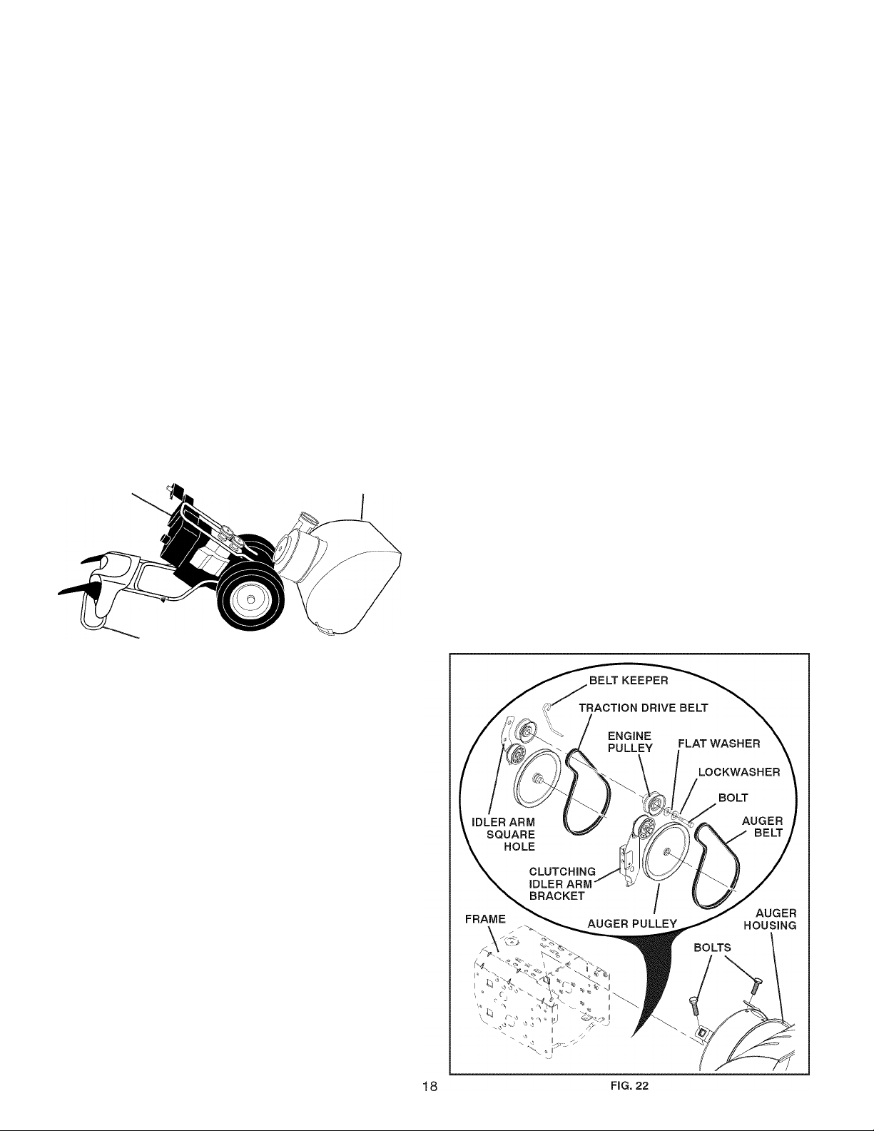
TO REPLACE BELTS (See Fig. 22)
The auger and traction drive beits are not adjustabie. If the
beits are damaged or begin to siip from wear, they shouid
be repiaced. It is recommended that the beit(s) be repiaced
by a Sears service centre/department,
NOTE: It is recommended that both the auger and traction
drive beit be repiaced at the same time.
The V-beits on your snow thrower are of speciai construction
and shouid be repiaced by originai equipment manufacturer
(OEM) beits avaiiabie from your nearest Sears service
centre/department. Using other than OEM beits can cause
personai injury or damage to the snow thrower.
WARNING: Belt replacement requires
separation of the snow thrower. While
separating the auger housing from the
frame assembly, It Is important that
an assistant stand In the operating
A
FRAME
ASSEMBLY
position and hold the snow thrower
handles. Serious personal injury and/or
damage to the unit could occur if the
snowthrower should fall during the belt
changing process.
AUGER
HOUSING
HANDLES
8, RELIEVE TENSION ON TRAOTION DRIVE BELT
IDLER and remove traction drive beit from around
puiieys,
HINT: Insert a 3/8" drive ratchet (in the “ON” position) into
the square hoie in idler arm and rotate ratchet clockwise
to reiieve tension,
9, With tension reiieved on idler, install new traction drive
beit around puiieys and inside beit keepers,
10, Instaii ciutch rod in swing piate; secure with hairpin,
11, Piace auger beit around and inside the groove of auger
puiiey oniy,
12, Whiie your assistant siowiy raises handles to rejoin
the auger housing and frame assembiy, puii up on the
auger beit and squeeze sides together above puiiey
so beit is fuiiy seated in groove of puiiey,
13, Move idler arm so it does not hit impeiier puiiey as you
bring snow thrower compieteiy together and check
carefuiiy for proper routing of beits. If auger belt has
become dislodged from the pulley (by catching the idier
arm bracket whiie bringing snow thrower together),
separate the snow thrower and repeat step 12, Beit
must be fuiiy seated in puiiey groove when bringing
the snow thrower together,
14, Instaii the two (2) hex boits and tighten secureiy,
15, INSTALL ENGINE PULLEY - Place beltinpulley groove
and slide puiiey on crankshaft, Instaii fiat washer,
iockwasher and boit and tighten secureiy (41 -47 N-m
torque). Make sure beit is inside beit keeper,
16, INSTALL BELT COVER and two (2) screws. Tighten
secureiy,
17, INSTALL DISCHARGE CHUTE - See “INSTALL DIS
CHARGE CHUTE / CHUTE ROTATER HEAD” in the
Assembiy / Pre-Operation section of this manuai.
1, REMOVE GASOLINE FROM FUEL TANK - Drain
gasoiine from fuei tank into a suitabie container, out
doors, away from fire or fiame. Wipe up any spiiied
gasoiine,
2, REMOVE DISOHARGE GHUTE - Loosen iocknut
securing chute rotator head to mounting bracket oniy
enough to aiiow chute rotator head to be raised and
discharge chute to be removed from snow thrower,
3, REMOVE BELT OOVER - See “TO REMOVE BELT
OOVER” in this section of this manuai,
4, REMOVE ENGINE PULLEY-Remove bolt, lockwasher
and flat washer securing puiiey to engine crankshaft.
Remove outside (auger) puiiey oniy from crankshaft,
5, SEPARATE SNOW THROWER - With your assistant
standing in the operating position hoiding the handles,
remove the two (2) bolts holding the auger housing and
frame together.
WARNING: As the last bolt Is removed,
A
6. REMOVE HAIRPIN FROM OLUTOH ROD and remove
clutch rod from swing piate. Tip swing pi ate forward,
7, REMOVE AUGER BELT from around puiiey.
have your assistant carefully lower the
handles down to the ground.
Page 19
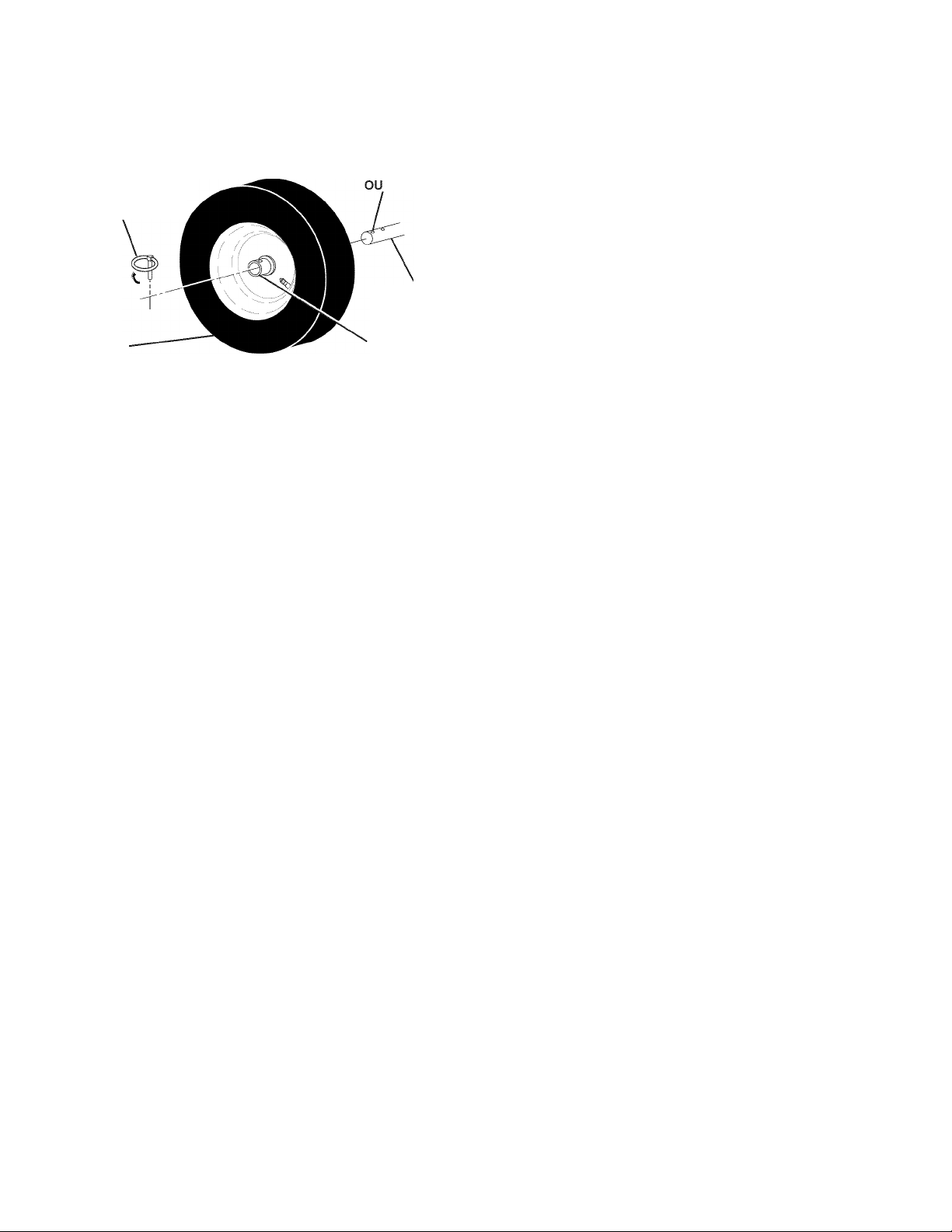
TO REMOVE WHEELS (See Fig. 23)
• Remove the klik pin and remove wheel from axle,
IMPORTANT: When installing wheel, be sure to use the
axle hole closest to the end of the shaft - do not use the
hole in the wheel hub (if equipped). Inner hole in axle and
hole in wheel hub are not usedforyourmodel snow thrower.
KLIK PIN (INSTALL
IN OUTER HOLE
OF AXLE ONLY)
WHEEL
FIG. 23
HOLE
AXLE
WHEEL HUB
STORAGE
NOTE: To seal punctures or prevent flat tires due to slow
leaks, tire sealant may be purchased from your local parts
dealer. Tire sealant also prevents tire dry rot and corrosion,
ENGINE
CARBURETOR
Your carburetor is not adjustable. Engine performance
should not be affected at altitudes up to 7,000 feet (2,134
meters). If your engine does not operate properly due to
suspected carburetor problems, take your snow thrower
to a Sears service centre/department,
ENGINE SPEED
Never tamper with the engine governor, which is factory set
for proper engine speed. Overspeeding the engine above
the factory high speed setting can be dangerous and will
void the warranty. If you think the engine-governed high
speed needs adjusting, contact a Sears Parts & Repair
Center, which has the proper equipment and experience
to make any necessary adjustments.
Immediately prepare your snow thrower for storage at
the end of the season or if the unit will not be used for 30
days or more.
WARNING: Never store the snow
thrower with gasoline In the tank Inside
a building where fumes may reach an
open flame, spark or pilot light as on a
A
furnace, water heater, clothes dryer or
gas appliance. Allowthe engineto cool
before storing In any enclosure.
SNOW THROWER
When snow thrower is to be stored for a period of time,
clean it thoroughly, remove all dirt, grease, leaves, etc.
Store in a clean, dry area,
1, Clean entire snow thrower (See “CLEANING” in the
Maintenance section of this manual),
2, Inspect and replace belts, if necessary (See “TC RE
PLACE BELTS” in the Service and Adjustments section
of this manual),
3, Lubricate as shown in the Maintenance section of this
manual,
4, Be sure thatall nuts, bolts, screws, and pins are securely
fastened. Inspect moving parts for damage, breakage
and wear. Replace if necessary,
5, Touch up all rusted or chipped paint surfaces; sand
lightly before painting,
ENGINE
FUEL SYSTEM
IMPORTANT: It is important to prevent gum deposits from
forming in essential fuel system parts such as carburetor,
fuel hose, or tank during storage. Alcohol blended fuels
(called gasohol or using ethanol or methanol) can attract
moisture which leads to separation and formation of acids
during storage. Acidic gas can damage the fuel system of
an engine while in storage.
• Empty the fuel tank by starting the engine and letting
it run until the fuel lines and carburetor are empty,
• Never use engine or carburetor cleaner products in
the fuel tank or permanent damage may occur,
• Use fresh fuel next season,
NOTE: Fuel stabilizer is an acceptable alternative in min
imizing the formation of fuel gum deposits during storage.
Add stabilizer to gasoline in fuel tank or storage container.
Always follow the mix ratio found on stabilizer container.
Run engine at least 10 minutes after adding stabilizer to
allow the stabilizer to reach the carburetor. Do not empty
the gas tank and carburetor if using fuel stabilizer,
ENGINE OIL
Drain oil (with engine warm) and replace with clean engine
oil, (See “ENGINE” in the Maintenance section of this
manual),
CYLINDER
1, Remove spark plug,
2, Pour approximately one ounce (30 ml) of oil through
spark plug hole into cylinder,
3, Pull recoil starter handleslowly a few times to distribute
oil,
4, Replace with new spark plug,
OTHER
• Remove safety ignition key; store it in a safe place,
• Do not store gasoline from one season to another,
• Replace your gasoline can if your can starts to rust.
Rust and/or dirt in your gasoline will cause problems,
• If possible, store your snow thrower indoors and cover
it to protect it from dust and dirt,
• Cover your snow thrower with a suitable protective
cover that does not retain moisture. Do not use plastic.
Plastic cannot breathe, which allows condensation to
form and will cause your snow thrower to rust,
IMPORTANT: Never cover snow thrower while engine/ex-
haust area is still warm.
19
Page 20

TROUBLESHOOTING
See appropriate section in manuai unless directed to a Sears service centre/department.
PROBLEM CAUSE CORRECTION
Does not start 1. Fuel shut-off valve (If so
equipped) In OFF position.
2. Safety Ignition key
Is not inserted.
3. Out of fuel. 3. Fill fuel tank with fresh, clean gasoline.
4. Throttle in STOP position
(or ON/OFF switch is OFF).
5. Ohoke in OFF position. 5. Move to FULL position.
6. Primer not depressed. 6. Prime as instructed in the Operation section of this manual.
7. Engine is flooded. 7. Wait a few minutes before restarting, DO NOT prime.
8. Spark plug wire is
disconnected.
9. Bad spark plug. 9. Replace spark plug.
10. Stale fuel. 10. Empty fuel tank & carburetor, refill with fresh, clean gasoline.
11. Water in fuel. 11. Empty fuel tank & carburetor, refill with fresh, clean gasoline.
Loss of power 1. Spark plug wire loose. 1. Reconnect spark plug wire.
2. Throwing too much snow. 2. Reduce speed and width of swath.
3. Fuel tank cap is covered
with ice or snow.
4. Dirty or clogged muffler. 4. Olean or replace muffler.
1. Turn fuel shut-off valve to OPEN position.
2. Insert safety ignition key.
4. Move throttle to FAST position
(or ON/OFF switch to ON position).
8. Oonnect wire to spark plug.
3. Remove ice and snow on and around fuel tank cap.
Engine idies or 1. Ohoke is in FULL position. 1. Move choke to OFF position.
runs roughiy 2. Blockage in fuel line. 2. Olean fuel line.
3. Stale fuel. 3. Empty fuel tank & carburetor, refill with fresh, clean gasoline.
4. Water in fuel. 4. Empty fuel tank & carburetor, refill with fresh, clean gasoline.
5. Oarburetor is in need of
adjustment or overhaul.
Excessive
vibration
Recoii starter
is hard to pull
Loss of traction 1. Drive belt is worn. 1. Oheck / replace drive belt.
drive / siowing 2. Drive belt is off of pulley. 2. Oheck / reinstall drive belt.
of drive speed 3. Friction drive wheel is worn. 3. Oontact a Sears service centre/department.
Loss of snow 1. Auger belt is off of pulley. 1. Oheck / reinstall auger belt.
discharge or 2. Auger belt is worn. 2. Oheck / replace auger belt.
siowing of 3. Ologged discharge chute. 3. Olean snow chute.
snow discharge 4. Augers / impeller jammed. 4. Remove debris or foreign object from augers / impeller.
1. Loose parts or damaged
augers or impeller.
1. Frozen recoil starter. 1. See “IF REOOIL STARTER HAS FROZEN”
5. Oontact a Sears service centre/department.
1. Tighten all fasteners. Replace damaged parts. If vibration
remains, contact a Sears service centre/department.
in the Operation section of this manual.
20
Page 21
IMPORTANTE
Procedimientos de Funcionamiento Seguro Para Máquinas Quitanieves
Esta máquina puede amputar manos y pies y ianzar objetos,
Ei no observar i as siguientes instrucciones de seguridad puede dar iugar a heridas graves.
A
A
A
A
A
Busque este símbolo que se
ñala las precauciones de segu
ridad de importancia. Quiere decir
¡ATENCIÓN! ¡ESTE ALERTO! SU
SEGURIDAD ESTA COMPROMETIDA.
ADVERTENCIA: Siempre desconecte el
alambre déla bujía y póngalo donde no
pueda entrar en contacto con la bujía,
para evitar el arranque por accidente,
durante la preparación, el transporte, el
ajuste o cuando se hacen reparaciones.
ADVERTENCIA: Esta máquina quita
nieves se puede utilizar en aceras,
vías de acceso y otras áreas a nivel
del suelo. Hay que tener precaución
usándola sobre pendientes. No usar la
máquina quitanieves en áreas sobre el
nivel del suelo, como techos de casas,
garajes, pórticos u otras estructuras o
edificios similares.
ADVERTENCIA: Las máquinas quita
nieves tienen partes giratorias expues
tas, que pueden causar heridas graves
por contacto, o por material lanzado
desde el conducto de eyección. Man
tener siempre el área de operación li
bre de toda persona, niños pequeños y
animales domésticos. Incluso durante
la puesta en marcha.
PRECAUCIÓN: El silenciador y otras
piezas del motor llegan a sre extrema
damente callentes durante la operación
y siguen siendo callentes después de
que el motor haya parado. Para evitar
quemadurasseveras, permanezca lejos
de estas áreas.
ADVERTENCIA: El tubo de escape del
motor, algunos de sus constituyentes y
algunos componentes del vehículo con
tienen o desprenden productos quími
cos conocidos en el Estado de Califor
nia como causa de cáncer y defectos al
nacimiento u otrosdaños reproductivos.
Formación
1, Antes de hacerfuncionar esta unidad hay que leer, com
prender y seguir todas las instrucciones en al máquina
yen el manual(es). Familiarizarse completamente con
los mandos y el uso correcto de la máquina. Hay que
saber como parar la unidad y desconectar los mandos
rápidamente,
2, No permitir nunca que menores de edad utilicen la
maquina. No permitir nunca que adultos sin adecuada
instrucción previa utilicen la maquina,
3, Mantener el área de operación libre de toda persona,
especialmente niños pequeños y animales domésti
cos,
4, Atención a evitar de resbalarse o caerse especialmente
cuando se va marcha atrás.
Preparación
1, Inspeccionar a fondo el área donde se va a utilizar la
maquinay quitar todos los felpudos, trineos, planchas,
hilos y otros objeto ajenos,
2, Desconectar todos los embragues en la posición neutra
antes de poner en marcha el motor,
3, No accionar la máquina sin llevar vestidos invernales
adecuados para el exterior. Evitar vestidos sueltos y
colgantes que puedan quedarse atrapados en las partes
giratorias. Calzar zapatos que mejoren la estabilidad
en áreas resbaladizas,
4, Manejar el carburante con precaución; es altamente
inflamable,
(a) Usar un contenedor aprobado para carburante,
(b) No añadir nunca carburante a un motor en mar
cha o caliente,
(c) Llenar el depósito de carburante al aire libre con
extrema precaución. No llenar nunca el depósito
de carburante al interior de un edificio,
(d) No llenar nunca contenedores dentro un vehículo
o en un camión o remolque revestido con forro de
plástico, Posicionar siempre los contenedores en
el suelo, lejos de su vehículo antes de llenarlos,
(e) Cuando sea práctico, quitar los aparatos alimen
tados por gas del camión o del remolque y abas
tecer en el suelo. Si esto no fuera posible, enton
ces hay que abastecer tales aparatos sobre un
remolque mediante contenedores portátiles, más
bien que con un inyector de distribución de gaso
lina,
(f) Mantener siempre la boquilla en contacto con el
borde de la apertura del depósito de carburante,
hasta que el reaprovisionamiento esté completo.
No usar un dispositivo de cierre de la boquilla.
TABLA DE MATERIAS
REGLAS DE SEGURIDAD
ESPECIFICACIONES DEL PRODUCTO.......................23
GARANTIA......................................................................23
MONTAJE / PRE-OPERACIÓN
OPERACIÓN..............................................................28-34
MANTENIMIENTO.....................................................34-35
.......................................
................................
21-22
25-27
PROGAMA DE MANTENIMIENTO................................34
SERVICIO Y AJUSTES.............................................36-38
ALMACENAMIENTO......................................................38
IDENTIFICACION DE PROBLEMAS.............................39
PARTES DE REPUESTO..........................................40-65
21
SERVICIO SEARS
.........................................
CONTRAPA
Page 22

(g) Reponer el tapón de carburante firmemente y se
car el carburante derramado,
(h) Si el carburante se derrama sobre vestidos, cam
biarlos inmediatamente,
5, Para todas las unidades con motores de mando eléctrico
o de encendido eléctrico, usar cables de prolongamiento
y receptáculos especificados por el fabricante,
6, Regular la altura de la máquina quitanieves para evitar
áreas de gravilla o de pedrisco,
7, No intentar nunca hacer regulaciones mientras el motor
esté en marcha (excepto cuando está recomendado
específicamente por el fabricante),
8, Llevar siempre gafas de protección o máscaras para
los ojos durante la utilización de la máquina o mientras
se haga una regulación o una reparación para proteger
los ojos de objetos extraños que pueden ser lanzados
por la máquina quitanieves.
Funcionamiento
1, No meter las manos o los pies cerca o debajo de partes
giratorias. No acercarse nunca al área de apertura de
eyección,
2, Tener extrema cautela mientras la máquinafuncione en
avenidas, caminos, carreteras de gravilla o los cruce.
Estar alerta por peligros escondidos o tráfico,
3, Después de golpear un objeto ajeno, parar el motor,
quitar el cable de la bujía de encendido, desconectar el
cable de los motores eléctricos, inspeccionar a fondo
la máquina quitanieves para detectar daños y repara
rlos antes de volver a encender y utilizar la máquina
quitanieves,
4, Si la unidad empezara a vibrar de manera anormal,
parar el motor y controlar inmediatamente para detectar
la causa. Las vibraciones son generalmente indicio de
problemas,
5, Parar el motor cada vez que se abandone la posición
de funcionamiento, antes de limpiar el alojamiento
del colector / impulsor o el conducto de eyección y
cuando se hagan reparaciones, regulaciones o inspec
ciones,
6, Cuando se limpie, repare o inspeccione la máquina,
cerciorarse de que todos los mandos estén desco
nectados yquela colector / impulsor y todas las partes
móviles estén paradas. Desconectar el cable de la
bujía de encendido y mantener el cable lejano de la
bujía de encendido para prevenir puestas en marcha
accidentales,
7, No hacer funcionar el motor al interior, excepto en la
puesta en marcha y para transportar la máquina quita
nieves dentro o afuera del edificio. Abrir las puertas que
dan al exterior; los gases de escape son peligrosos,
8, Tener mucho cuidado cuando se trabaja en terrenos
pendientes,
9, Nunca hacer funcionar el quitanieves sin que sus pro
tecciones y los otros dispositivos de seguridad estén
bien colocados y funcionen.
10, No dirigir nunca la eyección hacia personas o áreas
donde se pueden producir daños. No permitir que los
niños se acerquen,
11, No sobrecargar la capacidad de la máquina intentando
despejar nieve a una velocidad demasiado alta,
12, No conducirla máquina demasiado rápidamente sobre
superficies resbaladizas. Mirar atrás y ser prudente
durante la marcha atrás,
13, Desconectar la alimentación de la barrena / impulsor
cuando se transporta o no se utiliza la máquina quita
nieves,
14, Usar únicamente accesorios aprobados por el con
structor de la máquina quitanieves (como pesos para
las ruedas, contrapesos o cabinas),
15, No hacer funcionar nunca la máquina quitanieves sin
una buena visibilidad o iluminación. Hay que estar
siempre seguros de los propios pasos y agarrarse
firmemente a la empuñadura. Caminar; nunca cor
rer,
16, Nunca tocar un motor o un silenciador de escape
calientes.
Limpiar un conducto de descarga obturado
El contacto de la mano con el impulsor giratorio al interior
del conducto de descarga es la causa más común de
lesiones con las máquinas quitanieve. Nunca usar las
manos para limpiar el conducto de descarga. Para limpiar
el conducto:
1, ¡APAGAR EL MOTOR!
2, Esperar 10 segundos para asegurarse de que las hojas
del impulsor hayan parado de girar,
3, Usar siempre una herramienta para limpiar, nunca las
manos.
Mantenimiento y conservación
1, Oontrolar frecuentemente que el perno de cizalla y
los demás pernos estén adecuadamente apretados
para asequrar que la máquina puede trabajar con
seguridad,
2, No dejar nunca la máquina quitanieves con carburante
en su depósito dentro de un edificio donde hayan fuen
tes de ignición, como agua caliente y calentadores de
ambiente o secadoras de ropa. Dejar enfriar el motor
antes de guardar la máquina al interior,
3, Hacer siempre referencia a la guía de instrucciones del
operador para detalles importantes sisetieneque guar
dar la máquina quitanieves por un largo periodo,
4, Mantener o sustituir las etiquetas de seguridad e in
strucción, si fuera necesario,
5, Hacer funcionar la máquina quitanieves por algunos
minutos después de lanzar nieve, para limpiar la
máquina y prevenir el conqelamiento de la colector /
impulsor.
22
Page 23

GARANTIA LIMITADA DE 2 ANOS DEL LANZADOR DE NIEVE CRAFTSMAN
Siempre que se lo utilice y se lo mantenga de acuerdo a las instrucciones del manual del usuario, si este lanzador de
nieve llega a fallar debido a un defecto de los materiales o de fabricación dentro de los dos años posteriores a la fecha de
compra, llame al 1-800-4-MY-HOME® para gestionar su reparación sin cargo.
Durante los primeros 30 días de dicho plazo, se le brindará el servicio a domicilio sin costo. Para su conveniencia,
también podrá disponer del servicio a domicilio después de los primeros 30 días, pero se le cobrará un viático. El mismo
no será aplicable si usted lleva la unidad a un centro autorizado de Craftsman. Para saber cuál le queda más cerca, llame
al 1-800-4-MY-HOME®
La cobertura de la presente Garantía no incluye:
• Aquellos elementos perecederos que se desgastan por el uso habitual, incluidos, de manera no taxativa, las bujías, los
pernos del cortador y las correas.
• El servicio de mantenimiento estándar, los cambios de aceite o los afinados.
• El cambio o reparación de neumáticos pinchados por objetos extraños, tales como clavos, espinas, troncos o vidrios.
• Aquellas reparaciones que deban hacerse por problemas derivados de mal uso por parte del operador, incluidos, de
manera no taxativa, daños causados por el impacto de objetos que tuerzan el bastidor, el eje del cigüeñal o la barrena,
o bien por exigir demasiado al motor.
• Aquellas reparaciones que deban realizarse por problemas derivados de negligencia por parte del operador, incluidos,
de manera no taxativa, los daños que se produzcan por guardarlo en condiciones inapropiadas, el no utilizar aceite de
motor del grado adecuado y en la cantidad correcta, o bien el no mantener el equipo de acuerdo a las instrucciones del
manual del usuario.
• Aquellas limpiezas o reparaciones que se le deban hacer al motor (sistema de combustible) toda vez que se determine
que el combustible estaba contaminado u oxidado (en mal estado). En general, se debe utilizar el combustible dentro
de los 30 días posteriores a su compra.
• El deterioro y desgaste normales de las terminaciones exteriores o el reemplazo de la etiqueta del equipo.
La presente garantía será válida por solo 90 días en caso que el equipo sea utilizado para fines comerciales o de alquiler.
La presente garantía solo será válida mientras el equipo permanezca dentro del territorio de los Estados Unidos.
La presente garantía le otorga derechos legales específicos. Puede que usted tenga también otros derechos, los cuales
varían de un estado a otro.
Sears, Roebuck and Co., Hoffman Estafes, IL 60179
FELICITACIONES por la compra de su Máquina Quitanieves.
Ha sido diseñado, planificado y fabricado para darle la mejor
confiabilidad y el mejor rendimiento posible.
En el caso de que se encuentre con cualquier problema que
no pueda solucionar fácilmente, haga el favor de ponerse en
contacto con un Centro de Piezas y Reparación Sears o con
un otro centro de servicio cualificado. Cuenta con técnicos
bien capacitados y competentes y con las herramientas adec
uadas para darle servicio o para reparar este unidad.
Haga el favor de leer y de guardar este manual. Estas instruc
ciones le permitirán montar y mantener su unidad en forma
adecuada. Siempre observe las “REGLAS DE SEGURIDAD.”
NUMERQ
DE SERIE:
FECHA DE CQMPRA:
EL NUMERQ DEL NQDELQ Y EL DE SERIE SE
ENCUENTRAN EN LA CALCQMANIA ADJUNTA A LA
PARTE TRASERA DE LA CAJA DE LA MÁQUINA QUITA
NIEVES.
DEBE REGISTRAR TANTQ EL NÚMERQ DE SERIE
CQME LA FECHA DE CQMPRA Y MANTENGALQS EN
UN LUGAR SEGURQ PARA REFENCIA EN EL FUTURQ.
__________
ESPECIFICACIONES DEL PRODUCTO
Capacidad y 3.0 Cuartos
Tipo de Gasolina: Regular sin Plomo
Tipo de Aceite SAE 5W-30 0 10W-30
(API SG-SL): Sintético SAE 5W-30
Capacidad de Aceite: 18 Qnzas
Bujía: Champion RJ19LM
Abertura: 0.030"
RESPONSABILIDADES DEL CLIENTE
• Lea y observe las reglas de seguridad.
• Siga un programa regular de mantenimiento, cuidado y uso
de su Máquina Quitanieves.
• Siga las Instrucciones descritas en las secciones “Manten
imiento” y ‘Almacenamiento” de este Manual del Dueño.
23
Page 24

PARTES E^/IPACADAS POR SEPARADO EL LA CAJA DE CARTON
PERNOS Y TURCAS EXTRA PARA LA CIZALLA
(1) TUERCA DE
SEGURIDAD
5/16-18
(751153)
(2) PERNO DON
RESALTO 1/4-20 X 1-3/4
(192090)
SOPORTE DE CABEZA GIRATORIA
(1) ARANDELA 3/8
(19131316)
(1) TUERCA DE
SEGURIDAD 3/8
(73800600)
MANDO A DISTANCIA DEL DEFLECTOR DEL CONDUCTO
(1) PERNO DE
ACARREO
5/16-18x5/8
(72250505)
(1) TUERCA DE
SEGURIDAD
1/4-20
(191730)
(2) TUERCAS DE
SEGURIDAD 1/4-20
(73800400)
(1) ARANDELA
DE NILÓN
(179246)
(3) RESORTES
DE RETENCIÓN
(169675)
(1) PERNO DON
RESALTO 1/4-20
(179829)
(1) RESORTE
(184505)
(2) ARANDELAS
PLANAS
(2) PERNO DE
ACARREO
3/8-16x2.25
24
(2) MANEJE LAS
PERILLAS
Page 25

MONTAJE / PRE-OPERACION
Leer estas instrucciones y este manuai compietamente antes
de empezar a montar o hacer funcionar su nuevo quitanieves.
La iectura dei manuai ie famiiiarizará con ia unidad, io cuai
ie asistirá en el montaje, la operación y el mantenimiento
del producto.
Su nuevo quitanieves se ha montado en la fábrica excepto aquel
las partes que se han dejado sueltas por motivos de transporte.
Todas las partes como las tuercas, arandelas, pernos, etc., nec
esarias para completar el ensamblaje se hallan en la bolsa de
las partes. Para asegurar un funcionamiento seguro y adecuado
de su quitanieves, todas estas partes que usted ensamblará han
de apretarse muy bien. Usar las herramientas correctas que
aseguren el apriete adecuado.
SACAR LA MÁQUINA QUITANIEVES
DEL CARTÓN
1. Sacar todas las partes sueltas y las cajas de partes del
cartón.
2. Cortar los cuatro ángulos del cartón y apoyar los paneles en
horizontal.
3. Desmontar los dos (2) tornillos que sujetan el bastidor del
barrenas a la plataforma.
4. Quitar todos los materiales de empaquetamiento excepto el
lazo de plástico que sujeta la biela del control de velocidad a
la empuñadura inferior.
5. Desmontar los dos (2) lazos de plástico que sujetan el em
puñadura superior a la plataforma.
6. Sacar la máquina quitanieves del cartón y controlar a fondo
que no se hayan quedado en el cartón partes adicionales
sueltas.
CQMQ PREPARAR SU
MÁQUINA QUITANIEVES
FIG. 1
PORTAHERRAMIENTAS (Ver Fig. 10)
Con su máquina quitanieves se le proporciona un portaherra
mientas. El portaherramientas está situado sobre la cubierta de
la correa. Guarde los pernos de cizalla de recambio, tuercas y
llave de tuercas en la bolsa de partes del portaherramientas.
NOTA: La llave de apriete se puede usar para montar la cabeza
giratoria del conducto a la máquina quitanieves y para hacer
regulaciones de las placas de deslizamiento.
DESPLEGAR LA EMPUÑADURA SUPERIOR
1. Alzar la empuñadura superior hasta la posición de operación
y apretar fuerte el pomo de la empuñadura.
MONTAR LA BIELA
DEL CONTROL DE VELOCIDAD (Ver Figs. 1 y 2)
1. Quitar el lazo de plástico que sujeta la biela a la empuñadura
inferior. La bolsa de piezas contiene tornillos, arandelas y
pomos adicionales. Utilice estos elementos para fijar el mango
superior al inferior. Instálelos en los orificios inferiores de los
mangos.
2. Montar la biela en el soporte del control de velocidad y apretar
con el resorte de sujeción.
25
Page 26

MONTAJE / PRE-OPERACION
MONTAJE DE LA BIELA
DE MANDO DE LA TRACCIÓN (Ver Figs. 3 y 4)
La biela de mando de la tracción tiene un gancho largo en el
extremo del resorte, como mostrado.
1. Deslizar el manguito de caucho sobre la biela y enganchar la
terminación del resorte en el soporte del pivote con el gancho
abierto hacia abajo como mostrado.
2. Con la extremidad superior de la biela colocada debajo del
lado izquierdo del panel de control, empujar la biela hacia
abajo e insertar el extremo de la biela en el orificio del soporte
del control. Apretar con el resorte de sujeción.
MONTAR LA BIELA
DE MANDO DE LA BARRENA (Ver Figs. 5 y 6)
La biela del mando de tracción tiene un gancho corto en la ex
tremidad del resorte, como mostrado.
1. Deslizar el manguito de caucho sobre la biela y enganchar
la terminación del resorte al brazo de mando con el gancho
abierto hacia arriba como mostrado.
2. Con el extremo superior de la biela colocado debajo del lado
derecho del panel de control, empujar la biela hacia abajo
e insertar el extremo superior de la biela en el orificio en el
soporte de mando de la barrena. Apretar con el resorte de
sujeción.
26
Page 27

MONTAJE / PRE-OPERACION
MONTAR EL CONDUCTO DE EYECCIÓN/CABEZA
GIRATORIA DEL CONDUCTO (Ver Fig. 7)
NOTA: la llave de apriete proporcionada en su bolsa de partes se
puede utilizar para instalar la cabeza giratoria del conducto.
1. Colocar el grupo del conducto de eyección sobre la base del
conducto con la abertura de eyección hacia el frente de la
máquina quitanieves.
2. Posiclonar la cabeza giratoria del conducto sobre el soporte del
conducto. SI fuera necesario, girar el grupo del conducto para
alinear la escuadra y la clavija debajo de la cabeza giratoria
del conducto con los orificios en el soporte del conducto.
3. Con la cabeza giratoria del conducto y el soporte del conducto
alineados, posiclonar la cabeza giratoria del conducto sobre
la clavija y el perno con filete del soporte de montaje.
4. Colocar una arandela y una contratuerca de 3/8 sobre el perno
con filete y apretar firmemente.
MONTAR EL MANDO A DISTANCIA DEL DEFLEC
TOR DEL CONDUCTO (Ver Figs. 8 y 9)
1. Acoplar el soporte del cable remoto al conducto de eyección
con un perno de madera de 5/16-18 y una contratuerca de
5/16-18 como mostrado. Apretar firmemente.
2. Montar el ojal metálico del cable remoto al deflector del con
ducto con un perno de collarín de 1/4-20, una arandela de
nylon, una arandela plana y una contratuerca de 1 /4-20 como
mostrado. Apretar firmemente.
3. Colocar resortes de gancho entre las tuercas hexagonales en
la cabeza giratoria del conducto y en el orificio del deflector
del conducto, como mostrado.
CONTROLAR LA PRESION DE LOS NEUMATICOS
Los neumáticos de su máquina quitanieves se han inflado más
de lo normal por motivos de envío. Una correcta e igual presión
de los neumáticos es importante para la mejor prestación en el
despeje de nieve.
• Reducir la presión de neumáticos a 14-17 PSI (19-24.5 N-m).
27
Page 28

OPERACION
FAMILIARÍCESE CON SU MÁQUINA QUITANIEVES
LEA ESTE MANUAL DEL DUEÑO Y LAS REGLAS DE SEGURIDAD ANTES DE OPERAR SU MÁQUINA QUITANIEVES.
Compare las ilustraciones con su segadora para familiarizarse con la ubicación de los diversos controles y ajustes. Guarde este manual
para referencia en el futuro.
Estos símbolos pueden apareser sobre su máquina quitanieves o en la literatura proporcionada con el producto. Aprenda y
comprenda sus significados.
STOP
A
PELIGRO o
ATENCIÓN
MOTOR
ENCENDIDO
i
COMBUSTIBLE ACEITE DALANTERO REVÉS
MOTOR
APAGADO
F R
RAPIDO
LENTO ESTRANGULACIÓN CEBADOR
INFORMACIONES DE SEGURIDAD
ANTES DE USAR ESTE PRODUCTO.
GUARDAR ESTAS INSTRUCCIONES
PARA CONSULTAS FUTURAS.
l\l
LEER Y SEGUIR TODAS LAS
LLAVE DE IGNICION.
INTRODUCIR PARA
PONER EN MARCHA,
EXTRAER PARA APAGAR.
DESEN
GANCHADO
ENGANCHADO
DESCARGA
DE LA NIEVE
A PELIGRO
PARA EVITAR HERIDAS
POR PARTE DE LA
BARRENA GIRATORIAMANTENER LAS MANOS,
LOS PIES Y LA ROPA
LEJOS DE LA MISMA.
MANDO DE
LA TRACCIÓN
A PELIGRO
LOS BLOQUEOS N0 HAN DE
LIMPIARSE HASTA QUE LE
MOTOR N0 SE APAGUE, Y ES
NECESARIO USARLAHERRAMIENTA PARA Ll MPIAR.
NUNCA USAR LAMANOS
PARA LIMPIAR EL CONDUCTO.
A PELIGRO
LEER Y SEGUIR EL MANUAL DEL USUARIO.
' NUNCA PERMITIR QUE LOS NIÑOS
USEN EL QUITANIEVES.
TODAS LAS PANTALLAS Y PROTECpiONES HAN DE
ESTAR EN SU SITIO MIENTRAS ESTA EN MARCHA.
> APAGAR EL MOTOR Y QUEDARSE DETRÁS
DE LAS EMPUÑADURAS HASTA QUE TODAS
LAS PARTES EN MOVIMIENTO SE HAYAN PARADO
ANTES DE DESOBTURAR 0 HACER MANTENIMIENTO.
PARA EVITAR QUE OBJETQS LANZA DOS PUEDAN
HERIR, N0 DIRIGIR NUNCA LA DESCARGA HACIA
PERSONAS. TENER MUCHO CUIDADO CUANDO SE
ANDA POR SUPERFICIE CON GRAVA.
28
Page 29

OPERACION
ТАРА DEL
DEPOSITO
DE GASOLINA
SILEN
CIADOR
CON
TROL
DE LA
ESTRA
NGU
LACIÓN
CEBADOR
LLAVE DE
ENCENDIDO DE
SEGURIDAD
INTERRUPTOR
DE ON / OFF
MANGO DE
RETROCESO DE
/ARRANQUE
PALANCA DE CONTROL DEL CONDUCTO DE EYECCIÓN
PALANCA PALANCA DE
DE CONTROL DE LA
CONTROL VELOCIDAD DE
PALANCA DE CONTROL DEL
DEFLECTOR A DISTANCIA
PALANCA
CONTROL
GUÍA CON
TRACCIÓN
GATILLO
VUELTA A
IZQUIERDA
MANILLA
DEL MANGO
SILENCIADOR
PORTAHERRAMIENTAS
DE
DE LA
DE
LUZ
CUMPLE CON LOS REQUISITOS
DE SEGURIDAD DE LA A.N.S.I.
Nuestras máquina quitanieves cumpien con ios estándares
de seguridad dei American Nationai Standards Institute,
Llave de encendido de seguridad - tiene que introducirse para
que el motor arranque y funcione. Quítese cuando no se usa la
máquina quitanieves.
Botón de arranque eléctrico - utilizado para poner en marcha
el motor.
Mango de retroceso (auxiliar) de arranque - utilizado para
poner en marcha el motor.
Cebador - bombea más carburante desde el carburador al
cilindro para arranques con el motor frío.
Control de la estrangulación - utilizado para arrancar con
motor frío.
Palanca de control de la barrena - utilizada para conectar el
movimiento de la barrena (lanza nieve).
Portaherramientas - utilizada para guardar pernos varios y
tuercas de recambio y llave de tuercas.
Gatillos de vuelta a Izquierda y derecha - utilizados para
dirigir la máquina quitanieves.
//
||\ж^
ffl i 1
/ ^
0/ /
//
CORTADOR DE
ACUMULACIONES
____
PLACAS DE
-DESLIZAMIENTO
Palanca de control de la velocidad de guía - utilizada para
seleccionar la marcha adelante o atrás y la velocidad de la
máquina quitanieves.
Interruptor de ON / OFF - utilizado para parar (STOP) el
motor.
Palanca de control de la guía con tracción - utilizada para
accionar el movimiento propulsado de potencia adelante o
marcha atrás de la máquina quitanieves.
Palanca de control del conducto de eyección - utilizada
para cambiar la dirección de lanzamiento de la nieve.
Palanca de control del deflector a distancia - utilizada para
regular la distancia a la que se lanza la nieve.
Placas de deslizamiento - utilizada para regular la altura de la
barra de arrastre del suelo.
Cortador de acumulaciones - usado para cortar a través de
acumulaciones de nieve.
29
Page 30

OPERACION
La operación de cualquier máquina quitanieves
puede hacer que salten objetos extraños dentro
de sus ojos, lo que puede producir daños graves
en éstos. Siempre use anteojos de seguridad
o protección para los ojos mientras opere su
máquina quitanieves o cuando haga ajustes o
reparaciones. Recomendamos gafas o una mascara de se
guridad de visión amplia de seguridad usada sobre las gafas.
COMO UTILIZAR SU MÁQUINA QUITANIEVES
Conozca como hacerfuncionartodos los mandos antes de añadir
carburante o intentar poner en marcha el motor.
PARARSE
GUÍA CON TRACCIÓN
• Soltar la palanca de control de guía a tracción para parar
el movimiento hacia delante o marcha atrás de la máquina
quitanieves.
BARRENA
• Soltar la palanca de control de la barrena para parar de lanzar
nieve.
MOTOR
1. Poner el interruptor de ON / OFF en la posición de “OFF”.
2. Quitar (sin girar) la llave de encendido de seguridad para
prevenir un uso no autorizado.
NOTA: No usar nunca el cebador para parar el motor.
USAR EL CONTROL DE LA ESTRANGULACIÓN (Ver Fig. 11)
El mando del cebador está en el motor. Utilizar el mando del
cebador siempre que se arranque con motor frío. No utilizar para
poner en marcha un motor caliente.
• Para conectar el cebador, girar el mando en el sentido inverso
de las agujas del reloj. Para desconectar, girar el mando poco
a poco en el sentido al de las agujas del reloj.
CONTROLAR LA EYECCIÓN DE LA NIEVE (Ver Fig. 12)
ADVERTENCIA: Las máquinas quitanieves
tienen partes giratorias expuestas, que pu
eden causar heridas graves por contacto,
o por material lanzado desde el conducto
de eyección. Mantener siempre el área de
A
SI el conducto de descarga o la barrena se atascan,
apagar el motor y espera que las partes en movimiento
se hayan parado. Usar la herramienta de limpieza, NO
LAS MANOS, para liberar el conducto y/o la barrena.
La DIRECCIÓN en la que se lanza la nieve se controla mediante
la palanca del mando del conducto de eyección.
• Para cambiar la posición del conducto de eyección, empujar
hacia abajo la palanca del mando del conducto de eyección y
mover la palanca hacia la izquierda o la derecha hasta que el
conducto esté en la posición deseada. Cerciorarse de que la
palanca se suelte y se quede bloqueada en la posición deseada.
La DISTANCIA a la que se lanza la nieve se controla mediante
la posición del deflector del conducto. Colocar el deflector bajo
para lanzar nieve a breve distancia; colocarlo más alto para
lanzar la nieve más lejos.
• Presionar hacia abajo la palanca de mando del deflector del
conducto y mover la palanca hacia adelante para bajar el
deflector y disminuir la distancia. Mover la palanca del mando
del deflector del conducto hacia atrás para alzar el deflector
y aumentar la distancia. Asegurarse de que la palanca vaya
atrás y fijarla en la posición deseada.
operación libre de toda persona, niños
pequeños y animales domésticos. Incluso
durante la puesta en marcha.
PALANCA DE CONTROL DEL
CONDUCTO DE EYECCIÓN
30
PALANCA DE CONTROL
DEL DEFLECTOR A DISTANCIA
FIG. 12
Page 31

OPERACION
LANZAR LA NIEVE (Ver Fig. 13)
La rotación de la barrena se controla con la palanca de mando
de la barrena posicionada en la empuñadura derecha.
• Apretar la palanca de mando de la barrena hacia la empuña
dura para conectar la barrena y lanzar nieve.
• Soltar la palanca de mando de la barrena para parar de lanzar
nieve.
USAR LA HERRAMIENTA PARA LIMPIAR (Ver Fig. 14)
En ciertas condiciones de la nieve, el conducto de descarga pu
ede atascarse con hielo y nieve. Usar la herramienta de limpieza
para quitar el bloqueo.
Cuando se limpia, repara o se Inspecciona la
máguina, asegurarse de que todos los mandos
esten desconectados y que la barrena/impulsor y todas las partes que se mueven estén
parados. Desconectar el cable de la clavija y
mantener el cable alejado de la bujía para evitar
una puesta en marcha accidental.
•
MOVERSE ADELANTE Y ATRAS (Ver Fig. 15)
El movimiento AUTO-PROPULSADO, hacia adelante y marcha
atrás de la máquina quitanieves, se controla mediante la palanca
de mando de la guía de tracción posicionada en la empuñadura
izquierda.
• Apretar la palanca de mando de la guía de tracción hacia la
empuñadura para conectar el sistema de guía.
• Soltar la palanca de mando de la guía de tracción para parar
el movimiento hacia delante o marcha atrás de la máquina
quitanieves.
VELOCIDAD y DIRECCIÓN se controlan con la palanca del
mando de velocidad de guía.
• Mover la palanca del mando de la velocidad en la posición
deseada ANTES de conectar la palanca del mando de guía
de tracción. Asegurarse de que la palanca vaya atrás y fijarla
en la posición deseada.
ATENCIÓN: No mover la palanca del mando de
la velocidad cuando la palanca del mando de
la guía de tracción esta conectada. Esto puede
perjudicar la máquina quitanieves.
• Velocidades más lentas son para nieve más pesada y ve
locidades más altas para nieve ligera y para transportar la
máquina quitanieves. Se recomienda usar una velocidad más
baja hasta que se esté acostumbrado a las operaciones de
la máquina quitanieves.
NOTA: Cuando ambas palancas de mando de la guía de tracción
y de la barrena estén conectadas, la palanca del mando de guía
de tracción bloqueará la palanca de mando de la barrena en la
posición de conexión. Esto permitirá soltar la mano derecha de
la empuñadura y regular la dirección del conducto de eyección
sin interrumpir el proceso de lanzamiento de la nieve.
• Soltar la palanca de mando de la barrena y apagar el motor.
• Quitar la herramienta para limpiar de su clip de soporte.
Agarrar la herramienta de modo firme por la empuñadura y
empujar y girar la herramienta en el conducto de descarga
para eliminar el atasco.
Después de eliminar la nieve acumulada, volver a colocar la
herramienta en su clip empujándolo en el clip.
• Asegurarse de que el conducto de descarga esté dirigido hacia
una dirección segura (no vehículos, edificios, personas u que
otros objetos estén en la dirección de la descarga) antes de
poner en marcha el motor.
• Volver a poner en marcha el motor, luego oprimir la palanca
de mando de la barrena hacia la empuñadura para limpiar la
nieve del alojamiento déla barrena y el conducto de descarga.
FUNCIONAMIENTO DE LA DIRECCIÓN (Ver Fig. 16)
Los activadores de dirección se utilizan para ayudar a dirigir su
máquina quitanieves. Los activadores están posicionados en la
parte inferior de cada empuñadura. Cuando se aprieta un activa
dor, se desconecta la rueda motriz de aquel lado de la máquina
quitanieves y esto permite girar en esa dirección.
• Para girar hacia la izquierda, apretar el activador del lado izq.
• Para girar hacia la derecha, apretar el activador del lado deha.
FIG. 14
Page 32

OPERACION
REGULAR LAS PLACAS DE DESLIZAMIENTO (Ver Fig. 17)
NOTA: la llave de apriete proporcionada en su bolsa de partes
puede utilizarse para regular las placas de deslizamiento.
Las placas de deslizamiento están posiclonadas a cada lado
del alojamiento de la barrena y regulan la distancia entre la
barra de arrastre y el suelo. Regule las placas de deslizamiento
uniformemente a la altura apropiada a las condiciones de la
superficie. Para despejar nieve en condiciones normales, como
en vías de acceso adoquinadas o aceras, meter los placas de
deslizamiento en la posición más alta (menor distancia de bar
rido) para dar una distancia de 1/8" entre la barra de arrastre y
el suelo. Utilizar una posición intermedia si la superficie que se
debe despejar no es uniforme.
NOTA: No hacer funcionar la máquina quitanieves sobre gravilla
o superficies rocosas. Objetos como gravilla, piedras u otros
escombros, pueden ser fácilmente recogidos y lanzados por el
impulsor, lo que puede causar heridas personales graves, daños
a propiedades o a la máquina quitanieves.
• SI se tiene que utilizar la máquina quitanieves sobre una
superficie de gravilla, cerciorarse de que las placas de desl
izamiento estén reguladas en la posición más baja (mayor
distancia de barrido.
1. Apagar el motor y esperar a que todas las partes en movimiento
se hayan parado.
2. Regular los placas de deslizamiento destornillando tan los
tuercas, seguidamente mover la placa de deslizamiento en
la posición deseada. Asegurarse de que las dos placas estén
reguladas uniformemente. Apretar firmemente.
POSICIÓN ALTA^
(DISTANCIA
BAJA DESDE
EL SUELO)
---
/ ,
POSICION BAJA (DISTANCIA ALTA DESDE EL SUELO)
1 ,J
Л:1
______
TUER(
BASTIDOR y
DEL BARRE-/
ÑAS
¿;><^ARRA DE
S ^ARRASTRE
PLACA DE
DESLIZAMIENTO
OAS
ANTES DE PONER EN MARCHA EL MOTOR
CONTROLAR EL NIVEL DE ACEITE DEL MOTOR
(Ver Fig. 19)
El motor de su máquina quitanieves viene de la fábrica ya lleno
de aceite.
1. Controlar el aceite del motor con la máquina quitanieves sobre
un terreno llano.
2. Sacar el tapón/varilla de nivel del relleno de aceite y limpiarla,
volverá poner lavarilla y enroscar el tapón firmemente, esperar
algunos segundos, sacar lavarilla y leer el nivel de aceite. Si
fuera necesario, añadir aceite hasta llegar a la marca “FULL
(lleno) en la varilla. No llenar demasiado.
• Para cambiar el aceite del motor, ver “COMO CAMBIAR EL
ACEITE DEL MOTOR” en la sección de Mantenimiento de
este manual.
CONTROL TAPA DEL DEPOSITO DE ACEITE DEL TAPA DEL
DE LA ES- MOTOR CON VARILLA INDICADORA DEPOSITO
TRANGU- DE NIVEL
LACIÓN
GASOLINA
BOTÓN DE
DE
ARRAN
QUE
ELÉC
TRICO
FIG. 17
BARRA DE ARRASTRE (Ver Fig. 17)
La barra de arrastre no se puede regular, pero es reversible.
Después de un uso muy prolongado, puede desgastarse. Cuando
se haya consumido casi hasta el borde del alojamiento, se puede
usar por el otro lado, pudiéndola utilizar por más tiempo antes de
que sea necesario un recambio. Sustituir una barra de arrastre
dañada o desgastada.
USAR LOS CORTADORES DE ACUMULACIONES (Ver Fig. 18)
Usar los cortadores de acumulaciones para cortar a través de
acumulaciones de nieve que son más altas que la parte frontal
del quitanieves.
• Aflojar la tuerca de ajuste superior para permitirque el cortador
de acumulaciones suba hasta la posición más alta y apretar
firmemente. Repetir para el lado opuesto del quitanieves.
• Cuando no se usan los cortadores de acumulaciones, aflojar
la tuerca de ajuste, bajar hasta la posición de almacenaje y
apretar la tuerca de modo seguro.
•
CEBA
DOR
LLAVE DE
ENCENDIDO DE
SEGURIDAD
NOTA: TODAS LAS
PARTES SE MUESTRAN EN SU POSICIÓN TÍPICA. LA POSICIÓN
REAL PUEDE CAMBIAR SEGÚN EL MOTOR DE SU UNIDAD.
INTERRUPTOR DE ON/OFF
FIG. 19
DE RETRO
CESO (AUX
ARRANQUE
AGREGUE GASOLINA (Ver Fig. 19)
• Llene el estanque de combustible hasta la parte inferior
del cuello de relleno del estanque de gasolina. No lo llene
demasiado. Use gasolina regular, sin plomo, nueva y limpia
con el mínimo de 87 octanos. No mezcle el aceite con la
gasolina. Para asegurar que la gasolina utilizada sea fresca
compre estanques los cuales puedan ser utilizados durante
32
los primeros 30 días.
MANGO
ILIAR) DE
Page 33

OPERACION
PUESTA EN MARCHA DEL MOTOR
El motor de su máquina quitanieves está equipado tanto con un
arrancador eléctrico de 120 Voltios A.C. como con un arrancador
de retroceso. El arrancador eléctrico está equipado con un cable
de potencia de tres hilos y un enchufe y está proyectado para
que funcione con corriente doméstica de 120 Voltios A.C.
• Asegúrese que la instalación eléctrica de su casa sea un
sistema de tres hilos puesta a tierra de 120 Voltios A.C. Si
no está seguro, consulte un electricista autorizado.
ADVERTENCIA: No use el arrancador
eléctrico si la Instalación eléctrica de
su casa no es un sistema de tres hilos
A
PUESTA EN MARCHA CON EL MOTOR FRIO
-ARRANCADOR ELÉCTRICO
1. Insertar la llave de encendido de seguridad (embalado sepa
rado en bolso de las piezas) en la posición de encendido hasta
que haga un ruido seco. NO girar la llave. Guardar la llave de
encendido de seguridad de recambio en un lugar seguro.
2. Poner el interruptor de ON / OFF en la posición de “ON”.
3. Girar el mando del obturador en la posición FULL.
4. Conectar el cable de potencia al motor.
5. Enchufar la otra extremidad del cable de potencia en un en
chufe de tres hilos con puesta a tierra de 120 Voltios A.C.
NOTA: No usar el cebador cuando se pone en marcha el motor
con el arranque eléctrico.
6. Pulsar el botón de arranque hasta que el motor se enci
ende.
IMPORTANTE: No hacer girar el motor por más de 5 segundos
continuativamente cada vez que intente poner en marcha el mo
tor. Esperar de 5 a 10 segundos entre cada tentativa.
7. Cuando el motor se pone en marcha, soltar el botón de ar
ranque y mover lentamente el mando del obturador hasta la
posición OFF.
8. Desconectar el cable de potencia antes del enchufe y después
del motor.
Dejar que el motor se caliente por algunos minutos. El motor no
proporcionará la plena potencia hasta que no haya alcanzado
la temperatura normal de funcionamiento.
PUESTA EN MARCHA CON EL MOTOR CALIENTE -
ARRANCADOR ELÉCTRICO
Seguir los pasos descritos arriba, manteniendo el mando del
obturador en la posición OFF.
PUESTA EN MARCHA CON EL MOTOR FRÍO -
ARRANCADOR DE RETROCESO
1. Insertar la llave de encendido de seguridad (embalado sepa
rado en bolso de las piezas) en la posición de encendido hasta
que haga un ruido seco. NO girar la llave. Guardar la llave de
encendido de seguridad de recambio en un lugar seguro.
2. Poner el interruptor de ON / OFF en la posición de “ON”.
3. Girar el mando del obturador en la posición FULL.
4. Pulsar el cebador cuatro (4) veces si la temperatura está por
debajo de los 15°F, o dos (2) veces si la temperatura está
entre los 15° y los 50°F. Si la temperatura está por encima
de los 50°F el cebador no es necesario.
NOTA: Utilizar demasiado el cebador puede ahogar el motor,
impidiendo el arranque. En caso de que se ahogue el motor,
esperar algunos minutos antes de intentar poner en marcha y
NO pulsar el cebador.
puesta a tierra de 120 Voltios A.C. Po
drían resultar heridas personal graves
o daños a su máquina quitanieves.
5. Tirar la empuñadura del arrancador de retroceso rápidamente.
No soltar de golpe la cuerda del arrancador.
6. Cuando el motor arranca, soltar la empuñadura del arranca
dor de retroceso y mover lentamente el mando del obturador
hasta la posición OFF.
Dejar que el motor se caliente por algunos minutos. El motor no
proporcionará la plena potencia hasta que no haya alcanzado
la temperatura normal de funcionamiento.
PUESTA EN MARCHA CON EL MOTOR CALIENTE -
ARRANCADOR DE RETROCESO
Seguir los pasos descritos arriba, manteniendo el mando del
obturador en la posición OFF. NO pulsar el cebador.
ANTES DE PARAR
Hacer funcionar el motor por algunos minutos para ayudar a
secar toda humedad del motor.
SI EL ARRANCADOR DE RETROCESO SE HA CONGE
LADO
SI el arrancador de retroceso se ha congelado y no pone en
marcha el motor, hacer lo siguiente:
1. Coger la empuñadura del arrancador de retroceso y tirar lenta
mente cuanta más cuerda sea posible fuera del arrancador.
2. Soltar la empuñadura del arrancador de retroceso y dejarla
ir contra el arrancador.
SI aun así el motor no arranca, repetir los pasos descritos arriba
o utilizar el arrancador eléctrico.
CONSEJOS PARA LANZAR LA NIEVE
• I r más lentamente en nieve alta, helada o fuertemente mojada.
Para regular lavelocidad con respecto aisuelo, utilizar el mando
de velocidad de guía, y NO el interruptor de ON/OFF.
• Es más fácil y eficiente despejar la nieve inmediatamente
después de que haya caído.
• El mejor momento para despejar la nieve es temprano por la
mañana. En este momento la nieve está normalmente seca
y no ha sido expuesta directamente al sol y a temperaturas
calientes.
• Hacer coincidir cada camino sucesivo para asegurar el despeje
de toda la nieve.
• Lanzar la nieve sotavento siempre que sea posible.
• Regular las placas de deslizamiento a la altura adecuada a
las actuales condiciones de la nieve. Ver “PARA REGULAR
LAS PLACAS DE DESLIZAMIENTO” en esta sección del
manual.
• Para nieve considerablemente pesada, reducir la anchura
del despeje de nieve sobreponiendo los caminos previos y
andando lentamente.
• Mantener el motor limpio y libre de nieve durante el uso. Esto
ayudará a hacer pasar aire y prolongará la vida del motor.
• Después de completar el trabajo de despejar nieve, dejar que
el motor gire por algunos minutos para derretir nieve y hielo
que puedan estar en el motor.
• Limpiarafondo toda la máquina quitanieves después de cada
uso y secarla para que esté lista para el próximo uso.
ADVERTENCIA: No hacer funcionar la
máquina quitanieves si las condiciones
del tiempo deterioran la visibilidad.
Despejar nieve durante una fuerte
A
33
y ventosa tormenta de nieve puede
ofuscarles y ser peligroso para un
funcionamiento seguro de la máquina
quitanieves.
Page 34

MANTENAMIENTO
PROGRAMA DE MANTENIMIENTO
LLENE LAS FECHAS
A MEDIDA QUE COMPLETE
SU SERVICIO REGULAR
Revisar si hay Sujetadores Sueltos
M
Á
Limpiar / Inspeccionar el máquina quitanieves
Q
U
Cambiar / Revisar las Correas
I
Lubricación
N
A
Revisar el nivel del Aceite
Cambiar el Aceite del motor
M
O
Inspeccionar el Silenciador
T
o
Cambiar / Revisar la Bujía
R
Vaciar el Depósito del Combustible
TABLA DE LUBRICACIÓN
✓
✓
SERVICIO
✓
✓
✓
✓
✓
✓
✓
✓
✓
✓
RECOMENDACIONES GENERALES
La garantía de esta maquina quitanieves no cubre los artículos
que han estado sujetos al abuso o a la negligencia del operador.
Para recibir todo el valor de la garantía, el operador tiene que
mantener la maquina quitanieves según las instrucciones descritas
en este manual. Hay algunos ajustes que se tienen que hacer
en forma periódica para poder mantener su maquina quitanieves
adecuadamente. Al menos una vez cada estación comprobar si
es necesario efectuar los ajustes descritos en las secciones de
Servicio y Ajustes de este manual.
• Una vez al año, cambie la bujía, limpie o cambie el elemento
del filtro de aire y revise si la cuchilla está desgastada. Una
bujía nueva y un elemento del filtro de aire limpio/nuevo
aseguran la mezcla de aire-combustible adecuada y ayudan
a que su motor funcione mejor y que dure más.
• Siga el programa de mantenimiento en este manual.
NOTA: Usar solo parte originales del equipo del fabricante
(OEM) para realizar el mantenimiento de esta unidad. No hacer
esto puede causar el funcionamiento incorrecto de la unidad y
arriesgar la salud del operador.
ANTES DE CADA USO
1. Revise el nivel del aceite del motor.
2. Revise si hay sujetadores sueltos.
3. Controlar los mando para asegurarse de que funcionen ad
ecuadamente.
LUBRICACIÓN
Mantenga el maquina quitanieves bien lubricada
(ver la “TABLA DE LUBRICACIÓN”).
® SAE 5W-30
Aceite del Motor
(2) Vea "MOTOR"
en la sección de
Mantenimiento
(3) Casquillos
Grasa Barrena
Puntos
Pivote
34
Page 35

MANTENAMIENTO
MAQUINA QUITANIEVES
Siempre observe las reglas de seguridad cuando haga el man
tenimiento.
LLANTAS
• Mantener la presión adecuada en ambos neumáticos (14-17
RS.I. /19-24.5 N-m).
• Mantenga las llantas sin gasolina o aceite, que pueden dañar
la goma.
NOTA: Para sellar los neumáticos y prevenir neumáticos desin
flados a causa de pérdidas ligeras, se puede comprar sallador al
efecto en el revendedorde partes local. El sallador para neumáticos
también previene grietas y corrosión del neumático.
CORREAS EN V
Controlar el deterioro y el desgaste de las correas en V después
de 50 horas de funcionamiento y sustituir si fuera necesario. Las
correas no se pueden regular. Sustituir las correas si empiezan a
resbalar debido al desgaste. (Ver“ QUITAR ELCUBRE CORREAS”
en la sección Mantenimiento y Regulaciones de este manual).
Las correas en Vdesu quitanievetienen una construcción especial
y han de ser sustituidos con correas originales (OEM) disponibles
en su revendedor más cercano. Usar otras correas no originales
puede causar heridas personales o dañar el quitanieve.
CAJA DE ENGRANAJES DE LA BARRENA
• La caja de engranajes fue llenada en la fábrica con lubricante
hasta el nivel. Se tiene que prestar atención al lubricante sólo si
se ha efectuado un mantenimiento a la caja de engranajes.
• Si se requiere lubricante, usar sólo grasa Ronex ED #1.
SISTEMA DE TRACCIÓN
NO lubricar las partes de guía dentro de la máquina quitanieves.
Las coronas dentadas, los árboles hexagonales, el disco de guía
y la rueda de fricción no necesitan lubricación. Los rodamientos y
cojinetes están lubricados a por vida y no necesitan mantenimiento.
ATENCIÓN: Toda lubricación de las partes
descritas arriba puede causar contaminación
de la rueda de fricción y dañar el sistema de
guía de su máquina quitanieves.
MQTQR
LUBRICACIÓN
Use solamente aceite de detergente de alta calidad clasificado con
la clasificación SG-SL de servicio API. Seleccione la calidad de
viscosidad SAE según su temperatura de operación esperada.
CALIDADES DE VISCOSIDAD DE SAE
5W30 or10W30
Sintético 5W30or10W30
I I I
-20 30
C -30
GAMA DE TEMPERATURA ANTICIPADA
ANTES DEL PROXIMO CAMBIO DE ACEITE
AVISO: A pesar de que los aceites de multiviscosidad (5W30,
10W30, etc.) mejoran el arranque en clima frío, estos aceites de
multiviscosidad van ha aumentar el consumo de aceite cuando
se usan en temperaturas sobre 32° F. Revise el nivel del aceite
del motor más a menudo, para evitar un posible daño en el motor,
debido aqueno tiene suficiente aceite. Cambie el aceite después
de 25 horas de operación o por lo menos una vez al año si la
maquina quitanieves se utiliza menos 25 horas el año. Revise
el nivel del aceite del cárter antes de arrancar el motor y después
de cada cinco (5) horas de uso continuado. Apriete el tapón del
aceite en forma segura cada vez que revise el nivel del aceite.
-20
-10
32 40
10
PARA CAMBIAR EL ACEITE DEL MOTOR
Determinar la temperatura anticipada antes de cambiar el aceite.
Todo el aceite ha de cumplir con la clasificación SG-SL de man
tenimiento API.
• Asegúrese que la maquina quitanieves esté en una superficie
nivelada.
• El aceite se drenará más fácilmente si está caliente.
• Recoja el aceite en un envase adecuado.
NOTA: Es posible desmontar la rueda del lado izquierdo de la
máquina quitanieves para tener un acceso más fácil al tapón
de vacío del aceite y para colocar un apropiado contenedor. El
inclinar la unidad, que quedará apoyada a la carcasa con la rueda
izquierda desmontada, ayudará a vaciar el aceite atrapado dentro
el motor. (Ver “PARA DESMONTAR LAS RUEDAS” en la sección
de Mantenimiento y Regulaciones de este manual).
1. Quitar la llave de encendido de seguridad y desconecte
el alambre de la bujía y póngalo de modo que no pueda entrar
en contacto con ésta.
Limpiar el área alrededor del tapón de drenaje.
Remueva el tapón de drenaje del depósito de aceite y drenaje
el aceite en un envase adecuado.
Vuelva a poner el tapón de drenaje del depósito de aceite en
su lugar y apriételo en forma segura.
Limpie todo el aceite derramado en la maquina quitanieves
y en el lado del motor.
Montar la rueda izquierda (si se ha desmontado para vaciar el
aceite). Asegurarse de que se coloque el pasador de lingüete
en el orificio apropiado del eje de la rueda (Ver “PARA DES
MONTAR LAS RUEDAS” en al sección de Mantenimiento y
Regulaciones de este manual).
7.
Sacar el tapón/varilla de nivel del depósito de aceite. Atención
a no dejar entrar suciedad en el motor.
8.
Llenar de aceite el motor a través del tubo de la varilla de nivel
del aceite. Verter lentamente. No llenar demasiado. Para la
capacidad aproximada ver la sección “ESPECIFICACIONES
DEL PRODUCTO” de este manual.
9.
Usar el indicador del tapón / varilla de nivel del depósito de
aceite para controlar el nivel. Asegurarse de que el tapón de
la varilla de nivel esta bien cerrado para una lectura precisa
del nivel. Mantener el nivel de aceite sobre la línea “FULE
(lleno) de la varilla de nivel.
10. Limpie todo el aceite derramado.
SILENCIADOR
Inspeccione y cambie el silenciadorsi está corroído puede producir
un peligro de incendio y/o daño.
BUJÍA
Cambie el bujía al comienzo de cadatemporada de siega o después
de cada 100 horas de operación, loque suceda primero. El tipo de
bujíayel ajuste de la abertura aparecen en “ESPECIFICACIONES
DELPRODUCTO” en la sección de Mantenimiento de este manual.
LIMPIEZA
IMPORTANTE: Para obtener el mejor rendimiento, mantenga
la caja de la maquina quitanieves sin acumulación de suciedad
y basura. Limpin la parte de abajo de su maquina quitanieves
después de cada uso.
ADVERTENCIA: Quitar la llave de en
cendido de seguridad y desconecte
el alambre de la bujía. Póngalo en
donde no pueda entrar en contacto
con ésta.
35
A
Mantenqa las superficies pulidas y las ruedas sin qasolina,
aceite, etc.
No recomendamos el uso de una manguera de jardín para
limpiar la maquina quitanieves a menos que el sistema eléc
trico, el silenciador y el carburador estén tapados para evitar
que les entre el agua. El agua en el motor puede acortar la
duración de éste.
Page 36

SERVICIO Y ADJUSTES
ADVERTENCIA: Para evitar lesiones serias, an
tes de dar calquier servico o de hacer ajustes:
1. Asegurarse de que el Interruptor de
ON/OFF está en la posición O FF.
2. Quitar la llave de encendido de segu-
ridad.
3. Asegúrese que la barrenas y que todas
A
MAQUINA QUITANIEVES
PARA AJUSTAR LA ALTURA
DE MÁQUINA QUITANIEVES
Ver “REGULAR LAS PLACAS DE DESLIZAMIENTO” y “BARRA
DE ARRASTRE” en la sección de Operación de este manual.
CQNDUCTQ DEFLECTQR
El conducto deflector, fijado a la parte superior del conducto de
eyección, tiene la función de dirigir la nieve de descarga lejos del
operador. Si se daña el desviador debe cambiarse.
las partes movibles se hayan detenido
completamente.
4. Desconecte el alambre de la bujía y
póngalo en donde no pueda entrar en
contacto con ésta.
la palanca del mando de la barrena, controlar si los tornillos de
caperuza se han cortado. Para sustituir los tornillos de caperuza
/ pernos de seguridad:
1. Desconectar todos los mandos y mover el mando del acel
erador en la posición de STOP (parado). Esperar que todas
las partes en movimiento se paren.
2. Quitar la llave de encendido de seguridad y desconecte el
alambre de la bujía. Póngalo en donde no pueda entrar en
contacto con ésta.
3. Alinear el orificio del impulsor con los orificios del eje del im
pulsor e instalar dos (2) nuevos tornillos de caperuza / pernos
de seguridad de 1/4-20 x 1 -5/8". Colocar contratuercas de
1/4-20 y apretar firmemente.
ATENCION: No sustituir. Usar solamente los
tornillos de caperuza / pernos de seguridad
originales entregados con la máquina quita
nieves.
4. Insertar la llave de encendidode seguridad y vuelva a conectar
el alambre de la bujía a ésta.
ADVERTENCIA: Para evitar heridas
graves, no haga funcionar nunca su
A
• Para cambiar la dirección y/o la distancia alagúese descarga
la nieve, ver “PARA CONTROLAR LA EYECCIÓN DE LA
NIEVE” en la sección de Funcionamiento de este manual.
máquina quitanieves sin deflector o
con el deflector averiado.
PERNQS DE SEGURIDAD (Ver Fig. 20)
PERNOS DE SEGURIDAD DE LA BARRENA
Ambas barrenas, derecha e izquierda, están sujetadas al eje de
la barrena por un perno de tope/seguridad y una tuerca hexago
nal. Si un objeto extraño o hielo se metieran en las barrenas, los
pernos de seguridad están proyectados para romperse, evitando
daños a cualquier otra parte. Si una o ambas barrenas no giran
cuando se conecta la palanca del mando de la barrena, controlar
si uno o ambos pernos se han cortado. Para sustituir los pernos
de seguridad:
1. Desconectar todos los mandos y mover el mando del acel
erador en la posición de STOP (parado). Atender que todas
las partes en movimiento se paren.
2. Quitar la llave de encendido de seguridad y desconecte el
alambre de la bujía. Póngalo en donde no pueda entrar en
contacto con ésta.
3. Alinear el orificio del cubo de la barrena con el orificio del eje
e instalar un nuevo perno de tope/seguridad de 1/4-20 x 2".
Colocar una contratuerca de 1/4-20 y apretar firmemente.
ATENCION: No sustituir. Usar solamente los
pernos de seguridad originales entregados
con la máquina quitanieves.
4. Insertar la llave de encendido de seguridad y vuelva a conectar
el alambre de la bujía a ésta.
PERNOS DE SEGURIDAD DEL IMPULSOR
El impulsor está sujetado al eje del impulsor por dos (2) tornillos
de caperuza/pernos de seguridad y tuercas hexagonales. Si un
objeto extraño o hielo se metieran en el impulsor, los tornillos de
caperuza están proyectados para romperse, evitando daños a
cualquier otra parte. Si el impulsor no gira cuando se conecta
______________
____
DESMQNTAR EL CUBRE CQRREAS (Ver Fig. 21)
1. Desmontar los dos (2) tornillos que sujetan el cubre correas
a la carcasa.
2. Desmontar el cubre correas.
• Sustituir el cubre correas colocando la cubierta y los tornillos
y apretando firmemente.
CUBIERTA DE
LA CORREA
CHASIS —TORNILLOS
36
FIG. 21
Page 37

SERVICIO Y ADJUSTES
SUSTITUIR LAS CORREAS (Vea Fig. 22)
Las correas de la barrena y de la tracción no se pueden regular. Si
las correas están dañadas o empiezan a resbalar por el desgaste,
se tendrían que sustituir. Se recomienda que la(s) correa(s) sean
sustituidas por el Centro de Piezas y Reparación Sears.
NOTA: Se recomienda que se sustituyan al mismo tiempo las
correas de la barrena y de la tracción.
Las correas en Vdesu quitanievetienen una construcción especial
y han de ser sustituidos con correas originales (OEM) disponibles
en su Centro de Piezas y Reparación Sears más cercano. Usar
otras correas no originales puede causar heridas personales o
dañar el quitanieve.
ADVERTENCIA: Para sustituir las cor
reas, es necesario desmontar la máqui
na quitanieves. Mientras se desmonta el
alojamiento de la barrena de la carcasa,
es Importante que un ayudante se sitúe
en la posición de operación y agarre.
A
Heridas personales graves y/o averías
a la unidad podrían ocasionarse si la
máquina quitanieves cayera durante el
cambio de las correas.
ENSAMBLAJE
DEL CHASIS
EMPUÑADURAS
1. VACIAR LA GASOLINA DEL DEPÓSITO DE CARBURANTE
- Vaciar la gasolina del depósito del carburante en un contenedorapropiado, ai exterior, legos de fuego o llamas. Limpiar
toda gasolina derramada.
2. DESMONTAR EL CONDUCTO DE EYECCIÓN - Aflojar la
contratuerca que asegura la cabeza giratoria del conducto al
soporte de montaje lo suficiente para poder levantar la cabeza
giratoria del conducto y desmontar el conducto de eyección
de la máquina quitanieves.
3. DESMONTAR EL CUBRE CORREAS - Ver “DESMONTAR
EL CUBRE CORREAS” en esta sección del manual.
4. DESMONTAR LA POLEA DELMOTOR-Desmontar el perno,
la arandela de freno y la arandela plana que aseguran la polea
de transmisión al árbol del motor. Desmontar del árbol sólo
la polea de transmisión externa (de la barrena).
5. DESMONTAR LA MÁQUINA QUITANIEVES - Con su ayu
dante en la posición de operación y agarrando las empuñadu
ras, desmontar los dos (2) pernos que sujetan el alojamiento
de la barrena a la carcasa.
ALOJAMIENTO
BARRENA
ADVERTENCIA: Apenas se ha desmon
tado el ultimo perno, el ayudante tiene
A
6. VACIAR LA PERNO DEL BARRA DEL EMBRAGUE y vaciar
la barra embrague del placa del oscilación. Pivot la placa del
oscilación delantero.
7.8.DESMONTAR LA CORREA DE LA BARRENA de alrededor
de la polea de transmisión.
AFLOJAR EL TENSOR DE LA CORREA DE TRACCIÓN y
desmontar la correa de tracción de alrededor de las poleas
de transmisión.
que bajar con atención las empuñadu
ras a tierra.
CONSEJO: Insertar un perforador de trinquete de 3/8” (en la
posición “ON”) en el orificio cuadrado del brazo del tensor y hacer
girar el perforador de trinquete en el sentido de las agujas del
reloj para aflojar el tensión.
9. Con la tensión aflojado, colocar una nueva correa de tracción
alrededor de la polea de transmisión y dentro de la protección
de la correa.
10. MONTAR la barra embrague del placa del oscilación; asegúrela
con la perno.
11. Colocar la correa déla barrena alrededor y dentro de la ranura
de la polea de transmisión de la barrena exclusivamente.
12. Mientras el ayudante levanta lentamente las empuñaduras
hasta acoplar nuevamente el alojamiento de la barrena y la
carcasa, levante la correa de la barrena y apretar los lados
juntos sobre la polea de transmisión así qué la correase asiente
completamente en la ranura de la polea de transmisión.
13. Mueva el brazo de dirección para que no choque con la polea
del rotor cuando se active el quitanieves y asegúrese deque no
haya ningún obstáculo en el recorrido de las correas. Acabar
de montar la máquina quitanieves completamente y controlar
atentamente el apropiado recorrido de las correas. SI la cor
rea de la barrena se ha separado de la polea de transmisión
(atrapándose en el alojamiento del brazo del tensor mientras
se montaba la máquina quitanieves), desmontar la máquina
quitanieves y repetir el punto 12. La correa tiene que estar
completamente asentada en la ranura de la polea de trans
misión cuando se monta de nuevo la máquina quitanieves.
14. Colocar los dos (2) pernos hexagonales y arandelas de freno
y apretar firmemente.
15. MONTAR LA POLEA DE TRANSMISIÓN DEL MOTOR
- Colocar la correa en la ranura de la polea y hacer deslizar
la polea sobre el árbol. Colocar la arandela plana, la arandela
de freno y el perno y apretar firmemente 35-40 ft. Ibs. (41 -47
N-m de par). Asegurarse que la correa esté dentro de la
protección de la correa.
16. COLOCAR EL CUBRE CORREAS y dos (2) tornillos. Apretar
firmemente.
17. MONTAR ELCONDUCTO DE EYECCIÓN -Ver“MONTAR el
conducto de eyección / CABEZA giratoria DEL CONDUCTO”
en la sección de Montaje de este manual.
Page 38

DESMONTAR LAS RUEDAS (Ver Fig. 23)
• Desmontar el perno de lingüete y desmontar la rueda del eje.
IMPORTANTE: Cuando se montan las ruedas, asegurarse de
que se use el orificio del eje más cercano al extremidad del árbol.
- no utilizar el orificio en el cubo de la rueda, s¡ provisto. Los
orificios internos del eje y del cubo de la rueda no se usan para
este modelo de máquina quitanieves.
PERNO DE LINGUETE
(INSTALAR
SOLAMENTE EN
EL ORIFICIO
EXTERIOR
DEL ^
EJE)—
RUEDA
FIG. 23
ORIFICIO
EXTERNO
EJE
CUBO
DE LA
RUEDA
ALMACENIMIENTO
NOTA: Para arreglar pinchazos a los neumáticos y prevenir
neumáticos desinflados a causa de pérdidas lentas, se puede
comprar al representante de partes de recambio local un com
puesto sellador para neumáticos. El compuesto selladortambién
previene que los neumáticos se sequen o corrompan.
MOTOR
CARBURADOR
Su carburador no es ajustable. Las prestaciones del motor no
son afectadas por la altitud hasta 7000 pies (2,134 metros). Si
su motor no está funcionando en forma adecuada debido a prob
lemas que se sospecha vienen del carburador, lleve su máquina
quitanieves a contacto con su Centro de Piezas y Reparación
Sears para repararla y/o ajustarla.
ACELERACIÓN DE MOTOR
Nunca manipule el regulador del motor, el que ha sido ajustado
en la fábrica para la velocidad del motor adecuada. Puede ser
peligroso hacer funcionar el motor a una velocidad por sobre el
ajuste de alta velocidad de la fábrica. Si cree que la velocidad alta
regulada del motor necesita ajuste, contacto con su Centro de
Piezas y Reparación Sears, el que cuenta con el equipo adecuado
y la experiencia para hacer los ajustes necesarios.
Inmediatamente prepare su máquina quitanieves para el alma
cenamiento al final de cada temporada o si la unidad no se va a
usar por 30 días o más.
PRECAUCIÓN: Nunca almacene la
máquina quitanieves con gasolina en
el depósito dentro de un edificio en
donde los gases pueden alcanzar una
llama expuesta o una chispa, una chispa
o una luz piloto como en un horno,
A
calentadores de agua, secadoras de
ropa o aparatos de gas. Permita que se
enfríe el motor antes de alma-cenarla
en algún recinto cerrado.
MAQUINA QUITANIEVES
Cuando se va a guardar la máquina quitanieves por cierto período
de tiempo, limpíela cuidadosamente, remueva toda la mugre, la
grasa, las hojas, etc. Guárdela en un área limpia y seca.
1. Limpie toda la máquina quitanieves (Ver “LIMPIEZA' en la
sección de Mantenimiento de este manual).
2. I nspeccionar y sustituir las correas, si es necesario (Ver “SUS
TITUIR LAS CORREAS” en la sección de Mantenimiento y
Regulaciones de este manual).
3. Lubríquela según se muestra en la sección de Mantenimiento
de este manual.
4. Asegúrese de que todas las tuercas y clavijas y todos los per
nos y tornillos estén apretados en forma segura. Inspeccione
las partes que se mueven para verificar si están dañadas,
quebradas o desgastadas. Cámbielas si es necesario.
5. Retoque todas las superficies que estén oxidadas o con la
pintura picada; use una lija antes de pintar.
MQTQR
SISTEMA DE COMBUSTIBLE
IMPORTANTE: Es importante evitar que se formen depósitos
de goma en partes fundamentales del sistema de combustible
tales como el carburador, el filtro del combustible, la manguera
del combustible o en el estanque durante el almacenamiento. Los
combustibles mezclados con alcohol (conocido como gasohol
o que tienen etanol o metanol) pueden atraer humedad, lo que
conduce a la separación y a la formación de ácidos durante el
almacenamiento. La gasolina acidica puede dañar el sistema de
combustible de un motor durante el periodo de almacenamiento.
• Vaciar el depósito del carburante poniendo en marcha el
motor y dejándolo funcionar hasta que el carburante termine
y el carburador esté vacío.
• Nunca use los productos para limpieza del carburador o del
motor en el estanque de combustible pues se pueden producir
daños permanentes.
• Use combustible nuevo la próxima temporada.
AVISO: El estabilizador de combustible es una alternativa acept
able para reducirá un mínimo la formación de depósitos de goma
en el combustible durante el período de almacenamiento. Agregue
estabilizador a la gasolina en el estanque de combustible o en el
envase para el almacenamiento. Siempre siga la proporción de
mezcla que se encuentra en el envase del estabilizador. Haga
funcionar el motor por lo menos 10 minutos después de agregar
el estabilizador, para permitir que este llegue al carburador. No
drene la gasolina del estanque de gasolina y el carburador si se
está usando estabilizador de combustible.
ACEITE DEL MOTOR
Drene el aceite (con el motor caliente) y cámbielo con aceite de
motor limpio. (Ver “MOTOR” en la sección de Mantenimiento de
este manual.)
CILINDRO
1. Remueva la bujía.
2. Vacíe una onza (29 mi) de aceite a través del agujero de la
bujía en el cilindro.
3. Tire la manilla de arranque retroceso lentamente unas cuantas
veces para distribuir el aceite.
4. Cambie por una bujía nueva.
QTRQS
• Quitar la llave de encendido de seguridad; guardar en un lugar
seguro.
• No guarde la gasolina de una temporada a la otra.
• Cambie el envase de la gasolinas! se empieza a oxidar. La oxi
dación y/o la mugre en su gasolina producirán problemas.
• Si es posible, guarde su máquina quitanieves en un recinto cer
rado y cúbrala para protegerla contra el polvo y la mugre.
• Cubrasu máquina quitanieves con un forro protector adecuado
que no retenga la humedad. No use plástico. El plástico no
puede respirar, lo que permite la formación de condensación,
lo que producirá la oxidación de su máquina quitanieves.
IMPORTANTE: Nunca cubra la máquina quitanieves mientras el
motor y las areas de escape to davia están calientes.
38
Page 39

IDENTIFICACION DE PROBLEMAS
Vea la sección apropiada en el manual amenos que esté dirigido a un Centro de Piezas y Reparación Sears.
PROBLEMA CAUSA CORRECCIÓN
No arranca 1. Válvula del combustible está OFF. 1. Gire a la válvula del combustible a la posición CN.
2. La llave de encendido de 2. Poner la llave de encendido de seguridad.
seguridad no está puesta.
3. Sin combustible. 3. Llene el estanque de combustible.
4. Acelerador en posición de STOP (o 4. Meter el acelerador en posición FAST
Interruptor de ON / OFF está OFF). (o meter el Interruptor de CN / CFF en posición CN).
5. Obturador en posición OFF. 5. Poner en posición FULL.
6. El cebador no está presionado. 6. Usar el cebador como descrito en la sección
de Funcionamiento de este manual.
7. El motor está ahogado. 7. Esperar algunos minutos antes de volver a arrancar,
NC utilizar el cebador.
8. Alambre de la bujía desconectado. 8. Conecte el alambre a la bujía.
9. Bujía mala. 9. Cambie la bujía.
10. Oombustible rancio. 10. Drene el estanque de combustible y vuelva
a llenar el estanque con gasolina nueva.
11. Agua en el combustible. 11. Drene el estanque de combustible y vuelva
a llenar el estanque con gasolina nueva.
Falta de 1. Bujía de encendido suelta. 1. Volver a conectar la bujía de encendido.
fuerza 2. Lanzamiento excesivo de nieve. 2. Reducir la velocidad y la anchura de barrido.
3. El tapón del depósito del carburante 3. Cuitar hielo y nieve en y del tapón del depósito
está obstruido de hielo y nieve. de carburante.
4. Silenciador suelo u obstruido. 4. Limpiar 0 sustituir el silenciador.
El motor 1. El obturador está en la posición FULL. 1. Meter el obturador en la posición CFF.
marcha 2. Obstrucción en el conducto de carburante. 2. Limpiar el conducto de carburante.
lentamente o 3. Combustible rancio. 3. Drene el estanque de combustible y vuelva
de manera a llenar el estanque con gasolina nueva.
Irregular 4. Agua en el combustible. 4. Drene el estanque de combustible y vuelva
a llenar el estanque con gasolina nueva.
5. Se necesita regular o revisar el carburador. 5. Contactar un Centro de Piezas y Reparación.
Vibración 1. Partes sueltas o barrenas 1. Apretar todos los cerrojos. Sustituir las partes
excesiva 0 Impulsor dañados. averiadas. SI la vibración persiste, contactar un
Centro de Piezas y Reparación Sears.
Cordón 1. Arrancador de retroceso 1. Vea “SI ELARRANCADCR DE RETRCCESC SE
arrancador congelado. HA CCNGELADC” en la sección de Funcionamiento
difícil de tirar de este manual.
Pérdida de 1. Desgaste de la correa. 1. Revise/camble la correa de Impulsión.
Impulsión o 2. La correa de mando 2. Revise/vuelva a Instalar la correa de Impulsión.
retardase de está fuera de la polea.
la velocidad 3. La correa de guía se ha gastado. 3. Contactar un Centro de Piezas y Reparación Sears.
Pérdida de 1. La correa de las barrenas 1. Controlar / sustituir la correa de las barrenas.
eyección de está fuera de la polea.
nieve o 2. La correa de las barrenas 2. Controlar / sustituir la correa de las barrenas.
aflojamiento está desgastada.
de la eyección 3. Conducto de eyección obturado. 3. Limpiar el conducto de la nieve.
de nieve 4. Barrenas / Impulsor atascados. 4. Cuitar escombros u objetos extraños
de las barrenas / Impulsor.
39
Page 40

REPAIR PARTS SNOW THROWER - - MODEL NUMBER 917.881064
AUGER HOUSING / IMPELLER ASSEMBLY
35^^
\ V22
V21
40
V23
2 (EXPLODED)
01.07.004-B
Page 41

REPAIR PARTS SNOW THROWER - - MODEL NUMBER 917.881064
AUGER HOUSING / IMPELLER ASSEMBLY
KEY PART
NO. NO. DESCRIPTION
1 175321X479 IMPELLER
2 196710 GEARBOX ASSEMBLY
3 188909 BEARING
4 191079 IMPELLER PULLEY
5 175322 DISCHARGE BASE
6 178675X008 CORNER BRACKET
7 192199 CLEAN OUT TOOL
8 405400 TOOL CLIP
9 73800400 NUT 1/4-20
10 74780426 SCREW 1/4-20 X .625
11 155377 NUT 5/16-18
12 163183 SCREW 5/16-18 X .625
13 19111507 WASHER
14 10040500 LOCKWASHER 5/16
15 74940516 SCREW 5/16-18 X 1.00
16 180355 CARRIAGE BOLT
17 194189 SCREW 13-16 X .625
18 407760 PLUG
19 407761 GEARBOX COVER RH
20 407766 GASKET
21 407770 SEAL
22 407762 BEARING
23 174697 THRUST WASHER 1.00
24 407763 WORM GEAR
25 407764 AUGER SHAFT
26 189282 SOUARE KEY
27 407758 BEARING
28 174683 THRUST WASHER
29 407757 IMPELLER SHAFT
30 7836M ROLL PIN
31 174681 THRUST WASHER
32 174684 THRUST BEARING
33 407769 BEARING
34 407768 0-RING
35 407767 SCREW 5/16-18 X .750
36 407765 GEARBOX COVER LH
NOTE: All component dimensions given In U.S, Inches, 1 Inch = 25,4 mm
IMPORTANT: Use only Original Equipment Manufacturer (0,E,M,) replacement parts.
Failure to do so could be hazardous, damage your snow thrower and void your warranty,
41
Page 42

REPAIR PARTS SNOW THROWER - - MODEL NUMBER 917.881064
AUGER HOUSING / IMPELLER ASSEMBLY
KEY PART
NO. NO. DESCRIPTION
1 404930X615 AUGER HOUSING
2 404933X479 SGRAPPER BAR
3 72270505 OARRIAGEBOLT5/16-18X.625
4 155377 NUT 5/16-18
KEY PART
NO. NO. DESCRIPTION
1 420497X479 AUGER ASSEMBLY 30 LH
2 420498X479 AUGER ASSEMBLY 30 RH
01.07.019-A
NOTE: All component dimensions given In U.S, Inches, 1 Inch = 25,4 mm
IMPORTANT: Use only Original Equipment Manufacturer (0,E,M,) replacement parts.
Failure to do so could be hazardous, damage your snow thrower and void your warranty,
42
Page 43

REPAIR PARTS SNOW THROWER - - MODEL NUMBER 917.881064
AUGER HOUSING / IMPELLER ASSEMBLY
KEY PART
NO. NO. DESCRIPTION
1 420478 AUGER BEARING
2 411939 BEARING PLUG
3 179582 SCREW 5/16-18 X 1.00
01,07.024-B
KEY
NO.
1 174762X479 SKID PLATE LH
2 178777X479 SKID PLATE RH
3 72270506 CARRIAGE BOLT 5/16-18 X .75
4 751153 NUT 5/16-18
PART
NO. DESCRIPTION
NOTE: All component dimensions given In U.S, Inches, 1 Inch = 25,4 mm
IMPORTANT: Use only Original Equipment Manufacturer (0,E,M,) replacement parts.
Failure to do so could be hazardous, damage your snow thrower and void your warranty,
43
Page 44

REPAIR PARTS SNOW THROWER - - MODEL NUMBER 917.881064
AUGER HOUSING / IMPELLER ASSEMBLY
KEY PART
NO. NO. DESCRIPTION
1 181160X479 DRIFT CUTTER BAR
2 72270506 CARRIAGE BOLT5/163 179246 PLASTIC WASHER
4 10040500 LOCKWASHER5/16
5 128638 NUT 5/16-18
01.16.001-A
NOTE: All component dimensions given In U.S, Inches, 1 Inch = 25,4 mm
IMPORTANT: Use only Original Equipment Manufacturer (0,E,M,) replacement parts.
Failure to do so could be hazardous, damage your snow thrower and void your warranty,
44
Page 45

REPAIR PARTS SNOW THROWER - - MODEL NUMBER 917.881064
CONTROL PANEL / DISCHARGE CHUTE
'10
KEY PART
2^
NO. NO. DESCRIPTION
1 404770X615 CHUTE WELDMENT
2 178633X615 DEFLECTOR WELDMENT ^
3 420673 DEFLECTOR CONTROL ASSEMBLY ^
4 420325 DEFLECTOR SEAL
5 414280 KNOB BLACK /
6 128415 POP RIVET
7 17501010 SCREW 10-24 X .625 1
*8 179829 SHOULDER SCREW 7
*9 179246 PLASTIC WASHER
*10 191730 NUT 1/4-20 J
*11 72250505 CARRIAGE BOLT 5/16-18 X .50 1 f
*12 751153 NUT 5/16-18 ^ I
*13 184505 DEFLECTOR SPRING
14 420679 (SERVICE PART) DEFLECTOR CONTROL HEAD
15 420672 (SERVICE PART) DEFLECTOR CONTROL CABLE
'11
01.09.002-B
NOTE:
1. ALL ITEMS INDICATED WITH AN * ARE PROVIDED IN THE BAG OF ITEMS SHIPPED LOOSE WITH PRODUCT.
2. ITEMS 14 AND 15 ARE SERVICE PART NUMBERS TO ALLOW PURCHASE OF INDIVIDUAL ITEMS IF
NECESSARY.
'12
NOTE: All component dimensions given in U.S. inches. 1 inch = 25.4 mm
IMPORTANT: Use oniy Originai Equipment Manufacturer (O.E.M.) repiacement parts.
Faiiure to do so couid be hazardous, damage your snow thrower and void your warranty.
45
Page 46

REPAIR PARTS SNOW THROWER - - MODEL NUMBER 917.881064
CONTROL PANEL / DISCHARGE CHUTE
KEY PART
NO. NO.
1 420337
2 17501010
*3 420678
*4 420677
*5 420675
*6 420674
DESCRIPTION
LEVER/CABLE ROTATOR ASSEMBLY
SOREW 10-24 X .625
ROTATOR HEAD
ROTATOR PIVOT BRAOKET
PULLEY PIVOT
OABLE ASSEMBLY
NOTES:
1. ITEMS INDIOATED WITH AN * ARE LISTED AS REFERENOE FOR SERVlOE PARTS ONLY.
NO. NO. DESCRIPTION
1 188303 STEER CABLE
2 74041024 SCREW 10-24 X 1.50
NOTE: All component dimensions given in U.S. inches. 1 inch = 25.4 mm
IMPORTANT: Use oniy Original Equipment Manufacturer (O.E.M.) replacement parts.
Failure to do so could be hazardous, damage your snow thrower and void your warranty.
46
Page 47

REPAIR PARTS
HANDLES
SNOW THROWER - - MODEL NUMBER 917.881064
KEY PART
NO. NO. DESCRIPTION
1 412683X479 CONTROL PANEL
2 412681X479 CONTROL LEVERLH
3 412682X479 CONTROL LEVERRH
4 412679X008 TRACTION ROD ARM
5 420889X008 IMPELLER ROD ARM
6 412677 INTERLOCK ROD
7 412680 SPACER
8 169675 RETAINER
9 17060408 SCREW 1/4-20 X.50
10 414280 KNOB BLACK
11 414281 KNOB RED
12 178899 HANDLE KNOB
13 19131316 WASHER 3/8
14 72120618 CARRIAGE BOLT 3/8-16 X 2.25
NOTE: All component dimensions given In U.S, Inches, 1 Inch = 25,4 mm
IMPORTANT: Use only Original Equipment Manufacturer (0,E,M,) replacement parts.
Failure to do so could be hazardous, damage your snow thrower and void your warranty,
47
Page 48

REPAIR PARTS
HANDLES
SNOW THROWER - - MODEL NUMBER 917.881064
KEY PART
NO. NO. DESCRIPTION
1 419798X479 LOOP HANDLE LH
2 419799X479 LOOP HANDLE RH
3 74780524 SOREW 5/16-18 X 1.50
4 74780528 SOREW 5/16-18X1.75
5 751153 NUT 5/16-18
KEY PART
NO. NO. DESCRIPTION
1 419797X479 LOWER HANDLE
2 405784X479 PIVOT SUPPORT WELDMENT
3 150078 SOREW 5/16-18 X .750
4 17000616 SOREW 3/8-16 X 1.00
NOTE: All component dimensions given In U.S, Inches, 1 Inch = 25,4 mm
IMPORTANT: Use only Original Equipment Manufacturer (0,E,M,) replacement parts.
Failure to do so could be hazardous, damage your snow thrower and void your warranty,
48
Page 49

REPAIR PARTS
HANDLES
SNOW THROWER - - MODEL NUMBER 917.881064
01.08.007-B
KEY
NO.
1 412675X004 INTERLOCK SPRING
2 414572 INTERLOCK CAM
3 178831 TORSION SPRING
4 169675 RETAINER
5 17060410 SCREW 1/4-20 X.625
6 421252X004 INTERLOCK STOP
PART
NO. DESCRIPTION
KEY
NO.
1 182906 PANEL CONSOLE
2 178668 HEADLIGHT BEZEL
3 178666 HALOGEN HEADLIGHT
4 184471 SHOULDER SCREW
5 175262 SCREW 10-24 X 1.25
6 180964 WIRE HARNESS
7 401620 BULB
PART
NO. DESCRIPTION
NOTE: All component dimensions given In U.S, Inches, 1 Inch = 25,4 mm
IMPORTANT: Use only Original Equipment Manufacturer (0,E,M,) replacement parts.
Failure to do so could be hazardous, damage your snow thrower and void your warranty,
49
Page 50

REPAIR PARTS
HANDLES
SNOW THROWER - - MODEL NUMBER 917.881064
KEY PART
NO. NO. DESCRIPTION
1 180480 IMPELLER ROD ASSEMBLY
2 405740 TRAOTION ROD ASSEMBLY
3 180445 SHIFTER ROD TOP
4 187716 SHIFTER ROD BOTTOM
5 180447 SPRING SLEEVE
6 178669 IMPELLER SPRING
7 180926 TRAOTION SPRING
8 72270506 GARRIAGE BOLT5/16-18X .75
9 155377 NUT 5/16-18
10 169675 RETAINER
01,12,001-A
NOTE: All component dimensions given In U.S, Inches, 1 Inch = 25,4 mm
IMPORTANT: Use only Original Equipment Manufacturer (O.E.M.) replacement parts.
Failure to do so could be hazardous, damage your snow thrower and void your warranty,
50
Page 51

REPAIR PARTS
DRIVE
SNOW THROWER - - MODEL NUMBER 917.881064
01.03.002-A
KEY
NO.
2 402691 SPROCKET
3 174697 THRUST WASHER
4 179830 BEARING
5 146315 SCREW 5/16-18 X .625
PART
NO. DESCRIPTION
1 404923 AXLE ASSEMBLY (assy of la,1b)
la 404307 AXLE SHAFT
1b 9465M1 ROLL PIN 3/16X1.50
6 17490508 SCREW 5/16-18 X .500
7 155443 KLIKPIN 1/4 X 1.50
8 189282 SCUAREKEY
NOTE: All component dimensions given In U.S, Inches, 1 Inch = 25,4 mm
IMPORTANT: Use only Original Equipment Manufacturer (0,E,M,) replacement parts.
Failure to do so could be hazardous, damage your snow thrower and void your warranty,
51
Page 52

REPAIR PARTS
DRIVE
SNOW THROWER - - MODEL NUMBER 917.881064
52
Page 53

REPAIR PARTS
SNOW THROWER - - MODEL NUMBER 917.881064
DRIVE
KEY PART KEY PART
NO. NO. DESCRIPTION NO. NO. DESCRIPTION
1 198474 SPEED SELECTOR
ASSEMBLY
2 17501010 SCREW 10-24 X .625
3 402685X615 END PLATE
4 17490508 SCREW 5/16-18 X .50
5 57079 WASHER
6 405485 CONTROL ARM
7 198580 CLEVIS PIN
8 403097X004 SHIFTER PLATE
9 402881 SHOULDER BOLT
10 403096X004 SHIFTER BRACKET
11 191730 NUT 1/4-20
12 402856X004 CLUTCH PLATE
13 416717X004 CLUTCH BRACKET
14 187101 SHIFTER LINK
15 700279 RETAINER
16 406109 CONTROL SHAFT
17 402568 CLUTCH ROD
18 169675 RETAINER
19 401732 SHIFTER YOKE
20 402310 PIVOT ROD
21 402882 RETAINER
22 402878 RETURN SPRING
23 751153 NUT 5/16-18
24 408981 BEARING
25 73930500 NUT 5/16-18
26 198176X479 RUBBER WHEEL PLATE
27 179831 RUBBER RING
28 175344 BEARING
29 178613 WHEEL HUB
30 74760514 SCREW 5/16-18-,875
31 12000012 RETAINER RING
32 402187 HEX SHAFT
33 401619 CHAIN
34 417234 SPROCKET SHAFT
35 17490408 SCREW 1/4-20 X .50
36 401984X479 SHIFTER BRACKET
37 180135 SPRING
38 402652 PLATE PIVOT ROD
39 12000007 E-RING .375
40 184471 SHOULDER SCREW
41 410877 BOTTOM PAN
42 413429X479 SPRING BRACKET
43 402689 DRIVE PLATE ASSEMBLY
44 414557 IDLER SPRING
45 180522 IDLER PULLEY
46 74780520 SCREW 5/16-18X1.25
47 187786 IDLER ARM
48 73930500 NUT 5/16-18
49 59289 WASHER
50 175331 PIVOT BUSHING
51 10040500 LOCKWASHER5/16
52 74610516 SCREW 5/16-18 X 1.00
53 409475 SPACER
54 180478 TRACTION PULLEY
55 400026 WASHER 3/8
56 850263 LOCKWASHER 3/8
57 11050500 LOCKWASHER
58 155452 BELT GUIDE
59 419925X479 IDLER ARM
60 175324X479 IDLER BRACKET
61 180523 IDLER PULLEY
62 74780524 SCREW 5/16-18X1.50
63 166785 NUT 5/16-18
64 175330 PIN IDLER PIVOT
65 178828 IDLER SPRING
66 85179 RETAINER
67 851084 SCREW 3/8-24 X 1.375
68 402504 PULLEY SHAFT
69 401820 DRIVE PLATE
70 198791 BEARING
71 402393 PULLEY HALF
72 17541008 SCREW 10-24 X .50
73 402511 SPACER BEARING
74 418894 SWING PLATE
75 132010 NUT 3/8-16
76 150078 SCREW 5/16-18 X .750
NOTE: All component dimensions given In U.S, Inches, 1 Inch = 25,4 mm
IMPORTANT: Use only Original Equipment Manufacturer (0,E,M,) replacement parts.
Failure to do so could be hazardous, damage your snow thrower and void your warranty,
53
Page 54

REPAIR PARTS SNOW THROWER - - MODEL NUMBER 917.881064
CHASSIS / ENGINE / PULLEYS
;ir
' ' '''1' ;r^ J1
1''
''--A
KEY
NO.
_ _
PART
NO. DESCRIPTION
B&S ENGINE MODEL 20M314-0927-E1
1 409346X615 FRAME WELDMENT
2 417015X615 ENGINE MOUNT PLATE
3 150406 ENGINE BOLT 3/8-16
4 150078 SOREW 5/16-18 X .750
- ''''' , -' '
"7/ '
'''i
k '
t'
7','' :'A
""k
uri
NOTE: All component dimensions given In U.S, Inches, 1 Inch = 25,4 mm
IMPORTANT: Use only Original Equipment Manufacturer (0,E,M,) replacement parts.
Failure to do so could be hazardous, damage your snow thrower and void your warranty,
54
Page 55

REPAIR PARTS SNOW THROWER - - MODEL NUMBER 917.881064
CHASSIS / ENGINE / PULLEYS
KEY
NO.
1 192213 BELT COVER
2 179157 IMPELLER PULLEY
3 419744 TRACTION BELT
4 408007 IMPELLER BELT
PART
NO. DESCRIPTION
NOTE: All component dimensions given In U.S, Inches, 1 Inch = 25,4 mm
IMPORTANT: Use only Original Equipment Manufacturer (0,E,M,) replacement parts.
Failure to do so could be hazardous, damage your snow thrower and void your warranty,
55
Page 56

REPAIR PARTS
WHEELS
SNOW THROWER - - MODEL NUMBER 917.881064
r23
Cl
^14
-2 01.15.001-A
KEY PART
NO. NO. DESCRIPTION
1 405161 COVER
2 184471 SHOULDER SCREW
3 12000045 RETAINER RING
4 192126 WHEEL DRIVER
5 182466 RETAINER RING
6 187622 WHEEL LOBE
7 194941 CLUTCH SLIDE
8 179139 SPRING
9 189282 SQUARE KEY
10 194940 AXLE LOBE
11 174697 THRUST WASHER
12 193506X479 STEERING YOKE
13 179148X479 STEERING BRACKET
14 17490508 SCREW 5/16-18 X .50
15 194943X008 PIVOT BRACKET
16 194944X008 BELLCRANK
17 181847 BELLCRANK PIN
18 17600406 SCREW 1/4-20 X .375
19 405077 STEERING LINK
20 700279 RETAINER
21 85179 RETAINER
22 193885 SPRING
23 182015 LEVER PIN
24 194939X008 PIVOT BRACKET
ponent dimensions given in U.S, inches, 1 inch 25,4 mm
IMPORTANT: Use only Original Equipment Manufacturer (O.E.M.) replacement parts.
Failure to do so could be hazardous, damage your snow thrower and void your warranty,
56
Page 57

REPAIR PARTS
WHEELS
SNOW THROWER - - MODEL NUMBER 917.881064
KEY PART
NO. NO. DESCRIPTION
1 196752X417 WHEEL ASSEMBLY LH
2 196753X417 WHEEL ASSEMBLY RH
01,06.006-A
KEY PART
NO. NO. DESCRIPTION
1 410293 CABLE BRACKETLH
2 410294 CABLE BRACKET RH
3 17060410 SCREW 1/4-20 X.625
NOTE: All component dimensions given In U.S, Inches, 1 Inch = 25,4 mm
IMPORTANT: Use only Original Equipment Manufacturer (0,E,M,) replacement parts.
Failure to do so could be hazardous, damage your snow thrower and void your warranty,
57
Page 58

REPAIR PARTS
BAG OF PARTS
SNOW THROWER - - MODEL NUMBER 917.881064
KEY PART
NO. NO. DESCRIPTION
5^
1 198563 POWER CORD
2 169675 RETAINER PIN
3 180684 WRENCH
4 184505 REMOTE SPRING
5 179829 SHOULDER BOLT 1/4-20
6 179246 NYLON WASHER 1/4-20
7 191730 LOCKNUT 1/4-20
8 72250505 CARRIAGE BOLT 5/16-18 X 5/8
9 751153 LOCKNUT 5/16-18
10 73800600 LOCKNUT 3/8-16
11 19131316 WASHER 3/8
12 192090 SHOULDER BOLT 1/4-20
13 73800400 LOCKNUT 1/4-20
01.14.007-A
^,2
KEY
NO.
PART
NO.
193071
DESCRIPTION
SAFETY IGNITION KEY
NOTE: All component dimensions given in U.S, inches, 1 inch = 25,4 mm
IMPORTANT: Use oniy Original Equipment Manufacturer (0,E,M,) replacement parts.
Failure to do so could be hazardous, damage your snow thrower and void your warranty,
58
Page 59

REPAIR PARTS
DECALS
SNOW THROWER - - MODEL NUMBER 917.881064
KEY
NO.
1 181038 DECAL, DANGER
2 421233 DECAL, CRAFTSMAN, 30"
3 181034 DECAL, DANGER, DEFLECTOR
4 181041 DECAL, DANGER
5 421232 DECAL, CRAFTSMAN
6 181032 DECAL, INSTRUCTION
9 415476 DECAL, SPEED CONTROL
10 183729 DECAL, REMOTE DEFLECTOR
11 415399 DECAL, LH TRIGGER
12 415398 DECAL, RH TRIGGER
- -
PART
NO. DESCRIPTION
421450 OWNER’S MANUAL
NOTE: All component dimensions given In U.S, Inches, 1 Inch = 25,4 mm
IMPORTANT: Use only Original Equipment Manufacturer (0,E,M,) replacement parts.
Failure to do so could be hazardous, damage your snow thrower and void your warranty,
59
Page 60

BRIGGS & STRATTON 4-CYCLE ENGINE
MODEL NUMBER 20M314-0927-E1
1095 VALVE GASKET SET
1329 REPLACEMENT ENGINE
48 SHORT BLOCK
60
Page 61

BRIGGS & STRATTON 4-CYCLE ENGINE
MODEL NUMBER 20M314-0927-E1
1171
125
97
633 ©3
98
109
633 CS3
130
108
IS
'S
127
121 CARBURETOR OVERHAUL KIT
98
CS©
104
105 §
117 @
118
122
51
, 3 'S''
\S_s
0
163
51 A(T®,
....
127 0
137
633 S3
61
Page 62

BRIGGS & STRATTON 4-CYCLE ENGINE
MODEL NUMBER 20M314-0927-E1
727
732
472
1196
608
597
347
305
578
190
356
697
309
23
■ 1005
455
H 930
334
677,
676,
Page 63

BRIGGS & STRATTON 4-CYCLE ENGINE MODEL NUMBER 20M314-0927-E1
663
163
604A
564
Page 64

BRIGGS & STRATTON 4-CYCLE ENGINE MODEL NUMBER 20M314-0927-E1
KEY PART KEY PART
NO. NO. DESCRIPTION NO. NO. DESCRIPTION
1 794849 Cylinder Assembly 130 696139 Valve-Throttle
2 698340 Kit-Bushing/Seal (Magneto Side) 133 694914 Float-Carburetor
3 391086s
5 794871 Head-Cylinder 137 695426 0 t Gasket-Float Bowl
7 694872 *+ Gasket-Cylinder Head 146 690979 Key-Timing
11 696750 Tube-Breather 163 692277 + 0t Gasket-Air Cleaner
12 694953
13 794829 Screw (Cylinder Head) 188 699479 Screw (Control Bracket)
15 695757 Plug-Oil Drain 190 692127 Screw (Fuel Tank)
15A 691686 Plug-Oil Drain 192 690083 Adjuster-Rocker Arm
16 794720 Crankshaft 209 695491 Spring-Governor
18 791965 Cover-Crankcase 219 693578 Gear-Governor
19 698340 Kit-Bushing/Seal (PTC Side) 220 691724 Washer (Governor Gear)
20 391086s
21 281658s Cap-Oil Fill 227 694864 Lever-Governor Control
22 794825 Screw (Crankcase Cover/Sump) 278 792008 Washer (Governor Control Lever)
23 794812 Flywheel 281 697268 Panel-Control
24 222698s Key-Flywheel 287 699629 Screw (Dipstick Tube)
25 793561 Piston Assembly (Standard) 300 794947 Muffler
792144 Piston Assembly (.020” Oversize) 304 791479 Housing-Blower
26 792026 Ring Set (Standard) 305 699480 Screw (Blower Housing)
792073 Ring Set (.020” Oversize) 306 697240 Shield-Cylinder
27 690975 Lock-Piston Pin 307 794822 Screw (Cylinder Shield)
28 696581 Pin-Piston 309 793524 Motor-Starter
29 694691 Rod-Connecting 332 794824 Nut (Flywheel)
30 694692 Dipper-Connecting Rod 333 492341 Armature-Magneto
32 690976 Screw (Connecting Rod) 334 699477 Screw (Magneto Armature)
33 499596 Valve-Exhaust 337 491055s Plug-Spark
34 792200 Valve-Intake 347 698338 Switch-Rocker
35 694865 Spring-Valve (Intake) 356 692603 Wire-Stop
36 694865 Spring-Valve (Exhaust) 358 697715 Gasket Set-Engine
42 499586 Keeper-Valve 369 695422 Spring-Float Bowl
45 690977 Tappet-Valve 383 19374s Wrench-Spark Plug
46 790958 Camshaft 455 795011 Cup-Flywheel
48 794910 Short Block 456 692299 Plate-Pawl Friction
51 694874• + 0t Gasket-Intake 459 281505s Pawl-Ratchet
51A 694875 • + 0t Gasket-Intake 472 791948 Knob-Choke Shaft
53 795017 Stud (Carburetor) 474 793640 Alternator
55 696710 Housing-Rewind Starter 505 691251 Nut (Governor Control Lever)
58 693389 Rope-Starter (Cut to Required 523 790477 Dipstick
60 695740 Grip-Starter Rope 525 792041 Tube-Dipstick
95 690718 Screw (Throttle Valve) 528 793006 Hose-Primer
97 696387 Shaft-Throttle 529 791822 Grommet
98 695408 0 Kit-Idle Speed 552 694674 Bushing-Governor Crank
104 694918 0 Pin-Float Hinge 562 793216 Bolt (Governor Control Lever)
105 696136 0 Valve-Float Needle 564 699854 Screw (Control Cover)
108 696736 Valve-Choke 578 792576 Wire Assembly
109 793520 Shaft-Choke 597 691696 Screw (Pawl Friction Plate)
117 696134 0 Jet-Main (Standard) 601 791850 Clamp-Hose
118 696135 0 Jet-Main (High Altitude) 604 696758 Cover-Control
121 696146 Kit-Carburetor Overhaul 604A 790473 Cover-Control
122 694876
125 793161 Carburetor 610 794541 Arrester-Intake
127 690727 0 Plug-Welch 613 794846 Screw (Muffler)
«
Seal-Oil (Magneto Side) 135 696142 Tube-Fuel Transfer
«
Gasket-Crankcase 187 698080 Line-Fuel
«
Seal-Oil (PTC Side) 222 794801 Bracket-Control
Length) 524 691876 Seal-0 Ring (Dipstick Tube)
Spacer-Carburetor 608 699335 Starter-Rewind
0 t
64
Page 65

BRIGGS & STRATTON 4-CYCLE ENGINE MODEL NUMBER 20M314-0927-E1
KEY PART KEY PART
NO. NO. DESCRIPTION NO. NO. DESCRIPTION
613A 794844 Screw (Muffler) 1005 794815 Fan-Flywheel
615 694676 Retainer-Governor Shaft 1011 794544 Tube-Vent
616 694675 Crank-Governor 1022 690971 •+ Gasket-Rocker Cover
632 695917 Spring/Link-Mechanical 1023 698042 Cover-Rocker
Governor 1026 695177 Rod-Push
633 690998
635 691909 Boot-Spark Plug 1036 Label-Emissions (Available from
663 699854 Screw (Control Panel) an authorized Briggs & Stratton
668 794539 Spacer Service Dealer)
676 697816 Deflector-Muffler 1070 794821 Screw (Flywheel Fan)
677 699776 Screw (Muffler Deflector) 1095 695440 Gasket Set-Valve
689 691855 Spring-Friction 1100 791959 Pivot-Rocker Arm
697 795012 Screw (Starter Motor) 1119 699772 Screw (Alternator)
718 690959 Pin-Locating 1127 695407 Screw (Float Bowl)
718A 695178 Pin-Locating 1171 794828 Stud (Rocker Arm Cover)
725 696756 Shield-Heat 1196 696692 Screw (Snow Hood)
727 697465 Cover-Starter Drive 1210 498144 Pulley/Spring Assembly (Pulley)
731 793621 Hood-Snow 1211 498144 Pulley/Spring Assembly (Spring)
731A 794540 Hood-Snow 1230 699847 Stud (Control Bracket)
732 699200 Screw (Starter Drive Cover) 1251 696762 Shield-Snow
741 691288 Gear-Timing 1251A790471 Shield-Snow
742 692564 Retainer-E Ring 1252 699480 Screw (Snow Shield)
746 694679 Gear-Idler 1288 696757 Nut (Snow Hood)
798 697890 Screw (Rocker Cover) 1298 795016 Nut (Heat Shield)
842 795015 Seal-0 Ring (Dipstick Tube) 1318 794838 Knob-Snow Hood
847 790476 Dipstick/Tube Assembly 1329 20P414-0015 Replacement Engine (Transfer
851 692424 Terminal-Spark Plug Muffler and/or Spark Arrester
868 794086 *+ Seal-Valve Assemblyfromthe original engine
883 695398 *+ Gasket-Exhaust if suitable for additional service
892 791944 Switch-Key or add new parts as required).
914 794827 Screw (Rocker Cover) 1351 794847 Stud (Cylinder Shield)
930 696709 Guard-Rewind
957 694261 Cap-Fuel
972 694260 Tank-Fuel 0 Included in Carburetor Overhaul Kit, Key, No, 121
975 696138 Bowl-Float Included in Carburetor Gasket Set, Key, No, 977
976 790221 Primer-Carburetor + Included in Valve Gasket Set, Key, No, 1095
977 696147 Gasket Set-Carburetor
990 695756 Key Set NOTE: All component dimensions given in U,S, inches
998 792928 Pipe-Oil 1 inch = 25,4 mm
Seal-Choke/Throttle Shaft 1029 690972 Arm-Rocker
0 i
«
Included in Engine Gasket Set, Key, No, 358
Engine Power Rating Information
The gross power rating for individual gas engine models is labeled in accordance with SAE (Society of Automotive Engi
neers) code J11940 (Small Engine Power & Torque Rating Procedure), and rating performance has been obtained and
corrected in accordance with SAE J1995 (Revision 2002-5), Actual gross engine power will be lower and is affected by,
among other things, ambient operating conditions and engine-to-engine variability. Given both the wide array of prod
ucts on which engines are placed and the variety of environmental issues applicable to operating the equipment, the
gas engine will not develop the rated gross power when used in a given piece of power equipment (actual “on-site” or
net horsepower). This difference is due to a variety of factors including, but not limited to, accessories (air cleaner, ex
haust, charging, cooling, carburetor, fuel pump, etc,), application limitations, ambient operating conditions (temperature,
humidity, altitude), and engine-to-engine variability. Due to manufacturing and capacity limitations, Briggs & Stratton
may substitute an engine of higher rated power for this Series engine.
65
Page 66

SERVICE NOTES
Page 67

SERVICE NOTES
67
Page 68

Get it fixed, at your home or ours!
Your Home
For repair - in your home ” of ail major brand appliances,
lawn and garden equipment, or heating and cooling systems,
no matter who made it, no matter who sold it!
For the replacement parts, accessories and
owner’s manuals that you need to do-it-yourself.
For Sears professional installation of home appliances
and items like garage door openers and water heaters.
1-800-4-MY-HOME® Anytime, day or night
(1-800-469-4663) (U.S.A. and Canada)
www.sears.com www.sears.ca
Our Home
For repair of carry-in products like vacuums, lawn equipment,
and electronics, call or go on-line for the nearest
Sears Parts and Repair Center.
1 -800-488-1222 Anytime, day or night (U.S.A. only)
www.sears.com
To purchase a protection agreement (U.S.A.)
or maintenance agreement (Canada) on a product serviced by Sears:
1-800-827-6655 (U.S.A.) 1 -800-361 -6665 (Canada)
Para pedir servicio de reparación
a domicilio, y para ordenar piezas:
1-888-SU-HOGAR®
(1-888-784-6427)
Au Canada pour service en français:
1-800-LE-FOYER^'=
(1-800-533-6937)
www.sears.ca
BITS
©Sears Brands, LLC
® Registered Trademark / ™ Trademark / Service Mark of Sears Brands, LLC
® Marca Registrada / ™ Marca de Fábrica / Marca de Servicio de Sears Brands, LLC
Marque de commerce / “ Marque déposée de Sears Brands, LLC
421450 08.19.08 TH Printed in the U.S.A.
 Loading...