

Craftsman 917881062 Owner’s Manual
Owner's Manual
CRRI:TSMRW
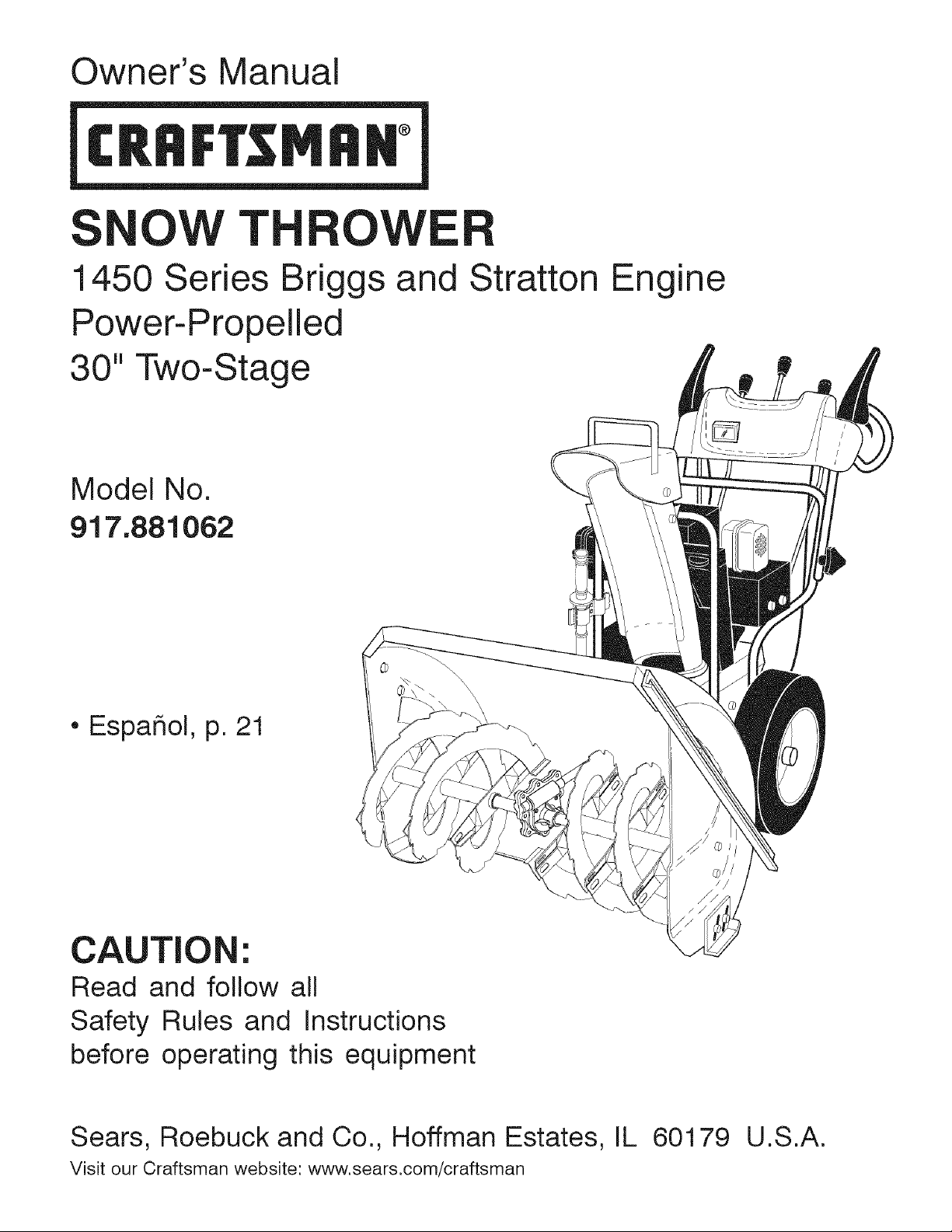
SNOW THROWER
1450 Series Briggs and
Power-Propelled
30" Two-Stage
Model No.
917.881062
• EspaSol, p. 21
Stratton
Engine
CAUTIO ."
Read and follow all
Safety Rules and Instructions
before operating this equipment
Sears, Roebuck and Co., Hoffman Estates, IL 60179 U.S.A.
Visit our Craftsman website: www.sears.com/craftsman
IMPORTANT
Safe Operation Practices for Walk=Behind Snow Throwers
This snow thrower is capable of amputating hands and feet and throwing objects.
Failure to observe the following safety instructions could result in serious injury.
Look for this symbol to point out im-
portant safety precautions. It means
&
&
Training
1. Read, understand and follow all instructions on the
machine and in the manual(s) before operating this
unit. Be thoroughly familiar with the controls and the
proper use of the equipment. Know how to stop the
unit and disengage the controls quickly.
2. Never allow children to operate the equipment. Never
allow adults to operate the equipment without proper
instruction.
3. Keep the area of operation clear of all persons, par-
ticularly small children.
4. Exercise caution to avoid slipping or falling, especially
when operating the snow thrower in reverse.
Preparation
1. Thoroughly inspect the area where the equipment is
to be used and remove all doormats, sleds, boards,
wires, and other foreign objects.
2. Disengage all clutches and shift into neutral before
starting the engine (motor).
3. Donotoperatethe equipmentwithoutwearing adequate
winter garments. Avoid loose fitting clothing that can
get caught in moving parts. Wear footwear that will
improve footing on slippery surfaces.
4. Handle fuel with care; it is highly flammable
(a) Use an approved fuel container.
(b) Never add fuel to a running engine or hot en-
(c) Fill fuel tank outdoors with extreme care. Never fill
(d) Never fill containers inside a vehicle or on a truck
(e) When practical, remove gas-powered equipment
CAUTION!!! BEOOMEALERT!!! YOUR
SAFETY IS INVOLVED.
WARNING: Always disconnect spark
plug wire and place it where it cannot
contact plug in order to prevent acci-
dental starting when setting up, trans-
porting, adjusting or making repairs.
WARNING: This snow thrower is for
use on sidewalks, driveways and other
be exercised while using on sloping sur-
faces, Do not use snow thrower on
ground level surfaces. Caution should
surfaces above ground level such as
roofs of residences, garages, porches
or other such structures or buildings.
gine.
fuel tank indoors.
or trailer bed with a plastic liner. Always place
containers on the ground, away from your vehicle,
before filling.
from the truck or trailer and refuel it on the ground.
If this is not possible, then refuel such equipment
on a trailer with a portable container, rather than
from a gasoline dispenser nozzle.
WARNING: Snow throwers have ex-
posed rotating parts, which can cause
terial thrown from the discharge chute.
severe injury from contact, or from ma-
Keep the area of operation clear of all
persons, small children and pets at all
times including startup.
parts become extremely hot during
CAUTION: Muffler and other engine
operation and remain hot after engine
contact, stay away from these areas.
has stopped. To avoid severe burns on
WARNING: Engine exhaust, some of
components contain or emit chemi-
cals known to the State of California
its constituents, and certain vehicle
to cause cancer and birth defects or
other reproductive harm.
(f) Keep the nozzle in contact with the rim of the fuel
tank or container opening at all times, until refuel-
ing is complete. Do not use a nozzle lock-open
device.
(g) Replace gasoline cap securely and wipe upspilled
fuel.
(h) If fuel is spilled on clothing, change clothing im-
mediately.
5,
Use extension cords and receptacles as specified by
the manufacturer for all units with electric drive motors
or electric starting motors.
6,
Adjust the collector housing height to clear gravel or
crushed rock surface.
7.
Never attempt to make any adjustments while the
engine (motor) is running (except when specifically
recommended by manufacturer).
Always wear safety glasses or eye shields during op-
eration or while performing an adjustment or repair to
protect eyes from foreign objects that may be thrown
from the machine.
Operation
1. Do not put hands or feet near or under rotating parts.
Keep clear of the discharge opening at all times.
2. Exercise extreme caution when operating on or cross-
ing gravel drives, walks, or roads. Stay alert for hidden
hazards or traffic.
3. After striking a foreign object, stop the engine (motor),
remove the wire from the spark plug, disconnect the
cord on electric motors, thoroughly inspect the snow
thrower for any damage, and repair the damage before
restarting and operating the snow thrower.
4. If the unit should start to vibrate abnormally, stop the
engine (motor) and check immediately for the cause.
Vibration is generally a warning of trouble.
5. Stop the engine (motor) whenever you leave the oper-
ating position, before unclogging the collector/impeller
housing or discharge chute, and when making any
repairs, adjustments or inspections.
6. Whencleaning,repairingorinspectingthesnowthrower,
stoptheengineandmakecertainthecollector/impel-
lerandall movingpartshavestopped.Disconnect
thesparkplugwireandkeepthewireawayfromthe
plug.topreventsomeonefromaccidentallystartingthe
engine.
7. Donotruntheengineindoors,exceptwhenstarting
theengineandfortransportingthesnowthrowerinor
outofthebuilding.Opentheoutsidedoors;exhaust
fumesaredangerous.
8. Exerciseextremecautionwhenoperatingonslopes.
9. Neveroperatethesnowthrowerwithoutproperguards,
andothersafetyprotectivedevicesinplaceandwork-
ing.
10.Neverdirectthedischargetowardpeopleor areas
wherepropertydamagecanoccur.Keepchildrenand
othersaway.
11.Donotoverloadthemachinecapacitybyattempting
toclearsnowattoofastarate.
12.Neveroperatethemachineathightransportspeeds
onslipperysurfaces.Lookbehindandusecarewhen
operatinginreverse.
13.Disengagepowertothecollector/impellerwhensnow
throweristransportedornotinuse.
14.Useonlyattachmentsandaccessoriesapprovedby
themanufacturerofthesnowthrower(suchaswheel
weights,counterweights,orcabs).
15.Neveroperatethesnowthrowerwithoutgoodvisibility
orlight.Alwaysbesureofyourfooting,andkeepafirm
holdonthehandles.Walk;neverrun.
16.Nevertouchahotengineormuffler.
Clearing a Clogged Discharge Chute
Hand contact with the rotating impeller inside the discharge
chute is the most common cause of injury associated with
snow throwers. Never use your hand to clean out the dis-
charge chute. To clear the chute:
1. SHUTTHE ENGINE OFF!
2. Wait 10 seconds to be sure the impeller blades have
stopped rotating.
3. Always use a clean-out tool, not your hands.
Maintenance and Storage
1. Check shear bolts and other bolts at frequent intervals
for proper tightness to be sure the equipment is in safe
working condition.
2. Never store the machine with fuel in the fuel tank
inside a building where ignition sources are present
such as hot water heaters, space heaters, or clothes
dryers. Allow the engine to cool before storing in any
enclosure.
3. Always refer to operator's manual for important details
if the snow thrower is to be stored for an extended
period.
4. Maintain or replace safety and instruction labels, as
necessary.
5. Run the machine a few minutes after throwing snow
to prevent freeze-up of the collector/impeller.
TABLE OF CONTENTS
SAFETY RULES ........................................................ 2-3
PRODUCT SPECIFICATIONS ...................................... 4
CUSTOMER RESPONSiBiLITIES ................................ 4
WARRANTY .................................................................. 4
ASSEMBLY / PRE-OPERATION ............................... 6-8
OPERATION ............................................................ 9=14
MAINTENANCE ..................................................... 15-16
MAINTENANCE SCHEDULE ..................................... 15
SERVICE AND ADJUSTMENTS ........................... 17=19
STORAGE ................................................................... 19
TROUBLESHOOTING ................................................ 20
REPAIR PARTS ..................................................... 40-55
SEARS SERVICE ................................... BACK COVER
UMITED2=YEARWARRANTY ON CRAFTSMAN SNOW THROWER
When used and maintained according to the operator's manual instructions, if this snow thrower fails due to a
defect in material or workmanship within two years from the date of purchase, call 1-800-4-MY-HOME® to arrange
for free repair.
During the first 30 days of purchase, there will be no charge to service the product in your home. For your
convenience, in-home warranty service will still be available after the first 30 days of purchase, but a trip charge
will apply. This charge will be waived if you transport the product to an authorized Craftsman drop-off location, For
the nearest authorized location, call 1-800-4-MY-HOME®,
Warranty coverage does not include:
• Expendable items that become worn during normal use, including but not limited to spark plugs, shear pins, belts,
• Standard maintenance servicing, oil changes, or tune-ups.
• Tire replacement or repair caused by punctures from outside objects, such as nails, thorns, stumps, or glass.
• Repairs necessary because of operator abuse, including but not limited to damage caused by impacting objects
that bend the frame, crankshaft or auger, or over-speeding the engine.
• Repairs necessary because of operator negligence, including but not limited to damage caused by improper
storage, failure to use the proper grade and amount of engine oil, or failure to maintain the equipment according
to the instructions contained in the operator's manual
• Engine (fuel system) cleaning or repairs necessary because of fuel determined to be contaminated or oxidized
(stale). In general, fuel should be used within 30 days of its purchase date.
• Normal deterioration and wear of the exterior finishes, or product label replacement,
This warranty applies for only 90 days if this product is used for commercial or rental purposes.
This warranty applies only while this product is within the United States.
This warranty gives you specific legal rights, and you may also have other rights, which vary, from state to state.
Seats, Roebuck And Co., Hoffman Estates, IL 60179
CONGRATULATIONS on your purchase of a new snow
thrower. It has been designed, engineered and manufac-
tured to give best possible dependability and performance.
Should you experience any problem you cannot eas-
ily remedy, please contact your nearest Sears Parts &
Repair Center. We have competent, well-trained tech-
nicians and the proper tools to service or repair this unit.
Please read and retain this manual. The instructions
will enable you to assemble and maintain your snow
thrower properly. Always observe the "SAFETY RULES",
SERIAL NUMBER:
DATE OFPURCHASE:
THE MODELAND SERIAL NUMBERSWILL BE FOUND
ONA DECALATTACH EDTOTHE REAR OFTHE SNOW
THROWER HOUSING.
YOUSHOULDRECORDBOTHSERIALNUMBERAND
DATE OF PURCHASE AND KEEPIN A SAFE PLACE
FOR FUTURE REFERENCE.
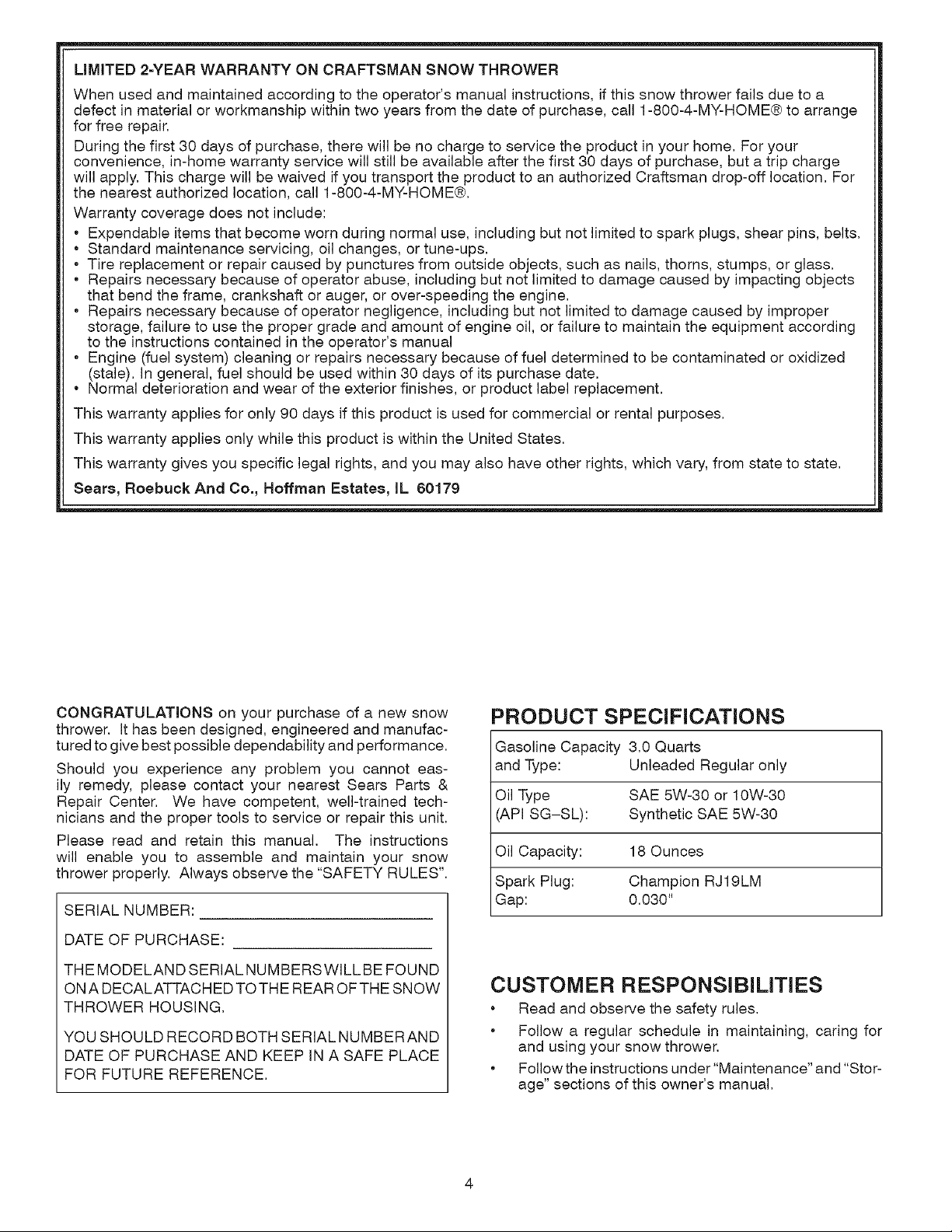
PRODUCT SPECiFiCATiONS
Gasoline Capacity 3.0 Quarts
and Type: Unleaded Regular only
Oil Type SAE 5W-30 or 10W-30
(API SG-SL): Synthetic SAE 5W-30
Oil Capacity: 18 Ounces
Spark Plug: Champion RJ19LM
Gap: 0,030"
CUSTOMER RESPONSIBiLITiES
• Read and observe the safety rules.
• Follow a regular schedule in maintaining, caring for
and using your snow thrower.
• Follow the instructions under "Maintenance" and "Stor-
age" sections of this owner's manual.

PARTS PACKED SEPARATELY I CARTON
(1) POWER
(1) DISCHARGE CHUTE
EXTRA SHEAR BOLTS AND NUTS
CORD
(1) FUEL STABiLiZER PACKET
START I
(2) SAFETY iGNiTiON KEYS
(1) AUGER CONTROL ROD
(1) TRACTION DRIVE CONTROL ROD _
7
I
I
©
I
(1) MULTi=
WRENCH
(2) SHEAR BOLTS 1/4=20 x 1=3/4
ROTATOR HEAD MOUNTING
(1) WASHER 3/8 (1) LOCKNUT 3/8
(1) LOCKNUT
5/16=18
(1) CARRIAGE
BOLT 5/16=18 × 5/8
(2) SPACERS (2) LOCKNUTS
1/4=20
I
I
I
I
I
J
CHUTE DEFLECTOR REMOTE CONTROL
(1) LOCKNUT (1) NYLON
1/4=20 WASHER
I
I
(3) RETAINER
SPRINGS
(1) SHOULDER
BOLT 1/4=20 (1) SPRING
AS / RE-O ERATION
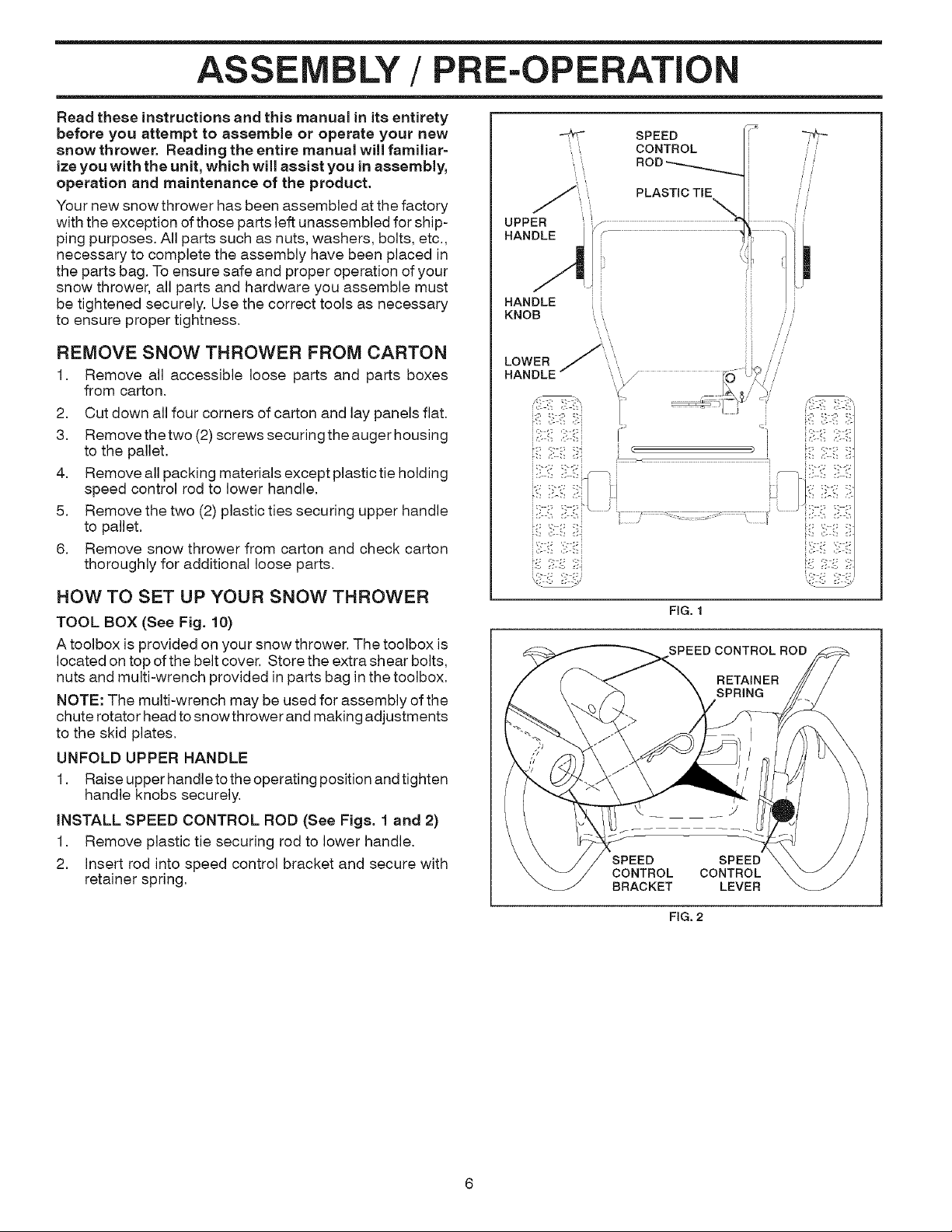
Read these instructions and this manual in its entirety
before you attempt to assemble or operate your new
snow thrower. Reading the entire manual will familiar=
ize you with the unit, which will assist you in assembly,
operation and maintenance of the product.
Your new snow thrower has been assembled at the factory
with the exception of those parts left unassembled for ship-
ping purposes. All parts such as nuts, washers, bolts, etc.,
necessary to complete the assembly have been placed in
the parts bag. To ensure safe and proper operation of your
snow thrower, all parts and hardware you assemble must
be tightened securely. Use the correct tools as necessary
to ensure proper tightness.
REMOVE SNOW THROWER FROM CARTON
1. Remove all accessible loose parts and parts boxes
from carton.
2. Cut down all four corners of carton and lay panels flat.
3. Remove the two (2) screws securing the auger housing
to the pallet.
4. Remove all packing materials except plastic tie holding
speed control rod to lower handle.
5. Remove the two (2) plastic ties securing upper handle
to pallet.
6. Remove snow thrower from carton and check carton
thoroughly for additional loose parts.
UPPER
HANDLE
HANDLE
KNOB
LOWER
HANDLE
i _ _ i
/ ,/
/' /
HOW TO SET UP YOUR SNOW THROWER
TOOL BOX (See Fig. 10)
A toolbox is provided on your snow thrower. The toolbox is
located on top of the belt cover. Store the extra shear bolts,
nuts and multi-wrench provided inparts bag in the toolbox.
NOTE: The multi-wrench may be used for assembly of the
chute rotator head to snow thrower and making adjustments
to the skid plates.
UNFOLD UPPER HANDLE
1. Raise upper handle tothe operating position and tighten
handle knobs securely.
INSTALL SPEED CONTROL ROD (See Figs. 1 and 2)
1. Remove plastic tie securing rod to lower handle.
2. Insert rod into speed control bracket and secure with
retainer spring.
FIG. 1
SPEED CONTROL ROD
RETAINER
SPRING
SPEED SPEED
CONTROL CONTROL
BRACKET LEVER
FIG. 2
AS / RE-O ERATION
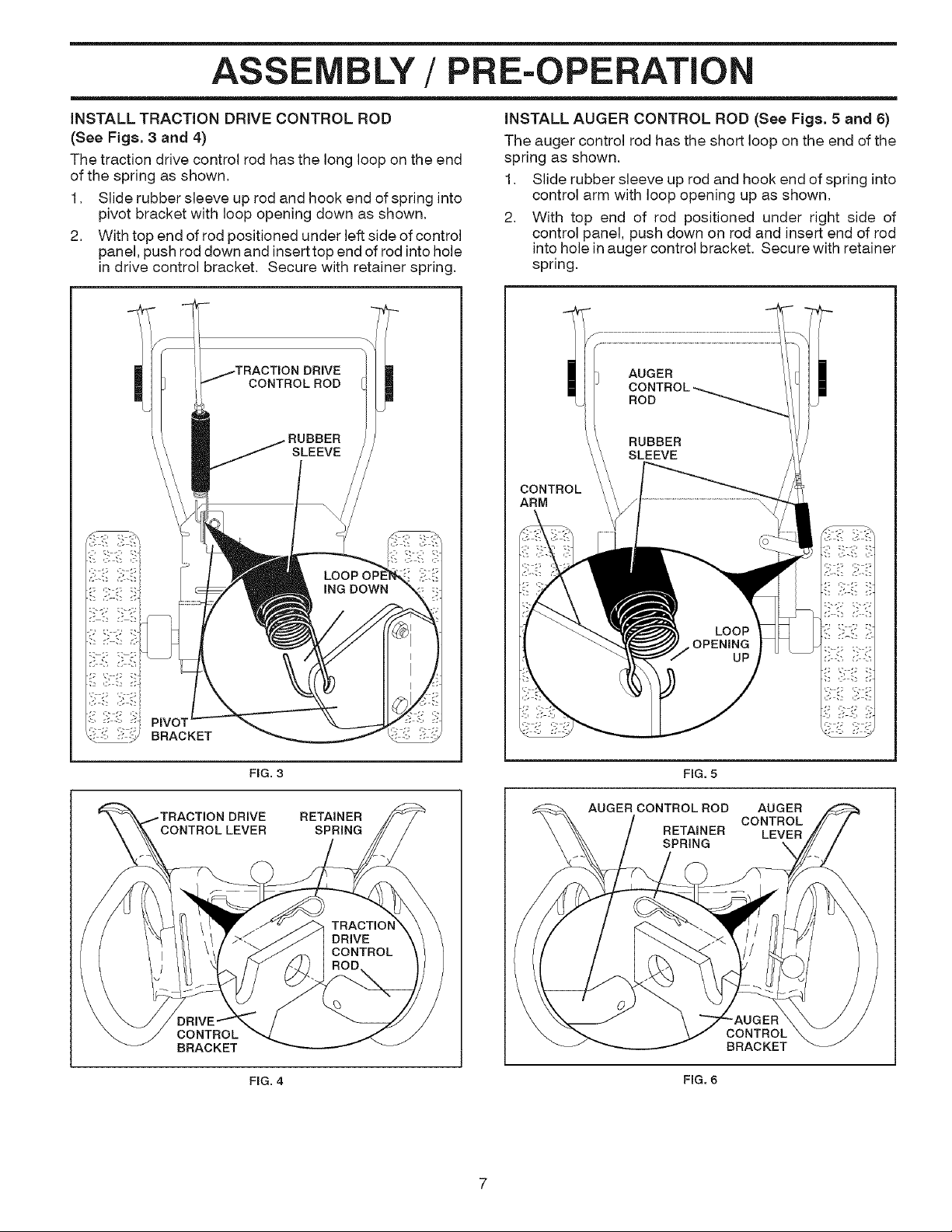
INSTALL TRACTION DRIVE CONTROL ROD
(See Figs. 3 and 4)
The traction drive control rod has the long loop on the end
of the spring as shown.
1. Slide rubber sleeve up rod and hook end of spring into
pivot bracket with loop opening down as shown.
2. With top end of rod positioned under left side of control
panel, push rod down and insert top end of rod into hole
in drive control bracket. Secure with retainer spring.
INSTALL AUGER CONTROL ROD (See Figs. 5 and 6)
The auger control rod has the short loop on the end of the
spring as shown.
1. Slide rubber sleeve up rod and hook end of spring into
control arm with loop opening up as shown.
2. With top end of rod positioned under right side of
control panel, push down on rod and insert end of rod
into hole in auger control bracket. Secure with retainer
spring.
AUGER
ROD
RUBBER
SLEEVE
CONTROL
ARM
CONTROL
BRACKET
FIG. 3
FIG, 4
RETAINER
SPRING
FIG. 5
AUGER CONTROL ROD AUGER
CONTROL
RETAINER LEVER
SPRING \
CONTROL
BRACKET
FIG. 6
AS BLY / RE..O ERATION
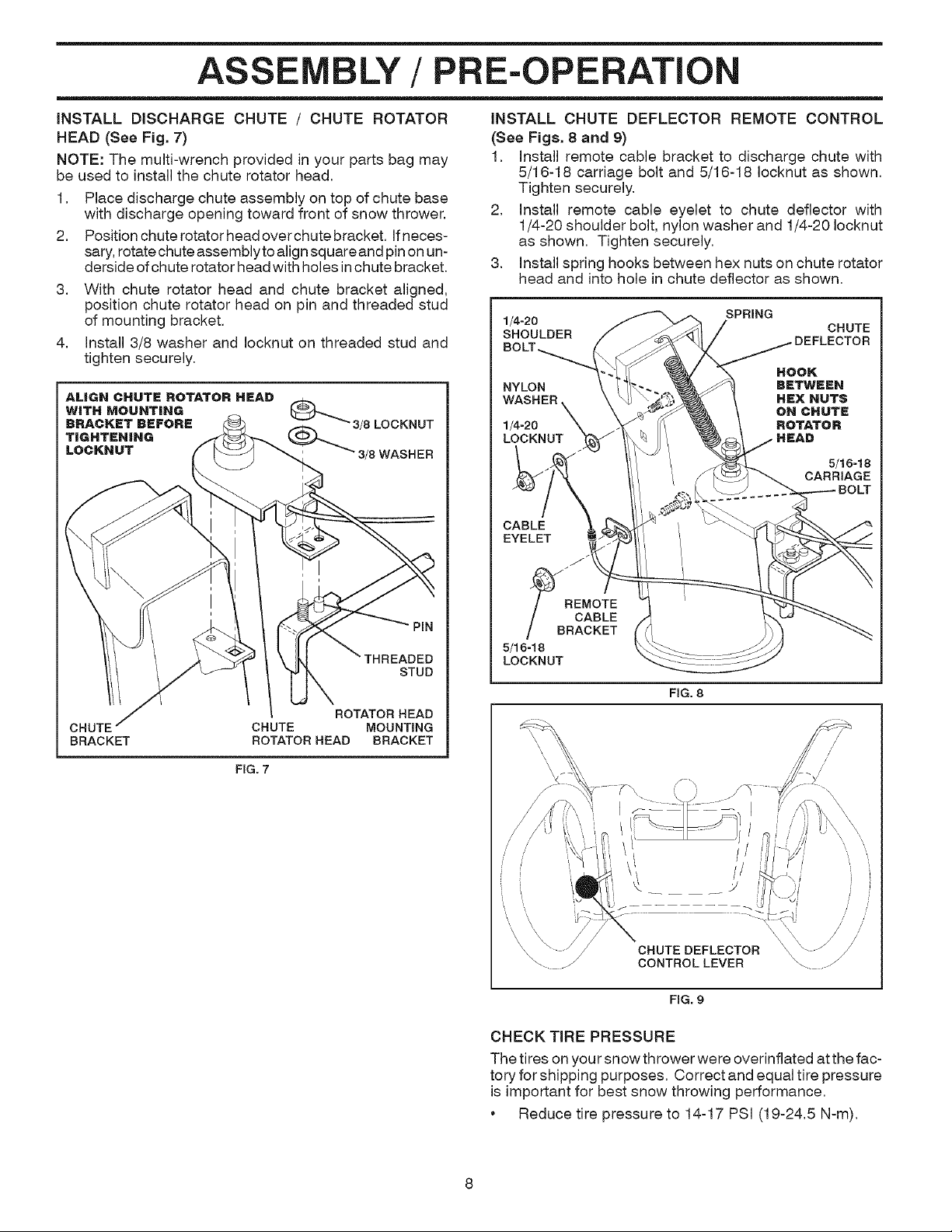
iNSTALL DISCHARGE CHUTE / CHUTE ROTATOR
HEAD (See Fig. 7)
NOTE: The multi-wrench provided in your parts bag may
be used to install the chute rotator head,
1, Place discharge chute assembly on top of chute base
with discharge opening toward front of snow thrower,
2, Position chute rotator head overchute bracket, Ifneces-
sary, rotate chute assembly toalign square and pin on un-
derside of chute rotator head with holes inchute bracket,
3, With chute rotator head and chute bracket aligned,
position chute rotator head on pin and threaded stud
of mounting bracket,
4, Install 3/8 washer and Iocknut on threaded stud and
tighten securely,
iNSTALL CHUTE DEFLECTOR REMOTE CONTROL
(See Figs. 8 and 9)
1, Install remote cable bracket to discharge chute with
5/16-18 carriage bolt and 5/16-18 Iocknut as shown,
Tighten securely,
2, Install remote cable eyelet to chute deflector with
1/4-20 shoulder bolt, nylon washer and 1/4-20 Iocknut
as shown, Tighten securely,
3, Install spring hooks between hex nuts on chute rotator
head and into hole in chute deflector as shown,
1/4-20 CHUTE
SHOULDER
NYLON BETWEEN
WASHER HEX HUTS
1/4-20 ROTATO R
LOCKNUT
CABLE
EYELET
SPRING
HOOK
ON CHUTIE
5/16- ! 8
CARRIAGE
BOLT
CHUTE
BRACKET
CHUTE MOUNTING
ROTATOR HEAD
ROTATOR HEAD BRACKET
FiG. 7
PIN
STUD
L _EMOTE
CABLE
RACKET
5/16-18
LOCKNUT
FiG. 8
//
/
/
/
/'
I
CHUTE DEFLECTOR
CONTROL LEVER
FIG, 9
CHECK TiRE PRESSURE
The tires on your snow thrower were overinflated atthe fac-
tory for shipping purposes. Correct and equal tire pressure
is important for best snow throwing performance,
• Reduce tire pressure to 14-17 PSi (19-24,5 N-m),
OPERATION
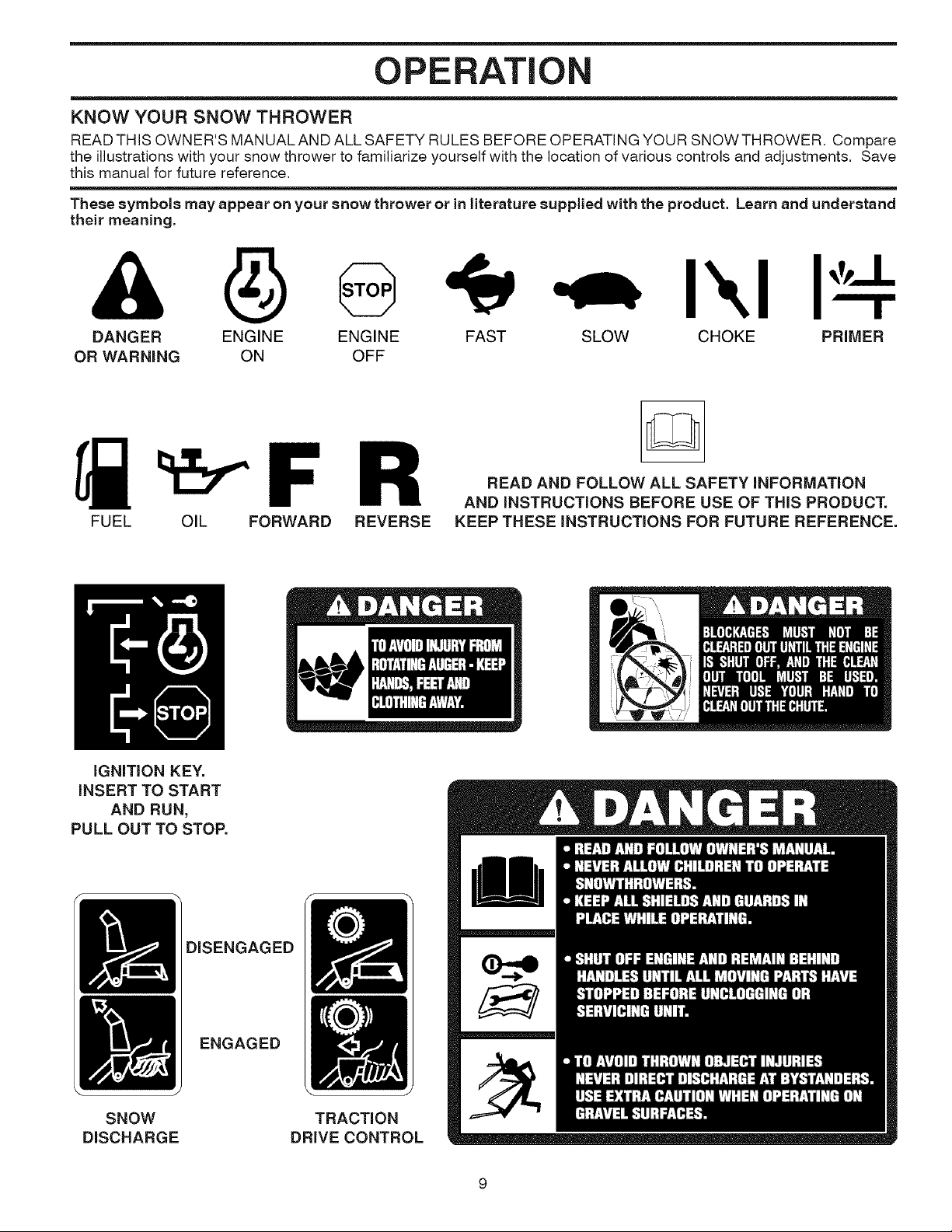
KNOW YOUR SNOW THROWER
READ THIS OWNER'S MANUALAND ALL SAFETY RULES BEFORE OPERATING YOUR SNOWTHROWER. Compare
the illustrations with your snow thrower to familiarize yourself with the location of various controls and adjustments, Save
this manual for future reference,
These symbols may appear on your snow thrower or in literature supplied with the product. Learn and understand
their meaning,
I\1
DANGER ENGINE FAST SLOW CHOKE PRIMER
OR WARNING ON
FUEL OIL FORWARD REVERSE
iGNITiON KEY.
INSERT TO START
AND RUN,
PULL OUT TO STOP.
ENGINE
OFF
R
READ AND FOLLOW ALL SAFETY INFORMATION
AND iNSTRUCTiONS BEFORE USE OF THIS PRODUCT.
KEEP THESE INSTRUCTIONS FOR FUTURE REFERENCE.
\ J
SNOW
DISCHARGE
DISENGAGED
ENGAGED
_J
TRACTION
DRIVECONTROL
OPERATION
GASOLINE ELECTRIC AUGER DISCHARGE CHUTE CONTROL LEVER
CHOKE DEFLECTOR CONTROL
CONTROL LEVER
SAFETY
IGNITION
KEY
NOTE: ITEMS ABOVE
ARE SHOWN IN
THEIR TYPICAL
LOCATION ON THE
ENGINE. ACTUAL
LOCATION MAY VARY
WITH THE ENGINE
ON YOUR UNIT.
ON / OFF
SWITCH
CLEAN-OUT TOOL
\
\
\
START BUTTON CONTROL
RECOIL X CONTROL LEVER CONTROL LEVER
STARTER
HANDLE
CHUTE
LEVER DRIVE SPEED DEFLECTOR REMOTE
\
CHUTE DRIVE
TRACTION
LH TURN
TRIGGER
LIGHT
KNOB
TOOLBOX
AUGERS
FIG. 10
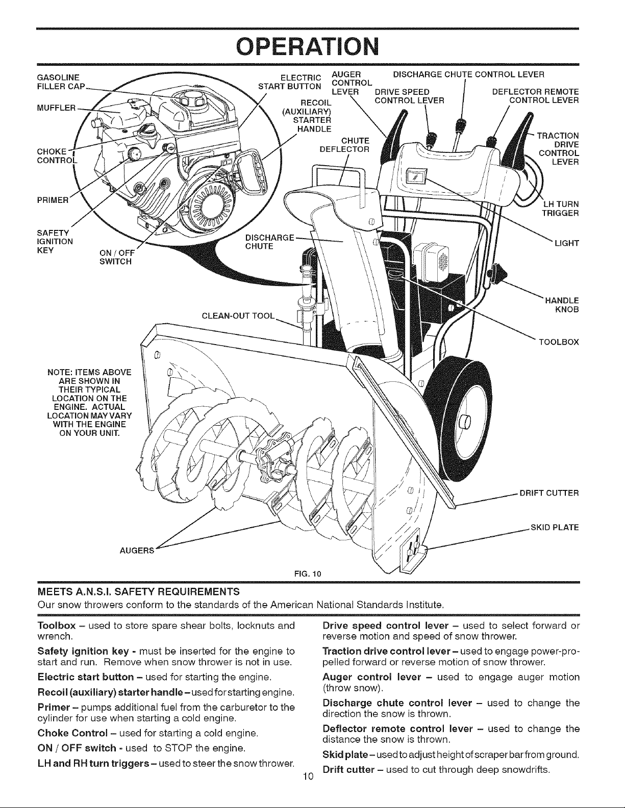
MEETS A,N,S,I, SAFETY REQUIREMENTS
Our snow throwers conform to the standards of the American National Standards institute,
Toolbox - used to store spare shear bolts, Iocknuts and
wrench,
Safety ignition key = must be inserted for the engine to
start and run, Remove when snow thrower is not in use,
Electric start button - used for starting the engine,
Recoil (auxiliary) starter handle-used for starting engine,
Primer - pumps additional fuel from the carburetor to the
cylinder for use when starting a cold engine.
Choke Control - used for starting a cold engine.
ON / OFF switch = used to STOP the engine.
LH and RH turn triggers- used to steer the snow thrower.
Drive speed control lever = used to select forward or
reverse motion and speed of snow thrower,
Traction drive control lever- used to engage power-pro-
pelled forward or reverse motion of snow thrower,
Auger control lever - used to engage auger motion
(throw snow),
Discharge chute control lever - used to change the
direction the snow is thrown,
Deflector remote control lever - used to change the
distance the snow is thrown,
Skid plate - used to adjust height of scraper bar from ground,
Drift cutter - used to cut through deep snowdrifts,
10
DRIFT CUTTER
PLATE

OPERATION
The operation of any snow thrower can result
in foreign objects thrown into the eyes, which
can result insevere eyedamage. Always wear
safety glasses or eye shields while operating
your snow thrower or performing any adjust-
ments or repairs. We recommend standard safety glasses
or a wide vision safety mask worn over spectacles.
HOW TO USE YOUR SNOW THROWER
Know how to operate all controls before adding fuel or
attempting to start the engine.
STOPPING
TRACTION DRIVE
• Release traction drive control lever to stop the forward
or reverse movement of the snow thrower.
AUGER
• Release the auger control lever to stop throwing snow.
ENGINE
1. Move ON / OFF switch to "OFF" position.
2. Remove (do not turn) safety ignition key to prevent
unauthorized use.
NOTE: Never use choke to stop engine.
TO USE CHOKE CONTROL (See Fig. 11)
The choke control is located on the engine. Use the choke
control whenever you are starting a cold engine. Do not
use to start a warm engine.
• To engage choke, turn knob counterclockwise. Slowly
turn knob clockwise to disengage.
TO CONTROL SNOW DISCHARGE (See Fig, 12)
WARNING: Snow throwers have ex-
posed rotating parts, which can cause
terial thrown from the discharge chute.
severe injury from contact, or from ma-
Keep the area of operation cJear of all
persons, small children and pets at all
times including startup.
WARNING: if the discharge chute or
and wait for all moving parts to stop, Use
auger become clogged, shut-off engine
the clean=out tool, NOT YOUR HANDS,
to unclog the chute and/or auger.
The DIRECTION inwhich snow isto be thrown is controlled
by the discharge chute control lever.
• Tochangethe discharge chute position, press downward
on discharge chute control lever and move lever left
or right until chute is in desired position. Be sure lever
springs back and locks into desired position.
The DISTANCE that snow is thrown is controlled by the
position of the chute deflector. Set the deflector low to
throw snow a short distance; set the deflector higher to
throw snow farther.
Press downward on chute deflector control lever and
move lever forward to lower the deflector and decrease
the distance. Move lever back to raise the deflector
and increase the distance. Be sure lever springs back
and locks into desired position.
DlSCHARGECHUTE
CONTROLLEVER
FIG. 11
CHUTE DEFLECTOR
REMOTE CONTROLLEVER
FIG, 12
11
OPERATION
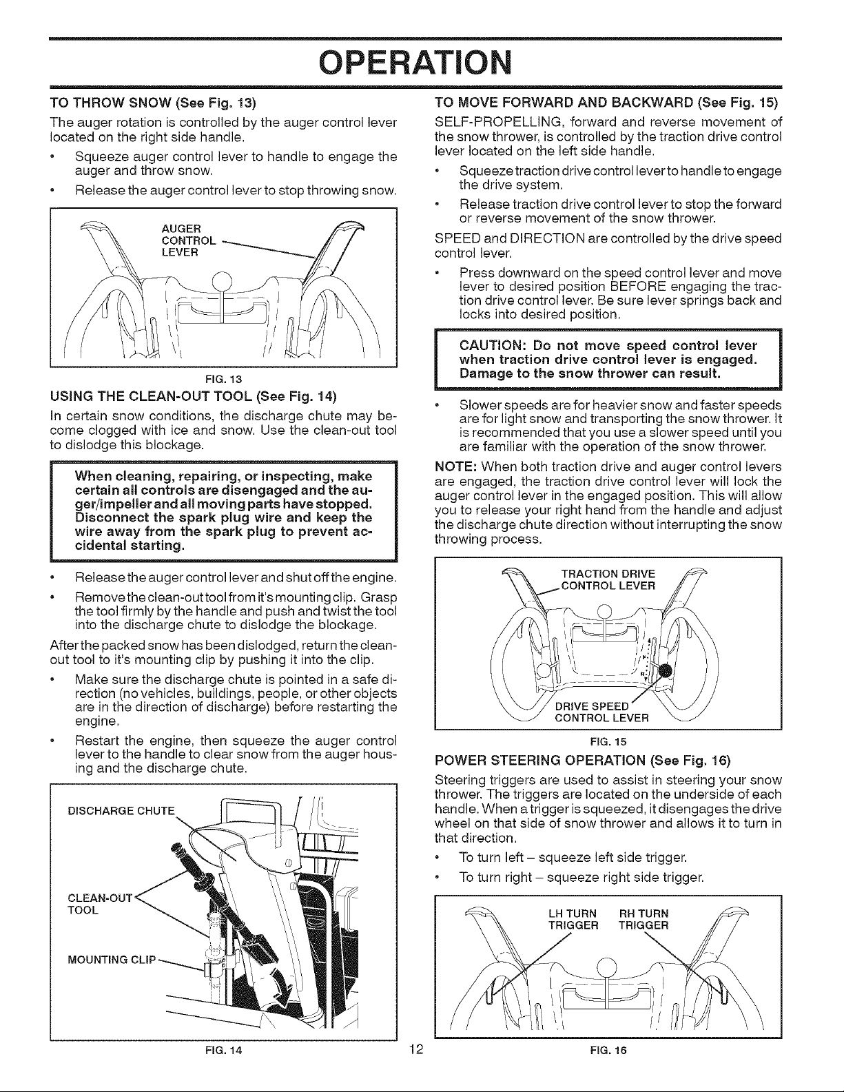
TO THROW SNOW (See Fig, 13)
The auger rotation is controlled by the auger control lever
located on the right side handle.
• Squeeze auger control lever to handle to engage the
auger and throw snow.
• Release the auger control lever to stop throwing snow.
FIG, 13
USING THE CLEAN-OUT TOOL (See Fig, 14)
In certain snow conditions, the discharge chute may be-
come clogged with ice and snow, Use the clean-out tool
to dislodge this blockage,
When cleaning, repairing, or inspecting, make
certain all controls are disengaged and the au-
ger/impeller and all moving parts have stopped,
Disconnect the spark plug wire and keep the
wire away from the spark plug to prevent ac-
cidental starting,
TO MOVE FORWARD AND BACKWARD (See Fig. 15)
SELF-PROPELLING, forward and reverse movement of
the snow thrower, is controlled by the traction drive control
lever located on the left side handle.
• Squeeze traction drive control lever to handle to engage
the drive system,
• Release traction drive control lever to stop the forward
or reverse movement of the snow thrower,
SPEED and DIRECTION are controlled by the drive speed
control lever.
• Press downward on the speed control lever and move
lever to desired position BEFORE engaging the trac-
tion drive control lever. Be sure lever springs back and
locks into desired position,
• Slower speeds are for heavier snow and faster speeds
are for light snow and transporting the snow thrower. It
is recommended that you use a slower speed until you
are familiar with the operation of the snow thrower.
NOTE: When both traction drive and auger control levers
are engaged, the traction drive control lever will lock the
auger control lever in the engaged position. This will allow
you to release your right hand from the handle and adjust
the discharge chute direction without interrupting the snow
throwing process,
• Releasethe auger control lever and shut offthe engine.
• Removethe clean-out tool from it'smounting clip. Grasp
the tool firmly bythe handle and push and twist the tool
into the discharge chute to dislodge the blockage.
After the packed snow has been dislodged, return the clean-
out tool to it's mounting clip by pushing it into the clip.
• Make sure the discharge chute is pointed in a safe di-
rection (no vehicles, buildings, people, or other objects
are in the direction of discharge) before restarting the
engine.
• Restart the engine, then squeeze the auger control
lever to the handle to clear snow from the auger hous-
ing and the discharge chute.
DISCHARGECHUTE
TOOL
MOUNTING
I
TRACTION DRIVE //_
CONTROLLEVER
FIG. 15
POWER STEERING OPERATION (See Fig, 16)
Steering triggers are used to assist in steering your snow
thrower. The triggers are located on the underside of each
handle. When atrigger is squeezed, it disengages the drive
wheel on that side of snow thrower and allows it to turn in
that direction.
• To turn left- squeeze left side trigger,
• To turn right - squeeze right side trigger,
LH TURN
TRIGGER
FIG, 14 12 FIG. 16
OPERATION
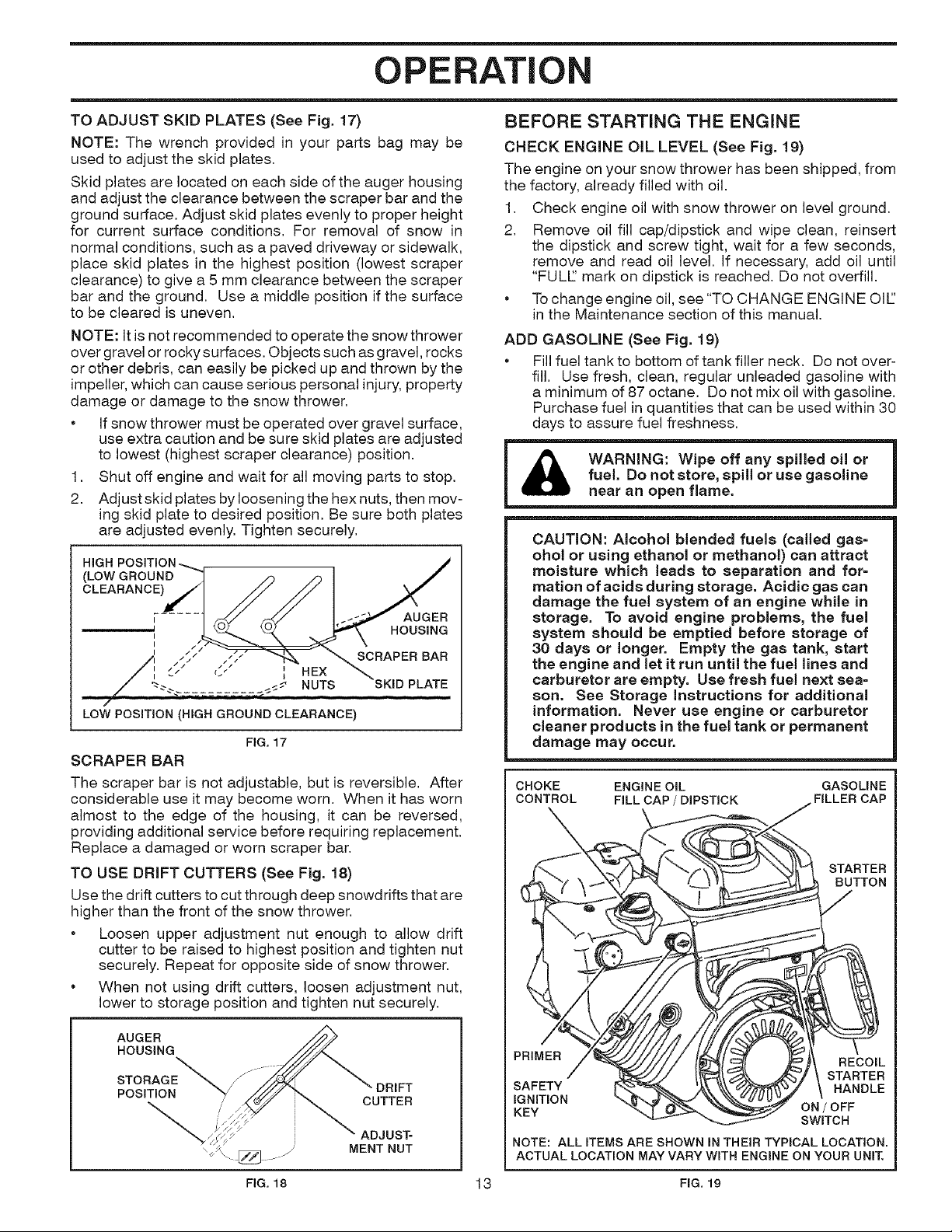
TO ADJUST SKiD PLATES (See Fig. 17)
NOTE: The wrench provided in your parts bag may be
used to adjust the skid plates.
Skid plates are located on each side of the auger housing
and adjust the clearance between the scraper bar and the
ground surface. Adjust skid plates evenly to proper height
for current surface conditions. For removal of snow in
normal conditions, such as a paved driveway or sidewalk,
place skid plates in the highest position (lowest scraper
clearance) to give a 5 mm clearance between the scraper
bar and the ground. Use a middle position if the surface
to be cleared is uneven.
NOTE: It is not recommended to operate the snow thrower
over gravel or rocky surfaces. Objects such as gravel, rocks
or other debris, can easily be picked up and thrown by the
impeller, which can cause serious personal injury, property
damage or damage to the snow thrower.
• If snow thrower must be operated over gravel surface,
use extra caution and be sure skid plates are adjusted
to lowest (highest scraper clearance) position.
1. Shut off engine and wait for all moving parts to stop.
2. Adjust skid plates by loosening the hex nuts, then mov-
ing skid plate to desired position. Be sure both plates
are adjusted evenly. Tighten securely.
(LOW GROUND
_)
AUGER
HOUSING
SCRAPER BAR
I HEX
_¢ NUTS PLATE
LOW POSITION (HIGH GROUND CLEARANCE)
FIG, 17
SCRAPER BAR
The scraper bar is not adjustable, but is reversible. After
considerable use it may become worn. When it has worn
almost to the edge of the housing, it can be reversed,
providing additional service before requiring replacement,
Replace a damaged or worn scraper bar.
TO USE DRIFT CUTTERS (See Fig. 18)
Use the drift cutters to cut through deep snowdrifts that are
higher than the front of the snow thrower.
• Loosen upper adjustment nut enough to allow drift
cutter to be raised to highest position and tighten nut
securely. Repeat for opposite side of snow thrower.
• When not using drift cutters, loosen adjustment nut,
lower to storage position and tighten nut securely.
BEFORE STARTING THE ENGINE
CHECK ENGINE OiL LEVEL (See Fig. 19)
The engine on your snow thrower has been shipped, from
the factory, already filled with oil.
1. Check engine oil with snow thrower on level ground.
2. Remove oil fill cap/dipstick and wipe clean, reinsert
the dipstick and screw tight, wait for a few seconds,
remove and read oil level. If necessary, add oil until
"FULL:.'mark on dipstick is reached. Do not overfill.
• Tochange engine oil, see "TO CHANGE ENGINE OIE'
in the Maintenance section of this manual.
ADD GASOLINE (See Fig. 19)
• Fill fuel tank to bottom of tank filler neck. Do not over-
fill. Use fresh, clean, regular unleaded gasoline with
a minimum of 87 octane. Do not mix oil with gasoline.
Purchase fuel in quantities that can be used within 30
days to assure fuel freshness.
fuel. Do not store, spill or use gasoline
WARNING: Wipe off any spilled oil or
near an open flame.
CAUTION: Alcohol blended fuels (called gas-
ohol or using ethanol or methanol) can attract
moisture which leads to separation and for-
mation of acids during storage. Acidic gas can
damage the fuel system of an engine while in
storage. To avoid engine problems, the fuel
system should be emptied before storage of
30 days or longer. Empty the gas tank, start
the engine and let it run until the fuel lines and
carburetor are empty. Use fresh fuel next sea-
son. See Storage instructions for additional
information. Never use engine or carburetor
cleaner products in the fuel tank or permanent
damage may occur.
CHOKE ENGINE OIL GASOLINE
CONTROL FILL CAP / DiPSTiCK FILLER CAP
STARTER
BUTTON
AUGER
HOUSING
STcORTIAoGE_
PRIMER RECOIL
DRIFT
CUTTER
ADJUST
MENT NUT
FIG, 18 13 FIG, 19
SAFETY HANDLE
IGNITION ON / OFF
KEY SWITCH
NOTE: ALL ITEMS ARE SHOWN IN THEIR TYPICAL LOCATION.
ACTUAL LOCATION MAY VARY WITH ENGINE ON YOUR UNIT.
STARTER
OPERATION
TO START ENGINE 5. Pull recoil starter handle quickly. Do not allow starter
Your snow thrower engine is equipped with both a 120 Volt
A.C. electric starter and a recoil starter. The electric starter
is equipped with a three-wire power cord and plug and is
designed to operate on 120 Volt A.C. household current.
• Be sure your house is a 120 Volt A.C. three-wire
grounded system. If you are uncertain, consult a
licensed electrician.
WARNING: Do not use the electric
A.C. three=wire grounded system. Se=
starter if your house is not a 120 Volt
rious personal injury or damage to your
snow thrower could result.
COLD START- ELECTRIC STARTER
1. Insert safety ignition key (packed separately in parts
bag) into ignition slot until it clicks. DO NOTtum the key.
Keep the extra safety ignition key in a safe place.
2. Place ON / OFF switch in "ON" position.
3. Rotate choke control to "FULl" position.
4. Connect the power cord to the engine.
5. Plug the other end of the power cord into a three-hole
grounded 120 Volt A.C. receptacle.
NOTE: Do not use primer when starting engine with the
electric starter.
6. Push starter button until engine starts.
IMPORTANT: Do not crank engine more than five con-
tinuous seconds between each time you try to start. Wait
5 to 10 seconds between each attempt.
7. When the engine starts, release the starter button and
slowly move the choke control to the "OFF" position.
8. Disconnect the power cord from the receptacle first,
then from the engine.
Allow the engine to warm up for a few minutes. Engine will
not develop full power until it has reached normal operat-
ing temperature.
WARM START - ELECTRIC STARTER
Follow the steps above, keeping the choke control in the
"OFF" position.
COLD START - RECOIL STARTER
1. Insert safety ignition key (packed separately in parts
bag) into ignition slot until it clicks. DO NOTturn the key.
Keep the extra safety ignition key in a safe place.
2. Place ON / OFF switch in "ON" position.
3. Rotate choke control to "FULl" position.
4. Push the primer four (4) times if the temperature is
below 15°F, or two (2)times if temperature is between
15° and 50°R Iftemperature is above 50°F, priming is
not necessary.
NOTE: Over priming may cause flooding, preventing the
engine from starting. If you do flood the engine, wait a few
minutes before attempting to start and DO NOT push the
primer.
rope to snap back.
6,
When the engine starts, release the recoil starter handle
and slowly move the choke control to the "OFF" posi-
tion.
Allow the engine to warm up for afew minutes. Engine will
not develop full power until it has reached normal operat-
ing temperature.
WARM START- RECOIL STARTER
Follow the steps above, keeping the choke in the "OFF"
position. DO NOT push the primer.
BEFORE STOPPING
Run the engine for a few minutes to help dry off any mois-
ture on the engine.
IF RECOIL STARTER HAS FROZEN
Ifthe recoil starter has frozen and will not turn the engine,
proceed as follows:
1. Grasp the recoil starter handle and slowly pull as much
rope out of the starter as possible.
2. Release the recoil starter handle and let it snap back
against the starter.
If the engine still fails to start, repeat the above steps or
use the electric starter.
SNOW THROWING TiPS
• Go slower in deep, freezing or heavy wet snow. Use
the drive speed control, NOT the ON / OFF switch, to
adjust speed.
• It is easier and more efficient to remove snow imme-
diately after it falls.
• The best time to remove snow is the early morning. At
this time the snow is usually dry and has not been ex-
posed to the direct sun and warming temperatures.
• Slightly overlap each successive path to ensure all
snow will be removed.
Throw snow downwind whenever possible.
Adjust the skid plates to proper height for current snow
conditions. See "TO ADJUST SKID PLATES" in this
section of this manual.
• For extremely heavy snow, reduce the width of snow
removal by overlapping previous path and moving
slowly.
, Keep engine clean and clear of snow during use. This
will help air flow and extend engine life.
, After snow-throwing iscompleted, allow engine to run for
a few minutes to melt snow and ice off the engine.
• Clean the entire snow thrower thoroughly after each
use and wipe dry so it is ready for next use.
thrower if weather conditions impair vis-
WARNING: Do not operate snow
ibility, Throwing snow during a heavy,
windy snowstorm can blind you and be
hazardous to the safe operation of the
snow thrower.
14
CE
HT Check for Loose Fasteners I_ I_
R Clean / Inspect Snow Thrower t1_ If
O
W Check/Replace V-Belts I_
Lubrication Chart I_ If
Check Engine Oil Level
E
N Change Engine Oil
Inspect Muffler
N Check / Replace Spark Plug
E
Empty Fuel Tank
v'
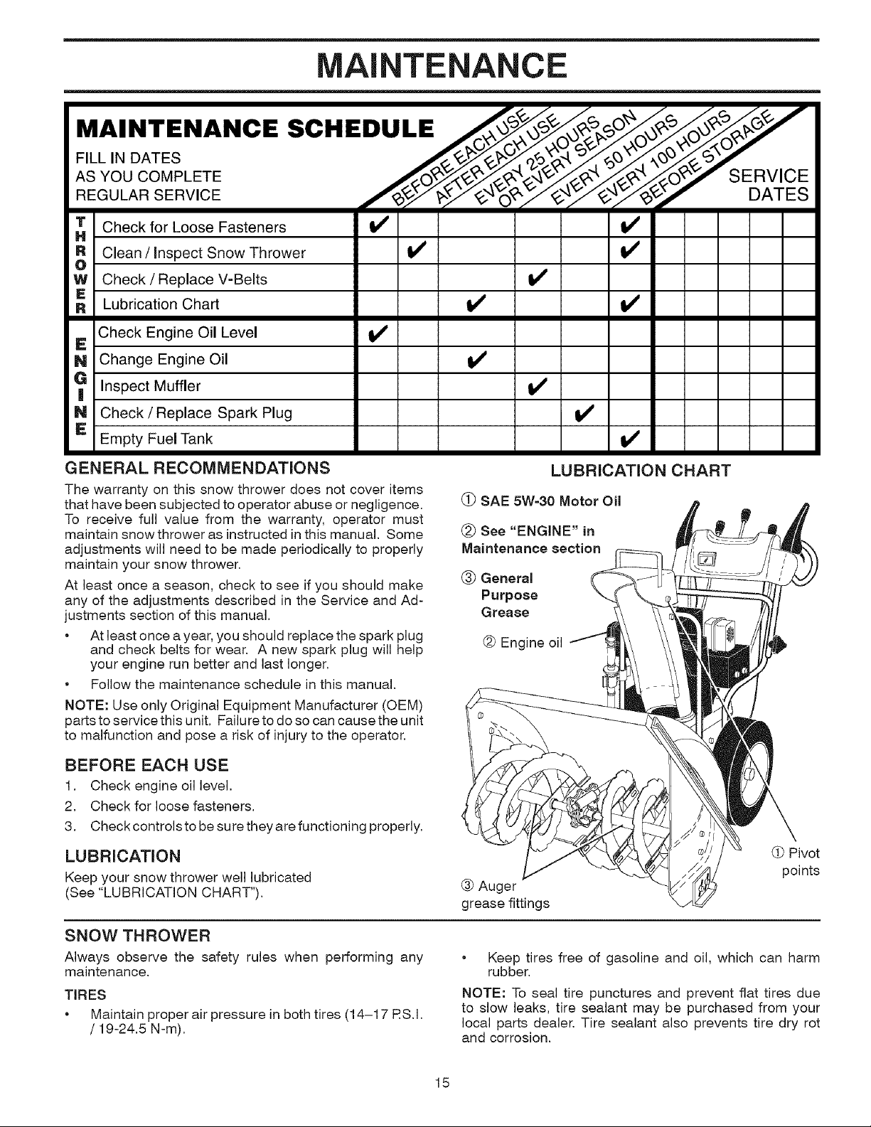
GENERAL RECOMMENDATIONS
The warranty on this snow thrower does not cover items
that have been subjected to operator abuse or negligence.
To receive full value from the warranty, operator must
maintain snow thrower as instructed in this manual. Some
adjustments will need to be made periodically to properly
maintain your snow thrower.
At least once a season, check to see if you should make
any of the adjustments described in the Service and Ad-
justments section of this manual.
• At least once a year, you should replace the spark plug
and check belts for wear. A new spark plug will help
your engine run better and last longer.
• Follow the maintenance schedule in this manual.
NOTE: Use only Original Equipment Manufacturer (OEM)
parts to service this unit. Failure to do so can cause the unit
to malfunction and pose a risk of injury to the operator.
t/
v'
v'
LUBRICATION CHART
(_ SAE 5W=30 Motor Oil
(_) See "ENGINE" in
Maintenance section
(_) General
Purpose
Grease
@ Engine oil
BEFORE EACH USE
1, Check engine oil level.
2. Check for loose fasteners.
3, Check controls to be sure they are functioning properly.
LUBRICATION
Keep your snow thrower well lubricated
(See "LUBRICATION CHART"),
SNOW THROWER
Always observe the safety rules when performing any
maintenance.
TIRES
• Maintain proper air pressure in both tires (14-17 RS.I.
/ 19-24.5 N-m).
O Pivot
points
Auger
grease fittings
Keep tires free of gasoline and oil, which can harm
rubber.
NOTE: To seal tire punctures and prevent flat tires due
to slow leaks, tire sealant may be purchased from your
local parts dealer. Tire sealant also prevents tire dry rot
and corrosion.
15
E
V-BELTS TO CHANGE ENGINE OIL
Check V-belts for deterioration and wear after every 50
hours of operation and replace if necessary. The belts
are not adjustable. Replace belts ifthey begin to slip from
wear. (See "TO REMOVE BELT COVER" in the Service
and Adjustments section of this manual).
The V-belts on your snow thrower are of special construction
and should be replaced byoriginal equipment manufacturer
(OEM) belts available from your nearest dealer. Using other
than OEM belts can cause personal injury or damage to
the snow thrower.
AUGER GEAR CASE
• The gear case was filled with lubricant to the proper
level at the factory. The only time the lubricant needs
attention is if service has been performed on the gear
case.
• If lubricant is required, use only Ronex ED #1 grease.
TRACTION DRIVE SYSTEM
DO NOT lubricate the drive components inside the snow
thrower. The sprockets, hex shafts, drive disc and friction
wheel require no lubrication. The bearings and bushings
are lifetime lubricated and require no maintenance.
CAUTION: Any lubricating of the above compo=
nents can cause contamination of the friction
wheel and damage to the drive system of your
snow thrower.
ENGINE
LUBRiCATiON
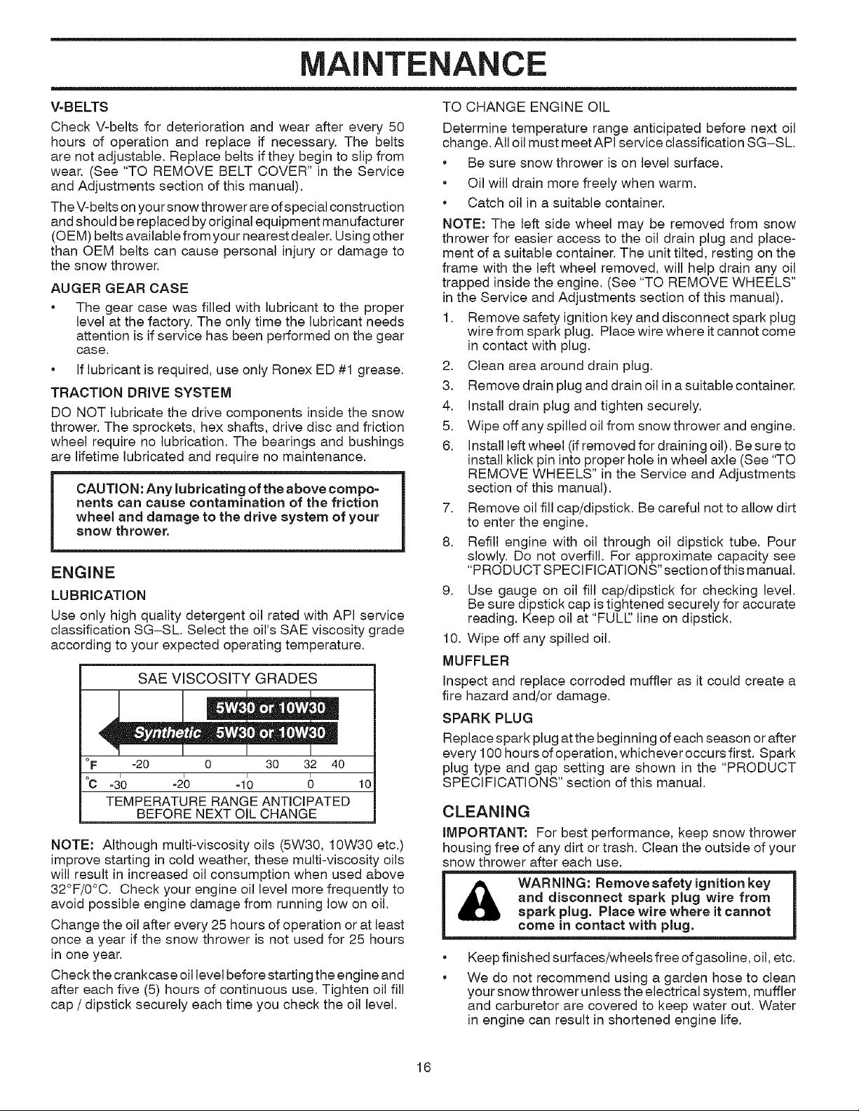
Use only high quality detergent oil rated with API service
classification SG-SL Select the oil's SAE viscosity grade
according to your expected operating temperature.
SAE VISCOSITY GRADES
°F -20 0 30 32 40
i°C -3'0 -20 =1'0 0
TEMPERATURE RANGE ANTICIPATED
BEFORE NEXT OiL CHANGE
NOTE: Although multi-viscosity oils (5W30, 10W30 etc.)
improve starting in cold weather, these multi-viscosity oils
will result in increased oil consumption when used above
32°F/0°C. Check your engine oil level more frequently to
avoid possible engine damage from running low on oil.
Change the oil after every 25 hours of operation or at least
once a year if the snow thrower is not used for 25 hours
in one year.
Check the crankcase oil level before starting the engine and
after each five (5) hours of continuous use. Tighten oil fill
cap / dipstick securely each time you check the oil level.
10
Determine temperature range anticipated before next oil
change. All oil must meet API service classification SG-SL.
• Be sure snow thrower is on level surface.
• Oil will drain more freely when warm.
• Catch oil in a suitable container.
NOTE: The left side wheel may be removed from snow
thrower for easier access to the oil drain plug and place-
ment of a suitable container. The unit tilted, resting on the
frame with the left wheel removed, will help drain any oil
trapped inside the engine. (See "TO REMOVE WHEELS"
in the Service and Adjustments section of this manual).
1. Remove safety ignition key and disconnect spark plug
wire from spark plug. Place wire where itcannot come
in contact with plug.
2. Clean area around drain plug.
3. Remove drain plug and drain oil in a suitable container.
4. Install drain plug and tighten securely.
5. Wipe off any spilled oil from snow thrower and engine.
6. Install left wheel (if removed for draining oil). Be sure to
install klick pin into proper hole in wheel axle (See "TO
REMOVE WHEELS" in the Service and Adjustments
section of this manual).
7. Remove oil fill cap/dipstick. Becareful not to allow dirt
to enter the engine.
8. Refill engine with oil through oil dipstick tube. Pour
slowly. Do not overfill. For approximate capacity see
"PRODUCT SPECIFICATIONS"section of this manual.
9. Use gauge on oil fill cap/dipstick for checking level.
Be sure dipstick cap istightened securely for accurate
reading. Keep oil at "FULL.' line on dipstick.
10. Wipe off any spilled oil.
MUFFLER
Inspect and replace corroded muffler as it could create a
fire hazard and/or damage.
SPARK PLUG
Replace spark plug at the beginning of each season or after
every 100 hours of operation, which ever occurs first. Spark
plug type and gap setting are shown in the "PRODUCT
SPECIFICATIONS" section of this manual.
CLEANING
iMPORTANT: For best performance, keep snow thrower
housing free of any dirt or trash, Clean the outside of your
snow thrower after each use.
-- come in contact with plug,
Keep finished surfaces/wheels free of gasoline, oil, etc.
We do not recommend using a garden hose to clean
your snow thrower unless the electrical system, muffler
and carburetor are covered to keep water out. Water
in engine can result in shortened engine life.
16
SERVICE ADJUSTMENTS
WARNING: To avoid serious injury, before
performing any service or adjustments:
1. Be sure the on/off switch is in the
OFF position.
2, Remove safety ignition key.3. Make sure the augers and all moving
parts have completely stopped.
4. Disconnect spark plug wire from
spark plug and place wire where it
cannot come in contact with plug.
SNOW THROWER
TO ADJUST SNOW THROWER HEIGHT
See "TO ADJUST SKID PLATES" and "SCRAPER BAR"
in the Operation section of this manual.
CHUTEDEFLECTOR
The chute deflector, attached to the top of the discharge
chute, is provided to direct discharging snow away from
the operator. If the deflector becomes damaged, it should
be replaced.
1. Disengage all controls and move throttle control to
STOP position. Wait for all moving parts to stop.
2. Remove safety ignition key and disconnect spark plug
wire from spark plug. Place wire where it cannot come
in contact with plug.
3. Align holes in impeller hub with holes in impeller shaft
and install two (2) new 1/4-20 x 1-5/8" capscrew/shear
bolts. Install 1/4-20 Iocknuts and tighten securely.
i CAUTION: Do not substitute. Use only original
J equipment capscrew/shear bolts as supplied |
with your snow thrower.
4. Connect spark plug wire to spark plug. Replace safety
ignition key.
• Tochange direction and/or distance snow isdischarged,
see "TO CONTROL SNOW DISCHARGE" in the Op-
eration section of this manual.
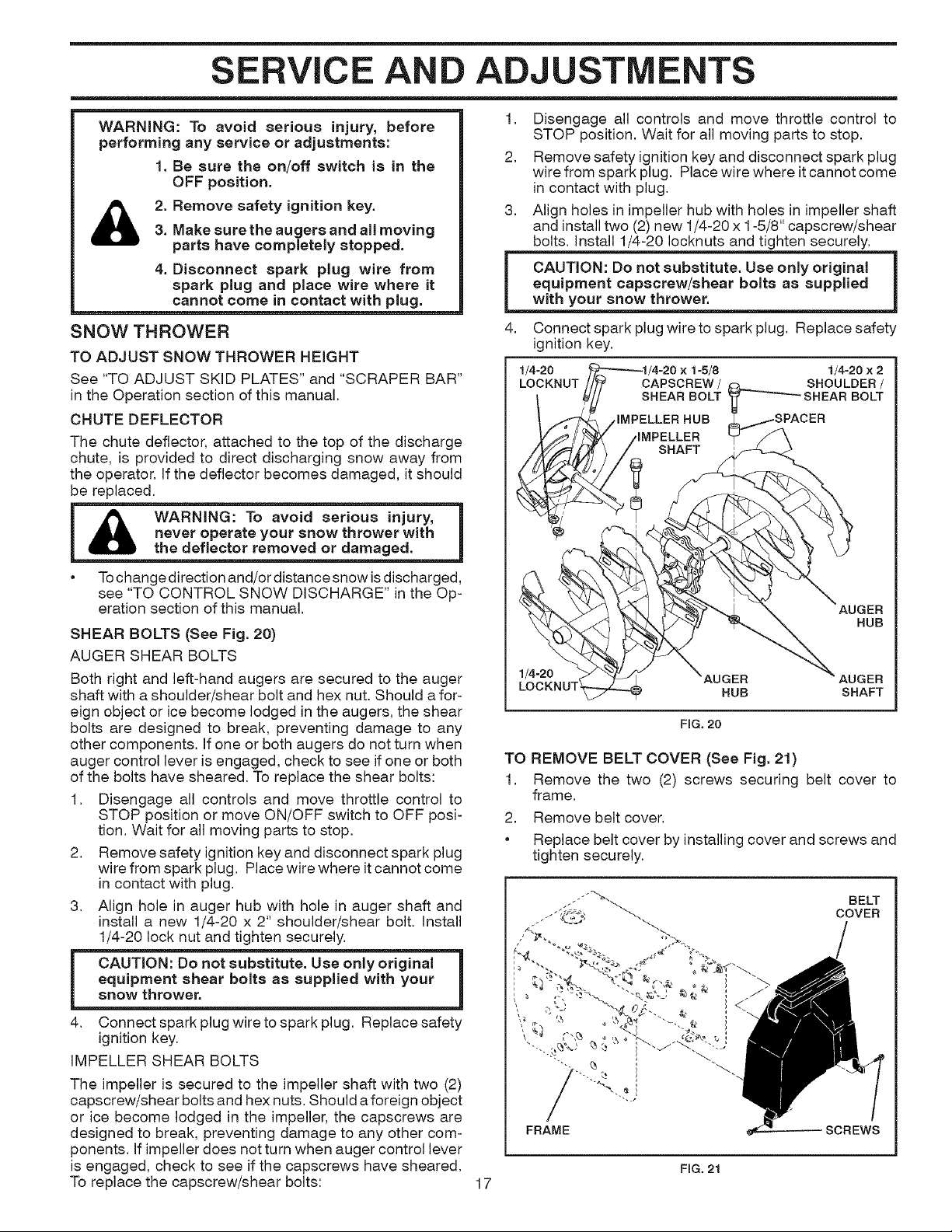
SHEAR BOLTS (See Fig. 20)
AUGER SHEAR BOLTS
Both right and left-hand augers are secured to the auger
shaft with a shoulder/shear bolt and hex nut. Should a for-
eign object or ice become lodged in the augers, the shear
bolts are designed to break, preventing damage to any
other components. If one or both augers do not turn when
auger control lever is engaged, check to see if one or both
of the bolts have sheared. To replace the shear bolts:
1. Disengage all controls and move throttle control to
STOP position or move ON/OFF switch to OFF posi-
tion. Wait for all moving parts to stop.
2. Remove safety ignition key and disconnect spark plug
wire from spark plug. Place wire where it cannot come
in contact with plug.
3. Align hole in auger hub with hole in auger shaft and
install a new 1/4-20 x 2" shoulder/shear bolt. Install
1/4-20 lock nut and tighten securely.
CAUTION: Do not substitute. Use only original
equipment shear bolts as supplied with your
snow thrower.
4. Connect spark plug wire to spark plug. Replace safety
ignition key.
IMPELLER SHEAR BOLTS
The impeller is secured to the impeller shaft with two (2)
capscrew/shear bolts and hex nuts. Should a foreign object
or ice become lodged in the impeller, the capscrews are
designed to break, preventing damage to any other com-
ponents. If impeller does not turn when auger control lever
is engaged, check to see if the capscrews have sheared.
To replace the capscrew/shear bolts:
FIG, 20
TO REMOVE BELT COVER (See Fig. 21)
1. Remove the two (2) screws securing belt cover to
frame.
2. Remove belt cover.
• Replace belt cover by installing cover and screws and
tighten securely.
FIG, 21
17
SERVICE ADJUSTMENTS
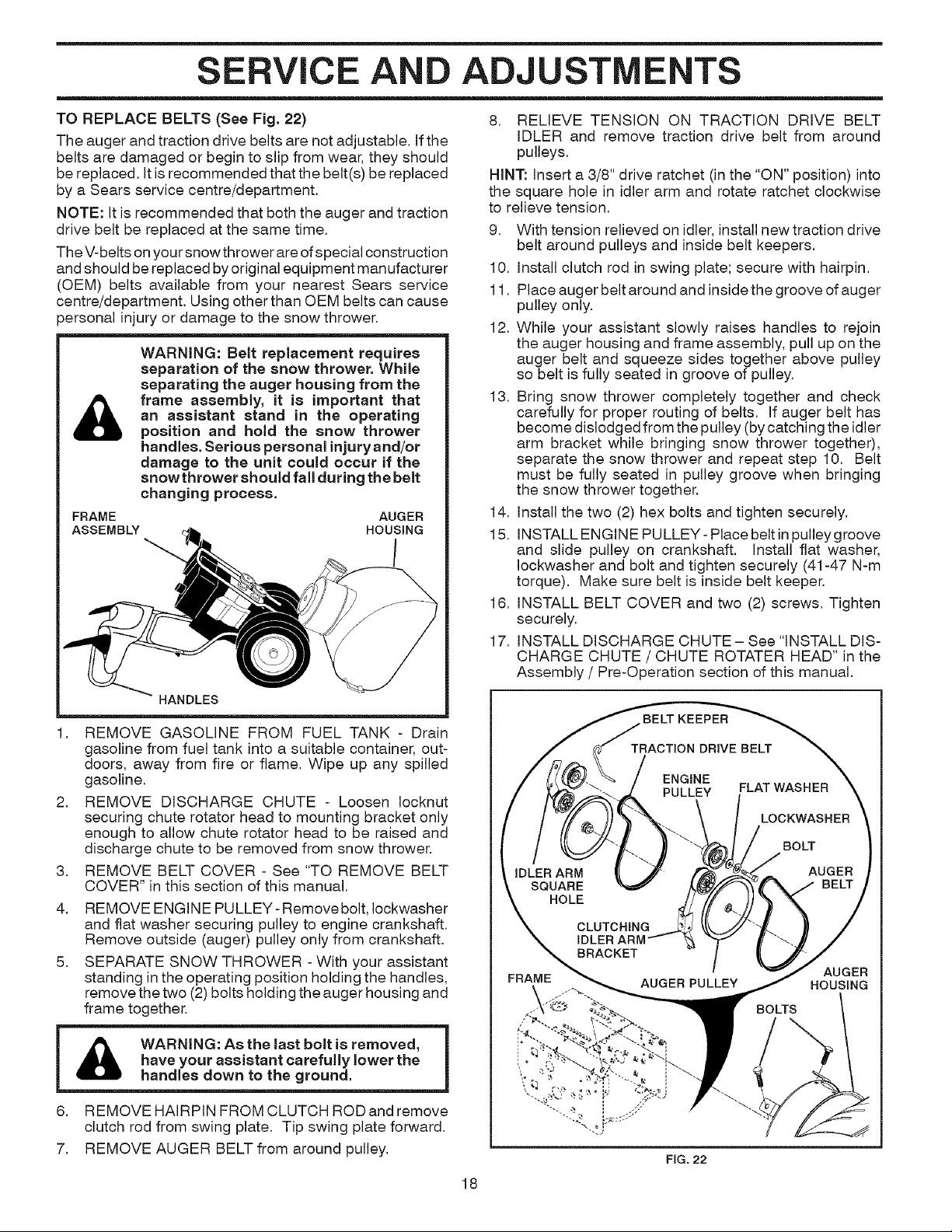
TO REPLACE BELTS (See Fig. 22)
The auger and traction drive belts are not adjustable. If the
belts are damaged or begin to slip from wear, they should
be replaced. It is recommended that the belt(s) be replaced
by a Sears service centre/department.
NOTE: It is recommended that both the auger and traction
drive belt be replaced at the same time.
The V-belts on your snow thrower are of special construction
and should be replaced byoriginal equipment manufacturer
(OEM) belts available from your nearest Sears service
centre/department. Using other than OEM belts can cause
_ersonal injury or damage to the snow thrower.
WARNING: Belt replacement requires
separation of the snow thrower, While
separating the auger housing from the
frame assembly, it is important that
an assistant stand in the operating
position and hold the snow thrower
handles, Serious personal injury and/or
damage to the unit could occur if the
snow thrower should fall during the belt
changing process.
FRAME AUGER
ASSEMBLY HOUSING
8. RELIEVE TENSION ON TRACTION DRIVE BELT
IDLER and remove traction drive belt from around
pulleys.
HINT: Insert a 3/8" drive ratchet (in the "ON" position) into
the square hole in idler arm and rotate ratchet clockwise
to relieve tension.
9. With tension relieved on idler, install new traction drive
belt around pulleys and inside belt keepers.
10. Install clutch rod in swing plate; secure with hairpin.
11. Place auger belt around and inside the groove of auger
pulley only.
12. While your assistant slowly raises handles to rejoin
the auger housing and frame assembly, pull up on the
auger belt and squeeze sides together above pulley
so belt is fully seated in groove of pulley.
13. Bring snow thrower completely together and check
carefully for proper routing of belts. If auger belt has
become dislodged from the pulley (by catching the idler
arm bracket while bringing snow thrower together),
separate the snow thrower and repeat step 10. Belt
must be fully seated in pulley groove when bringing
the snow thrower together.
14. Install the two (2) hex bolts and tighten securely.
15. INSTALL ENGINE PULLEY- Place belt inpulley groove
and slide pulley on crankshaft. Install flat washer,
Iockwasher and bolt and tighten securely (41-47 N-m
torque). Make sure belt is inside belt keeper.
16. INSTALL BELT COVER and two (2) screws. Tighten
securely.
17. INSTALL DISCHARGE CHUTE - See "INSTALL DIS-
CHARGE CHUTE / CHUTE ROTATER HEAD" in the
Assembly / Pre-Operation section of this manual.
1, REMOVE GASOLINE FROM FUEL TANK - Drain
gasoline from fuel tank into a suitable container, out-
doors, away from fire or flame, Wipe up any spilled
gasoline,
2, REMOVE DISCHARGE CHUTE - Loosen Iocknut
securing chute rotator head to mounting bracket only
enough to allow chute rotator head to be raised and
discharge chute to be removed from snow thrower,
3, REMOVE BELT COVER - See "TO REMOVE BELT
COVER" in this section of this manual,
4. REMOVE ENGINE PULLEY-Removebolt, lockwasher
and flat washer securing pulley to engine crankshaft,
Remove outside (auger) pulley only from crankshaft,
5, SEPARATE SNOW THROWER - With your assistant
standing in the operating position holding the handles,
remove the two (2) bolts holding the auger housing and
frame together,
I WARNING: As the last bolt is removed,
I have your assistant carefully lower the I
&
handles down to the ground.
6. REMOVE HAIRPIN FROM CLUTCH ROD and remove
clutch rod from swing plate. Tip swing plate forward.
7. REMOVE AUGER BELT from around pulley.
HOLE
FRAME ROUSING
m
FIG. 22
18
AUGER
 Loading...