

Page 1

Owner’s Manual
5.5 HORSEPOWER 22 INCH CUT
WHEELED
WEEDTRIMMER
Model No.
917.773423
Safety
Assembly
Operation
Maintenance
Español
Repair Parts
^CAUTION:
Read and follow all
Safety Rules and Instructions
before operating this equipment
Sears, Roebuck and Co., Hoffman Estates, IL 60179
Visit our Craftsman website: www.sears.com/craftsman
Page 2

TABLE OF CONTENTS
Warranty
Safety Rules
Assembly
Operation
Maintenance Schedule.................
Maintenance...............................
....................................
...............................
...................................
...................................
...............
............
...............
............
...............
..........
9-12
2
Product Specifications..............
2-4
Service and Adjustments....
5
Storage..................................
6-8
Troubleshooting
9
Repair Parts
Parts Ordering
...........................
......................
........................
WARRANTY
LIMITED TWO YEAR WARRANTY ON CRAFTSMAN WEEDTRIMMER
For two years from date of purchase, when this Craftsman Weedtrimmer is maintained,
lubricated, and tuned up according to the operating and maintenance instructions in
the owner’s manual, Sears wili repair free of charge any defect in material or workman
ship.
If this Craftsman Weedtrimmer is used for commercial or rental purposes, this warranty
applies for only 90 days from the date of purchase.
This Warranty does not cover:
’ Expendabie items which become worn during normal use, such as rotating iines,
belts, air cleaners and spark plug.
• Repairs necessary because of operator abuse or negiigence, including bent
crankshafts and the failure to maintain the equipment according to the instructions
contained In the owner's manual.
Warranty serwce is available by returning the Craftsman Weedtrimmer to the nearest
Sears Service Center in the United States. This warranty applies only while this product
Is in use in the United States.
This Warranty gives you specific legal rights, and you may also have other rights which
vary from stale to state.
Sears, Roebuck and Co., Dept. 817 WA, Hoffman Estates, IL 60179
...................
............
13-14
.................
.................
............
34-41
....Back Cover
9
15
16
WARNING: This trimmer is equipped with an internal combustion engine and should
not be used on or near any unimproved forest-covered, brush-covered or grasscovered land unless the engine’s exhaust system is equipped with a spark arrester
meeting applicable local or state laws (if any). If a spark arrester is used, it should be
maintained in effective working order by the operator.
In the state of California the above is required by law (Section 4442 of the California
Public Resources Code). Other states may have similar laws. Federal laws apply on
federal lands. A spark arrester for the muffler is available through your nearest Sears
service center (See REPAIR PARTS section of this manual).
Page 3

SAFETY RULES
The operation of any trimmer can result in foreign objects thrown into
the eyes, which can result in severe eye damage. Always wear safety
glasses or eye shields while operating your trimmer or performing any
adjustments or repairs. We recommend a wide vision safety masK
over spectacles or standard safety glasses.
1^
I. GENERAL OPERATION
• Read, understand, and follow ail
instructions on the machine and in the
manual before starting. Be thoroughly
familiar with the controls and the proper
use of the machine before starting.
• Do not put hands or feet near or under
rotating parts.
• Keep all parts of your body away from
muffler and spinning line. A hot muffler
can cause serious bums.
• Only allow responsible individuals, who
are familiar with the instructions, to
operate the machine.
• Stay away from breakable objects, such
as house windows, auto glass, green
houses, etc.
• Clear the area of objects such as rocks,
toys, wire, bones, sticks, etc., which
could be picked up and thrown by the
spinning lines.
• Be sure the area is clear of other
people before trimming, particularly
small children and pets. Stop machine
if anyone enters the area.
• Wear appropriate clothing such as a
long-sleeved shirt or jacket. Also wear
long trousers or slacks. Do not wear
shorts.
• Do not wear loose clothing which could
get caught in this equipment.
• Do not operate the machine when
barefoot or wearing open sandals.
Always wear work gloves and sturdy
footwear. Leather work shoes or short
boots work well for most people. These
will protect the operator’s ankles and
shins from small sticks, splinters, and
other debris, and improve traction.
• Do not pull machine backwards unless
absolutely necessary. Always look
dcvm and behind before and while
moving backwards.
Do not operate the machine without
proper guards, plates or other safety
protective devices in place.
See manufacturer’s instructions for
proper operation and installation of
accessories. Only use accessories
approved by the manufacturer.
Never use blades, wire, or flailing
devices. This unit is designed for line
trimmer use only. Use of other accesso
ries or attachments will increase the risk
of injury.
Stop the rotating trimmer head when
crossing gravel drives, walks, or roads.
Wait for the cutting lines to stop rotating.
Stop the engine (motor) whenever you
leave the equipment and allow it to
cool, before cleaning, repairing or
Inspecting the unit. Be sure the trimmer
head and all moving parts have
stopped.
Operate only in daylight or good
artificial light.
Do not operate the machine while
under the influence of alcohol or drugs.
Never operate machine in wet grass.
Always be sure of your footing: keep a
firm hold on the handle and walk; never
run.
If the equipment should start to vibrate
abnormally, stop the engine (motor)
and check immediately for the cause.
Vibraflon is generally a warning of
trouble.
Always wear safety goggles or safety
glasses with side shields when operat
ing machine.
Page 4

II. SLOPE OPERATION
Slopes are a major factor related to slip
and fall accidents which can result in
severe Injury. All slopes require extra
caution. If you feel uneasy on a slope, do
not trim it.
DO:
■ Trim across the face of slopes: never up
and down. Exercise extreme caution
^Ari1en changing direction on slopes.
• Remove obstacles such as rocks, tree
limbs, etc.
• Watch for holes, ruts, or bumps. Tall
grass can hide obstacles.
DO NOT:
• Do not trim near drop-offs, ditches or
embankments. The operator could lose
footing or balance.
• Do not trim excessively steep slopes.
• Do not trim on wet grass. Reduced
footing could cause slipping.
III. CHILDREN
Tragic accidents can occur if the operator
is not alert to the presence of children.
Children are often attracted to the machine
and the trimming activity. Never assume
that children will remain where you last
saw them.
• Keep children out of the trimming area
and under the watchful care of another
responsible adult.
• Be alert and turn machine off if children
enter the area.
• Before and while moving backwards,
look behind and down for small
children.
• Never allow children to operate the
machine.
• Use extra care when approaching blind
comers, shrubs, trees, or other objects
that may obscure vision.
IV. SERVICE
• Use extra care in handling gasoline
and other fuels. They are flammable
and vapors are explosive.
- Use only an approved container.
- Never remove gas cap or add fuel
with the engine running. Allow
engine to cool before refueling. Do
not smoke.
- Never refuel the machine indoors.
- Never store the machine or fuel
container inside where there is an
open flame, such as a water heater.
- Move away from fueling site before
starting engine.
• Never run a machine inside a closed
area.
• Never make adjustments or repairs
with the engine (motor) running.
Disconnect the spark plug wire, and
keep the vwre away from the plug to
prevent accidental starting.
• Keep nuts and bolts, especially trimmer
head and engine bolts, light and keep
equipment in good condition.
• Never tamper with safety devices.
Check their proper operation regularly,
• Keep machine free of grass, leaves, or
other debris buildup. Clean oil or fuel
spillage. Allow machine to cool before
cleaning or storing.
• Stop and inspect the equipment if you
strike an object. Repair, if necessary,
before restarting.
• Do not change the engine governor
setting or overspeed the engine.
• Clean and replace safety and instruc
tion decals as necessary.
ALook for this symbol to point out
important safety precautions. It means
CAUTIONIII BECOME ALERTMI YOUR
SAFETY IS INVOLVED.
A WARNING: In order to prevent
accidental starting when setting up,
transporting, adjusting or making repairs,
always disconnect spark plug wire and
place wire where it cannot contact spark
plug.
A CAUTION: Muffler and other engine
parts become extremely hot during
operation and remain hot after engine
has stopped. To avoid severe burns on
contact, stay away from these areas.
Page 5
ASSEMBLY
Read these instmctions and this tnanual in its
entirety before you attempt to assemble or
opierate your new trimmer,
IMPORTANT; This trimmer is shipped
WITHOUT OIL OR GASOUNE in the engine.
Your new trimmer has been assetrtded at the
factory with the exception of those parts left
unassembled for shipping purposes. Al parts
such as nuts, washers, bolts, etc., necessary
to complete the assembly have been placed
in the parts bag. To ensue safe and proper
operation of your triemer, all parts and
hardware you assemble must be tightened
searety. Use the oorrect tools as necessary
to ensue proper tightness.
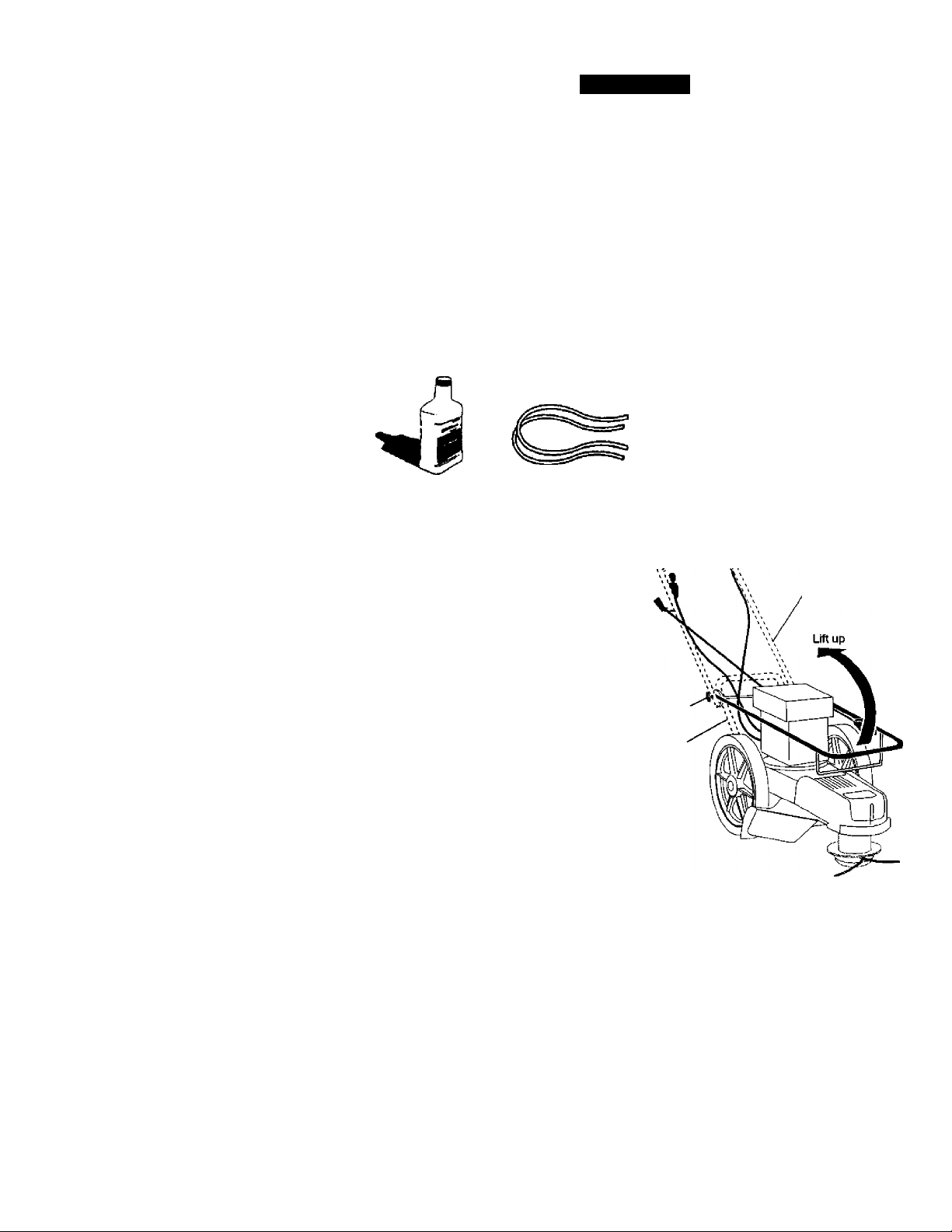
Loose Parts Packed Separately
20 oz.
Battle of oil
Trimmer Lines
(2)Sets
{0.155 dla mater
X 1S.7S Inches long)
TO REMOVETRIMMER FROM CARTON
1. Remove loose parts included with
trimmer.
2. Cut down two end comers of carton
and lay end panel down flat.
3. Remove all packing materials.
4. Roll trimmer out of carton and check
carton thoroughly for additional loose
parts.
HOWTO SET UPVOURTRIMMER
TO UNFOLD HANDLE
IMPORTANT: Unfold handle carefuly so as
not to pinch or damage control cables.
1. Loosen handle knob enough to allow
upper handle to be unfolded from the
shipping position.
2. Raise upper handle section into place
on lower handle and tighten handle
knob.
3. Remove handle padding holding
trimmer head control bar to upper
handle.
Your trimmer handle can be adjusted for
your trimming comfort. Refer to "ADJUST
HANDLE" in the Service and Adjustments
section of this manual.
Handle
knob
Lower
handle
Upper handle
Page 6

OPERATION
KNOW YOUR TRIMMER
READ THIS OWNER'S MANUAL AND SAFETY RULES BEFORE OPERATING YOUR
TRIMMER. Compare the Ikistrations with your trimmer to famiiarize yourself with the location
of various controls and adjustments. Save this manual for future reference.
TtMse tymbols may appear on your trimmer or In llBtalura suppled wMh the product Loam and undeistand
their meaning.
___________________
A WARNING
*V0HI SERIOUS BUUBYflR ffiJtTH
■ RtAUANDFOLLOVJO'.VNER'S
[1 MAhUAL.
ill LEA YS'GALL MANUAL DCL
il PROPIETARm.
00 NOT OPE RATE WHEN CHIIDHFN
OR OTFLKS AML AROUND HlF/OUL
DBJEITS ThAUOUlDBETHFtOa'IJ
BVTHI CUniNGLIMS
I
OQ UCT SERU CE DR ADJUST CUriNG
HEAD DR OTHER MOUirJO PARTS
UNLESS ENGITJE IS STOPPED AND
SPARK PLUG WIRE IS DISCONNECTED.
I
■ WEAR SAFETY APPRO'JED EYE
>1 PROTECTION WHtlJ DPtRAl NG
GO ACROSS SLOPES NOT UP AND
DOWN.
• KEEP SAFETY DEUJCES SUCH AS GUARDS AfiD
OEFLECTOHS II! PLACE AND OPERATING
- LOCK oov;n and abiimo before and ivnile
MOVING 6ACKVJARDS.
ÌA
CALinOh
4»
(i
FUEL OIL
Throttle control
starter handle
Handle knob
Engine oil cap w/dipstick
IMPORTANT; This trimmer is shipped
WITHOUT OIL OR GASOUNE in the engine.
Trimmer head control bar - must be held
down to the handle to engage trimmer head.
Release to stop the trimmer head.
Primer - pumps additional fuel from the
carburetor to the cylinder for use when
starting a cold engine.
Trimmer head control bar
Gasoline cap
Engine cover
Primer
Chassis cover
Trimmer head
Trimmer line
Throttle control - used tor starting artd
stopping the engine and alows you to select
^ther fast or stow engine speed.
Starter handle - used tor starting the engirve.
6
Page 7

The operation of any trimmer can result in
foreign objects being thrown into the
eyes, which can result in severe eye
damage. Always wear safety glasses or
eye shields while operating your trimmer
or performing any adjustments or repairs.
We recommend a wide vision safety mask
over spectacles or standard safety
glasses.
HOWTO USEYOURTRIMMER
ENGINE SPEED
The engine speed is controlled by a
throttle located on the side of the upper
handle. Fast position is for starting and
normal trimming. Slow is for light trimming
and fuel economy. Stop is for stopping the
engine.
TO ADJUST TRIMMING HEIGHT
ACAUTION: Stop the engine and wait
for alt moving parts to stop. Disconnect
spark plug wire from spade plug and
place wire where it cannot come in
contact with plug.
The height of cut can be set to six (6)
different positions ranging from 1-1/2
inches to 3 Inches. Recommended cutting
height for the average yard is 2 inches.
1. To adjust trimming height, push in the
locking plate tab and move trimmer
head up or down to desired position.
2. Release lab and be sure head is
locked into one of the six (6) height
positions.
Adjustable
Trimmer
Head
Locking
Plate Tab
TRIMMER HEAD DRIVE CONTROL
Your trimmer is equipped with a trimmer
head drive control bar which will require
the operator to be positioned behind the
trimmer handle to operate the trimmer.
• Trimmer head rotation is controlled by
holding the trimmer head control bar
down to the handle.
• Trimmer head rotation will stop when
the control bar is released.
BEFORE STARTING EN^NE
ADD OIL
Your trimmer is shipped without oil in the
engine. For type and grade of oil to use,
see “ENGINE" in the Maintenance section
of this manual.
A CAUTION; DO NOT overfill engine with
oil, or it will smoke on startup.
1. Be sure trimmer is level and area
around oil fill is clean.
2. Remove oil dipstick from oil fill spout.
Make sure that rim of spout is clean.
Page 8
3. You receive a 20 oz. container of oii
with the unit. Slowly pour 3/4 (15 oz.)
of the oil from the container down the
oii fili spout into the engine.
4. Wait one minute to allow oil to settle.
Insert and tighten dipstick, then
remove it to check oil level.
5. Continue adding small amounts of oil
and recheckIng the dipstick until it
reads full. DO NOT overfill, or engine
will smoke on startup.
6. Always be sure to retighten oil dipstick
before starting engine.
• Check oil level before each use. Add oil if
needed. Fit to fiil ine on dipstick.
• Change the oi after every 25 hours of
operation or each season. You may need
to change the oil more often under dusty,
dirty conditions.
ADD GASOUNE
• Fil fuel tank. Use fresh, dean, regular
unleaded gasoine with a minimum of 87
octane. Do not mix oil with gasoSne.
Pirchase fuel in quantities that can be
used within 30 days to assure fuel
freshness.
^WARNING: Experience indicates that
alcohol blended fuels (called gasohol or
using ethanol or methanol) can attract
moisture which leads to separation and
formation of adds during storage. Acidic
gas can damage the fuel system of an
engine while in storage. To avoid engine
problems, the fuel system should be
emptied before storage of 30 days or
longer. Drain the gas tank, start the
engine and let it run until the fuel lines
and carburetor are empty. Use fresh fuel
next season. See Storage Instructions for
additional infonuation. Never use engine
or carburetor cleaner products in the fuel
tank or permanent damage may occur.
A CAUTION: Fill to bottom of gas tank
filler neck. Do not overfill. Wipe off any
spilled oil or fuel. Do not store, spill or
use gasoline near an open flame.
TO START ENGINE
1. To start a cold engine, push primer three
(3) tines before trying to start Useaftm
push. This step is not usually necessary
when starling an engine which has
aieady mn ibr a few minutes.
2. Move throttle control lever to fast position.
3. Hold upper handle firmly and pul starter
handle quickly. Do not allow starter rope
to snap back.
TO STOP ENGINE
• To stop engiie, move throttle control lever
to stop position.
NOTE: In cooler weather it may be
necessary to repeat priming steps. In
warmer weather overpriming may cause
flooding and engine will not start. If you
do flood engine, wait a few minutes
before attempting to start and do not
repeat priming steps.
Throttle
control
Starter
handle
TRIMMING TIPS
• Set the throttle control in the fast
position. If the weeds or grass are tall
and thick, operate the trimmer at a
slower walking speed.
• Frequently clean the underside of the
trimmer to remove any grass build up.
Keep top of engine around starter dear
and dean of grass dippings and chaff.
This will help engine air flow and extend
engine life. See "TO REMOVE ENGINE
COVER” in the Maintenance section of
this manual.
• For best results and longer lasting line,
use the ends of the line to do the cutting.
This is easily done by moving slowly
through very thick and heavy weeds.
• Use the left side of trimmer when
trimming along fences, wails, flowerbeds
and other such cfojects,
• If bimmer lines become too short, it will
take longer to complete the jcfo, tf
trimmer lines are worn to less than half
their original length, they should be
replaced. See “TO REPLACE TRIMMER
LINE" in the Maintenance section of this
manual.
• Trimmer head contact with concrete,
asphalt or other hard surfaces may
cause premature wear of the ball on .
bottom of trimmer head.
8
Page 9

MAINTENANCE SCHEDULE
FILL IN DATES
AS YOU COMPLETE
MAINTENANCE
Check for Loose Fasteners
Clean Trimmer
Clean Under Engine Cover
Check drive be№pulleys
Check/Replace Trimmer Lines
Check Engine Oil Level
Change Engine Oil
Clean Air Filter
inspect Muffler
Clean or Replace Spark Plug
Replace Air Filter Paper Cartridge
1 - Chang« more often whan oparaiino undar a haavy load or in high ambient temparaturas.
2 - Servica more often when operating in dirty or duafy condlbna.
S- Replace trimmer lines when they have worn to half their original length.
✓
✓
✓ 2 ✓
✓ s
✓
GENERAL RECOMMENDATIONS
The warranty on this trimmer does not
cover items that have been subjected to
operator abuse or negligence. To receive
full value from the warranty, operator must
maintain trimmer as instructed in this
manual.
Some adjustments will need to be made
periodicaHy to properly maintain your unit.
All adjustments in the Service and
Adjustments section of this manual should
be checked at least once each season.
• Once a year, replace the spark plug
and replace air filter element. A new
spark plug and clean/new air filter
element assures proper air-fuel mixture
and helps your engine run better and
last longer.
» Follow the maintenance schedule in
this manual.
BEFORE EACH USE
1. Check engine oil level.
2. Check for loose fasteners.
3. Clean under engine cover.
LUBRICATION
To probng the useful life of your trimmer,
change engine oil as recommended in
this section of Owner’s Manual.
✓
✓
✓
✓ 1.2
✓ 2
✓
✓
✓ 2
IMPORTANT; Do not ol or grease plastic
wheel bearings. Viscous lubricants will attract
dust and dirt that wil shorten the life of the
sdf- lubricating bearings. If you feel they must
be liAiricated, use only a dry, powdered
graphite type lubricant sparingly.
PRODUCT SPECIFICATIONS
Serial No.
_________________
_
Date of Purchase;
Gasoline 'IVpe: Unleaded Regular
Gasoline Capacity: 1.25 Quarts
Oii Type; SAE 30 (Above 32° F)
(API-SF-SJ) SAE 5W-30 (Below 32“F)
on Capacity: 20 Ozs.
Spark Plug : Champion RJ19LM4
(Gap: .045")
Trimmer Line Diameter: .155 inch
Trimmer Line Length: 18.75 inches
The model and serial numbers will be found on
a decal attached to the rear of the trimmer.
Record both serial number and date of
purchase in space provided above.
Page 10

TRIMMER
Always observe safety rules when perform
ing any maintenance.
TIRES
’ Keep tires Itee of gasoine, oil, or insect
control chemicals which can harm rubber.
• Avoid slumps, stones, deep ruts, sharp
objects and other hazards that may cause
tire damage.
TRIMMER UNE
For best results, replace trimmer lines
when they have worn to half their original
length. Use .155 inch diameter trimmer
line. Cut new trimmer line length to 18-3/4
inches. After new line is installed on
trimmer head, check all lines so they do
not vary more then one (1) inch in length.
This is important to make sure the trimmer
head is baianced and wili not vibrate
abnormally.
^WARNING: Use only the specified
trimmer line. Do not use other materials
such as wire, string, rope, etc. Wire can
break off during trimming and become a
dangerous missile that can cause serious
injury.
TO REPLACE TRiMMER LINE
1. Disconnect spark plug wire from spark
plug and place wire where it cannot
come in contact with spark plug.
Remove worn trimmer line from line
2.
carrier plate.
Fold new, cut to length, trimmer line in
3.
half and insert folded end through
carrier plate opening to back side of
retainer clip.
With folded end of line at back side of
retainer clip, pull line outward until
line is fully seated under the retainer
clip.
Repeat on other side of carrier plate.
Check all lines to be sure they are the
same length.
Reconnect spark plug wire to spark
plug.
Trimmer
line
earner plate
opening
Retainer
clip
ENGINE
LUBRICATION
Use only high quality detergent oil rated
with API service classification SF-SJ.
Select the oil's SAE viscosity grade
according to your expected operating
temperature.
_______________________
SAE VISCOSITY GRADES
yf 40*
TEMPERATURE RAJ40E ANTtOPATED BEFORE NEXT OL CHANGE
NOTE: Although multi-viscosity oils
(5W30, 10W30 etc.) improve starting in
cold weather, these multi-viscosity oils
will result in increased oil consumption
when used above 32° F. Check your
engine oil level more frequently to avoid
possible engine damage from running
low on oil.
Change the oil after every 25 hours of
operation or at least once a year if the
unit is not used for 25 hours in one year.
Check the crankcase oil level before
starting the engine and after each five (5)
hours of continuous use. Tighten oil plug
securely each time you check the oil
level.
10
Page 11

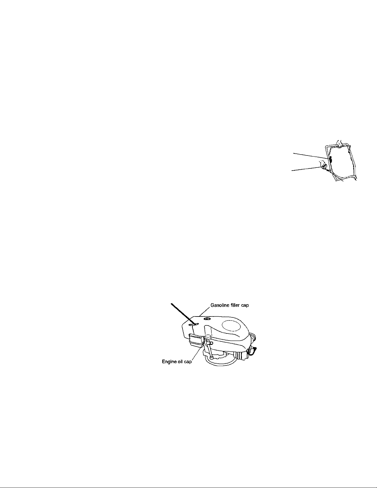
TO CHANGE ENGINE OIL
NOTE: Before tippirig trimmer to drain
oil, drain fuel tank by running engine
until fuel tank is empty.
1. Disconnect spark plug wire from spark
plug and (^ace wire where it cannot
come In contact with spark plug.
2. Remove engine oil cap; lay aside on a
dean surface.
3. Tip trimmer on its side as shown and
drain oil into a suitable container.
Rock trimmer back and forth to
remove any oil trapped inside of
engine.
4. Wipe off any spilled oil from trimmer
and side of engine.
5. Fill engine with oil (See "ADD OIL" In
the Operation section of this manual).
6. Replace engine oil cap.
7. Reconnect spark plug wire to spark
plug.
Container
AIR FILTER
Your engine will not run properly and may
be damaged by using a dirty air filter.
Replace the air filter every 100 hours of
operation or every season, whichever
occurs first. Service air cieaner more
often under dusty conditions. Do not
wash air filter.
TO CHANGE AIR FILTER
1. Remove the air filter by turning
clockwise to the stop and pull away
from collar.
2. Remove filter from inside of cover.
3. Clean the inside of the cover and the
collar to remove any dirt accumula
tion.
4. Insert new filter into cover.
5. Put air filter cover and filter into collar
aligning the tab with the slot.
6. Push in on cover and turn counter
clockwise to tighten.
Collar
clockwise
Air fiiter
Air filter cover
clockwise to tighten
counter
MUFFLER
Inspect and replace corroded muffler as
it could create a fire hazard and/or
damage.
SPARK PLUG
Replace spark plugs at the beginning of
each mowing season or after every 100
hours of operation, whichever occurs first.
Spark plug type and gap setting are
shown in “PRODUCT SPECIFICATIONS"
in Maintenance section of this manual.
CLEANING
IMPORTANT: For best performance,
keep trimmer free of built-up grass and
trash. Clean the underside of your
trimmer after each use.
^CAUTION: Disconnect spark plug wire
from spark plug and place wire where it
cannot come in contact with the spark
plug.
• Turn trimmer on its side. Make sure air
filter and carburetor are up. Clean the
underside of your trimmer by scraping
to remove build-up of grass and trash.
• Clean engine often to keep trash from
accumulafing. A clogged engine runs
hotter and shortens engine life.
• Keep finished surfaces and wheels
free of all gasoline, oil, etc.
• We do not recommend using a garden
hose to clean trimmer unless the
electrical system, muffler, air filter and
carburetor are covered to keep water
out. Water in engine can result in
shortened engine life.
11
Turn
to
remove
Turn
Page 12

CLEAN UNDER ENGINE COVER
Clean under engine cover before each
use, or more frequently in heavy cutting
or dirty conditions. Engine cover screen
and engine air intake screen must be
kept free of dirt and chaff to prevent
engine damage from overheating.
Be sure engine is cool before cleaning.
1. Unscrew knob on top of cover.
2. Lift cover up and away from engine.
Clean cover and cover screen
3.
thoroughly.
4.
Clean top of engine and air intake
screen.
5.
Replace engine cover and tighten
Imob securely. Be sure the front tabs
of engine cover are located in the
slots in engine housing.
12
Page 13

SERVICE AND ADJUSTMENTS
A CAUTION: Before performing any
service and adjustments:
1. Stop engine.
2. Make sure the rotating lines and all
moving parts have completely
stopped.
3. Disconnect spark plug wire from spark
plug and place where it cannot come
in contact with plug.
TRIMMER
TO ADJUST TRIMMING HEIGHT
See "TO ADJUSTTRIMMING HEIGHT' in the
Operation section of this manual.
TO ADJUST HANDLE
The upper handle may be adjusted to
different height positions.
• Loosen handle knob only enough to
allow the upper handle to pivot to the
desired position.
• Tighten handle knob securely.
NOTE: The handle knob and bolt may be
reversed for left handed operation.
Upper handle
TO REMOVE/REPLACE TRIMMER HEAD
DRIVE BELT
1. Remove screw at front of chassis
cover.
2. Lift cover up and away from trimmer.
Screw
3.
Remove the two (2) so'ews on sides
of trimmer securing the debris shield.
Turn trimmer on its side with carbure
4.
tor and fuel cap up.
5.
Remove the two (2) screws on
underside of trimmer securing the
debris shield.
6.
Slide the debris shield rearward and
remove.
7.
Remove belt from engine pulley on
crankshaft.
Debris shieid screws
13
Engine
pulley
Page 14

8. Remove belt from bimmer head pulley.
9. Note the position of the control cable
and idler return spring, then remove
idler assembly from chassis and
remove belt and idler from trimmer.
10. Remove bell from idler assembly by
removing bottom belt keeper and idler
pulleys.
11 .Assemble new belt, idler pulleys and
bottom belt keeper to idler bracket.
Tighten pulley bolts securely.
NOTE: Be sure belt is inside lop belt
keeper on idler assembly.
12.Position belt and idler assembly in
trimmer, reconnect idler spring and
assemble idler to chassis.
13.Install belt around trimmer head pulley
and engine pulley.
14. Replace debris shield and tighten the
four (4) screws securely.
15. Replace chassis cover and tighten
screw securely.
Always use Craftsman replacement parts
to assure proper fit and long life.
ENGINE SPEED
Your engine speed has been factory set.
Do not attempt to increase engine speed
or it may result in personal injury. If you
believe that the engine is running too fast
or too slow, take your unit to a Sears or
other qualified service center for repair
and/or adjustment.
CARBURETOR
Your carburetor has a nonadjustable fixed
main jet for mixture control. If your engine
does not operate properly due to sus
pected carburetor problems, lake your
unit to a Sears or other qualified service
center for repair and/or adjusbnent.
IMPORTANT: Never tamper with the
engine governor, which Is factory set for
proper engine speed. Overspeeding the
engine above the factory high speed
setting can be dangerous. If you think the
engine-governed high speed needs
adjusting, take your unit to a Sears or
other qualified service center, which has
proper equipment and experience to
make any necessary adjustments.
14
Page 15

STORAGE
Immediately prepare your trimmer for storage
at the end of the season or if the unit wll not
be used for 30 days or more.
TRIMMER
When trimmer is to be stored for a period of
time, dean it thoroughly, remove ail dirt,
grease, leaves, etc. Store in a dean, dry area.
1. Clean entire trimmer (See “Cl£ANING" in
the Maintenance section of this manuai).
2. Lubricate as shown in the Maintenance
section of this manual.
3. Be sure that all nuts, bdts, screws, arfo
pirrs are securely festened. Inspect
mowng parts for damage, breakage and
wear. Replace if necessary.
4. Touch up all rusted or chipped paint
surfooes; sarfo lightly before painting.
HANDLE
You can fold your trimmer handle for storage.
• Loosen hafole knob enough to alow
upper handte to be folded forward.
IMPORTANT: When folding the handle for
storage or transportation, be sure to fold the
handle as shown or you may damage the
control cables.
FUELSYSTEM
IMPORTANT: It is Important to prevent gum
deposits from forming in essential fuel system
parts such as carburetor, fuel titer, fuel hose or
tank during storage. Also, experience
irfoicates that alcohol blerfoed fuels (called
gasohol or using ethanol or methanol) can
attract moisture which leads to separation
and formation of adds during storage. Addk:
gas can damage the fuel system of an
engine whie in storage.
1. Drain the fuel tank.
2. Start the engine and let it run until the
fuel lines and carburetor are empty.
• Never use engine or carburetor cleaner
products in the fuel tank or permanent
damage may occur.
• Use fresh fuel next season.
NOTE: Fuel stabilizer is an acceptable
alternative in minimizing the formafion of fuel
gum deposits during storage. Add stabiizer
to gasoline in fuel tank or storage container.
Always fdbw the mix ratio found on stabPizer
contairrer. Run engine at least 10 minutes
after adding stabilizer to aPow the stabPizer to
reach the carburetor. Do not drain the gas
tank and carburetor if using fuel stabPi^.
ENGINE OIL
Drain oP (with engine warm) and replace with
dean engine oil. (See "ENGINE’ in the
Maintenance section of this manual).
CYUNDER
1. Remove spark plug.
2. Pour one ounce (29 ml) of oil through
spark plug hole into cylinder.
3. Pull starter handle slowly a few times
to distribute oil.
4. Replace with new spark plug.
OTHER
• Do not store gasoline from one season to
another.
• Replace your gasoline can if your can
starts to mst Rust and/or dirt in your
gasoline wPI cause problems.
• If possbie, stone your unit hdoors and
cover it to give protecBon from dust and dirt.
• Cover your unit with a suitable protective
cover that does not retain moisture. Do
not use plastic. Plastic cannot breathe,
which alows condensation to form and wPI
cause your unit to rust.
IMPORTANT: Never cover trimmer while
engirre and exhaust areas are stiU warm.
ACAUTION: Never store the trimmer
with gasoline in the tank inside a building
where fumes may reach an open flame or
spark. Allow the engine to cool before
storing in any enclosure.
15
Page 16

TROUBLESHOOTING
PROBLEM CAUSE
Does not start 1. Dirty air fitter.
2. Out of fuel.
3. Stale fuel.
4. Water in fuel,
5. Spark plug wire is
disconnected.
6. Bad spark plug.
7. Throttle control lever not
In correct position
(if equipped).
CORRECTION
1. Clean/replace air filter.
2. Fill fuel tank.
3. Drain tank and refill with
fresh clean fuel.
4. Drain fuel tank and
carburetor and refill tank
with fresh gasoline.
5. Connect wire to plug.
6. Replace spark plug.
7. Move throttle lever to FAST
position.
Loss of power 1. Dirty air filter.
2. Buildup of grass, leaves,
and trash under trimmer.
3. Too much oil in engine.
4. Walking speed too fast.
Excessive
Vibration
1. Lines uneven or broken.
2. Loose nuts or bolts.
3. Damaged trimmer head.
Starter rope hard
to pull
Loss of head
drive
Hard to push
1. Bent engine crankshaft. 1. Contact a Sears or other
1. Belt not driving. 1. Put belt on pulleys or
1. Handle height position not
right for you.
Poor trimming
performance
1. Trimmer line length is
too short.
2. Throttle control lever not
in correct position
(if equipped).
Trimmer head
does not
retain line
1. Trimmer line not
properiy installed.
2. Broken line retainer clip.
3. Incorrect size of
trimmer line.
1. Clean/replace air filter.
2. Clean underside of trimmer
and trimmer head.
3. Check oil level.
4. Trim at slower walking
speed.
1. Check trimmer lines.
2. Check all hardware,
Including engine bolts.
3. Check/repair trimmer head.
qualified service center.
replace belt if broken.
1. Adjust handle height
to suit.
1. If line is worn or broken to
half original length,
replace line.
2. Move throttle lever to FAST
position.
1. Follow instructions in
Maintenance section.
2. Replace string carrier plate
assembly.
3. Use .155 diameter
trimmer line.
16
Page 17

REPAIR PARTS
CRAFTSMAN WEED TRIMMER - MODEL NUMBER 917.773423
34
Page 18

CRAFTSMAN WEED TRIMMER-MODEL NUMBER917.773423
PART
KEY
NO.
NO.
1
150406
2
169791
3
STD502502
4
177622
5
174274
6
174030
7
169821X479
8
1S0078
9
169797X479
10
170980
11
136376
12
170681
13
170682
14
170554
15
153638
16
132004
17
66426
18
176983
19
174934
20
158755
21
178700X004
22
150078
23
52160
24
57143
25
752063
26
83923
27
176999
28
174034
29
174039
30
86899X004
34
750634
35
--
178779
Available accessories not Included with trimmer:
1133623 Gas Can {2.5 gal.)
7133000 SAE SOW Oil (20 oz.)
7179991 Trimmer Line (Pack of 24 strings, .155 dia.)
NOTE: All component dimensions given In U.S. inches
1 Inch = 25.4 mm
DESCRIPTION
Engine, Craitsman,
Model Number 143.015502
(See Breakdown)
Bolt, Engine Mounting 3/8-16
Pulley, Engine (Includes Setscrew, Key #4)
Setscrew, Pulley
Cover, Engine, with Screen
Knob, Engine Cover
Stud, Engine Cover
Handle, Lower
Screw, He* Washer Head 5/16-16 x.75
Handle, Upper
Bolt, Handle
Knob, Handle
Adjuster, Handle, Inside
Adjuster, Handle, Outside
Spring, Handle Adjust
Guide, Rope
Locknut 1/4 X 20
Wire Tiro
Control Bar
Throttle Control
Screw, Hex Washer Head
Axle Shaft Assembly
Screw, Hex Washer Head 5/16-18 x .75
Washer, Axle
Washer, Wave
Wheel, 14x2
Hex Flange Locknut 3/8-16
Drive Cable
Decal, Warning
Decal, Engine Cover
Bracket, Upstop
Screw, Thd. Rdl. #10-24 x 5/8
Owner's Manual, English/Spanlsh
35
Page 19

CRAFTSMAN WEED TRIMMER- - MODEL NUMBER917.773423
52 20 44 47 21
Page 20

CE^FTSMAN WEED TRIMMER - - MODEL NUMBER 917.773423
KEY PART
NO. NO. DESCRIPTION
174031X558
1
2 189802 Line, Trimmer . 155diameterx 18.75 long
3 173715 Screw, Self-Tapping 5/16-18x1
4 189790
5 172145X004 Bracket, Idler
6 166042
173716 Bolt, Hex Head 3/6-t6 x 1.25
7
e 751592
9 166043
10 160829
11 1S5552 Locknut 5/16-18
12 173717
13 174719 Bolt, Shoulder
14 145212
15 173811
16 177811
17 57808
18 85768 Screw #10-24 X 3/4
19 175301
20 170553
149746 Screw #10-24 X1-3/4
21
STD541137
22
STD551137 Washer, Lock 3/8
23
STD551037
24
169792 Pulley, Driven
25
26 172551 Spacer, Pulley
27 174549 Bearing
28 172520 Jackshaft
29 169766X479 Cover, Chassis, Bottom
174543 Spindle Housing /Assembly
30
31 174581 Ring, Retaining, External, 17mm
32 176973
33 172519 Locking Plate
34 174544 Carrier Plate Assembly
172516
36
37 174580 Ring, Retaining, Internal, 40mm
172523
38
39 172636 Bolt, Mow Ball
40 172342 Head Assembly, Complete
174029
41
43 174042 Decal, Instruction
44 174035
45 174596X479 Belt Keeper, Bottom
46 17060408
47 174036 Decal, Insbuctlon
48 62784 Washer
49 76399
50 59931 Locknut
51 177972
52 178848 Screw #10-16 X 5/8
NOTE: All component dimensions given In U.S. Inches
1 inch * 25.4 mm
Chassis Assembly
V-6elt
Pulley, Idler, V-Groove
Locknut, Hex 3/8-16
Pulley, Idler, Flat
Bdt, Shoulder
Spacer
Locknut, Flange
Spring, Return
Shield, Debris
Screw 1/4-20x1/2
Skin
Cover, Chassis, Top
Nut 3/8-24 UNF
Washer, Flat 3/8
(* Includes Upper Bearing, Key #27)
Spring, Locking Plate
Cover, Bearing
Mow Ball
(Includes Key Numbers 22-28, 30-39)
Spacer
Decal, Chassis Ctrver
Screw, Self-Tapping
Screw
Skirt
37
Page 21

CRAFTSMAN 4-CYCLE ENGINE MODEL NUMBER 143.015502
38
Page 22

CRAFTSMAN 4-CYCLE ENGINE
KEY PART KEY PART
NO. NO. DESCRIPTION NO. NO. DESCRIPTION
1 37266 Cylinder (Incl. 2,20 & 150) 169 36783 * Gasket, Valve Cover
2
26727 Dowel Pin
e 33734 6rea№erElement 174 30200
7 36557
12 36775 BreatherTube 179
12A 36558 BreatherCover&T ube (Incl. 12B) 162 6201 Screw, 1/4-28 X 7/8"
12B 36694 Breather Tube Elbow 184 26756
14 28277 Washer 185 36785 Intake Pipe
30569 Governor Rod (Incl. 14) 186 36255
15
34B39A Governor Lever 200 37134
16
31335
17
651018 Screw, T-15,8-32 X 19/64*
IS
37329 GovemorSprIng 209 30200
19
20 32600 Oil Seal
37459 Crankshaft 224 36786
30
40027
40
40028 Piston, Pin 8 Ring Set(.010*OS) 239 34336
40025 Piston & PinAssy,(Std.)(lnd.43) 241 36919
41
40026
42 40006 Ring Set (Std.) 260
40007 Ring Set (.010* OS)
43 20381
45 36777 Connecting Rod Assy. (Incl. 46)
46 32610A
48 27241
37460
50
29914 Oil Pump Ass'y. 292 26460
52
eg 37609 * Mounting Flange Gasket 298
70 37608 MountIngFlange 300
72 37614
75 27897
60 30574A
81 30590A Washer 309
30591
82
63 30588A GovemorSpool
86 650488 Screw, 1/4-20 X 1-1/4"
69 610961 Flywfteel Key 313 34080
90 611213 Rywheel
650815 Belleville Washer
92
93 650616
100 34443C
101 610118
103 651007
104 37480
110 37574
119 36787
120 36825 C^lnderHead goo
125 37288
126 37289
130 6021A Screw, 5/16-18x1-1/2"
135 37598 Resistor Spark Plug (RJ19LM4)
150 31672 Valve Spring
151 31673 Valve Spring Cap
151A 40017 Intake Valve Seal
Breather Ass'y. (tnd. 6 & 12A)
Governor LeverClamp
Piston, Pin & Ring Set (Std.)
Piston 4 Pin Ass'y, (.010* OS)
(Includes Key Number 43) 250 37122
Piston Pin Retaining Ring
Connecting Rod Bolt
Valve Lifter 285
Camshaft (Exhaust MCR)
(Includes Key Number 104) 290 34357
(Includes Key #72-83, 306)
Oil Drain Plug
Oil Seal
Governor Shaft
Governor Gear Ass'y. (Incl. 81) 309A 650783 Screw, 10-24 x 3/4"
Flywheel Nut 380
Solid State ignllon
Spark Plug Cover
Screw, T-15,10-24x15/16"
Cam Bushing
Ground Wire (Irtcludes Key # 417) (OpGonal)
' Cylinder Head Gasket 417 650821 Screw, 10-32 X 1/2" (Optional)
Exhaust Valve (Std.) (Incl. 151)
Intake Valve (Std.) (Incl. 151
172 36784
178 29752
30593
206
610973 Terminal
207
362006 Throttle Link
223 6S0451 Screw, 1/4-20 X 1"
236
650932
245 36905
36980
261 30200
262 650831
275
36790A
277
650988
35287A Starter Cup
287
650926 Screw, 8-32x21/64"
28763 Screw, 10-32 X 35/64"
35586
301
36246 Fuel Cap
305 35577
306
37610 ' ■0"-Ring
307 35499
650562 Screw, 10-32 X 3/8"
310
35578
37611
311A
36261 Lubrication Decal
370A
370C 37318 Primer Decal (3X)
640262 Carburetor (Incl. 184
390
590763
400
37613 Gasket Set
416
36085 Spark Arrestor Kit
7508376 Replacement Short Block
—
—
NOTE: All component dimensions given In U.S. Inches
1 inch
= 25.4 mm
MODEL NUMBER 143.015502
Valve Cover
Screw, 10-24 X 9/16"
Nut & Lock Washer, 1/4-28
Retainer Clip
* Gasket, Carburetor-Intake Pipe
Governor Link
Control Bracket (Incl. 206)
Screw, 10-24 X 9/16"
* Intake Pipe Gasket
Screw, 10-32 X 49/64"
• Air Cleaner Gasket
AIrCleaner Collar
Air Cleaner Filter
AIrCleaner Cover
Blower Housing
Screw, 10-24x9/16"
Screw, 1/4-20 X 1/2"
Muffler
Screw, 1/4-20 X 2-9/32"
Fuel Line
Fuel Line Clamp
Fuel Tank (Incl. 292 4 301)
Oil Fill Tube
"CT-Ring
Dipstick
Hold Down Bracket
Spacer
Rewind Starter
(Includes all Items Marked ')
750837B, order from 71-999
RPMHIgh 345010 3750
RPM Low 2000 to 2300
39
Page 23

CRAFTSMAN 4-CYCLE ENGINE
MODEL NUMBER 143.015502
PART
KEY
NO. DESCR1P1X>N
NO.
___
640262 Carburetor (Incl. 164 of Engine Parts List)
631615 Throttle Shaft & Lever Assembly
1
2 631767 Throttle Return Spring
4 631184
5 631183
6 640070
7 650506
16 631807 Fuel Fitting
17 651025
630766 Ter^lon Spring
18
20 640018
20A 640200
25 631867
27 631024
28 632019 Float
29 631028
30
631021
31 631022 Spring Clip
35 640259 Primer Bulb/Retalr№r Rlr>g
640080 Main Nozzle Tube
36
632766 CarburetorTube
36A
632547
37
40 640175 High Speed Bowl Nut
44 27110A
47 630748
48 631027
60 632760B Repair kit (Incl. items Marked *)
*
Dust Seal Washer
•
Dust Seal (Throttle)
*
Throttle Shutter
*
Shutter Screw
Throttle Crack Screw/ldle Speed Screw
Idle Restrictor Screw
Idle Restrictor Scrwe Cap (Slack)
Float Bowl
•
Float ShafI
*
Float Bowl "O’ Ring
*
Inlet Needle, Seat, & Clip (Incl. 31)
*
"O’ Ring, Main Nozzle Tube
*
Bowl Nut Washer
*
Welch Plug, Idle Mixture Well
*
Welch Plug, Atmospheric Vent
40
Page 24

CRAFTSMAN 4-CYCLE ENGINE
MODEL NUMBER 143.015502
KE¥
PART
NO.
NO. DESCRIPTION
_
__
S90763
590S99A
1
590600
2
590696
3
590601
4
590697
5
6 550698
590699
7
8 590700
11 S90764
590535
12
13 590701
— 5
O
------
2
0-'
Rewind Starter
Spring Pin (inci. 4)
Washer
Retainer
Washer
Brake Spring
Starter Dog
Dog Spring
Puiiey & Rewirrd Spring Ass'y.
Starter Housing Ass’y.
Starter Rope (Length 98" x 9/64" dia.)
Starter Hand ie
41
Page 25

■
Get it fixed, at your home or ours!
For repair of major brand appliances in your own
no matter who made it, no matter who sold iti
1-800-4-MY-HOME® Anytime, day or night
(1-800469^1663) (U.SA and Canada)
www.sear&com
For repair of carry-in products like vacuums, lawn equipment, and
electronics, call for the nearest Sears Parts and Repair Center.
1-800-488-1222 Anytime, day or night {U.S A onty)
www.sears.conn
www.sears.ca
m
m
that you need to do-it-yourself, call Sears PartsDlrect®“!
1-800-366-PART
(1-80CK366-7278)
wwwsears.com/partsdirect
6a.m.-11 pm, 7daysaweek
{US-Aoríy)
T0 purchase or inquire about a Sears Service Agreement
or Sears Maintenance Agreement
For the replacement parts, accessories and owner’s manuals
1-800-827-6655 (USA)
7 am. -5 p.m., CST, Mon. - Sat
Pata pedrset\tóo de reparación a
domicici, y pata ordenar piezas:
1-88SSIRHCX3AR^"
(1-888-7846427)
1-800-361-6665 (Canada)
9 am. -8 pm. EST, M - F, 4 p.m. Sal.
Au Canada pour service en fiant^
1-aOW.EfOYER“'
(1600-5386937)
HomeCentnal®
® Sears, Roebuck and Co.
® Registered Trademark /™ Trademark / Service Mark of Sears, Roebuck and Co.
® Marca Registrada I ™ Marca de Fábrica I Marca de Servicio de Sears, Roebuck and Co.
Marque de commerce / ^ Marque déposée de Sears, Roebuck and Co.
www.seats.ca
178779 02.22.01 BY
Printed in U.S.A.
 Loading...