

Page 1

Owner’s Manual
CRRFTSMRN
4.0 HORSEPOWER
20INCH CUT
WHEELED
WEEDTRIMMER
Mode! No.
917.773410
Safety
Assembly
Operation
Maintenance
Español
Repair Parts
^CAUTION:
Read and follow all
Safety Rules and Instructions
before operating this equipment.
Sears, Roebuck and Co., Hoffman Estates, IL60179
Visit our Craftsman website: www.sears.com/craftsman
Page 2

TABLE OF CONTENTS
Warranty
Safety Rules
Assembly
Operation
Maintenance
Maintenance
Schedule
2 Product Specifications i
2 Service and Adjustments 1:
5 Storage 1
6 Troubleshooting 11
9 Repair Parts 3(
9 Parts Ordering Back Cove
WARRANTY
LIMITED TWO YEAR WARRANTY ON CRAFTSMAN WEEDTRIMMER
For two years from date of purchase, when this Craftsman Weedtrimmer is maintained,
lubricated, and tuned up according to the operating and maintenance instructions in
the owner’s manual, Sears will repair free of charge any defect in material or workman
ship.
If this Craftsman Weedtrimmer is used for commercial or rental purposes, this warranty
applies for only 90 days from the date of purchase.
This Warranty does not cover:
• Expendable items which become worn during normal use, such as rotating lines,
belts, air cleaners and spark plug.
• Repairs necessary because of operator abuse or negligence, including bent
crankshafts and the failure to maintain the equipment according to the instructions
contained in the owner’s manual.
Warranty service is available by returning the Craftsman Weedtrimmer to the nearest
Sears Service Center in the United States. This warranty applies only while this produc’
is in use in the United States.
This Warranty gives you specific legal rights, and you may also have other rights which
vary from state to state.
Sears, Roebuck and Co., Dept. 817 WA, Hoffman Estates, IL 60179
WARNING: This trimmer is equipped with an internal combustion engine and should
not be used on or near any unimproved forest-covered, brush-covered or grass-
covered land unless the engine’s exhaust system is equipped with a spark arrester
meeting applicable local or state laws (if any). If a spark arrester is used, it should be
maintained in effective working order by the operator.
In the state of California the above is required by law (Section 4442 of the California
Public Resources Code). Other states may have similar laws. Federal laws apply on
federal lands. A spark arrester for the muffler is available through your nearest
authorized service center/department (See REPAIR PARTS section of this manual).
Page 3

SAFETY RULES
The operation of any trimmer can result in foreign objects thrown into
the eyes, which can result in severe eye damage. Always wear safety
glasses or eye shields while operating your trimmer or performing any
adjustments or repairs. We recommend a wide vision safety mask
over spectacles or standard safety glasses. The safety goggles
provided with your trimmer may be worn over spectacles.
A
I. GENERAL OPERATION
• Read, understand, and follow all
instructions on the machine and in the
manual before starting. Be thoroughly
familiar with the controls and the proper
use of the machine before starting.
• Do not put hands or feet near or under
rotating parts.
• Keep all parts of your body away from
muffler and spinning line. A hot muffler
can cause serious burns.
• Only allow responsible individuals, who
are familiar with the instructions, to
operate the machine.
• Stay away from breakable objects, such
as house windows, auto glass, green
houses, etc.
• Clear the area of objects such as rocks,
toys, wire, bones, sticks, etc., which
could be picked up and thrown by the
spinning lines.
• Be sure the area is clear of other
people before trimming, particularly
small children and pets. Stop machine
if anyone enters the area.
• Wear appropriate clothing such as a
long-sleeved shirt or jacket. Also wear
long trousers or slacks. Do not wear
shorts.
• Do not wear loose clothing which could
get caught in this equipment.
• Do not operate the machine when
barefoot or wearing open sandals.
Always wear work gloves and sturdy
footwear. Leather work shoes or short
boots work well for most people. These
will protect the operator’s ankles and
shins from small sticks, splinters, and
other debris, and improve traction.
• Do not pull machine backwards unless
absolutely necessary. Always look
down and behind before and while
moving backwards.
Do not operate the machine without
proper guards, plates or other safety
protective devices in place.
See manufacturer’s instructions for
proper operation and installation of
accessories. Only use accessories
approved by the manufacturer.
Never use blades, wire, or flailing
devices. This unit is designed for line
trimmer use only. Use of other accesso
ries or attachments will increase the risk
of injury.
Stop the rotating trimmer head when
crossing gravel drives, walks, or roads.
Wait for the cutting lines to stop rotating.
Stop the engine (motor) whenever you
leave the equipment, before cleaning,
repairing or inspecting the unit. Be sure
the trimmer head and all moving parts
have stopped.
Operate only in daylight or good
artificial light.
Do not operate the machine while
under the influence of alcohol or drugs.
Never operate machine in wet grass.
Always be sure of your footing: keep a
firm hold on the handle and walk; never
run.
If the equipment should start to vibrate
abnormally, stop the engine (motor)
and check immediately for the cause.
Vibration is generally a warning of
trouble.
Always wear safety goggles or safety
glasses with side shields when operat
ing machine.
Page 4

A\
SAFETY RULES (CONT.)
II. SLOPE OPERATION
Slopes are a major factor related to slip
and fall accidents which can result in
severe injury. All slopes require extra
caution. If you feel uneasy on a slope, do
not trim it.
DO:
• Trim across the face of slopes: never up
and down. Exercise extreme caution
when changing direction on slopes.
• Remove obstacles such as rocks, tree
limbs, etc.
• Watch for holes, ruts, or bumps. Tall
grass can hide obstacles.
DO NOT:
• Do not trim near drop-offs, ditches or
embankments. The operator could lose
footing or balance.
• Do not trim excessively steep slopes.
• Do not trim on wet grass. Reduced
footing could cause slipping.
III. CHILDREN
Tragic accidents can occur if the operator
is not alert to the presence of children.
Children are often attracted to the machine
and the trimming activity. Never assume
that children will remain where you last
saw them.
• Keep children out of the trimming area
and under the watchful care of another
responsible adult.
• Be alert and turn machine off if children
enter the area.
• Before and while moving backwards,
look behind and down for small
children.
• Never allow children to operate the
machine.
• Use extra care when approaching blind
corners, shrubs, trees, or other objects
that may obscure vision.
A
IV. SERVICE
• Use extra care in handling gasoline
and other fuels. They are flammable
and vapors are explosive.
- Use only an approved container.
- Never remove gas cap or add fuel
with the engine running. Allow
engine to cool before refueling. Do
not smoke.
- Never refuel the machine indoors.
- Never store the machine or fuel
container inside where there is an
open flame, such as a water heater.
- Move away from fueling site before
starting engine.
• Never run a machine inside a closed
area.
• Never make adjustments or repairs
with the engine (motor) running.
Disconnect the spark plug wire, and
keep the wire away from the plug to
prevent accidental starting.
• Keep nuts and bolts, especially trimmer
head and engine bolts, tight and keep
equipment in good condition.
• Never tamper with safety devices.
Check their proper operation regularly.
• Keep machine free of grass, leaves, or
other debris buildup. Clean oil or fuel
spillage. Allow machine to cool before
storing.
• Stop and inspect the equipment if you
strike an object. Repair, if necessary,
before restarting.
• Do not change the engine governor
setting or overspeed the engine.
• Clean and replace safety and instruc
tion decals as necessary.
Atook for this symbol to point out impor
tant safety precautions. It means CAU
TION!!! BECOME AWARE!!! YOUR
SAFETY !S !NVOLVED.
AcaUTION: In order to prevent acci
dental starting when setting up, transport
ing, adjusting or making repairs, always
disconnect spark plug wire and place
wire where it cannot contact spark plug.
AwARNING: The engine exhaust from
this product contains chemicals known to
the State of California to cause cancer,
birth defects, or other reproductive harm.
Page 5
ASSEMBLY
Read these instructions and this manual in its
entirety before you attempt to assemble or
operate your new trimmer.
IMPORTANT: This trimmer is shipped
WITHOUT OIL OR GASOLINE in the engine.
Your new trimmer has been assembled at the
factory with the exception of those parts left
unassembled for shipping purposes. All parts
such as nuts, washers, bolts, etc., necessary
to complete the assembly have been placed
in the parts bag. To ensure safe and proper
operation of your trimmer, all parts and
hardware you assemble must be tightened
securely. Use the correct tools as necessary
to ensure proper tightness.
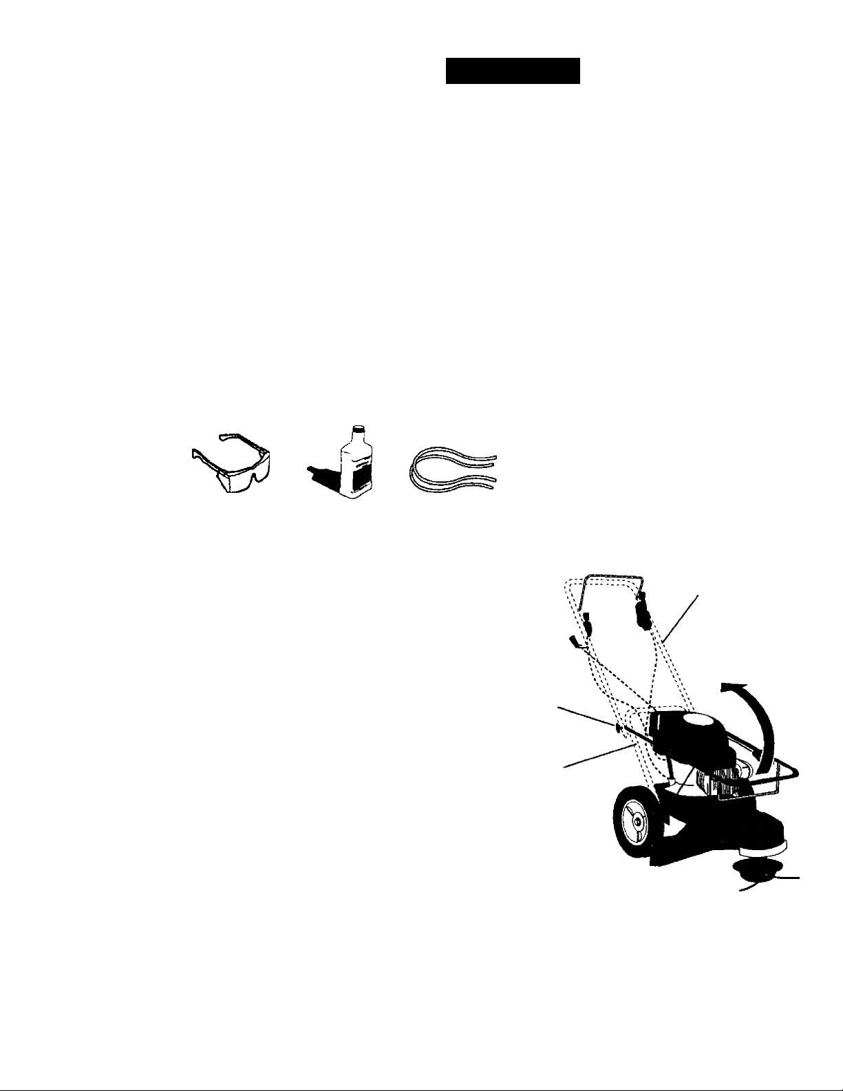
Loose Parts Packed Separately
TO REMOVE TRIMMER FROM CARTON
• Remove loose parts included with trimmer.
• Cut down two end comers of carton and
lay end panel down flat.
• Remove all packing materials.
• Roll trimmer out of carton and check carton
thoroughly for additional loose parts.
HOWTO SET UP YOUR TRIMMER
TO UNFOLD HANDLE
IMPORTANT: Unfold handle carefully so as
not to pinch or damage control cables.
• Loosen handle knobs enough to allow
upper handle to be unfolded from the
shipping position.
• Raise upper handle section into place on
lower handle and tighten handle knob.
• Remove handle padding holding trimmer
head control bar to upper handle.
Safety
Goggles
20 oz.
Bottle of oil
Trimmer Lines
(2) Sets
(0.130 diameter
X16.75 inches iong)
Upper handle
Lift up
Handle knob
Lower handle
Page 6
OPERATION
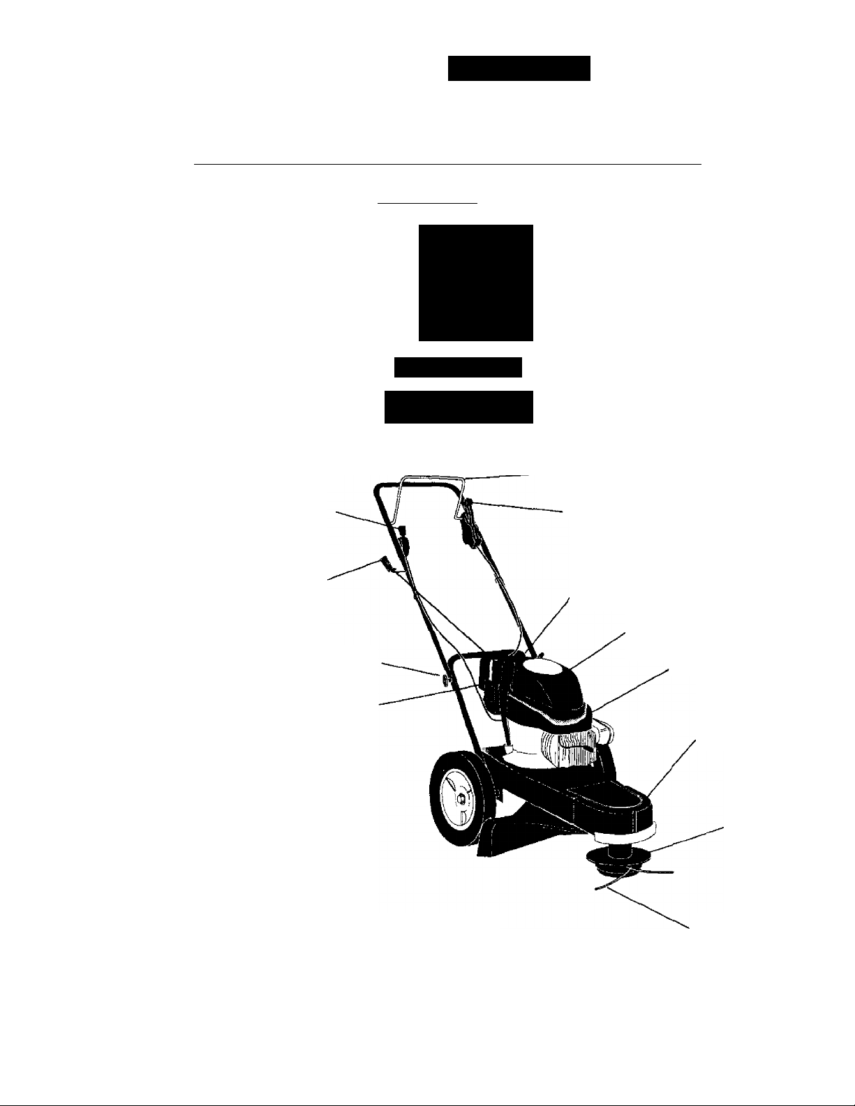
KNOW YOUR TRIMMER
READ THIS OWNER'S MANUALAND SAFETY RULES BEFORE OPERATING YOUR
TRIMMER. Compare the illustrations with your trimmer to familiarize yourself with the location
of various controls and adjustments. Save this manual for future reference.
These symbols may appear on your trimmer or in literature supplied with the product Learn and understarKi
their meaning. f A WARNING
Avno KMOUS mUlT OR DEATH
READ AND FOLLOW OWNER'S
manual.
UAYSIGA El MANUAL DEL
PROPIETARIQ.
00 NOTOPfHATi WHEN CHILDRfN
OROTHERSAftEAROUNO. REMOVE
OBJECTS TNAT COULD BF THROWN
BYTHECUrrrNGUHES.
DO NOT SERVICE OR ADJUST CUTTINC
HEAD OR OTHER MOVING PARTS
UNUSS ENCINT IS STOPPED AND
SPARK PLUG WIRE l£ DISCONNEnTD.
WEAR SAFETY APPHOVn) EYE
PROncnOH WHEN OPERATING.
¡SV GO ACROSS SLOPES NOT OP AND
iÇfl MWM
» KEEP SAFETY DEVICES, SUCH AS GUARDS AMO
DEFLECTORS. IN PLACE AND OPOIADNG.
> LOOK DOWN AND BEHIND BEFORE AND WHILE
MOVING BACKWARDS
(i 'Sr
Trimmer head control bar
Throttle control
Starter handle
Handle knob
Engine oil
cap w/
dipstick
Trimmer head control lever
Gasoline cap
Engine
cover
Primer
Chassis
cover
Trimmer head
IMPORTANT: This trimmer is shipped
WITHOUT OIL OR GASOLINE in the engine
Trimmer head control bar - must be held
down to the handle to engage trimmer head.
Release to stop the trimmer head.
Primer - pumps additional fuel from the
carburetor to the cylinder for use when
starting a cold engine.
Trimmer line
Throttle control - used for starting and
stopping the engine and allows you to select
either fast or slow engine speed.
Starter handle - used for starting the engine.
Trimmer head control lever - used to
engage trimmer head.
Page 7
WEAR YOUR
^ SAFETmASSES J
FORESIGHT IS BEHER
THAN NO SIGHT
The operation of any trimmer can result in
oreign objects thrown into the eyes,
/i/hich can result in severe eye damage.
Always wear safety glasses or eye shields
while operating your trimmer or perform
ing any adjustments or repairs. We
recommend a wide vision safety mask
over spectacles or standard safety
giasses. The safety goggles provided with
your trimmer may be worn over spec
tacles.
HOW TO USE YOUR TRIMMER
ENGINE SPEED
The engine speed is controlled by a
throttle located on the side of the upper
handle. Fast position is for starting and
normal trimming. Slow is for light trimming
and fuel economy. Stop is for stopping the
engine.
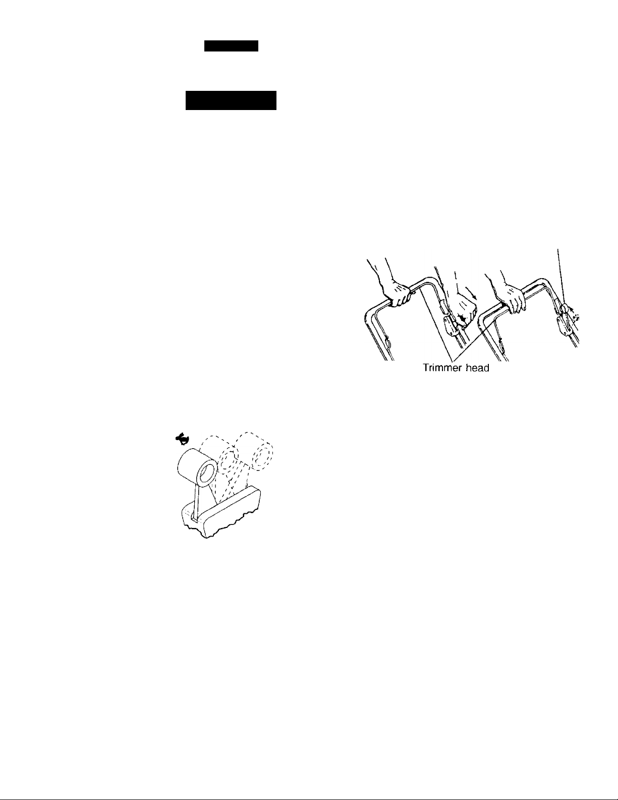
TRIMMER HEAD DRIVE CONTROL
Your trimmer is equipped with a trimmer
head drive control bar and lever which
requires the operator to be positioned
behind the trimmer handle to operate the
trimmer.
• Trimmer head rotation is controlled by
holding the trimmer head control bar
down to the handle and pushing the
drive control lever forward until it clicks;
then release the lever.
* Trimmer head rotation will stop when
the control bar is released.
Drive
control
lever
control bar
To engage
trimmer head
Trimmer head
disengaged
Page 8
BEFORE STARTING ENGINE ADD OIL
Your trimmer is shipped without oil in the
engine.
• Be sure trimmer is level and area around oil
fill is clean.
• Remove engine oil cap and fill to the full
line on the dipstick.
NOTE: Allow oil to settle down into engine
for accurate dipstick reading.
• Engine holds 20oz. of oil. For type and
grade of oil to use, see “ENGINE’ in
Maintenance section of this manual.
• Pour oil slowly. Do not over fill.
• Check oil level before each use. Add oil if
needed. Fill to full line on dipstick.
• To read proper level, tighten engine oil cap
each time.
• Reinstall engine oil cap and tighten.
• Change the oil after every 25 hours of
operation or each season. You may need
to change the oil more often under dusty,
dirty conditions.
ADD GASOLINE
• Fill fuel tank. Use fresh, clean, regular
unleaded gasoline with a minimum of 87
octane. Do not mix oil with gasoline.
Purchase fuel in quantities that can be used
within 30 days to assure fuel freshness.
^WARNING: Experience indicates that
alcohol blended fuels (called gasohol or
using ethanol or methanol) can attract
moisture which leads to separation and
formation of acids during storage. Acidic
gas can damage the fuel system of an
engine while in storage, To avoid engine
problems, the fuel system should be
emptied before storage of 30 days or
longer. Drain the gas tank, start the
engine and let it run until the fuel lines
and carburetor are empty. Use fresh fuel
next season. See Storage Instructions for
additional information. Never use engine
or carburetor cleaner products in the fuel
tank or permanent damage may occur.
A CAUTION: Fill to bottom of gas tank
filler neck. Do not overfill. Wipe off any
spilled oil or fuel. Do not store, spill or use
gasoline near an open flame.
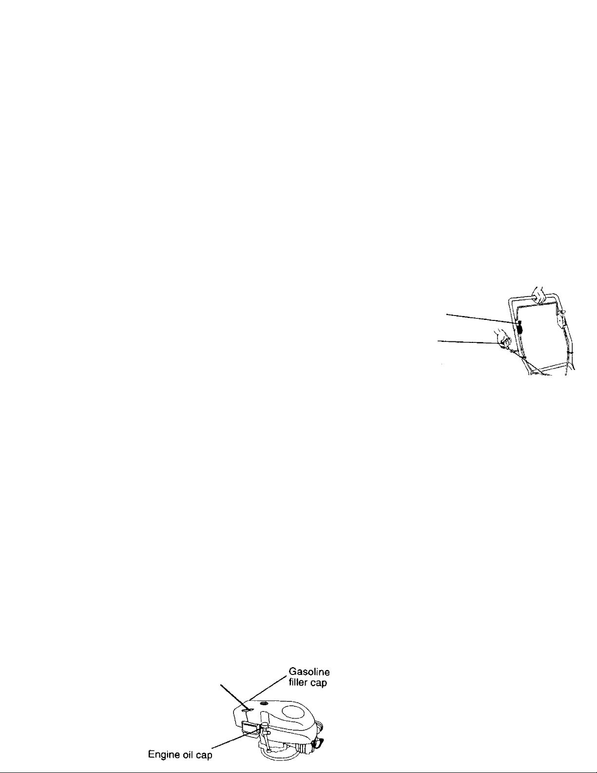
TO START ENGINE
• To start a cold engine, push primer three
(3) times before trying to start. Use a firm
push. This step is not usually necessary
when starting an engine which has
already run for a few minutes.
• Move throttle control lever to fast position.
• Hold upper handle firmly and pull starter
handle quickly. Do not allow starter rope 1
snap back.
TO STOP ENGINE
• To stop engine, move throttle control levet
to stop position.
NOTE: In cooler weather it may be
necessary to repeat priming steps. In
warmer weather overpriming may cause
flooding and engine will not start. If you
do flood engine, wait a few minutes
before attempting to start and do not
repeat priming steps.
Throttle
control
Starter
handle
TRIMMING TIPS
• Set the throttle control in the fast
position. If the weeds or grass are tall
and thick, operate the trimmer at a
slower walking speed.
• Frequently clean the underside of the
trimmer to remove any grass build up.
Keep top of engine around starter clear
and clean of grass clippings and chaff.
This will help engine air flow and extent
engine life. See TO REMOVE ENGINE
COVER in the Maintenance section of
this manual.
• For best results and longer lasting line,
use the ends of the line to do the cutting
This is easily done by moving slowly
through very thick and heavy weeds.
• Use the left side of trimmer when
trimming along fences, walls, flowerbed
and other such objects.
• If trimmer lines become too short, it will
take longer to complete the job. If
trimmer lines are worn to less than half
their original length, they should be
replaced. See TO REPLACE TRIMMER
LINE in the Maintenance section of this
manual.
• Trimmer head contact with concrete,
asphalt or other hard surfaces may
cause premature wear of the ball on
bottom of trimmer head.
Page 9

MAINTENANCE
Check for Loose Fasteners
Clean Trimmer - ✓
Clean Under Engine Cover
Check drive belt/pulleys
Check/Replace Trimmer Lines
Check Engine Oil Level
Change Engine Olí
Clean Air Filter
Inspect Muffler
Clean or Replace Spark Plug
Replace Air Filter Paper Cartridge
1 - Change more often when operating under a heavy load or in high ambient temperatures.
2 - Service more often when operating in dirty or dusty conditions.
3 - Replace trimmer lines when they have worn to half their original length.
GENERAL RECOMMENDATIONS
The warranty on this trimmer does not
cover items that have been subjected to
operator abuse or negligence. To receive
full value from the warranty, operator must
maintain trimmer as instructed in this
✓
✓ 2
✓
✓ a
✓
^1,2
✓ 2
✓
✓
i/i
IMPORTANT: Do not oil or grease plastic
wheel bearings. \^scous lubricants will attract
dust and dirt that will shorten the life of the
self- lubricating bearings. If you feel they must
be lubricated, use only a dry, powdered
graphite type lubricant sparingly.
manual.
Some adjustments will need to be made
periodically to properly maintain your unit.
All adjustments in the Service and
PRODUCT SPECIFICATIONS
Serial No. _______________________________
Date of Purchase: .
Adjustments section of this manual should
be checked at least once each season.
• Once a year, replace the spark plug
and replace air filter element. A new
spark plug and clean/new air filter
element assures proper air-fuel mixture
and helps your engine run better and
last longer.
• Follow the maintenance schedule in
Gasoline Type:
Gasoline Capacity:
Oil Type;
(APl-SF/SG/SH)
Oil Capacity:
Spark Plug :
(Gap: .030”)
Valve Clearance:
this manual.
BEFORE EACH USE
• Check engine oil level.
Trimmer Line Dia.: .130 inch
Trimmer Line Length: 16.75 inches
• Check for loose fasteners.
• Clean under engine cover.
LUBRICATION
To prolong the useful life of your trimmer,
change engine oil as recommended in
The model and serial numbers will be found on
a decal attached to the rear of the trimmer.
Record both serial number and date of
purchase in space provided above.
this section of Owner’s Manual.
✓
✓
✓
Unleaded Regular
1.25 Quarts
SAE 30 (Above 32= F)
SAE 5VJ-30 (Below 32= F)
20 Ozs.
Champion J19LM
or RJ19LM
Intake: .004-.008
Exhaust: .004-,008
9
Page 10

TRIMMER
Always observe safety rules when perform
ing any maintenance.
TIRES
• Keep tires free of gasoline, oil, or insect
control chemicals which can harm rubber.
• Avoid stumps, stones, deep ruts, sharp
objects and other hazards that may cause
tire damage.
TRIMMER LINE
For best results, replace trimmer lines
when they have worn to half their original
length. Use .130 inch diameter trimmer
line. Cut new trimmer line length to 16-3/4
inches. After new line is installed on
trimmer head, check all lines so they do
not vary more then one {1} inch in length.
This is important to make sure the trimmer
head is balanced and will not vibrate
abnormally.
^WARNING; Use only the specified
trimmer line. Do not use other materials
such as wire, string, rope, etc. Wire can
break off during trimming and become a
dangerous missile that can cause serious
injury.
TO REPLACE TRIMMER LINE
• Disconnect spark plug wire from spark
plug and place wire where it cannot
come in contact with spark plug.
• Remove worn trimmer line from line
carrier plate.
• Fold new, cut to length, trimmer line in
half and insert folded end through
carrier plate opening to back side of
retainer clip.
• With folded end of line at back side of
retainer clip, pull line outward until line
is fully seated under the retainer clip.
• Repeat on other side of carrier plate.
• Check all lines to be sure they are the
same length.
• Reconnect spark plug wire to spark
plug.
Trimmer
line
Carrier plate
opening
Retainer
clip
ENGINE
LUBRICATION
Use only high quality detergent oil rated
with API service classification SF, SG or
SFI. Select the oil's SAE viscosity grade
according to your expected operating
temperature.
SAE VISCOSITY GRADES
I I
I
C .30°
TEMPERATURE RANGE ANTICIPATED BEFORE NEXT OfL CHANGE
NOTE: Although multi-viscosity oils
(5W30, 10W30 etc.) improve starting in
cold weather, these multi-viscosity oils
will result in increased oil consumption
when used above 32°F. Check your
engine oil level more frequently to avoid
possible engine damage from running
low on oil.
Change the oil after every 25 hours of
operation or at least once a year if the
lawn mower is not used for 25 hours in
one year.
Check the crankcase oil level before
starting the engine and after each five (5)
hours of continuous use. Tighten oil plug
securely each time you check the oil
level.
•20*
30" 32" 40*
20* 30°
10
Page 11

TO CHANGE ENGINE OIL
NOTE: Before tipping trimmer to drain
oil, drain fuel lank by running engine
until fuel tank is empty.
• Disconnect spark plug wire from spark
plug and place wire where it cannot
come in contact with spark plug.
• Remove engine oil cap; lay aside on a
clean surface.
• Tip trimmer on its side as shown and
drain oil into a suitable container.
Rock trimmer back and forth to remove
any oil trapped inside of engine.
• Wipe off any spilled oil on trimmer and
on side of engine.
• Fill engine with oil. Fill only to the
"FULL“ line on the dipstick. DO NOT
overfill.
• Replace engine oil cap.
• Reconnect spark plug wire to spark
plug.
Turn
Collar
Slot
Air filter
Air filter
cover
Turn
counterclockwise to
tighten
clockwise
to remove
MUFFLER
Inspect and replace corroded muffler as
it could create a fire hazard and/or
damage.
Container
AIR FILTER
Your engine will not run properly and
may be damaged by using a dirty air
filter.
Replace the air filter every year, more
often if you mow in very dusty, dirty
conditions. Do not wash air filter.
TO CHANGE AIR FILTER
• Remove the air filter by turning
clockwise to the stop and pull away
from collar.
• Remove filter from inside of cover.
• Clean the inside of the cover and the
collar to remove any dirt accumulation.
• Insert new filter into cover.
• Put air filter cover and filter into collar
aligning the tab with the slot.
• Push in on cover and turn counter*
clockwise to tighten.
SPARK PLUG
Change your spark plug each year to
make your engine start easier and run
better. Set spark plug gap at .030 inch.
CLEANING
IMPORTANT: For best performance,
keep trimmer free of built-up grass and
trash. Clean the underside of your
trimmer after each use.
ACAUTION: Disconnect spark plug wire
from spark plug and place wire where it
cannot come in contact with the spark
plug.
• Turn trimmer on its side. Make sure air
filter and carburetor are up. Clean the
underside of your trimmer by scraping
to remove build-up of grass and trash.
• Clean engine often to keep trash from
accumulating. A clogged engine runs
hotter and shortens engine life.
• Keep finished surfaces and wheels
free of all gasoline, oil,etc.
• We do not recommend using a garden
hose to clean trimmer unless the
electrical system, muffler, air filter and
carburetor are covered to keep water
out. Water in engine can result in
shortened engine life.
11
Page 12

CLEAN UNDER ENGINE COVER
Clean under engine cover before each
use. or more frequently in heavy cutting
or dirty conditions. Engine cover screen
and engine air intake screen must be
kept free of dirt and chaff to prevent
engine damage from overheating.
Unscrew knob on top of cover.
Lift cover up and away from engine.
Clean cover and cover screen thor
oughly.
Clean top of engine and air intake
screen.
Replace engine cover and tighten
knob securely. Be sure the front tabs of
engine cover are located in the slots in
engine housing.
SERVICE AND ADJUSTMENTS
A CAUTION: Before performing any
service and adjustments:
• Stop engine.
• Make sure the rotating lines and all
moving parts have completely stopped.
• Disconnect spark plug wire from spark
plug and place where it cannot come in
contact with plug.
TRIMMER
TO REMOVE/REPLACE TRIMMER HEAD
DRIVE BELT
• Remove screw at front of chassis cover.
• Lift cover up and away from trimmer.
• Turn trimmer on its side with carburetor and
fuel cap up.
• Remove belt from engine pulley on
crankshaft.
• Remove belt from trimmer head pulley.
• Remove idler assembly from chassis
and remove belt and idler from trimmer.
Remove belt from idler assembly by
removing bottom belt keeper and idler
pulleys.
Assemble new belt, idler pulleys and
bottom belt keeper to idler bracket.
Tighten pulley bolts securely.
Be sure belt is inside top belt keeper on
idler assembly.
Position belt and idler assembly in
trimmer and assemble idler to chassis.
Tighten securely.
Install belt around trimmer head pulley
and engine pulley.
Replace chassis cover and tighten screw
securely.
Always use Craftsman replacement parts
to assure proper fit and long life.
12
Page 13

Chassis
Top belt
keeper
Flat idler
Bottom belt
keeper
Flat idler
Trimmer
head pulley
Bolt
ENGINE SPEED
Your engine speed has been factory set.
Do not attempt to increase engine speed
or it may result in persona! injury. If you
believe that the engine is running too fast
or too slow, take your unit to a Sears or
other qualified service center for repair
and/or adjustment.
CARBURETOR
Your carburetor has a nonadjustable fixed
main jet for mixture control. If your engine
does not operate properly due to sus
pected carburetor problems, take your
unit to a Sears or other qualified service
center for repair and/or adjustment.
IMPORTANT: Never tamper with the
engine governor, which is factory set for
proper engine speed. Overspeeding the
engine above the factory high speed
setting can be dangerous. If you think the
engine-governed high speed needs
adjusting, take your unit to a Sears or
other qualified service center, which has
proper equipment and experience to
make any necessary adjustments.
13
Page 14

STORAGE
Immediately prepare your trimmer for storage
at the end of the season or if the unit will not
be used for 30 days or more.
TRIMMER
When trimmer is to be stored for a period of
time, clean it thoroughly, remove alt dirt,
grease, leaves, etc. Store in a clean, dry area.
• Clean entire trimmer (See "CLEANING" in
the Maintenance section of this manual).
• Lubricate as shown in the Maintenance
section of this manual.
• Be sure that all nuts, bolts, screws, and pins
are securely fastened. Inspect moving
parts for damage, breakage and wear.
Replace if necessary.
• Touch up all rusted or chipped paint
surfaces: sand lightly before painting.
HANDLE
You can fold your trimmer handle for storage.
• Loosen handle knobs enough to allow
upper handle to be folded forward.
IMPORTANT: When folding the handle for
storage or transportation, be sure to fold the
handle as shown or you may damage the
control cables.
Upper
handle
Handle knob
ENGINE
FUELSYSTEM
IMPORTANT: It is important to prevent gum
deposits from forming in essential fuel system
parts such as carburetor, fuel filter, fuel hose
or tank during storage. Also, experience
indicates that alcohol blended fuels ( called
gasoho! or using ethanol or methanol) can
attract moisture which leads to separation and
formation of acids during storage. Acidic gas
can damage the fuel system of an engine
while in storage.
• Drain the fuel tank.
• Start the engine and let it run until the fuel
lines and carburetor are empty.
• Never use engine or carburetor cleaner
products in the fuel tank or permanent
damage may occur,
• Use fresh fuel next season.
NOTE: Fuel stabili2er is an acceptable
alternative in minimizing the formation of fuel
gum deposits during storage. Add stabilizer
to gasoline in fuel tank or storage container.
Always follow the mix ratio found on stabilizer
container. Run engine at least 10 minutes
after adding stabilizer to allow the stabilizer to
reach the carburetor. Do not drain the gas
tank and carburetor if using fuel stabilizer.
ENGINE OIL
Drain oil (with engine warm) and replace with
clean engine oil. (See "ENGINE" in the
Maintenance section of this manual).
CYLINDER
• Remove spark plug.
• Pour one ounce (29 ml) of oil through
spark plug hole into cylinder.
• Pull starter handle slowly a few times to
distribute oil.
• Replace with new spar1< plug.
OTHER
• Do not store gasoline from one season to
another.
• Replace your gasoline can if your can
starts to rust. Rust and/or dirt in your
gasoline will cause problems.
• If possible, store your unit indoors and
cover it to give protection from dust and dirt.
• Cover your unit with a suitable protective
cover that does not retain moisture. Do
not use plastic. Plastic cannot breathe
which allows condensation to form and will
cause your unit to rust.
IMPORTANT: Never cover trimmer while
engine and exhaust areas are still warm.
^CAUTION: Never store the trimmer
with gasoline in the tank inside a building
where fumes may reach an open flame or
spark. Allow the engine to cool before
storing in any enclosure.
14
Page 15

TROUBLESHOOTING CHART
PROBLEM CAUSE
CORRECTION
Does not start 1. Dirty air filter.
2. Out of fuel.
3. Stale fuel.
4. Water in fuel.
5. Sparkplug wire is
disconnected.
6. Bad spark plug.
7. Throttle control lever not
in correct position
(if equipped).
Loss of power
Excessive
Vibration
1. Dirty air filter.
2. Buildup of grass, leaves,
and trash under trimmer.
3 Too much oil in engine.
4. Walking speed too fast.
1. Lines uneven or broken.
2. Loose nuts or bolts.
3. Damaged trimmer head.
1. Clean/replace air filter.
2. Fill fuel tank.
3. Drain tank and refill with
fresh clean fuel.
4. Dram fuel tank and
carburetor and refill tank
with fresh gasoline.
5. Connect wire to plug.
6. Replace spark plug.
7. Move throttle lever to FAST
position.
1. Clean/replace air filter.
2. Clean underside of trimmer
and trimmer head.
3. Check oil level.
4. Trim at slower walking
speed.
1. Check trimmer lines.
2. Check all hardware,
including engine bolts.
3. Check/repair trimmer head.
Starter rope hard
to pull
Loss of head
drive
Poor trimming
performance
Trimmer head
does not
retain line
1. Bent engine crankshaft. 1. Contact a Sears or other
qualified service center.
1. Belt not driving.
1. Trimmer line length is
too short.
2. Throttle control lever not
in correct position
(if equipped).
1. Trimmer line not
properly installed.
2. Broken line retainer clip.
3. Incorrect size of
trimmer line.
1. Put belt on pulleys or
replace belt if broken.
1. If line is worn or broken to
half original length,
replace line.
2. Move throttle lever to FAST
position.
1. Follow instructions in
Maintenance section.
2. Replace string carrier plate
assembly.
3. Use .130 diameter
trimmer line.
15
Page 16

REPAIR PARTS
CRAFTSMAN WEED TRIMMER- - MODEL NO. 917.773410
30
Page 17

CRAFTSMAN WEED TRIMMER- - MODEL NO. 917.773410
KEY
10
11
12
16
17
18
19
20
21
22
23
24
25
26
27
28
29 174034
30
31
- -
- -
PART
NO.
NO.
1
2
150406
3
169791
4
STD502502
5 174317
6 174274
7
174030
8
169821X479
9
150078
169797X479
131959
136376
153638
STD541025
66426
171449
174038
158755
169787
150078
169789
57143
169795
83923
174037
174032
172221
169803
169804
DESCRIPTION
Engine Model No. 143.004008
(See Breakdown)
Engine Bolt 3/8-16
Engine Pulley (Includes setscrew)
Setscrew, Pulley
Engine Cover w/screen
Engine Cover Knob
Engine Cover Stud
LowerHandle
Screw Hx Wshd 5/16-18 x .75
Upper Handle
Handle Bolt
Handle Knob
Rope Guide
Locknut 1/4 X 20
Wire Tire
Control Bar
Throttle Control
Hex Washer Screw
Axle Shaft
Screw hex Wshd 5/16-18 x .75
Axle Spacer
Wave Washer
Wheel 10 X 1.75
Hex Flange Locknut 3/8-16
Drive Control
Decal - Warning
Decal - Engine Cover
Bracket - Axle Support
Safety Goggles (Not Shown)
Owner's Manual
Available accessories not included with trimmer:
7133623 Gas Can (2.5 gal.)
7133000 SAE 30W Oil (20 oz.)
7179996 Trimmer Line (Pack of 24 strings, .130 dia.)
7185642 Trimmer Line Bulk Pack( 150 Feet, .130 dia.'
'31
Page 18

CRAFTSMAN WEED TRIMMER- - MODEL NO. 917.773410
32
Page 19

CRAFTSMAN WEED TRIMMER- - MODEL NO. 917.773410
KEY
NO.
10 160829
11
12 173717
13 142748
14
15
16
17
18 85768 Screw #10-24 X 3/4
19 169800
20 169764
21
22 STD541137
23 STD551137
24
25
26 172551 Spacer - Pulley
27
28 172603
29 169766X459 Cover, Bottom
30 174543
31 174581
34
35 172635 Spacer
36
37
38 172523 Mow Ball
39 172636 Bolt, Mow Ball
40 173619
41
42
43 174036
45 174596
PART
NO. DESCRIPTION
1
174024X459
2
174040 Line .130 Dia x 16.75
3 174591
4
169790 BeltV
5 172145X004
6 166042 Idler Pulley V-Groove
7 173716
8 751592
9 166043
155552 Locknut 5/16-18
145212
173811 Return Spring
170552
57808
149746 Screw #10-24 X 1-3/4
STD551037
169792
174549 Bearing
173531
172516 Cover, Bearing
174580 Retaining Ring 40mm internal
174029 Spacer
751153
Chassis Assembly
Screw 5/16-18 X 1
Idler Bracket
Hex Bolt 3/8-16x1.25
Hex Locknut 3/8-16
Idler Pulley-Flat
Shoulder Bolt
Spacer
Shoulder Bolt
Flange Locknut
Debris Shield
Screw 1/4-20 X 1/2
Skirt
Chassis Cover-Top
Nut3/8-24UNF
Lockwasher 3/8
Flatwasher3/8
Pulley - Driven
Jackshaft
Spindle Hsg, Asm. (* Includes Upper Bearing Key No. 27)
Retaining Ring 17mm External
Carrier Plate Assembly (Fixed)
Head Assembly Complete (Includes Key Nos. 22-39)
Locknut Flanged 5/16-18
Decal - Instruction
Bottom Belt Keeper
33
Page 20

CRAFTSMAN 4-CYCLE ENGINE
MODEL NO. 143.004008
250
34
Page 21

CRAFTSMAN 4-CYCLE ENGINE
MODEL NO. 143.004008
KEY PART
NO.
NO. DESCRIPTION
1 .
37266 Cylinder (Incl. 2,20 & 150)
2
26727
Dowel Pin
6 33734 Breather Element
7
36557
2
36775 Breather Tube
12A
36558 Breather Cover & Tube
Breather Assy (Incl. 6 & 12A)
(Incl. 12B)
12B
36694
14
28277 Washer
Breather Tube Elbow
15 30589 Governor Rod (Incl. 14)
16 34839A Governor Lever
17
31335 Governor Lever Clamp
18
651018 Screw, Torx T-15,
8-32 X 19/64"
19
37453 Extension Spring
20
32600 Oil Seal
30
36797
40
40004 Piston, Pin & Ring Set (Std.)
Crankshaft
40005 Piston, Pin & Ring Set
(.010“ OS)
41
36070 Piston & Pin Ass’y. (Std.)
(Incl. 43}
36071
Piston & Pin Ass’y. (.010" OS)
(Incl. 43}
42
40006 Ring Set (Std.)
43
45
40007
20381
36777
Ring Set (.010" OS)
Piston Pin Retaining Ring
Connecting Rod Ass'y.
(Incl. 46)
46 3261OA
48 27241
50
37460
Connecting Rod Bolt
Valve Lifter
Camshaft (Exhaust MCR)
(Inc. ref 104)
52
69
70
29914
37130 *
34311E
Oil Pump Ass’y.
Mounting Flange Gasket
Mounting Flange
(Incl. 72 thru 83,306)
72
36083
75 27897
80
30574A
81 30590A
82
30591
83
30588A
86
650488
89
610961
90
611213
92
650815
93
650816
100
34443B
101
610118
103 651007
Oil Drain Plug
Oil Seal
Governor Shaft
Washer
Governor Gear Ass’y. (Incl. 81)
Governor Spool
Screw, 1/4-20 X 1-1/4"
Flywheel Key
Flywheel
Belleville Washer
Flywheel Nut
Solid State Ignition
Spark Plug Cover
Screw, Torx T-15,
10-24 X 15/16"
104
37480
1 10 36230
119 36787 *
120
36825
125
37288
Cam Bushing
Ground Wire
Cylinder Head Gasket
Cylinder Head
Exhaust Valve (Std.)
(incl. 151) „
126
37289
Intake Valve (Std.) (Incl. 151)
KEY PART
NO.
NO.
130 6021A
135
35395
150 31672
151 31673
151A40017
169 36783 *
172 36784
174
30200
178 29752
179 30593
182 6201
184
26756 *
DESCRIPTION
Screw, 5/16-18 X 1-1/2"
Resistor Spark Plug (RJ19LM)
Valve Spring
Valve Spring Cap
Intake Valve Seal
Valve Cover Gasket
Valve Cover
Screw, 10-24 x 9/16”
Nut & Lock Washer, 1/4-28
Retainer Clip
Screw, 1/4-28 x 7/8"
Carburetor To Intake Pipe
Gasket
185 36785
Intake Pipe
186 36201 Governor Link
37134
200
206 610973
207
36200B
209 30200
223 650451
224
36786 *
238 650932
239 34338 *
241
36919 Air Cleaner Collar
245 36905
250 37122
260 37213
261 30200
262
650831
367Э0А
275
277 650988
35000A
285
287
650926 Screw, 8-32 X 21/64"
290 34357
292
26460 Fuel Line Clamp
300
35586 Fuel Tank (Incl. 292 & 301)
Control Bracket (Incl. 206)
Terminal
Throttle Link
Screw, 10-24 X 9/16“
Screw. 1/4-20 x 1"
Intake Pipe Gasket
Screw, 10-32 X 49/64"
Air Cleaner Gasket
Air Cleaner Filter
Air Cleaner Cover
Blower Housing
Screw, 10-24 x^9/16"
Screw, 1/4-20 X 1/2“
Muffler
Screw, 1/4-20 x 2-9/32"
Starter Cup
Fuel Line
301 36246 Fuel Cap
35577
305
Oil Fill Tube
306 36996 * “О’’-Ring
307
35499 “0’’-Ring
309 650562 Screw, 10-32 X 3/8"
310
35578
313 34080
370C37318
380
640262
Dipstick
Spacer
Primer Decal (3X)
Carburetor (Incl. 184)
390 590739 Rewind Starter
400 36792B
Gasket Set
(Incl. Items Marked *)
416 36085
Spark Arrestor Kit
(Incl. 417)(Optional)
417 650821
—
900
_
___
_
_
________
_
Screw. 10-32 X 1/2" (Optional)
REPLACEMENT SHORT
BLOCK 750812C
RPM High 3450 to 3750
RPM Low 2000 to 2300
NOTE: This engine could have been built with
590702 starter
NOTE: All component dimensions given in U.S.
inches 1 inch = 25.4 mm
35
Page 22

CRAFTSMAN 4-CYCLE ENGINE MODEL NO. 143.004008
36
Page 23

CRAFTSMAN 4-CYCLE ENGINE
PART
KEY
NO. NO.
_ _
640262
1 631615
2 631767
4 631184
5 631183
6 640070
7 650506
631807
16
17 651025
18 630766
640018
20
20A 640200
631867
25
27 631024
632019
28
631028
29
30 631021
31 631022
35 640259
36 640080
36A 632766
37 632547
40
640175
44
27110A
47 630748
48 631027
60 632760B
DESCRIPTION
Carburetor {Incl. 184 of Engine Parts List)
Throttle Shaft & Lever Assembly
Throttle Return Spring
*
Dust Seal Washer
*
Dust Seal (Throttle)
Throttle Shutter
Shutter Screw
Fuel Fitting
Throttle Crack Screw/ldle Speed Screw
Tension Spring
Idle Restrictor Screw
Idle Restrictor Scrwe Cap (Black)
Float Bowl
-*
Float Shaft
Float
Float Bowl "O” Ring
it
Inlet Needle, Seat, & Clip (Incl. 31)
Spring Clip
Primer Buib/Retainer Ring
Main Nozzle Tube
Carburetor Tube
*
"0” Ring, Main Nozzle Tube
High Speed Bowl Nut
-*
Bowl Nut Washer
-*
Welch Plug, Idle Mixture Well
*
Welch Plug, Atmospheric Vent
Repair kit (Incl. Items Marked *)
MODEL NO. 143.004008
37
Page 24

CRAFTSMAN 4-CYCLÈ ENGINE MODEL NO. 143.004008
KEY
PART
NO.
NO.
____
590702 Recoil Starter
1
590599A
2
590600
3
590696 Retainer
4
590601 Washer
5
590697 Brake Spring
6
590698
7
590699 Dog Spring
8
590700
11
590703
12
590535
13
590701
0—2
0
-
DESCRIPTION
Spring Pin (Ind. 4)
Washer
Starter Dog
Pulley & Rewind Spring Ass’y-
Starter Housing Ass’y. {40
degree grommet)
Starter Rope ( 98" X 9/è4"
día.)
Starter Handle
38
Page 25

CRAFTSMAN 4-CYCLE ENGINE
MODEL NO. 143.004008
-u
KEY
PART
NO.
NO. DESCRIPTION
____
590739 Rewind Starter
3 590740
6 590616 Starter Dog
7
590617
8 590618A
1 1
590638
12 590535
13 590701
14 590760
Retainer
Dog Spring
Pulley & Rewind Spring Ass’y
Starter Housing Ass’y (40
degree grommet)
Starter Rope (Length 98" x 9/
64" dia.)
Starter Handle
Spring Clip
39
Page 26

Get it fixed, at your home or ours!
For repair of major brand appliances in your own home...
no matter who made it, no matter who sold it'
1-800-4-MY-HOME Anytime, day or night
(1-800-469-4663)
www.sears.com
To bring in products such as vacuums,
lawn equipment and electronics for repair, call for
the location of your nearest Sears Parts & Repair Center.
1-800-488-1222 Anytime, day or night
www.sears.com
For the replacement parts, accessories and owner’s manuals
that you need to do-it-yourself, call Sears PartsDirect^'^l
1 -800-366-PART 6 a m - 11 p m CST,
(1-800-366-7278) 7 days a week
www.sears.com/partsdirect
To purchase or inquire about a Sears Service Agreement:
1-800-827-6655
7 a.m. - 5 p.m, CST, Mon - Sat
Рага pedir servicio de reparación a domicilio,
у para ordenar piezas con entrega a domicilio
1-888-SU-HOGAR^"
(1-888-784-6427)
HomeCentral
I Sears, Roebuck and Co
) Registered Trademark / Trademark of Sears, Roebuck and Co
> Marca Registrada / ™ Marca de Fábrica de Sears, Roebuck and Co
Au Canada pour service en français
1-877-LE-FOYER"“
(1-877-533-6937)
169804 Rev.3 04.19.00 VB
Printed in U.S.A.
 Loading...