

Page 1
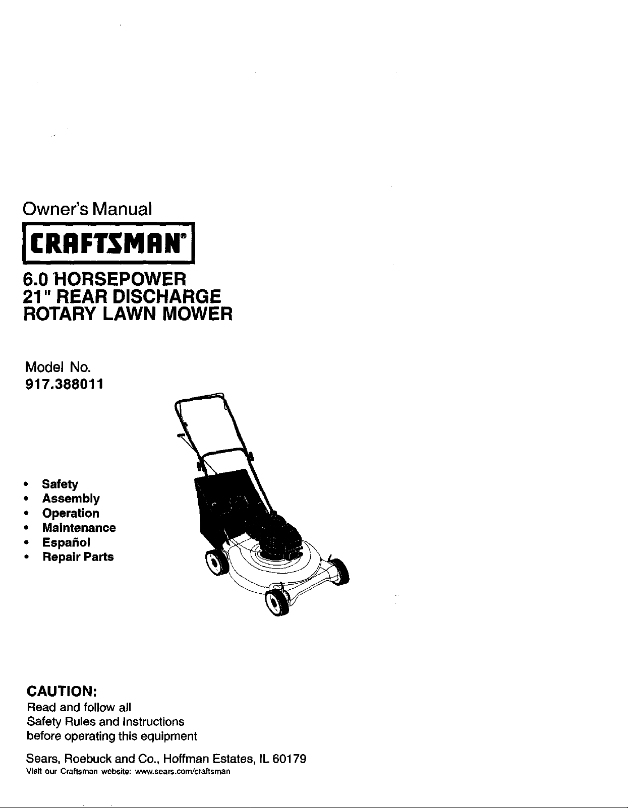
Owner's Manual
6.0 HORSEPOWER
21" REAR DISCHARGE
ROTARY LAWN MOWER
Model No.
917.388011
• Safety
• Assembly
• Operation
• Maintenance
• EspaSol
• Repair Parts
CAUTION:
Read and follow all
Safety Rules and Instructions
before operating this equipment
Sears, Roebuck and Co., Hoffman Estates, IL 60179
Visit our Craftsman website: www.sears,com/craftsman
Page 2
Warranty ............................................... 2
Safety Rules ......................................... 2
Assembly .............................................. 5
Operation .............................................. 6
Maintenance Schedule ...................... 10
Maintenance ....................................... 10
LIMITED TWO YEAR WARRANTY ON CRAFTSMAN POWER MOWER
For two years from date of purchase, when this Craftsman Lawn Mower is maintained,
lubricated, and tuned up according to the operating and maintenance instructions in
the owner's manual, Sears will repair free of charge any defect in material or work-
manship.
If this Craftsman Lawn Mower is used for commercial or rental purposes, this warranty
applies for only 90 days from the date of purchase.
This Warranty does not cover:
• Expendable items which become worn during normal use, such as rotary mower
blades, blade adapters, belts, air cleaners and spark plug.
• Repairs necessary because of operator abuse or negligence, including bent
crankshafts and the failure to maintain the equipment according to the instructions
contained in the owner's manual.
Warranty service is available by retuming the Craftsman power mower to the nearest
Sears Service Center/Department in the United States. This warranty applies only
while this product is in use in the United States.
This Warranty gives you specific legal rights, and you may also have other rights
which vary from state to state.
SEARS, ROEBUCK AND CO., D/817 WA, HOFFMAN ESTATES, ILLINOIS 60179
Product Specifications ........................ 11
Service and Adjustments .................... 14
Storage ............................................... f5
Troubleshooting ................................. 16
Repair Parts ........................................ 35
Parts Ordering ..................... Back Cover
IMPORTANT: This cutting machine is capable of amputating hands and feet and
throwing objects. Failure to observe the following safety instructions could result in
serious injury or death.
I.GENERAL OPERATION
• Read, understand, and follow all
instructions on the machine and in the
manual(s) before starting. Be thor-
oughly familiar with the controls and
the proper use of the machine before
starting.
• Do not put hands or feet near or under
rotating parts. Keep clear of the
discharge opening at all times.
• Only allow responsible individuals,
who are familiar with the instructions, to
operate the machine.
• Clear the area of objects such as
rocks, toys, wire, bones, sticks, etc.,
which could be picked up and thrown
by the blade.
• Be sure the area is clear of other
people before mowing. Stop machine if
anyone enters the area.
• Do not operate the mower when
barefoot or wearing open sandals.
Always wear substantial foot wear.
• Do not pull mower backwards unless
absolutely necessary. Always look
down and behind before and while
moving backwards.
• Do not operate the mower without
proper guards, plates, grass catcher or
other safety protective devices in place.
• See manufacturer's instructions for
proper operation and installation of
accessories. Only use accessories
approved by the manufacturer.
2
Page 3
• Stop the blade(s) when crossing gravel
ddves, walks, or roads.
• Stop the engine (motor) whenever you
leave the equipment, before cleaning
the mower or unclogging the chute.
• Shut the engine (motor) off and wait
until the blade comes to complete stop
before removing grass catcher.
• Mow only in daylight or good artificial
light.
• Do not operate the machine while
under the influence of alcohol or drugs.
• Never operate machine in wet grass.
Always be sure of your footing: keep a
firm hold on the handle and walk; never
run.
• Disengage the self-propelled mecha-
nism or drive clutch on mowers so
equipped before starting the engine
(motor).
• If the equipment should start to vibrate
abnormally, stop the engine (motor)
and check immediately for the cause.
Vibration is generally a warning of
trouble.
• Always wear safety goggles or safety
glasses with side shields when
operating mower.
I1.SLOPE OPERATION
Slopes are a major factor related to slip
and fall accidents which can result in
severe injury. All slopes require extra
caution. If you feel uneasy on a slope, do
notmow it.
DO:
• Mow across the face of slopes: never
up and down. Exercise extreme caution
when changing direction on slopes.
• Remove obstacles such as rocks, tree
limbs, etc.
• Watch for holes, ruts, or bumps. Tall
grass can hide obstacles.
DO NOT:
• Do not trim near drop-offs, ditches or
embankments. The operator could lose
footing or balance.
• Do not tdm excessively steep slopes.
• Do not mow on wet grass. Reduced
footing could cause slipping.
III. CHILDREN
Tragic accidents can occur if the operator
is not alert to the presence of children.
Children are often attracted to the
machine and the mowing activity. Never
assume that children will remain where
you last saw them.
• Keep children out of the trimming area
and under the watchful care of another
responsible adult.
• Be alert and turn machine off if children
enter the area.
• Before and while walking backwards,
look behind and down for small
children.
• Never allow children to operate the
machine.
• Use extra care when approaching blind
comers, shrubs, trees, or other objects
that may obscure vision.
IV. SERVICE
• Use extra care in handling gasoline
and other fuels. They are flammable
and vapors are explosive.
-Use only an approved container.
-Never remove gas cap or add fuel
with the engine running. Allow
engine to cool before refueling. Do
not smoke.
-Never refuel the machine indoors.
-Never store the machine or fuel
container inside where there is an
open flame, such as a water heater.
• Never run a machine inside a closed
area.
• Never make adjustments or repairs with
the engine (motor) running. Disconnect
the spark plug wire, and keep the wire
away from the plug to prevent acciden-
tal starting.
• Keep nuts and bolts, especially blade
attachment bolts, tight and keep
equipment in good condition,
• Never tamper with safety devices.
Check their proper operation regularly.
• Keep machine free of grass, leaves, or
other debds build-up. Clean oil or fuel
spillage. Allow machine to cool before
storing.
• Stop and inspect the equipment if you
stdke an object. Repair, if necessary,
before restarting.
• Never attempt to make wheel height
adjustments while the engine (motor) is
running.
• Grass catcher components are subject
to wear, damage, and deterioration,
which could expose moving parts or
allow objects to be thrown. Frequently
check components and replace with
manufacturer's recommended parts,
when necessary.
• Mower blades are sharp and can cut.
Wrap the blade(s) or wear gloves, and
use extra caution when servicing them.
• Do not change the engine governor
setting or overspeed the engine.
3
Page 4
_Look for this symbol to point out
important safety precautions. It means
CAUTIONI!! BECOMEALERT!rr YOUR
SAFETY IS INVOLVED.
A WARNING= In order to prevent
accidental starting when setting up,
transporting, adjusting or making repairs,
always disconnect spark plug wire and
place wire where it cannot contact spark
plug.
_IWARNING: Engine exhaust, some of its
constituents, and certain vehicle compo-
nents contain or emit chemicals known to
the State of California to cause cancer
and birth defects or other reproductive
harm.
;IWARNING: Battery posts, terminals and
related accessories contain lead and
lead compounds, chemicals known to the
State of California to cause cancer and
birth defects or other reproductive harm.
Wash hands after handling.
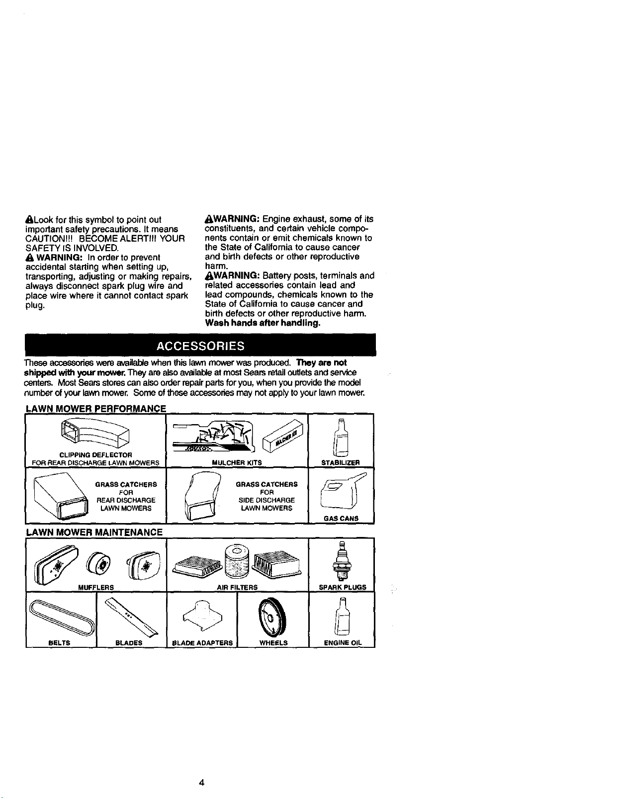
Theseaccassori_wereavailai:x'ewhenthislawnmowerwasproduced,Theyare not
shippedwithyourmower.TheyarealsoavailableatmastSearsretailoutletsandservice
centers.MostSearsstorescanalsoorderrepairpartsforyou,whenyouprovidethe model
numberofyourlawnmower.Someoftheseaccessoriesmaynotapplytoyourlawnmower.
LAWN MOWER PERFORMANCE
CLIPPING DEFLECTOR
FOR REAR DISCHARGE LAWN MOWERS MULCHER KITS STABILIZER
REAR DISCHARGE SIDE DISCHARGE
LAWN MOWERS LAWN MOWERS
GAS CANS
LAWN MOWER MAINTENANCE
MUFFLERS AIR FILTERS SPARK PLUGS
BELTS BLADES BLADE ADAPTERS WHEELS ENGINE OIL
4
Page 5
Readtheseinstructionsandthis manual
in its entirety before you attempt to
assemble or operate your new lawn
mower.
IMPORTANT: This lawn mower is
shipped WITHOUT OIL OR GASOLINE in
the engine.
Your new lawn mower has been as-
sembled at the factory with the exception
of those parts left unassembled for
shipping purposes. All parts such as nuts,
washers, bolts, etc., necessary to com-
plete the assembly have been placed in
the parts bag. To ensure safe and proper
operation of your lawn mower, all parts
and hardware you assemble must be
tightened securely. Use the correct tools
as necessary to ensure proper tightness.
TO REMOVE LAWN MOWER FROM
CARTON
1. Remove loose parts included with
mower.
2. Cut down two end comers of carton
and lay end panel down flat.
3. Remove all packing materials except
padding between upper and lower
handle and padding holding operator
presence control bar to upper handle.
4. Roll lawn mower out of carton and
check carton thorougly for additional
loose pads.
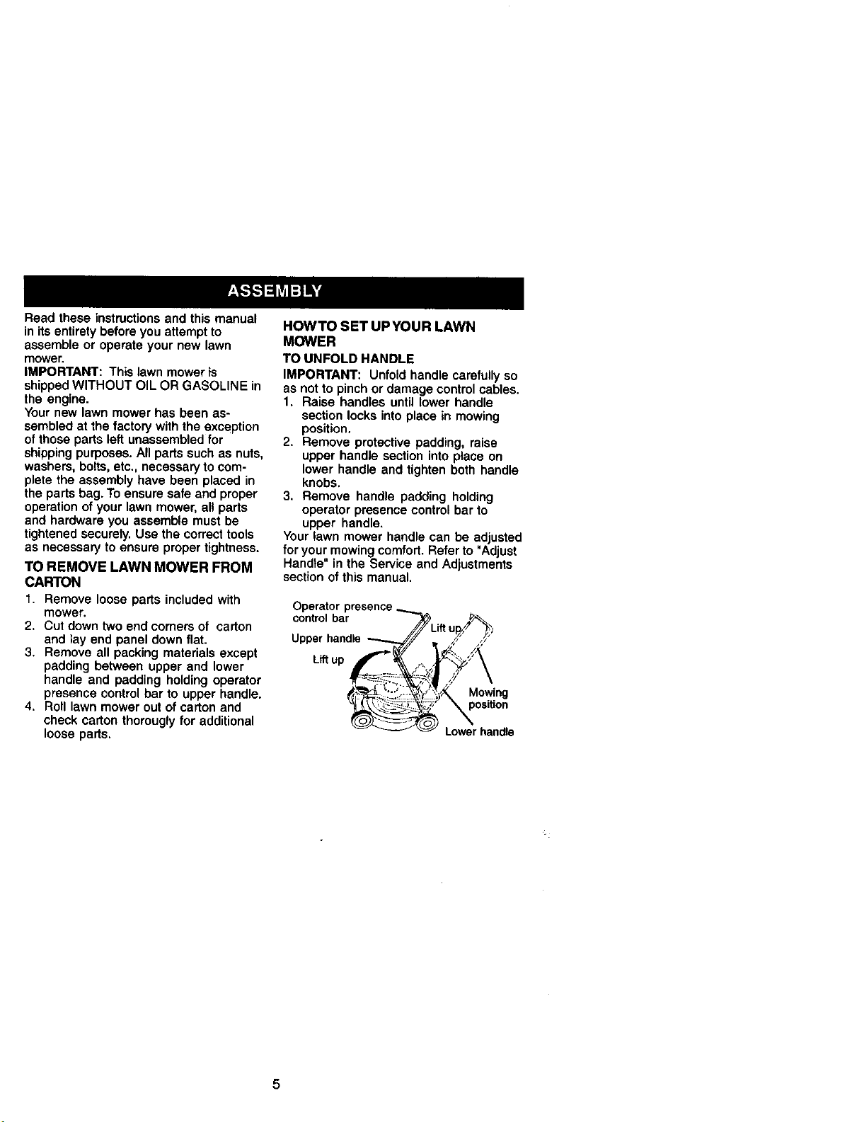
HOWTO SET UPYOUR LAWN
MOWER
TO UNFOLD HANDLE
IMPORTANT: Unfold handle carefully so
as not to pinch or damage control cables.
1. Raise handles until lower handle
section locks into place in mowing
position.
2. Remove protective padding, raise
upper handle section into place on
lower handle and tighten both handle
knobs.
3. Remove handle padding holding
operator presence control bar to
upper handle.
Your lawn mower handle can be adjusted
for your mowing comfort. Refer to "Adjust
Handle" in the Service and Adjustments
section of this manual.
Operator
control bar
Upper handle
L_ up
Mowing
Lower handle
5
Page 6
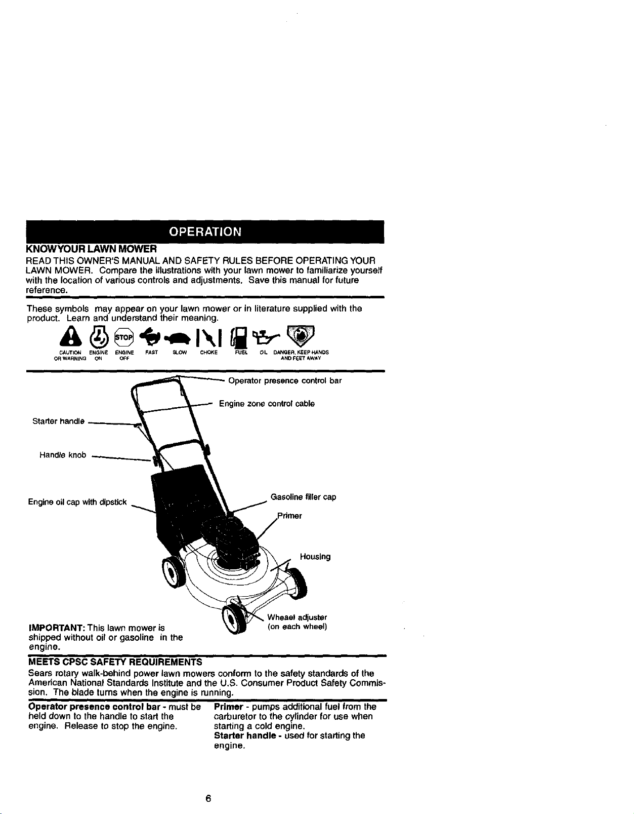
KNOWYOUR LAWN MOWER
READ THIS OWNER'S MANUAL AND SAFETY RULES BEFORE OPERATING YOUR
LAWN MOWER. Compare the illustrations with your lawn mower to familiarize yourself
with the location of vadous controls and adjustments. Save this manual for future
reference.
These symbols may appear on your lawn mower or in literature supplied with the
product. Learn and understand their meaning.
CAUTION ENGINE ENGINE FAST SLOW CHOKE FU_L OIL DANGER. KEEP HANDS
OR WARNING ON OFF AND F_ET AWAY
Operator presence control bar
Engine zone control cable
Starter handle
Handle knob
Engine oil cap with dipstick
IMPORTANT: This lawn mower is
Gasoline filler cap
Housing
Whesel adjuster
(on each wheel)
shipped without oil or gasoline in the
engine.
MEETS CPSC SAFETY REQUIREMENTS
Sears rotary walk-behind power lawn mowers conform to the safety standards of the
American National Standards Institute and the U.S. Consumer Product Safety Commis-
sion. The blade turns when the engine is running.
Operator presence control bar - must be Primer - pumps additional fuel from the
held down to the handle to start the carburetor to the cylinder for use when
engine. Release to stop the engine, stading a cold engine.
Starter handle - used for starting the
engine.
6
Page 7
The operation of any lawn
mower can result in
foreign objects thrown into
the eyes, which can result
in severe eye damage.
Always wear safety glasses or eye
shields while operating your lawn mower
or performing any adjustments or repairs.
We recommend a wide vision safety
mask over spectacles or standard safety
glasses.
HOWTO USEYOUR LAWN MOWER
ENGINE SPEED
The engine speed was set at the factory
for optimum performance. Speed is not
adjustable.
ENGINE ZONE CONTROL
_CAUTION: Federal regulations require
an engine control to be installed on this
lawn mower in order to minimize the risk
of blade contact injury. Do not under any
circumstances attempt to defeat the
function of the operator control. The blade
turns when the engine is running.
• Your lawn mower is equipped with an
operator presence control bar which
requires the operator to be positioned
behind the lawn mower handle to start
and operate the lawn mower.
TO ADJUST CUTTING HEIGHT
Raise wheels for low cut and lower
wheels for high cut, adjust cutting height
to suityour requirements. Medium
position is best for most lawns.
• To change cutting height, squeeze
adjuster lever toward wheel. Move
wheel up or down to suit your require-
ments. Be sure all wheels are inthe
same setting.
NOTE: Adjuster is properly positioned
when plate tab inserts into hole in lever.
Also, 9-position adjusters (if so equipped)
allow lever to be positioned between the
plate tabs.
PlateTab
LowerWheels for High Cutr-_L,__h=t-J_,_
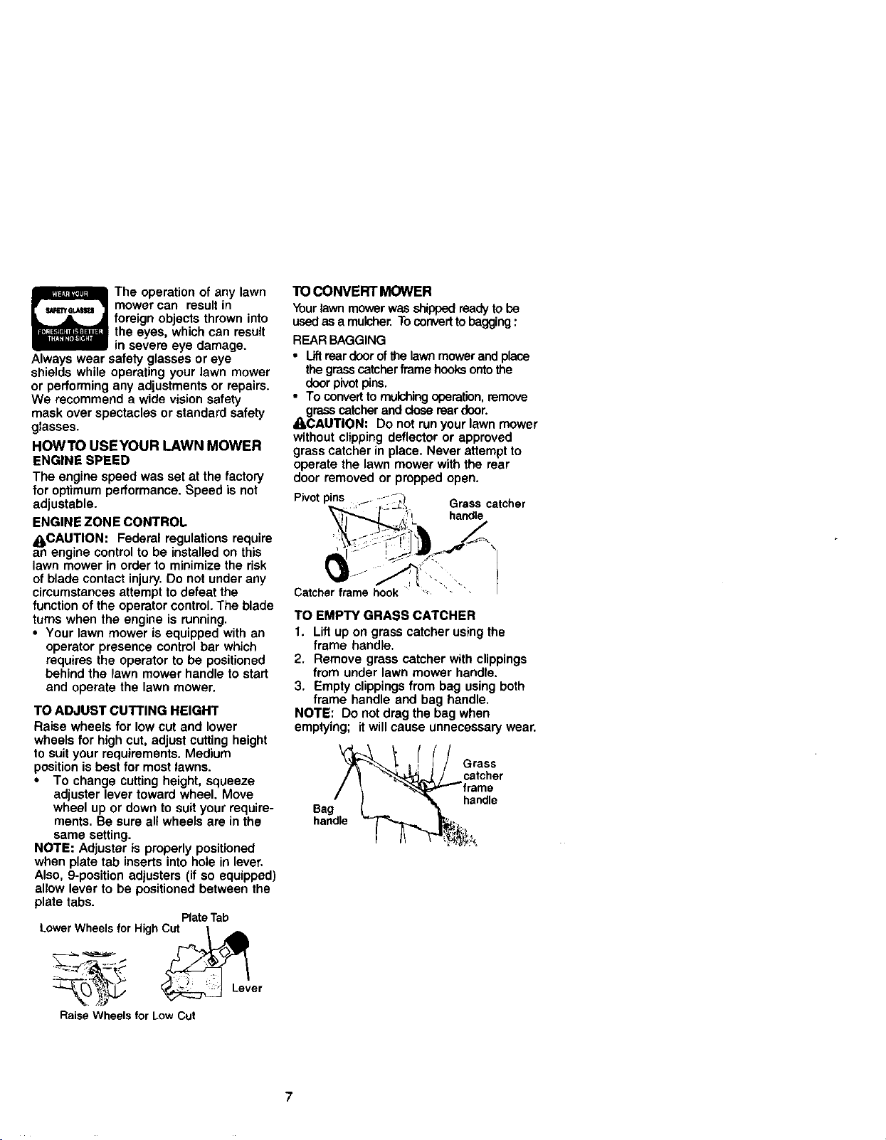
TO CONVERT MOWER
Yourlawn mower was shipped ready to be
usedas a mulcher. Toconvertto begging :
REAR BAGGING
• lift rear doorofthe lawn mower and place
the grass catcher frame hooks onto the
door pivotpins.
• To convert to mulchingoperation,remove
grass catcher and close rear door.
_I_CAUTION: Do not run your lawn mower
without clipping deflector or approved
grass catcher in place. Never attempt to
operate the lawn mower with the rear
door removed or propped open.
Pivotpins f /_
1,.._ , " _ _ Grass catcher
/- _':_ handle
L =_ '.
Catcher frame hook _
TO EMPTY GRASS CATCHER
1. Lift up on grass catcher using the
frame handle.
2. Remove grass catcher with clippings
from under lawn mower handle.
3. Empty clippings from bag using both
frame handle and bag handle.
NOTE: Do not drag the bag when
emptying; itwill cause unnecessary wear.
Grass
catcher
Bag
handle
handle
RaiseWheels for LowCut
7
Page 8
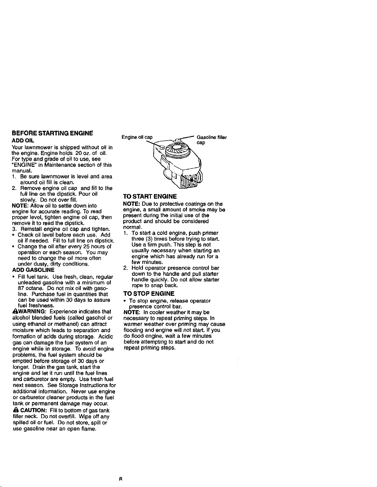
BEFORE STARTING ENGINE
ADD OIL
Your lawnmower is shipped without oil in
the engine. Engine holds 20 oz. of oil.
For type and grade of oilto use, see
"ENGINE" in Maintenance section of this
manual.
1. Be sure lawnmower is level and area
around oil fig is clean.
2. Remove engine oil cap and fill to the
full line on the dipstick. Pour oil
slowly. Do not over fill.
NOTE: Allow oil to settle down into
engine for accurate reading. To read
proper level, tighten engine oil cap, then
remove it to read the dipstick.
3, Reinstall engine oil cap and tighten.
• Check oil level before each use. Add
oil if needed. Fill to full line on dipstick.
• Change the oil after every 25 hours of
operation or each season. You may
need to change the oil more often
under dusty, dirty conditions.
ADD GASOLINE
• Fill fuel tank. Use fresh, clean, regular
unleaded gasoline with a minimum of
87 octane. Do not mix oil with gaso-
line. Purchase fuel in quantities that
can be used within 30 days to assure
fuel freshness.
_I_WARNING: Experience indicates that
alcohol blended fuels (called gasohol or
using ethanol or methanol) can attract
moisture which leads to separation and
formation of acids dudng storage. Acidic
gas can damage the fuel system of an
engine while in storage. To avoid engine
problems, the fuel system should be
emptied before storage of 30 days or
longer. Drain the gas tank, start the
engine and let it run until the fuel lines
and carburetor are empty. Use fresh fuel
next season. See Storage Instructions for
additional information. Never use engine
or carburetor cleaner products in the fuel
tank or permanent damage may occur.
CAUTION: Fill to bottom of gas tank
filler neck. Do not overfill. Wipe off any
spilled oil or fuel. Do not store, spill or
usa gasoline near an open flame.
Engine oilcap Gasolinefiller
cap
TO START ENGINE
NOTE: Due to protective coatings on the
engine, a small amount of smoke may be
present during the initial use of the
product and should be considered
normal.
1. To start a cold engine, push primer
three (3) times before trying to start.
Use a firm push. This step is not
usually necessary when starting an
engine which has already run for a
few minutes.
2. Hold operator presence control bar
down to the handle and pull starter
handle quickly. Do not allow starter
rope to snap back.
TO STOP ENGINE
• To stop engine, release operator
presence control bar.
NOTE: In cooler weather it may be
necessary to repeat priming steps. In
warmer weather over pdming may cause
flooding and engine will net start. If you
do flood engine, wait a few minutes
before attempting to start and do not
repeat priming steps.
R
Page 9

MOWINGTIPS
• Under certain conditions, such as very
tall grass, it may be necessary to raise
the height of cut to reduce pushing
effort and to keep from overloading the
engine and leaving clumps of grass
clippings. It may also be necessary to
reduce ground speed and/or run the
lawn mower over the area a second
time.
• For extremely heavy cutting, reduce the
width of cut by overlapping previously
cut path and mow slowly.
• For better grass bagging and most
cutting conditions, the engine speed
should be set in the fast position.
• For side discharge lawn mowers,
cutting in a counter-clockwise direction,
starting at the outside ofthe area to be
cut, spreads grass clippings more
evenly and puts less load on the
engine. To keep clippings off of
walkways, flower beds, etc., make the
first cuts in a clockwise direction.
• Pores in cloth grass catchers can
become filled with dirt and dust with
use and catchers will collect less grass.
To prevent this, regularly hose catcher
off with water and let dry before using.
• Keep top of engine around starter clear
and clean of grass clippings and chaff.
This will help engine air flow and
extend engine life.
MULCHING MOWINGTIPS
IMPORTANT: For best performance,
keep mower housing free of built-up
grass and trash. See "Cleaning" in
MAINTENANCE section of this manual.
• The special mulching blade will recur
the grass clippings many times and
reduce them in size so that as they fall
onto the lawn they will disperse into the
grass and not be noticed. Also, the
mulched grass will biodegrade quickly
to provide nutrients for the lawn.
Always mulch with your highest engine
(blade) speed as this will provide the
best recutting action of the blades.
• Avoid cutting your lawn when it is wet.
Wet grass tends to form clumps and
interferes with the mulching action. The
best time to mow your lawn is the early
afternoon. At this time the grass has
dried and the newly cut area will not be
exposed to the direct sun.
• For best results, adjust the lawn mower
cutting height so that the lawn mower
cuts off only the top one-third of the
grass blades. If the lawn is overgrown it
will be necessary to raise the height of
cut to reduce pushing effort and to keep
from overloading the engine and
leaving clumps of mulched grass. For
extremely heavy mulching, reduce your
width of cut by overlapping previously
cut path and mow slowly.
• Certain types of grass and grass
conditions may require that an area be
mulched a second time to completely
hide the clippings. When doing a
second cut, mow across or perpendicu-
larto the first cut path.
• Change your cutting pattern from week
to week. Mow north to south one week
then change to east to west the next
week. This will help prevent matting
and graining of the lawn.
MAX 1_
9
Page 10

MAINTENANCE SCHEDULE
FILL IN DATES
AS YOU COMPLETE
REGULAR SERVICE SERVICE DATES
Check for Loose Fasteners "lit#' " " ' k/'
Cfflan/Inspect Grass Catcher
!_fEquipped) I/ V' V'
Clean Lawn Mower li/
Clean Under Drive Cover
IPoWer-Propelled Mowers)
CheCkddve belt}pulleys
{power-Propelled Mowers) II/
Check!Sharpen/ReplaCe Blade _
Lubrication Chart t/
Clean Battery/RecharQe
Electric Start Mowers'_ I_ 1#14
Check Engine Oil Level _
Chant)e Engine Oil V'1.2
Clean Air Filter _ 2 _--
Inspect Muffler
Clean or Replace Spark Plug I/
Replace AirFilterPaper Cartridge lt/2
1 = Change more orion when op_taling under a heavy load ot in high ambient temperatures
2. Service mole often when operat_lg in dirty or dusty conditions
3. Replace blades moro off_.l whor+ rt_wing in sandy soil.
4. Charge 48 hours al end of season,
GENERAL RECOMMENDATIONS
LUBRICATION CHART
The warranty on this lawn mower does
not cover items that have been subjected
to operator abuse or negligence. To
receive full value from the warranty,
_)Wheeladjuster
\
operator must maintain mower as
instructed in this manual.
Some adjustments will need to be made
periodically to properly maintain your
unit.
All adjustments in the Service and
Adjustments section of this manual
should be checked at least once each
o_1
season.
• Once a year, replace the spark plug,
clean or replace air filter element and
check blade for wear. A new spark
plug and clean/new air filter element
assures proper air-fuel mixture and
helps your engine run better and last
longer.
• Follow the maintenance schedule in
this manual.
BEFORE EACH USE
1. Check engine oil level.
2. Check for loose fasteners.
LUBRICATION
Keep unit well fubdcated (See "LUBRi-
_) Referto maintenance"Engine"section.
_) Spray lubricant
IMPORTANT: Do not oil or grease
plastic wheel bearings, viscous lubri-
cants will attract dust and dirt that will
shorten the life of the self-lubricating
bearings, if you feel they must be
lubricated, use only a dry, powdered
graphite type lubricant sparingly.
_Handle bracket
mountingpin
CATION CHART').
_Brake
spring
bracket
10
Page 11

PRODUCT SPECIFICATIONS
SERIAL NUMBER
DATE OF PURCHASE
3ASOLINE CAPACITY/TYPE: 1.5 QUARTS
UNLEADED REGULAR
DILTYPE (API-SF - SJ): SAE 30 (ABOVE 32°F)
SAE 5W-30 (BELOW 32°F)
OIL CAPACITY: 20 OZS.
SPARK PLUG(GAP: .030") CHAMPION RJ19LM OR J19LM
VALVECLEARANCE:
INTAKE: .004 - .008
EXHAUST; .004 - .008
SOLID STATE IGNITION
AIR GAP: .0125 IN.
BLADE BOLT TORQUE: 35-40 FT. LBS.
The model and serial numbers will be found on a decal attached to the roar of the
lawn mower housing.Record both sedal number and date of purchase in space
provided above.
LAWN MOWER
Always observe safety rules when
performing any maintenance.
TIRES
• Keep tires free of gasoline, oil, or insect
control chemicals which can harm
rubber.
• Avoid stumps, stones, deep ruts, sharp
objects and other hazards that may
cause tire damage.
BLADE CARE
For best results, mower blade must be
kept sharp, Replace bent or damaged
blades,
TO REMOVE BLADE
1. Disconnect spark plug wire from spark
plug and place wire where it cannot
come in contact with spark plug.
2. Turn lawn mower on its side. Make
sure air filter and carburetor are up.
3. Use a wood block between blade and
mower housing to prevent blade from
turning when removing blade bolt.
NOTE: Protect your hands with gloves
and/or wrap blade with heavy cloth,
4. Remove blade bolt by turning counter-
clockwise.
5. Remove blade and attaching hard-
ware (bolt, lock washer and hardened
washer).
NOTE: Remove the blade adapter and
check the key inside hub of blade
adapter. The key must be in good condi-
tion to work properly. Replace adapter if
damaged.
TO REPLACE BLADE
1. Position the blade adapter on the
engine crankshaft. Be sure key in
adapter and crankshaft keyway are
aligned.
2. Position blade on the blade adapter
aligning the two (2) holes in the blade
with the raised lugs on the adapter.
3. Be sure the trailing edge of blade
(opposite sharp edge) is up toward
the engine.
4. Install the blade bolt with the lock
washer and hardened washer into
blade adapter and crankshaft.
5. Use block of wood between blade and
lawn mower housing and tighten the
blade bolt, turning clockwise.
• The recommended tightening torque is
35-40 ft. Ibs.
IMPORTANT: Blade bolt is grade 8 heat
treated.
TO SHARPEN BLADE
NOTE: We do not recommend sharpen-
ing blade - but if you do, be sure the
blade is balanced.
Care should be taken to keep the blade
balanced. An unbalanced blade will
cause eventual damage to lawn mower
or engine.
• The blade can be sharpened with a file
or on a grinding wheel. Do not attempt
to sharpen while on the mower.
11
Page 12

• To check blade balance, drive a nail
into a beam or wall. Leave about one
inch of the straight nail exposed. Place
center hole or blade over the head of
the nail. If blade is balanced, it should
remain in a horizontal position. If either
end of the blade moves downward,
sharpen the heavy end until the blade
is balanced.
Blade
adapter
Crankshaft
Key,
Lockwasher
Crank
bo_
Hardened edge Blade adapter
washer
GRASS CATCHER
• The grass catcher may be hosed with
water, but must be dry when used.
• Check your grass catcher often for
damage or deterioration. Through
normal use it will wear. If catcher needs
replacing, replace only with a manufac-
turer approved replacement catcher.
Give the lawn mower model number
when ordering.
ENGINE
LUBRICATION
Use only high quality detergent oil rated
with API service classification SF-SJ.
Select the oil's SAE viscosity grade
according to your expected operating
temperature.
___ISAE VISCOSITY GR,_DE S
*F ._o, o_ 3m _,_ 4O" 60_ ao= IOO,_
"¢ _L -2o* IO, o* 10, __ 2o- 3o, _*TURIE RANGE ANTICIPATED _FC_R_ NEXT C4LCHANGE
NOTE: Although multi-viscosity oils
(5W30, lOW30 etc,) improve starting in
cold weather, these multi-viscosity oils
will result in increased oil consumption
when used above 32°1:.Check your
engine oil level more frequently to avoid
possible engine damage from running
low on oil.
Change the oil after every 25 hours of
operation or at least once a year if the
lawn mower is not used for 25 hours in
one year.
Check the crankcase oil leve_ before
starting the engine and after each five (5)
hours of continuous use. Tighten oil plug
securely each time you check the oil
level.
TO CHANGE ENGINE OIL
NOTE: Before tipping lawn mower to
drain oil, drain fuel tank by running
engine until fuel tank is empty.
1. Disconnect spark plug wire from spark
plug and place wire where it cannot
come in contact with spark plug.
2. Remove engine oil cap; lay aside on a
clean surface.
3. Tip lawn mower on itsside as shown
and drain oil into a suitable container.
Rock lawn mower back and forth to
remove any oil trapped inside of
engine.
4. Wipe off any spilled oil on lawn mower
and on side of engine.
5. Fill engine with oil. (See "Add Oil" in
the Operacion section of this manual.)
6. Reconnect spark plug wire to spark
plug.
Containe_
12
Page 13

AIR FILTER
Your engine will not run properly and may
be damaged by using a dirty air filter.
Replace the air filter every year, more
often ifyou mow in very dusty, dirty
conditions. Do not wash air filter.
TO CHANGE AIR FILTER
1. Remove the air filter by turning
counterclockwise to the stop and pul!
away from collar.
2. Remove filter from inside of cover.
3, Clean the inside of the cover and the
collar to remove any dirt accumula-
tion.
4. Insert new filter into cover.
5. Put air filter cover and filter into collar
aligning the tab with the slot.
6. Push in on cover and turn clockwise to
tighten.
Turn
Collar Clip counter-
Air filter
Tab Turn
Air filter cover clockwise to
clockwise to
tighten
MUFFLER
Inspect and replace corroded muffler as it
could create a fire hazard and/or dam-
age.
SPARK PLUG
Change your spark plug each year to
make your engine stad easier and run
better. Set spark plug gap at .030 inch.
CLEANING
IMPORTANT: For best performance,
keep mower housing free of built-up
grass and trash. Clean the underside of
your mower after each use.
_CAUTION: Disconnect spark plug wire
from spark plug and place wire where it
cannot come in contact withthe spark
plug.
• Clean the underside of your lawn
mower by scraping to remove build-up
of grass and trash.
• Clean engine often to keep trash from
accumulating. A clogged engine runs
hotter and shortens engine life.
• Keep finished surfaces and wheels free
of all gasoline, oil,etc.
• We do not recommend using a garden
hose to clean lawn mower unless the
electrical system, muffler, air filter and
carburetor are covered to keep water
out. Water in engine can result in
shortened engine life.
13
Page 14

_CAUTION: Before performing any
serviceor adjustments:
1. Release controlbarand stop engine.
2. Make surethe bladeand all moving
partshave completelystopped.
3. Disconnectsparkplugwirefromspark
plugand place where it cannot come
in contactwithplug.
LAWN MOWER
TO ADJUST CuI"rlNG HEIGHT
See "TO ADJUST CUTTING HEIGHT"in
the Operationsectionof thismanual.
REAR DEFLECTOR
The reardeflector,attachedbetweenthe
rear wheelsofyour mower,is providedto
minimizethe poSSibilitythat objects will
bethrownout ofthe rear ofthe mower
intothe operator'smowingposition. If the
deflectorbecomesdamaged, it shouldbe
replaced.
DISCHARGE GUARD
The dischargeguard, attachedto the
dischargeopeningof yourlawn mower,is
provided to preventthe possibilityof
injuryresulting from objectsbeingthrown
outof the dischargeopening into the
operator mowingposition.Ifthe discharge
guard becomesdamaged,it shouldbe
replaced.
TO ADJUST HANDLE
The handlecanbe mountedin a highor
lowposition.The mountingholesin the
bottomof lowerhandleare offcenterfor
raisingor loweringthe handle.
1. Remove upperhandle and all paris
attachedto lowerhandle.
2. Remove hairpincottersfrom lower
handle bracket mounting pin.
3. Squeeze lowerhandlein to removeit
frommountingpins.
4. Turn lowerhandleoverto raiseor
lower handle.
5. Squeeze lower handlein and position
holesonto mountingpinson handle
bracket.
6. Reassemble upperhandle and all
parts removedfrom lowerhandle.
t" Lower
Rotate _ handle
TO ASSEMBLE GRASS CATCHER
1. Put grass catcher frame into grass bag
with rigid part of bag on the bottom.
Make sure the frame handle is outside
of the bag top.
2. Slip vinyl bindings over frame.
NOTE: If vinyl bindings are too stiff, hold
them in warm water for a few minutes, if
bag gets wet, let it dry before using.
_CAUTION: Do not run your lawn mower
without clipping deflector or approved
grass catcher in place. Never attempt to
operate the lawn mower with the rear
door removed or propped open.
frame ""-"_ :/_ \ "_x\
handle
Frame
opening
ENGINE
ENGINE SPEED
Your engine speed has been factory set.
Do not attempt to increase engine speed
or it may result in personal injury. If you
believe that the engine is running too fast
or too slow, take your lawn mower to an
authorized service center for repair and
adjustment,
14
Page 15

CARBURETOR
Your carburetor has a non-adjustable
fixed main jet for mixture control. If your
engine does not operate properly due to
suspected carburetor problems, take your
lawn mower to an authorized sen/ice
center for repair and/or adjustment.
IMPORTANT: Never tamper with the
engine governor, which is factory set for
proper engine speed• Overspeeding the
engine above the factory high speed
setting can be dangerous. If you think the
engine-governed high speed needs
adjusting, contact your nearest autho-
rized service center, which has proper
equipment and experience to make any
necessary adjustments.
Immediately prepare your lawn mower for
storage at the end of the season or if the
unit will not be used for 30 days or more.
LAWN MOWER
When lawn mower is to be stored for a
period of time, clean it thoroughly, remove
all did, grease, leaves, etc. Store in a
clean, dry area.
1. Clean entire lawn mower (See
"CLEANING" in the Maintenance
section of this manual).
2. Lubricate as shown in the Mainte-
nance section of this manual.
3. Be sure that all nuts, bolts, screws,
and pins are securely fastened.
Inspect moving parts for damage,
breakage and wear• Replace if
necessary.
4. Touch up all rusted or chipped paint
surfaces; sand lightly before painting.
HANDLE
You can fold your lawn mower handle for
storage.
t. Squeeze the bottom ends of the lower
handle toward each other until the
lower handle clears the handle
bracket, then move handle forward.
2. Loosen upper handle mounting bolts
enough to allow upper handle to be
folded back.
IMPORTANT: When folding the handle
for storage or transportation, be sure to
fold the handle as shown or you may
damage the control cables.
• When setting up your handle from the
storage position, the lower handle will
automatically lock into the mowing
position.
handle
Handle
Sueezeto fold bracket
Hairpin cotter
Operator presence
controlbar -------.-__ • ',-,
Upper handl -_/,r/ ,/,:,o ,_y
Foldforwardfor ,_. _ _=
_[ ":=±_:::,._ :3 , / Fold
&_ ".'-"_.,:"-_ _'_',,/_bac kward
Lowerhandle
ENGINE
FUEL SYSTEM
IMPORTANT: It is important to prevent
gum deposits from forming in essential
fuel system parts such as carburetor, fuel
filter, fuel hose, or tank during storage.
Also, experience indicates that alcohol
blended fuels (called gasohol or using
ethanol or methanol) can attract moisture
which leads to separation and formation
of acids during storage. Acidic gas can
damage the fuel system of an engine
while in storage.
1. Drain the fuel tank•
2. Start the engine and let it run until the
fuel lines and carburetor are empty.
• Never use engine or carburetor cleaner
products in the fuel tank or permanent
damage may occur.
• Use fresh fuel next season.
NOTE: Fuel stabilizer is an acceptable
alternative in minimizing the formation of
fuel gum deposits during storage. Add
stabilizer to gasoline in fuel tank or
storage container. Always follow the mix
ratio found on stabilizer container. Run
engine at least !0 minutes after adding
stabilizer to allow the stabilizer to reach
the carburetor. Do not drain the gas tank
and carburetor if using fuel stabilizer.
I
Page 16

ENGINEOIL
Drainoil(withenginewarm)andreplace
with clean engine oil. (See "ENGINE" in
the Maintenance section of this manual).
CYLINDER
1. Remove spark plug,
2. Pour one ounce (29 ml) of oil through
spark plug hole into cylinder,
3. Pull starter handle slowly a few times
to distribute oil.
4. Replace with new spark plug.
OTHER
• Do not store gasoline from one season
to another.
TROUBLESHOOTING CHART
PROBLEM CAUSE
Does not start 1. Dirty air filter.
2. Out of fuel.
3. Stale fuel.
4. Water in fuel.
5. Spark plug wire is
disconnected.
6. Bad spark plug.
7. Loose blade or broken
blade adapter.
8. Control bar in released
position.
9. Control bar defective.
• Replace your gasoline can if your can
starts to rust. Rust and/or dirt in your
gasoline will cause problems.
• If possible, store your unit indoors and
cover it to give protection from dust and
dirt.
• Cover your unit with a suitable protec-
tive cover that does not retain mois-
ture. Do not use plastic, Plastic cannot
breathe which allows condensation to
form and will cause your unit to rust.
IMPORTANT: Never cover mower while
engone and exhaust areas are still warm.
CAUTION:Never store the lawn mower
with gasoline in the tank inside a building
where fumes may reach an open flame or
spark. Allow the engine to cool before
storing in any enclosure.
CORRECTION
1. Clean/replace air filter.
2. Fill fuel tank.
3. Drain tank and refill with
fresh clean fuel.
4. Drain fuel tank and
carburetor and refill tank
with fresh gasoline.
5. Connect wire to plug.
6. Replace spark plug.
7. Tighten blade bolt or
replace blade adapter.
8. Depress control bar to
handle.
9. Replace control bar.
Loss of power
Pooreut-
uneven
Excessive 1. Replace blade. Tighten
vibration blade bolt.
1. Rear of lawn mower
housingor cutting blade
dragging in heavy grass.
2. Cutting too much grass.
3. Dirty airfilter.
4. Buildup of grass, leaves,
and trash under mower.
5. Too much oil in engine.
6. Walking speed too fast.
f. Worn, bent or loose blade.
2. Wheel heights uneven.
3. Buildup of grass, leaves
and trash under mower.
1. Worn, bent or loose blade.
2. Bent engine crankshaft.
1. Set to "Higher Cut"
position.
Set to "Higher Cut"
position.
3. Clean/replace air filter.
4. Clean underside of mower
housing.
5. Check oil level.
6. Cut at slower walking
speed.
1. Replace blade. Tighten
blade bolt.
2. Set all wheels at same
height
3. Clean underside of
mower housing.
2. Contact a Sears or other
qualified service center.
16
Page 17

TROUBLESHOOTINGCHART
PROBLEM CAUSE
Sta_erropeha_ 1. Engineflywheelbrakeison
topull whencontmlbaris raleased
2. Bent engine crankshaft.
3. Blade adapter broken.
4. Blade dragging in grass.
JGreee catcher 1. Cutting height too low. 1. Raise cutting height.
notfilling (if so 2. Lift on blade worn off. 2. Replace blade,
equipped) 3. Catcher not venting air. 3. Clean grass catcher.
CORRECTION
1. Depress control bar to
upper handle before
pulling starter rope.
2. Contact a Sears or other
qualified service center.
3. Replace blade adapter.
4. Move lawn mower to cut
grass or to hard surface.
Hard to push 1. 1. Raise cutting height,Grass is too high or wheel
height is too low.
2. Rear of lawn mower
housing or blade dragging
in grass.
3. Grass catcher too full.
4. Handle height position not
right for you.
2. Raise rear of lawn mower
housing one (1) setting
higher.
3. Empty grass catcher.
4. Adjust handle height to
suit.
17
Page 18

CRAFTSMAN ROTARY LAWN MOWER-- MODEL NO. 917.388011
70
23
_4 _44 37
14
44 2 34
68
67
3g 40
\
37
3O
39
Page 19

KEY PART
NO. NO.
1 86902
2 169709X479
3 169708X479
4 132601
5 63601
6 131S59
7 66426
11 156577
12 750097
13 850733X004
14 136376
15 51793
17 165946X479
18 17600406
19 16713_X004
20 167133)(004
21 165858
22 168360X004
23 166875
24 751153
25 166111X479
26 166112X479
27 851856
29 16_35X007
30 19112222
32 169421X004
CRAFTSMAN ROTARY LAWN MOWER -- MODEL NO. 917.388011
DESCRIPTION
ControlBar
UpperHandle
LowerHandle
RopeGuido
Locknut1/4-20
HandleSCtt
WireTie
EngineZoneControlCable
HexWasherHeadScrew#10-24 x1/2
Up-StopBracket
HandleKnob
HairpinCotter
SupportBracket
Screw
AxleArmAssem/_y-LF
A)deArmAssembly-RF
Rear Skirt
SelectorSpringFront
Rear DoorASS_ Kit(Incl.Swings)
Locknut5/I 6-18
HandleBracket_mbly (Left)
HandleBracketAssembly(Right)
Screw 1/4-20x3_
WheelAdjuslJngBracket* Front
Spacer
SelectorSpringHear
KEY PART
NO. NO. DESCRIPTION
33 87877
34 165762X004
36 16(_28
37 151157
39 83923
4O 774OO
41 88652
42 165766
43 165767
44 165912
45 150406
46 85463
48 165761X004
52 166872
53 851084
54 8,5_63
851074
56 165833
5Z 851514
67 166113
68 165755
70 ......
- • 161(_8
- - 17.5857
Selector Knob
AxJeArm Assembly - LR
Shoulder Bolt 5/16-18
WheelAssemb_y
Flanged L0cknut
Hu_ap
Hinge Screw
Spdng(LH)
Swing (RH)
DoorBolt
Hex Head Thread Rolling Screw 3/8-16 x 1
Danger Decal
Axle Arm Assembly - RR
HOUSingAssembly (IncL Ref. #17, 18 & 46)
He)( Head Screw 3/8-24 x 1-3/8 Grd. 8
H_.al Lockwasher
Plerdeflsd Washer
21" Blade
Blede Adapter
Grass Bag
Catcher Frame
Engine - (See Breakdown) Craftsman 143.016000
Warning Decal (Not Shown)
O_me_s Manual
Page 20

CRAFTSMAN 4-CYCLE ENGINE
MODEL NUMBER 143,016000
_--370K
_261
400
182
416
185
135
126
!20
119
125
36
Page 21

CRAFTSMAN 4-CYCLE ENGINE
KEY PART
NO. NO. DESCRIPTION
1 37266
2 26727
6 33734
7 36557
12 36775
12A 36558
12B 36694
14 28277
15 30589
16 34839A
17 31335
19 651618
19 36281
20 32600
30 36776
40 40004
40005
41 36070
36071
42 40006
40007
43 20381
45 36777
46 32610A
48 27241
50 37460
52 29914
69 37130
70 34311E
72 36083
75 27897
80 30574A
81 36590A
82 30591
83 36588A
86 650488
99 611004
90 611112
92 650815
93 650816
100 34443C
101 610118
103 651007
104 37480
110 37047
119 36787
120 36825
125 37288
126 37289
130 6021A
135 37598
150 31672
191 31673
151A 40017
169 36783
172 36784
Cylinder (Incl. 2,20 & 150)
Dowel Pin 174 30200
Breather Element 178 29752
Breather Ass'y (Incl. 6 & 12A) 162 6201
Breather Tube 184 26756
Breather Cover & Tube (Incl.
12B) 195 36785
Breather Tube Elbow 186 32653
Washer 169 650839
Governor Rod (IncL 14) 191 36559A
Governor Lever 195 610973
Governor Lever Clamp 207 34336
Screw, Torx T-15, 216 33086
8-32 x 19/64" 223 650451
Extension Spring 224 36786
Oil Seal 238 650932
Crankshaft 239 34338
Piston, Pin & Ring Set (Std.) 241 35797
Piston, Pin & Ring Set 245 35066
.010• OS) 250 35065
P ston & P n Assy. (Std) 280 36980
(Incl. 43 261 30200
Piston & Pin Ass'y (,010" 262 650831
OS) (Incl. 43) 275 36790A
Ping Set (Std.) 277 650988
Ping Set (.010" OS 265 35000A
Piston Pin Retaining Ring 287 650926
Connecting Pod Ass'y, 290 29774
IocL 46) 292 26460
Connecting Rod Bot 298 28763
Valve Liffer 300 36916
Camshaft (Exhaust MCR) 301 36246
inc. ref 104 305 35647
• Oil Pump Ass'y 306 36996
Mounting Flange Gasket 307 35499
Mounting Flange 309 650562
(Incl. 72 thru 83,306) 310 35648
Oil Drain Plug 313 34080
Oil Seal 355 590701
Governor Shaft 370 37269
Washer 370A 36261
Governor Gear Ass'y. 370C 37318
(Incl. 81) 370K 36695
Governor Spool 370R 37317
Screw, t/4-20 x 1-1/4• 380 40262
Flywheel Key 390 690737
Flywheel 400 36792E
Belleville Washer
Flywheel Nut 416 36085
Solid State iorlnition
Spark Plug Cover 417 650821
Screw, TOn T-15,
16-24 x 15/16" 900 -----
Cam Bushing 906
Ground Wire
• Cylinder Head Gasket
Cylinder Head
Exhaust Valve (Std.)
(IncL 151
Intake Vave (Std. (Incl. 151)
Screw, 5/16-18 x 1-1/2"
Resistor Spark Plug
RJ19LM4)
Valve Spring
Valve Spring Cap
Intake Valve Seal
• Valve Cover Gasket
Valve Cover
MODEL NUMBER 143,016000
KEY PART
NO. NO. DESCRIPTION
Screw. 10-24 x 9/16•
Nut & Lock Washer, 1/4-28
Screw, 1/4-28 x 7/8"
• Carburetor To Intake Pipe
Gasket
Intake Pipe
Governor Link
Screw, 1/4-20 x 3/8"
S.E. Brake Bracket (IncL 195)
Terminal
Throttle Link
R.RM. Adjusting Lever
Screw, 1/4-20 x 1"
• Intake Pipe Gasket
Screw, 10-32 x 49164"
* Air Cleaner Gasket
Air Cleaner Collar
Air Cleaner Filter
Air Cleaner Cover
Blower Housing
Screw, 10-24 x 9/16"
Screw, 1/4-20 x 1/2"
Muffler
Screw, 1/4-20 x 2-5/16"
Starter Cup
Screw, 8-32 x 21/64"
Fuel Line
Fuel Line Clamp
Screw, 10-32 x 35/64•
Fuel Tank(Incl. 292 & 301)
Fuel Cap
Oil FillTube
• "O"-Ring
"O"-Riug
Screw. 10-32 x 1/2"
Dipstick
Spacer
Starter Handle (Slack)
6.5 H.R Craftsman Decal
Identification Decal
Primer Decal (3 X)
Starter Decal
Warning Decal
Carburetor (Incl. 184)
Rewind Starter
Gasket Set (Incl. Items
Marked *)
Spark Arrestor Kit (Inc_.
417)(Optional)
Screw, 10-32 x 1/2"
Optional
Replacement Engine NONE
Replacement S/B 750860,
order from 7 1.999
RPM High 2900 to 3200
NOTE: This engine could have been builtwith
590694 starter
NOTE: All component dimensions given in U.S.
inches 1 inch= 25.4 mm
_7
Page 22

CRAFTSMAN 4-CYCLE ENGINE MODEL NUMBER 143.016800
KEY
PART
NO.
NO. DESCRIPTION
640262 Carburetor Incl. 184 of Engine Parts List)
1
631615 Thrott e Shaft & Lever Assembly
2
631767 Throttle Return Spring
4
631184 * Dust Seal Washer
5
631183 * Dust Seal (Throttle)
6
640070 * Throttle Shutter
7
650506 * Shutter Screw
16
631807 Fuel Fitting
17
651025 Throttle Crack Screw/idle Speed Screw
18
630766 Tension Spring
20
640018 Idle Restrlctor Screw
2OA
640200 Idle Restrictor Sc_e Cap (Black)
25
631867 Float Bowl
27
631024 * Float Shaft
28
632019 Float
29
631028 * Float Bowl"O" Ring
30
631021 * Inlet Needle, Boat, & Clip (Incl, 31)
31
631022 Spring Clip
35
640259 Primer Bulb/Retainer Ring
36
640080 Main Nozzle Tube
36A
632766 Carburetor Tube
37
632547 * _O" Ring, Main Nozzle Tube
40
640175 High Speed Bowl Nut
44
27110A * Bowl Nut Washer
47
630748 * Welch Plug, Idle Mixture Well
48
631027
6O
632760B Repair kit ncl, Items Marked *)
• Welch Plu , Atmospheric Vent
38
Page 23

CRAFTSMAN 4-CYCLE ENGINE
--5
KEY
NO.
1
2
3
4
5
6
7
8
11
12
13
PART
NO.
590694
590599A
590600
590696
890601
590697
590698
590699
590700
590695
590535
590701
MODEL NUMSER 143.016000
DESCRIPTION
Recoil Starter
Spring Pin (IncL 4)
Washer
Retainer
Washer
Brake Spring
Starter Dog
Dog Spring
Pulley & Rewind Spring
Ass'y.
Starter Housing Ass'y.
_40 degree grommet)
starter Rope
_98" X 9/_4= dia.)
Starter Handle
_--i,i
i II ,
e
KEY PART
NO, NO.
-- 590737
3 590740
6 590616
7 590617
8 590616A
11 590687A
12 590535
13 590701
14 590760
DESCRIPTION
Rewind Starter
Retainer
Starter Dog
DOg Spdng
Pulley & Rewind Spring Ass'y
Starter Housing Ass'y (40
degree _rammet)
Starter Hope
(Length g8" x 9/64" dia.)
Starter Handle
Spring Clip
Page 24

Get it fixed, at your home or ours!
For repair of major brand appliances In your own home...
no matter who made it, no matter who sold it!
1-800-4-MY-HOME s" Ar_tir_dayorntght
(1 *800-469-4663)
www.sears.com
To bring in products such as vacuums,
lawn equipment and electronics for repair, call for
the location of your nearest Sears Parts & Repair Center.
1-800-488-1222 Anytime, day ornight
www.sears.com
For the replacement parts, accessories and owner's manuals
that you need to do-it-yourself, call Sears PartsDIrectSM!
1-800-366-PART 6am- 11p.m.CST,
(1-800-366-7278) 7 days aweek
www.sears.condpartsdlrect
To purchase or inquire about a Sears Service Agreement:
1-800-827-6655
7 a.m.- 5 p.m.CST,Mon.- Sat.
Para pedirservlciode reparack_na domic,io,
y para ordenar piezas con entrega a dornicilio:
© Sear__ Co.
1-888-SU-HOGAR s.
(1-688-784-6427)
® Registered Trademark / TMTrademark of Sears, Roebuck and Co.
® Marca Rqgisttada / TM Marca de Fdbrica de Sears, Roebuck and CO.
Au Canada pour service en franqais:
1-877-LE-FOYER _
(1-877-533-6937)
175857 1BRtt_0_b Printed in U,S.A.
 Loading...