

Page 1

MODEL NUMBER 917.388620
oAssembly
oOperation
oCustomer
Responsibilities
Service
OWNER'S MANUAL
oAdjustments
oRepair Parts
Caution:
Read and Follow
all Safety Rules
and instructions
Before Operating
This Equipment
153511 1228.95 ks
!1
Printed in U_S,A,
=
Page 2

SAFETY RULES
_Safe Operation Practices for Walk-Behind Mowers
IMPORTANT: THIS CUTTING MACHINE IS CAPABLE OF AMPUTATING HANDS AND FEET AND THROWING OBJECTS.
FAILURE TO OBSERVE THE FOLLOWING SAFETY INSTRUCTIONS COULD RESULT IN SERIOUS INJURY OR DEATH,
SAFETY STANDARDS REQUIRE OPERATOR PRESENCE CONTROLS TO MINIMIZE THE RISK OF INJURY. YOUR UNIT IS
EQUIPPED WITH SUCH CONTROLS, DO NOT ATTEMPT TO DEFEAT THE FUNCTION-OF THE OPERATOR PRESENCE
CONTROLS UNDER ANY CIRCUMSTANCES._
TRAINING:
• Read this operator's manual carefully..Become familiar with
the controls and know hew to operate your mower properly.
Learn how to quickly stop mower..
• Do not allow children to use your mower Never allow adults
to use mower without proper instructions
• Keep the area of operation clear of all persons, especially
small children and pets.
• Use mower only as the manufacturer intended and as de-
scribed in this manual.
° Do not operate mower if ithas been dropped ordamaged in
any manner_ Always have damage repaired before using
your mower.
• Donot useaccessoryattachments thatarenot recommended
by the manufacturer: Use of such attachments may be
hazardous
* Thebtadeturnswhentheengineisrunning
PREPARATION:
° Always thoroughlycheck thearea to be mowed and clear itof
all stones, sticks, wires, bones, and other foreign objects_
These objects will be thrown by the blade and can cause
severe injury_
• Always wear' safety glasses or eye shields when starting and
while using your mower.,
• Dress propedy, Do not operate mower when barefoot or
weadng open sandals Wear only solid shoes with good
traction when mowing.
° Check fuet tank before starting engine. Do not fill gas tank
indoors, when the engine is running orwhen the engine ishot.
Allow the engine to cool for several minutes before fillingthe
gas tank.. Clean off any spilled gasoline before starting the
engine_
• Always make wheel height adjustments before starting your
mower. Never attempt to do this while the engine is running
° Mow only in daylight or good artificial light.,
OPERATION:
° Keep your eyes and mind on your mower and the area being
cut. Do not let other interests distract you.
° Donot mow wet or slippery grass. Never runwhile operating
your mower. Always be sure of your footing -keep a firm hold
on the handles and walk.
• Do not put handsor feet near or under' rotating parts.. Keep
clear of the discharge opening at all times
• Always stop the engine whenever you leave or are not using
your mower, or before crossing driveways,waiks, roads, and
any graveFcovered areas
• Never direct discharge of material toward bystanders nor
allow anyone near the mower while you are operating it..
• Before cleaning, inspecting, or repairing your mower, stop the
engine and make absolutely sure the blade and all moving
parts have stopped_ Then disconnectthe spark plugwire and
keep it away from the spark plug to prevent accidental
starting._
• Do notcontinue to run your mower' if you hit aforeign object.
Foltow the procedure outlined above, then repair any dam-
age before restarting and operating you mower_
• Do not change the governor settings or overspeed the
engine, Engine damage or personaf injury may result
° Do not operate your mower if it vibrates abnormally° Exces-
sive v_bration is an indicationof damage; stop the engine,
safely check for the cause ofvibration and repairas required.
- Do not run the engine indoors. Exhaust fumes are danger-
OUS,
* Never cut grass by pulling the mower towards you Mow
acmes the face of slopes, never up and down oryou might
loseyourfooting. Do not mow excessively steep slopes. Use
cautionwhenoperatingthe mower on uneventerrainerwhen
changingdirections- maintain good footing°
- Never operate your mower without proper guards, plates,
grass catcher or other safety devices in place.
MAINTENANCE AND STORAGE:
• Check the blade and the engine mounting bolts often to be
surethey are tightened properly.
° Check all bolts, nuts and screws at frequent intervals for
proper tightness to be sure mower is in safe working condi-
tion_
• Keep aUsafety devices inplace and working.
• To reduce fire hazard, keep the engine free of grass, Eeaves
or excessive grease and oil.
° Check grass catcher often for deterioration and wear and
replace worn bags Use only replacement bags that are
recommended by and comply with specifications of the
manufacturer of your mower°
• Always keep a sharp blade on your mower.
• Allow engine to cool before storing in any enclosure
• Never store mower with fuel in the tank inside a building
where fumes may reach an open flame or an ignition source
such as a hot water heater, space heater, clothes dryer, etc..
portant safety precautions. It means
CAUTION!!! BECOMEALERTt!! YOUR
Look for this symbol to point out im-
SAFETY IS INVOLVED.
illlllllllllllllllllllllllll i i i iiill i i ii i i i
CAUTION: Always disconnect spark
not contact spark plug in order to pre-
plug wire and place wire where it can-
vent accidental starting when setting
up, transporting, adjusting or making
repairs,
H =w/w=l,/uulu=Jill lull1=
WARNING A
The engine exhaust from this product con-
tains chemicals known to the State of Califor-
nia to cause cancer, birth defects, or other
reproductive harm°
=lllllllll
2
Page 3
CONGRATULATIONS on your purchase of a Sears Lawn
Mower° It has been designed, engineered and manufac-
tured to give you the best possible dependabilit'y and
performance°
Should you experience any problem you cannot easily
remedy, please contact your nearest Sears Authorized
Service Center/Departmento We have competent, well-
trained technicians and the propertools to service or repair
this lawn mower..
Please read and retain this manual.. The instructions wilt
enable you to assemble and maintain your lawn mower
properly. Always observe the "SAFETY RULES"r
MODEL
NUMBER
SERIAL
NUMBER
DATE OF PURCHASE
THE MODEL AND SERIAL NUMBERS WILL BE FOUND
ON A DECAL ATTACHED TO THE REAR OF THE
LAWN MOWER HOUSING
YOUSHOULDRECORDBOTHSERIALNUMBERAND
DATE OF PURCHASE AND KEEPIN A SAFE PLACE
FOR FUTURE REFERENCE..
917.386620
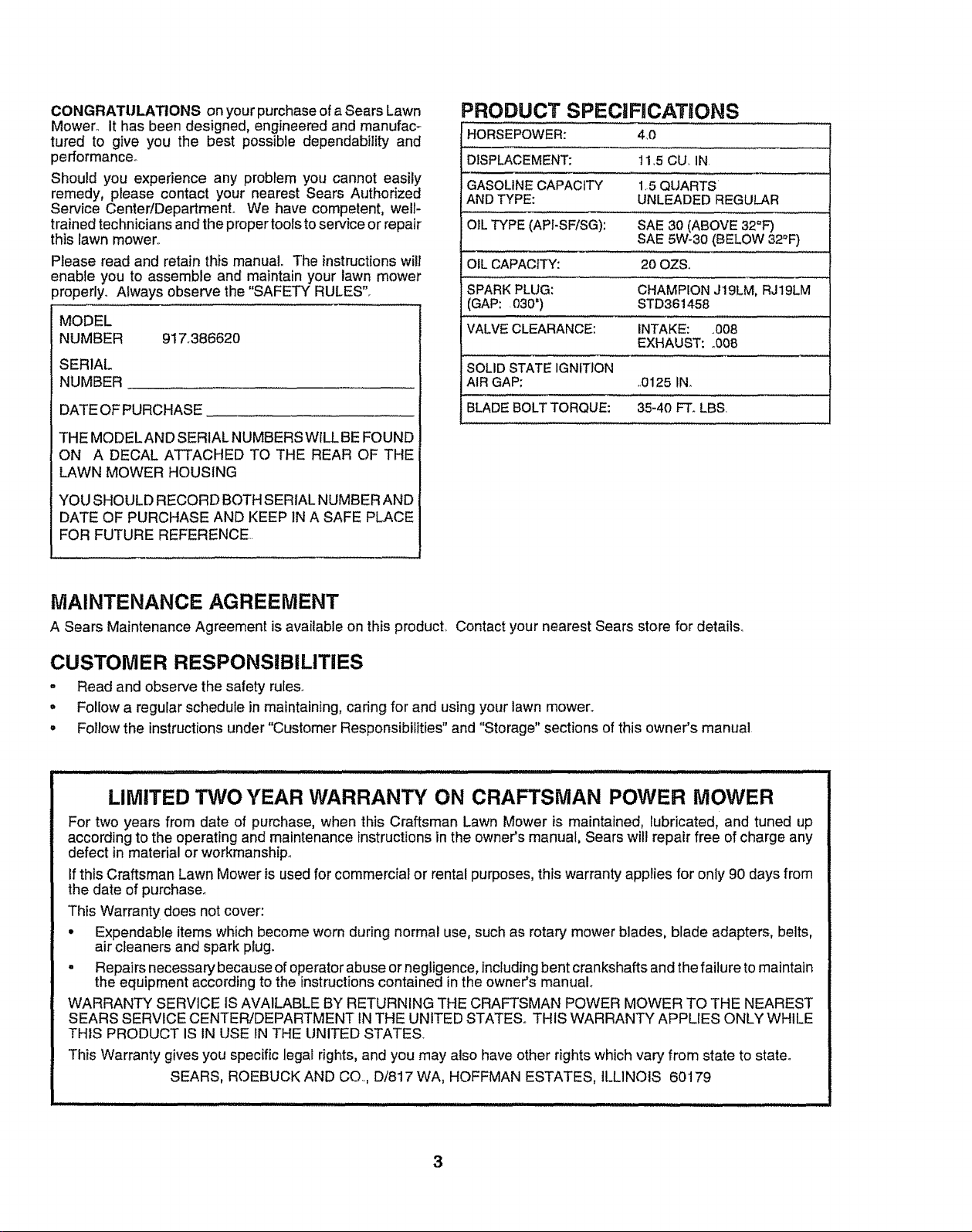
PRODUCT SPECiFiCATiONS
HORSEPOWER: 440
DISPLACEMENT: 11.5CU_IN
GASOLINE CAPACITY 15 QUARTS
ANDTYPE: UNLEADED REGULAR
OILTYPE(API-SFiSG): SAE 30 (ABOVE 32°F)
SAE 5W_30(BELOW32°F)
OILCAPACITY: 20 OZSo
SPARKPLUG: CHAMPIONJ19LM,RJ19LM
(GAP: .030") STD361458
VALVECLEARANCE: INTAKE: ..008
EXHAUST: _008
SOLID STATE IGNITION
AIR GAP: ,.0125IN_
BLADEBOLTTORQUE: 35-40 FT. LBS.
MAINTENANCE AGREEMENT
A Sears Maintenance Agreement is available on this product, Contact your nearest Sears store for details.
CUSTOMER RESPONSiBILITiES
• Read and observe the safety rules..
• Follow a regular schedule in maintaining, caring for and using your lawn mower°
,, Follow the instructions under "Customer Responsibilities" and "Storage" sections of this owner's manual
.............. H .................................................................
LIMITED TWO YEAR WARRANTY ON CRAFTSMAN POWER MOWER
For two years from date of purchase, when this Craftsman Lawn Mower is maintained, lubricated, and tuned up
according to the operating and maintenance instructions in the owner's manual, Sears will repair free of charge any
defect in material or workmanship_
If this Craftsman Lawn Mower is used for commercial or rental purposes, this warranty applies for only 90 days from
the date of purchase.
This Warranty does not cover:
• Expendable items which become worn during normal use, such as rotary mower blades, blade adapters, belts,
air cleaners and spark plug.
- Repairs necessary because of operator abuse or negligence, including bent crankshafts and the failure to maintain
the equipment according to the instructions contained in the owner's manual
WARRANTY SERVICE IS AVAILABLE BY RETURNING THE CRAFTSMAN POWER MOWER TO THE NEAREST
SEARS SERVICE CENTER!DEPARTMENT INTHE UNITED STATES_ THIS WARRANTY APPLIES ONLY WHILE
THIS PRODUCT IS IN USE IN THE UNITED STATES.
This Warranty gives you specific legal rights, and you may also have other rights which vary from state to state°
SEARS, ROEBUCK AND CO.., D/817 WA, HOFFMAN ESTATES, ILLINOIS 60179
3
Page 4
TABLE OF CONTENTS
i ii tJllU illllll ii
SAFETY RULES ............................................................ 2
PRODUCT SPEClRCATIONS ...................................... 3
CUSTOMER RESPONSIBILITIES ..................... 3, 11-13
WARRANT',( .................................................................. 3
ASSEMBLY' ................................................................... 6
OPERATION .................................................................. 8
MAINTENANCE SCHEDULE ..................................... 11
i n i Ill I I
INDEX
II Illll Illllll III ....
SERVICE AND ADJUSTMENTS ................................ 14
STORAGE ................................................................... 15
TROUBLESHOOTING ................................................. 21
REPAIR PARTS - LAWN MOWER ........................ 16-17
REPAIR PARTS - ENGINE .................................... 18-20
PARTS ORDERING/SERVICE ................................... 22
A
Accessories .................................... 5
Adjustments:
Carburetor _............................... 14
Engine Speed ................................14
Handle Height ............................ 14
Height of Cut .............................. 9
Air Filter:
Replacement ..................................13
Service ................................... 13
Assembly ............................................6
B
Blade:
Sharpening ..................................12
Replacement ...............................12
C
Controls:
Engine Zone Control ................. 9
Engine Speed Control ..................8
Operator Presence
Control Bar ...............................................8
Customer Responsibilities .....3, 11-13
Air Filter o....................................13
Blade Care/Replacement ........12
Engine ............................................................13
Lubrication ....................................13
Spark Plug ..................................13
Cutting Levels ..................................................9
E
Engine:
Air Filter .................................................13
Oil Change ........................................13
Oi! Level ........................................13
Oil Type ..............................................13
Starting ......................................................10
Stopping .......................................10
Storage ..........................................15
F
Fuel:
Capacity ...............................................3
Storage .................................................15
Type .............................................................9
H
Handle Adjustment:
Assembly ....................................6
Cutting Height ............................14
L
Lubrication:
Engine ............................................13
Lawn Mower .............................11
M
Maintenance Agreement ................ 3
Maintenance Schedule ....................11
Mowing Tips.........................................10
0
Oil:
Engine ..................................................13
Storage .............................................15
Operation:
Engine Control ................................9
Grass Catcher'. ................................9
Mower',...........................................9
Operator Presence
Control Bar ........................................9
Options:
Accessories .................................5
R
Repair'Parts:
Engine ...........................................18-20
Lawn Mower ............................16-17
Responsibilities, Customer .o3, 11-13
S
Safety Rules .........................................2
Service and Adjustments .................14
Carburetor, ...................................14
Engine Speed ......................... 14
Handle ......................................14
Spark Plug .................................... 13
Specifications ........................................................3
Speed Control:
Engine ............................................................14
Starting the Engine ..................................10
Stopping the Engine ...................... 10
Storage ................................................15
T
Trouble Shooting Chart ......................21
W
Warranty ...............................................3
4
Page 5
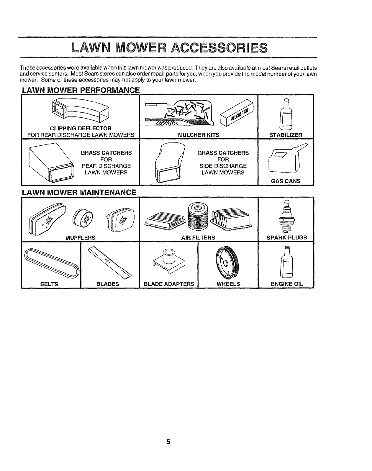
These accessories were available when this lawn mower was produced. They are alsoavailable at most Sears retail outlets
and service centers° Most Sears stores can also order repair parts for you, when you provide the model number of your lawn
mower., Some of these accessories may not apply to your lawn mower,
LAWN MOWER PERFORMANCE
A
CLIPPING DEFLECTOR
FOR REAR DISCHARGE LAWN MOWERS
MULCHER KITS
STABILIZER
GRASS CATCHERS
FOR
REAR DISCHARGE
LAWN MOWERS
LAWN MOWER MAINTENANCE
MUFFLERS
BELTS BLADES
GRASS CATCHERS
FOR
SIDE DISCHARGE
LAWN MOWERS
AIR FILTERS
BLADE ADAPTERS WHEELS
GAS CANS
SPARK PLUGS
ENGINE OIL
5
Page 6
...... i iiii1,1,1 ii ii i ii iiiii i H IIIIIIIIIIIIIII
ASSEMBLY
................................................ IIIII I I I I I II II IIIIIIIIIII IIIIIIIIII [111 II I[
Read these instructions and this manual in its entirety
before you attempt to assemble or operate your new lawn
mower. Your new lawn mower has been assembled atthe
factory with the exception of those parts left unassembled
for shipping purposes, All parts such as nuts, washers,
bolts, etc. necessary tocomplete the assembly have been
placed in the parts bag. To ensure safe and proper
operation of your lawn mower, all parts and hardware you
assemble must be tightened securely. Use the correct
tools as necessary to ensure proper tightness,
TO REMOVE
LAWN MOWER FROM
CARTON
• Remove loose parts included with mower',
• Cut down two end corners of carton and layend panel
down fiat°
• Remove all packing materials except padding between
upper and lowerhandle and padding holding operator
presence control bar to upper handle.
• Roll lawn mower out of carton and check carton thor-
oughly for additional loose parts.
HOWTO SET UPYOUR LAWN MOWER
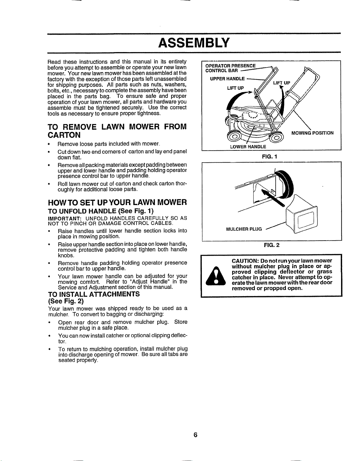
TO UNFOLD HANDLE (See Fig. 1)
IMPORTANT: UNFOLD HANDLES CAREFULLY SO AS
NOT TO PINCH OR DAMAGE CONTROL CABLES..
• Raise handles until lower handle section locks into
place in mowing position°
• Raise upper handle section intoplaceon lower'handle,
remove protective padding and tighten both handle
knobs.
• Remove handle padding holding operator presence
control bar to upper handle.
° Your lawn mower handle can be adjusted for your
mowing comfort. Refer to "Adjust Handle" in the
Service and Adjustment section of this manual.
TO INSTALL ATTACHMENTS
(See Fig, 2)
Your lawn mower was shipped ready to be used as a
rnulcher, To convert to bagging or discharging:
o Open rear door' and remove mulcher plug. Store
muicher plug in a safe place.
• You can now install catcher or optional dipping deftec-
toro
° To return to mulching operation, install mulcher plug
into discharge opening of mower,. Be sure all tabs are
seated properly_
OPERATOR PRESENCE
CONTROL BAR
UPPER HANDLE
LIFT UP
LOWER HANDLE
MULCHER PLUG
IIIIIIIIIIIIIIIIIII I I I IIL ILIIIIIII IIIIIIIIIIIIIII1 I LII II
CAUTION: Donot runyour lawn mower
proved clipping deflector or grass
catcher in place. Never attempt to op-
without mulcher plug in place or ap-
erate the lawn mower with the rear door
removed or propped open.
MOWING POSITION
FIG, 1
FIG. 2
6
Page 7
AI lILY
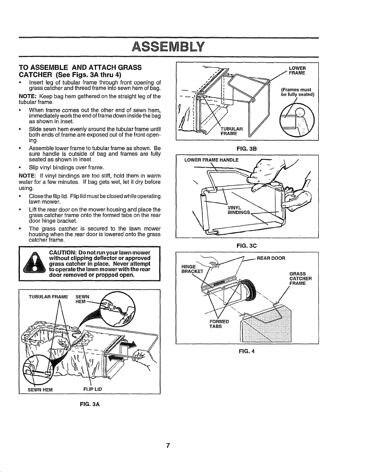
TO ASSEMBLE AND ATTACH GRASS
CATCHER (See Figs. 3A thru 4)
• Insert leg of tubular frame through front opening of
grass catcher and thread frame intosewn hem of bag.
NOTE: Keep bag hem gathered on the straight leg of the
tubularframe.=
• When frame comes out the other end of sewn hem,
immediately work the end offrame down insidethe bag
as shown in inset,,
° Slide sewn hem evenly around the tubular frame until
both ends of frame are exposed out of the front open-
ing
. Assemble lower frame to tubular frame as shown_ Be
sure handle is outside of bag and frames are fully
seated as shown in inset,
° Slip vinyr bindings over frame.
NOTE: If vinyl bindings are too stiff, hold them in warm
water for a few minutes., If bag gets wet, let it dry before
using.
• Close the flip lid,,Flip lid must be closed while operating
lawn mower°
° Lift the rear door on the mower housing and placethe
grass catcher frame onto the formed tabs on the rear
door hinge bracket°
o The grass catcher is secured to the lawn mower
housing when the rear door is lowered onto the grass
catcher frame,,
i ,,ll ......
_"2 "_ LOWER
t,,__ FRAME
l J!l
7"-°
FIG. 3B
LOWERFRAMEHANDLE
\
FIG. 3C
without clipping deflector or approved
_ CAUTION: Do not run your lawn mower
TUBULAR FRAME
SEWN HEM
grass catcher in place. Never attempt
to operate the lawn mower with the rear
door removed or propped open.
SEWN t
FLIP LID
FIG. 3A
BRACKET
REARDOOR
GRASS
CATCHER
FRAME
\
FORMED
TABS
FIG. 4
7
Page 8
OPERATION
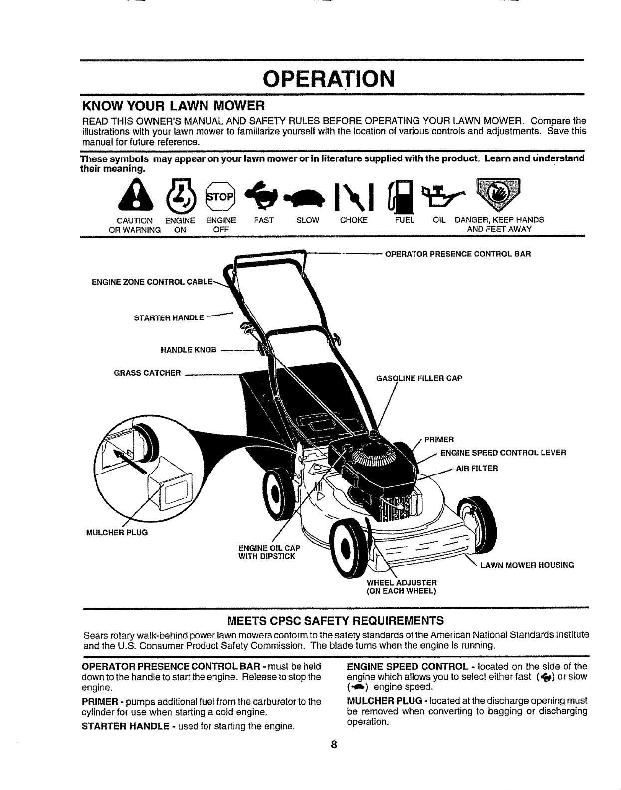
KNOW YOUR LAWN MOWER
READ THIS OWNER'S MANUAL AND SAFETY RULES BEFORE OPERATING YOUR LAWN MOWER_ Compare the
illustrations with your' lawn mower' to familiarize yourself with the location of various controls and adjustments. Save this
manual for future reference.
These symbols may appear on your lawn mower or tn literature supplied with the product Learn and Understand
their meaning.
CAUTION ENGINE ENGINE FAST SLOW CHOKE FUEL OIL DANGER, KEEP HANDS
OR WARNING ON OFF AND FEET AWAY
OPERATOR PRESENCECONTROLBAR
ENGINE
HANDLE KNOB_
GRASS CATCHER
MULCHER PLUG
ENGINE OIL CAP
WITH DIPSTICK
GASOLINE FILLER CAP
ENGINE SPEED CONTROL LEVER
FILTER
LAWN MOWER HOUSING
WHEEL ADJUSTER
(ON EACH WHEEL)
MEETS CPSC SAFETY REQUIREMENTS
Sears rotarywalk-behindpower lawn mowers conformtothe safety standards of theAmerican NationalStandards Institute
and the U,S, Consumer ProductSafety Commission. The blade turnswhen the engine is running,
liE I IIII II Illllllllllll II ............................
OPERATOR PRESENCE CONTROL BAR - must be held
downto the handle to start the engine, Release tostop the
engine.
PRIMER - pumpsadditional fuel from the carburetortothe
cylinder'for use when startinga coldengine,,
STARTER HANDLE - usedfor starting the engine,,
ENGINE SPEED CONTROL - located on the side of the
engine which allows you to select either fast (,#j_)or slow
(-_) engine speed.
MULCHER PLUG - located at the discharge opening must
be removed when converting to bagging or discharging
operation.
8
Page 9
H,,i,i ,11...... i ,,,_l illl,i......... M''I .....
OPERATNON
........ ......ll,,,i ,,i, _1 _ ,,,llll i ii .........................
The operation of any lawnmower can result in foreign objects thrown into the eyes, which can
result insevere eye damage° Always wear safety glasses or eye shields while operating your
lawn mower or performing any adjustments or repairs. We recommend a wide vision safety
.................. ,,ir,,11.,, i,ii,i i • .........
HOW TO USE YOUR LAWN MOWER
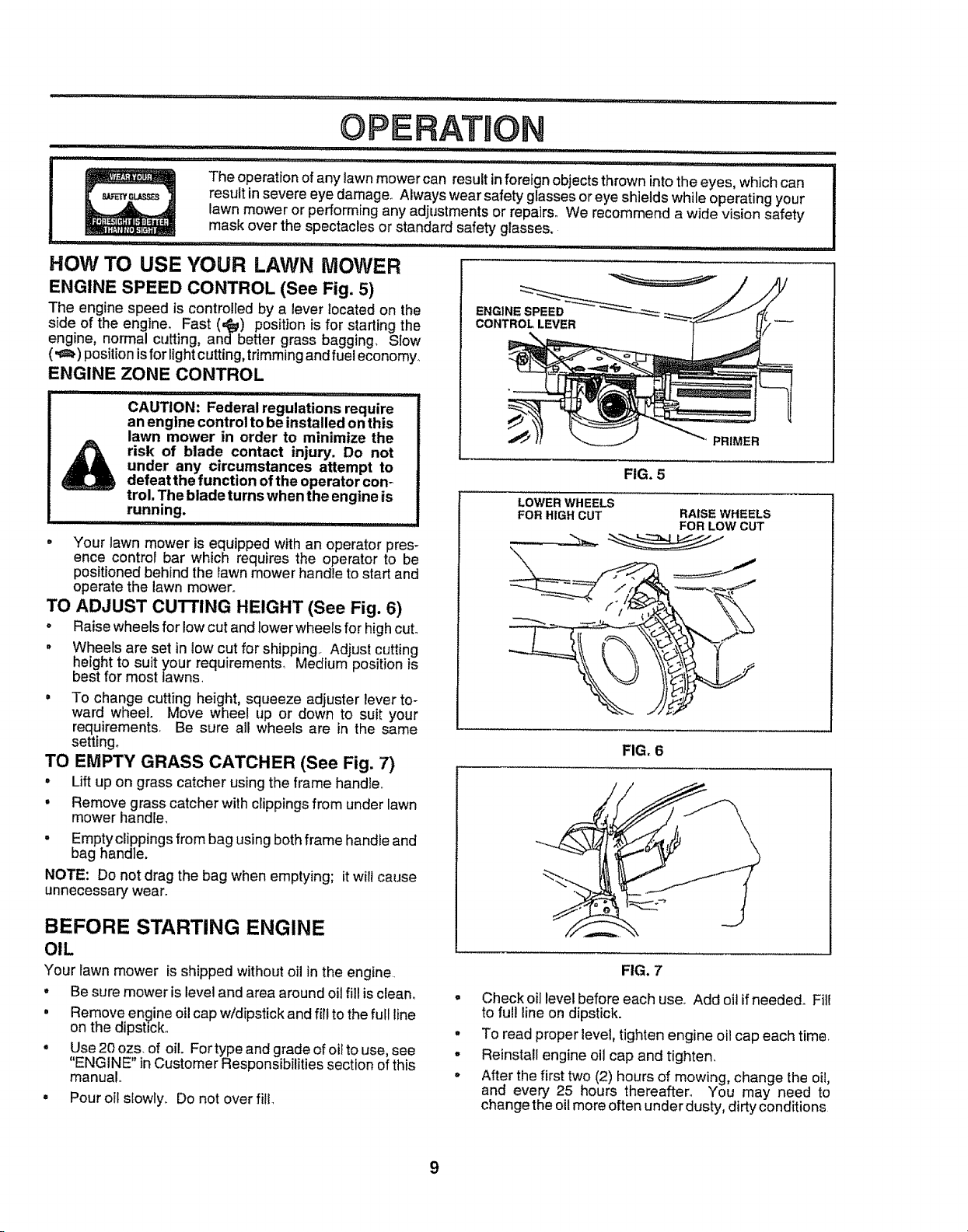
ENGINE SPEED CONTROL (See Fig, 5)
The engine speed is controlledby a lever located on the
side of the engine, Fast (,#_) positionis for starting the CONTROLLEVER
engine, normal cutting, and better grass bagging, Slow
('_) position isfor lightcutting, trimming and fueleconomy,,
ENGINE ZONE CONTROL
CAUTION: Federal regulations require
an engine control to be installed on this
lawn mower in order to minimize the ,_
risk of blade contact injury. Do not
under any circumstances attempt to
defeat the function of the operator con-
trol, The blade turns when the engine is
running.
II....
• Your lawn mower is equipped with an operator pres-
ence control bar which requires the operator to be
positioned behind the lawn mower handle to start and
operate the lawn mower°
TO ADJUST CUTTING HEIGHT (See Fig. 6)
• Raise wheels for low cut and lower wheels for high cuL
o Wheels are set in towcut for shipping, Adjust cutting
height to suit your requirements, Medium position is
best for most lawns,
o To change cutting height, squeeze adjuster lever to-
ward wheel. Move wheel up or down to suit your
requirements, Be sure all wheels are in the same
setting_
TO EMPTY GRASS CATCHER (See Fig. 7)
• Lift up on grass catcher using the frame handle,,
, Remove grass catcher with clippings from under lawn
mower handle,
• Empty clippings from bag using both frame handle and
bag handle.
NOTE: Do not drag the bag when emptying; itwilt cause
unnecessary wear.
mask over the spectacles or standard safety glasses.
LOWER WHEELS
FOR HIGH CUT RAISE WHEELS
PRIMER
FIG, 5
FOR LOW CUT
FIG, 6
BEFORE STARTING ENGINE
OIL
Your lawn mower isshipped without oil inthe engine,
. Be sure mower is leveland area around oil fill is clean.
• Remove engine oil cap w/dipstick and fill to the full line
on the dipstick,,
° Use 20 ozs. of oil. Fortype and grade of oil to use, see
"ENGINE" inCustomer Responsibilities section of this
manual,,
• Pour oil s{owly,, Do not over flit,
FIG. 7
• Check oil level before each use. Add oitif needed. Fil{
to ful! line on dipstick.
° To read proper level, tighten engine oil cap each time
° Reinstall engine oil cap and tighten_
o After the first two (2) hours of mowing, change the oii,
and every 25 hours thereafter_ You may need to
change the oilmore often under dusty, dirtyconditions
Page 10
OPERATION
GAS
• Fill fuel tank° Use fresh, clean, regular unleaded
gasoline with a minimum of 87 octane_ (Use of leaded
gasoline will increase carbon and lead oxide deposits
and reduce vatve life) Do not mix oil with gasoline.
Purchase fuel in quantities that can be used within 30
days to assure fuel freshness,
WARNING: Experience indicates that alcohol blended
fuels (called gasohol or using ethanol or methanol) can
attract moisture which leads to separation and formation of
acids during storage. Acidic gas can damage the fuel
system of an engine while in storage. To avoid engine
problems, the fuel system should be emptied before stor-
age of 30 days or longer° Drain the fuel tank, start the
engine and let it run until fuel lines and carburetor are
empty. Use fresh fuel next season° See Storage instruc-
tions for additional information, Never use engine or'
carburetor cleaner products in fuel tank or permanent
damage may occur°
TO START ENGINE
• To start acold engine, push primerfive (5) times before
trying to start, Use afirm push. This step isnot usually
necessary when starting an engine which hasalready
run for a few minutes°
• Push engine speed control leverto fast (,_) position.
o Hold operator presence control bar down to thehandle
and pull starter handle quickly° Do not allow starter
ropeto snap back.
• To stop engine, releaseoperator presence control bar.,
NOTE: In cooter weather it may be necessary to repeat
priming steps In warmer weather over priming may cause
flooding and engine will not start_ If you do flood engine,
wait a few minutes before attempting to start and do not
repeat priming steps.
MOWING TIPS
o Under certain conditions, such asvery tallgrass, itmay
be necessary to raise the height of cut to reduce
pushing effort andto keep from overloading the engine
and leaving clumps of grass clippings.
• For extremely heavy cutting, reduce the width of cut
and raise the rear of the lawn mower housing one (!)
wheel adjuster setting higher than the front for better
discharge of grass.
• For better grass bagging and most cutting conditions,
the engine speed should be set in the fast (,_) posi-
tion,
• When using a rear discharge lawn mower' in moist,
heavy grass, clumps of cut grass may not enter the
grass catcher Reduce ground speed (pushing speed)
and/or runthe lawn mower over theareaa second time_
• Ifa trail ofgrass clippings isleftonthe rightside ofa rear
discharge lawn mower, mow in a clockwise direction
with asmall overlap to collect the clippings on the next
pass
° Keep top of engine around starter clear and clean of
grass clippings and chaff. This will help engine air flow
and extend engine life.
MAX t/3
FIG. 8
• Pores incloth grass catchers can become filled withdirt
and dust with use and catchers willcollect lessgrass.
To prevent this, regularly hose catchers off with water
and let dry before using
MULCHING MOWING TIPS
IMPORTANT: FOR BEST PERFORMANCE, KEEP
MOWER HOUSING FREE OF BUILT-UP GRASS AND
TRASH, CLEAN UNDERSIDE OF MOWER HOUSING
AFTER EACH USE, SEE "CLEANrNG" IN CUSTOMER
RESPONSIBILITIES SECTION OF THIS MANUAL,
• The special mulching blade will recut the grass clip-
pings manytimes and reduce them in size so that as
theyfall ontothe lawn they willdisperse intothe grass
and not be noticed° Also, the mulched grass will
biodegrade quickly to provide nutrients for the lawn.
Always mulch with your' highest engine (blade) speed
as this will provide the best recutting action of the
blades.
° Avoid cutting your lawnwhen itiswet, Wet grass tends
to form clumps andinterferes with the mulching action.
The best time to mow your lawn isthe early afternoon_
At this time the grass has dried and the newly cut area
will not be exposed to the direct sun.
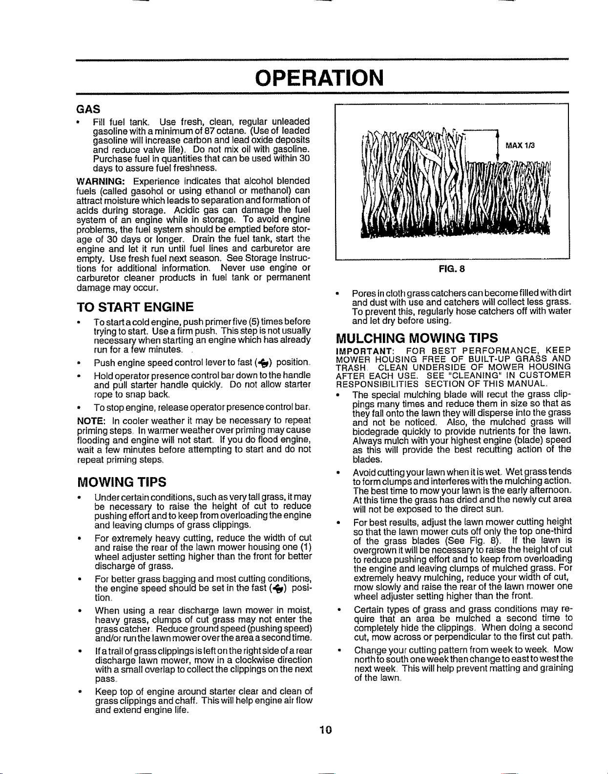
° For best results, adjust the lawn mower cutting height
so that the lawn mower cuts off only the top one-third
of the grass btades (See Fig. 8). If the lawn is
overgrown itwillbe necessary to raise the height ofcut
to reduce pushing effort and to keep from overloading
the engine and leaving clumps of mulched grass. For
extremely heavy mulching, reduce your width of cut,
mow slowly and raise the rear of the lawn mower one
wheel adjuster setting higher than the fronL
• Certain types of grass and grass conditions may re-
quire that an area be mulched a second time to
completely hide the clippings. When doing a second
cut, mow across or perpendicular to the first cut path.
° Change your cutting pattern from weekto week. Mow
north tosouth one week then change to east to west the
next week, This will help prevent matting and graining
of the lawn,
10
Page 11
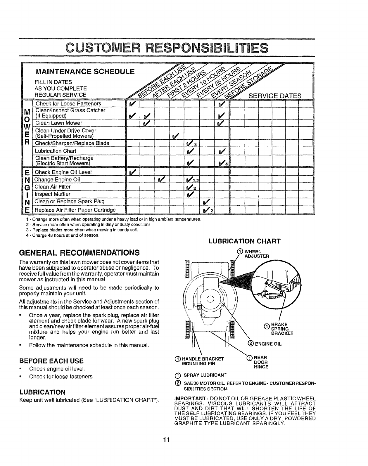
Check forLoose Fasteners V_'
Clean/Inspect Grass Catcher
(if Equipped) _/
Ctean Lawn Mower
Clean Under Drive Cover
(Self-Propelled Mowers) _#'
ChecWSharpen/Replace Blade _ _ 3
Lubrication Chart
Clean'"Battery/Recharge
(Electric Start Mowers) ................................_........-,_
Check Engine Oil Level _'
E
Clean Air Filter . M/2
!
Inspect Muffler ............
Clean or Replace Spark Plug
N
E i Replace Air Filter Paper Cartridge
I - Change more often when operating under a heavy load or in high ambient lemperatures
2 - Service more often when operaltng in dirty ordusly conditions
3 - Replace blades more often when mewing insandy soil,
4 - Charge 48 hours at end of season
GENERAL RECOMMENDATIONS
The warranty onthis lawn mower does notcover items that
have been subjected to operator abuse or negtigence_ To
receive full value fromthe warranty, operator mustmaintain
mower as instructed in this manual.,
Some adjustments wilt need to be made periodically to
properly maintain your unit°
All adjustments in the Service and Adjustments section of
this manual should be checked at least once each season.
o Once a year, replace the spark plug, replace air filter
element and check blade for wear,. A new spark piug
and clean/new air filter element assures proper air-fuel
mixture and helps your engine run better and last
longer,,
= Follow the maintenance schedule in this manual..
LUBRICATION CHART
WHEEL
ADJUSTER
(_)BRAKE
(_ ENGINE OIL
SPRING
BRACKET
BEFORE EACH USE
• Check engine oil level..
° Check for loose fasteners.
LUBRICATION
Keep unit well lubricated (See "LUBRICATION CHART")..
_'_HANDLEBRACKET REAR
MOUN_NGPIN DOOR
(_ SPRAY LUBRICANT
(_) SAE30 MOTOR OIL REFER TO ENGINE- CUSTOMER RESPON-
SIBILITIES SECTION,,
IMPORTANT: DO NOT OIL OR GREASE PLASTIC WHEEL
BEARINGS, VISCOUS LUBRICANTS WILL ATTRACT
DUST AND DlRT THAT WILL SHORTEN THE LIFE OF
THE SELF LUBRICATING BEARINGS. IF YOU FEELTHEY
MUST BE LUBRICATED, USE ONLYA DRY, POWDERED
GRAPHITE TYPE LUBRICANT SPARINGLY°
HINGE
11
Page 12
.............................. lib L
.................. i ILl lllJllUlllllll
........................... ,,, ,, ,, ,,,,,,,, ,,,,,,,
CUSTOMER NSIBILITIES
LAWN MOWER
Always observe safety rules when performing any mainte-
nance.
TIRES
• Keep tires free of gasoline, oil, or insect control chemi-
cals which can harm rubber.
• Avoid stumps, stones, deep ruts, sharp objects and
other hazards that may cause tire damage.
BLADE CARE
Forbest results, mower blade must be kept sharp. Replace
bent or damaged blades.
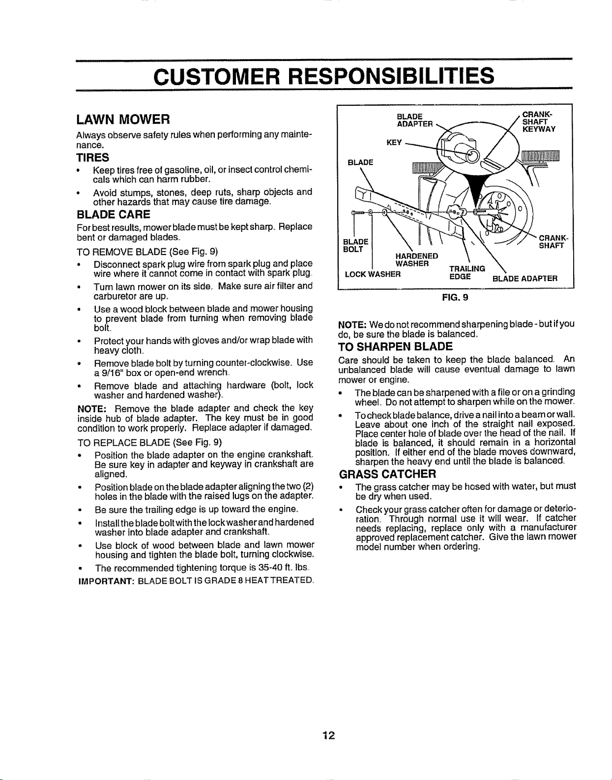
TO REMOVE BLADE (See Fig. 9)
• Disconnect spark plug wire from spark plugand place
wire where it cannot come incontact with spark plug.
• Turn lawn mower on its side. Make sure air filter and
carburetor are up.
• Use a wood block between blade and mower housing
to prevent blade from turning when removing blade
bolt.
- Protect your hands with gloves and/or wrap blade with
heavy cloth.
, Remove blade bolt by turning counter-clockwiseo Use
a 9/16" box or open-end wrench.
• Remove blade and attaching hardware (bolt, lock
washer and hardened washer)°
NOTE: Remove the blade adapter and check the key
inside hub of blade adapter. The key must be in good
condition to work properly. Replace adapter if damaged°
TO REPLACE BLADE (See Fig. 9)
• Position the blade adapter on the engine crankshaft.
Be sure key in adapter and keyway in crankshaft are
aligned.
• Position blade on the blade adapter aligning the two (2)
holes in the blade with the raised lugs on the adapter.
• Be sure the trailing edge is up toward the engine.
- Instaltthe blade bolt with the lockwasher andhardened
washer into blade adapter and crankshaft.
° Use block of wood between blade and lawn mower
housing and tighten the blade bolt, turning clockwise.
• The recommended tightening torque is 35-40 ftoIbs..
IMPORTANT: BLADE BOLT ISGRADE 8 HEATTREATED.
BLADE .CRANK_
KEY
BLADE
HARDENED
WASHER
LOCK WASHER EDGE BLADE ADAPTER
TRAILING
FIG. 9
SHAFT
KEYWAY
CRANK-
SHAFT
NOTE: Wedonot recommend sharpening blade -but if you
do, be sure the blade is balanced_
TO SHARPEN BLADE
Care should be taken to keep the blade balanced. An
unbalanced blade will cause eventual damage to lawn
mower'or engine.
• The blade can be sharpened with afile oron a gdnding
wheel. Do notattempt to sharpen while on the mower.
° To check blade balance, drive a nail into a beam or wail
Leave about one inch of the straight nail exposed.
Place center hole of blade over the head of the nail If
blade is balanced, it should remain in a horizontal
position. If either end of the blade moves downward,
sharpen the hea_r_end until the blade is balanced.
GRASS CATCHER
• The grass catcher may be hosed with water, but must
be dry when used.
- Check your grass catcher often for damage ordeterio-
ration. Through normal use it will wear. If catcher
needs replacing, replace only with a manufacturer
approved replacement catcher. Give the lawn mower
model number when ordering°
12
Page 13

CUSTOMER
a .................
RESPO mLmTUE$
ENGINE
LUBRICATION
Use only high quality detergent oil ratedwith API service
classificationSF orSG Select theoil'sSAEviscositygrade
according to your expected operatingtemperature,
SAE VISCOSITY GRADES
t
_F -20" 0 ° 30° 32? 40' 60• _0 _ _00"
°c-_o"............:aO"..............-1o,....o' _oo 20, _o, 40,
TEMPERATURE RANGE ANT1CIPATEO BEFORE NEXTOIL CHANGE
CONTAINER
NOTE: Although multi-viscosity oils (5W30, 10W30 etc.)
improve starting in cold weather, these multi-viscosity oils
will result in increased oil consumption when used above
32°F. Check your engine oil level more frequently to avoid
possible engine damage from running low on oil,
Change the oil after the first two hours of operation and
every 25hours thereafter or at least once ayear ifthe lawn
mower is not used for 25 hours in one year,.
Check the crankcase oil level before starling the engine
and after each five (5) hours of continuous use.,Tighten oil
plug securely each time you check theoil level,
TO CHANGE ENGINE OIL (See Fig. 10)
NOTE: Before tipping lawn mower to drain oil, drain fuel
tank by running engine until fuel tank is empty_
. Disconnect spark pfug wire from spark plugand place
wire where it cannot come in contact with spark plug,
• Remove engine oil cap; layaside on a clean surface,
• Tip lawn mower on its side and drain oil into a suitable
container° Rock tawn mower back andforthto remove
any oil trapped inside of engine
• Wipe off any spilled oii on tawn mower and on side of
engine.,
, Fill engine with oil. Fi!l onty to the "FULL" line on the
dipstick,. DO NOT OVER FILL.,
• Replace engine oit cap.
• Reconnect spark plug wire to spark plug,,
AIR FILTER
Your engine will not run properly and may be damaged by
using a dirty air filter.
Replace the air filter every year, more often if you mow in
very dusty, dirty conditions_ Do not wash air filter.,
TO CHANGE AIR FILTER (See Fig,,1t)
° Remove the air filtercover by turning counterclockwise
to the stop and pull away from collar,,
° Remove filter from inside of cover,
° Clean the inside of the cover and the collar to remove
any dirt accumulation,
° Insert new filter into cover_,
° Put air filter cover and filter into collar aligning the tab
with the slot,
° Push in on cover and turn clockwise to tighten.,
FIG. 10
COLLAR
COUNTER-
CLOCKWISE
SLOT
AIR FILTER COVER
FIG. 11
TO REMOVE
4CLOCKWISE
TO TIGHTEN
MUFFLER
inspectand replace corroded muffler as it could create a
fire hazard and!or damage,,
SPARK PLUG
Change your spark plug each year to make your engine
start easier and runbetter. Set spark plug gap at ,030 inch,
CLEANING
IMPORTANT: FOR BEST PERFORMANCE, KEEP
MOWER HOUSING FREE OF BUILT-UP GRASS AND
TRASH, CLEAN UNDERSIDE OF MOWER HOUSING
AFTER EACH USE,
Turn lawn mower on its side., Make sure air filter and
carburetor are up., Clean the underside of your Iawn
mower by scraping to remove build-up of grass and
trash°
• Clean engine often to keep trash from accumulating. A
ctogged engine runs hotter and shortens engine life_,
° Keep finished surfaces and wheels free of all gasoline,
oil, etc
- We DONOT recommend using a garden hose toclean
lawn mower unless the electrical system, muffler, air
filter and carburetor are covered to keep water out,
'13
Water in engine can result in shortened engine life
Page 14

SERVICE AND ADJUSTMENTS
illllllllllll iilll u i lll ii ii illllllllllllllllll ,,H I ...........................
• Release control bar.
• Make sure the blade and all moving parts have completely stopped.
CAUTION: BEFORE PERFORMING ANY SERVICE OR ADJUSTMENTS: I
° Disconnect spark plug wire from spark plug and place where it cannot come in contact with plug.,
"' .......................................... _: .... ,iHii =l=l=l=l=l==ll=i i
LAWN MOWER
TO ADJUST CUTTING HEIGHT
See "TO ADJUST CUTTING HEIGHT" in the Operation
section of thismanual.
REAR DEFLECTOR
The rear deflector, attached between the rear wheels of
your lawn mower, is provided to minimizethe possibility
that objects willbe thrown out the rear ofthe lawn mower
intothe operator'smowing position.
if the rear deflector becomes damaged, it should be re-
placed
TO ADJUST HANDLE (See Figs. 12 Thru 14)
Your lawn mower handle can be raised or loweredforyour
mowing comfort. Four (4) positions are available: high,
medium high, medium low and low. Handles are shipped
mounted in the medium low position.
° To change from medium lowto medium high position,
the upper and lower handle sections will have to be
turned over (See Fig° 12B)
° Remove the cable clips.
° Remove the controls and operator presence control
bar from the upper handle.
• Remove the starter rope guide from the lower handle°
° Remove hairpin cotters.
• Disconnect the lower handle from the handle brackets
(See Fig. 14).
° Turn the handle over and reassemble the hairpin
cotters that have been removed_
. Reassemble the starter rope guide.
- Reassemble the controls and the operator presence
control bar to the upper handle.
CAUTION: The operator presence con- !
_trol bar must pivot freely to permit blade
° To change from medium low to high position only the
upper handle section will have to be turned over (See
Fig. 13A)
° To change from medium low to low position,only the
lower handle section will have to be turned over (See
Fig_13B)
ENGINE
CARBURETOR
Your carburetor has a nomadjustabIe fixed main jet for
mixture control. If your engine does not operate property
due to suspected carburetor problems, take your lawn
mower to an authorized service center for repair or adjust-
ment
brake engagement when control bar is
released. Do not over tighten the fas-
teners holding the controls to the up-
.....Per handle. ,..............
SHIPPING POSITION
MEDIUM LOW
FIG. 12A FIG. 12B
FIG. 13A FIG. 13B
SQUEEZE
TO REMOVE
MEDIUM HIGH
LOWER HANDLE
I
HAIRPIN CLIP
FIG. 14
ENGINE SPEED
Your engine speed has been factoryseL Do not attempt
to increase engine speed or itmay result in personal injury.
Ifyou believe that the engine is runningtoo fast ortoo slow,
take your lawn mower to an authorized service center for
repair and adjustmenL
14
LOW
HANDLE
BRACKET
Page 15

Immediately prepare your lawn mower for storage at the
end of the season or ifthe unitwill not be used for 30 days
or more,
LAWN MOWER
When lawn mower isto be stored for aperiod of time, clean
it thoroughly, remove all dirt, grease, leaves, etco Store in
a clean, dry area°
o Clean entire lawn mower (See CLEANING Jnt e
Customer Responsibilities section of this manual).
. Lubricate as shown in the Customer Responsibilities
section of this manual,,
o Be sure that all nuts, bolts, screws, and pins are
securely fastened. Inspect moving parts for damage,
breakage and wear. Replace if necessary,,
o Touch up at! rusted or chipped paint surfaces; sand
lightly before painting_
HANDLE (See Fig. 15)
You can fold your lawn mower handle for storage,
° Squeeze the bottom ends of the lower handle toward
each other until the lower handle clears the handle
bracket, then move handle forward°
= Loosen upper handle mounting bolts enough to allow
upper handle to be folded back.
IMPORTANT: WHEN FOLDING THE HANDLE FOR
STORAGE OR TRANSPORTATION, BE SURE TO FOLD
THE HANDLE AS SHOWN OR YOU MAY DAMAGE THE
CONTROL CABLES.
° When setting up your handle fromthe storage position,
the lower handle will automatically lock intothe mowing
position°
* II ii. h
LOWER HANDLE
HANDLE
BRACKET
ENGINE
FUEL SYSTEM
IMPORTANT: IT IS IMPORTANT TO PREVENT GUM
DEPOSITS FROM FORMING IN ESSENTIAL FUEL
SYSTEMPARTSSUCHASCARBURETOR, FUELFILTER,
FUEL HOSE, OR TANK DURING STORAGE. ALSO,
EXPERIENCE tNDICATES THAT ALCOHOL BLENDED
FUELS (CALLED GASOHOL OR USING ETHANOL OR
METHANOL) CAN ATTRACT MOISTURE WHICH LEADS
TO SEPARATION AND FORMATION OF ACIDS DURING
STORAGE. ACIDIC GAS CAN DAMAGE THE FUEL
SYSTEM OF AN ENGINE WHILE IN STORAGE_
. Drain the fuel tank.
= Start the engine and let it run until the fuel lines and
carburetor are empty,
° Never useengine orcarburetorcleaner products inthe
fuel tank or permanent damage may occur.
= Use fresh fuel next season.
NOTE: Fuel stabilizer is an acceptable alternative in
minimizing the formation of fuel gum deposits during stor-
age. Add stabilizer to gasoline in fue! tank or storage
container° Always follow the mix ratio found on stabilizer
container. Run engine at least 10 minutes after adding
stabilizerto allowthe stabilizer toreach the carburetor. Do
notdrain the gas tank and carburetor ifusing fuel stabilizer°
ENGINE OIL
Drain oil (with engine warm) and replace with clean engine
oiL (See "ENGINE" in the Customer Responsibilities
section of this manual),
CYLINDER
= Remove spark plug,
• Pour one ounce (29 ml) of oil through spark plug hole
into cylinder
• Pull starter handle slowly a few times to distribute oil.
° Replace with new spark plug,
SQUEEZETO
FOLD
OPERATOR PRESENCE
LOWER HANDLE
FIG. 15
HAIRPIN
COTTER
/_ FOLD BACKWARD
MOWING
POSITION
OTHER
° Do not store gasoline from one season to another,
• Replace your gasoline can if your can starts to rust
Rust and/or dirt in your gasoline will cause problems.,
- If possible, store your unit indoorsand cover it togive
protection from dust and dirt.
- Cover your unit with a suitable protective cover that
does not retain moisture Do not use plastic. Plastic
cannot breathe which allows condensation toform and
will cause your unit to rust,
IMPORTANT: NEVER COVER MOWER WHILE ENGINE
AND EXHAUST AREAS ARE STILL WARM,
......................... u i, UUlU
with gasoline in the tank inside abuild-
ing where fumes may reach an open
I_ CAUTION: Never storethe lawn mower
15
flame or spark. Allow the engine to
cool before storing in any enclosure.
Page 16

REPAIR PARTS
t
\
ROTARY LAWN MOWER - - MODEL NO. 917.386620
..,.L
O3
57
12
58
7
17
35
\
28
t 8 23
24
32 33
37
43
42
43
4O
39
37
44
25
32
23,
"\
36 38
39
40
37
43
40
38
39
43
5O
38
39
Page 17

REPAIR PARTS
ROTARY LAWN MOWER - - MODEL NO. 917.386620
_.J_
,.q
KEY PART
NO. NO,
! 86902
2 133088X479
3 150424
4 132001
5 151516X479
6 STD541425
7 131959
8 151517
9 51793
10 136376
!1 130861
12 74350424
13 750097
14 850733X004
15 735104OO
17 147613
18 700357)(479
19 150050
21 54583
22 700063)(479
23 68652
24 700363X479
25 144875X479
26 140657
28 151512X479
29 151511X479
31 150078
32 700325X007
33 146630
34 128415
35 87877
DESCRIPTION
Control Bar
Upper Handle
Mulcher Plug
Rope Guide
Lower Handle
Locknut 1/4-20
Handle Bolt
Cable Clip
Hairpin Cotter
Handle Knob
Engine Zone Control Cable
Hex Head Bolt 1/4-20 x !-1/2
Hex Washer Head Screw 10-24 x 1/2
Up-Stop Bracket
Keps Locknut 1/4-20
Rear Door Assembly Kit
Back Plate
Self Tapping Screw 10-24 x 5/8
Hex Head Tapping Screw 1/4-20 x 1/2
Rear Baffle
Hinge Screw 1/4-20 x !-1/4
Side Baffle
Discharge Baffle
Rear Deflector
Handle Bracket Assembly (Left)
Handle Bracket Assembly (Right)
Screw 5/16-18 x 3/4
Wheel Adjusting Bracket
Spacer
Pop Rivet
Selector Knob
KEY PART DESCRIPTION
NO. NO.
36 70033tX004
37 145935X004
38 62335
39 142748
40 146248
42 83923
43 77400
44 85463
45 150406
46 48395
47 751592
50 700938X479
51 851084
52- 850263
53 851074
54 145106
55 850977
56 144748
57 149844
58 152709
59 144747
-- 153511
Selector Spring
Axle Arm Assembly
Betleville Washer
Shoulder Bolt
Wheel and Tire Assembly
Hex Flange Locknut
Hubcap
Danger Decal
Hex Head Thread Roiling Screw 3/8-16 x t
Lawn Mower Housing (tncl, Key #18, 22, 24, 44, 50)
Locknut 3/8-16
Front Baffle
Hex Head Machine Screw 3/8-24 x 1-3/8 (Grd. 8)
Helical Lockwasher 3/8
Washer
Blade 20"
Blade Adapter
Tube Frame
Grass Bag
Engine - Craftsman Model No.143.964010
Throat Frame
Owner's Manual
Available accessories not included with lawn mower:
71 33303 Clipping Deflector
7_!33723 Hi-Wheel Kit
7_!33623 Gas Can (2.5 gal.)
7_1_33500 Fuel Stabilizer
71 33300 SAE 30W Oil (20 oz.)
7"133417 Dust Shield
7"133316 Mower Cover
Page 18

CRAFTSMAN 4-CYCLE ENGINE
i,ilillllll.....................................
101
12s \
120
119
MODEL NUMBER 143.964010
I'11111111I I III '1 II IIII
O-31OK
298
!
I
2O4
182
1W
?
178
18
Page 19

CRAFTSMAN 4=CYCLE ENGINE MODELNUMBER143.964010
REF PART REF PART
NO. NO. DESCRIPTION NO. NO. DESCRIPTION
1 36774 Cylinder (Incl. 2 & 20) 174 30200 Screw, '10-24 x 9/16"
2 26727 Dowel Pin 178 29752 Nut & Lock Washer, 1/4-28
6 33734 Breather Element 182 6201 Screw, 1/4-28 x 7/8"
7 36557 Breather Ass'yo (Incl. 6 & 12A) t84 26756 * Carburetor To ]ntake Pipe Gasket
12 36775 Breather Tube 185 36785 Intake Pipe
12A 36558 Breather Cover & Tube (lncL 12B) 186 34358 Governor Link
12B 36694 Breather Tube Elbow 189 650839 Screw, 1/4-20 x 3/8"
14 28277 Washer 191 36559 SoE. Brake Bracket (Incl. 195)
15 30589 Governor Rod (Incl. 14) t95 610973 Terminal
16 34839A Governor Lever 200 35727 Control Bracket (lncL 202 thru 205)
17 31335 Governor Lever Clamp 202 36482 Compression Spring
18 650548 Screw, 8-32 x 5/16" 203 3!342 Compression Sprin,,g
19 36281 Extension Spring 204 650549 Screw, 5-40 x 7/16
20 32600 Oil Seal 205 650777 Screw, 6-32 x 21/32"
30 36793 Crankshaft 207 34336 Throttle Link
40 40004 Piston, Pin & Ring Set (Std,) 209 30200 Screw, 10-24 x 9/16"
40 40005 Piston, Pin & Ring Set(o010" OS) 215 32410 Control Knob 1"
41 36070 Piston & Pin Ass y. (Std.) (IncL 43) 223 650451 Screw, 1/4-20 x
41 36071 Piston & Pin Ass'y. 224 36786 * Intake Pipe Gasket
41 36072 Piston & Pin Ass'y. 239 34338 * Air Cleaner Gasket
42 40006 Ring Set (Std.) 245 35066 Air Cleaner Filter
42 40007 Ring Set (.010" OS) 250 35065 Air Cleaner Cover
43 20381 Piston Pin Retaining Ring 260 36794 Blower Housing ,
45 36777 Connecting Rod Ass'yo (IncL 46) 261 30200 Screw, 10-24 x 9/16'
46 32610A Connecting Rod Bolt 262 650831 Screw, !/4-20 x 1/2"
48 27241 Valve Lifter 275 36790 Muffler (Incl. 277)
50 36778 Camshaft (MCR) 277 650988 Screw, 1/4-20 x 2-5/16"
52 29914 Oil Pump Ass'y. 285 35000A Starter Cup
69 35261 * Mounting Flange Gasket 287 650926 Screw, 8-32 x 21/64"
70 34311D Mounting Flange (Incl. 72 thru 83) 290 30705 Fuel Line
72 36083 Oil Drain Plug 292 26460 Fuel Line Clamp
75 27897 Oil Seal 298 28763 Screw, 10-32 x 35/64"
80 30574A Governor Shaft 300 34369B Fuel Tank (incl. 292 & 301)
81 30590A Washer 301 36246 Fuel Cap
82 30591 Governor Gear Ass'y_ (tncL 81) 305 35647 Oil Fill Tube
83 30588A Governor Spool 306 34265 * "O"-Ring
86 650488 Screw, 1/4-20 x 1-1/4" 307 35499 "O"-Ring
89 611004 Flywheel Key 309 650562 Screw, 10-32 x 1/2"
90 611t12 Flywheel 310 35648 Dipstick
92 650815 Belleville Washer 313 34080 Spacer
93 650816 Flywheel Nut 370A 36261 Lubrication Decal
100 34443A Solid State Ignition 370B 35167 Control Decal
I01 610118 Spark Plug Cover 370K 36695 Starter Decal
103 651007 Screw, Torx T-15, 10-24 x 15/16" 380 640026 Carburetor (Incl. 184)
110 34961 Ground Wire 390 590694 Rewind Starter
119 36787 * Cylinder Head Gasket 400 36792 Gasket Set
120 36788 Cylinder Head (Incl. items Marked * in Notes)
125 36779 Exhaust Valve (Std.) (Inclo 151) • 416 36085 Spark Arrestor Kit
125 36780 Exhaust Valve (IncL 417)(Optional)
126 36781 Intake Valve (Std.!, (Incl. 151) RPM High 2900 to 3200
126 36782 Intake Valve (1/32 OS) (Incl 151) RPM Low 2450 to 2750
130 6021A Screw, 5/16-18x 1-t/2"
135 35395 Resistor Spark Plug (RJ19LM) (NOTE: This engine could have been built with 590737
150 35991 Valve Spring starter., Refer to the design of the rope pulley strength
151 31673 Valve Spring Cap ribs for part identification, Individual starter parts do not
t51A 40017 Intake Valve Sea! interchange,)
169 36783 *Valve Cover Gasket
172 36784 Valve Cover NOTE: All component dimensions given in U.& inches
(.0t0" OS) (lncL 43) 238 650932 Screw, 10-32 x 49/64"
(.020" OS) (Inclo 43) 241 35797 Air Cleaner Collar
(1/32" OS) (Incl. t51) 417 650760 Screw, 8-32 x 3/8 (Optional)
1 inch = 25,4 mm
19
Page 20

CRAFTSMAN 4-CYCLE ENGINE MODELNUMBER143.964010
I ""4
/ u,.,(If
lrl
M
kll
ill,lllllllrlllrlrrrl
IIIIIII IIII II IJ IIIII I I iii I L ILIIIIIIILIIIIIIIIIIIIII II ILILI LI JI : II II
III I1'1 I I I'll............................................. I
REF PART
NO. NO. DESCRIPTION
M 640026 Carburetor
(_ncL184 of Engine Parts List
1 631615 ThrottleShaft & Lever Assembly
2 631767 Throttle ReturnSpring
4 631184 Dust Seal Washer
5 631183 Dust Seal (Throttle)
6 631036 ThrottleShutter
7 650506 Shutter Screw
16 631775 Fuel Fitting
17 650417 Throttle Crack Screw/Idle Speed
Screw
18 630766 Tension Spring
20 640027 Idle RestrictorScrew
25 631867 Float Bowl
27 631024 Float Shaft
28 632019 Float
29 631028 Float Bowt "O" Ring
30 631021 tnlet Needle, Seat, & Clip (Incl. 31)
31 631022 Spring Clip
35 36045 PdmerBulbfRetainer Ring
36 632735 Main Nozzle Tube
37 632547 "O" Ring, Main Nozzle Tube
40 640028 High Speed Bowl Nut
44 27110 Bowl Nut Washer
47 630748 Welch Plug, Idle Mixture Well
48 631027 Welch Plug, Atmospheric Vent
REF PART
NO. NO. DESCRIPTION
,-#
590694 Recoil Starter
1 590599A Spring Pin (IncL 4)
2 590600 Washer
3 590696 Retainer
4 590601 Washer
5 590697 Brake Spring
6 590698 Starter Dog
7 590699 Dog Spring
8 590700 Pulley & Rewind Spring Ass'y_
11 590695 Starter HousingAss y.
(40 degree grommet)
12 590535 Starter Rope ( 98' X 9/64" dia.)
13 590701 Starter Handle
REF PART
NO, NO. DESCRIPTION
590737 Rewind Starter
3 590740 Retainer
6 590616 Starter Dog
7 590617 Dog Spdng
8 590618A Pulley & Rewind Spring Ass'y
11 590687A Starter Housing Ass'y
12 590535 Starter Rope
I3 590701 Starter' Handle
14 590741 Locking Tab
(40 degree grommet)
(Length 98" x 9/64" dia°)
NOTE: Atl component dimensions given in U.S, inches
1 inch = 25,4 mm
20
Page 21

TFtIOUBLESHOOTm
POINTS
PROBLEM
Does not start
Loss of power
Poor cut - uneven
Excessive vibration
Starter rope hard to pull
CAUSE
1 Dirty air filter,
2 Outoffuei,
3, Stale fuel,
4. Water infuel,
5 Spark plugwire is disconnected,
6, Bad spark plug
7, Loose blade or broken btade adapter.
8 Control bar in released position
9. Control bar defective
1 Rear of lawn mower housing/blade dragging
tn heavy grass,
2_ Cuffing too much grass
3. Dirty air fitter,
4. Butidup of grass, leaves and trash under mower,
5. Too much oil in engine
6. Walking speed too fast.
i lll=,,1 i i i llll,lr
t Wom, bent or loose blade.
2 Wheel heights uneven
3 Low engine speed.
4 Buildup of grass, leaves, and trash under mower.,
1 Worn, bent or loose blade,.
2 Bent engine crankshaft
1, Engine flywheel brake is on when controlbar is
released,,
2., Bent engine crankshaft
3,, Blade adapter broken.
4.. Blade dragging in grass
CORRECTION
1, Clean/replace air filter
2, Fillfue! tank,
3. Drain tank and refill wtth fresh clean fuel
4 Drain fuel tank and carburetor and refill tank withfresh
gasoline
5, Connect wire to plug
6, Replace spark pfug,
7,, Tighten blade bolt or replace blade adapter,
8. Depress control bar to handle
9. Replace control bar.
1 Set in "Higher Cut" position,
2. Set in "Htgher Cut" position
3, Clean/replace air filter.
4 Clean underside of mower housing,
5 Check oil leveI,
6. Cut at slower walking speed.
1, Replace blade. Tighten biade boff
2, Set all wheels at same height
3. Contact an authorized service center/departmsnt,
4 Clean underside of mowerhouslng
t
Replace blade, Tighten blade bolt
2,
Contact an authorized service cantertdepartment
1 Depress control bar to upper handle before
pullingstarter rope
2 Contact an authorized service center/department
3 Replace blade adapter,
4 Move lawn mower to cut grass or to hard surface
to start engine,,
Grasscatchernotfilling
(If soequipped)
illl iiiiii i i ,lll,l,ll,
Hard to push
I Cutting height too low.,
2. Lift on blade wornoff.
3o Catcher net venting air,
4.. Low enginespeed,,
1. Grass is too high or wheel height is too low
2, Rear of lawn mower housing/blade dragging
in grass
3 Grass catcher too fult.
4_ Handle height positionnotright for you.
2'1
t Raise cutting height
2 Replace blade.
3 Clean grass catcher.,
4_ Contact an authorized service centeddepartment.,
1 Raise cutting height,
2. Raise rear of fawn mower housing one (t)
setting higher.,
3o Empty grass catcher
4 Adjust handle height to suit
Page 22

MnN°
OWNER'S
MANUAL
MODEL NO.
917.386620
IFYOU NEED
REPAIR SERVICE
OR PARTS:
FOR REPAIR SERVICE, CALL
THIS TOLL FREE NUMBER:
1-800-4-REPAIR
(1-800-473-7247)
FOR REPLACEMENT PARTS
INFORMATION AND
ORDERING, CALL THIS
TOLL FREE NUMBER:
1-800-FON-PART
(1-800-366-7278)
4.0 HORSEPOWER
20" REAR DISCHARGE
ROTARY LAWN MOWER
Each lawn mower has its own model number. Each en-
gine has itsown model number.
The model number for your lawn mower will be found on a
decal attached tothe rear'of the lawn mower housing.
The model number for your engine wilt be found on the
blower housing of the engine..
AII parts listed herein may be ordered from any Sears,
Roebuck and Co. Service Center/Department and most
RetailStores..
WHEN ORDERING REPAIR PARTS, ALWAYS GIVE THE
FOLLOWING INFORMATION:
• PRODUCT- LAWN MOWER
= MODEL NUMBER - 917_386620
• ENGINE - CRAFTSMAN - MODEL NO. 143o964010
° PART NUMBER
° PART DESCRIPTION
Your Sears merchandise has added value when you
considerSears has service units nationwide staffed with
Searstrained technicians_, professional technicians
specifically trained to insure that we meet our pledge to
you, we service what we sell..
22
Page 23

MODELO NO, 917.386620
-o Montaje
Operaci6n
o ResponsabinBdades
den CDiente
Servgcio
MANUAL DEL DUENO
- Ajustes
Partes de Repuesto
Precauci6n:
Lea y siga todas
las reglas e
intrucciones de
seguridad antes de
operar este equipo.
153511 12o2&95 ks
IMPRESO EN LOS ESTADOS tJNIDOS
Page 24

REGLAS DE SEGURIDAD
Prdcticas de Operaci6n Seguras para ias Segadoras
IMPORTANTE: ESTA MAQUINA CORTADORA ES CAPAZ DE AMPUTAR LAS MANOS Y LOS PIES Y DE LANZAR OBJETOS,
SI NO SE OBSERVAN LAS INSTRUCCIONES DE SEGURfDAD SIGUIENTES SE PUEDEN PRODUCIR LESIONES GRAVES O
LA MUERTE
LOS ESTANDARES DE SEGURIDAD EXIGEN LA PRESENCtA DEL OPERADOR EN LOS CONTROLES PARA REDUCIR A UN MINIMO EL R|ESGO
DE LESIONARSE, SU UNIDAD VtENE EQUIPADA CON DICHOS CONTROLES, POR NINGUN MOT1VO TRATE DE ELIMINAR LA FUNCI6N DE LOS
CONTROLESQUEEXIGENLAPRESENCIADELOPERADOR.
ENTRENAMIENTO:
• Lea este manual del operador cuidadosamente. Familiarfce-
se con los controles y aprenda aoperar su segadora en forma
adecuada., Aprenda a parar su segadora r_pidamente.
• No permita que los niSos usen su segadora Nunca permita
que los adu|tos operen la segadora sin contar con las
instrucciones adecuadas.
• Mantenga el drea de operaci6n despejada de gente, espe-
cialmente de niSos pequeSos y de animales dom6sticos.
o Use la segadora solamente para los finespropuestos per el
fabricante y seg_3nlas explicaciones descritas en este ma-
nual..
• No opere la segadota sise ha ca/do o da_ado en cualquiera
forma., Stempre repare los daSos antes de usaria
• No use accesorios que no hayan side recomendados per el
fabricante. El use de dichos accesorios puede serpeligroso.
- La cuchilla gtra cuando el motor estd funcionando._
PREPARACION:
• Siempre revise cuidadosamente el_rea que se va a segar y
despdjela de todas las ptedras, palos, alambres, huesos y
otros objetos extrafos. Estos objetos serdn lanzados con la
cuchilla y pueden producir lesiones graves°
• Siempre use anteojos de seguridad o protectores de ojos
cuando arranque y durante eltiempo que use la segadora.
• Vfstase en forma adecuada No opere la segadora sin
zapatos o con sandalias abiedas. Use solamente zapatos
sOlidos con buena tracciSn cuando siegue.
• Revise el estanque de combustible antes de hacer arranqar
el motor, No liens el estanque de gasolina en recintos
cerrados, ni cuando el motor est_ funcionando ocuando est_
calienteo Permila que el motor se enfrie per varies minutes
antes de !lenar el estanque de gasollna. Ltmpie toda la
gasolina derramada antes de hacer arrancar el motor.
• Siempre haga los ajustes de altura de las ruedas antes de
hacer arranear su segadora. Nunca trate de hacer _sto
mientras que el motor estd funcienando.
• Siegue siempre durante el dia o con buena luz artificial,
OPERACI(3N:
- Mantengasus ojosysu monte en lasegadoray en el dreaque
se est& cortando,. No permtta que otros intereses Io distrai-
gan.
• No code edsped mojado o resbaloso. Nunca corra mientras
estd operando su segadorao Siempre asegL_resede mants-
her el equilibdo - mantenga el mango agarrado firmemente
y camlne.
• No ponga las manes o los pies cerca o debajo de las partes
rotatorias. Mantdngase alejado de la abertura de descarga
en todo memento,
° Stempre pare el motor cuando se vaya o cuando no est_
usando su segadora, o antes de atravesar las entradas para
autos, los senderos, caminos y dreas cubiertasde ripio.
- Nunca dirija ta descarga del material hacia los espectadores
ni permita a nadie cerca de la segadora mientras la estd
operando.
• Antes de limpiar, inepeccionar o de reparar la segadora, pare
el motor y estd completamente seguro de queta cuchtlla y
que todas las partes que se mueven se hayan detenido.
Luego, desconecte el alambre de la bujfa y mant_ngalo
alejado de _sta para evitar el arranque per accidente_
- No continee haciendo funcionarsu segadora sile pega a un
objeto extraSo. Siga el procedimientodescritoanteriormen-
to, luego repare cuatqu=erdaSoantes devolver a arrancar y
de operar su segadora.
• No cambie losajustesdel regulador o hagaque el motor anae
a una velocidad excesiva. Se pueden producir daSos en el
motor y lesiones personafes_
• Nooperesusegadora sivibrafuera de Ionormal, La vibraci6q
excesivaes una indtcaci6n de daSo; pare el motor, revise en
forma segura lacausa de tavibraci6n y haga las reparaciones
segr3nsea necesario.
• No haga funcionar el motor en recintos cerrados. Los gases
de escape son peiigrosos.
• Nunca corte el c_sped tirando la segadora hacia ustea.
Siegue a trav_s de fa cara de las pendientes, nunca hacia
ardSa o hacia abajo pues puede perder el equilibrio. No
siegue pendientes demasiado empinadas, Tenga cuidado
cuando opere la segadora en terreno dispareio o cuando
camble de direcci6n - mantenga un buen equilibrio_
• Nunca opere la segadora sin las protecciones adecuadas,
las planchas, el recogedorde cdsped y otros dtsposilivosde
seguridad en su lugar.
MANTENIMIENTO Y ALMACENAMIENTO:
• Revise la cuchiUa y los pernos de montajs del motor a
menudo, para assgurarse que estdn apretados en la forma
adecuada.
• Revise todos los pemos, tuercas y tomillos a intervalos
frecuentes, para vedficar si est_n apretados en forma ade-
cuada, y asegurarse que la segadora se encuentra en
condictones de funcionamlento seguro..
• Mantenga todos los dispositivos de seguridad en su lugar y
listos para funcionar.,
• Para reducir el peligro de incendio, mantenga el motor sin
c_sped, hojas y gtasa o aceite en exceso,
° Revise elrecogedor de c_sped a menudo para verificar si hay
detedoro y desgaste y cambie las bolsas desgastadas Use
solamente las bolsas de repuesto recomendadas per el
fabricante de susegadora o que cumplen con las especlfica-
clones de _ste.
• Siempre mantenga una cuchilla afilada en su segadora_
, Stempre permita que elmotor se enfr_eantes de guardada en
cualquier recinto cerradoo
• Nunca guarde la segadora con combustible en el estanque
dentro de un edifico en donde los gases pueden afcanzar
una llama expuesta o una fuente de igniciSn, tal come et
calentador de agua, laeslufa de calefacct6n, la secadora de
ropa, etc.
........ Busque este sfmbolo que se_ala las pre-
cauc|ones de seguridad de impor-tanclaoQuleredecIr-IIIATENCIONIT! IIIESTE ALER-
TOlll SU SEGURIDAD ESTA COMPROME-
TIDA.
................... :::::: :: .........................
I PRECAUCION: Siempredesconecteelalam-
I /_ bre de la bu|i'a y p6ngalo donde no pueda
I AIA entrar en contacto con labuji'a,para evitar el
! O arranque per accidente, durante la prepara-
I cidn, el transporte, el ajuste o cuando se
I hacen reparacioneso
A PRECAUCION A
Es conocido per el Estado de California que
los gases de escape del motor de este produc-
tor contienen qmmicos los cuales a ciertos
niveles, pueden ocasionar, cdncer, defectos
de nacimiento, y otros da_os al sistema
reproductive.
Page 25

FELIC1TACIONES per lacompra desu segadora SearsCraftsman.
Ha side diseffada, planificada y fabricada para darle la mejor
confiabilidad y et meier rendimiento posibte&
En el case de que se encuentre con cualquier problema que no
pueda setucionar f_cilmente, haga el favor de ponerse en contac-
to con su Centro!Departamento de Servicio Sears m__scercano
Sears cuenta con t_cnicos bien capacitados ycompetentes y con
las herramientas adecuadas para darle servicio o para reparar su
unidad
Haga el favor de leer y de guardar este manual. Estas instruccio-
nes le permitir_n montar y manlener su segadora en forma
adecuada Siempre observe las "REGLAS DE SEGURtDAD.."
NOMERO DE
MODELO 917 386620
NOMERO DE
SERIE
FECHA DE
COMPRA
EL NOMERO DEL MODELO Y EL DE SERIE SE ENCUEN-
TRAN EN LA CALCOMANIA ADJUNTA A LA PARTE TRA-
SERA DE LA CAJA DE L.ASEGADORA.
DEBE REGISTRAR TANTO EL NUMERO DE SERIE COMe
LA FECHA DE COMPRA Y MANTENGALOS EN UN LU-
GAR SEGURO PARA REFERENCIA EN EL FUTURe
ESPEC|FlCAClONES DI=L PRODUCTO
CABALLOS DE FUERZA: 4..0
DESPLAZAMIENTO: 11.5 cu. in.
CAPACIDAD Y TIPO 1o5Cuartos
DE GASOLINA: REGULAR SIN PLOMO
TIPO DE ACE1TE: SAE 30 (sobre 32°F)
(API_SF/SG) SAE 5W-30 (debajo 32_F)
CAPACtDAD DE ACEITE: 20 oz de capacidad
BUJ[A: CHAMPION J19LM, RJ19LM
(ABERTURA: ,030") STD361458
TOLERANC1A DE ADMISION: 008"
VALVULA: DESCARGA:, 008"
ENCENDIDO DE
ESTADO SOLfDO
ABERTURA DE AIRE: ,.0125 in.
TORSION DEL PERNO 35-40 FT..LBS. (PIES LIBRA)
DE LA CUCHILLA:
ACUERDO DE MANTENIMIENTO
Este producto incluyeun Acuerdo de Mantenimiento Sears° P6ngase en contactocon su tienda Sears m_s cercana para informarse sobre
los detalles
RESPONSABILIDADES DEL CLIENTE
o Lea y observe las regias de seguridad.
= Siga un programa regular de mantenimiento, cuidado y use de su segadora.
= Siga las instrucciones descritas en las secciones "Responsabilidades det Cliente" y "Almacenamiento" de este Manual del Due5o..
GARANT[A LIMITADA DE DOS At IOS PARA LA SEGADORA
A MOTOR CRAFTSMAN
Per dos (2) aries a parlir de la fecha de compra, cuando esta Segadora Craftsman se mantenga, ]ubriquey afine seg0n las
tnstruccionespara la operaciSn y el mantenimiento en el manua de! dueffo, Sears reparar& gratis todo defecto en el material y la
mane de obra
Si la Segadora Craftsman se usa para fines comerciales o de arriendo, esta garantfa s0!o se aplica per noventa (90) dias a partir
de la fecha de comprao
Esta Garantfa no cubre:
° Artfculos que se desgastan durante e!use normal tales come lascuchillas segadoras rotatorias, los adaptadores de la cuchilia,
las correas, los filtros de aire y las bujias.
, Reparaciones necesarias debido al abuse o a la negligencia det operador, incluy6ndose a !os cigLiefiales doblados y a la falta
de mantenimiento del equipo segOn tas instrucciones que se incluyen en el manual del dueffJo
EL SERV1CtO DE GARANTiA ESTA DISPON[BLE AL DEVOLVER LA SEGADORA A MOTOR CRAFTSMAN AL CENTRe/
DEPARTAMENTO DE SERVICIO SEARS MAS CERCANO EN LOS ESTADOS UNtDOS.. ESTA GARANTIA SE APLICA
SOLAMENTE MIENTRAS EL PRODUCTO ESTE EN use EN LOS ESTADOS UNIDOS..
Esta Garantfa le otorga dereches legales especiticos, y puede que tambi_n tenga otros derechos que vaffan de estado a estado
SEARS, ROEBUCK AND CO., D/817 WA, HOFFM_N ESTATES, ILLINOIS 60179
Page 26

........................ ii ii ,,,,,,,,,,,, ,,,,,,,,,,,,,,,,, ,, ,,,,,,, ,,
REGLAS DE SEGURIDAD ................. ',.' ................ ::::::2
ESPECIFICACIONES DEL PRODUCTO ..................... 3
RESPONSABIUDADESDE"CLIENTE...........3,11-13
GARANT[A .................................................................... 3
MONTAJE ...................................................................... 6
OPERACiON ............................................................ 8-10
INDICE
PROGRAMA DE MANTENIMIENTO .......................... 11
SERVICIO Y AJUSTES ............................................... 14
ALMACENAMIENTO ................................................... 15
IDENTIFICACION DE PROBLEMAS ......................... 16
PARTES DE REPUESTO .................................. VEA LA
........................................................... SIECCION INGLES
ORDEN DE PARTES/SERVICiO ................................ 18
A
Aceite:
Almacenamiento ......................................15
Motor ............................................................13
Acuerdo de mantenimiento ..........................3
Ajustes:
Altura de corle .......................................9
Altura del mango ....................................I4
Carburador .........................................14
Velocidad del motor, .............................14
Almacenamiento ..................................................15
Arranque del motor. ................................10
B
Bujt'a...........................................................................13
C
Combustible:
Almacenamiento ....................................15
Capacidad ....................................................9
Tipo ...........................................................................9
Control de la ve|ocidad:
Motor ....................................................................8
Controles:
Barra de control que exige la
presencia del operador _.......................8
Control de la velocidad de{ motor ,, 8
Control de la zona del motor,.............8
Consejos para segar ......................................10
Cuchilla:
Afllamiento ...........................................t2
Cambio .......................................................12
E
Especificaciones ..................................................3
F
Filtro de Aire:
Servicio ......................................................13
G
Garantfa .........................................................3
L
Lubficaci6n:
Motor ............................................................t3
Segadora ..........................................................11
M
Mango:
Ajustes..........................................................14
Montaje .....................................................................7
Motor:
Almacenamiento ....................................15
Arranque ...............................................10
Cambio de aceite ..................................13
Filtro de aire ....................................................13
Nivel de aceite .....................................13
Parada ..............................................................9
Tlpode aceite ........................................13
O
Opciones:
Accesorios ................................................5
OperaoiOn:
Barra de control que exige la
presencia del operador ...........................8
Control del motor .................................8
Segadora ....................................................9
P
Parada del motor .............................................10
Programa de mantenimiento ..................11
R
Reglas de seguridad ........................................2
Responsabilidades del Cliente ............11-13
Bujfa ......................................................13
Cuidado de la cuchillaicambio ......12
Filtro de Bite ...............................................13
Lubricaci6n ...........................................11
Motor, ....................................................13
S
Servicio y Ajustes:
Carburador ................................................14
Mango .....................................................14
Desviador trasero ................................14
Velocidad del motor .................................14
T
Tabla para la identiflcacidn de
problemas ................................................16
4
Page 27

ACCE$ORMO$ PARA LA $EGADORA
Estos accesorios estaban disponiblescuandoseprodujola segadora, Tambi_n est_n disponibfesenlas tiendasde Sears yen loscentros
de serviciooLa mayorfa de las tiendasSears tambi_npueden mandara pedir partes de repuestopara usted,si les proporctonaelnL_mero
del modelo de su segadora ALgunos de estos accesorios tal vez no se apliquen a su segadora
RENDIMiENTO DE LA SEGADORA
DESVIADOR DE RECORTES
PARA SEGADORAS CON DESCARGA TRASERA
JUEGOS PARA LA ACOLCHADORA ESTAB1LIZADORES
RECOREDOR
PARA
SEGADORAS
CON DESCARGA
TRASERA
MANTENIMIENTO DE LA SEGADORA
SILENCIADORES
CORREAS CUCHILLAS
ADAPTADORES
DE CUCHILLA
RECOREDOR
PARA
SEGADORAS
CON DESCARGA
LATERAL
AIRE
RUEDAS
ENVASES
DE GASOLINA
BUJ{AS
ACEITE
DEL MOTOR
5
Page 28

Lea estas instnJcciones y este manual completamente antes de
tratar de montar ueperar susegadora nueva. Susegadera nueva
ha sido mentada en ta f&brica con la excepclSn de aqueilas
partes que se dejaron sin montar pot razenesde envio. Todas las
partes come lastuercas, las arandelas, _ospernes, etc.,,que son
necesatias para cempletar el montaje hen sido co!ocadas en la
boise de partesoPara asegurarse que su segadera funcione en
forma segura y adecuada, todas las partes y los artfculos de
ferreterfa que semonten tienen que ser apretados seguramente.
Use las herramientas correctas, cemo sea necesario, pare
asegurar que se aprieten adecuadamente_
PARA REMOVER LA SEGADORA DE
LA CAJA DE CARTON
• Remueva tas partes sueitas que se inctuyenconla segado-
ra.
• Corte las dos esquinasde los extremes de la caja de cartSn
y tienda el panel del extremo plano_
• Remueva tedo el material de empaque, excepto ta cuSa
entre e_mangosuperior y _I inferior y_acuba que sujeta la
barra de los control que exige la presencia de! operader
junto con el mango superiors.
• Haga rodar la segadora hacia afuera de la caja de cart6n y
revfsela cuidadosamente para vefificar si todavfa quedan
partes sueltas adicionaies.
COMO PREPARAR SU SEGADORA
_RRA DE CONTROL QUE EXIGE LA
POS|C|6N PARA SEGAR
FIG. 1
PARA DESDOBLAR EL MANGO (Vea la Fig. 1)
IMPORTANTE: DESPLIEGUE EL MANGO CON MUCHO
CUIDADO PARA NO PELLIZCAR O DANAR LOS CABLES
DE CONTROL
• Levante los mangos haste que la secct6n deI mange inferior
se asegure en su lugar, en la pesici6n pare segar,.
• Levante la secciSn del mango superior hasta su iugaren et
mango inferior, remueva la cuSa protectera y apriete ambas
maniHas del mango..
• Remueva la cuSa del mango que sujeta la barra de los
control que exige la presencia dot operador junto con el
mango supenor_
° El mango de la segadora puede aJustarse seg_n le acomede
pare segar, Refl_rase a "AJUSTE DEL MANGO en la
SecctSn de Servicie y Ajustes de este manual.
PARA INSTALAR LOS ACCESORIOS
(Vea la Fig. 2)
Susegadera fue enviada I]stapare usarse comounaacoichadora
de capa vegetal Pare convertifla de modo que pueda ensacar o
deseargar:
° Abra la puerta trasera y remueva la bouchon acolchadora,
Gu_rdela en un lugar seguro.
. Ahora puede instalarel recogedor oel desviadorderecortes
opclenaL
° Para volver ala operaci6n de acolchamiento con capa
vegetal, instaie labouchon acolchadora en la abertura de
descarga de lasegadora. AsegSrese de que todas lasorejas
est_n asentadas en forma adecuada_
p.EcAuc;' N:Noh"g.fu.oiona
BOUCHON
ALCOLCHADORA
FIG. 2
aprobada en su lugar, o sin el desvtador de
segadora sin la bouchon acolchadora
recortes, o sin el recogedor de cdsped,
aprobados, en su lugar. Nunca trate de
operar la segadora cuando seha removido
la puerta trasera o cuando estd un poco
abierta,
6
Page 29

MONTAJE
PARA MONTAR Y ADJUNTAR EL RECOGEDOR
DE CESPED (Vea las Figs, 3A & 4)
• ]nserta la piema del marco tubular en taabertura del recoge-
dor de c_sped y deslice Io entre ta costura de tabolsa
Aviso: Mantenga la costura de la bo]sa recogida sobre
la pierna recta de] marco,
. Cuando ef marco salga del otto lado de Ia costura, inserta
inmediatamente el extremo del marco adentro de la bolsa
como mostrado en la intercafaciSn,
. Deslice la costura igua] af rededor del marco tubular, al
mismo tiempo trabaje el marco adentro de| recogedor de
c_sped,
• Monte el marco inferior al marco tubular como demostrado,,
• Deslice los sugetadores de vinitio sobre el marco°
Aviso: Stlos sujetadores de viniiioestdn muy duros, m_talos en
agua caliente,
• Cierre fa tapa soltable, La tapa so[tab|e debe estar cerrada
euando se esta operando la segadora
• Levante la puerta trasera de la caja de la segadora y ponga
el bastidor del recogedor de c_sped en tas orejas formadas
en el puntal de btsagra de la puerta trasera
', El recogedor de c_sped esta asegurado en la caja de la
segadora cuando se baja la puerta traserapara descansar
en el bastidor de! recogedor de c_sped
PRECAUClON; No haga funcionar su sega-
recogedor de cdsped, aprobados, en su
dora sin et desviador de recortes o sin el
lugar. Nunca trate de operar la segadora
cuando se ha removido la puerta trasera o
cuando estd un poco abierta.
COSTURA
MARCO TUBULAR
t
MARCO DEL
PUNTAL DE
BISAGRA
MARCO TUBULAR
FIG. 3B
FIG. 3C
MARCO INFERIOR
(Los matcos deben
esta_ compfetamente
situados)
PUERTA
BASTIDOR DEL
RECOGEDOR DEL
TAPA
SOLTABLE
FIGo3A
OREJA_
FORMADAS
FIG, 4
7
Page 30

nil,, ill ,,, ,,,, ,,,,,, ........... ,,J,J,,ll,iiiilll ,,hi illlllllllf I ,ll illll illll i,nlnli ,111 i,ii,l,lllllli
OPERAClON
FAMILIARICESE CON SU SEGADORA
LEA ESTE MANUAL DEL DUEllO Y LAS REGLAS DE SEGURIDAD ANTES DE OPERAR SU SEGADORA. Compare las itustraciones
con su segadora pata famiUarizarse con la ubicacid,n de losdiversos controles y ajustes..Guarde este manual para referencia en el futuro.
ii ii i ......... ii, nil ii ill illl lllll nnln I I ...... ii m i,,lll
Estos s[mbolos pueden apareser sobre su segadora o en la literatura proporcionada con el producto. Aprenda y
comprenda sus significados.
ATTENCI(_N O MOTOR MOTOR RAPfDO LENTO ESTRANGU COM* ACEtTE PELIGRO, GUARDE I_AS
ADVERTENClA ENCENDIDO APAGADO LACI(_N BUSTIBLE MANOS Y LOS PIES LEJOS
CABLE DE
CONTROL DELA
VELOC|DAD
MOTOR
CORDON ARRANCADOR__
MA
RECOGEDORDELC_SPED
BARRADECONTROLQUEEXIGELA
PRESENCIADELOPERADOR
TAPA DELRELLENO
DE LAGASOLINA
,CEBADOR
CONTROL DE LA VELOCIDAD
DEL MOTOR
RLTRO DEL A|RE
CAJA
BOUCHON DE LA -'-_'_
ACOLCHADERA TAPA DEL DEPOSITO DE -"_"'-
ACEITE DEL MOTOR CON '-"--
VARILLA INDICADORA DE
NWEL
AJUSTADOR DE LA
RUEDA(EN CADA
RUEDA)
CUMPLE CON LOS REQUISITOS DE SEGURIDAD DE LA CPSC
Las segadoras a motor, que se conducen desde la parte de atr_s, rotatodas, Sears, cumplen con los est_ndares de seguridad del
American National Standards Institute y de la U.S. Consumer Product Safety Commission. La cuchilla gira cuando el motor estd
funcionandoo
BARRA DE CONTROL QUE EXIGE LA PRESENClA DEL
OPERADOR - tiene que sujetarse abajo, junto con el mango,
para hacer arrancar el motor° Su_ltela para parar el motor.
CEBADOR-bombea combustibleadicional desdeel carburador
al cilindropara uso cuando se necesita hacer arrancar un motor
frfo.
CORDON ARRANCADOR - se usa para hacer ari'ancar el
motor..
PALANCA DE CONTROL DE LA VELOCIDAD DEL MOTOR -
situadaen[a partelateral delmotor'que le permite seleccionar la
veloctdaddel motor ya sea rdpida (,@) o lenta (-m,).,
BOUCHON DE LA ACOLCHADORA - permits la conversi6n
para la operaci6nde descarga o ensacado.
8
Page 31

OPERACmON
La operact6n de cualquier segadora puede hacer que satten objetos extrafios dentro de sus ojos, Io
que puede producir daSos graves en _stos. Siempre useanteojos deseguridad o protecci6n para los
ojosmientras opere su segadora ocuando haga ajustes o reparacfones. Recomendamos una mascara
de seguridad de visi6n amplia, para uso espejuelos o anteojos de seguridad estandarteo
COMO USAR SU SEGADORA
CONTROL DE LA VELOCIDAD DEL
MOTOR (Vea la Fig. 5)
La velocidad del motor se controla por medlo de una palanca
ubicada en el lado del motor. La posici6n do rdpido (_) se usa
para arrancar el motor, para el carte normal y un mejor
ensacamiento de! c_sped. La posici6n lento (._=_)es para corte
liviano, recorte y para economizar combustible..
CONTROL DE ZONA DEL MOTOR
PRECAUCION: Las regulaciones federales
exigen que so instale un control para el
motor en esta segadora para reductr a un
mfnimo el rlesgo de lesionarse debido al
contacto con la cuchilla. Por ningdn mot|-
vo trate de eliminar la funci6n del control
dei operador. La cuchilla gira cuando el
motor est,1funcionando.
• Su segadora viene equipada con una barra de control que
exige la presencia del operador, lo que requiere que el
operador est_ detrds del mango de la segadora para haceda
arrancar y operada,.
PARA AJUSTAR LA ALTURA DE CORTE
(Vea ia Fig, 6)
• Levante las ruedas para elcorte bajo y baje las ruedas para
el corte altoo
• Ajuste la altura de corte para que se acomode a sus
requisitos..La posici6n del medio es la mejor para tamayor[a
de losc_spedes_
o Para cambiar la altura de code, empuje ta palanca del
ajustador hacia larueda. Mueva la rueda hacta ardba ohacIa
abajo do modo que se acomode a sus requisitos. Aseg_rese
que todas las ruedas queden igualmente ajustadas.
,HH ....
i,
f
PALANCA DE CONTROL DE LA
VELOCIDAD DEL MOTOR
BAJE LAS RUEDAS PARA
CORTE ALTO
BADOR
FIG. 5
LEVANTE LAS RUEDAS
PARA CORTE ALTO
ls
FIG, 6
PARA VACIAR EL RECOGEDOR DE OF'SPED (Vea
la Fig. 7)
. Levante el reeogedor de c_sped usando el mango del
bastidor.
. Remueva el recogedor de c_sped, con los recortes, de
debajo del mango de la segadora..
o Vac{e los recortes de la bolsa usando tanto el mango del
bastidor como _1de la bolsa.
AVtSO: No arrastre la bolsa cuando la vacl'e; se producir& un
desgaste innecesario.
ANTES DE HACER ARRANCAR EL
MOTOR
ACEITE
Su segadora iue envfada sin aceite en el motor,
. Asegurese que la segadora est_ nivelada y que e! _rea
alrededor del dep6sito de aceite est_ limpia..
o Remueva ia tapa del dep6sito de aceite del motor con la
varilla fndicadora de nivel y rellene hasta la IInea de Uenoon
_stao
° Use 0,6 I (20 oz..) de aceite. Para el ripe y la caftdad vea
"MOTOR" en la secci6n de las "Responsabiltdades del
Cliente" on este manual.
FIG, 7
• Vacfe el acette lentamente, No Iol[ene demasiado,
= Revise el nivet del aceite antes de cada uso. Agregue aceite
si es necesario. Llene hasta la Ifnea de lieno en la varilIa
indicadorade niveL
° Para leer el nivel adecuado, apriete la tapa del dep6sito de
aceite del motor cada vez.,
• Vuelva a instalarla tapa del dep6sito del aceite y apri6tela
• Despu_s de las dos (2) primeras horas de siega, cambie el
aceite y carla 25 horas do ah[ en adelanteo Puede necesitar
cambiar el aceite m_s a menudo cuando lascondiciones son
potvorosas o sucias
9
Page 32

,,,,, .........,, ,,, ,,, ,_ .................................... ..... • .......................
f
ON
GASOLINA
• Llene el estanque de combustible. Use gasotina regular,sin
plomo, nueva y ltmpia con el mtnimo de 87 octanes. (E! use
de gasoUna con plomo aumentar_ los depSsitos de 5xido de
plomo y carbono y se redudr,_ la duracZSnde la v&lvula). No
mezcle el aceite con la gaso!lna. Para asegurar que la
gasolina utirizada sea fresea compre estanques los cuales
puedanser utilizados durante los primeros 30 dfas..
ADMERTENCIA: La experiencia ha indicadoqua los combus-
tibles mezclados con alcohol (conocidos come gasohol, oef use
de etanol o metanol) pueden atraer la humedad, ]a qua conduce
alaseparaciSn yformactSn de _c|dosdurante el almacenamiento.
La gasolina act'dica puede dafiar elststema del combustible de un
motor durante el almacenamientooParaevitar los problemas con
el motor, se debe vactar el sistema del combustible antes de
guardarlo per un perfodo de 30 dfas o m_s. Vacfe el estanque del
combustible, haga arrancar el motory h_galo funcionar hasta qua
las lineas del combustible y el carburador queden vacfos,_La
pr6xima temporada use combustible nuevo. Vea las lnstruccio-
nes Para ELAlmacenamiento para mds informaci_n_ Nunca use
productos de limpleza para el motor o para et carburador en el
estanque del combustible pues se pueden producir dafios
permanentes.
PARA HACER ARRANCAR EL MOTOR
° Para hacer atrancar un motor frfo, empuje el cebador cinco
(5) veces antes de tratarlo., Use un empuje firmemente. Este
paso normalmente no esnecesario cuando se hace arrancar
un motor qua ya ha estado funcionando per unos cuantos
minutes.
• Mueva la palanca de control de vetoctdad a la posici6n de
r_pido (,_).,
° Sujete la barra de control qua exige la presencia del opera-
dor abajo en el mango y tire e_ mango del arrancador
rdpidamente. No permita que el corddn del arrancador se
devueiva abruptamente_
• Para parar el motor, suelte la barta de control que exige la
presencia del operador:
AVISO: En climas rods frt'os puede qua sea necesario repetir los
pasos delcebado. En cltmas mds calurosos el cebar demasiado
puede producir el ahogo y el motor no va a arrancar. S| se ahoga
el motor espere unos cuantos minutes antes de ttatar de hacerlo
arrancar y no repita los pasos del cebado_
CONSEJOS PARA SEGAR
° Bajo ciertas condiciones, tal come cdsped muy alto, puede
set necesario el elevar la altura del code para reducir el
esfuerzo necesado para empujar ia segadora y para evitar
sobrecargar el motor, dejando montones de recortes de
cdsped.
• Para un torte muy pesado, reduzca et ancho del code
pasando parcialmente per encima dot lugar anter_ormente
cortado y siegue lentamente.
• Para un major ensacado delcdsped ypara la mayorfa de las
condiciones de code, la velocIdad dot motor debe ajustarse
a la posicidn de rdpido (._).
• Cuando use una segadora con descar_]a trasera en c_sped
hdmedo y pesado, los montones del cesped cortado puede
qua no entrenen el recogedor de cdsped. Reduzca ia
velocidad del recorrido (velecidad de empuje) y/o tiaga
funcionar la segadora sobre el drea per segunda vez.
• Si quada una hueUa de codes en e/lade derecho de una
segadora con descarga trasera, siegue en la direcci6nen
qua giran las mantllas del reloj, solapando un poco para
recaudar los recortes en la pr6xima pasada.
. Los pores en los recogedores de c_sped de tela pueden
Ilenarse con mugre y potvo con el use y los recogedores
recaudar_n manes c6sped, Para evitar _sto, rocfe el recoge-
dot con lamanguera de agua regularmente y ddjelosecarse
antes de usarlo.
• Mantenga la parte superior del motor, alrededor del
arrancador, despejada y sin recortes de c_sped y paja. Esto
ayudard el flujo del aire del motor- y extender_ la duraciSn
_ste..
CONSEJOS PARA SEGAR Y ACOLCHAR
tMPORTANTE: PARA OBTENER EL MEJOR RENDIMIENTO
MANTENGA° LA C,_JA DE LA SEGADORA SIN
ACUMULACIO.N DE CESPED Y BASURA. VEA "LIMPIEZA"
EN LASECCtON DE =RESPONSABILIDADES DEL CLIENTE"
DE ESTE MANUAL.
° La cuchilla acolchadora especial va a voiver a cortar los
recedes de c_sped muchas veces, ylos reduce en tamafio,
de modequesi se caen en elc_spedse van a dispesarentre
dste yno se van a notar. Tambien, el c6sped acolchado se
va a deshacer rdpidamenteentregando substancias nutriti-
vas para el c_spedoSiempre aco]checon la velocidad del
motor (cuchilla) m_s alta, pues as_ se obtendrd la major
acci6n de recorte de lascuchlllas.
,, Evite cortar el c_sped cuando est_ mojado. El c_sped
mojado tiende a formar montones e interfiere con la acci6n
de acolchado_ La major hera para segar el c6sped es
tempranoen latarde. A esa hera_ste se ha secado yel &rea
reci_n cortada no quedar,_expuesta al sol directo.
° Para obtenerlosmejores resultados,ajuste la altura del corte
de la segadora de mode qua _sta code solamente el tercio
superiorde lashojasde c_sped (Vea la Fig. 8).,En el case de
quae c_sped haya crecido demaslado, puede ser necesario
elelevar la altura del corte parareducir el esfuerzo necesar o
dparaempujar lasegadora y para evitar sobrecargar elmotor,
ejando montones de recortes de c_sped. Para un
aco[chamiento rnuy pesado, reduzca el ancho del code
pasando per encimadel lugar anteriormentecortado y sie-
gue lentamente.
° Ciertostiposde c_,spedysus condicionespueden exigirqua
un _rea tenga qua set aco_chada per segunda vez para
esconder completamente los recortes_ Cuando se haga el
segundo code, stegue atravesado o en forma perpendicular
a la pasada det primer code,,
• Cambie supatr6n de code de semana asemana. Siegue de
node a sur una semana y tuego cambie de este a oeste la
prSxima semana. Esto evitar_ que el c_sped se enrede y
cambie de dtreccidn.
10
FIG. 8
MAX_ 1/3
Page 33

RESPONSABtLIDADES DEL CLIENTE
PROGRAMA DE MANTENIMIENTO /_o___.%_/_ J .,/" J .___._.V".,_"
LLENE LAS FECHAS A MED,DA J__7
QUE COMPLETE SU SERVICtO REGULAR f__._.lSO_
............................ f_7 FECHAS DE SERVICiO
S Revisar si hay sujetadores sueltos ;; _ .............. 6## ................
Limpiar/inspeccionar el recogedor de
c_sped (si viene equipado) 6/ 6/ 6/
Limpiariasegadora e,,' ,,_ .........................................
Limpiar debajo de ia oubierta de la .....................................
transmisi6n (segadoras autoimpulsadas) 644
O .Revisar oia!!!ar/camb!ar ta cuchilla ,_ '. ' ' ' 6/3' ' =""...... .....................'....................' '
TabiadeIu..caol6. 6/ 6/
A Limpfarla baterfairecargar .........................................
(segadoras con arranque el_ctdco)
'Camblar"e! aceite del motor .....
OM Revisar e! nivel del aceite 6/
v' v',= i i i !........
un,piarei'"'ii'itrode'aire......
(_ Inspeccionareisilenciador
R LimpiarO/ca=biariabujfa _i' ...................
Cambiar el cartucho de papetdel filtro _ 2
de aire
1- Camblarm_sa menudocuandose operabajocargapesadaoen ambienlesconaltaslemperaturas
2 - Darserviclom_samenudocuandose operaencondicionessuciaso polvorosas
3 ÷Gamblelascuchillasm,_sa menudocuandosiegue en terrenoarenoso
4- Cargar por48 betas alfin de latemporada TABLA DE LUBRICACI6N
..............v'l I 1 I ! !
v' 6/4
RECOMENDACIONES GENERALES
La garantfa de esta segadora no cubre los artlculos que han
estado sujetos al abuso o a la negligencia del operador_.Para
recibirtodoelvalorde ]agarantfa, eloperadortiene que mantener
lasegadora seg_n las instruccionesdescritas en este manual
Hay algunosajustes que se tienen que hacer enforma peri6dica
para poder mantener su unidad adecuadamente,
Todos los ajustes en la secct6n de Servicio y Ajustes de este
manual tienen que ser revisados por !o menos un vez porcada
temporada.
" Una vez al a_o, cambieia bujfa, limpieocambieel elemento
del flttro de aire y revise si la cuchillaest_ desgastada. Una
bujta nueva y un elemento del filtro de aire limpio/nuevo
aseguran la mezcla deaire-combustib]eadecuadayayudan
a que su motorfuncione mejor y que dure re&s..
= Siga el programa de mantenimiento en este manual
ANTES DE CADA USO
• Revise el nivel del aceite del motor,.
o Revise si hay sujetadores sueltos
LUBRICACION
Mantenga le, unidad bien lubricada (yea la °TABLA DE
LUBRICAClON").
(_) AJUSTADOR DE LA
RUEDA
(_) PUNTAL DE
RESORTE DEL
FRENO
IACEITE DE MOTOR
(_CLAVIJA DE
MONTAJE DEL _(_BISAGRA DE
PUNTAL DEL MANGO LA PUERTA
(_ ROCIE EL LUBRICANTE
(_) ACEITE DE MOTOR DE SAE 30° REFIERASE A LA SECCI6N DE
RESPONSABIL1DADES DEL CLIENTE EN "MOTOR"
IMPORTANTE: NO ACEITE 0 ENGRASE LOS
RODAMIENTOS DE LA RUEDA DE PLASTICO. LOS
LUBRICANTES VISCOSOS ATRAERAN PO LVO Y MUGRE,
LO QUE ACORTARA LA DURAC|ON DE LOS
RODAMtENTOS AUTOLUBRICANTES. SI CREE QUE
TIENEN QUE LUBRICARSE, USE SOLAMENTE UN
LUBRICANTE TIPO GRAFITO, DE POLVO SECO, EN
FORMA MODERADA..
TRASERA
11
Page 34

NSABILIDADES DEL CLIENTE
SEGADORA
Stempre observe las reglas de seguridad cuando haga e! menlo+
nimiento+
LLANTAS
• Mantenga las Ilantas sin _asoitna, aceite o substancias
qufmieas para control de tnsectos que pueden daSar la
goma
• Evite los tocones, las piedras, tas grietas profundas, los
objetos afitados y otros peligros que pueden daSar alas
tiantas.
CUIDADO DIE LA CUCHILLA
Para obtener los mejores resultados, la cuchilla de fa segadma
tiene que mantenerse afilada.. Cambie la cuchflla doblada o
da_ada°
PARA REMOVER LA CUCHILLA (Yea la Fig 9)
• Desconecte et alambre de la bujfa y p6ngalo en donde no
pueda entrar en contacto con _sta.
• Haga descansar ta segadora en su lado+ Aseg_3reseque el
filtro de aire y que el-carburador queden mirandohacia
arriba.
• Use un bloque de madera entre la cuchtlla y la caja de ]a
segadora para evitar que ia cuchilla gire cuando sele quite
e! perno.,
• Proteja sus manos con guantes y/o envueiva la cuchiilacon
una teta gruesa+
• Remueva el perno de la cuchilla gir&ndolo en el sentido
contrario en que giran las manillas del reloj+
° Remueva la cuchilta y los artfculos de fetreter[a adjuntadores
(el pemo, la arandela de seguddad y la arandela endureci-
da).
AVISO: Remueva el adaptador de la cuchilla y revise el cubo
intedor de la ranura del adaptador de ia cuchilla. La ranura tiene
que estar en buenas condiciones para que funcione en forma
adecuada+ Cambie el adaptador si est& daSado.
PARA CAMBIAR LA CUCHILLA (Vea la Fig. 9)
• Ponga el adaptador de la cuchllla en el cigueSat del motor.
Asegt_rese que la ranura del adaptador y que el chavetero
del cigueSal est_n alineados.
• Ponga la cuchilla en el adaptador de 6sta alineando los dos
(2) agujeros en la cuchilla con las salientes elevadas en el
adaptador_
- Asegtlrese de que el borde de salida de la cuchiUa (opuesto
al borde afilado) est_ hacia arriba hacia el motor..
• instale el pemo de la cuchitla con la arandela de seguridad
y ta arandela endurecida en el adaptador de la cuchilla y el
cigueSal.
° Use un bloque de madera entre la cuchilla y la caja de la
segadora y apdete el pemo de la cuchilta gir&ndolo en el
sentido en que glran las manillas del reloj+
• La torst6n para apretar recomendada es de 35 - 40 pies
tibras+
IMPORTANTE: EL PERNO DE LA CUCHlLLA ES CLASE 8
TRATADO A CALOR+
AVISO: No recomendamos e! afilar la cuchitla - pero si Io hace,
aseg_rese de que quede balanceada+
ADAPTADOR DE LA
CUCHILLA
RANUJ
CUCHILLA
PERNO DE /
CHAVETERO
DEL
ClGUENAL
ClGUENAL
/
LA
CUCHILLA
ARANDELADE ARANDELA
SEGURIDAD ENDURECIDA
PARA AFILAR LA CUCHILLA
tlibtiene que tener cutdado de manteneda balanceada. Una
cuchilla que no est_ balanceada va a producir eventualmente
da5o en la segadora oen et motor,
° La cuchifla puede afilarse con una lima o en una rueda
rectiflcadora No trate de afilada mientras se encuentra en [a
segadora,
° Para revisar el balance de la cuchilla, clave un clavo en una
viga o en lapared. Deje alrededor de una pulgada deun clavo
recto expuesto+ Ponga el agujero central dela cuchirlasobre
la cabeza del clavo. Sl la cuchilla est_ ba]anceada debe
perrnanecer en la posici6n horizontal. Si cualquiera de los
extremos de la cuchilla se mueve hacia abajo, afile el
extreme pesado hasta que #sta quede balanceada+
RECOGEDOR DE CE_SPED
• Elrecogedorde c_sped puede ser rociadoconel agua dela
manguera perotiene que estar secocuando se vaya a usar+
• Revise su recogedor de c_sped a menudo para verfficarsi
est,_ daSado o detertorado, Se va a desgastar con el uso
normal Si se necesita cambiar el recogedor, c&mbielo
solamente porunoque seaapmbado pot el fabricante+D_ el
n_mero del mode]o de la segadora cuando Io ordene,,
\
BORDEDE SALIDA
FIG. 9
12
Page 35

RESPONSABgLIDADES
MOTOR
LUBRIOACION
Use solamente aceite de detergente de afta calidad clasificado
con la clasificaciSn SF o SGde servicio APloSeleccione la calidad
de v_scosidad SAE seg_n sutemperatura de operaci6n esperada
CXLi6XOEs6EVisc6sIoAD'E;'ESAE
"F -2o° oo 3o" 32",m" g6_ BO" _oo"
DEL CLIENTE
GAMA DE TEMPERATURA ANT_CIPADA ANTES OI_L pROXIMO CAMB_O DE ACE!TE
AVtSO: A pesar de que los aceites de multiviscosidad (5W30,
10W30, etco) mejoran el arranque en china frfo,estos aceites de
muitiviscos[dad van a aumentar el consumo de aceite cuando se
usan en temperaturas sobre 32° F..Revise el nivel del aceite det
motor m,_sa menudo, para evitar un posible daSo en el motor,
debido a que no tiene suficiente aceite.
Cambie elaceite despu6s de las dos primeras horas de operaciSn
y cada 25 horas de ahf en adelante, o por _omenos unavez al aSo,
si la segadora no se usa 25 horas en un aSo.
Revise e! nivel del aceite del cdrter antes de arrancar el motor y
despu_s de cada cinco (5) horas de uso continuado.. Apriete ei
tapSn del aceite en forma segura cada vez que revise el nivel det
aceite.
PARA CAMBIAR EL ACEITE DEL MOTOR (Vea la Fig° 10)
AVISO: Antes de inclinar la segadora para drenar el aceite, drene
el tanque de combustible haciendo correr el motor hasta que el
tanque est_ vacioo
• Desconecte el alambre de ta bujfa y pSngalo de rnodo que no
pueda entrar en contacto con 6sta.
• Remueva la tapa det dep6sito del aceite; d_jela a un lado en
una supedicie timpiao
• Incline lasegadora y h_gala descansar en su tado y drene el
aceite en un envase adecuado, Mueva la segadora de atr&s
para adelante para remover todo el aceite que se haya
quedado atrapado dentro del motor
• Llmple todo el aceite derramado en la segadora y en eltado
del motor.
o Llene el motor con aceite. LISnelosolamente hasta laHneade
"LLENO" (FULL) en la vadlla indicadora de niveL NO LO
LLENE DEMASIADO.
o Vuelva a poner la tapa en el depSsito del aceite..
° Vuelva a conectar el alambre de la bujfa a _sta.
FtLTRO DE AIRE
Su motor no funcionar_, en forma adecuada y puede sufrir da_os
si se usa un filtro de aire sucio..
Cambte el _tro de aire cada aSo, y m_s a menudo si siega en
condtciones muy potvorosas osuctaso No lave el filtro de aire..
PARA CAMBIAR EL FILTRO DE AIRE (Vea la Figura 11)
,, Remueva el fittro de aire gir&ndolo en el sentido contrario en
que gtran las manillas del reloj, hasta el tope, y rett'relo de!
collar.
. Remueva el fHtrode la parte interior de racubierta
• Limpie la parte interiorde la cubierta y el collar para remover
toda acumulaci6n de mugreo
° inserte el ftltro nuevo en la cubierta
° Ponga la cubierta del fittro de aire dentro del collar alineando
la oreja con la ranura,.
° Empuje la cubierta hacia adentro y g_relaenel sentido de las
maniltas del retoj para apretada
ENVASE
FIG. 10
COLLAR
ABRA-
RANU-
RA
OREJA
RLTRO DE MAN1LLAS DEL
AIRE CUBIERTA DEL RELOJ PARA
RLTRO DE A1RE APRETAR
GIRE EN EL
LAS MAN[-
LLAS DEL
RELOJPARA
REMOVER
GIRE EN EL
FIG. 11
SILENCIADOR
lnspeccione y cambie el sifenciador si estd corrofdo pues
producir unpeligro de incendioy/o daSo.
BUJ|A
Cambie subujfacada aSoparahacer quesu motor arranque m_s
fdcilmente y funcione mejor_ Ajuste la abertura de la buj[a en
0,030 pulgadao
LIMPIEZA
IMPORTANTE: PARA OBTENER EL MEJOR RENDI-
MIENTO, MA_TENG_ LA CAJA DE LA SEGADORA SIN
ACUMULACION DE CESPED Y BASURA. LIMPIE LA PARTE
DE ABAJO DE SU SEGADORA DESPUES DE CADA USO..
i ,_ PRECAUClON: Oesconecte et alambre I
,_ de la bujfa y p6ngalo en donde no pueda |
entrar en contacto con _sta. !
i III I III IIIIII IIIII II IIIII III
• Haga descansarla segadora en su tado. Aseg_rese cluee_
fittro de aire y que ePcarburador queden mirandohacta
arriba_ Umpie la parte inferior de su segadora rasp_ndota
para removerra acumuraciSn de c_sped y basura.
• Limpie el motor a menudo para evitar que se acumule la
basura Un motor tapado funciona m_s caiiente y se acorla
su duraci6n.
• Mantenga las superficies acabadas y _asruedas sin gasoli-
na, aceite, etc.
• No recomendamosel uso de una manguera de jard[n para
limpiar ta segadora a menos que el sistema el_ctr_co, el
siienciador, el filtro de aire y el carburador est6n tapados
para evttar que les entre el agua El agua en el motor puede
13
acortar la duraci6n de _ste
Page 36

SERVICIO Y AJUSTES
............................... ............. ,,, .,,,..,,,
,,,,,,,,, .,....., ,,, ,,,, iiiiiiii, iii II.H iiiiiiii .m HIIIII iii ...... i iiiii .IHIII i i ii
R cAuc,6..A.'rEs D,,,.CU,,,.OU ERSERV,C OODEHACE.AJus'rEs. I
Suelte la barra de control y pare el motor. |
• Asegdrese que la cuchilla y que todas las partes movibles se hayan detenido completamente. J
- Desconecte el alambre de la bujfa y p6ngalo en donde no pueda entrar en contacto con dsta. J
SEGADORA
PARA AJUSTAR LA ALTURA DE CORTE
Vea"PARA AJUSTAR LA ALTURA DE CORTE" en la secci6n de
Operacl6n de este manual
DESVIADOR TRASERO
Se proporciona un desviador trasero, adjunto entre las ruedas
ttaseras de su segadora, para reducir a un mJ'nimolaposibi]idad
que objetos scan lanzados hacla afuera de iaparle trasera de la
segadora, en la posici6n en donde se encuentra el eperador, Si
se daSa el desviador debe cambiarse.
PARA AJUSTAR EL MANGO
(Vea las Figs. 12- 14)
Se puede levantar o bajar el mango de su segadora seg_n le
quede c6modo_ Hay cuatro (4) posiciones disponibles: alta,
mediana alta, mediana baja, baja, Los mangos se envt'anmonta-
dos en la posici6n mediana baja,,
• Para cambiar de la poslct6n medtana baja a medfana atta, la
seccI6n superior y la infer_or del mango tendrdn que darse
vuetta (Yea la Fig_12B),,
• Remueva las abrazaderas del cable,
• Remueva los controlesy la barra de control que exige la
presencia del operador del mango superior,,
° Remueva la gufa del cordSn arrancador del mango infedor_
• Remueva las c|avijas de horquilla,,
- Desconecte el mango tnfedordelos puntales del mango (Vea
la Fig 14)
• De vuelta el mango y vueiva a montar lasclavijas de horquilla
que se habian removido
• Vuelva a montar la gui'a del cordSn arrancador_
° Vue[va a montar los controles y la barra de controles que
exige la presencia del operador en el mango superior.
iiiiii ii IL i iiiiiii ii '1111 iii ii U IL I IIIIIIIIIIIIIIIIIIII
PRECAUCi6N: La barrade control queextge
llbremente para permitir el enganche de la
la presencla deloperador tlene que pivotear
cuchilla/freno cuando se suelta la barra de
control, No apriete demasiado los
sujetadores que sujetan a los controles al
mango superior.
• Para cambiar de laposici6nde mediana bajaa alta solamen-
te so tendrd que dar vuelta la seccidn del mango superior
(Vea la Fig, 13A).
. Para cambiar de la posiciSn mediana baja a baja,sotamente
se tendrd que dar vuelta la secct6n del mango infedor (Vea
la Fig_ !3B).,
,,,,,,,,,,,,,
POSICIf3N DE ENVIO
MEDIANA BAJA
FIG. 12A FIG. 12B
FIG. 13A FIG. 13B
APRIETE
PARA
REMOVER
CLAVIJA DE
HORQLflLLA
, MANGO INFERIOR
FIG. 14
MEDIANA ALTA
BAJA
CLAVIJA DE
MONTAJE
MOTOR
CARBURADOR
Su carburador tiene un chorro principal fijo no ajustable pata
controlar la mezcla. Si su motor no estd funcionando en forma
adecuada debido a problemas que se sospecha vienen del
carburador, Ileve su segadora a un centre de servIclo autorizado
para reparada y/o ajustarla
VELOCIDAD DEL MOTOR
La velccidaddelmotor haside ajustada en la f_brica_ No trate de
aumentar la velocidad del motor pues se pueden producir iesio-
nes personales. Si cree que el motor esld functonando demasia-
do rdpido o demasiado lento, ileve su segadora a un centre de
servtcio autorizado para repararla o ajustadao
14
Page 37

ALIVlIACENAMIENTO
lnmediatamente prepare susegadora para el almacenamiento al
finalde cada temporada o si la unidad no se vaa usar por30 dias
O maso
SEGADORA
Cuando seva a guardar tasegadora por cierto periodo de tiempo,
limpiela cuidadosamente, remueva toda la mugre, la grasa, las
hojas, etc. Gul_rdela en un _rea limpia y secao
,, Limpie toda la segadora (Vea "LIMPIEZA" en ]a secci6n de
Responsabilidades del Cfiente de este manual)..
- Lubriquela segtin se muestra en la secci6n de Responsabi-
lidades del Cliente de este manual.
= AsegSrese de que todas las tuercas y clavijas y todos los
pernos y total]los est_n apretados en foma se_ura, rnspec-
clone las partes que se mueven para vedflcar si est_n
da_adas, quebradas o desgastadas C_mbielas si es nece-
sarlo_
• Retoque todas las superficies que estCn oxidadas o con la
pintura picada; use una lija antes de pintar
MANGO (Vea la Fig. 15)
Puede doblar el mango de su segadora para almacenarla.
• Apriete los extremos inferiores del mango inferior entre sf
basra que el mango inferior quede separado det puntal del
mango, luego muevalo hacia adelante..
,, Suelte los pernos de montaje del mango superior Iosuficien-
te como para permitir que el mango superior se puedadoblar
hacia atr&so
IMPORTANTE; CUANDO DOBLE EL MANGO PARA EL
ALMACENAMIENTO O EL TRANSPORTE, ASEGURESE
QUE LO DOBLE SEGUN SE MUESTRA O PUEDE DANAR
LOS CABLES DE CONTROL
= Cuando prepare sus mangos a partir de la posici6n de
almacenamiento, el mango infenor autom_ticamente se
asegurar_ en la posicidn para segar..
/ MANGO INFERIOR
MOTOR
SISTEMA DE COMBUSTIBLE
IMPORTANTE: ES IMPORTANTE EVITAR QUE SE FORMEN
DEPOSITOS DE COMA EN PARTES FUNDAMENTALES
DEL SISTEMA DE COMBUSTIBLE TALES COMO EL
CARBURADOR. EL FILTRO DEL COMBUSTIBLE, LA
MANGUERA DEL COMBUSTIBLE O EN EL ESTANQUE
DURANTE EL ALMACENAMIENTO. LA EXPERIENCIA
TAMBIEN INDICA QUE LOS COMBUSTIBLES MEZCLADOS
CON ALCOHOL (CONOCIDO COMO GASOHOL O QUE
TmENEN ETANOL O METANOL) PUEDEN ATRAER
HUMEDAD, LO QUE CONDUCE A LA SEPARACION Y A LA
FORMACION DE ,&ClDOS DURANTE EL
ALMACENAMtENTO, LA GASOLINA /_ClDICA PUEDE
DANAR EL SISTEMA DE COMBUSTIBLE DE UN MOTOR
DURANTE EL PERIODO DE ALMACENAMBENTO..
• Drene el estanque de combustible.
, Haga arrancar el motor y d6jefo funcionar hasta que las
ilneas del combustible y el carburador esten vacio&
• Nunca use losproductos para Iimpleza del carburador o del
motor en el estanque de combustible pues se pueden
productr daRos permanente&.
, Use combustible nuevo la prSxima temporad&
AVISO: El estabifizador de combustible es una altemativa acep-
table para reducira un mfnimo ia formaci6n de dep6sitos de goma
en el combustible durante el perfodo de almacenamiento.. Agre-
gue estabitizador a la gasolina en el estanque de combustible o
en el envase para elalmacenamiento. Siempre siga taproporci6n
de mezcla que se encuentra en e! envase del estabilizadoro Haga
funcionar et motor por Io menos 10 minutos despu6s de agregar
el estabilizador, para permitir que este ilegue al carburador. No
drene la gasolina del estanque de gasolina y el carburador si se
est_ usando estabilizador de combustlble.
ACEITE DEL MOTOR
Drene el aceite (con el motor caliente) y c_imbiefo con aceite de
motor limpio. (Vea"MOTOR" en tasecci6n de Responsabilidades
del Cliente de este manual.)
CILINDRO
• Remueva la bujfa.
o Vac[e una onza (29 m!) de aceite a tray,s del agujero de la
bujia en et ciilndro..
° Tire la manilla de arranque lentamente unas cuantas veces
para distdbuir el aceite.
,, Vuelva a montar la nueva bujfa..
BARRA DE CONTROL QUE -.---=
EXIGE LA PRESENCIA DEL -'_._ _1-_.
OFERAOOR .//2/ ,_' _-_',,
MANGO SUPERIOR "...,._/////// z// )'iz
DOBLAR HACIA (_'_/.,.,,..,,"_,./I _J_r,r,=,,^_
ADELANTE PARA _k "11"-. t;,_'_:,';,//]l_'_ ''
ALMACENAR "'_"_.'_ /,f_',. ,/;/ "'V_' ._ ^*,.-_,i_.
i!ii 1/" /?)
.77/7 /9" ,;_
o,°oo,.
FIG. 15
OTROS
,, No guarde la gasolina de una temporada a la otra.
• Cambie el envase de la gasolina si se empieza a oxidaroLa
oxidaci6n y/o la mugre ensu gasolina produciri_nproblemas..
• Si es posible, guarde su untdad en un recfnto cerrado y
ct_brala para protegerla contra el polvo y la mugre.
° Cubra su unidad con un lorro protector adecuado que no
retenga la humedado No use pl_stico.. El pli_stico no puede
respirar,1oque permtte laformaciSn de condensaciOn, Ioque
producir& la oxidaci6n de su unidad.
IMPORTANTE: NUNCA CUBRA LA SEGADORA MIENTRAS
EL MOTOR Y LAS AREAS DE ESCAPE TODAVIA ESTAN
CALIENTES.
,= PRECAUC1ON: Nunca almacene la segado-
I _ ra con gasolinaen etestanque dentro de un
I AIBi edificio en donde los gases pueden alcan-
I _ zar una llama expuesta o una chispa, Per-
I M mlta que se enfrfe el motor antes de
I ..... almacenarla en aigdn recint 0 cerrado.
15
i
Page 38

iiii i
ira, " ii ii ,,,,,, ......................... ,.......................................
f
IDENTIFICACION DE PROBLEMAS
,,,,,,,,, ....................
PROBLEMA
No arranca
Fatta de fuerza
Ma| corte-
dlsparejo
Vtbracl6n excesiva
iiiii iwlll i
Cord6n arranoedor
did'oil de tirar
-- x iiiiiiiiiiiiiiii
Recogedor de
odsped no se liana
(el vtene equlpado)
Dlfi'ct| de empujar
CAUSA
I, Filtro de aire sucio.
2, S_ncembustible_
3 Combustible rancio,
4. Ague en el combustible
5, Alambre de la bujia desconectado
6, Bujfa mala,
7, Cuchtlla suelta o adaptador de ta cuchitla
quebrado.
8,, Barra de control en la posici6n suefta.
iii
9= Barra de control defectuosa.
1. Parle trasera de ta caja/cuchllla de la segadera
CORRECCION
,111111 ,,,,,,,,,, .....................................
1,. Limpie/cambie el ditto de cite,
2, Llano el estanque de combustible,
3 Drene el estanque yvuelva altenarto con combustible
ltmpio y nuevo,
4,. Drene el estanque de combustible y el carburador y
vuelva a llenar el estanque con gasoltna nueva
5. Conecte el alambre ala bujla
6,. Cambie la buji'a.,
7. Apriete el pemo de la cuchitia e cambte el adaptador
de la cuchiila.
8. Pros|one la barra de control hacia el mango
9. Cambte la barra de control,
1. Ajuste ala poslci6n de "Corte m_s alto.."
arrastr_ndose en el cdsped pesado,
2. Est& cortandotouche cdsped
3. Nitro de atre sucto.
4. AoumulaclSn de cdsped, hojas y basura debajo
de la segadora.
5,. Demasiado aceite en el motor.
6, Velocidad de recorddo demastado r_pida.
,,,,,, ..............
1,
CucNIla desgastada, doNada o suelta_
2_
Altura de las ruedas dlspareja.
3.
VelocIdad del motor lenta,
2, Ajuste ala poslcibn de "Corte m_s alto,"
3, Umpie/camNe el filtro de aire,
4 Umpie la parte inferiorde la caja de la segadora
5, Revlse el nivel dot aceite.
6. Corte a una veloctdad de recorrtdo m_s lenta,
............ iiiiiiiiiii iiii iii tllllUi i L
1, Cambie la cuchlllaoAprlete el pemo de In cuchllla
2, AJuste todas las ruedas a la misma altura.
3, P6ngase en contacto con su centre de servicio
autorizado m_s carcano.
4,, Acumulaci6n de c_sped, hojas o basura debajo
de la segadora,.
: : i u ,,,,,,,,
1. Cuchilta desgastada, doblada o suelta
2o Cigue_at del motor doblado
iii iiiiiiiiii ii ................
E]frenodel volantedot motor est_ aplicado cuando
se suelta la barra de control
2.
ClgueSaJ del motordoblado
3,
Adaptador de la cuchl]la quebrade
4_
La cuchiIla se arrastra en el c_sped
,,,,,,, ................................
1, Attura de corte damastado baja.
2. Levantamfento de la cuchllladesgastado,.
3,. Recogedor sinventllaclSn de circ.
4. Valet|dad del motor lenta,,
ii iii i iiii iiiwl
1. El cdsped est& demastado alto o la altura de la
4 Limple la parte infedor de ta caja de la segadora
t, Cambla la cuchttla Aprlete el pemo de la cuchilla,.
2 P6ngase en contacto con su centre de servicio
autodzado m_s cercano,
IIIIIIIIIJllJllJl![JJ[ Ill I J I I I ill II L L IlJllllJl
1, Prestone la barra de conlrol hacta el mango superior
antes de tlrar el cord6n arrancador
2,,
P6ngase an contacto con su centre de servicio
autodzado m_s cercano
3,,
Cambie el adaptador de la cucht]la,
4.
Mueva la segadora a un lugar en deride el c_sped ha
side cortedo o a una superficte ftrrne pare hater
arrancar el motor,
imlmmum ........
Eleve la allure de corte
2,
Cambla las cuchillaa
3.
Ltmpte el recogedor de cdsped
4,
P6ngase an contacto con su centre de servicio
autodzado m&s cercano
mmmll
1,
Eleve la allure de corte
rueda demastado baja.
2. Parte trasera de la caJa]cuchIIlade la segadora
arrastr_ndose en el c_sped.
3, Recogedor de c_sped demaslado tleno.
4. Posici6n delaaltura del mango neadecuada pare
usted.
2,
Eleveta parte trasera de la caja dela segadora (1) un
lugar m#,salto
3,,
Vao_e el recogedor de cdsped,
4,
AJuste la altura del mango de mode que le acemode,
16
Page 39

NOTA$
17
Page 40

I:RgFTSHI:IN®
MANUAL
DEL DUENO
MODELO NO.
917.386620
SI NECESITA
SERVICtO O PARTES
DE REPUESTO:
PARA SERVIClO, LLAME ESTE
NQMERO DETEU_FONO SIN
COBRO:
1-801)-686-5811
(LA OPERADORA HABLA ESPAI_OL)
PARA PARTES DE REPUESTO,
INFORMACION Y PARA
ORDENAR, LLAME ESTE
NOMERO DE TELE_FONOSIN
COBRO:
1-800-FON-PART
(1-800-366-7278)
4.0 CABALLOS DE FUERZA
DESCARGA TRASERA 20"
SEGADORA ROTATORIA
Cada segadora cuenta con su propio n_mero del modeloo
Cada motor cuenta con su propio nOmero del rnodelo.
El nQmero det modelo de su segadora se encuentra en Ja
ptancha adjunta a laparte trasera de la caja de la segador&
EtnQmero delmodelo de su motor'se encuentra en lacaja det
ventilador del motor.
Partes derepuesto se pueden ordenar atraves de cualquiera
de los Centros/Departamentos de Servicio de Sears,
Roebuck and Co_,yen Famayorfa de las tiendas.
CUANDO ORDENE PARTES DE REPUESTO, SIEMPRE
DE LA INFORMACION SIGUIENTE:
- PRODUCTO- SEGADORA
• Nt_MERO DEL MODELO- 917.386620
• MODELO NO. DEL MOTOR- 143.964010
- NOMERO DE LA PARTE
• DESCRIPCI()N DE LA PARTE
Su mercadeda Sears vale m_.s cuando se toma en
consideranciSn que Sears cuenta con unidades de servicio
en todo el pat's,con t_cnicos entrenados en los Productos de
Sears._tenemos a t_cnicos profesionales, especialmente
entrenados para garantizarle que cumplimos con nuestra
promesa, servimos 1oque vendemos°
18
 Loading...