

Page 1

Owner's Manual
r'RAFTSMAN
6.75 HORSEPOWER
22" REAR DISCHARGE
POWER PROPELLED
ROTARY LAWN MOWER
Model No.
917.377990
• Safety
• Assembly
• Operation
• . Maintenance
• Espahol
• Repair Parts
CAUTION:
Read and follow all
Safety Rules and Instructions
before operating this equipment
Sears, Roebuck and Co., Hoffman Estates, IL 60179
Visit our Craftsman website: www.sears.com/craftsman
Page 2
Warranty 2 Product Specifications 11
Safety Rules 2 Service and Adjustments 14
Assembly 4 Storage 16
Operation 6 Troubleshooting 17
Maintenance Schedule 10 Repair Parts 37
Maintenance 10 Parts Ordering Back Cover
LIMITED TWO YEAR WARRANTY ON CRAFTSMAN POWER MOWER
For two years from date of purchase, when this Craftsman Lawn Mower is maintained,
lubricated, and tuned up according to the operating and maintenance instructions in the
owner's manual, Sears .will repair free of charge any defect in material or workmanship.
If this Craftsman Lawn Mower is used for commercial or rental purposes, this warranty
applies for only 90 days from the date of purchase.
This Warranty does not cover:
• Expendable items which become worn during normal use, such as rotary mower
blades, blade adapters, belts, air cleaners and spark plug.
• Repairs necessary because of operator abuse or negligence, including bent crank-
shafts and the failure to maintain the equipment according to the instructions con-
tained in the owner's manual.
Warranty service is available by returning the Craftsman power mower to the nearest
Sears Service Center/Department in the United States. This warranty applies only while
this product is in use in the United States.
This Warranty gives you specific legal rights, and you may also have other rights which
vary from state to state.
SEARS, ROEBUCKAND CO., D/817 WA, HOFFMAN ESTATES, ILLINOIS 60179
Safety standards require operator
presence controls to minimize the
risk of injury. Your unit is equipped
with such controls. Do not attempt to
defeat.the function of the operator
presence controls under any
circumstances.
TRAINING:
• Read this operator's manual carefully.
Become familiar with the controls and
know how to operate your mower
properly. Learn how to quickly stop
mower.
• Do not allow children to use your mower.
Never allow adults to use mower without
proper instructions.
• Keep the area of operation clear of all
persons, especially small children and
pets.
• Use mower only as the manufacturer
intended and as described in this
manual.
• Do not operate mower if it has been
dropped or damaged in any manner.
Always have damage repaired before
using your mower.
• Do not use accessory attachments that
are not recommended by the manufac-
turer. Use of such attachments may be
hazardous.
• The blade turns when the engine is
running.
PREPARATION:
• Always thoroughly check the area to be
mowed and clear it of all stones, sticks,
wires, bones, and other foreign objects.
These objects will be thrown by the
blade and can cause severe injury.
• Always wear safety glasses or eye
shields when starting and while using
your mower.
• Dress properly. Do not operate mower
when barefoot or wearing open sandals.
Wear only solid shoes with good traction
2
when mowing.
Page 3
• Chock fuel tank before starting engine.
Do not fill gas tank indoors, when the
engine is running or when the engine is
hot. Allow the engine to cool for several
minutes before filling the gas tank. Clean
off any spilled gasoline before starting
the engine.
• Always make wheel height adjustments
before starting your mower. Never
attempt to do this while the engine is
running.
• Mow only in daylight or good artificial
light.
OPERATION:
• Keep your eyes and mind on your
mower and the area being cut. Do not let
other interests distract you.
• Do not mow wet or slippery grass. Never
run while operating your mower. Always
be sure of your footing -- keep a firm
hold on the handles and walk.
• Do not put hands or feet near or under
rotating parts. Keep clear of the dis-
charge opening at all times.
• Always stop the engine whenever you
leave or are not using your mower, or
before crossing driveways, walks, roads,
and any gravel--covered areas.
• Never direct discharge of material
toward bystanders nor allow anyone
near the mower while you are operating
it.
• Before cleaning, inspecting, or repairing
your mower, stop the engine and make
absolutely sure the blade and all moving
parts have stopped. Then disconnect the
spark plug wire and keep it away from
the spark plug to prevent accidental
starting.
• Do not continue to run your mower if you
hit a foreign object. Follow the procedure
outlined above, then repair any damage
before restarting and operating you
mower.
• Do not change the governor settings or
overspeed the engine. Engine damage
or personal injury may result.
• Do not operate your mower if it vibrates
abnormally. Excessive vibration is an
indication of damage; stop the engine,
safely check for the cause of vibration
and repair as required.
• Do not run the engine indoors. Exhaust
fumes are dangerous.
• Never cut grass by pulling the mower
towards you. Mow across the face of
slopes, never up and clown or you
might lose your footing. Do not mow
excessively steep slopes. Use caution
when operating the mower on uneven
terrain or when changing directions --
maintain good footing.
• Never operate your mower without
proper guards, plates, grass catcher or
other safety devices in place.
MAINTENANCEAND STORAGE:
• Check the blade and the engine
mounting bolts often to be sure they are
tightened properly.
• Check all bolts, nuts and screws at
frequent intervals for proper tightness to
be sure mower is in safe working
condition.
• Keep all safety devices in place and
working.
•. To reduce fire hazard, keep the engine
free of grass, leaves or excessive
grease and oil.
• Check grass catcher often for deteriora-
tion and wear and replace worn bags.
Use only replacement bags that are
recommended by and comply with
specifications of the manufacturer of
your mower.
• Always keep a sharp blade on your
mower.
• Allow engine to cool before storing in
any enclosure.
• Never store mower with fuel in the tank
inside a building where fumes may
reach an open flame or an ignition
source such as a hot water heater,
space heater, clothes dryer, etc.
i_pLOOk for this to out
ortant safety precautions. It means
GAUTION!!! BECOMEALERT!t! YOUR
SAFETY IS INVOLVED.
ACAUTION: Always disconnect spark
plug wire and place wire where it cannot
contact spark plug in order to prevent
accidental starting when setting up,
transporting, adjusting or making repairs.
AWARNING
The engine exhaust from this product
contains chemicals known to the State of
California to cause cancer, birth defects,
or other reproductive harm.
symbol point
3
Page 4
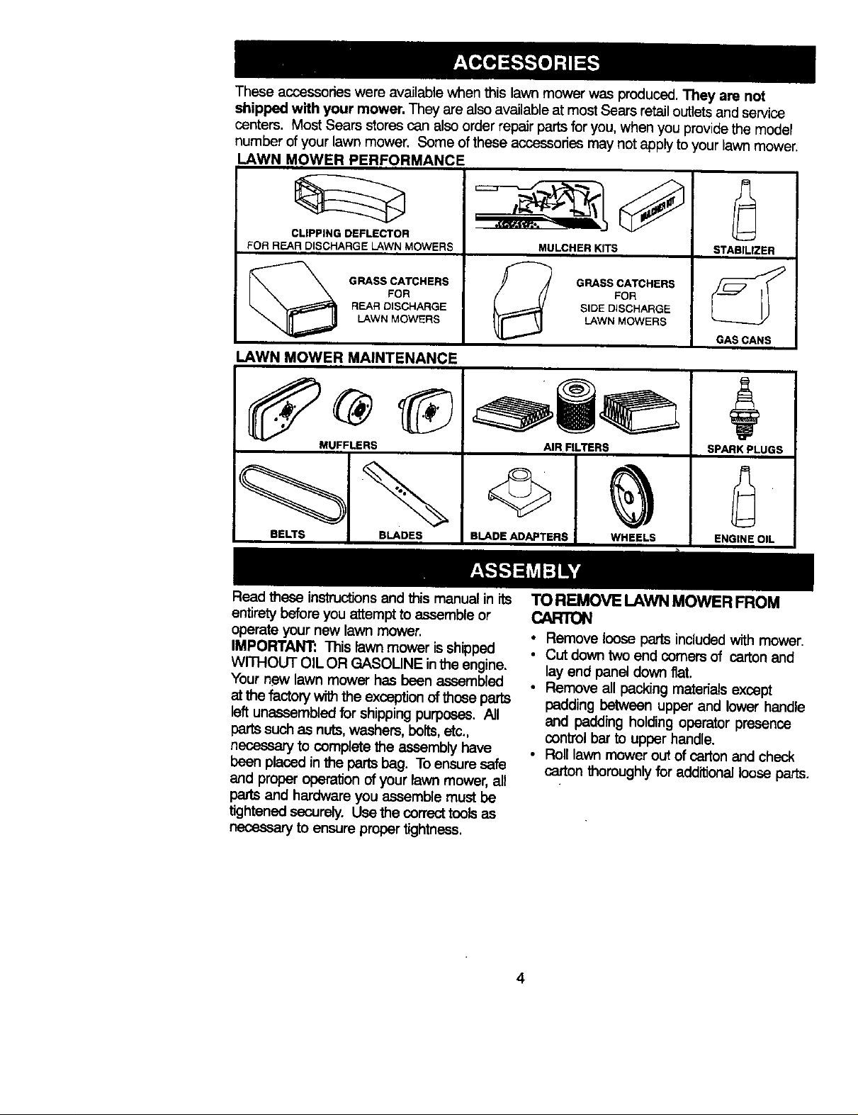
These accassodes were available when this lawn mower was produced. They are not
shipped with your mower. They ere alsoavailable at most Seers retailoutlets and service
centers. Most Sears stores can alsoorder repair partsfor you, when you providethe model
number of your lawn mower. Some ofthese accessories may not apply to your lawn mower.
LAWN MOWER PERFORMANCE
FOR REAR DISCHARGE LAWN MOWERS
CLIPPING DEFLECTOR
GRASS CATCHERS
REAR DISCHARGE
LAWN MOWERS
FOR
_1 GRASS CATCHERS
LAWN MOWER MAINTENANCE
MUFFLERS
BELTS BLADES
BLADE ADAPTERS WHEELS
Read these instructionslandthis manual in its
entirety before you attemptto assemble or
operate your new lawn mower.
IMPORTANT: This lawn mower isshipped
WITHOUT OIL OR GASOLINE inthe engine.
Your new lawn mower has been assembled
at the factonl withthe exception of those parts
leftunaasembled forshipping purposes. All
partssuch as nuts,washers, bolts,etc.,
necessary to complete the assembly have
been placed inthe parts beg. To ensure safe
and proper operation ofyour lawn mower, all
parts and hardware you assemble must be
tightened s_Jroly. Use the correct toolsas
necessary to ensure proper tightness.
MULCHER KITS
FOR
SIDE DISCHARGE
LAWN MOWERS
AIR F LTERS
STABILIZER
GAS CANS
SPARK PLUGS
ENGINE OIL
TOREMOVELAWNMOWERFROM
CARTON
• Remove loose parts included with mower.
• Cut down two end comers of cartonand
lay end panel down flat.
• Remove all packing materials except
padding between upper and lower handle
and padding holding operator presence
control bar to upper handle.
• Roll lawn mower out of carton and check
carton thoroughlyfor additionalloose parts.
4
Page 5
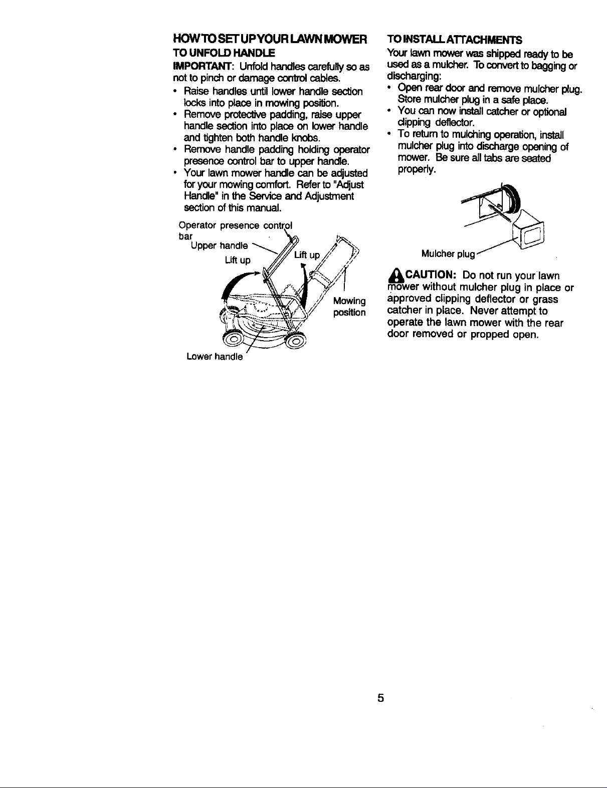
HOWTOSET'UPYOURLAWNMOWER
TOUNFOLDHANDLE
IMPORTANT:Unfoldhandlescarefullysoas
notto pinch or damage (_:)nVolcables.
• Raise handles until lower handle section
locks into place in mowing position.
• Remove protective padding, raise upper
handle section into place on lower handle
and tighten both handle knobs.
• Remove handle padding holding operator
presence controlbar to upper handle.
• Your lawnmower handlecan be adjusted
for your mowing comfort. Refer to "Adjust
Handle" in the Service and Adjustment
section of this manual.
Operator presence
bar
Mowing
position
TO INSTAU. ATI'ACHMENTS
Your lawn mower was shipped ready to be
used as a mulcher. To convert to bagging or
discharging:
• Open rear door and remove mulcher plug.
Store mulcher plug in a safe plaoe.
• You can now installcatcher oroptional
dipping deflector.
• To retum to mulching operation, install
mulchar p_j into discharge opening of
mower. Be sure all tabs are seated
proparly.
Mulcherplu
_CAUTION: Do not run your'lawn
mower without mulcher plug in place or
approved clipping deflector or grass
catcher in place. Never attempt to
operate the lawn mower with the rear
door removed or propped open.
Lower handle
5
Page 6
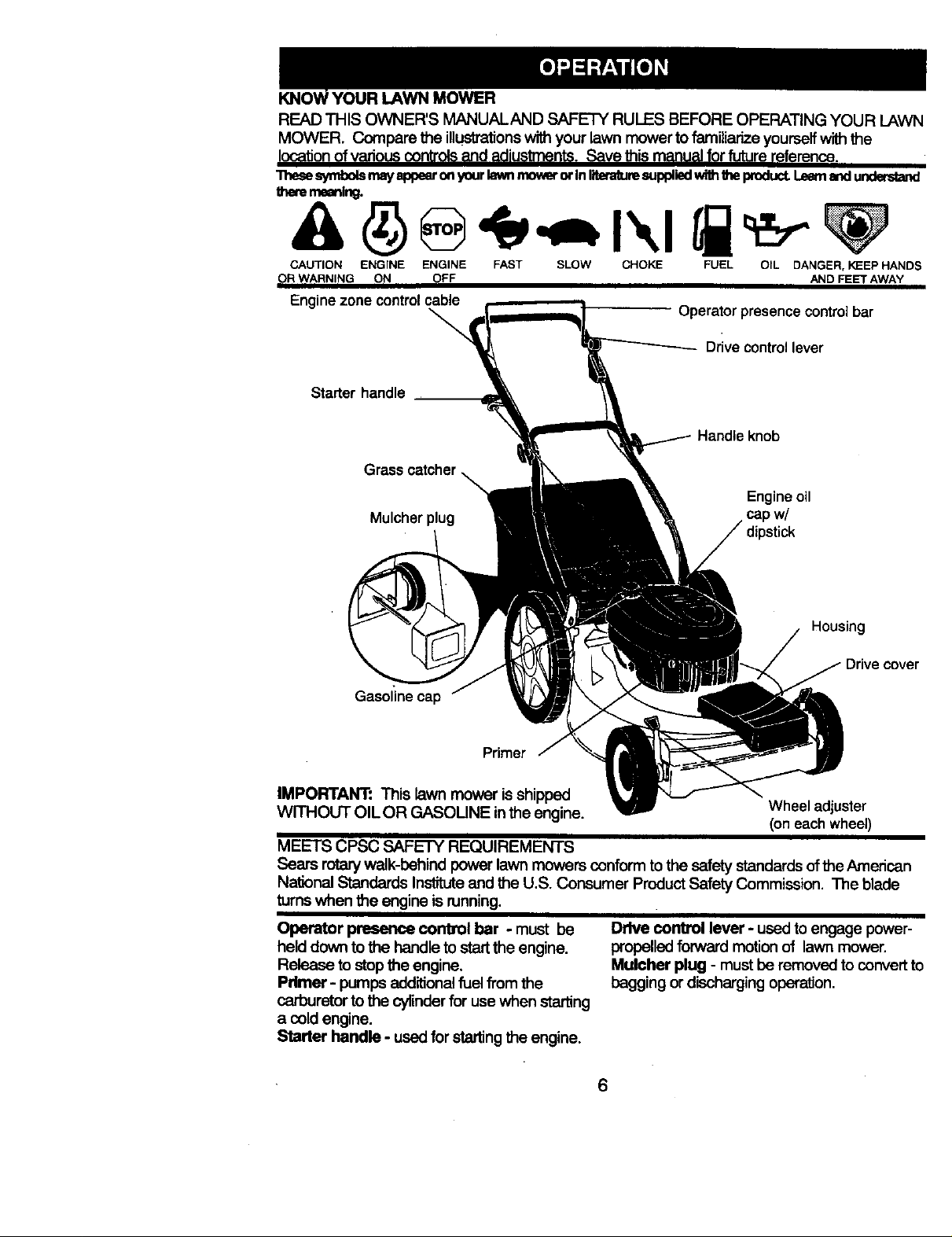
YOUR LAWN MOWER
READ THIS OWNER'S MANUALAND SAFETY RULES BEFORE OPERATING YOUR LAWN
MOWER. Compare the illustrations with your lawn mower to familiarize yourself with the
location of various controls and adiustments. Save this manual for future re_erence.
"ntesesymbols mayappearonyourla_mmover or In literaturesupplied withtheproduct._ _ u_
theremeaning.
CAUTION ENGINE ENGINE FAST SLOW CHOKE FUEL OIL DANGER, KEEP HANDS
OR WARNING ON OFF AND FEET AWAY
Engine zone control cable
Operatorpresencecontrolbar
Drive control lever
Starter handle
Handle knob
Grass
Engineoil
Mulcherplug capw/
Housing
cover
Gasoline cap
Primer
IMPORTANT: This lawn mower is shipped
WITHOUT OIL OR GASOLINE inthe engine. Wheel adjuster
(on each wheel)
MEETS CPSC SAFETY REQUIREMENTS
Sears rotarywalk-behind power lawn mowers conformto the safety standardsofthe American
National Standards Instituteand the U.S, Consumer Product Safety Commission. The blade
turnswhen the engine is running.
Operator presence corfa_l bar - must be
held down to the handle to start the engine.
Release to stop the engine.
Primer - pumps additionalfuel from the
Drive control lever - used to engage power-
propelledforward motion of lawn mower.
Mulcher plug - must be removed to convert to
bagging or dischargingoperation.
carburetorto the cylinderfor use when starting
a cold engine.
Starter handle - used for startingthe engine.
Page 7
The operation of any lawn
mower can result in foreign
objects thrown into the eyes,
which can result in severe eye damage.
Always wear safety glasses or eye shields
while operating your lawn mower or
performing any adjustments or repairs.
We recommend a wide vision safety mask
over spectacles or standard, safety
glasses.
HOWTO USEYOUR LAWN MOWER
ENGINE SPEED
The engine speed was set at the factory
for optimum performance. Speed is not
adjustable.
ENGINE ZONE CONTROL
I_C.AUTION: Federal regulations
require an engine control to be installed
on this lawn mower in order to minimize
the risk of blade contact injury. Do not
under any circumstances attempt to
defeat the function of the operator control.
The blade turns when the engine is
running.
• Your lawn mower is equipped withan
operator presence control bar which
requiresthe operator to be positioned
behind the lawn mower handle to start and
operate the lawn mower.
TO ADJUST CUTTING HEIGHT
• Raise wheels for low cut and lowerwheels
for highcut.
• Adjustcuttingheight tosuit your require-
ments. Medium positionis best for most
lawns.
• To change cuttingheight, squeeze adjuster
lever toward wheel Move wheel up or
down to suityour requirements. Be sure all
wheels are in the same setting.
NOTE: Adjuster is properly positioned
when plate tab inserts into hole in lever.
Also, 9-position adjusters (ifso equipped)
allow lever to be positioned between the
plate tabs.
PlateTab
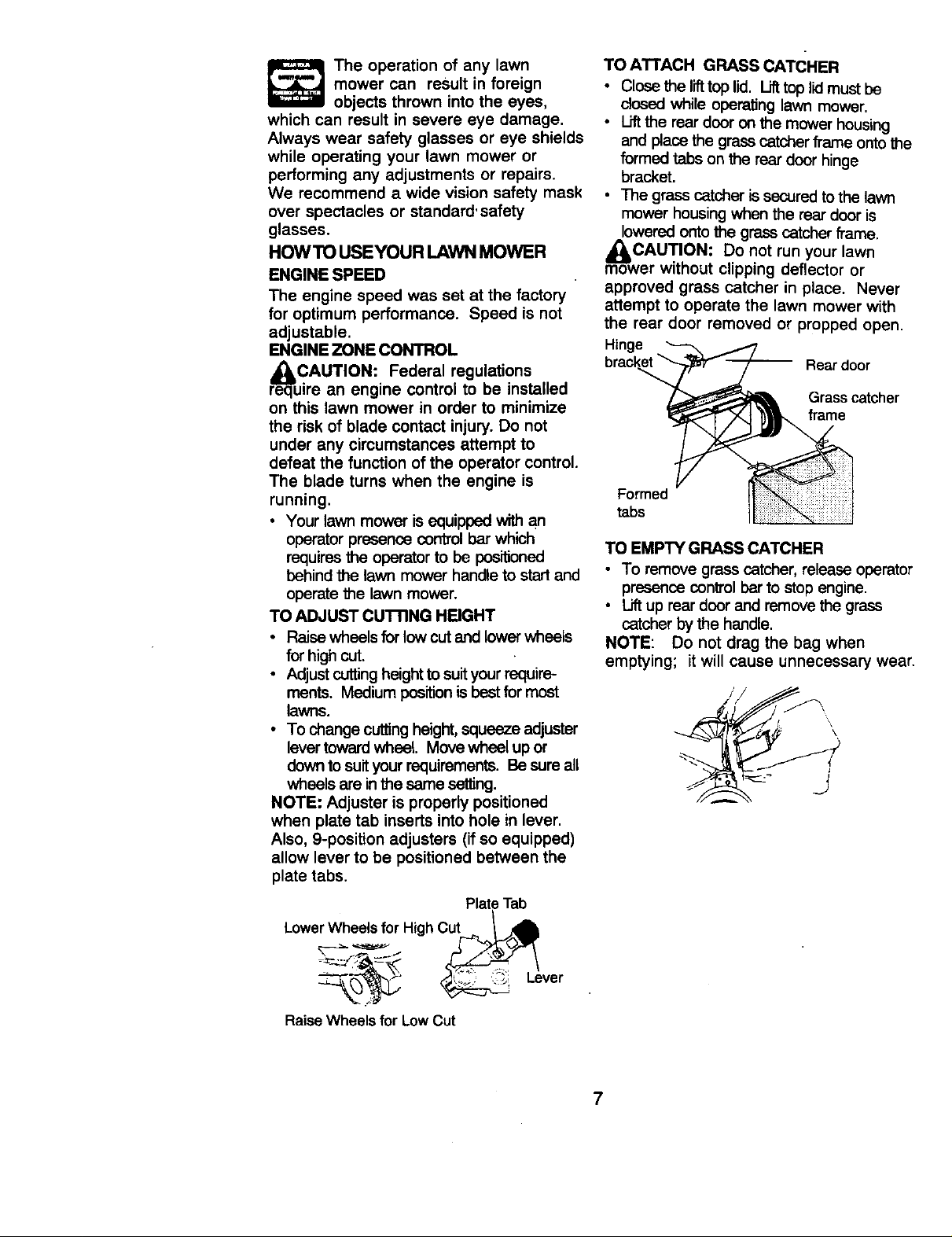
TO ATTACH GRASS cATCHER
• Close the I_ top lid. Lifttop lidmust be
dosed while operating lawn mower.
• Liftthe rear door on the mower housing
and place the grasscatcher frame ontothe
formed tabs on the rear door hinge
bracket.
• The grass catcheris secured tothe lawn
mower housingwhen the rear door is
lowered onto the grass catcher fl"ame.
m_owCAUTION: Do not run your lawn
er without clipping deflector or
approved grass catcher in place. Never
attempt to operate the lawn mower with
the rear door removed or propped open.
Hinge
Rear door
Grasscatcher
frame
Forme_
tabs
TO EMPTY GRASS CATCHER
• To remove grass catcher, release operator
presence controlbar to stop engine.
• Liftup rear door and remove the grass
catcher by the handle.
NOTE: Do not drag the bag when
emptying; it will cause unnecessary wear.
\
\
LowerWheels for High Cut _,.,_,,_,
ever- "_: ;:_':
Raise Wheels for Low Cut
Page 8
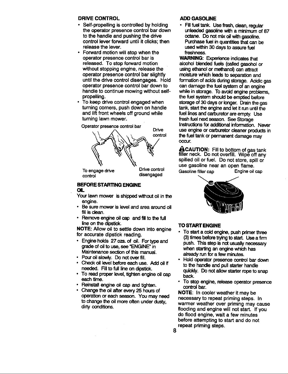
DRIVE CONTROL
• Self-prepelling is controlled by holding
the operator presence control bar down
to the handle and pushing the drive
control lever forward until it clicks; then
release the lever.
• Forward motion will stop when the
operator presence control bar is
released. To stop forward motion
without stopping engine, release the
operator presence control bar slightly
until the drive control disengages. Hold
operator presence control bar down to
handle to continue mowing without self-
propelling.
• To keep drive control engaged when
turning corners, push down on handle
and lift front wheels off ground while
turning lawn mower.
Operatorpresencecontrolbar
Drive
control
To engage drive Drive control
control disengaged
ADO GASOUNE
• Fillfuel tank. Use fresh, dean, regular
unleaded gasolinewith a minimum of 87
octane. Do notmix oil with gasoline.
Purchase fuel in quantities that can be
used within30 days to assure fuel
freshness.
WARNING: Experience indicatesthat
elcohol blended fuels (called gasohol or
using ethanol or me_an_ can attract
moisture which leads to separation and
formation of acids duringstorage. Acidicgas
can damage the fuel system of an engine
while in storage. To avoid engine problems,
the fuel system should be embed before
storage of 30 days or longer. Drain the gas
tank, start the engine and let itrun untilthe
fuel lines and carburetorare empty. Use
fresh fuel next season. See Storage
Inskuc_onsfor add_ information. Never
use engine or carburetor cleaner productsin
the fuel tank or permanent damage may
occur.
_CAUTION: Fill to bottom of gas tank
filler neck. Do not overfill. Wipe off any
spilled oil or fuel. Do not store, spill or
use gasoline near an open flame.
Gasolinefillercap Engineoilcap
BEFORE STARTING ENGINE
OIL
Your lawn mower is shipped without oil inthe
engine.
• Be sure mower is level and area around oil
fillis clean.
• Remove engine oil cap and fillto the full
lineon the dipstick.
NOTE: Allow oil to settle down into engine
for accurate dipstick reading.
• Engine holds 27 ozs. of oil. Fortype and
grade of oil to use, see "ENGINE" in
Maintenance section of this manual.
• Pour oil slowly. Do notover fill
• Check oil level before each use. Addoilif
needed. Fillto full line on dipstick.
• To read proper level, tighten engine oilcap
each lime.
• Reinstall engine oil cap and _htan.
• Change the oilafter every 25 hours of
operation or each season. You may need
to change the oil more often underdusty,
dirty conditiorls.
TO START ENGINE
• TO start a cold engine, push pdmer three
(3) times beforetryingto start. Use a firm
push. This step isnot usuallynecessary
when starling an engine which has
aJreadyrun for a few minutes.
• Hold operator presence controlbar down
to the handle and pull starter handle
quickly. Do notallow starter ropeto snap
beck.
• To stop engine, release operator presence
contral bar.
NOTE: In cooler weather it may be
necessary to repeat priming steps. In
warmer weather over priming may cause
flooding and engine will not start. If you
do flood engine, wait a few minutes
before attempting to start and do not
repeat priming steps.
8
Page 9
MOWING TIPS
• Under certain conditions, such as very
tall grass, it may be necessary to raise
the height of cut to reduce pushing effort
and to keep from overloading the engine
and leaving clumps of grass clippings. It
may also be necessary to reduce
ground speed and/or run the lawn
mower over the area a second time.
• For extremely heavy cutting, reduce the
width of cut by overlapping previously
cut path and mow slowly.
• For better grass bagging and most
cutting conditions, the engine speed
should be set in the fast position.
• When using a rear discharge lawn
mower in moist, heavy grass, clumps of
cut grass may not enter the grass
catcher. Reduce ground speed (push-
ing speed) and/or run the lawn mower
over the area a second time.
• If a trail of clippings is left on the right
side of a rear discharge mower, mow in
a clockwise direction with a small
overlap to collect the clippings on the
next pass.
• Pores in cloth grass catchers can
become filled with dirt and dust with use
and catchers will collect less grass. To
prevent this, regularly hose catcher off
with water and let dry before using.
• Keep top of engine around starter clear
and clean of grass clippings and chaff.
This will help engine air flow and extend
engine life.
MULCHING MOWING TIPS
IMPORTANT: For best performance, keep
mower housingfree of built-upgrass and
trash. See "Cleaning" in Maintenance section
ofthis manual.
• The special mulching blade will recutthe
grass clippingsmany times and reduce
them insize so that as they fall ontothe
lawn they will disperse intothe grass and
not be noticed. Also, the mulched grass will
biodegrade quicklyto provide nutrientsfor
the lawn. Always mulch with yourhighest
engine (blade) speed as thiswill providethe
best recuttingactionof the blades.
• Avoid cuttingyour lawn when itis wet. Wet
grass tends toform dumps and interferes
withthe mulchingaction. The besttime to
mow your lawn is the early afternoon. At
this time the grass has dried and the newly
cutarea willnot be exposed to the direct
sun.
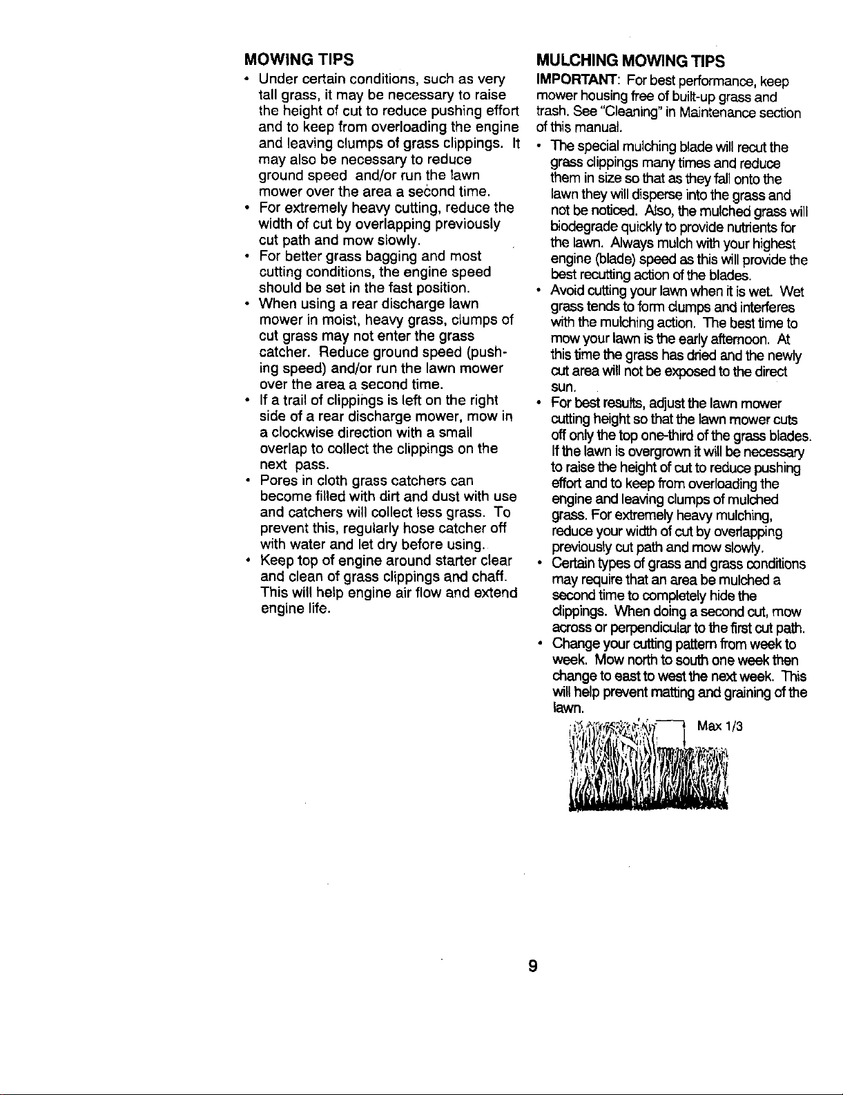
• For best results,adjust the lawn mower
cuttingheight so that the lawn mower cuts
offonlythe top one-third ofthe grass blades.
Ifthe lawn is overgrown itwillbe necessary
to raise the height of cut to reduce pushing
effort and to keep from overloadingthe
engine and leaving clumpsof mulched
grass. For extremely heavy mulching,
reduce yourwidth of cut by overlapping
previously cut path and mow slowly.
• Certain types of grass and grass conditions
may require that an area be mulched a
second time to completely hide the
clippings. When doing a second cut,mow
across or perpendicular to the first cut path.
• Change your cutting pattem from week to
week. Mow north to south one week then
change to eastto west the next week. This
will help prevent matting and graining of the
lawn.
Max 1/3
9
Page 10
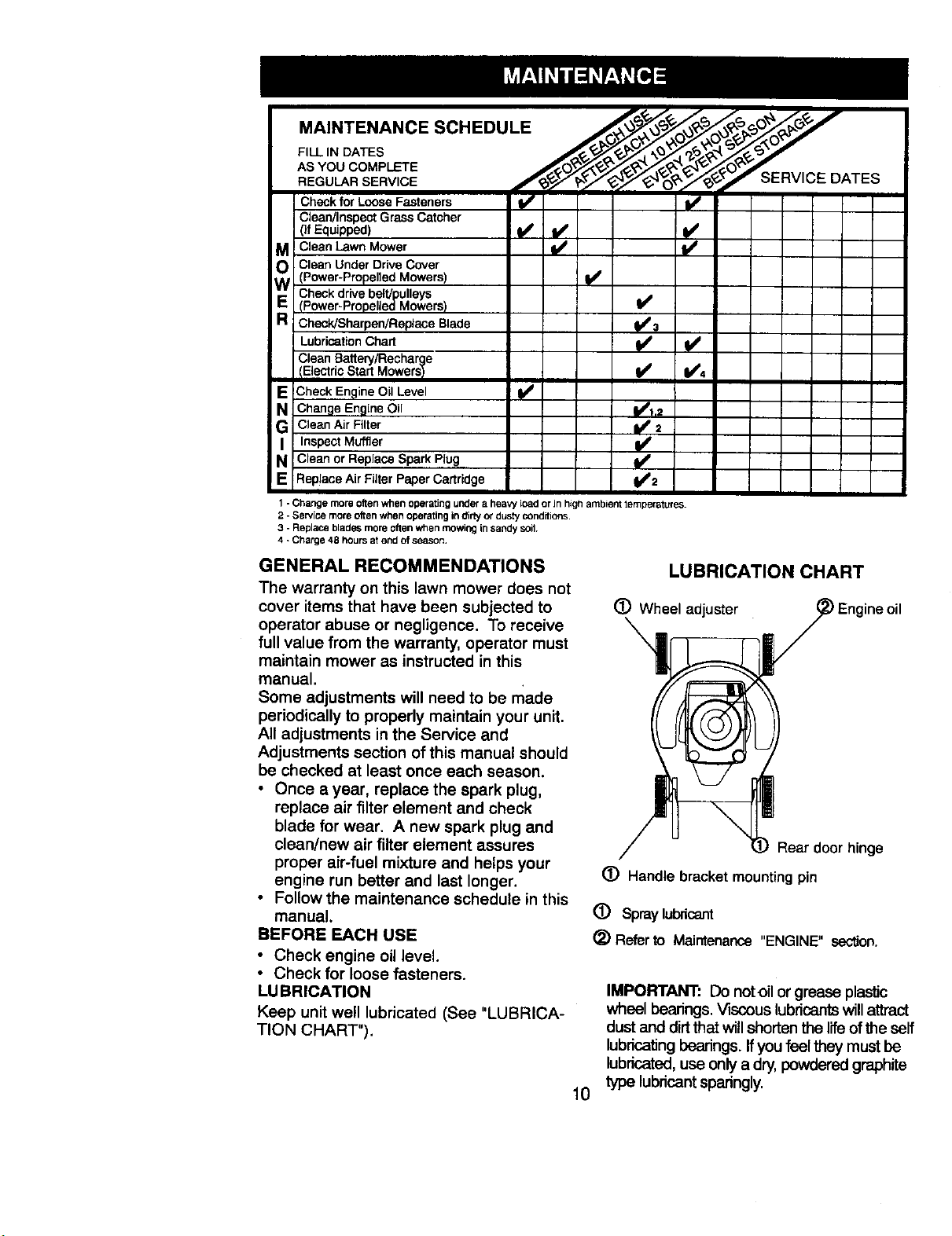
AS YOU COMPLETE __t_,_/t_,_ tK_'_r"-_"
REGULAR SERVICE f_._'_,_Z_'4y_'4_"O__._ _ERVICE DATES
Check for Loose Fasteners _ I_
Clean/Inspect Grass Catcher
M Clean Lawn Mower
O Clean Under Drive Cover(Power-Propelled Mowers) I_
Checkdrive belt/pulleys
Check!Sharpen/Replace Blade 3
RE (Power-Propelled Mowers)
Lubrication Chart
Clean Battery/Recharge
IElectricStart MowersI I_ I/'4
V W W
E Check Engine Oil Level
N Change Engine Oil 1111.2
G Clean Air Filter _ 2
I Inspect Muffler I_
a Clean or Replace Spark Plug
¥,
E ReplaceAirFilterPaperCartridge Ij#'2
1 -Change more often when operating uPPera heavy lOad or Jnhigh ambient temperatures.
2 -Service more often when operatingin ditty or dusty conditions.
3 - Replace blades more oftenwhen mowing insandy soil
4 -Charge 48 hours at end of season,
GENERAL RECOMMENDATIONS
LUBRICATION CHART
The warranty on this lawn mower does not
cover items that have been subjected to
(_) Wheel adjuster Engine oil
operator abuse or negligence. To receive
full value from the warranty, operator must
maintain mower as instructed in this
manual.
Some adjustments will need to be made
periodically to properly maintain your unit.
All adjustments in the Service and
Adjustments section of this manual should
be checked at least once each season.
• Once a year, replace the spark plug,
replace air filter element and check
blade for wear. A new spark plug and
clean/new air filter element assures
Rear door hinge
proper air-fuel mixture and helps your
engine run better and last longer.
(_) Handle bracket mounting pin
• Follow the maintenance schedule in this
manual.
BEFORE EACH USE
(_) Spraylubricant
(_) Refer to Maintenance "ENGINE" section.
• Check engine oil level.
• Check for loose fasteners.
LU BRICATION
Keep unit well lubricated (See "LUBRICA-
TION CHART").
IMPORTANT: Do notoil or grease plastic
wheel bearings.Viscous lubricants willattract
dust and dirtthat will shorten the life of the self
lubricating bearings. If you feel they must be
lubricated, use only a dry, powdered graphite
type lubricant sparingly.
10
Page 11

PRODUCT SPECIFICATIONS
MODEL NUMBER
_ERIALNUMBER
)ATE OF PURCHASE
HORSEPOWER:
GASOLINE CAPACITY/TYPE:
31LTYPE (API-SF/SG/SH)':
OIL CAPACITY:
SPARK PLUG/GAP: .030")
VALVE CLEARANCE:
SOLID STATE IGNITION
AIR GAP: .0125 IN.
3LADE BOLT TORQUE: 35-40 FT. LBS.
The model and serial numbers will be found on a decal attached to the rear of the
lawn mower h0using.Record both serial number and date of purchase inspace
provided above.
LAWN MOWT=R
Always observe safety rules when performing
any maintenance.
TIRES
• Keep tires free of gasoline,oil, or insect
controlchemicals which can harm rubber.
• Avoid stumps, stones, deep ruts, sharp
objects and other hazards that may cause
tire damage.
BLADE CARE
For best results, mower blade must be
kept sharp. Replace bent or damaged
blades.
TO REMOVE BLADE
• Disconnect spark plug wire from spark
plug and place wire where it cannot
come in contact with spark plug.
• Turn lawn mower on its side. Make
sure air filter and carburetor are up.
• Use a wood block between blade and
mower housing to prevent blade from
turning when removing blade bolt.
• Protect your hands with gloves and/or
wrap blade with heavy cloth.
• Remove blade bolt by turning counter-
clockwise.
• Remove blade and attaching hardware
(bolt, lock washer and hardened
washer).
NOTE: Remove the blade adapter and
check the key inside hub of blade adapter.
The key must be in good condition to work
properly. Replace adapter if damaged.
TO REPLACE BLADE
• Position the blade adapter on the
• Position blade on the blade adapter
• Be sure the trailing edge of blade
• Install the blade bolt with the lock
• Use block of wood between blade and
• The recommended tightening torque is
917.377990
6.75
1.5 QUARTS
UNLEADED REGULAR
SAE 30 (ABOVE 32°F)
SAE 5W-30 (BELOW 32°F)
27 OZS.
CHAMPION RJ19LM OR J19LM
INTAKE: .004 - .008
EXHAUST: .004 - .008
engine crankshaft. Be sure key in
adapter and crankshaft keyway are
aligned.
aligning the two (2) holes in the blade
with the raised lugs on the adapter.
(opposite sharp edge) is up toward the
engine.
washer and hardened washer into
blade adapter and crankshaft.
lawn mower housing and tighten the
blade bolt, turning clockwise.
35-40 ft. Ibs.
11
Page 12

IMPORTANT: Blade bott is grade 8 heat
treated.
TO SHARPEN BLADE
NOTE: We do not recommend sharpen-
ing blade - but if you do, be sure the blade
is balanced.
Care should be taken to keep the blade
balanced. An unbalanced blade will
cause eventual damage to lawn mower or
engine.
• The blade can be sharpened with a file
or on a gdnding wheel Do not attempt
to sharpen while on the mower.
• To check blade balance, drive a nail
into a beam or wall. Leave about one
inch of the straight nail exposed. Place
center hole of blade over the head of
the nail. If blade is balanced, it should
remain in a horizontal position. If either
end of the blade moves downward,
sharpen the heavy end until the blade
is balanced. Crank shaft
Blade keyway
Key
Blade
Crank
bolt shaft
Lock Blade
washer Hardened edge adapter
washer
GRASS CATCHER
• The grass catchermay be hosed with
water, but must be dry when used.
• Check your grass catcheroften for
damage or deterioration. Through normal
use itwillwear. ffcatcher needs replacing,
replace only with a manufacturer approved
replacement catcher. Give the lawn
mower model number when ordering.
DRIVE WHEELS
Check front drive wheels each time before
you mow to be sure they move freely.
The wheels not turning freely means
trash, grass cuttings, etc. are in the drive
wheel area and must be cleaned to free
drive wheels.
If necessary to clean the drive wheels,
check both front wheels.
• Remove hubcaps, hairpin cotters and
washers.
• Remove wheels from wheel adjusters.
• Remove any trash or grass cuttings
_om inside the dust cover, pinion and/
or drive wheel gear teeth.
• Put wheels back in place.
• If after cleaning, the drive wheels do
not turn freely, contact your nearest
authorized service center.
GEAR CASE
• To keep your drive system working
properly, the gear case and area
around the drive should be kept clean
and free of trash build-up. Clean under
the drive cover twice a season.
• The gear case is filled with lubricant to
the proper level at the factory. The only
time the lubricant needs attention is if
service has been performed on the
gear case.
• If lubricant is required, use only Texaco
Starplex Premium 1 Grease, Part No.
750369. Do not substitute.
ENGINE
LUBRICATION
Use only high quality detergent oil rated
with API service classification SF, SG or
SH. Select the oil's SAE viscosity grade
according to your expected operating
temperature.
SAEVISCOSITY GRADES
0"
.=o'
TEMPERATURE RANGE ANTICIPATED BEFORE NEXT OIL CHANGE
NOTE: Although multi-viscosity oils
(5W30, 10W30 etc.) improve starting in
cold weather, these multi-viscosity oils
will result in increased oil consumption
when used above 32°F. Check your
engine oil level more frequently to avoid
possible engine damage from running
low on oil.
Change the oil after every 25 hours of
operation or at least once a year if the
lawn mower is not used for 25 hours in
one year.
Check the crankcase oil level before
starting the engine and after each five (5)
hours of continuous use. Tighten oil plug
securely each time you check the oil
level.
12
Page 13

TO CHANGE ENGINE OIL
NOTE: Before tipping lawn mower to
drain oil, drain fuel tank by running
engine until fuel tank is empty.
• Disconnect spark plug wire from spark plug
and place wire where it cannot come in
contact with spark plug.
• Remove engine oilcap; lay aside on a
dean surface.
• "13plawn mower on its side as shown and
drain oil into a suitable container. Rock
lawn mower back and forthto remove any
oiltrapped inside of engine.
• Wipe offany spilled oil on lawn mower and
on side of engine.
• Fillengine with oil. Fillonlyto the "FULL"
line on the dipstick. DO NOT overfill.
• Replace engine oil cap.
• Reconnect spark plugwire to spark plug.
AIR FILTER
Your engine will not run properly and may
be damaged by using a dirty air filter.
Replace the air filter every year, more
often if you mow in very dusty, dirty
conditions. Do not wash air filter.
TO CHANGE AIR FILTER
• Loosen cover knob.
• Swing cover down and remove from
hinge.
• Pull paper filter out of air cleaner body.
• Clean air cleaner cover and body.
• Install a new paper filter.
• Reinstall cover to air cleaner body. Be
sure hinge is assembled properly.
• Swing cover up and tighten cover knob.
(Do not overtighten).
MUFFLER
Inspect and replace corroded muffler as it
could create a fire hazard and/or damage.
SPARK PLUG
Change your spark plugeach year to make
your engine start easier and runbatter. Set
spark plug gap at .030 inch.
CLEANING
IMPORTANT: For best performance, keep
mower housing free of built-up grass and
trash. Clean the underside of your mower
after each use.
wI_reCAUTION: Disconnect spark plug
from spark plug and place wire
where it cannot come in contact with the
spark plug.
• Turn lawn mower on itsside. Make sure air
filterand carburetorare up, Clean the
underside of your lawn mower by scraping
to remove build-up of grass and trash.
• Clean engine often to keep bash from
accumulating. A dogged engine runs
hotter and shortens engine life.
• Keep finished surfaces and wheels free of
ell gasoline, oil,stc.
• We do not recommend usinga garden
hose to clean lawn mower unless the
electricalsystem, muffler,air filter and
carburetor are covered to keep water out.
Water in engine can resultin shortened
engine life.
CLEAN UNDER DRIVE COVER
Clean underdrive cover st least twice a
season. Scrape underside of cover with putty
Imife or similar tool to remove any build-upof
trash or grasson underside ofdrive cover.
Paper filtei"
Air r cover
Cover knob
13
Page 14

_IILCAUTION: Before performing
service and adjustments:
Release control bar and stop engine.
Make sure the blade and alLmoving
parts have completely stopped.
Disconnect spark plug wire from spark
plug and place where it cannot come
in contact with plug.
LAWN MOWER
TO ADJUST cu'n'ING HEIGHT
See 'qO ADJUST CLrl-rlNG HEIGHT" inthe
OperalJonsection of this manual.
REAR DEFLECTOR
The rear deflector,attached between the rear
wheals of your lawn mower, is provided to
minimize the possibilitythat objects will be
thrown out the rear ofthe lawn mower into the
operators mowing position. Ifthe rear
deflector becomes damaged, it should be
replaced.
TO REMOVE/REPLACE DRIVE BELT
• Remove drive cover. Remove belt by
pushing down on gear case pulley and roll
beit off,
• Turn lawn mower on its sidewith carbure-
tor and fuel cap up,
• Remove blade.
• Remove debris shield.
• Remove belt from engine pulley on
crankshaft.
• Install new belt by reversing above steps.
• /Mways use factory approved belt to assure
fit and long life. I ,i
Drive _i' ik \
cover _ i /
any
TOADJUSTHANDLE
The handle can be mounted in a high or
low position. The mounting holes in the
bottom of lower handle are off center for
raising or lowering the handle.
• Remove upper handle and all parts
attached to lower handle.
• Remove hairpin cotters from lower
handle bracket mounting pin.
• Squeeze lower handle in to remove it
from mounting pins.
• Turn lower handle over to raise or lower
handle.
• Squeeze lower handle in and position
holes onto mounting pins on handle
bracket.
• Reassemble upper handle and all parts
removed from lower handle.
Mowing Mowing
position ,'-_,' position
Low position High position
oo" lti l
,,sh N' II
downJ L - lll
\
Lower
Rotate
14
Page 15

ENGINE SPEED
Your engine speed has been factory set.
Do not attempt to increase engine speed
or it may result in personal injury. If you
believe that the engine is running too fast
or too slow, take your lawn mower to an
authorized service center for repair and
adjustment.
CARBURETOR
Your carburetor has a non-adjustable
fixed main jet for mixture control. If your
engine does not operate properly due to
suspected carburetor problems, take your
lawn mower to an authorized service
center for repair and/or adjustment.
IMPORTANT: never tamper with the
engine governor, which is factory set for
proper engine speed. Overspeeding the
engine above the factory high speed
setting can be dangerous, if you think the
engine-governed high speed needs
adjusting, contact your nearest authorzed
service center, which has proper
equipment and experience to make any
necessary adjustments.
TO ASSEMBLE GRASS CATCHER
• Insert leg of tubular frame through front
opening of grass catcher and thread
frame into sewn hem of bag.
NOTE: Keep bag hem gathered on the
straight leg of the tubular frame.
• When frame comes out the other end of
sewn hem, immediately work the end of
frame down inside the bag as shown in
inset.
• Slide sewn hem evenly around the
tubular frame until both ends of frame
are exposed out of the front opening.
• Assemble lower frame to tubular frame
as shown. Be sure handle is outside of
bag and frames are fully seated as
shown in inset.
• Slip vinyl bindings over frame.
NOTE: If vinyl bindings are too stiff, hold
them in warm water for a few minutes. If
bag gets wet, let it dry before using.
• Close the flip lid. Flip lid must be closed
while operating lawn mower.
CAUTION: Do not run your lawn
er without clipping deflector or
approved grass catcher in place. Never
attempt to operate the lawn mower with
the rear door removed or propped open.
Sewn
Tubularframe hem
Sewn hem Flip lid
Lower frame
(Frames
must be
fully
seated)
Tubular frame
Lower frame handle
/
/
15
Page 16

immediately prepare your lawn mower for
storage atthe end of the season or ifthe unit
will not be used for 30 days or more,
LAWNMOWER
When lawn mower isto be stored for a period
of time, clean itthoroughly, remove all dirt,
grease, leaves, etc. Store ina clean, dry area.
• Clean entire lawn mower (See "CLEAN-
ING" in the Maintenance section of this
manual).
• Lubricate as shown in the Maintenance
section of this manuai.
• Be sure that all nuts, bolts, screws, and pins
are securely fastened. Inspect moving
parts for damage, breakage and wear.
Replace if necessary.
• Touch up all rusted or chipped paint
surfaces; sand lightly before painting.
HANDLE
You can fold your lawn mower handle for
storage.
• Squeeze the bottom ends of the lower
handle toward each other until the lower
handle clears the handle bracket, then
move handle forward.
• Loosen upper handle mounting bolts
enough to allow upper handle to be folded
back.
IMPORTANT: When folding the handle for
storage or tl'ansportation, be sure tofold the
handle as shown or you any damage the
control cables.
• When setting up your handle from the
storage posi'don, the lower handle will
automatically lock into the mowing position.
Lower
handle
Squeeze tofold
Handle
bracket
Operator presence control bar
\ _ handle
Upper
Fold foward ,_/;:'"'.
for storage •J
:" _' / Fod
':: :':' ":' _ backward
Lower Mowing
handle position
ENGINE
FUELSYSTEM
IMPORTANT: It is important to prevent gum
deposits from forming in essentialfuel system
parts such as carburetor,f fuel filter, fuel hose
or tank duringstorage. Also, experience
indicates that alcohol blended fuels ( sailed
gasohol or using ethanol or methanol) can
attract moisture which leads to separation and
forrnatlonof acids during storage. Acidic gas
can damage the fuel system of an engine
while instorage.
• Drain the fuel tank.
• Start the engine and let it run until the fuel
lines and carburetor are empty.
• Never use engine or carburetor cleaner
products in the fuel tank or permanent
damage may occur,
• Use fresh fuel next season.
NOTE: Fuel stabilizeris an acceptable
aitemative in minimizing the formation of fuel
gum deposits during storage. Add stabilizer
to gasoline in fuel tank or storage container.
Always follow the mix ratio found on stabilizer
container. Run engine at least 10 minutes
after adding stabilizer to allow the stabilizer to
reach the carburetor. Do not drain the.gas
tank and carburetor if using fuel stabilizer.
Hairpin
cotter
16
Page 17

ENGINEOIL
Drain oil (with engine warm) and replace with
clean engine oil. (See "ENGINE" inthe
Maintenance section of this manual).
CYUNDER
• Remove spark plug.
• Pour one ounce (29 ml) of oilthrough spark
plug hole into cylinder.
• Pullstarter handle slowtya few times to
distribute oil.
• Replace with new spark plug.
OTHER
• Do not store gasoline from one season to
another.
TROUBLESHOOTING CHART
PROBLEM
CAUSE CORRECTION
• Replace your gasoline can if your can
startsto rust. Rust and/or dirt inyour
gasoline will cause problems.
• If possible, storeyour unit indoorsand
cover itto give protectionfrom dust and dirt.
• Cover your unitwith a suitable protective
cover that does not retain moisture. Do
not use plestJc.Plasticcannot bres_e
which allows condensationto form and will
cause your unitto rust.
IMPORTANT: Never cover mower while
engine and exhaust areas are stillwarm.
_CAUTION: Never store the lawn
_-Swer with gasoline in the tank inside a
building where fumes may reach an open
flame or spark. Allow the engine to cool
before storing in any enclosure.
Does notstad
Lossofpower
.1. Dirtyair filter.
2. Out of fuel
3. Stale fuel.
4. Water in fuel.
5. Spark plugwire is
disconnected.
6. Bad spark plug.
7. Loose blade or broken blade
adapter.
8. Control bar in released
posH_on.
9. Con_'olbardefec_ve.
1. Rear of lawn mower housi_
or cuffing blade dragging
in heavy grass.
2. Cutting too much grass.
3. Dirty air filter.
4. Buildupof grass, leaves,
and trash under mower.
5. Too much oil in engine.
6. Walking speed too fast.
Clean/replace air filter.
2. Fillfuel tank.
3. Draintank and refillwith
fresh clean fuel.
4. Drainfuel tank and
carburetor and refilltank
with fresh gasoline.
5. Connect wire to plug.
6. Replace spark plug.
7. Tighten blade bolt or
replace blade adapter.
8. Depress control bar to
handle.
9. Replace controlbar.
1. Set to "Higher Cut"
position.
2. Setto "Higher Cut"
position.
3. Cle_u't/replaceair filter.
4. Clean underside of mower
housing.
5. Check oillevel.
6. Cut at slower waildng
speed.
Poor cut - uneven 1. Wom, bent or loose blade.
2. Wheel heights uneven.
3. Buildupof grass, leaves
and trash urger rnower.
17
1. Replace blade. _ghten
blade bo_.
2. Set all wheais at same
height
3. Clean underside of
mower housing.
Page 18

TROUBLESHOOTINGCHART
PROBLEM CAUSE CORRECTION
Excessive
vibration
Starterropehard
topull
Loss of drive
Grass catcher
not _llng (Ifss
equipped)
1. Worn, bent or loose blade.
2. Bent engine crankshaft.
1. Engine flywheel brake is on
when control bar is released.
2. Bent engine crankshaft.
3. Blade adapter broken.
4. Blade dragging in grass.
1. Drive wheels not turning
with drive control engaged.
2. Belt not driving
1. Cutting height too low.
2. Uft on blade worn off.
3. Catcher not venting air.
1. Replace blade. lighten
blade bolt.
2. Contact an authonzed
service center.
1. Depress control bar to
upper handle before
pulling starter rope.
2. Contact an authorized
service center.
3. Replace blade adapter.
4. Move lawn mower to cut
grass or to hard surface.
1. Adjust or replace drive control
cable.
2. Put belt on pulleys or
replace belts if broken.
1, Raise cutting height.
2, Replace blade,
3. Clean grass catcher.
Hard to push
1. Grass istoo highor wheel
height is too low.
2. Rear of lawn mower
housing or blade dragging
in grass.
3. Grass catcher too full.
4. Handle height position not
right for you.
1. Raise cutting height.
2. Raise rear of lawn mower
housing one (1) setting
higher.
3. Empty grass catcher.
4. Adjust handle height to
suit.
18
Page 19

36
Page 20

ROTARY LAWN MOWER - - MODEL NO. 917.377990
GEAR CASE ASSEMBLY PART NUMBER 702511
17
15
14
KEY
NO.
2
3
4
6
17490416
57072
48373
PART
NO.
137055X004
137053
77881
137051
KEY PART
DESCRIPTION NO. NO.
Tapping Screw 1/4o20 x 9 137074 Drive Shaft
1-1/4 10 57079 Hardened Washer
Engagement Bracket 11 131484 Clutch Yoke
Shifter 12 7(30343 Bushing
Seal 13 86447 Plug
Gear Case Halves _t 14 137050 Helical Gear
(Includes Key Nos. 4, 15 750436X Clutch Jaw
and 7) 16 750369 Grease
Bearing 17 12000003 E-Ring
Worm Shaft 18 850848 Hi-Pro Key
19 81585X004 Spring Bracket
DESCRIP_ON
NOTE: All component dimensions given
in U.S. inches. 1 inch = 25.4 mm
37
Page 21

ROTARYLAWNMOWERMODELNUMBER917.377990
1
8
31
I
22
35
28
29
30
10,
10
14
69
27
/
/-
F
16 12
, 4
35 53
20
37
56
52
44
51
34
32
30
29
28
41
69
Page 22

ROTARY LAWN MOWER MODEL NUMBER 917.377990
@
KEY PART
NO. NO. DESCRIPTION
1 165452X479
2 158152
4 150425
5 66426
6 136376
8 145793
9 151023
10 128415
11 150050
12 STD5125(_
13 63601
14 186374)(479
15 700365)(479
16 133190X479
17 140661)(479
20 140540
22 85543
23 87677
25 83923
27 151138
28 142748
" 29 61651
30 750913X004
31 701037
32 700331X004
34 146630
35 750085X007
37 150078
38 88348
39 161814X479
40 161812X479
UpperHandle
EngineZoneControlCable
MulcherPlug
Wire'Re
HandleKnob
ControlBar
RearDoorKit
PopRivet
SerfTappingScrew #10-24 x 5/8
RexTappingScrew w/Sems 1/4-20 x 1/2
Nut 1/4 - 20
BackPlate
Side Baffle
DischargeBaffle
Rear Baffle
Reer Skirt
EnginePulley
Hi-ProKey #505
HexFlange Nut
Wheel
ShoulderBolt 3/8-16 x 1
SpdngWasher
Axle ArmAssembly
SelectorKnob
SelectorSpdng
Spacer
WheelAdjustingBracket
ThreadCuttingScrew w/Sems 5/16-18 x 3/4
Flatwasher3/6
HandleBracketAssembly(Left)
HandleBracket Assembly(Right)
KEY PART
NO. NO. DESCRIPTION
41 150406
44 161769
46 851514
47 157101
48 851074
49 85O263
50 851084
51 165548
52 85463
53 74760612
55 751592
56 88652
57 51793
58 157081)(479
59 131959
61 132001
62 134612
64 ......
69 151440
- - 161058
- - 169972
Available accessories not included with lawn mower:
- - 71 33303 Clipping Deflector
- - 71 33623 Gas Can (2.5 gal.)
- _ 71 33500 Fuel Stabilizer
- 71 33027 SAE 30W Oil (27 oz.)
- - 71 33417 Dust Shield
- - 71 33316 MowerCover
Hex Head Thread Rolling Screw 3/8-16 x 1-1/8
Lawn Mower Housing (Incl. Key #14, 15, 51)
Blade Adapter
Blade22"
I_ardened Washer
Helical Washer 3/8-24 x 1-3/8 Gr. 8
Hex Head Machine Screw 3/8-24 x 1-3/8 Gr. 8
Front Baffle Kit
Danger Decal
Hex Bolt 3/8-16x3/4
Locknut 3/8-16
Hinge Screw 1/4-20 x 1-1/4
Hairpin Cotter
Lower Handle
Handle Bolt
RopeGuide
Debris Shield
Engine - (See Breakdown)
Tecumseh Model 143.996704
Hubcaps
Warning Decal (Not Shown)
Owner's Manual (English/Spanish)
Page 23

ROTARY LAWN MOWER MODEL NUMBER 917.377990
18
14
16
15
14
11
/
13
I
12
/8
4O
!3
12
Page 24

ROTARY LAWN MOWER MODEL NU MBER 917.377990
KEY
NO.
11
12
13
14
15
16
18
26
1
3
4
5
6
8
9
PART
NO.
145755
751152
158755
146527
15O495
150182
145212
15034O
120OOO58
137054
88O8O
88118
67725
701037
1436O3
DESCRIPllON
Control Cable Aseembly
Locknut #10-24
Pan Head Machine Screw 1/4 x 2.!2
V-Belt
Spdng Retainer
FlangedNut
Wheel & Tire Assembly
E-Pa_
Pinion
Dust Cover
FeltWasheT
Washer 1/2 x 1-1F2 x .134
Selector Knob
Pan Head Tapping Screw #10-24 x 2-3/4
KEY PART
NO, NO. D_CBFI1ON
28
154990 DriveCover
31
132010 HexFlange Nut
32
137052 DrivePulley
35
152018 Wheel AdjusterAssembly(Left)
36
70_511 GearCase Assembly
37
137090 Spring
38
STD5_1425 Nut
4O
75192 Spring
41
152019 Wheel Adjuster Assembly (Right)
53
144747 FrameThroat
54
166069 GrassbagAssembly
55
86012 DriveshaftCover
57
144748 GrassbagTube
Page 25

CRAFTSMAN 4-CYCLE ENGINE MODEL NO. 143.996704
301
300
/
292
9o0
35O
251
24o
\
42
75
42
Page 26

CRAFTSMAN 4-CYCLE ENGINE
MODEL NO. 143.996704
KEY PART
NO. NO, DESCRIPTION
1 38177
2 27652
6 36059
9 890568
10 36002
11 36003A
12 32447
12(; 360O3A
14 28277
16 36006
16 36008
17 31338
19 651019
19
361O3
36O10
2O
25
37149
26 65O802
30 36185
40 40004
4OOO5
41 36070
36071
42 400C6
400O7
43 20381
45 36023A
46 32610A
48 36030
50 36O31A
52 29914
69 36032A
70 37271
75 36010
80 30574A
81 30590A
82 30591
63 36057
85 36034
86 650924
89 611154
90 611155
91 611156
92 650815
93 650816
100 34443B
101 610118
103 651007
110 36054
119 36061
120 36187
125 36471
.36472
126
29314C
29318C
130
6021A
135
35395
150
31872
151
31673
151A
40016A
Cylinder 169 27234A
(Incl. 2,10,12,20 & 125) 172 32755
DoweIP_n 174 30200
Breather Element 177 65(7325A
Screw, 10-24x3/4" 184 38183
Breather Valve Body 186 36009
Check Valve 187A 37148
Breather Tube 190 36013
* Breather Cover & Gasket 191A 36012
Flat Washer 192 36016
Governer Rod (Machined) 193 36015
Governor Lever 194 36014
Governor Lever Clamp 195 610973
Screw, Torx T-15, 198 36017
8-32 x 19/64" 199 36018
Governor Spring 239 36048
Oil Seal
Blower Housing Baffle 240 36190
Ass'y.(Incl.195)
Screw, 1/4-20 x 5/8" 243B 651041
Crankshaft 245 36046
Piston,Pin,Ring Set (Std.) 250 36191
Piston,Pin,Ring Set (.010 OS) 251 650928
Piston & Pin Ass'y.(Std.) 251A 650933
(incl. 43) 255 36193
Piston & Pin Ass'y. 256 650983
(.010 OS)(Incl.43) 260 36188
Ring Set (Std.) 261 650737
Ring Set (.010 OS) 263A 36192
Piston Pin Retaining Ring 275 36107A
Connecting Rod Ass'y. 276 36043
(Incl. 46) 277 650927
Connecting Rod Bolt 285 34449A
Valve Lifter 287 650926
Camshaft (MCR) 290 29774
Oil Pump Ass'y. 292 26460
* MountingFlangeGasket 300 36189
Mounting Flange 301 36248
(Incl, 72 thru 85) 305 36063
Oil Seal 307 35499
Governor Shaft 308 36040
Washer 310 36064
Governor Gear Ass'y.(IncL81) 346A 28763
Governor Spool 347 650898A
Idler Gear 350 36045A
Screw, 1/4-20 x 1-9/16" 370A 36261
Flywheel Key 370C - 37318
Flywheel 370R 37317
FlywheeIFan 380 640020A
Belleville Washer 390 590739
FlywheeINut 400 36062D
Solid State Ignition
Spark Plug Cover 416 36085
Screw, Torx T-15,
10-24x 18/16" 417 650821
Ground Wire 900 ----
* Cylinder Head Gasket
Cylinder Head 900 ---
Exhaust Valve (Std.)
(Incl. 151) __
Exhaust Valve (1/32" OS)
Intake Valve (Std.) (Incl. 151)
Intake Valve (1/32" OS)
Screw, 5/16-18 x 1.1/2"
Resistor Spark Plug (RJ t9LM)
Valve Spring
Lower Valve Spring Cap
Intake Valve Seal
KEY PART
NO. NO.
DESCRIPTION
* Valve Spring Box Gasket
Valve Spring Box Cover
Screw, 10-24 x 9/16"
Carburetor Mounting Stad
Carburetor Gasket
Governor Link
Air Baffle
Brake Lever Ass*y.
Brake ControJ Lever
Brake Control Lever Link
Brake Spring
Retaining Ring
Terminal Ass'y.
Brake Control Lever Spring
Brake Lever Bushing
* Carburetor To AirCleaner
Gasket
Air Cleaner Body
(Incl. 239 & 350)
Air Cleaner Stud
Air Cleaner Filter
Air Cleaner Cover
Lock Nut 1/4-20
Wing Nut, 1/4-20
ControrPlate
Screw, 8-32 x 17/32"
Blower Housing
Screw, 1/4-20 x 1/2"
Starter Grill
Muffler
Locking Plate
Screw, 5/16-18 x 2-11/32"
Starter Cup
Screw, 9-32 x 21/64"
FueJLine
Fuel Line Clamp
Fuel Tank (Incl. 301)
Fuel Cap
Oi] Fill Tube
"O" Ring
Fill Tube Clip
Dipstick
Screw, 10-32 x 35/64"
Screw, 10-32 x 27/64"
Pnmer
Lubrication Decal
Primer Decal
Warning Decal
Carburetor (Incl. 184 & 239)
Rewind Starter
Gasket Set
(Insl. Items Marked *)
Spark Arrestor Kit
(Incl. 417) (Optional)
Screw, 10-32 x 1/2" (Optional)
Replacement Engine
7508198, order from 71-999
Replacement Short Block
7507978,
RPM High 2900 to 3200
NOTE: This engine couldhave been built with
59070;_ starter,
NOTE: All componentdimensions given in
U.S. inches 1 inch= 25.4 mrn
43
Page 27

CRAFTSMAN 4-CYCLE ENGINE MODEL NO. 143.996704
44
Page 28

CRAFTSMAN 4-CYCLE ENGINE MODEL NO. 143.996704
KEY PART
NO. NO.
DESCRIPTION
---- 640020A
1 632539
5 632593
6 632541
7 650506
14A 632773
25 632675A
27 632544
28 632543
29 632548
30 632709
32 632672
33 632673
36 640022
37 632547
37A 632547
38 632545
38A 632545
39 632549
40 640021
47 632554
Carburetor (Incl. 187B & 239 of Engine Parts
List)
Throttle Shaft & Lever Assembly
Dust Seal
Throttle Shutter
Throttle Shutter Screw
Ventud
Float Bowl
Float Shaft
Float
Float Bowl to Body Gasket
Inlet Needle & Seat
Bowl Drain Screw
Bowl Drain Washer
Main Nozzle Tube
"O" Ring
"O" Ring, Main Nozzle Tube
Spring, Main Nozzle Tube
Spring
Float Bowl Retainer
Main Fue! Jet
Welch Plug, Idle Mixing Well
45
Page 29

CRAFTSMAN 4-CYCLE ENGINE MODEL NO. 143.996704
--11
13
KEY
NO.
7
11
12
13
1
2
3
4
5
6
8
PART
NO,
590702
590599A
590600
590696
59O6O1
590697
59O698
590699
590700
590703
590535
590701
--3
--5
0--2
DESCRIPTION
Recoil Starter
Spring Pin (Incl. 4)
Washer
Retainer
Washer
Brake Spring
Starter Dog
Dog Spring
Pulley & Rewind Spring Ass'y.
Starter Housing Ass'y. (40 degree
grommet)
Starter Rope ( 98" X 9/64" dia.)
Starter Handle
46
Page 30

CRAFTSMAN 4-CYCLE ENGINE MODEL NO. 143.996704
_----14
/
13
M8
!l II -7
KEY PART
NO. NO. DESCRIPTION
---- 590739 Rewind Starter
3 590740 Retainer
6 590616 Starter Dog
7 590617 DogSpring
8 590618A Pulley & Rewind Spring
11 590638 Starter Housing Ass'y
12 590535 Starter Rope (Length 98"
13 590701 Starter Handle
14 590760 SpdngClip
Ass'y
(40 degree groin met)
x 9/64" dia.)
47
Page 31

For in-home major brand repair service:
Call 24 hours a day, 7 days a week
1-800-4-MY-HOME sM (1-800-469-4663)
Para pedir servicio de reparacibn a domicilio
1-800-676-5811
In Canada for all your service and parts needs call
Au Canada pour tout le service ou les pieces
1-800-665-4455
For the repair or replacement parts you need:
Call 6 am - 11 pm CST, 7 days a week
PartsDirectsM
1-800-366-PART (1-800-366-7278)
Para ordenar piezas con entrega a domicilio
1-800-659-7084
For the location of a Sears Parts and Repair Center
in your area:
Call 24 hours a day, 7 clays a week
1-800-488-1222
For information on purchasing a Sears Maintenance
Agreement or to inquire about an existing Agreement:
Call 9 am - 5 pro, Monday - Saturday
1-800-827-6655
SEARS
Home Central sM
169972 08.05.99 VB Printed in U.S.A.
 Loading...