

Page 1
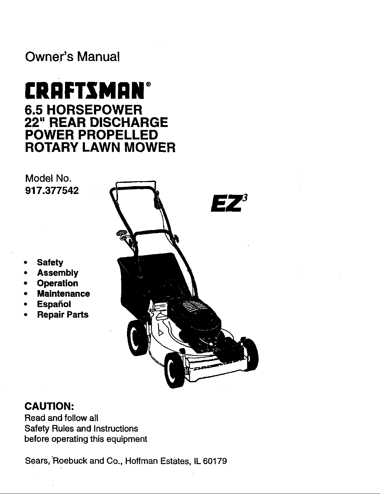
Owner's Manual
CRAFTZMAN°
6.5 HORSEPOWER
22" REAR DISCHARGE
POWER PROPELLED
ROTARY LAWN MOWER
Model No.
917.377542
• Safety
• Assembly
• Operation
• Maintenance
• Espafiol
• Repair Parts
CAUTION:
Read and follow all
Safety Rules and Instructions
before operating this equipment
Sears_:Roebuck and Co., Hoffman Estates, IL 60179
Page 2
Warranty 2 Product Specifications 11
Safety Rules 2 Service and Adjustments 14
Assembly 4 Storage 15
Operation 6 Troubleshooting 16
Maintenance Schedule 10 Repair Parts 35
Maintenance 10 Parts Ordering Back Cover
LIMITED TWO YEAR WARRANTY ON CRAFTSMAN POWER MOWER
For two years from date of purchase, when this Craftsman Lawn Mower is maintained,
lubriceted, and tuned up according to the operating and maintenance instructions in the
owner's manual, Sears will repair free of charge any defect in material or workmanship.
If this Craftsman Lawn Mower is used for commercial or rental purposes, this warranty
applies for only 90 days from the date of purchase.
This Warranty does not cover:
• Expendable items which become worn during normal use, such as rotary mower
blades, blade adapters, belts, air cleaners and spark plug.
• Repairs necessary because of operator abuse or negligence, including bent crank-
shafts and the failure to maintain the equipment according to the instructions con-
tained in the owner's manual.
Warranty service is available by returning the Craftsman power mower to the nearest
Sears Service Centar/Department in the United States. This warranty applies only while
this product is in use in the United States.
This Warranty gives you specific legal rights, and you may also have other rights which
vary from state to state.
SEARS, ROEBUCK AND CO., D/817 WA, HOFFMAN ESTATES, ILLINOIS 60179
TRAINING:
• Read this operator's manual carefully.
Become familiar with the controls and
know how to operate your mower
properly. Learn how to quickly stop
mower.
• Do notallow children to use your mower.
Never allow adults to use mower without
proper instructions.
• Keep the area of op_F_ti0_ear of all
persons, especially small children and
pets.
• Use mower only as the manufacturer
intended and as described in this manual.
• Do not operate mower if it has been
dropped or damaged in any manner.
Always have damage repaired before
using your mower.
• Do not use accessory attachments that
are not recommended by the manufac-
turer. Use of such attachments may be
hazardous.
• The blade tums when the engine is
running.
PREPARATION:
• Always thoroughly check the area to be
mowed and clear itof all stones, sticks,
wires, bones, and other foreign objects.
These objects will be thrown by the blade
and can cause severe injury.
• Always wear safety glasses or eye
shields when starting and while using
your mower.
• Dress properly. Do not operate mower
when barefoot or wearing open sandals.
Wear only solid shoes with good traction
when mowing.
• Check fuel tank before starting engine.
Do not fill gas tank indoors, when the
engine is running or when the engine is
2
Page 3
hot.Allowthe engine to cool for several
minutes before fillingthe gas tank. Clean
off any spilled gasoline before starting the
engine.
• Always make wheel height adjustments
before starting your mower. Never
attempt to do this while the engine is
running.
• Mow only in daylight or good artificial
light.
OPERATION:
• Keep your eyes and mind on your mower
and the area being cut. Do not let other
interests distract you.
• Do not mow wet or slippery grass. Never
run while operating your mower. Always
be sure of your footing -- keep a firm
hold on the handles and walk.
• Do not put hands orfeet near or under
rotating parts. Keep clear of the discharge
opening at alltimes.
• Always stop the engine whenever you
leave or are not using your mower, or
before crossing driveways, walks, roads,
and any gravel--covered areas.
• Never direct discharge of matedal toward
bystanders nor allow anyone near the
mower while you are operating it.
• Before cleaning, inspecting, or repairing
your mower, stop the engine and make
absolutely sure the blade and all moving
parts have stopped. Then disconnect the
spark plug wire and keep it away from the
spark plug to prevent accidental starting.
• Do not continue to run your mower if you
hit a foreign object. Follow the procedure
outlined above, then repair any damage
before restarting and operating you
mower.
• Do notchange the governor settings or
overspeed the engine. Engine damage or
personal injury may result.
• Do not operate your mower ifit vibrates
abnormally. Excessive vibration is an
indication of damage; stop the engine,
safely check for the cause ofvibration
and repair as required.
• Do not runthe engine indoors. Exhaust
fumes are dangerous.
• :Never cut grass by pulling the mower
towards you. Mow across the face of
slopes, never up and down or you might -
lose your footing. Do not mow exces-
sively steep slopes. Use caution when
operating the mower on uneven terrain
or when changing directions-- maintain
good footing.
• Never operate, your mower without
proper guards, plates, grass catcher or
other safety devices in place.
MAINTENANCE AND STORAGE:
• Check the blade and the engine mount-
ing bolts ofte,_ b_ure they are
tightened properly.
• Check all bolts, nuts and screws at
frequent intervals for proper tightnessto
be sure mower is in safe working
condition.
• Keep all safety devices in place and
working.
• To reduce fire hazard, keep the engine
free of grass, leaves or excessive grease
and oil.
• Check grass catcher often for deteriora-
tion and wear and replace worn bags.
Use only replacement bags that are
recommended by and comply with
specifications of the manufacturer of your
mower.
• Always keep a sharp blade on your
mower.
• Allow engine to cool before stodng in any
enclosure.
• Never store mower with fuel in the tank
inside a buildingwhere fumes may reach
an open flame or an ignition source such
as a hot water heater, space heater,
clothes dryer, etc.
CAUTION: Always disconnect spark plug
wire and place wire where it cannot
contact spark plug in order to prevent
accidental starting when setting up,
transporting, adjusting or making repairs.
WARNING
The engine exhaust from this product
contains chemicals known to the State of
California to cause cancer, birth defects,
or other reproductive harm.
3
Page 4
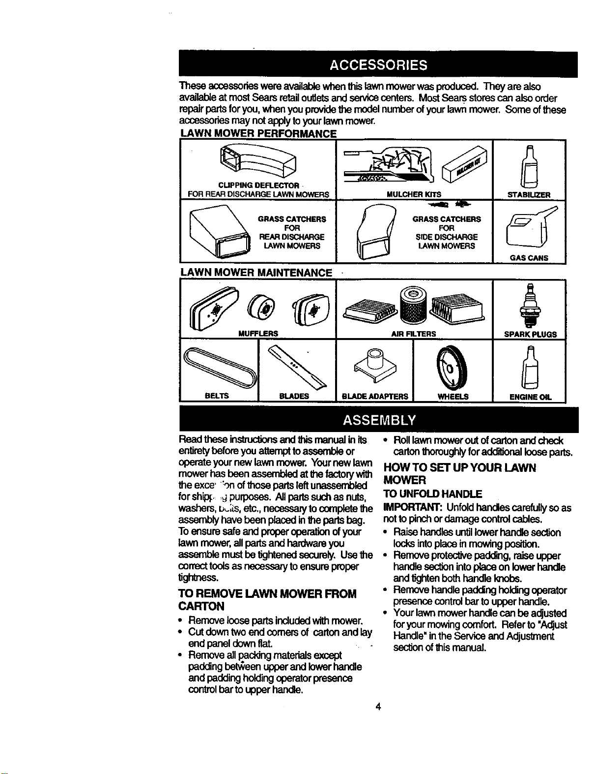
Theseaccessorieswereavailablewhenthislawnmowerwasproduced.Theyarealso
avaJ_eatmostSearsretailoutletsandservicecenters.MostSearsstores can alsoorder
repair partsfor you,when you providethe modelnumber ofyour lawn mower. Some ofthese
accessoriesmay not applytoyour lawn mower.
LAWN MOWER PERFORMANCE
rt
FOR REAR DISCHARGE LAWN MOWERS
CUPPING DEFLECTOR
GRASS CATCHERS
FOR
REAR DISCHARGE
LAWN MOWERS
LAWN MOWER MAINTENANCE
MUFFLERS
BELTS BLADES
BLADE AOAI_'TERE WHEELS
Read these instnJctionsend _s manual inits
entiretybeforeyou attempttoassemble or
operate your new lawn mower. Yournew lawn
mower has been assemUed at thefactory with
the exce' :_onofthose parts leftunassembled
for ship_. _ purposes. All partssuch as nuts,
washers, b_-;_s,etc., necessaryto complete the
assembly have been placed inthe pads beg.
To ensure safe and proper operation of your
lawn mower, all parts and hardwareyou
assemble must be tightenedsecurely. Use the
correcttools as necessary to ensure proper
tightness.
TO REMOVE LAWN MOWER FROM
CARTON
• Remove loose parts includedwith mower.
• Cut downtwo end comers of cartonand lay
end panel down fiat.
• Remove allpacking materialsexcept
padding be_een upperand lower handle
end padding holdingoperator presence
controlbarto upper handle.
MULCHER KITS
GRASS CATCHERS
FOR
SIDE DISCHARGE
LAWN MOWERS
AIR RLTERS
STABILIZER
GAS CANS
SPARK PLUGS
ENGINE Oil.
• Rolllawnmoweroutofcartonendcheck
cartonthoroughlyfor additionalloosepads.
HOW TO SET UP YOUR LAWN
MOWER
TO UNFOLD HANDLE
IMPORTANT: Unfoldhandles carefullyso as
not to pinchordamage controlcables.
• Raise handles untillower handle section
locksintoplace in mowing po,._ion.
• Remove protectivepadding, raise upper
handle sec_on intoplace on lower handle
and tightenbothhandle knobs.
• Remove handle padcing holdingoparator
presence controlbar to upper handle.
• Your lawn mower handle can be adjusted
for your mowing comfort. Refer to"Adjust
Handle" inthe Service and Adjustment
section of this manual.
4
Page 5
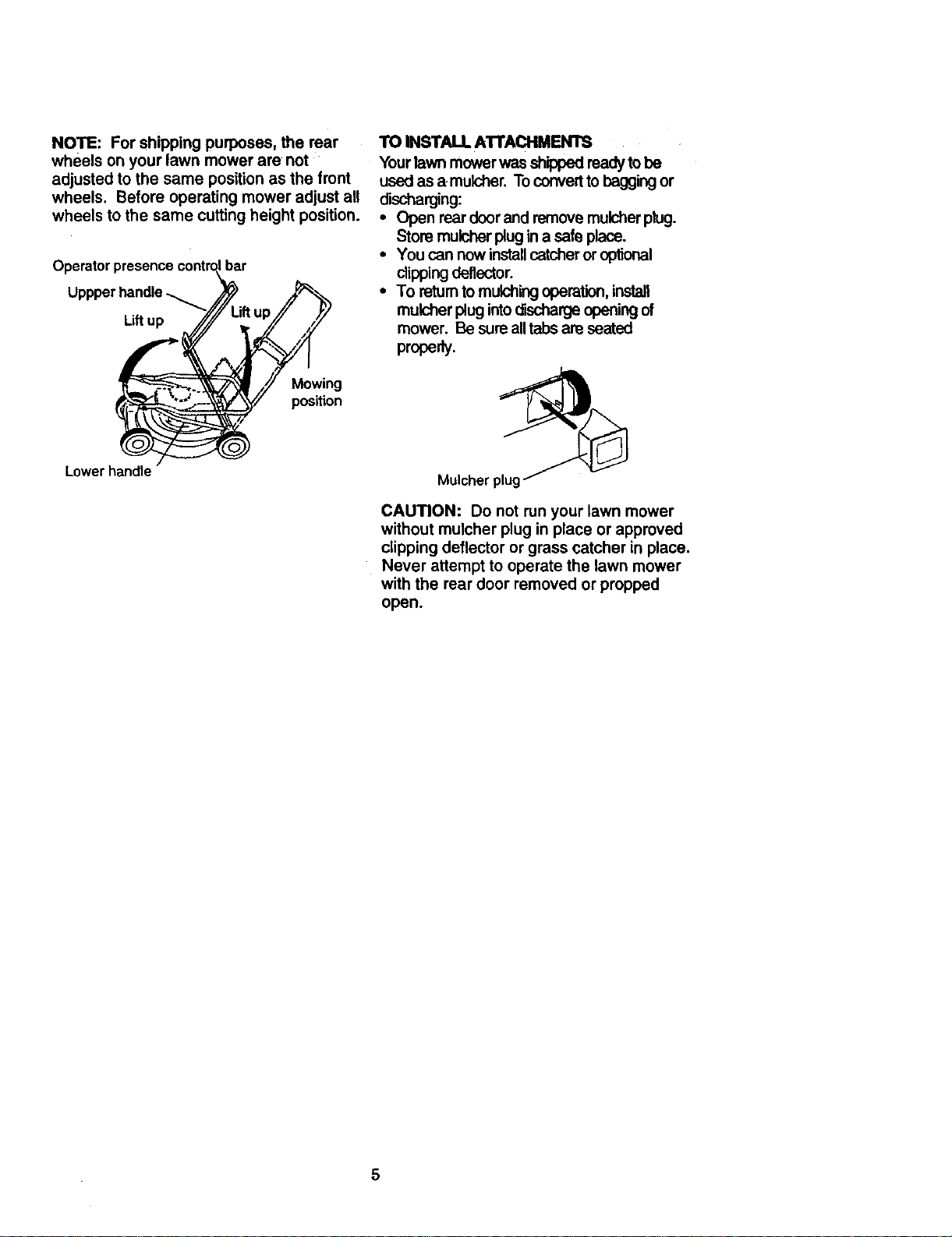
NOTE: For shipping purposes, the rear
wheels on your lawn mower are not
adjusted to the same position as the front
wheels. Before operating mower adjust all
wheels to the same cutting height position.
Operator presence contr_bar
Uppperhandle_ _/2
Liftup._._,._j.___"Uft up ,/
Mowing
position
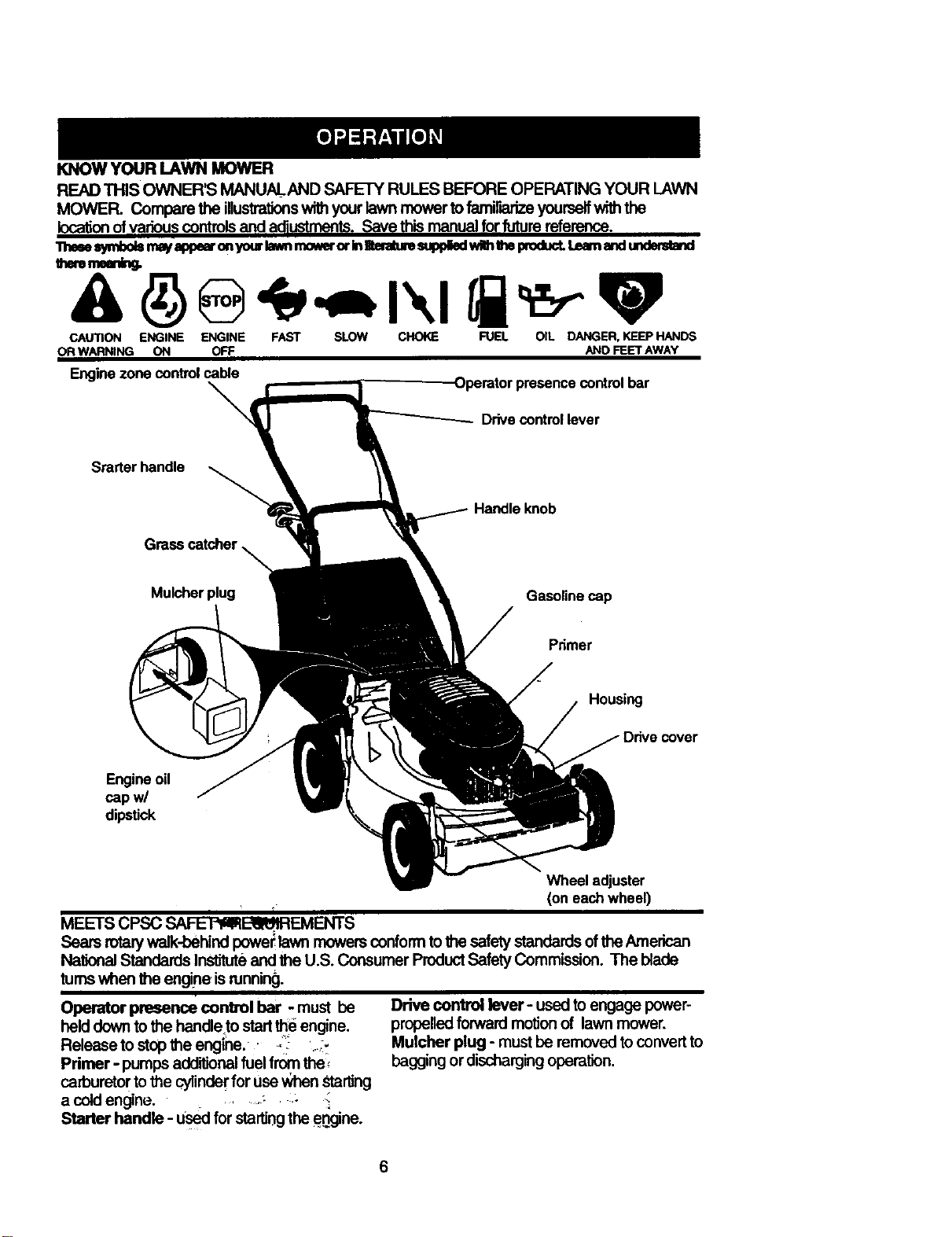
TO INSTALL AI"rACHMEN'rS
Your lawn mower was shippedreedy to be
used as a mulcher. To convertto baggingor
discharging:
• Open rear doorand remove mulcher ptug.
Store mulcher plug in a safe place.
• You can now installcatcher oroptional
dipping deflector.
• To return to mulchingoperation, install
mulcher plug intodLscharge opening of
mower. Be sureall tabs are seated
properly.
Lowerhandle
Mulcher,
CAUTION: Do not run your lawn mower
without mulcher plug inplace or approved
clipping deflector or grass catcher in place.
Never attempt to operate the lawn mower
with the rear door removed or propped
open.
5
Page 6
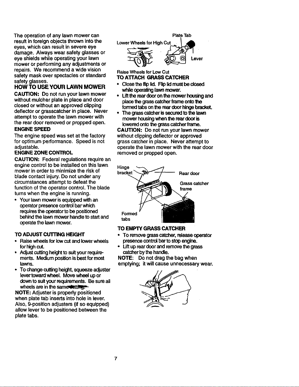
KNOWYOURLAWNMOWER
READTHISOWNER'S MANUALAND SAFETY RULES BEFORE OPERATING YOUR LAWN
MOWER. Compare the illustrationswithyour lawn mower to familiarize yourselfwiththe
locationof various controlsand adjustments. Save thismanual for future reference.
"tl_eu_/mbo_ mayappe="onyourlawnmowerorInII_raturesupplbdwilhI_epmducL_ _ _
theremaanin_
CAUTION ENGINE ENGINE FAST SLOW CHOKE FUEL OIL DANGER, KEEP HANDS
OR WARNING ON OFF AND FEET AWAY
Enginezone controlcable
controlbar
\
Drivecontrol lever
Starter handle
Mulcherplug
Engineoil
capw/
dipstick
MEETS CPSC SAFE'I'_am_EMENTS
Sears rotarywalk-behindpower lawn mowers conformto the safety standards ofthe American
National Standards Inst_Jte and the U.S. Consumer ProductSafety Commission. The blade
turnswhen the engine isnJnnin_.
Operator presence control bar - must be
held downto the hendle to start_e engine.
Releaseto stop the engine.. , : ' -_
Pdmer - pumps additionalfuel from the,
carburetorto the cylinderfor Usa_nen Starting
a cold engine. , ,: :.-
Starter handle - used for starting the e.,,ngine.
Drive control lever- used to engage power-
propelled forward motionof lawn mower.
Mulcher plug - must he removed toconvert to
baggingor dischargingoperation.
Gasoline cap
Primer
Housing
cover
Wheel adjuster
(on each wheel)
6
Page 7
Theoperationofanylawnmowercan
resultinforeignobjectsthrownintothe
eyes,whichcanresultinsevereeye
damage.Alwayswearsafetyglassesor
eyeshieldswhileoperatingyourlawn
mowerorperforminganyadjustmentsor
repairs.Werecommendawidevision
safetymaskoverspectaclesorstandard
safetyglasses,
HOWTOUSEYOURLAWNMOWER
CAUTION:Donotrunyourlawnmower
withoutmulcherplateinplaceanddoor
closedorwithoutanapprovedclipping
deflectororgrasscatcherin place.Never
attemptto operatethelawnmowerwith
thereardoorremovedorproppedopen.
ENGINESPEED
Theenginespeedwasset atthefactory
for optimum performance. Speed is not
adjustable.
ENGINE ZONE CONTROL
CAUTION: Federal regulations require an
engine control to be installed on this lawn
mower in order to minimize the risk of
blade contact injury. Do not under any
circumstances attempt to defeat the
function of the operator control. The blade
turns when the engine is running.
• Your lawn mower is equipped withan
operator presence controlbar which
requiresthe operator to be positioned
behind the lawn mower handle to start and
operatethe lawn mower.
TO ADJUST CUTTING HEIGHT
• Raise wheels for low cut and lower wheels
for high cut.
• Adjustcutting heightto suityour require-
ments. Medium positionis best formost
lawns.
• To change cuttingheight,squeeze adjuster
laver-toward wheel, Move wheel up or
downto suityour requirements. Be sure all
wheels are in the same_et'_.
NOTE: Adjuster is properly positioned
when plate tab inserts into hole in lever,
Also, 9-position adjusters (if so equipped)
allow lever to be positioned between the
plate tabs.
PlateTab
t
LowerWheelsforHighCut _.._
_ " _Lever
Raise Wheels for LowCut
TO ATTACH GRASS CATCHER
• Close the flip lid. Rip lidmust be cloeed
while operatinglawn mower.
• Liftthe reer door onthe mower housing and
place the grasscatcher frame ontothe
formedtabs on the rear door hinge bracket.
• The grasscatcher is cured to the lawn
mower housingwhen the rear door is
lowered onto the grasscatcher frame.
CAUTION: Do not run your lawn mower
without clipping deflector or approved
grass catcher in place. Never attempt to
operate the lawn mower with the rear door
removed or propped open.
Hinge
Rear door
Grass catcher
frame
Formed
tabs
TO EMPTY GRASS CATCHER
• To remove grasscatcher, release operator
presence controlbarto stop engine.
• Liftup rear doorand remove the grass
catcher by the handle.
NOTE: Do not drag the bag when
emptying; it will cause unnecessary wear.
7
Page 8
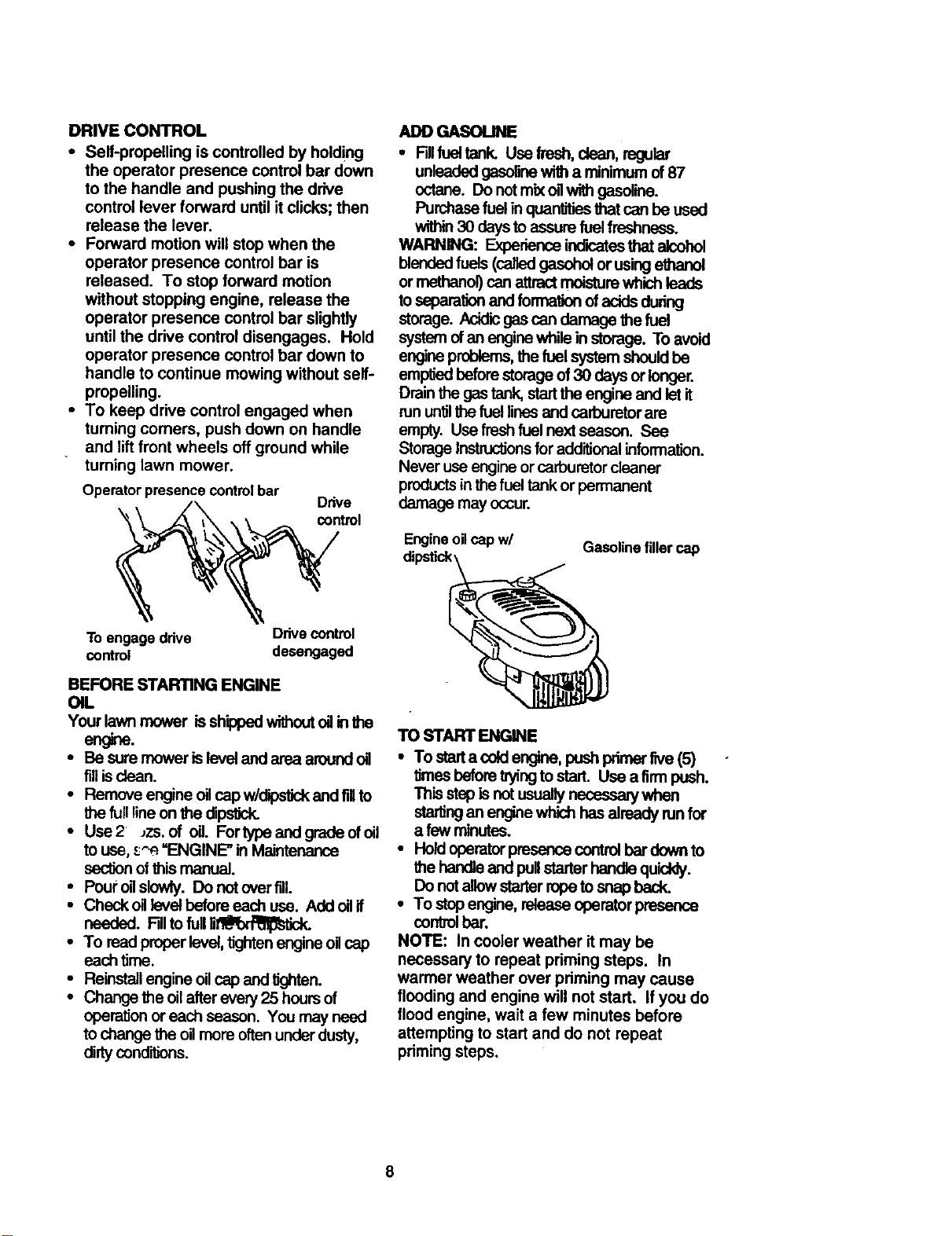
DRIVE CONTROL
• Seif-propelling is controlled by hold!ng
the operator presence control bar down
to the handle and pushing the drive
control lever forward until it clicks; then
release the lever.
• Forward motion will stop when the
operator presence control bar is
released. To stop forward motion
without stopping engine, release the
operator presence control bar slightly
until the drive control disengages. Hold
operator presence control bar down to
handle to continue mowing without self-
propelling.
• To keep drive control engaged when
turning comers, push down on handle
and lift front wheels off ground while
tuming lawn mower.
Operator presence controlbar
"_ control
Drive
ADD GASOI.INE
• Fdlfueltank.Use fresh, dean, regular
unleaded gasolinewith a minimum of87
octane. Do notmix oliwith gasoline.
Purchasefuel in quantitiesthat can be used
within30 days to assure fuelfreshness.
WARNING: Expedence indk:atesthat alcohol
blendedfuels (calledgasohol or using
or methanol) can attractmoisturewhich leads
toseparationand formationof acids dudng
storage. Acidic gascan damage the fuel
system of an engine while instorage. To avo'_l
engine problems,the fuel system should be
emptied before storage of 30 days or longer.
Drain the gas tank, startthe engine and let it
run untilthefuel linesand carburetorare
empty. Use fresh fuel next season. See
Storage Instructionsfor additionalinformation.
Never use engine or carburetor cleaner
productsin thefuel tank or permanent
damage may occur.
Engineoilcapw/
Gasolinefillercap
To engage drive Drivecontrol
control desengaged
BEFORE STARTING ENGINE
OIL
Your lawn mower is shippedwithoutoilinthe
en .
• Be sure mower is level and area around oil
filiis clean.
• Remove engine oilcap w/dipstickand fillto
the full lineon the dipstick.
• Use2 Jzs.of oil. Fortypeandgradaofoil
to use, s^_.=ENGINE" in Maintenance
sectionofthis manual.
• Pour oHslowly. Do not over fill.
• Check oil level before each use. Add oil if
needed. Fillto full_.
• To read proper level, tightenengine oilcap
each time.
• Reinstall engine oil cap and tighten.
• Change the oil after every 25 hoursof
operaUonor each season. You may need
to change the oilmore oftenunder dusty,
dirty conditions.
TO START ENGINE
• To sterta cold engine, push primerfive (5)
times beforeWing to start. Use afirm push.
Thisstep is not usuagynecessary when
stertingan engine which has already run for
a few minutes.
• Hold operatorpresence control bar down to
the handleand pullstarter handle quickly.
Do notallow starter rope to snap beck.
• To stop engine, release operatorpresence
control bar.
NOTE: In cooler weather it may be
necessary to repeat priming steps. In
warmer weather over pdming may cause
flooding and engine will not start. If you do
flood engine, wait a few minutes before
attempting to start and do not repeat
priming steps.
Page 9
MOWINGTIPS
• Under certain conditions, such as very
tall grass, it may be necessary to raise
the height of cut to reduce pushing effort
and to keep from overloading the engine
and leaving clumps of grass clippings. It
may also be necessary to reduce
ground speed and/or run the lawn
mower over the area a second time.
• For extremely heavy cutting, reduce the
width of cut by overlapping previously
cut path and mow slowly.
• For better grass bagging and most
cutting conditions, the engine speed
should be set in the fast position.
• When using a rear discharge lawn
mower in moist, heavy grass, clumps of
cut grass may not enter the grass
catcher. Reduce ground speed (push-
ing speed) and/or run the lawn mower
over the area a second time.
• If a trail of clippings is left on the right
side of a rear discharge mower, mow in
a clockwise direction with a small
overlap to collect the clippings on the
next pass.
• Pores in cloth grass catchers can
become filled with dirt and dust with use
and catchers will collect less grass. To
prevent this, regularly hose catcher off
with water and let dry before using.
• Keep top of engine around starter clear
and clean of grass clippings and chaff.
This will help engine air flow and extend
engine life.
MULCHING MOWING .TIPS
IMPORTANT: Forbest performance, keep
mower housingfree ofbuilt-upgrass and
trash. See "Cleaning" in Maintenance section
ofthis manual.
• The spacialmulchingblade willrecutthe
grass clippingsmany limes and reduce
them in size so that as they fail ontothe
lawn they willdisperse intothe grass and
not be noticed. Also, the mulched grass will
biodegradequicldy to pro_de nutrientsfor
the lawn. Alwaysmulch with your highest
engine (blade) speed as this willprovide the
best recuttingactionof the blades.
• Avoid curlingyourlawnwhen it is wet. Wet
grass tends to form dumps and interferes
withthe mulchingaction. The best time to
mowyour lawn is the Party afternoon. At
this time the grass has dried and the newly
cut area will not be exposed to the direct
sun.
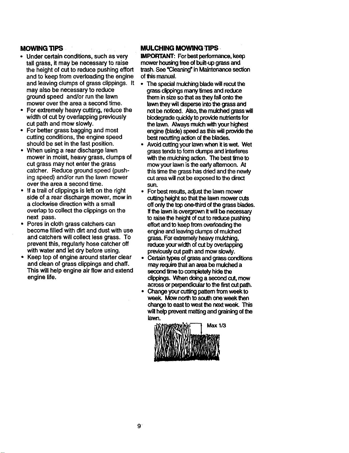
• For best results, adjust the lawn mower
cutting height so that the lawn mower cuts
off only the top one-third of the grass blades.
If the lawn is overgrown it will be necessary
to raise the height of cut to reduce pushing
effort and to keep from overloading the
engine and leaving clumps of mulched
grass. Forextremely heavy mulching,
reduce yourwidth ofcutby overlapping
previously cutpath and mow slewly.
• Certain typas ofgrassand grass conditions
may requirethat an area be mulched a
seceed tJrnetocomplately hide the
cl'q0pings.Whan doinga secondcut, mow
across or perpendicular to the firstcut path.
• Change your curlingpattern from week to
week. Mow north to south one week then
change to east to west the next week. This
w_llhelp prevent matting and graining of the
lawn.
/3
9
Page 10

MA,NTENANCESCHEDULE
o_ o_ _ _ _ :_o_,
CheckforLooseFasteners l/ M
Clean/Inspect Grass Catcher
M CleanLawnMowerClean UnderDriveCover
W (Power-PropelledMowers) IVlCheckdrive aeys
R Check/Shamen/RepZaceBlade I/=
Lu_k_UonCha. V' V'
CleanBallery/Recharge
IE_c st_MowersI V" V'4
E jCheckErmineOilLevel i/
N
G !CleanAirNiter
I Inspect Muffler If
N Cleanor ReplaceSparkPlug
Replace Nr FilterPaperCartridge i,/z
1 - Change mine o_m wh_m operadingund_ a hemlyk_d or in high ambient temp_atur_.
2 - Se_ice moreollln when operatingIndi_ _ du_y i:=ndiEcns.
3 - _ biadee m_e o_en _ _ in_nW zoiL
4. Ctm_ge4e i_wr_ _t _€l o#m4_cr_.
GENERAL RECOMMENDATIONS
The warranty on this lawn mower does not
cover items that have been subjected to
operator abuse or negligence. To receive
full value from the warranty, operator must
maintain mower as instructed in this
manual.
Some adjustments will need to be made
periodically to properly maintain your unit.
All adjustments in the Service and
Adjustments section of this manual should
be checked at least once each season.
• Once a year, replace the spark plug,
replace air filter element and check
blade for wear. A new spark plug and
clean/new air filter element assures
proper air-fuel mixtur.ei_nelzbeJpsyour
engine run better and last longer.
• Follow the maintenance schedule in this
manual.
BEFORE EACH USE
• Check engine oil level.
• Check for loose fasteners.
LUBRICATION
Keep unit well lubricated (See 'LUBRICA-
TION CHART').
(_) Wheel
(_) Handlebracket
('_ Referto Maintenance"ENGINE"
IMPORTANT: Do noto_orgrease plastic
wheel bearings.Viscous lubricantswillattract
dustand dirtthat willshorten the lifeofthe self
lubricatingbearings. If you feel they mustbe
lubricated,use only a dry,powdered graphite
type lubricantsparingly.
10
v'
LUBRICATION CHART
adjuster (_ Engine
oil
Brake
spring
_ Rear doorbracket
hinge
mounting pin
SprayU,r t
section.
Page 11

PRODUCT SPECIFICATIONS
MODEL NUMBER 917.377542
SERIAL NUMBER
DATE OF PURCHASE
HORSEPOWER: 6.5
DISPLACEMENT: 11.5 CU. IN.
GASOLINE CAPACITY/TYPE: 1.6 QUARTS
UNLEADED REGULAR
OIL TYPE (API-SF/SG/SH): SAE 30 (ABOVE 32°1=)
SAE 5W-30 (BELOW 32°F)
OIL CAPACITY: 20 OZS.
SPARK PLUG (GAP: .030") CHAMPION RJ19LM OR J19LM
VALVE CLEARANCE: INTAKE: .004 - ,008
EXHAUST: .004 - .008
SOLID STATE IGNITION
AIR GAP: .0125 IN.
BLADE BOLT TORQUE: 35-40 FT. LBS.
The model and serial numbers will be found on a decal attached to the rear of the
lawn mower housing,Record both serial number and date of purchase in space
provided above.
LAWN MOWER
Always observe safety ruleswhen performing
any maintenance.
TIRES
• Keep tires free of gasoline, oil, or insect
controlchemicals wh'_h can harm rubber.
• Avok:lstumps, stones,deep ruts, sharp
objectsand other hazards that may cause
tiredamage.
BLADE CARE
For best results,mower blade must be kept
sharp. Replace bent or damaged blades.
TO REMOVE BLADE
• Disconnectspark plug wire from spark plug
and place wire where it1_n_'t_me in
contact with spark plug.
• Turn lawn mower on its side. Make sureair
filterand carburetor are up.
• Use a wood blockbetween blade and
mower housingto prevent blade from
tuming when removing blade bolt.
• Protect your hands with gloves and/or wrap
blade with heavy cloth.
• Remove blade bolt by turningcounter-
clockwise. Use a 9/16" box or open-end
wrench.
• Remove blade and attaching hardware
(bolt,lockwasher and hardened washer).
NOTE: Remove the blade adapter and
check the key inside hub of blade adapter.
The key must be in good condition to work
properly. Replace adapter if damaged.
TO REPLACE BLADE
• Positionthe bladeadapter on the engine
crankshaft. Be sure key in adapter and
crankshaft keywayare aligned.
• Positionblade on the blade adapter aligning
the two (2) holes in the blade withthe raised
lugson the adapter.
• Be sure the trailingedge ofblade (opposite
sharpedge) is up towardthe engine.
• Installthe blade belt withthe lockwasher
and hardened washer intoblade adapter
and crankshaft.
• Use block ofwood between blade and lawn
mower housingand tightenthe blade belt,
turningdockwise.
• The recommended tighteningtorque is35-
40ft. bs.
IMPORTANT: Bladebelt isgrade 8 heat
treated.
Page 12

TOSHARPENBLADE
NOTE: We do not recommend sharpening
blade - but if you do, be sure the blade
is balanced.
Care should be taken to keep the blade
balanced. An unbalanced blade will
cause eventual damage to lawn mower or
entre.
• The blade can be sharpened with a file or
on a grinding wheel. Do not attempt to
sharpen while on the mower.
• To check blade balance, drivea nailintoa
beam orwall. Leave ahout one inch of the
straightnail exposed. Place center hole of
blade over the haad of the nail If blade is
balanced, itshouldremain ina horizontal
_. Ifeitherend of the blade moves
downward, sharpen the heavy end untilthe
blade is balanced.
Blade Crank shaft
keyway
Blade
bolt
Lock Blade
washer Hardened edge adapter
washer
GRASS CATCHER
• The grass catcher may be hosed wi_
water, but must be dry when used.
• ChecF your grass catcheroftenfor damage
or de,+,_oration. Through normal use itwig
wear.It.catcherneedsrspledng,replace
only with a manufacturer approved
_nt catcher. Give the lawn mower
model numberwben_rde=_.
DRIVE WHEELS
Check front drive wheels each time before
you mow to be sure they move freely.
The wheels not turning freely means trash,
grass cuttings, etc. are in the drive wheel
area and must be cleaned to free drive
wheels.
If necessary to clean the drive wheels,
check both front Wheels.
• Remove hLlbcaps, hairpin cotters and
washers.
•- Remove wheels from wheel adjusters.
shaft
• Remove any trash or grass cuttings from
inside the dust cover, pinion and/or drive
wheel gear teeth.
• Put wheels back inplace.
• If after cleaning, the drive wheels do not
turn freely, contact your nearest
authorized service center.
GEAR CASE
• TO keep your drive system working
properly, the gear case and area around
the drive should be kept clean and free
of trash build-up. Clean under the drive
cover twice a season.
• The gear case is filled with lubricant to
the proper level at the factory. The only
time the lubricant needs attention is if
service has been performed on the gear
case.
• If lubricant is required, use only Texaco
Starplex Premium 1 Grease, Part No.
750355. Do not substitute.
ENGINE
LUBRICATION
Useonlyhicjhqualitydetorgentoilratedwith
API sewice dassificaUon SF,SG, or SH.
SelecttheoiPsSAE viscositygrade accord-
ingtoyour expected operatingtemperature.
SAEVI_CC_tTY GP_DES
NOTE: Although mulli-viscosfly oils
(5W30,10W30etc.)improvestarlingin
cold wea_r, these mu_viscosity oils will
result in increased oil consump'don when
used above 32°F. Check your engine oil
level more frequen_ to avoid possible
engine damage from running low on oH.
Change after the first25 hours of operation at
leastonce a year If the lawn mower is not used
for25 hoursin one year.
Check the crankcase oillevel before starting
the engine and after each five (5) hours of
corCdnuoususe.Tighten Ollplugsecurely each
8rr_ you checkthe oHlevel.
TO CHANGE ENGINE OIL
NOTE: Before tipping lawn mower to drain
oil, drain fuel tank by running engine until
fuel tank is empty.
• Disconnect spark pl_ wirefrom spark plug
and place wire where itcannot come in
contactw_hsparkp_g.
12
Page 13

• Remove engine oilcap; lay aside on a claan
surface.
• Tip lawn mower on itsside as shown and
drain oil intoa suitablecontainer. Rock lawn
mower back and forthto remove any oil
trapped inside ofengine.
• Wipe off any spilledoilon lawn mower and
on side ofengine,
• Fill engine with oil. Fillonlytothe "FULL"
line on the dipstick. DO NOT overfill.
• Replace engine oilcap.
• Reconnect spark plug wire to spark plug.
Container
AIR FILTER
Your engine will not run properly and may
be damaged by using a dirty air filter.
Replace the air filter every year, more
often if you mow in very dusty, dirty
conditions. Do not wash air filter.
TO CHANGE AIR FILTER
• Remove the air filter by turning clock-
wise to the stop and pull away from
collar.
• Remove filter from inside of cover.
• Clean the inside of the cover and the
collar to remove any dirt accumulation.
• Insert new filter into cover.
• Put air filter cover and filter into collar
aligning the tab with the slot.
• Push in on cover and turn counterclock-
wise to tighten,
Collar
MUFFLER
Inspectend replaca conoded mulfleras it
couldcreate a firehazard and/or damage.
SPARK PLUG
Change your spark plug each year to make
yourengine starteasier and runbetter. Set
spark pluggap at .030 inch.
CLEANING
IMPORTANT: For best performance, keep
mower housing free of built-up grass and
trash. Clean the underside of your mower
after each use.
CAUTION: Disconnect spark plug wire
from spark plug and place wire where it
cannot come in contact with the spark
plug.
• "rum lawn mower on its side, Make sure air
filterand carburetorare up. Clean the
undersideof yourlawn mower by scraping
to removebuild-up of grass and trash.
• Clean engine often to keep trash from
accumulating. A dogged engine runs hotter
and shortens engine life.
• Keep finishedsurfacesand wheels free of
allgasoline, oil,etc.
• We do not recommend using a garden
hose to clean lawn mower unless the
electricalsystem, muffler,airfilter and
carburetorare covered to keep water out.
Water in engine can resultin shortened
engine life.
CLEAN UNDER DRIVE COVER
Clean underddve cover at leasttwiea a
season. Sorape undersideof cover withputty
knifeor similartcol to remove any build-upof
trash or grass on undersideof drive cover.
Slot
Air Filter Tab
"rum
to
Remove
"rum
Counter-
Air Filter Clockwise to
Cover _ghten
13
Page 14

CAUTION:BEFOREPERFORMINGANY
SERVICEORADJUSTMENTS:
• Release control bar.
• Make sure the blade and all moving
parts have completely stopped,
• Disconnect spark plug wire from spark
plug and place where it cannot come
in contact with plug.
LAWN MOWER
TO ADJUST cu'n'ING HEIGHT
See "TO ADJUST cuTrlNG HEIGHT" in the
Operation sectionof this manual.
REAR DEFLECTOR
The mar deflector, attached between the rear
wheels of your lawn mower, isprovidedto
minimizethe possibilitythat objectswill be
thrown out the roarof the lawn mower into the
operator'smowingposition, ffthe roar
deflectorbecomes damaged, it,shouldbe
TO REMOVE/REPLACE DRIVE BELT
• Remove drivecover. Remove beltby
pushing clownon gear case pulleyand roll
belt off.
• Turn lawn mower on itsside with carburetor
and fuel cap up,
• Remove blade.
• Remove debrisshield.
• Remove beltfrom engine pulleyon
crankshaft.
• Installnew belt by reversingabove steps.
• Always use factoryapproved belt to assure
fitand long life.
• Remove the starterropegu'_efrom the
upper handla.
• Remove hairpincotters.
• Disconnectthe lowerhandle fromthe
handle brackets.
• Turn the handle over and reassemble the
hairpincotters that have been removed.
• Reassemble the starterrope guide.
• Reassemble the controlsand the operator
presence controlbar tothe upper handle.
CAUTION: The operator presence control
bar must pivot freely to permit blade brake
engagement when control bar is released.
Do not over tighten the fasteners holding
the controls to the upper handle.
• TO change from medium lowto high
position only the upper handle sectionwill
have to be fumed over.
• To change from medium lowto low position,
only the lower handle sectionwill have to be
turned over.
Shippingposition
Medium low
mhigh
Yourlawn mower handte_an_:"raised or
lowered for your mowing comfort. Four (4)
positionsam available: high,medium high,
medium low and low. Handles are shipped
mounted in the medium low position.
• To change from medium lowto medium
high position,the upperand lower handle
sections willhave to be turned over.
• Remove the cable dips.
• Remove {hecontrolsand operatorpresence
control bar from the upper handle.
Lower handle
\
Squeeze to
remove
Hairpinclil Handle
bracket
14
Page 15

Immediately prepare your lawn mower for
storageat the end of the season or if the unit
willnot be used for 30 days or more.
LAWN MOWER
When lawn mower is to be stored for a period
of time, clean itthoroughly, remove all dirt,
grease, leaves, etc. Store ina dean, dry area.
• Clean enlJrelawn mower (See "CLEANING"
in the Maintenance section ofthis manual).
• Lubricateas shown in the Maintenance
sectionofthis manual.
• Be sure that ellnuts,bolts, screws, and pins
are securelyfastened. Inspect moving
partsfor damage, breakage and wear.
Replace if necessary.
• Touch upell rustedor chipped paint
surfaces;send lightlybefore painting.
HANDLE
You can fold your lawn mower handle for
storage.
• Squeeze the bottom ends ofthe lower
handle toward each other untilthe lower
handle clears the handlebracket,then
move handle forward.
• Loosen upper handle mountingbolts
enough to allow upper handle tobe folded
back.
IMPORTANT: When folding the handlefor
storage or transportation,be sureto fold the
handle as shown oryou any damage the
controlcables.
• When setting up your handle from the
storage position,the lower handle will
automaticallylock intothe mowingposition.
Lower
handle
Squeeze to fold
bracket
Operatorpresence controlbar
Upper
Foldfoward
for storage
Fold
backward
Lower Mowing
handle position
ENGINE
FUEL SYSTEM
IMPORTANT: Itis importantto prevent gum
depositsfromforming in essant'Blfuel system
partssuch as carburetor,f fuel filter, fuel bose
or tank during storage. Also,experience
indicatesthat alcohol blendedfuels ( called
gasoholor usingethanol or methanol) can
attract moisturewhichleads to separation and
formation ofacids duringstorage. Acidicgas
can damage the fuel systemof an engine
while in storage.
• Drain the fuel tank.
• Start the engine and letitrun untilthe fuel
linesand carburetor are empty.
• Never use engine or carburetor cleaner
productsin the fuel tank or permanent
damage may occur.
• Use fresh fuel next season.
NOTE: Fuel stabilizer is an acceptable
alternative in minimizing the formation of
fuel gum deposits during storage. Add
stabilizer to gasoline in fuel tank or storage
container. Always follow the mix ratio
found on stabilizer container. Run engine
at least 10 minutes after adding stabilizer
to allow the stabilizer to reach the
carburetor. Do not drain the gas tank and
carburetor if using fuel stabilizer.
cotter
15
Page 16

ENGINEOIL
Drainoil(withenginewarm)andreplecewith
cleanengine oil. (See "ENGINE" inthe
Maintenance sectionofthis manual).
CYLINDER
• Remove sparkplug.
• Pour one ounce (29 ml) of oilthroughspark
plugholeintocyr._der.
• Pull starterhendle slowlya few _rnes to
distributeoil.
• Repleca wi_ new spark plug.
OTHER
• Do not store gasolinefromone season to
another.
• Replace your gasoline can if yourcan starts
to _ Rust and/or dirtinyour gasolinewill
cause problems.
• If _, storeyour unitindoorsand cover
_to give protectionfrom dust and cfrL
• Cover your unitwith a suitableprotective
cover that doesnot retainmoisture. Do not
use plastic. Plas_ cannot breathe which
allowscondensationto form and willcause
yourunitto rust.
IMPORTANT: Never cover mower while
engine and exhaust areas am_ll warm.
CAUTION: Never store the lawn mower
with gasoline in the tank inside a building
where fumes may reach an open flame or
spark. Allow the engine to cool before
storing in any enclosure.
TROUBLESHOOTING CHART
.....P.ROBLEM
Does notstart
CAUSE
• I_ty airliter.
• Outo_luel.
• Sta_ fuel.
• Waler_nfuel;
• spa p gwire
• Badsp p ug.
• Loose bledQor broken blade
adapter.
• Control bar in released
• Control bar defective.
CORRECTION
• Clean/replace air filter.
• Fi, fual tank.
• Drein tank and refillwith
freshclean fuel
• Drain fuel tankand
carburetor and retgltank
withfresh gasoline.
• Connect wire to plug.
• Re_acespark_ug.
• TK:jhtenblade bolt or
replaceblade adapter.
• Depress controlbar to
handle.
• Replace controlbar.
16
Page 17

TROUBLESHOOTING CHART
PROBLEM
[Loss of power
Poor cut- uneven
CAUSE
• Rear of lawn mower housing
or cuffingblade dragging
in heaW grass.
• Cuttingtoo much grass.
• Dirtyair filter.
• Buildupof grass, leaves,
and trash under mower.
• Too much oil in engine.
• Walking speed too fast.
• Worn, bent or loose blade.
• Wheel heights uneven.
• Buildup ofgrass, leaves
and trash under mower.
CORRECTION
• Set to "Higher Cut"
pos'nion.
• Set to "Higher Cut_
position.
• Clean/replace air filter,
• Clean underside of mower
housing.
• Check oil level.
• Cut at slowerwalking
speed.
• Replace blade.'nghten
blade bolt.
• Set all wheels at same
height
• Clean underside of
mower housing.
Excessive
vibration
Starter rope hard
to pull
Grass.catcher
not filling (if so
equipped)
Hard to push
• Worn, bent or loose blade.
• Bent engine crankshaft.
• Engine flywheel brake ison
when controlbar is released.
• Bent engine crankshaft.
• Blade adapter broken.
• Blade dragging in grass.
• Cutting heighttoo low.
• Uft on blade wom off.
_,atlbe_ notventing air.
• Grass istoo highor wheel
height istoo low.
• Rear oflawn mower
housing orblade dragging
in grass.
• Grass catcher too full.
• Handle heightpositionnot
rightforyou.
• Replace blade. TK3hten
bladebolt.
• Contactan authorized
servicecenter.
• Depress controlbar to
upper handle before
pullingstarterrope.
• Contact an authorized
service canter.
• Replace blade adapter.
• Move lawn mower tocut
gress or tohard surlace
tostartengine,
• Raise cuttingheight.
• Rep cab de.
•. Clean grass catcher,
• Flaisecuttingheight,
• Raise rearof lawn mower
housing one (1) seUJng
higher.
• Empty grass catcher.
• Adjusthandle height to
suit.
17
Page 18

ROTARY LAWN MOWER - - MODEL NO. 917.377542
GEAR CASE ASSEMBLY PART NUMBER 702511
KEY
NO.
17490416
2
137055X004
3
137053
4
57072
6
48373
77881
137051
PART
NO.
KEY PART
DESCRIPTION NO. NO.
TappingScrew 114-20x 9 137074
1-1/4 10 57079
EngagementBracket 11 131484
_r 12 700343
_ 13 86447
Gear Case Halves Kit 14 137050
(includesKeyNos. 4, 5, 15 750436X
and 7) 16 750369
Bearing 17 12000003
WormShaft 18 850848
19 81585X004
NOTE: All component dimensions given
in U.S. inches. 1 inch = 25.4 mm
35
DESCRIPTION
DriveShaft
HardenedWasher
ClutchYoke
Bushing
Plug
HelicalGear
ClutchJaw
Grease
E-Ring
Hi-ProKey
SpringBracket
Page 19

ROTARY LAWN MOWER MODEL NUMBER 917.377542
13
¢.o
c_
22
-23
41
27
28
Page 20

ROTARY LAWN MOWER MODEL NUMBER 917.377542
oJ
KEY PART
NO. NO.
1 165451X479
2 156577
4 150425
5 66426
6 136376
8 145793
9 151023
10 128415
11 150050
12 STD512505
13 77400
14 156374X479
15 700365X479
16 133190X479
17 140661X479
18 63601
20 140540
22 85543
23 87677
25 83923
27 151158
28 142748
29 62335
30 t 45935X004
31 701037
32 700331X004
34 146630
35 700325X007
37 150078
39 151512X479
40 151511X479
KEY PART
DESCRIPTION NO. NO. DESCRIPTION
Upper Handle
EngineZone ControlCable
lcherPlug
re11e
ndla Knob
ontrolBar
ear DoorKit
opRivet
Self TappingScrew #10-24 x 5/8
HexTappingScreww/Sems 1/4-20 x 1/2
Hubcap
Back Plate
Side Baffle
DischargeBaffle
Rear Baffle
KepsLocknut1/4-20
Rear Skirt
EnginePulley
Hi-Pro Key #505
klaxFlangeNut
Wheel
ShoulderBolt 3/8-16 x 1
BellevilleWasher
AxleArm
Selector Knob
Selector Spring
Spacer
Wheel AdjustingBracket
ThreadCutting Screwwlsema 5/16-18 x 3/4
HandleBracketAssembly(Left)
HandleBracketAssembly (Right)
41 150406
44 161769
46 851514
47 157101
48 851074
49 850263
50 851084
51 165548
52 85463
55 761592
56 88652
57 51793
58 157081X479
59 131959
61 132001
62 134612
64 .o.o_-
- - 161059
- - 166495
Availableaccessoriesnotincludedwith lawnmower:
. - 71 33303 ClippingDeflector
. - 71 33623 Gas Can (2.5 gal.)
. - 71 33500 Fuel Stabilizer
- - 71 33300 SAE 30W Oil(20 oz.)
- - 71 33417 DustShield
- - 71 33316 MowerCover
- - 71 33723 HighWheel Kit
HexHead Thread RoilingScrew 3/8-16 x 1-1/8
LawnMowerHousing(Incl.Key#14, 15, 51)
BladeAdapter
Blade22"
HardenedWasher
HelicalWasher 3/8-24 x 1o3/8Gr, 8
HexHead Machine Screw 3/8-24 x 1-3/6 Gr, 8
FrontBaffle
DangerDecal
Locknut 3/8-16
HingeScrew 1/4`20 x 1-1/4
HairpinCotter
LowerHandle
HandleBolt
Rope Guide
DebrisShield
Engine - (See Breakdown)
Tecumseh Model No.996502
WarningDecal (Not Shown)
Owner'sManual(EnglisWSpenlsh)
Page 21

(,o
oo
'ROTARY LAWN MOWER MODEL NUMBER 917.377542
14
Page 22

ROTARY LAWN MOWER MODEL NUMBER 917.377542
co
cO
KEY
NO.
10
11
12
13
14
15
16
2
3
4
5
6
8
9
PART
NO.
145755
48385
751152
158755
146527
150495
77400
145212
88446
151156
12000058
137054
88080
88118
67725
KEY PART
DESCRIPTION
ontrolCable Assembly 26 143603
_a_nntrolHead Kit
knut#10-24 28 154990
Head MachineScrew 1/4 x 2.12 31 132010
V-Belt 33 48386
SpringRetainer 35 151521
Hubcap 36 702511
FlangedNut 37 137090
Nylon Bushing 38 63601
Wheel& Tire Assembly 40 75192
E-Ring 41 151520
Pinion 53 144747
DustCover 54 154870
FeltWasher 55_ 86012
Washer I/2 x 1-1/2 x .134 57 144748
NO. NO. DESCRIPTION
18 701037
32 137052
SelectorKnob
PanHead TappingScrew #10-24 x 2-3/4
DriveCover
HexFlange Nut
DdvePulley
DdveControlCable Kit
WheelAdjusterAssembly(Left)
Gear Case Assembly
Spring
Nut
Spring
WheelAdjusterAssembly(Right)
FrameThroat
GrassbagAssembly
DdveshaftCover
GrassbagTube
Page 23

CRAFTSMAN 4-CYCLE ENGINE MODEL NO. 143.996502
.390
4OO
130
120
119
125
182
19
186
239
178
238 25O
310
245
40
Page 24

CRAFTSMAN 4-CYCLE ENGINE
KEY PART
NO. NO. DESCRIPTION
37266
2
26727
6
33734
36557
7
12 36775
12A 36558
12B 36694
14 28277
15 30589
16 34839A
17 31335
18 651018
19
36281
326OO
2O
3O
35801
4O
40027
40028
41
4OO25
4O026
4OOO6
42
40OO7
43
20381
45
36777
46
32610A
48
27241
5O
36778
52
29914
69
35261
70
34311E
72
30572
73
28833
75
27897
8O
30574A
81
30590A
82
30591
83
3O588A
86
65O488
89
611004
9O
611112
92
65O815
93
650816
100
34443B
101
610118
103
651007
11o
37047
119
36787
12o
36825
125
37288
126
37289
Cylinder(Incl.2,20 & 172 36784
156) 174 3O2OO
DowelPin 178 29752
BreatherElement
BreatherAss'y. (Ind. 6 & 182 6201
12A) 184 26756
BreatherTube
BreatherCover &Tuhe 185 36785
(Ind. 12B) 186 32653
BreatherTube Elbow 189 650839
Washer 191 3O559A
GovernorRod (Ind. 14)
GovernorLever 195 610973
GovernorLeverClamp 207 34336
Screw,TorxT-15, 8-32 x 216 33086
19/64" 223 650451
ExtensionSpdng 224 36786
OilSeal 238 650932
Crankshaft 239 34338
Piston,Pin & RingSet 241 36919
(Std.) 245 36905
Piston,Pin& RingSet 250 36920
(.010" OS) 260 36980
Piston& Pin Ass'y.(Std.) 261 30200
(Incl.43) 262 650831
Piston& PinAss'y.(.010" 263A 36921
OS) (Incl. 43) 275 36790
RingSet (Std.) 277 650988
RingSet (.010" OB) 285 35000A
PistonPin Retaining 287 650926
Ring 290 29774
ConnectingRodAss'y. 292 26460
(Incl.46) 298 28763
ConnectingRodBelt 300 36916
Valve Lifter
Camshaft(MCR) 301 36246
OilPumpAss'y. 305 35647
• MountingFlangeGasket 306 36996
MountingFlange(Incl.72 307 35499
thin83,306) 309 650562
OilDrain Plug(ind. 73) 310 35648
DrainPlugGasket 313 34080
OilSeal 347 651038
Gevemer Shaft 370A 36261
Washer 370C 37199
GovernorGear Ass'y. 380 640174
(Ind. 81) 390 590739
Govemor Spool 400 36792B
Screw, 1/4-20 x 1-1/4"
FlywheelKey
Flywheel
BellevilioWasher
_tgnltion
SparkPlug Cover 416 36085
Screw,Ton(T-15, 10-24
x 15/16" 417 650821
GroundWire
• CylinderHead Gasket 900
Cylinder Head
ExhaustValve(Std.) 900_--
(incl.151)
IntakeValve (Std.) (Incl.
151)
130
135
15o
151-
151A
169
6021A
35395
31672
31673
40017
36783
Screw,5/16-18 x 1-1/2"
ResistorSparkPlug
(FU19LM)
ValveSpring
ValveSpdngCap
IntakeValve Seal
• ValveCoverGasket 41
MODEL NO. 143.996502
KEY
NO.
PART
NO. DESCRIPTION
Valve Cover
Screw,10-24 x 9/16"
Nut& LockWasher, 114-
28
Screw,1/4-28 x 7/8"
• CarburetorTo Intake
PipeGasket
IntakePipe
GovernerLink
Screw, 1/4-2Ox 3/8"
S.E. BrakeBracket (Ind.
195)
Terminal
ThrottleLink
R.P.M. AdjustingLever
Screw, 1/4-20 x 1"
* IntakePipe Gasket
Screw, 10-32 x 49/64"
• Air Cleaner Gasket
Air Cleaner Collar
AirCleaner Filter
AirCleaner Cover
BlowerHousing
Screw, 10-24 x 9/16"
Screw, 114-20x 1/2"
StarterGdll
Muffler
Screw, 1/4-20 x 2-5/16"
StarterCup
Screw,6-32 x 21164"
Fuel Line
Fuel LineClamp
Screw, 10-32 x 35/64"
FuelTank(Ind. 292 &
301)
FuelCap
Oil FillTube
• "O"-Ring
"O"-Ring
Screw, 10-32 x 1/2"
Dipstick
Spacer
Screw, 10-32 x 51/64"
Lubrica_onDecal
Pdmer Decal
Carburetor(Incl. 184)
RewindStarter
Gasket Set(loci.hems
Marked" inNotes) Ind.
Part #'s26756 (1),28833
(1), 34338 (1), 36783
(1),36755 (1),36787 (1),
36832 (1), 36996 (I),
37130 (1)
SparkArrestorKit(Ind.
417)(Optlonel)
Screw, 16-32 x 1/2"
(Optional)
ReplacementEngine
NONE
ReplacementS/B
750832, orderfrom 71-
999
RPM High 2900 to 3200
NOTE: This engine could have been built with
59070 starter.
NOTE: All component dimensions given In U.S.
inches 1 inch = 25,4 mm
Page 25

CRAFTSMAN 4-CYCLE ENGINE MODEL NO. 143.996502
J:)_S7
KEY PART
NO. NO.
---- 640174
1 631615
2 631767
4 631184
5 631183
6 640070
7 650506
16 631807
17 651028
18 630766
20 640018
20A 64O053
25 631867
27 6310_4
28m_r,6._B=_
29 631028
30 631021
31 631022
35 36045A
36 64OO80
36A 632766
37 632547
40 640175
44 27110A
47 630748
48 631027
48A 631027
60 632760
DESCRIPTION
Carburetor(Incl.184 of EngineParts List)
Throt_eShaft & LeverAssembly
ThrottleReturnSpring
• Dust SealWasher
• Dust Seal (Throttle)
Throttle Shutter
* ShutterScrew
FuelF_ting
Throttle Crack Screw/idleSpeed Screw
TensionSpdng
IdleRestdctorScrew
Idle RestdctorScrewCap
FloatBowl
• FloatShaft
Float
• FloatBowl=Ct'Ring
• InletNeedle, Seat, & Clip(Ind. 31)
Spring Clip
Primer BullYRetainerRing
Main Nozzle Tube
CarburetorTube
• "O"Ring,MainNozzle Tube
HighSpeedBowlNut
BowlNutWasher
• Welch Plug,IdleMixtureWelt
"Welch Plug,AtmosphericVent
* Welch Plug
Repairkit(Incl. ItemsMarked" inNotes)
42
Page 26

CRAFTSMAN 4-CYCLE ENGINE MODEL NO. 143.996502
,;-,
--S
m 11
KEY
NO.
11
12
13
1
2
3
4
5
6
7
8
PART
NO.
598702
598599A
590600
59O696
590601
590697
59O698
590699
590700
590703
590535
590701
DESCRIPTION
RecoilStarter
SpringPin (Incl.4)
Washer
Retainer
Washer
BrakeSwing
StarterDog
DogSpring
Pulley& RewindSpdng
Ass'y.
StarterHousingAss'y.
(40 degree grommet)
StarterRope( 98" X 9/
64" dia.)
StarterHandle
V--14
KEY
NO.
3
6
7
8
11
/
!1 I! -7
12
13
14
PART
NO.
590739
5987_
590616
590617
590618A
590638
598_5
598701
590760
DESCRIPTION
RewindStarter
Retainer
StarterDog
DogSpdng
Pulley & RewindSpring
Ass_
StarterHousing Ass'y
(40 degreegrommet)
StarterRope(Length98"
x9/64"dia.)
StarterHandle
SpringC,p
43
Page 27

Forthe repair or replacement parts you need
delivered directly to your home
Call 7 am - 7 pm, 7 days a week
1-800-366-PART
(1-800-366-7278)
Para ordenar piezas con entrega a
domicilio - 1-800-659-7084
For in-house major brand repair service
Call 24 hours a day, 7 days a week
1-800-4-REPAIR
(1-800-473-7274)
Para pedir servicio de reparaci6n a
domicilio - 1-800-676-5811
For the location of a Sears Parts and
Repair Center in your area
Call 24 hours a day, 7 days a week
1-800-488-1222
For information on purchasing a Sears
Maintenance Agreement or to inquire
about an existing Agreement
Call 9 am - 5 pro, Monday-Saturday
1-800-827-6655
When requesting service or ordedng
parts, always provide the following
information:
• Product Type • Part Number
• Model Number • Part Description
m mlnmmmmmm
mmmmm(
SEARS
Amenca's Repaor Specialists
166495 09.14.98 " VB Printed in U.S.A.
 Loading...