

Page 1
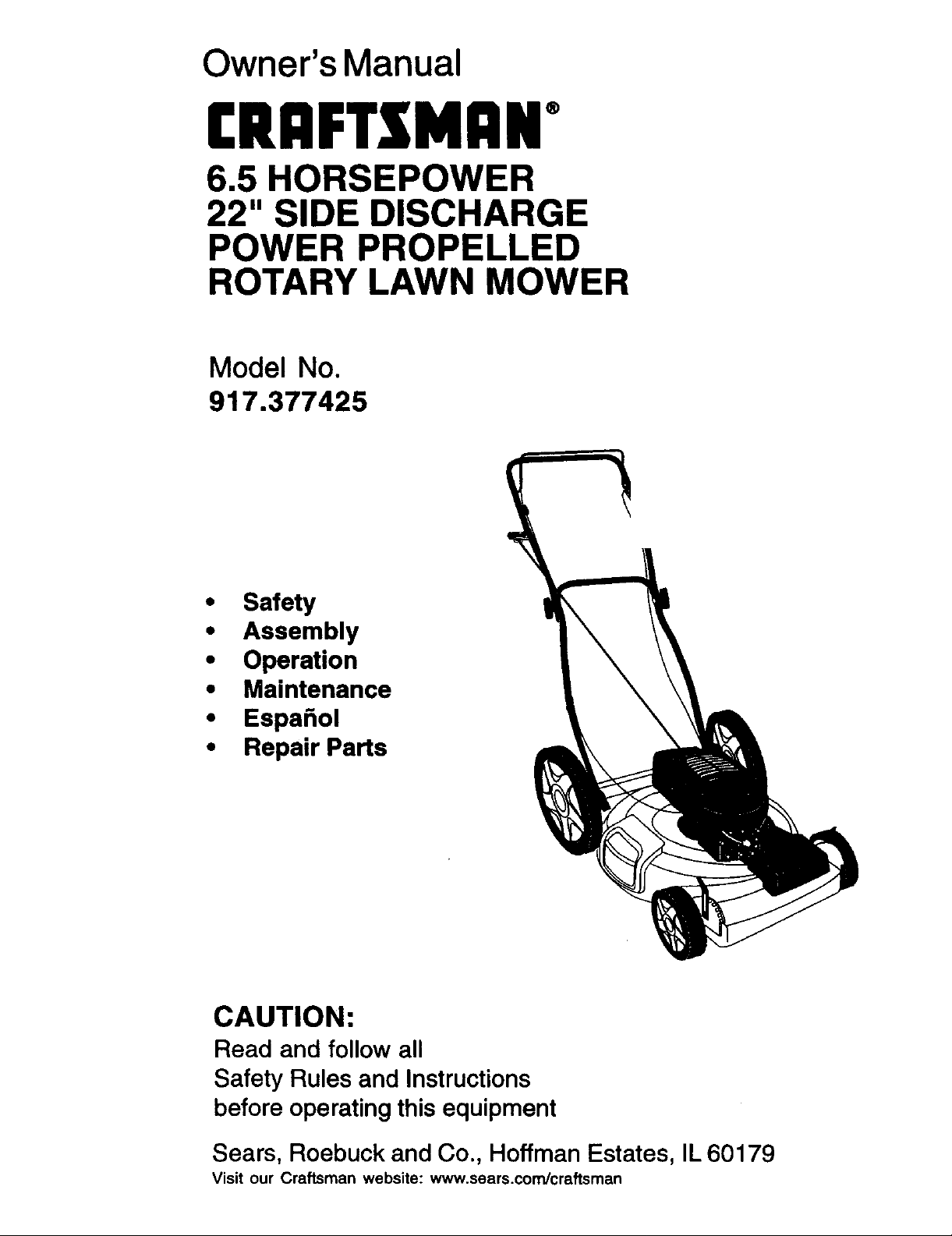
Owner's Manual
CRAFTS[MAN+
6.5 HORSEPOWER
22" SIDE DISCHARGE
POWER PROPELLED
ROTARY LAWN MOWER
Model No
917.377425
• Safety
• Assembly
• Operation
• Maintenance
• Espa_ol
• Repair Parts
CAUTION:
Read and follow all
Safety Rules and Instructions
before operating this equipment
Sears, Roebuck and Co., Hoffman Estates, IL 60179
Visit our Craftsman website: www.sears.com/craftsman
Page 2
Warranty 2 Product Specifications 10
Safety Rules 2 Service and Adjustments 13
Assembly 4 Storage 14
Operation 5 Troubleshooting 16
Maintenance Schedule 9 Repair Parts 35
Maintenance 9 Parts Ordering Back Cover
LIMITED TWO YEAR WARRANTY ON CRAFTSMAN POWER MOWER
For two years from date of purchase, when this Craftsman Lawn Mower is maintained,
lubricated, and tuned up according to the operating and maintenance instructions in
the owner's manual, Sears will repair free of charge any defect in material or workman-
ship.
If this Craftsman Lawn Mower is used for commercial or rental purposes, this warranty
applies for only 90 days from the date of purchase.
This Warranty does not cover:
• Expendable items which become worn during normal use, such as rotary mower
blades, blade adapters, belts, air cleaners and spark plug.
• Repairs necessary because of operator abuse or negligence, including bent
crankshafts and the failure to maintain the equipment according to the instructions
contained in the owner's manual.
Warranty service is available by returning the Craftsman power mower to the nearest
Sears Service Center/Department in the United States. This warranty applies only
while this product is in use in the United States.
This Warranty gives you specific legal rights, and you may also have other rights which
vary from state to state.
SEARS, ROEBUCKAND CO., D/817 WA, HOFFMAN ESTATES, ILLINOIS 60179
Safety standards require operator
presence controls to minimize the risk of
injury. Your unit is equipped with such
controls. Do not attempt to defeat the
function of the operator presence controls
under any circumstancas.
TRAINING:
• Read this operator's manual carefully.
Become familiar with the controls and
know how to operate your mower
propedy. Learn how to quicldy stop
mower.
• DO not allow children to use your mower.
Never allow adults to use mower without
proper instructions.
• Keep the area of operation clear of all
persons, especially small children and
pets.
• Use mower only as the manufacturer
intended and as described in this
manual.
• Do not operate mower if it has been
dropped or damaged in any manner.
Always have damage repaired before
using your mower.
• Do not use accessory attachments that
are not recommended by the manufac-
turer. Use of such attachments may be
hazardous.
• The blade turns when the engine is
running.
PREPARATION:
• Always thoroughly check the area to be
mowed and clear it of all stones, sticks,
wires, bones, and other foreign objects.
These objects will be thrown by the
blade and can cause severe injury.
• Always wear safety glasses or eye
shields when starting and while using
your mower.
2
Page 3
• Dross properly. Do not operate mower
when barefoot or weadng open sandals.
Wear only solid shoes with good traction
when mowing.
• Check fuel tank before starting engine.
Do not fill gas tank indoors, when the
engine is running or when the engine is
hot. Allow the engine to cool for several
minutes before filling the gas tank. Clean
off any spilled gasoline before starting
the engine.
• Always make wheel height adjustments
before starting your mower. Never
attempt to do this while the engine is
running.
• Mow only in daylight or good artificial
light.
OPERATION:
• Keep your eyes and mind on your
mower and the area being cut. Do not let
other interests distract you.
• Do not mow wet or slippery grass. Never
run while operating your mower. Always
be sure of your footing -- keep a firm
hold on the handles and walk.
• Do not put hands or feet near or under
rotating pads. Keep clear of the dis-
charge opening at all times.
• Always stop the engine whenever you
leave or are not using your mower, or
before crossing driveways, walks, roads,
and any gravel---covered areas.
• Never direct discharge of material
toward bystanders nor allow anyone
near the mower while you are operating
it.
• Before cleaning, inspecting, or repairing
your mower, stop the engine and make
absolutely sure the blade and all moving
parts have stopped. Then disconnect the
spark plug wire and keep it away from
the spark plug to prevent accidental
starting.
• Do not continue to run your mower if you
hit a foreign object. Follow the procedure
outlined above, then repair any damage
before restarting and operating you
mower.
• Do not change the governor settings or
overspeed the engine. Engine damage
or personal injury may result.
• Do not operate your mower if it vibrates
abnormally. Excessive vibration is an
indication of damage; step the engine,
safely check for the cause of vibration
and repair as required.
• Do not run the engine indoors. Exhaust
fumes are dangerous.
• Never cut grass by pulling the mower
towards you. Mow across the face of
slopes, never up and down or you
might lose your footing. Do not mow
excessively steep slopes. Use caution
when operating the mower on uneven
terrain or when changing directions
maintain good footing.
• Never operate your mower without
proper guards, plates, grass catcher or
other safety devices in place.
MAINTENANCE AND STORAGE:
• Check the blade and the engine
mounting belts often to be sure they are
tightened propedy.
• Check all bolts, nuts and screws at
frequent intervals for proper tightness to
be sure mower is in safe working
condition.
• Keep all safety devices in place and
working.
• To reduce fire hazard, keep the engine
free of grass, leaves or excessive
grease and oil.
• Check grass catcher often for deteriora-
tion and wear and replace wom bags.
Use only replacement bags that are
recommended by and comply with
specifications of the manufacturer of
your mower.
• Always keep a sharp blade on your
mower.
• Allow engine tocool before stodng in
any enclosure.
• Never store mower with fuel in the tank
inside a building where fumes may
reach an open flame or an ignition
source such as a hot water heater,
space heater, clothes dryer, etc.
ALOOk for this symbol to point out
important safety precautions, it means
CAUTIONffI BECOMEALERT!!! YOUR
SAFETY IS INVOLVED.
ACAUTION: Always disconnect spark
plug wire and place wire where it cannot
contact spark plug in order to prevent
accidental starting when setting up,
transporting, adjusting or making repairs.
AWARNING
The engine exhaust from this product
contains chemicals known to the State of
California to cause cancer, birth defects,
or other reproductive harm.
3
Page 4
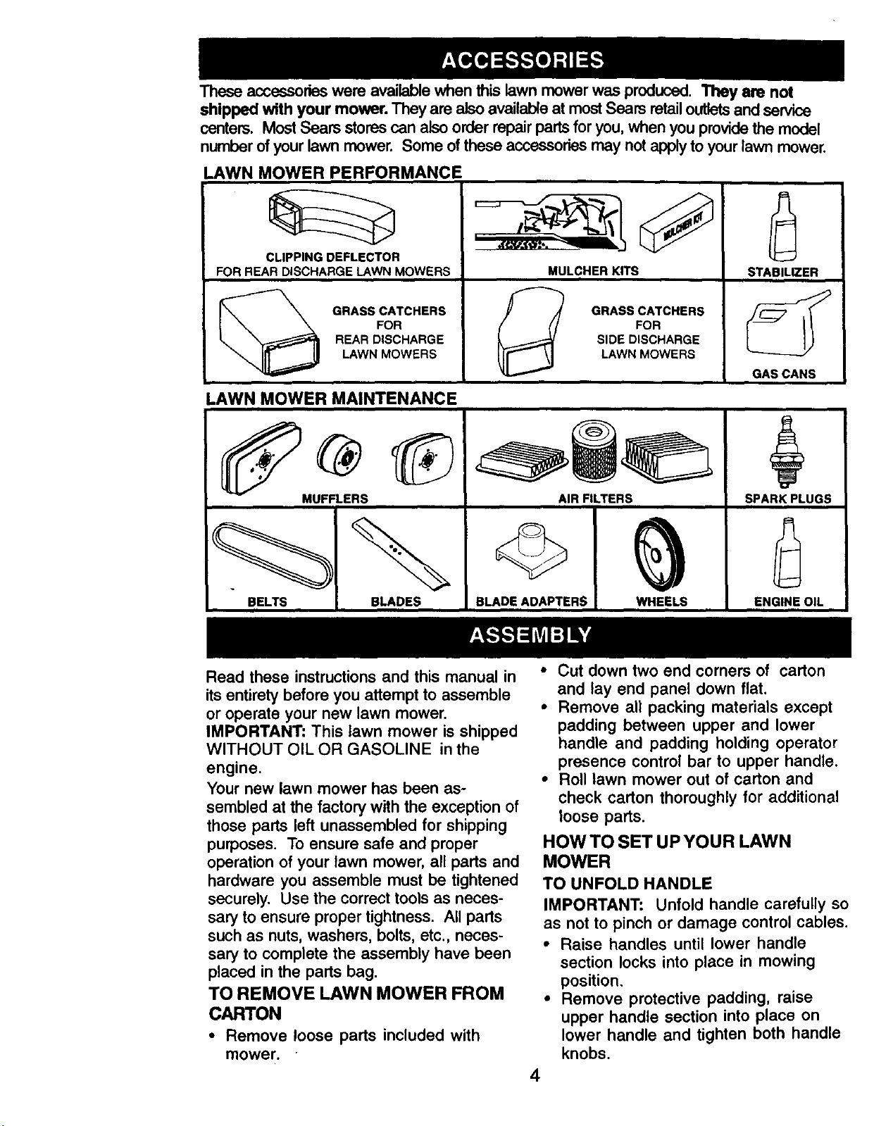
Theseaccessorieswere available when this lawn mower was produced. They am not
shipped with your mower. They are also available at most Sears retailoutletsand sewice
centers. Most Sears stores can also order repair parts for you, when you providethe model
number of your lawn mower. Some of these accessories may not applyto your lawn mower.
LAWN MOWER PERFORMANCE
CLIPPING DEFLECTOR
FOR REAR DISCHARGE LAWN MOWERS MULCHER KITS
GRASS CATCHERS
FOR
REAR DISCHARGE
LAWN MOWERS
SIDE DISCHARGE
GRASS CATCHERS
LAWN MOWERS
LAWN MOWER MAINTENANCE
FOR
STABILIZER
GAS CANS
MUFFLERS AIR FILTERS
BELTS BLADES
BLADE ADAPTERS
Read these instructions and this manual in
its entirety before you attempt to assemble
or operate your new lawn mower.
IMPORTANT: This lawn mower is shipped
WITHOUT OIL OR GASOLINE in the
engine.
Your new lawn mower has been as-
sembled at the facton/with the exception of
those parts left unassembled for shipping
purposes. To ensure safe and proper
operation of your lawn mower, all parts and
hardware you assemble must be tightened
securely. Use the correct tools as neces-
sary to ensure proper tightness. All parts
such as nuts, washers, bolts, etc., neces-
sary to complete the assembly have been
placed in the parts bag.
TO REMOVE LAWN MOWER FROM
CARTON
• Remove loose parts included with
mower.
SPARK PLUGS
WHEELS
ENGINE OIL
• Cut down two end corners of carton
and lay end panel down flat.
• Remove all packing materials except
padding between upper and lower
handle and padding holding operator
presence control bar to upper handle.
• Roll lawn mower out of carton and
check carton thoroughly for additional
loose parts.
HOW TO SET UP YOUR LAWN
MOWER
TO UNFOLD HANDLE
IMPORTANT: Unfold handle carefully so
as not to pinch or damage control cables.
• Raise handles until lower handle
section locks into place in mowing
position.
• Remove protective padding, raise
upper handle section into place on
lower handle and tighten both handle
knobs.
4
Page 5
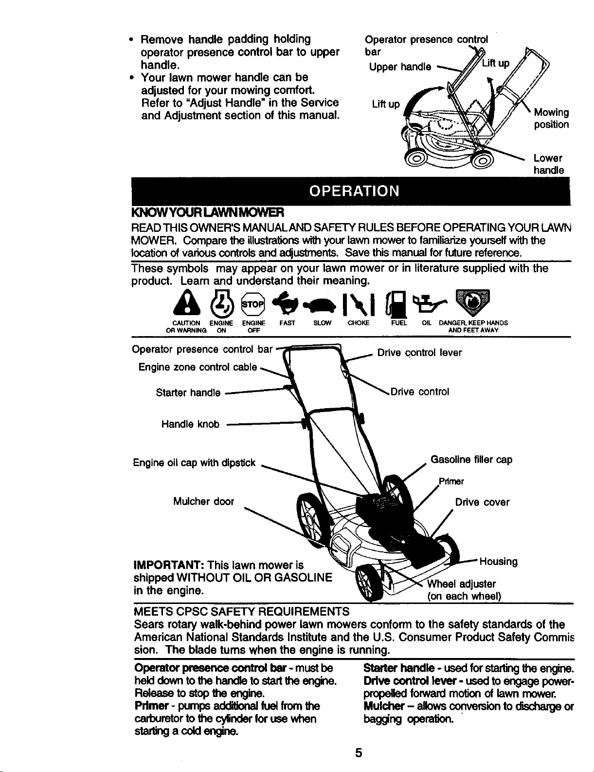
• Remove handle padding holding
operator presence control bar to upper
handle.
Operator presence control
bar
Upper handle
• Your lawn mower handle can be
adjusted for your mowing comfort.
Refer to =Adjust Handle" in the Service
Lift up
and Adjustment section of this manual.
position
Lowe r
handle
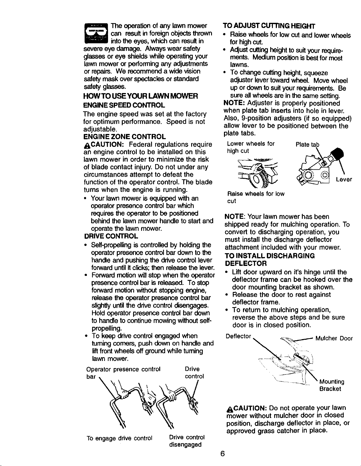
KNOWYOURLAWNMOWER
READ THIS OWNER'S MANUALAND SAFETY RULES BEFORE OPERATING YOUR LAWN
MOWER. Compare the illustrations with your lawn mower to familiarize yourself with the
location of various controlsand adjustments. Save this manual for future reference.
These symbols may appear on your lawn mower or in literature supplied with the
product. Learn and understand their meaning.
CAUTION ENGINE ENGINE FAST SLOW CHOKE FUEL OIL DANGER, KEEP HANDS
OR WARNING ON OFF AND FEET AWAY
Operator presence control
Engine zone control cable
Starter handle control
Handle knob
Engine oil cap with dipstick
Mulcher door
Drive control lever
Gasoline filler cap
Pdmer
Drive cover
IMPORTANT: This Dawnmower is
shipped WITHOUT OIL OR GASOLINE
in the engine.
iNheel adjuster
(on each wheel)
MEETS CPSC SAFETY REQUIREMENTS
Sears rotary walk-behind power lawn mowers conform to the safety standards of the
American National Standards Institute and the U.S. Consumer Product Safety Commis
sion. The blade turns when the engine is running.
Operator presence control bar- must be
held down to the handla to startthe engine.
Release to stop the engine.
Primer - pumps additionalfuelfrom the
carburetor to the cylinderfor use when
_ acoldengine.
Starter handle - usedforstartingthe engine.
Drive controllever - usedto angage power-
propelledforwardmotionof lawn mower.
Mulcher- allowsconvers'_ontodfschargeor
bag_ng operaUon.
5
Page 6
can resultin foreign objects thrown
The operation of any lawn mower
intothe eyes, which can result in
severe eye damage. Always wear safety
glasses or eye shields while operating your
lawn mower or performing any adjustments
or repairs. We recommend a wide vision
safety mask over spectacles or standard
safetyglasses.
HOW TO USE YOUR LAWN MOWER
ENGINE SPEED CONTROL
The engine speed was set at the factory
for optimum performance. Speed is not
adjustable.
ENGINE ZONE CONTROL
ACAUTION: Federal regulations require
an engine control to be installed on this
lawn mower in order to minimize the risk
of blade contact injury. Do not under any
circumstances attempt to defeat the
function of the operator control. The blade
turns when the engine is running.
• Your lawn mower is equipped with an
operator presence control bar which
requires the operator to be positioned
behind the lawn mower handle to start and
operate the lawn mower.
DRIVE CONTROL
• Self-propelling is controlled by holding the
operator presence control bar down to the
handle and pushing the drive control lever
forward until itclicks; then release thelever.
• Forward motion will stop when the operator
presence control bar is released. To stop
forward motion without stopping engine,
release the operator presence control bar
slightlyuntilthe drive control disengeges.
Hold operator presence control bar down
to handle to continue mowing without self-
propelling.
• To keep drive control engaged when
tuming corners, push down on handle and
liftfrontwheels off ground while tuming
lawn mower,
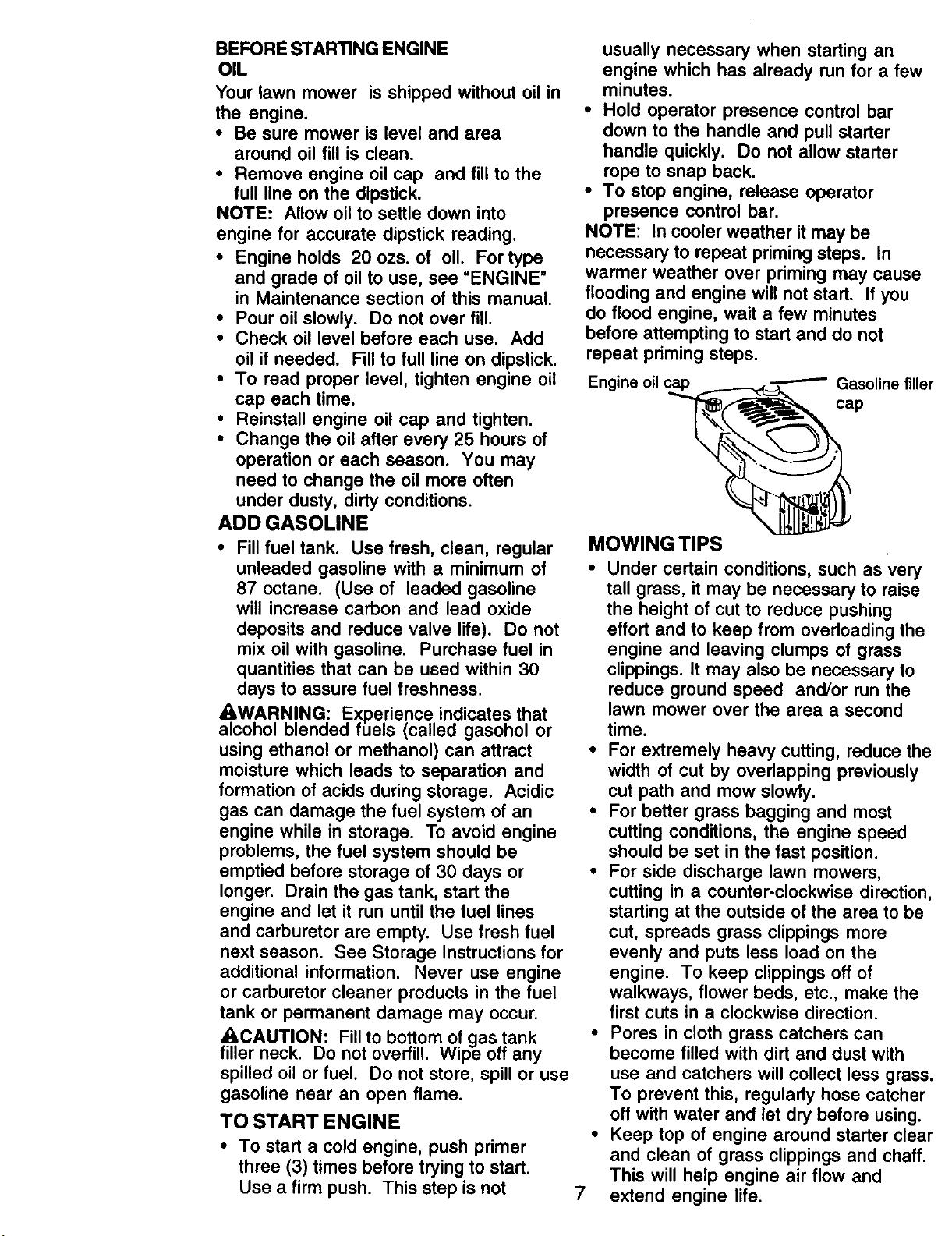
TO ADJUST CUTTING HEIGHT
• Raise wheals for low cutand lower wheels
for high cut.
• Adjustcutting heightto suityour require-
merits. Medium positionis bestfor most
lawns.
• To change cutting height, squeeze
adjuster lever toward wheel. Move wheel
up or down to suit your requirements. Be
sure all wheels are in the same setting.
NOTE: Adjuster is properly positioned
when plate tab inserts into hole in lever.
Also, 9-position adjusters (if so equipped)
allow lever to be positioned between the
plate tabs.
Lower wheels for Plate tab
high cut
Lever
Raise wheels for low
cut
NOTE: Your lawn mower has been
shipped ready for mulching operation. To
convert to discharging operation, you
must install the discharge deflector
attachment included with your mower.
TO INSTALL DISCHARGING
DEFLECTOR
• Lift door upward on it's hinge until the
deflector frame can be hooked over the
door mounting bracket as shown.
• Release the door to rest against
deflector frame.
• To return to mulching operation,
reverse the above steps and be sure
door is in closed position.
Deflector
•_ Mulcher Door
\
Operator presence control Drive
bar _ control
To engage ddve control
Drive control
disengaged
Bracket
_:_CAUTION: Do not operate your lawn
mower without mulcher door in closed
position, discharge deflector in place, or
approved grass catcher in place.
6
Page 7
BEFORE STARTING ENGINE
OIL
Your lawn mower is shipped without oil in
the engine.
• Be sure mower is level and area
around oil fill is clean.
• Remove engine oil cap and fill to the
full line on the dipstick.
NOTE: Allow oil to settle down into
engine for accurate dipstick reading.
• Engine holds 20 ozs. of oil. For type
and grade of oil to use, see =ENGINE"
in Maintenance section of this manual.
• Pour oil slowly. Do not over fill.
• Check oil level before each use. Add
oil if needed. Fill to full line on dipstick.
• To read proper level, tighten engine oil
cap each time.
• Reinstall engine oil cap and tighten.
• Change the oil after every 25 hours of
operation or each season. You may
need to change the oil more often
under dusty, dirty conditions.
ADD GASOLINE
• Fill fuel tank. Use fresh, clean, regular
unleaded gasoline with a minimum of
87 octane. (Use of leaded gasoline
will increase carbon and lead oxide
deposits and reduce valve life). Do not
mix oil with gasoline. Purchase fuel in
quantities that can be used within 30
days to assure fuel freshness.
_cWhARNING; Experience indicates that
ol blenood fueJs _calleo gasonol or
using ethanol or methanol) can attract
moisture which leads to separation and
formation of acids during storage. Acidic
gas can damage the fuel system of an
engine while in storage. To avoid engine
problems, the fuel system should be
emptied before storage of 30 days or
longer. Drain the gas tank, start the
engine and let it run until the fuel lines
and carburetor are empty. Use fresh fuel
next season. See Storage Instructions for
additional information. Never use engine
or carburetor cleaner products in the fuel
tank or permanent damage may occur.
f._,.,CAUTION: Fill to bosom of gas.tank
iHerneck. Do not ovenill. Wipe on any
spilled oil or fuel. Do not store, spill or use
gasoline near an open flame.
TO START ENGINE
• To start a cold engine, push primer
three (3) times before trying to start.
Use a firm push. This step is not
usually necessary when starting an
engine which has already run for a few
minutes.
• Hold operator presence control bar
down to the handle and pull starter
handle quickly. Do not allow starter
rope to snap back.
• To stop engine, release operator
presence control bar.
NOTE: In cooler weather it may be
necessary to repeat priming steps. In
warmer weather over priming may cause
flooding and engine will not start. If you
do flood engine, wait a few minutes
before attempting to start and do not
repeat priming steps.
MOWING TIPS
• Under certain conditions, such as very
tall grass, it may be necessary to raise
the height of cut to reduce pushing
effort and to keep from overloading the
engine and leaving clumps of grass
clippings. It may also be necessary to
reduce ground speed and/or run the
lawn mower over the area a second
time.
• For extremely heavy cutting, reduce the
width of cut by overlapping previously
cut path and mow slowly.
• For better grass bagging and most
cutting conditions, the engine speed
should be set in the fast position.
• For side discharge lawn mowers,
cutting in a counter-clockwise direction,
starting at the outside of the area to be
cut, spreads grass clippings more
evenly and puts less load on the
engine. To keep clippings off of
walkways, flower beds, etc., make the
first cuts in a clockwise direction.
• Pores in cloth grass catchers can
become filled with dirt and dust with
use and catchers will collect less grass.
To prevent this, regularly hose catcher
off with water and let dry before using.
• Keep top of engine around starter clear
and clean of grass clippings and chaff.
This will help engine air flow and
7
extend engine life.
Page 8
MULCHINGMOWINGTIPS
IMPORTANT: For best performance, keep
mower housing free of built-up grass and
trash. See =Cleaning" in MAINTENANCE
section of this manual.
• The speciaJmulching blade will recut the
grass clippings many times and reduce
them in size so that as they fall onto the
lawn they willdisperse into the grass and
notbe noticed. Also, the mulched grass
will biodegrade quickly to provide nutrients
for the lawn. Always mulch with your
highest engine (blade) speed as this will
providethe best recuttingaction of the
blades,
• Avoid cuttingyour lawn when it iswet. Wet
grass tends to form clumps and interferes
with the mulching action. The best time to
mow your lawn is the early aftemoon. At
this time the grass has dried and the newly
cut area will not be exposed to the direct
sun.
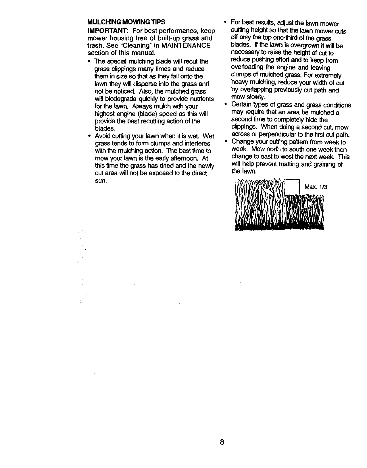
• For best results, adjustthe lawn mower
cutting height so that the lawn mower cuts
offonly the top one-third of the grass
blades. If the lawn is overgrown it will be
necessary to raise the height of cut to
reduce pushing effortand to keep from
overloading the engine and leaving
clumps of mulched grass. For extremely
heavy mulching,reduce your width of cut
by overlapping previouslycut path and
mowslowly.
• Certain types of grass and grass conditions
may requirethat an area be mulched a
second time to completely hide the
clippings. When doinga second cut, mow
across or perpendicular tothe first cut path.
• Change your cuttingpattern from weak to
week. Mow northto south one week then
change to east to west the next week. This
will help prevent matting and graining of
the lawn.
8
Page 9
v'
1- Changemoreoftenwhenoperatingundera heavyloadorinhighambienttemperatures.
2 °S_ moreoftenwhenopera_g k_dklyordustyoondltlons.
3 -ReptaceI_adesrno_eoftenwhenmowingInundy SOIL
4 -Charge48holmat endof _uon.
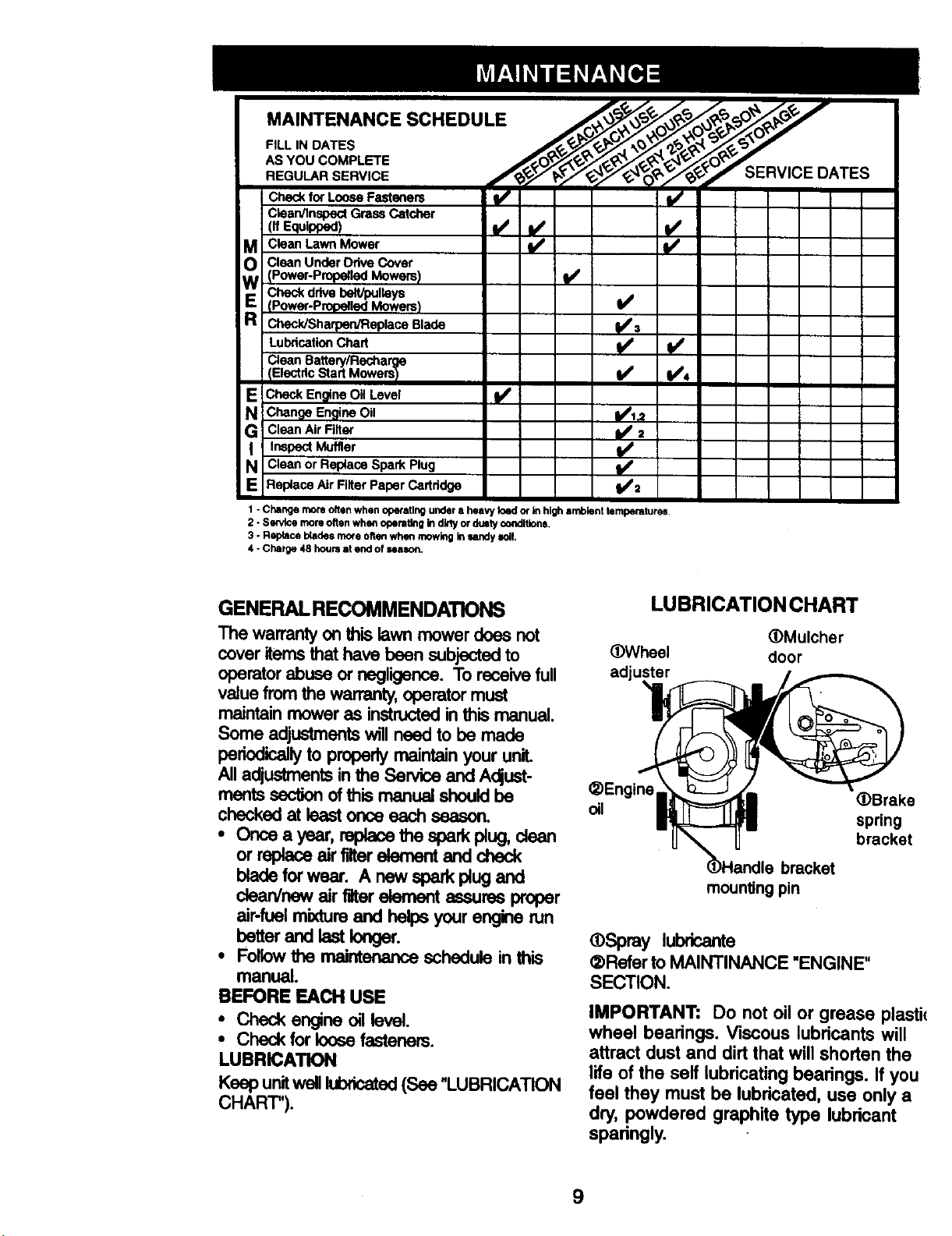
GENERAL RECOMMENDATIONS
The warranty on this lawn mower does not
cover items that have been subjected to
operator abuse or negligence. To receive full
value from the warranty, operator must
maintain mower as instructed inthis manual.
Some adjustments will need to be made
periodicallyto properly maintain your unit.
All adjustments in the Service and Adjust-
mentssection of this manual should be
chscked at least once each seascn.
• Once a year, replace the spark plug, clean
or replace air filterelement and check
blade forwear. A new spark plugand
dean/new air filter element assures proper
air-fuel mixture and helps your engine run
better and last longer.
• Followthe maintenance schedule in this
manual.
BEFORE EACH USE
• Check engine (xl level.
• Check for loose fasteners.
LUBRICATION
Keep unitwelllubricated(See "LUBRICATION
CHART").
LUBRICATION CHART
_Wheel
adjuster
_)Engine
oil
mounting pin
_)Spray lubricante
¢DReferto MAINTINANCE "ENGINE"
SECTION.
IMPORTANT: Do not oil or grease plastic
wheel bearings. Viscous lubricants will
attract dust and dirt that will shorten the
life of the self lubricating bearings. If you
feel they must be lubricated, use only a
dry, powdered graphite type lubricant
sparingly.
(DMulcher
door
_)Brake
spring
bracket
9
Page 10

PRODUCT SPECIFICATIONS
SERIALNUMBER
DATE OF PURCHASE
GASOLINE CAPACITY/TYPE:
:DILTYPE (API-SF/SG/SH):
OIL CAPACITY:
;PARK PLUG (GAP: .030" /
VALVE CLEARANCE:
SOLID STATE IGNITION
AIR GAP:
BLADE BOLT TORQUE: 35-40 FT. LBS.
The model and serial numbers will be found on a decal attached to the rear of the
lawn mower housing.Record both serial number and date of purchase in space
provided above.
1.5 QUARTS
UNLEADED REGULAR
SAE 30 (ABOVE 32°F)
SAE 5W-30 (BELOW 32°F)
2OOZS.
CHAMPION RJ19LM OR J19LM
INTAKE: .004 - .008
EXHAUST: .004 - .008
.0125 IN.
LAWN MOWER
Always observe safety rules when perform-
ing any maintenance.
TIRES
• Keep tires free of gasoline, oil, or insect
control chemicals which can harm rubber.
• Avoid stumps, stones, deep ruts,sharp
objects and other hazards that may cause
tire damage.
BLADECARE
For best results, mower blade must be
kept sharp. Replace bent or damaged
blades.
TO REMOVE BLADE
• Disconnect spark plug wire from spark
plug and place wire where it cannot
come in contact with spark plug.
• Turn lawn mower on its side. Make
sure air filter and carburetor are up.
• Use a wood block between blade and
mower housing to prevent blade from
turning when removing blade bolt.
° Protect your hands with gloves and/or
wrap blade with heavy cloth.
• Remove blade bolt by turning counter-
clockwise.
• Remove blade and attaching hardware
(bolt, lock washer and hardened
washer).
NOTE: Remove the blade adapter and
check the key inside hub of blade
adapter. The key must be in good
condition to work properly. Replace
adapter if damaged.
TO REPLACE BLADE
• Position the blade adapter on the
engine crankshaft. Be sure key in
adapter and crankshaft keyway are
aligned.
• Position blade on the blade adapter
aligning the two (2) holes in the blade
with the raised lugs on the adapter.
• Be sure the trailing edge of blade
(opposite sharp edge) is up toward the
engine.
• Install the blade bolt with the lock
washer and hardened washer into
blade adapter and crankshaft.
• Use block of wood between blade and
lawn mower housing and tighten the
blade bolt, turning clockwise.
• The recommended tightening torque is
35-40 ft. Ibs.
IMPORTANT: Blade bolt is grade 8 heat
treated.
10
Page 11

TO SHARPEN BLADE
NOTE: We do not recommend
sharpening blade - but if you do, be sure
the blade is balanced.
Care should be taken to keep the blade
balanced. An unbalanced blade will
cause eventual damage to lawn mower or
engine.
• The blade can be sharpened with a file
or on a grinding wheel. Do not attempt
to sharpen while on the mower.
• To check blade balance, drive a nail
into a beam or wall. Leave about one
inch of the straight nail exposed. Place
center hole of blade over the head of
the nail. If blade is balanced, it should
remain in a horizontal position. If either
end of the blade moves downward,
sharpen the heavy end until the blade
is balanced.
Blade
Key adapter Crankshaft
Blade
Lockwasher
Blade shaft
bolt Hardened Trailing
washer edge Blade adapter
keyway
• If lubricant is required, use only Texaco
Starplex Premium Grease, part no.
750369. Do not substitute.
DRIVE WHEELS
Check front drive wheels each time befon
you mow to be sure they move freely.
The wheels not turning freely means
trash, grass cuttings, etc. are in the drive
wheel area and must be cleaned to free
drive wheels.
If necessary to clean the drive wheels,
check both front wheels.
• Remove hubcaps, hairpin cotters and
washers.
• Remove wheels from wheel adjusters.
• Remove any trash or grass cuttings
from inside the dust cover, pinion and/
or drive wheel gear teeth.
• Put wheels back in place.
• If after cleaning, the drive wheels do no1
turn freely, contact your nearest
authorized service center.
ENGINE
LUBRICATION
Use only high qualitydetergent oil rated with
API service classificationSF, SG or SH. Selec
the oil's SAE viscositygrade according to you
expected operating temperature.
SAE VISCOSITY GRADES
GRASS CATCHER
(If purchased as an accessory)
• The grass catcher may be hosed with
water, but must be dry when used.
• Check your grass catcher often for
damage or deterioration. Through
normal use it will wear. If catcher
needs replacing, replace only with a
manufacturer approved replacement
catcher. Give the lawn mower model
number when ordering.
GEAR CASE
• To keep your drive system working
properly, the gear case and area
around the drive should be kept clean
and free of trash build-up. Clean under
the drive cover twice a season.
• The gear case is filled with lubricant to
the proper level at the factory. The only
time the lubricant needs attention is if
service has been performed on the
gear case.
-2O"
40" -20 = .10_ oP 10" 20" 30"
TEMPERATURE RANGE ANTICIPATED BEFORE NEXT O_L CHANGE
NOTE: Although multi-viscosity oils
(5W30, 10W30 etc.) improve starting in
cold weather, these multi-viscosity oils wil
result in increased oil consumption when
used above 32°F. Check your engine oil
level more frequently to avoid possible
engine damage from running low on oil.
Change the oil after every 25 hours of
operation orat least once a year ifthe lawn
mower is not used for 25 hours in one year.
Check the crankcase oil level before starting
the engine and after each five (5) hours of
continuous use. Tighten oil plug securely
each time you check the oil level.
11
Page 12

TO CHANGE ENGINE OIL
NOTE: Before tipping lawn mower to
drain oil, drain fuel tank by running
engine until fuel tank is empty.
• Disconnect spark plug wire from spark
plug and place wire where it cannot
come in contact with spark plug.
• Remove engine oil cap; lay aside on a
clean surface.
• Tip lawn mower on its side as shown
and drain oil into a suitable container.
Rock lawn mower back and forth to
remove any oil trapped inside of
engine.
• Wipe off any spilled oil on lawn mower
and on side of engine.
• Fill engine with oil. Fill only to the
"FULL" line on the dipstick. DO NOT
OVER FILL.
• Replace engine oil cap.
• Reconnect spark plug wire to spark
plug.
Turn
d.ock_s_
to
Slot
Air filter
clockwise to
Air filter cover tighten
MUFFLER
Inspect and replace corroded muffleras it
could create a fire hazard and/or damage.
SPARK PLUG
Change your spark plug each year to make
your engine start easier and run better. Set
spark plug gap at .030 inch.
CLEANING
IMPORTANT: For best performance, kiip
mower housing free of built-grass and
trash. Clean the underside of your mower
after each use.
Container
AIR FILTER
Your engine will not run properly and may
be damaged by using a dirty air filter.
Replace the air filter every year, more
often if you mow in very dusty, dirty
conditions. Do not wash air filter.
TO CHANGE AIR FILTER
• Remove the air filter by turning clock-
wise to the stop and pull away from
collar.
• Remove filter from inside of cover.
• Clean the inside of the cover and the
collar to remove any dirt accumulation.
• Insert new filter into cover.
• Put air filter cover and filter into collar
aligning the tab with the slot.
• Push in on cover and turn counterclock-
wise to tighten.
_CAUTION- Disconnect spark plug wire
from spark plug and place wire where it
cannot come in contact with the spark
plug.
• Turn lawn mower on itsside. Make sure air
filter and carburetor are up. Clean the
underside of your lawn mower by scr_ing
to remove build-up of grass and trash.
• Clean engine often to keep trash from
accumulating. A clogged engine runs
hotter and shortens engine life.
• Keep finishedsurfaces and wheels free of
all gasoline, oil,etc.
• We de not recommend using a garden
hose to clean lawn mower unless the
electrical system, muffler, air filter and
carburetor ere covered to keep water out.
Water in engine can result in shortened
engine life.
CLEAN UNDER DRIVE COVER
Clean under drive cover at least twice a
season. Scrape underside ofcover with putty
knife or similartoolto remove any build-upof
trash or grass on underside of drive cover.
12
Page 13

ACAUTION: Before performing any
service and adjustments:
• Release control bar and stop engine.
• Make sure the blade and all moving
parts have completely stopped.
• Disconnect spark plug wire from spark
plug and place where it cannot come
in contact with plug.
LAWN MOWER
TO ADJUST CUTTING HEIGHT
See "TO ADJUST CUTTING HEIGHT" in
the Operation section of this manual.
DISCHARGE GUARD
The discharge guard, attached to the
discharge opening of your lawn mower, is
provided to prevent the possibility of injury
resulting from objects being thrown out of
the discharge opening into the operator
mowing position. If the discharge guard
becomes damaged, it should be replaced.
REAR DEFLECTOR
The rear deflector, attached between the
rear wheels of your mower, is provided to
minimize the possibility that objects will
be thrown out of the rear of the mower into
the operator mowing position. If the
deflector becomes damaged, it should be
replaced.
TO REMOVE/REPLACE DRIVE BELT
TO ADJUST HANDLE
The handle can be mounted in a high or
low position. The mounting holes in the
bottom of lower handle are off center for
raising or lowering the handle.
• Remove upper handle and all parts
attached to lower handle.
• Remove hairpin cotters from lower
handle bracket mounting pin.
• Squeeze lower handle in to remove it
from mounting pins.
• Turn lower handle over to raise or
lower handle.
• Squeeze lower handle in and position
holes onto mounting pins on handle
bracket.
• Reassemble upper handle and all
parts removed from lower handle.
Mowing Mowing ,
position _.-'_ Position /_'
I i
Low position Highposition
pushing down on gear case pulley and
i Remove drive cover. Remove belt by
rolling belt off it.
Turn |awn mower on its side with
carburetor and fuel cap up.
• Remove blade.
• Remove debris shield.
• Remove belt from engine pulley on
crankshaft.
• Install new belt by reversing above
steps.
• Always use factory approved belt to
assure fit and long life.
Lower
handle
Rotate
13
Page 14

ENGINE
ENGINE SPEED
Your engine speed has been factory set.
Do not attempt to increase engine speed
or it may result in personal injury. If you
believe that engine is running too fast or
too slow, take your mower to an autho-
rized service center for repair and
adjustment.
CARBURETOR
Your carburetor has a non-adjustable
fixed main jet for mixture control. If your
engine does not operate properly due to
suspected carburetor problems, take your
lawn mower to an authorized service
center for repair and/or adjustment.
IMPORTANT: Never tamper with the
engine governor, which is factory set for
the proper engine speed. Overspeeding
the engine above the factory high speed
scan be dangerous. If you think the
engine-governed high speed needs
adjusting, contact your nearest
authorized service center, which has
proper equipment and experience to
make any necessary adjustments.
Immediately prepare your lawn mower for
storage at the end of the season or if the unit
willnot be used for 30 days or more.
LAWN MOWER
When lawn mower isto be stored for a period
of time, clean itthoroughly,remove all dirt,
grease, leaves, etc. Store in a clean, dry
area.
• Clean entire lawn mower (See "CLEAN-
ING" in the Maintenance section of this
manual).
• Lubricate as shown in the Maintenance
section of this manual.
• Be sure that all nuts, bolts, screws, and
pins are securely fastened. Inspect
moving parts for damage, breakage and
wear. Replace ifnecessary.
• Touch up all rusted or chipped paint
surfaces; sand lightlybefore painting.
HANDLE
You can fold your lawn mower handle for
storage.
• Squeeze the bottom ends of the lower
handle toward each other until the lower
handle clears the handle bracket, then
move handle forward.
• Loosen upper handle mounting bolts
enough to allow upper handle to be folded
back.
IMPORTANT: When folding the handle
for storage or transportation, be sure to
fold the handle as shown or you may
damage the control cables.
• When setting up your handle from the
storage position,the lower handle will
automatically lock into the mowing
position.
Lower handle
Squeeze to
_ld
/,
Hairpin pin
cotter
Operator presence control
bar
Upper handle
Fold forward for _,,
storage
_7/_'_ _,_ Fold
___'//" l backward
_ Mowing
"'._J" position
14
Lowe
handle
Page 15

ENGINE
FUELSYSTEM
IMPORTANT: It is important to prevent
gum deposits from forming in essential
fuel system parts such as carburetor, fuel
filter, fuel hose, or tank during storage.
Also, experience indicates that alcohol
blended fuels (called gasohol or using
ethanol or methanol) can attract moisture
which leads to separation and formation
of acids during storage. Acidic gas can
damage the fuel system of an engine
while in storage.
• Drain the fuel tank
• Start the engine and let it run until the fuel
lines and carburetor are empty.
• Never use engine or carburetor cleaner
products inthe fuel tank or permanent
damage may occur.
• Use fresh fuel next season.
NOTE; Fuel stabilizer is an acceptable
alternative in minimizing the formation of
fuel gum deposits during storage. Add
stabilizer to gasoline in fuel tank or
storage container. Always follow the mix
ratio found on stabilizer container. Run
engine at least 10 minutes after adding
stabilizer to allow the stabilizer to reach
the carburetor. Do not drain the gas tank
and carburetor if using fuel stabilizer.
ENGINEOIL
Drain oil (with engine warm) and replace with
clean engine oil (See "ENGINE" in the
Maintenance section of this manual).
CYLINDER
• Remove spark plug.
• Pour one ounce (29 ml) of oil through
spark plug hole into cylinder.
• Pull starter handle slowly a few times to
distribute oil.
• Replace with new spark plug.
OTHER
• Do not store gasoline from one season to
another.
• Replace your gasoline can ifyour can
startsto rust. Rustand/or dirtinyour
gasoline will cause problems.
• Ifpossible, store your unitindoors and
cover if to give protectionfrom dust and dirt.
• Cover your unitwith a suitable protective
cover that does not retain moisture. Do not
use plastic. Plasticcannot breathe which
allows condensation to form and will cause
your unit to rust.
IMPORTANT: Never cover mower while
engine and exhaust areas are still warm.
ACAUTION: Never store the lawn
mower with gasoline in the tank inside a
building where fumes may reach an open
flame or spark. Allow the engine to cool
before storing in any enclosure.
15
Page 16

TROUBLESHOOTING CHART
)ROBLEM CAUSE CORRECTION
Does not start
Loss of power
Poor cut- uneven
1. Dirty airfilter.
2. Out of fuel.
3. Stale fuel.
4. Water in fuel.
5. Spark plug wire is
disconnected.
6. Bad spark plug.
7. Loose blade or broken blade
adapter.
8. Control bar in released
position.
9. Control bar defective.
1. Rear of lawn mower housing
or cuttingblade dragging
in heavy grass.
2. Cuttingtoo much, grass.
3. Dirtyair filter.
4. Buildup of grass, leaves,
and trash under mower.
5. Too much oil in engine.
6. Walking speed too fast.
1. Worn, bent or loose blade.
2. Wheal heights uneven.
3. Buildup of grass, leaves
and trash under mower.
1. ClearVreplace air filter.
2. Fill fuel tank.
3. Drain tank and refillwith
fresh clean fuel.
4. Drain fuel tank and
carburetor and refilltank
with fresh gasoline.
5. Connect wire to plug.
6. Replace spark plug.
7. Tighten blade bolt or
replace blade adapter.
8. Depress controlbar to
handle.
9. Replace control bar.
1. Set to "Higher Cut"
pos_on.
2. Set to "Higher Cur
position.
3. Clean/replace air filter.
4. Clean underside of mower
housing.
5. Check oil level.
6. Cut at slower walking
speed.
I
I1. Replace blade. Tighten
blade bolt.
2. Set all wheels at sarne
height
3. Clean underside of
mower housing.
16
Page 17

TROUBLESHOOTING CHART
PROBLEM CAUSE CORRECTION
Excessive
vibration
Starter rope herd
topull
Loss of ddve
Grass catcher
not filling (if so
equipped)
1. Wom, bent or loose blade.
2. Bent engine crankshaft.
.
Engine flywheel brake is on
when control bar is released.
.
Bent engine crankshaft.
3.
Blade adapter broken.
4.
Blade dragging in grass.
1. Drive wheels not turning
with drive control engaged.
2. Belt not driving
1. Cutting heighttoo low.
2. Lifton blade worn off.
3. Catcher not venting air.
1. Re_ace blade. TKjhten
blade bolt.
2. Contact an authorized
service center.
1. Depress control bar to
upper handle before
pullingstarter rope.
2. Contact an authorized
service center.
3. Replace blade adapter.
4. Move lawn mower to cut
grass or to hard surface.
1. Adjust or replace drive control
cable.
2. Put belt on pulleys or
replace belts if broken.
1. Raise cutting height.
2. Replace blade.
13. Clean grass catcher.
Hard to push
1. Grass is too high or wheel
he'_ht is too low.
2. Rear of lawn mower
housing or blade dragging
in grass.
3. Grass catcher too full.
4. Handle height position not
rightforyou.
1. Raise cutting height.
2. Raise rear of lawn mower
housing one (1) setting
higher.
3. Empty grass catcher.
4. Adjust handle height to
suit.
17
Page 18

SERVICENOTES
34
Page 19

ROTARY LAWN MOWER -- MODEL NO. 917.377425
GEAR CASE ASSEMBLY PART NUMBER 702511
15
14
KEY PART
NO. NO. DESCRIPTION
1 17490416 Tapping Screw 1/4-20 x 1÷1/4
2 137055X0(H EngagementBracket
3 137053 Shifter
4 57072 Seal
6 48373 Gear Case Halves Kit (Includes Key Nos. 4, 6, and 7)
7 77881 Beadng
8 137051 Worm Shaft
9 137074 Drive Shaft
10 57079 Hardened Washer
11 131484 Clutch Yoke
12 700343 Bushing
13 86447 Plug
14 137050 Helical Gear
15 750436X Clutch Jaw
16 750369 Grease
17 12000O03 E-Ring
18 850848 Hi-Pro Key
19 81585X004 Spring Bracket
NOTE: All component dimensions given
in U.S. inches. 1 inch = 25.4 mm
35
Page 20

ROTARY LAWN MOWER - MODEL NO. 917.377425
68
3g
10 16
40
35
48
18 33
25
62
35
4O
48
2
42
72
52
Page 21

ROTARY LAWN MOWER -MODEL NO. 917.377425
KEY
NO.
1
2
3
5
7
8
9
10
11
12
16
17
18
19
22
23
24
25
27
28
29
3O
31
32
33
35
36
38
39
4O
41
42
43
44
45
46
PART
NO,
165452X479
STD541425
168,5,52
153638
131959
66426
51793
136376
88348
157081X479
STD512505
165175X479
170346X479
170345X479
14O540
750097
87584X004
151889
147286
154132
152124
751592
700168X479
700166X479
74760612
750085X007
146630
700331X004
701037
750913X004
61651
142748
151138
57143
83923
85463
DESCRIPqX)N
UpperHandla
Lock.nut
ZoneControlCalVe
RopeGulde
HandleBolt
Wire'rk_
HairplnCotter
HandleKnot}
FlatWasher3/8
LowerHandle
HexTappingScrew1/4-20 x 1/2
SupportRod
HandleBracketAssenlbly(Left)
HandleBracketAssembly(Right)
RearDeflector
HexWasher Head Screw #10.24 x 1/2
DeflectorBracket
DischargeGUard
HingeRod
HousingBracket
TorsionSpring
Locknut
SupportBraCket(Left)
SupportBraCket(Right)
HexHead Bolt3/8-16x3/4
WheelAdjuStingBracket
spacer
SelectorSpring
SelactorKnob
AxleArmAssembly
BellevllleWasher
ShoulderBOlt
Wheel& TireAssembly
WaveWasher
Locknut3/18-16
DangerDecal
KEY PART
NO. NO. DESCRIPTION
48 149741 Thread Cutting Screw 5/16-18 x 3/4
49 STD541425 Hex Locknut
51 134612 Debris Shield
52 150406 Hex Head Thread Rolling Screw 3/8-16 x 1-
1/6
53 851084 Hex Head Screw 3/8-24 x 1-3/8 (Grd. 8)
54 850263 Helical Lockwasher
55 851074 Hardened Washer
56 152202 Blade22"
57 851514 Blade Adapter
58 752118 Deflector
59 751399 Bracket, Deflector
60 74180410 screw 1/4-20
62 171037 Lawn Mower Housing (Incl. Ref. #46)
63 85548 Engine Pulley
64 87677 Hi-Pro Key #HP 505
68 ...... Engine - (See Breakdown) Craftsman
Model 143.006502
69 153350X479 Support Brkt Handle RH
70 153282X479 Support Brkt Handle LH
71 63601 Locknut Keps
72 151440 Hubcap
- - 161058 Warning Decal (Not Shown)
- - 172521 Owner's Manual (EnglisWSpanish)
Availableaccessoriesnotincludedwithlawnmower:
71 33072 Grass Catcher
71 33623 Gas Can (2.5 gal.)
71 33500 Fuel Stabilizer
71 33300 SAE 3OW Oil (20 oz.)
71 33316 Mower Cover
Page 22

ROTARY LAWN MOWER - MODEL NO. 917.377425
28
30
24
_.-36
18
22
23
Page 23

ROTARY LAWN MOWER- MODEL NO. 917.377425
KEY
NO.
1
2
4
5
6
9
12
15
18
19
21
22
PART
NO.
145793
STD54!425
158755
145755
146527
150495
751152
701037
88118
67725
88O8O
137054
DESCRIPTION
Control Bar
Locknut 1/4-20
HexWasher Head Screw
ControlCableAssembly
V-Belt
SpringRetainer
Locknut1/4-20
SelectorKnob
FeltWasher
Washer 1/2x 1-1/2 x .134
DustCover
Pinion
1/4 x 2.0
KEY PART
NO. NO. DESCRIUq'ION
23 12000058
24 150340
26 145212
28 150182
30 143603
32 154990
36 132010
37 137052
39 75192
41 137090
42 702511
43 152018
44 152019
45 86012
E-Ring
Wheel &Tire Assembly
Hex Flange Locknut
Hubcap
Pan Head Tapping Screw #10-24 x 2-3/4
DriveCover
Locknut
Drive Pulley
Spnng
Spdng
Gear Case Assembly
Wheel Adjuster Assembly (Left)
Wheel Adjuster Assembly (Right)
Ddvsshaft Cover
Page 24

CRAFTSMAN 4-CYCLE ENGINE MODEL NUMBER 143.006502
_7
263A
260
1821_
178
120
239 /)
119
125
,.313
.-20
5 1310
46
238 250
4O
Page 25

CRAFTSMAN 4-CYCLE ENGINE MODEL NUMBER 143.006502
K]EY PART
NO. NO. DESCRIPTION
1 37266
2 26727
6 33734
7 36557
12 36775
12A 36558
12B 36694
14 28277
15 30589
16 34839A
17 31335
18 651018
19 36281
20 32600
3O 37464
40 40027
40028
Cylinder (Incl. 2,20 & 150) 174 30200
Dowel Pin 178 29752
Breather Element 182 6201
Breather Ass'y. (Incl. 6 & 184 26756
12A)
BreatherTube 185 36785
Breather Cover & Tube (Incl. 186 326.53
12B) 189 650839
BreatherTube Elbow 191 36559A
Washer
Governor Rod (Incl. 14) 195 610973
Governor Lever 207 34336
Governor Lever Clamp 216 33086
Screw, Torx T-15, 8-32 x 19/ 223 650451
64" 224 36786
Extension Spring 238 650932
Oil Seat 239 34338
Crankshaft 241 36919
Piston, Pin & Ring Set (Std.) 245 36905
Piston, Pin & Ring Set (.010" 250 36920
os) 26O 3698O
41 40026
40026
42 40006
40007
43 20381
45 36777
46 32610A
48 27241
50 37460
52 29914
69 35261
70 34311E
72 30572
73 28833
75 27897
80 30574A
81 30590A
82 30591
83 30588A
86 650488
89 611004
90 611112
92 650815
93 650816
100 34443B
101 610118
103 651007
110 37047
119 36787
120 36825
125 37288
126 37289
130 6021A
135 35395
150 31672
151 31673
151A 40017
169 36783
172 36784
Piston & Pin Ass'y. (Std.) 261 30200
(Incl. 43) 262 650831
Piston & Pin Ass'y.(.010" OS 263A 37184
(Incl. 43) 275 36790A
Ring Set (Std.) 277 650988
Ring Set (.010" OS) 285 35000A
Piston Pin Retaining Ring 287 650926
Connecting Rod Ass'y. (Incl. 290 29774
46) 292 26460
Connecting Rod Bolt 298 28763
Valve Lifter 300 36916
Camshaft (MCR) 301 36246
Oil Pump Ass'y. 305 35647
• Mounting Flange Gasket 306 36996
Mounting Flange (Incl. 72 thru 307 35499
83,306) 309 650562
Oil Drain Plug (Incl. 73) 310 35648
Drain Plug Gasket 313 34080
Oil Seal 325 37152
Governor Shaft 347 651038
Washer 355 590701
Governor Gear Ass'y. (Incl. 370A 36261
81) 370C 37318
Governor SPOol 370R 37317
Screw, 114-20 x 1-1/4" 380 640262
Flywheel Key 390 690739
• Flywheel 400 36792B
Belleville Washer
Flywheel Nut 416 36085
Solid State Ignition
Spark Plug Cover 417 650821
Screw, Torx T-15, 10-24 x 15/
16" 900
GroundWire 900
* Cylinder Head Gasket
Cylinder Head
Exhaust Valve (Std.) (Incl.
151)
Intake Valve (Std.) (Incl. 161)
Screw, 5/16-18 x 1-1/2"
Resistor Spark Plug
(RJ19LM)
Valve Spring
Valve Spring Cap
Intake Valve Seal
• Valve Cover Gasket
Valve Cover
KEY PART
NO. NO. DESCRIPlqON
Screw, 10-24 x 9/16"
Nut & Lock Washer, 1/4-28
Screw, 1/4-28 x 7/8'
* Carburetor To Intake Pipe
Gasket
Intake Pipe
Governor Link
Screw, 114-20 x 3/8"
S.E. Brake Bracket (Incl.
195)
Terminal
Throttle Link
R.P.M. Adjusting Lever
Screw, 1/4-20 x 1"
* Intake Pipe Gasket
Screw, 10-32 x 49164"
* Air Cleaner Gasket
AirCleanerCollar
Air Cleaner Filtar
Air CleanerCover
BlowerHousing
Screw, 10-24 x 9/16"
Screw, 1/4-20 x 1/2"
Starter Grill
Muffler
Screw, 1/4-20 x 2-5/16"
StarterCup
Screw, 8-32 x 21/64"
FuelLine
FuelLine Clamp
Screw, 10-32 x 35/64"
Fuel Tank (Incl. 292 & 301)
FuelCap
Oil FillTube
• "O"-Ring
"O"-Ring
Screw, 10-32 x 1/2"
Dipstick
Spacer
SpringClip
Screw, 10-32 x 51/64"
Starter Handle
Lubrication Decal
Primer Decal (3 X)
Warning Decal
Carburetor (Incl. 184)
Rewind Starter
Gasket Set (Incl. Items
Marked*)
Spark Arrestor Kit (Incl.
417)(Optional)
Screw, 10-32 x 1/2=
(Optional)
Replacement Engine NONE
Replacement S/B 750859,
orderfrom 71-999
RPM High 2900 to 3200
NOTE: This engine could have been built with 590702
starter).
NOTE= Alt component dimensions given in U.S. inches
1 inch = 25.4 mm
41
Page 26

CRAFTSMAN 4-CYCLE ENGINE MODEL NUMBER 143.006502
I
NO.
2O
20A
1
2
4
5
6
7
16
17
18
25
27
28
29
3O
31
35
36
36A
37
4O
44
47
48
6O
PARr
NO.
64O262
_1615
_1_7
_1184
_11_
64O070
6505O6
6O16O7
_1_5
6307_
640018
64O2OO
_1_7
_1024
632019
_1028
_1021
6O10_
64O2_
64OO80
6327_
632547
640175
_110A
63O7_
_I_7
63276OB
DESCRIPTION
Carburetor(Incl. 184 of EnginePartsList)
ThrottleShaft & LeverAssembly
ThrottleRetumSpring
* DustSeal Washer
* DustSeal (Throttle)
ThrottleShutter
* ShutterScrew
FuelFitting
ThrottleCrackScrew/IdleSpeedScrew
TensionSpdng
IdleRestdctorScrew
IdleRestdctorScrwe Cap (Black)
FloatBowl
* Float Shaft
Float
* FloatBowl"O"Ring
* Inlet Needle,Seat, & Clip(IncL31)
SprlngClip
PdmerBultYRetalnerRing
MainNozzleTube
CarburetorTube
* "O"Ring,MainNozzleTube
HighSpeedBowlNut
BOWlNutWasher
Welchplugi;IdleMixture Well
WelchPltJgAtmosphericVent
Repairi_t_lnc, ItemsMarked*)
42
Page 27

CRAFTSMAN 4-CYCLE ENGINE MODEL NUMBER 143.006502
i tl
KEY
NO.
1
2
3
4
5
6
7
8
PARr
NO.
590702
590599A
5906OO
590696
5906O1
59O697
59O698
590699
590700
DESCRIPTION
RecoilStarter
SpringPin (Incl.4)
Washer
Retainer
Washer
BrakeSpring
StarterDOg
DogSpring
Pulley&RewindSpring
Ass'y.
11
590703
StarterHousingAss'y.(40
degreegrommet)
12
590535
StarterRope( 98"X 9/64"
dia.)
13
590701
--S
StarterHandle
V--t4
!1 III -T
KEY
NO.
m__
11
12
13
14
3
6
7
8
PARr
NO.
590739
590740
590616
590617
590618A
59O638
59O535
590701
590760
DESCRIPTION
RewindStarter
Retainer
StarterDog
DogSpdog
Pulley& RewindSpringAss'y
StarterHousingAss'y(40
degreegrommet)
StarterRope(Length98" x
9164"alia.)
StarterHandle
SpdngClip
43
Page 28

For repair of major brand appliances in your own home...
no matter who made it, no matter who sold it!
1-800-4-MY-HOME S_Anytime,dayor night
(1-800-4694663)
www.sears.com
To bring in products such as vacuums,
lawn equipment and electronics for repair, call for
the location of your nearest Sears Parts & Repair Center.
1-800-488-1222 Anytirnadayor night
www.sears.com
For the replacement parts, accessories and owner's manuals
that you need to do-it-yourself,call Sears PartsDirectSa!
1-800-366-PART 6ar.- 11p.m.CST,
(1-800-366-7278) 7 daysa week
www.sears.com/partsdirect
To purchase or inquire about a Sears Service Agreement:
1-800-827-6655
7 a.m. - 5 p.m. CST, Mon.- Sat.
Para pedir servicio de reparacibn a domicilio, Au Canada pour service en fran_ais:
y para ordenar piezas con entrega a domicilio: 1-877-LE-FOYER _
1-888-SU-HOGAR s.
(1"888-784"6427)
© Seem, Roebuck and Co,
® RegisteredTrademark/ Trademark of Sears,Roebuckand Co,
® Marca Registrada / TMMarca de Fdbdca de Seam, Roebuck and Co.
YM
(t -877-533-6937)
172521 1.24.00 TR Printed in U.S.A.
 Loading...