

Page 1
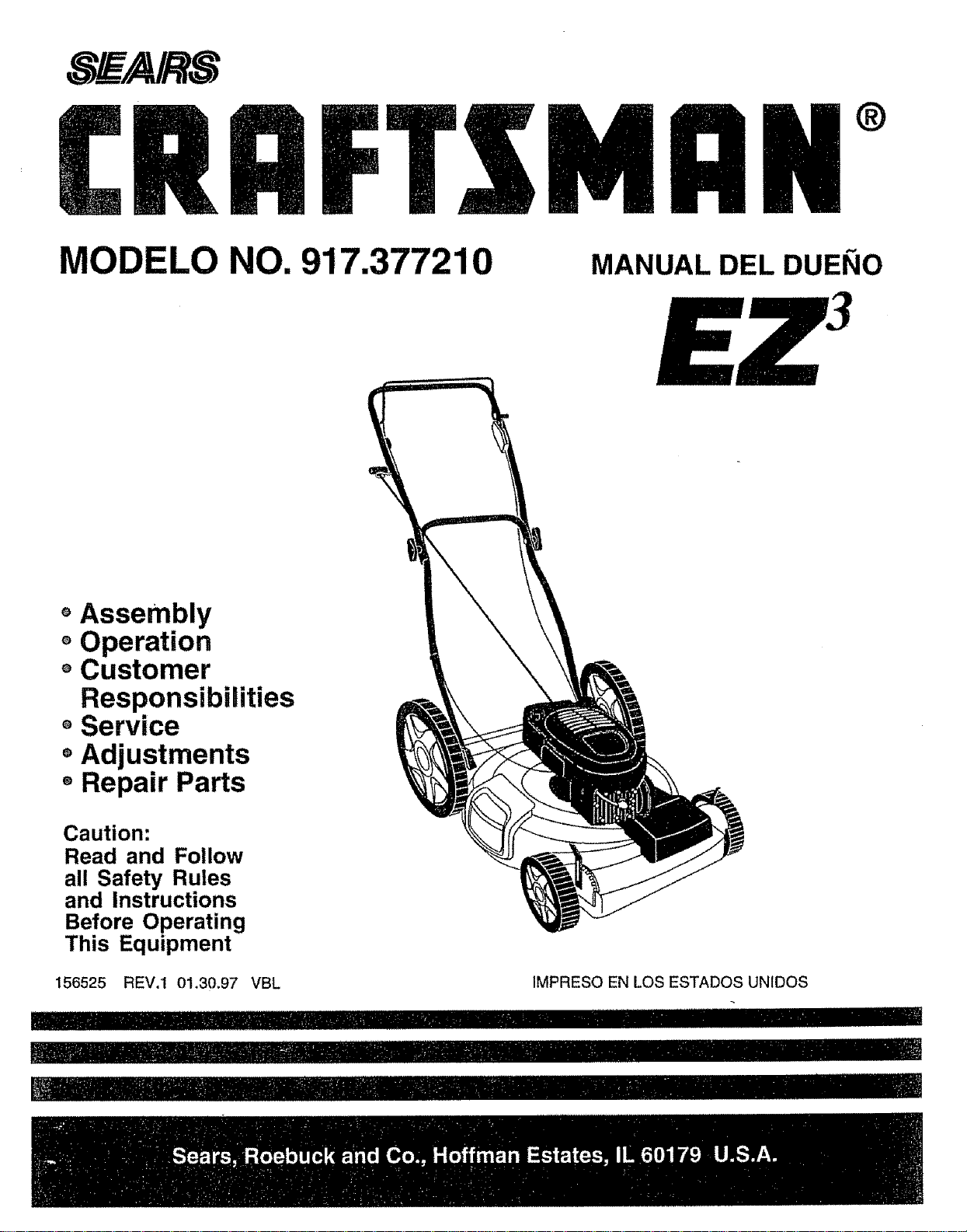
CRRFTSMnN°
MODELO NO. 917.377210
oAssembly
oOperation
oCustomer
ResponsibiDities
oService
MANUAL DEL DUEI_IO
• Adjustments
Repair Parts
Caution:
Read and Follow
all Safety Rules
and Instructions
Before Operating
This Equipment
156525 REV.1 01.30.97 VBL IMPRESO EN LOS ESTADOS UNIDOS
IIII II.........................'H'll"l'l!ll'' IIIIIII IIIIIIrll t,ii
_,-,-, _ I IIIII'llIIIll_r _r,_,_,_,_llllllllrl_
I' I I li
Page 2
SAFETY RULES zt
Safe Operation Practices for Walk-Behind Mowers
IMPORTANT: THIS CUTTING MACHINE 1SCAPABLE OF AMPUTATING HANDS AND FEET AND THROWING OBJECTS°
FAILURE TO OBSERVE THE FOLLOWING SAFETY INSTRUCTIONS COULD RESULT IN SERIOUS INJURY OR DEATH
SAFETY STANDARDS REQUIRE OPERATOR PRESENCE CONTROLS TO MINIMIZE THE RISK OF INJURY. YOUR UNIT IS
EQUIPPED WITH SUCH CONTROLS. DO NOT ATTEMPT TO DEFEAT THE FUNCTION OF THE OPERATOR PRESENCE
CONTROLS UNDER ANY CIRCUMSTANCES
TRAINING:
• Read this operator's manual carefully. Become familiar with
the controls and know how to operate your mower properly
Learn how to quickly stop mower.
• Do not allow children to use your mower. Never allow adults
to use mower without proper instructions
• Keep the area of operation clear of all persons, especially
small children and pets
° Use mower only as the manufacturer intended and as de*
scribed in this manual
• Do not operate mower if it has been dropped or damaged in
any manner Always have damage repaired before using
your mower
• Do not use accessory attachm ents that are not recommended
by the manufacturer Use of such attachments may be
hazardous
• The blade turnswhen theengine is running
PREPARATION:
• Always thoroughly check the area to be mowed and clear it of
ali stones, sticks, wires, bones, and other foreign objects
These objects wil! be thrown by the blade and can cause
severe injury
- Always wear safety glasses or eye shields when starting and
while using your mower
• Dress properly Do not operate mower when barefoot or
wearing open sandals Wear only solid shoes with good
traction when mowing
• Check fuel tank before starting engine Do not fill gas tank
indoors, when the engine isrunning or when the engine is hoL
Allow the engine to coot for several minutes before filling the
gas tank Clean off any spilled gasoline before starting the
eng]ne_
• Always make wheel height adjustments before starting your
mower Never attempt to do this whi_ethe engine is running
• Mow only in daylight or good artificial light
OPERATION:
• Keep your eyes and mind on your mower and the area being
cut Do not let other interests distract you
• Do not mow wet or slippery grass Never run while operating
your mower Always be sure el your footing - keep a firm hold
on the handles and walk
• Do not put hands or feet near or under rotating parts Keep
clear of the discharge opening at all times
• Always stop the engine whenever you leave or are not using
your mower, or before crossing driveways, walks, roads, and
any gravel-covered areas
• Never direct discharge of material toward bystanders nor
allow anyone near the mower while you are operating it
• Before cleaning, inspecting, or repairing your mower, stop the
engine and make absolutely sure the blade and all moving
parts have stopped Then disconnect the spark plugwire and
keep it away from the spark plug to prevent accidental
starting
• Do not continue to run your mower if you hit a foreign object.
Follow the procedure outlined above, then repair any dam-
age before restarting and operating you mower
• Do not change the governor settings or overspeed the
engine Engine damage or personal injury may result°
• Do not operate your mower if it vibrates abnormally° Exces-
sive vibration is an indication of damage; stop the engine,
safely check for the cause of vibration and repair as required
• Do not run the engine indoors. Exhaust fumes are danger-
ous
• Never cut grass by pulling the mower towards you Mew
across the face of slopes, never up and clownor you might
lose your footing Do not mow excessively steep slopes Use
caution when operating the mower on uneven terrain or when
changing directions - maintain good footing
• Never operate your mower without proper guards, plates,
grass catcher or other safety devices in place
MAINTENANCE AND STORAGE:
° Check the blade and the engine mounting bolts often to be
sure they are tightened properly_
• Check all bolts, nuts and screws at frequent intervals for
proper tightness to be sure mower is in safe working condi-
tion
• Keep all safety devices in ptace and working
• To reduce fire hazard, keep the engine free of grass, leaves
or excessive grease and oil
• Check grass catcher often for deterioration and wear and
repface worn bags Use only replacement bags that are
recommended by and comply with specifications of the
manufacturer of your mower.
• Always keep a sharp bJade on your mower
• Allow engine to coot before storing in any enclosure
• Never store mower with fuel in the tank inside a building
where fumes may reach an open flame or an ignition source
such as a hot water heater, space heater, clothes dryer, etc
, ,, ,,,,,,,,,,,,,, , , ...............................
Look for this symbol to point out iT' !
CAUTIONIil BECOMEALERTt!! YOUR
portant safety precautions. It means
SAFETY IS INVOLVED.
i ,i i ii i
III ii iii iiii ii ii ii i ii iiii i i ii i iii
CAUTION: Always disconnect spark I
not contact spark plug in order to pre- I
plug wire and place wire where it can- I
vent accidental starting when setting |
up, transporting, adjusting or making |J
HiH Hi HiH I 11 I = = = II
repairs.
I1 I1111111II I =H,I HImH
A WARNING A
The engine exhaust from this product con-
tains cl_emicals known to the State of Califor-
nia to cause cancer, birth defects, or other
reproductive harm,
==== =
!
Page 3
CONGRATULATIONS on your purchase of a Sears Lawn
Mower. It has been designed, engineered and manufac-
tured to give you the best possible dependability and
performance..
Should you experience any problem you cannot easily
remedy, please contact your nearest Sears Authorized
Service Center/Department. We have competent, wed
trained technicians and the proper tools to service or repair
this lawn mower.
Please read and retain this manual. The instructions will
enable you to assemble and maintain your lawn mower
properly. Always observe the "SAFETY RULES".
MODEL
NUMBER 917.377210
SERIAL
NUMBER
DATE OF PURCHASE
THE MODEL AND SERIAL NUMBERS WILL BE FOUND
ON A DECAL ATTACHED TO THE REAR OF THE
LAWN MOWER HOUSING
YOU SHOULD RECORD BOTH SERIAL NUMBER AND
DATE OF PURCHASE AND KEEP IN A SAFE PLACE
FOR FUTURE REFERENCE.
PRODUCT SPECIFICATIONS
HORSEPOWER: 6.25
DISPLACEMENT: t2.56 CU. IN_
GASOLINE CAPACITY 1.6 QUARTS
AND TYPE: UNLEADED REGULAR
OIL TYPE (API-SF/SG): SAE 30 (ABOVE 32°F)
SAE 5W_30 (BELOW 32'_F)
OIL CAPACITY: 20 OZS
SPARK PLUG: CHAMPION Jt9LM, RJ19LM
GAP: 030") STD361458
VALVE CLEARANCE: INTAKE: .005*.007
EXHAUST: ,007-.009
SOLID STATE IGNITION
AIR GAP: ,0125 IN
BLADE BOLT TORQUE: 35_40 FT LBS
MAINTENANCE AGREEMENT
A Sears Maintenance Agreement is available on this product. Contact your nearest Sears store for details.
CUSTOMER RESPONSIBILITIES
• Read and observe the safety rules_
, Follow a regular schedule in maintaining, caring for and using your lawn mower.
, Follow the instructions under "Customer Responsibilities" and "Storage" sections of this owner's manual.
, uuul i, i, n i ilul ,, ii ,llluuul i nur, l,,r,,, i,,11, iii
MMITED'TWO YEAR WARRANTY ON CRAFTSMAN POWER MOWER
For two (2) years from date of purchase, when this Craftsman Lawn Mower is maintained, lubricated, and tuned up
according to the operating and maintenance instructions in the owner's manual, Sears will repair free of charge any
defect in material or workmanship.
If this Craftsman Lawn Mower is used for commercial or rental purposes, this warranty applies for only 90 days from
the date of purchase.
This Warranty does not cover:
• Expendable items which become worn during normal use, such as rotary mower blades, blade adapters, belts,
air cleaners and spark plug.
• Repairs necessary because ofoperator abuse or negligence, including bent crankshafts and the failure to maintain
the equipment according to the instructions contained in the owner's manual
WARRANTY SERVICE IS AVAILABLE BY RETURNING THE CRAFTSMAN POWER MOWER TO THE NEAREST
SEARS SERVICE CENTER/DEPARTMENT IN THE UNITED STATES. THIS WARRANTY APPLIES ONLY WHILE
THIS PRODUCT IS IN USE IN THE UNITED STATES..
This Warranty gives you specific legal rights, and you may also have other rights which vary from state to state,.
SEARS, ROEBUCK AND CO, D/817 WA, HOFFMAN ESTATES, ILLINOIS 60179
Page 4
i ill, i, u i L i ,lllll,,,,, Jil, i ill ill ill, ii ,ll,i J, i i,i J" ,,,,rl,.......................
TABLE OF CONTENTS
Hlllll ii, ,,,,,, ,l,l_Jl_ Hi liN IllUL'.................................. 'l"Hll q _l[Jm',,l' ' m '
SAFETY RULES ............................................................ 2
PRODUCT SPECIFICATIONS ...................................... 3
CUSTOMER RESPONSIBILITIES ....................... 3, 9-11
WARRANTY .................................................................. 3
ASSEMBLY .................................................................... 5
OPERATION .................................................................. 6
MAINTENANCE SCHEDULE ........................................ 9
Engine:
Air Filter ...................................... 11
Oil Change .............................. 11
Oil Level ................................... 11
Oil Type ........................................11
Starling ....................................... 8
Stopping .......................................8
Storage .................................... 14
Fuel:
Capacity .................................. 3
B
Blade:
Sharpening ........................... 10
Replacement ......................... 10
C
Controls:
Drive Control ................................6
Engine Zone Control .................. 6
Engine Speed Control .............. 6
Operator Presence
Control Bar ............:......................6
Customer Responsibilities ...... 3, 9-1 'I
Air Filter .................................. 11
Blade CarelReplacement ...... 10
Drive Wheels .............................10
Engine ....................................... 11
Lubrication .................................. 9
Spark Plug ................................ 11
CUtting Levels ......................................7
Storage ..........................................14
Type .............................................. 8
Handle Adjustment:
Assembly ................................... 5
Cutting Height ........................... 13
Lubrication:
Engine ....................................... 11
Lawn Mower .............................. 9
Maintenance Agreement ............... 3
Maintenance Schedule ........................9
Mowing Tips ................................... 8
Oil:
Engine ....................................... 11
Storage ................................. 14
SERVICE AND ADJUSTMENTS ................................. 12
STORAGE .................................................................... 14
REPAIR PARTS - LAWN MOWER ........................ 15-19
REPAIR PARTS - ENGINE ..................................... 20-22
TROUBLESHOOTING ................................................. 23
PARTS ORDERING/SERVICE .................................... 26
E
F
H
L
M
O
Operation:
Drive Control .................................7
Engine Control .............................7
Grass Catcher .................................7
Mower ............................................7
Operator Presence
Control Bar .................................. 7
Options:
Accessories ...................................5
R
Repair Pads:
Engine ....................................20-22
Lawn Mower .........................15-t9
Responsibilities, Customer 3, 9-11
Safety Rules .........................................2
Service and Adjustments .............. 12
Carburetor ......................................13
Drive Belt ................................. 12
Engine Speed ............................13
Handle ........................................ 13
Spark Plug ........................................ 1t
Specifications .................................. 3
Speed Control:
Engine ....................................... 7
Starting the Engine ..............................8
Stopping the Engine ............................8
Storage ........................................... 14
Trouble Shooting Cha_ ................. 23
W
Warranty ........................................... 3
4
Page 5
....... i, , i ...... i ,11 ,,,U,l,l,,,, ,i i ¸
] u ,,Ul ,i nl,,, iiii m i, ,lull, i I'
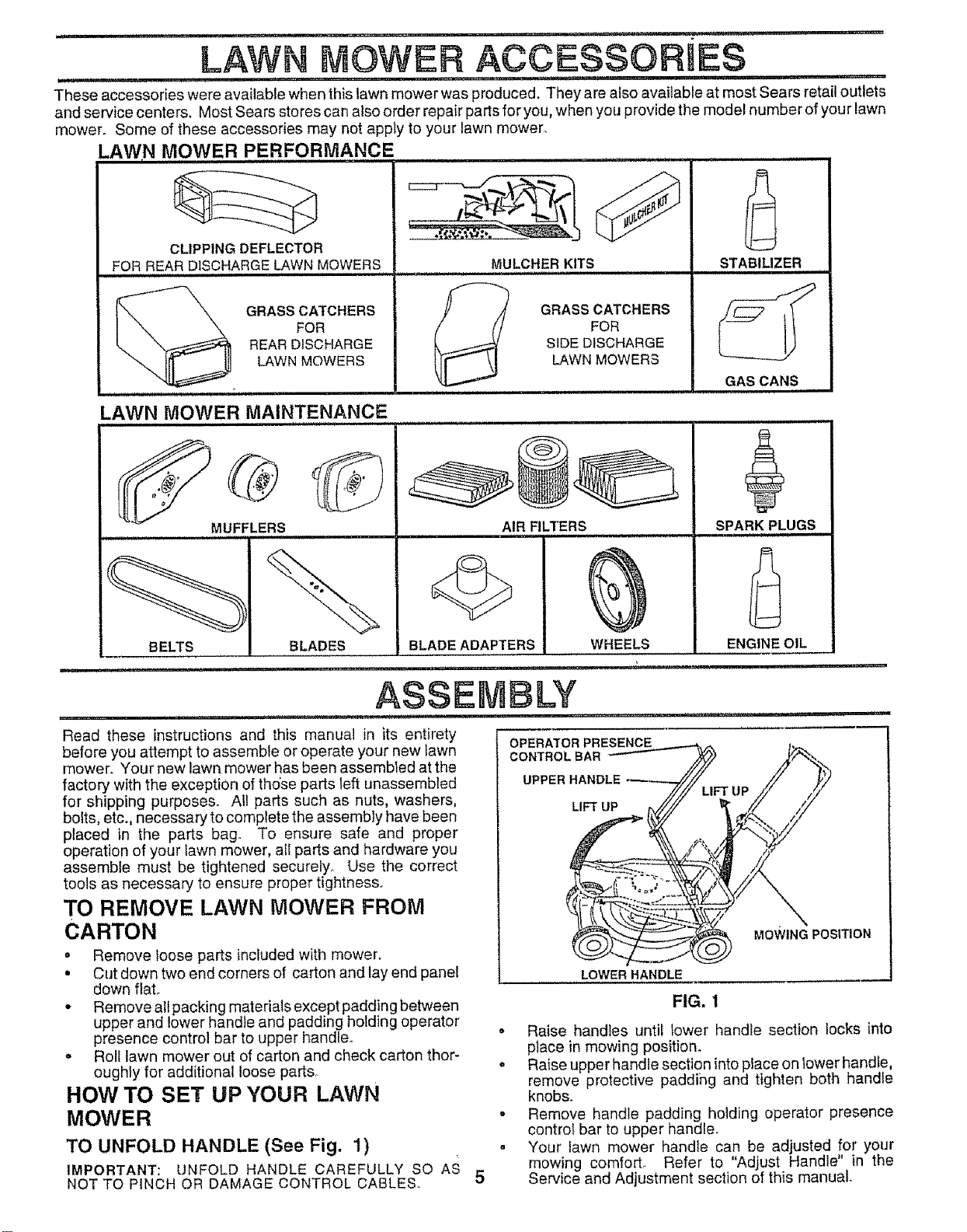
These accessories were available when this lawn mower was produced. They are also available at most Sears retail outlets
and service centers. Most Sears stores can also order repair parts for you, when you provide the model number of your lawn
mower. Some of these accessories may not apply to your lawn mower.
LAWN MOWE R PERFORMANCE ......................
A
LAWN MOWER ACCESSORI
CLIPPING DEFLECTOR
FOR REAR DISCHARGELAWN MOWERS
, ,
GRASS CATCHERS
FOR
REAR DISCHARGE
LAWN MOWERS
LAWN MOWER MAINTENANCE
MULCHERKITS
_'--" ! GRASS CATCHERS
FOR
SIDE DISCHARGE
LAWN MOWERS
............. , ,,, ,,,,,,,,.,,,,
STABILIZER
GAS CANS
i i,, i,n i.,,,,
i
ii L,, ,un i ,u,,
BELTS
MUFFLERS
BLADES
BLADEADAPTERS
i n , ,i iin B ..... .............
ASSEMBLY
...... i,n ,,i, i i .....
Read these instructions and this manual in _ts entirety
before you attempt to assemble or operate your new lawn
mower. Your new lawn mower has been assembled at the
factory with the exception of those parts left unassembled
for shipping purposes. All parts such as nuts, washers,
bolts, etc., necessary to complete the assembly have been
placed in the parts bag. To ensure safe and proper
operation of your lawn mower, all parts and hardware you
assemble must be tightened securely. Use the correct
tools as necessary to ensure proper tightness
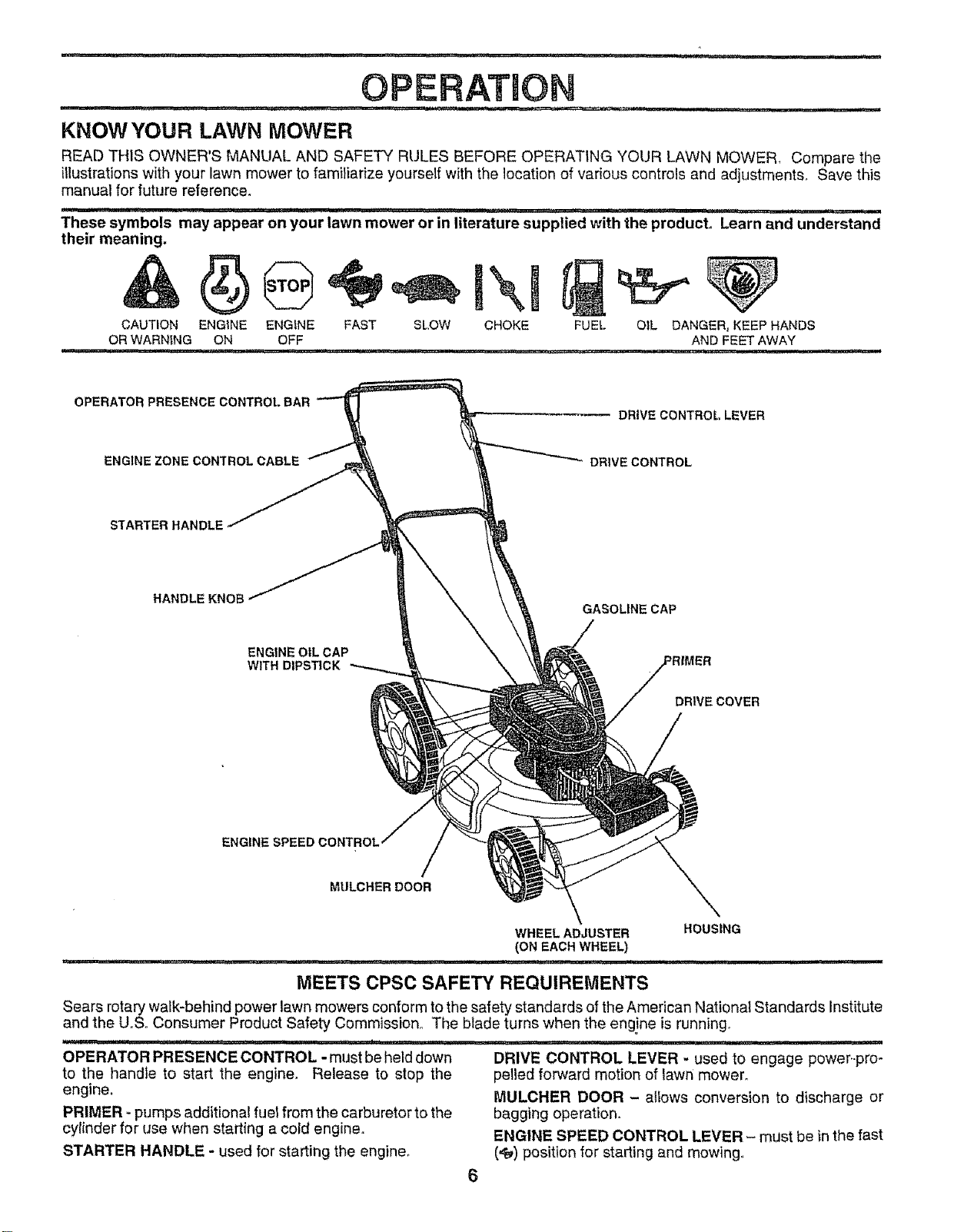
TO REMOVE LAWN MOWER FROM
CARTON
• Remove loose parts included with mower.
• Cut down two end corners of carton and lay end panel
down fiat,
• Remove allpacking materials except padding between
upper and lower handle and padding holding operator
presence control bar to upper handle.
o Roll lawn mower out of carton and check carton thor-
oughly for additional loose part&
HOW TO SET UP YOUR LAWN
MOWER
TO UNFOLD HANDLE (See Fig. 1) =
IMPORTANT: UNFOLD HANDLE CAREFULLY SO AS
NOT TO PINCH OR DAMAGE CONTROL CABLES. 5
AIR FILTERS
i uu ,u
WHEELS
OPERATOR PRESENCE
CONTROLBAR
UPPER
LIFT UP
LOWER HANDLE
u ,, ,u,nll.,
SPARK PLUGS
ENGINE OIL
MOWING POSITION
FIG. 1
• Raise handles until lower handle section locks into
place in mowing position.
• Raise upper handle section intoplace on lower handle,
remove protective paddling and tighten both handle
knobs.
. Remove handle padding holding operator presence
control bar to upper handier,
Your lawn mower handle can be adjusted for your
mowing comfort, Refer to "Adjust Handle" in the
Service and Adjustment section of this manual.
Page 6
i ii i, *
OPERATION
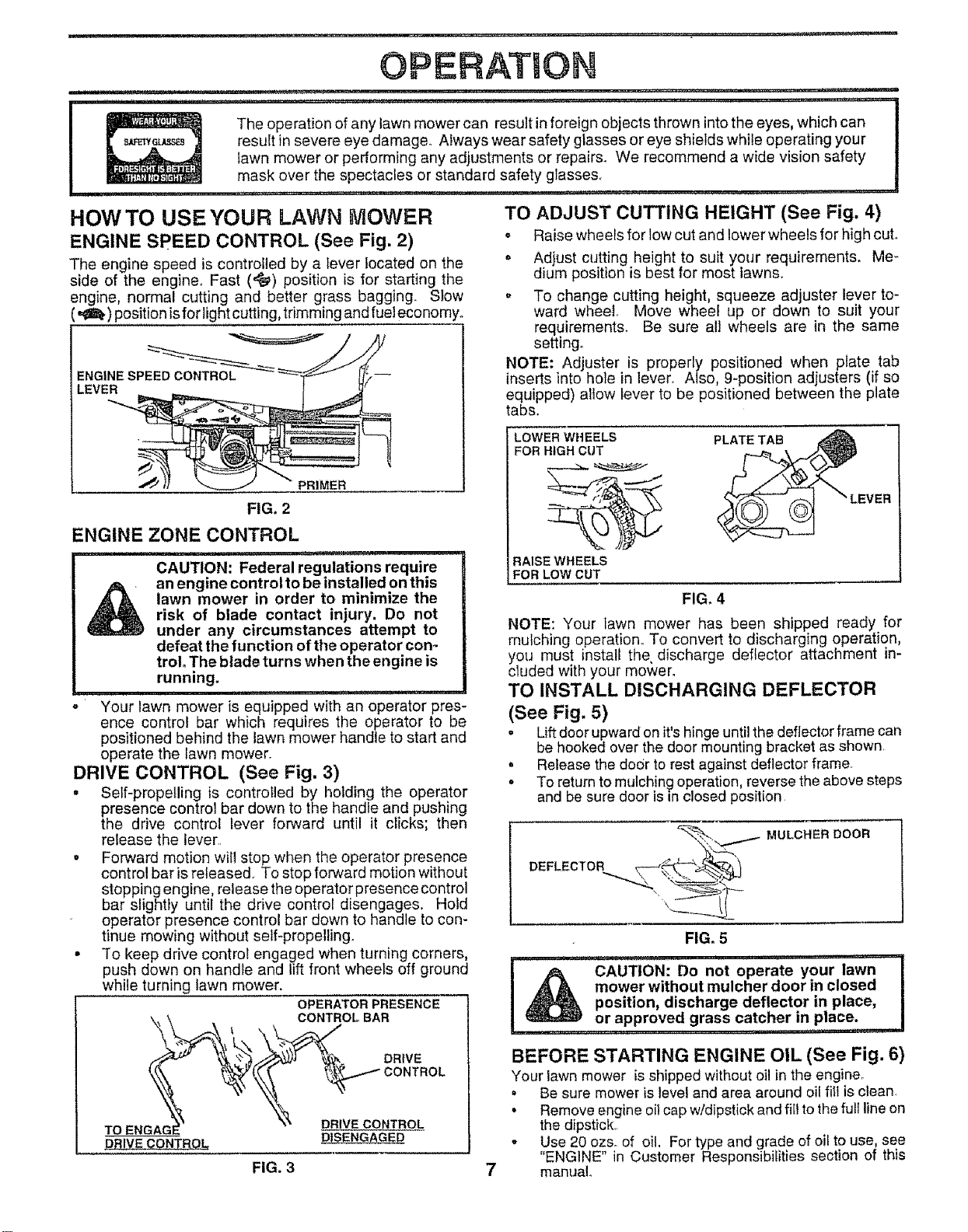
KNOWYOUR LAWN MOWER
READ THIS OWNER'S MANUAL AND SAFETY RULES BEFORE OPERATING YOUR LAWN MOWER_ Compare the
illustrations with your lawn mower to fami)iafize yourself with the location of various controls and adjustments_ Save this
manual for future reference.
........ i = i , ]_ i'"',' . .,,,,.i ,,,,,,,,,,,,,,,,,,, ,,,, _, ,', in nlu I'
These symbols may appear on your lawn mower or in literature supplied with the product. Learn and understand
their meaning.
CAUTION ENGINE
OR WARNING ON
IlL_n I I I' I I :':" :.....
OPERATOR PRESENCECONTROLBAR
ENGINEZONECONTROLCABLE DRIVECONTROL
STARTER HANDLE
HANDLE KNOB
ENGINE OIL CAP
WITH DIPSTICK
FUEL
OIL DANGER, KEEP HANDS
AND FEET AWAY
DRIVE CONTROL, LEVER
GASOLINE CAP
DRIVECOVER
ENGINE SPEED CONTROL
MULCHER DOOR
MEETS CPSC SAFETY REQUIREMENTS
Sears rotary walk-behind power lawn mowers conform to the safety standards of the American National Standards Institute
and the U,,S,,Consumer Product Safety Commission° The blade turns when the engine is running,
OPERATOR PRESENCE CONTROL - must beheld down
to the handle to start the engine. Release to stop the
engine,
PRIMER - pumps additional fuel from the carburetor to the
cylinder for use when starting a cold engine,
STARTER HANDLE - used for starting the engine,
DRIVE CONTROL LEVER - used to engage power.-pro-
pel)ed forward motion of lawn mower.
MULCHER DOOR - allows conversion to discharge or
bagging operation.
ENGINE SPEED CONTROL LEVER - must be inthe fast
(_) position for starting and mowing.
Page 7
OPERATmON
...................... i,,i
i iiiiii i ,, ii, ii i ,;,., ,.... . ...........
_ _!2 The operation of anylawn mowercan result in foreign objects thrown into the eyes, whichcan !
8_Q_._ result in severe eye damage° Always wear safety glasses or eye shields while operating your !
lawn mower or pedorming any adjustments or repairs_ We recommend a wide vision safety i
mask over the spectacles or standard safety glasses.
.............. i
i
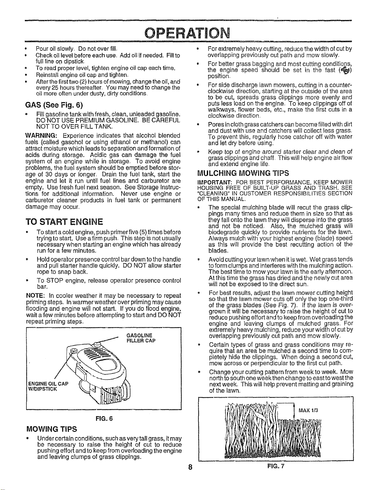
HOW TO USE YOUR LAWN MOWER
ENGINE SPEED CONTROL (See Fig. 2)
The engine speed is controlled by a lever iocated on the
side of the engine. Fast (_) position is for starting the
engine, normal cutting and better grass bagging. Slow
(,_) position isfor light cuttin g,trimming and fuel economyo
=NGINE SPEED CONTROL
LEVER
,_ PRIMER
FIG. 2
ENGINE ZONE CONTROL
CAUTION: Federal regulations require
lawn mower in order to minimize the
risk of blade contact injury. Do not
an engine control to be installed on this
under any circumstances attempt to
defeat the function of the operator con-
trol. The blade turns when the engine is
running.
Your lawn mower is equipped with an operator pres-
ence control bar which requires the operator to be
positioned behind the lawn mower handle to start and
operate the lawn mower.
i ii, ii ....
DRIVE CONTROL (See Fig. 3)
• Self-propelling is controlled by holding the operator
presence control bar down to the handle and pushing
the drive control lever forward until it cticks; then
release the lever.
• Forward motion will stop when the operator presence
control bar is released. To stop forward motion without
stopping engine, release the operator presence control
bar slightly untif the drive control disengages. Hold
operator presence control bar down to handle to con-
tinue mowing without self-propelling.
• To keep drive control engaged when turning corners,
push down on handle and lift front wheels off ground
while turning lawn mower.
OPERATOR PRESENCE
_ CONTROL1 BAR
' oo,w
.oENOAGX X_X OR,VE TROL
DR'VECON.ROL D,SENG O.
FIG, 3 7
TO ADJUST CUTTING HEIGHT (See Fig. 4)
,, Raise wheels for low cut and lower wheels for high cut°
,, Adjust cutting height to suit your requirements. Me-
dium position is best for most lawns.
o To change cutting height, squeeze adjuster lever to-
ward wheel Move wheel up or down to suit your
requirements. Be sure all wheels are in the same
setting..
NOTE: Adjuster is properly positioned when plate tab
inserts into hole in lever. Also g-position adjusters (if so
equipped) allow lever to be positioned between the p ate
tabs.
LOWER WHEELS
FOR HIGH CUT
" LEVER
RAISE WHEELS
FOR LOW CUT
FIG, 4
NOTE: Your lawn mower has been shipped ready for
mulching operation. To convert to discharging operation,
you must install the discharge deflector attachment in-
cluded w th your mower°
TO INSTALL DISCHARGING DEFLECTOR
(See Fig. 5)
o Lift door upward on it's hinge until the deflector frame can
be hooked over the door mounting bracket as shown.
° Release the door to rest against deflector frame.
o To return to mulching operation, reverse the above steps
and be sure door is in closed position.
MULCHERDOOR
DE LECTO.
FIG. 5
i i ii
mower without mulcher door in closed
iAcAoT,oN:oono,opera'eyour"wnI
! i ,, i illl
BEFORE STARTING ENGINE OIL (See Fig, 6)
Your lawn mower is shipped without oil in the engine°
• Be sure mower is level and area around oil fill is clean
• Remove engine oil cap wtdipstick and fill to the full line on
the dipstick..
- Use 20 ozsoof oil. For type and grade of oil to use, see
ENGINE in Customer Responsibilities section of this
manual
position, discharge deflector in place,
or approved grass catcher in place.
Page 8
OPERATION
• Pour oil slowly Do not over fill.
• Check oil level before each use. Add oil ifneeded. Fili to
full line ot_dipstick
o To read proper _evel,tighten engine oil cap each time.
• Reinstall engine oil cap and tighten,
. After the first two (2) hours of mowing, change the oil, and
every 25 hours thereafter You may need to change the
oil more often under dusty, dirty conditions
GAS (See Fig. 6)
• Fill gasoline tank with fresh, clean, unleaded gasoline.
DO NOT USE PREMIUM GASOLINE. BE CAREFUL
NOT TO OVER FILL TANK.
WARNING: Experience indicates that alcohol blended
fuels (called gasohol or using ethanol or methanol) can
attract moisture which leads to separation and formation of
acids during storage. Acidic gas can damage the fuel
system of an engine while in storage, To avoid engine
problems, the fuel system should be emptied before stor-
age of 30 days or ionger_ Drain the fuel tank, start the
engine and let it run until fuel lines and carburetor are
empty. Use fresh fuel next season. See Storage Instruc-
tions for additional information. Never use engine or
carburetor cleaner products in fuel tank or permanent
damage may occur.
TO START ENGINE
. To start acold engine, push primerfive (5) times before
trying to start. Use a firm push This step is not usually
necessary when starting an engine which has already
run for a few minutes.
• Hold operator presence control bar down to the handle
and pull starter handle quickly. DO NOT allow starter
rope to snap back.
• To STOP engine, release operator presence control
bar.
NOTE: In cooker weather it may be necessary to repeat
priming steps. In warmer weather over priming maycause
flooding and engine wiil not start. If you do flood engine,
wait a few minutes before attempting to start and DO NOT
repeat priming steps.
GASOLINE
FILLER CAP
ENGINE OIL CAP
W/DIPSTICK
= For extremely heavy cutting, reduce the width of cut by
overlapping previously cut path and mow slowly,,
• For better grass bagging and most cutting conditio#s,
the engine speed should be set in the fast (@)
position_
, For side discharge lawn mowers, cutting in a counter-
clockwise direction, starting at the outside of the area
to be cut, spreads grass clippings more evenly and
puts less load on the engine° To keep clippings off of
walkways, flower beds, etc., make the first cuts in a
clockwise direction.
- Pores incloth grass catchers can become filled with dirt
and dust with use and catchers will collect less grass_
To prevent this, regularly hose catcher off with water
and let dry before 'using,
o Keep top of engine around starter clear and clean of
grass clippings and chaff. This will help engine airflow
and extend engine life.
MULCHING MOWING TBPS
IMPORTANT: FOR BEST PERFORMANCE, KEEP MOWER
HOUSING FREE OF BUILT-UP GRASS AND TRASH. SEE
"CLEANING" IN CUSTOMER RESPONSIBILITIES SECTION
OF THIS MANUAL,
• The special mulching blade will recut the grass clip-
pings many times and reduce them in size so that as
they fall onto the lawn they will disperse into the grass
and not be noticed, Also, the mulched grass will
biodegrade quickly to provide nutrients for the lawn.
Always mulch with your highest engine (blade) speed
as this will provide the best recutting action of the
blades.
, Avoid cutting your lawn when it,is wet. Wet grass tends
to form clumps and interferes with the mulching action,
The best time to mow your tawn is the early afternoon,
At this time the grass has dried and the newly cut area
will not be exposed to the direct sun.
o For best results, adjust the lawn mower cutting height
so that the lawn mower cuts off only the top one4hird
of the grass blades (See Fig.. 7). If the lawn is over-
grown it will be necessary to raise the height of cut to
reduce pushing effort and to keep from overloading the
engine and leaving clumps of mulched grass. For
extremely heavy mulching, reduce your width of cut by
overlapping previously cut path and mow slowly.
o Certain types of grass and grass conditions may re-
quire that an area be mulched a second time to com-
pletely hide the clippings. When doing a second cut,
mow across or perpendicular to the first cut path.
• Change your cutting pattern from week to week, Mow
north to south one week then change to east to west the
next week. This will help prevent matting and graining
of the lawn.
FIG. 6
MOWING TIPS
. Under certain conditions, such as very tall grass, it may
be necessary to raise the height of cut to reduce
pushing effort and to keep from overloading the engine
and leaving clumps of grass clippings.
MAX 1/3
8 FIG. 7
Page 9

MAINTENANCE SCHEDULE
FILL tN DATES
AS YOU COMPLETE
REGULAR SERVICE
Check for Loose Fasteners
Clean/Inspect Grass Catcher
(If Equipped ) ......
M Clean Lawn Mower
(Power-Propelled Mowers)
O Clean Under Drive Cover
Check drive belt/pulleys
E {Power-Propelfed Mowers)
ChecWSharpen/Repl.ace .Blade
Lubrication Chart
Clean Batted/Recharge
(Electric Start Mowers)
E Check Engine O,i,l,,,Level........
N Change Engine Oil
°e/
v' _/1,2
G clean Air Filter
I inspeCt Muffler
NCiean or Repiace"'Spar'k'"Plug............
E Replace Air Filter Paper Cartridge
1 - Change more often when operating under a heavy _oad or in high ambient temperatures
2 - Service more often when operating in dirty or dus_,y conditions
3 - Replace bfades more olten when mowing in sandy soil
4 - Charge 48 hours at end of season
SERVICE DATES
v'........... I
e,'
......_1_ 3 , , _ _ _-
v'
V'2
GENERAL RECOMMENDATIONS
The warranty on this lawn mower does not cover items that
have been subjected to operator abuse or negligenceo To
receive full value from the warranty, operator must maintain
mower as instructed in this manual
Some adjustments will need to be made periodically to
properly maintain your unit.
All adjustments in the Service and Adjustments section of
this manual should be _hecked at least once each season.
° Once a year, replace the spark plug, clean or replace
air filter element and check btade forwear.. Anewspark
plug and clean/new air filter e!ement assures proper
air4uel mixture and helps your engine run better and
last longer.
° Follow the maintenance schedule in this manual.
BEFORE EACH USE
• Check engine oil level.
• Check for loose fasteners.
LUBRICATION
Keep unit wel! lubricated (See "LUBRICATION CHART"),
LUBRBCAT ON CHART
(D WHEEL,
ADJUSTER
(_BRAKE
(_)MULOHER SPRING
DOOR BRACKET
ENGINE OIL
(_ HANDLE BRACKET
MOUNTING PIN
(_) SPRAY LUBRICANT
(_ REFER TO CUSTOMER RESPONSIBILITIES "ENGINE"
SECTION,
IMPORTANT: DO NOT OIL OR GREASE PLASTIC WHEEL
BEARINGS. VISCOUS LUBRICANTS WiLL ATTRACT
DUST AND DIRT THAT WILL SHORTEN THE LIFE OF
THE SELF LUBRICATING BEARINGS, IF YOU FEELTHEY
MUST BE LUBRICATED, USE ONLY A DRY, POWDERED
GRAPHITE TYPE LUBRICANT SPARINGLY.
Page 10

CUSTOMER
:,,i, i ii i,u,,,,ll i,, ,_,,lUl Jl:_lrl
RESPO
LAWN MOWER
Always observe safety rules when performing any mainte-
nance.
TIRES
o Keep tires free of gasoline, oil, or insect control chemi-
cals which can harm rubber_
° Avoid stumps, stones, deep ruts, sharp objects and
other hazards that may cause tire damage.
BLADE CARE
For best results, mower blade must be kept sharp°
Replace bent or damaged blades.
TO REMOVE BLADE (See Fig. 8)
• Disconnect spark plug wire from spark plug and place
wire where it cannot come in contact with spark plug.
. Turn lawn mower on its side. Make sure air filter and
carburetor are up.
• Use a wood block between blade and mower housing
to prevent blade from turning when removing blade
bolt.
• Protect your hands with gloves and/or wrap bladewith
heavy cloth.
° Remove blade bolt by turning counter-clockwise. Use
a 9/16 box or open-end wrench..
o Remove blade and attaching hardware (bolt, lock
washer and hardened washer).
NOTE: Remove the blade adapter and check the key
inside hub of blade adapter. The key must be in good
condition to work properly. Replace adapter if damaged.
TO REPLACE BLADE (See Fig. 8)
• Position the blade adapter on the engine crankshaft_
Be sure key in adapter and crankshaft keyway are
aligned.
o Position blade onthe blade adapter aligning the two (2)
holes in the blade with the raised lugs on the adapter.
• Be sure the trailing'edge of. blade (opposite sharp
edge) is up toward the engine.
• install the blade bolt with the fock washer and hardene d
,washer into blade adapter and crankshaft.
° Use block of wood between blade and lawn mower
housing and tighten the blade bolt, turning clockwise.
• The recommended tightening torque is 35-40 fL lbs_
IMPORTANT: BLADE BOLT lS GRAD E8 HEAT TREATED.
NOTE: We do not recommend sharpening blade -but ifyou
do, be sure the blade is ba(anced
TO SHARPEN BLADE
Care should be taken to keep the blade balanced. An
unbalanced blade will cause eventual damage to lawn
mower or engine.
o The blade can be sharpened with afile or on a grinding
wheel Do not attempt to sharpen while on the mower
• To check blade baiance, drive a nail into abeam orwall.
Leave about one inch of the straight nait exposed.
Place center hole of blade over the head of the nail If
blade is balanced, it should remain in a horizontal
position, If either end of the blade moves downward,
sharpen the heavy end until the blade is balanced.
LR3"IES
,,, ii
KEY
BLADE
HARDENED
WASHER
LOCK WASHER EDGE BLADEADAPTER
GEAR CASE
. To keep your drive system working properly, the gear
case and area around the drive should be kept clean
and free of trash build-upo Clean under the drive cover
twice a season_
. The gear case is filled with lubricant to the proper level
at the factory. The onfy time the lubricant needs
attention is if service has been performed on the gear
case.
* If lubricant is required, use only Texaco Starplex Pre_
mium Grease, part no. 750355. Do not substitute.
DRIVE WHEELS
Check front drive wheels each time before you mow to be
sure they move free{y.
The wheels not turning freely means trash, grass cuttings,
etc. are in the drive wheel area and must be cleaned to free
drive wheels_
tf necessary to clean the drive wheels, check both front
wheels.
o Remove hubcaps, hairpin cotters and washers,
, Remove wheels from wheel adiusters_
• Remove any trash or grass cuttings from inside the
dust cover, pinion andtor drive wheel gear teeth.
o Put wheels back in place.
o If after cleaning, the drive wheels do not turn freely,
contact your nearest authorized service center.
GRASS CATCHER
(If purchased as an accessory)
o The grass catcher may be hosed with water, but must
be dry when used,
. Check your grass catcher often for damage or deterio-
ration. Through normal use it will wear. If catcher
needs replacing, replace only with a manufacturer
approved replacement catcher.. Give the lawn mower
model number when ordering.
10
............. ,,,,,, .... ii
CRANK-
SHAFT
KE"iWAY
TRAILING
FIG. 8
CRANK-
SHAFT
Page 11

ENGINE
LUBRICATION
Use only high quality detergent oi] rated with API service
classification SF or SG. Select the oil s SAE viscosity grade
according to your expected operating temperature.
=F -20' 0' gO= 32" 40' 80° 60' 188°
°c .3o. -_o= -lo° o° _'o° 20= 30" 4o__L
TEMPERATURE RANGE ANTICIPATED BEFORE NEXT OIL CHANGE
NOTE: Although multi-viscosity oits (5W30, t0W30 etc.)
improve starting in cold weather, these multi-viscosity oils
will result in increased oil consumption when used above
32°F. Check your engine oil level more frequently to avoid
possible engine damage from running low on oil.
Change the oil after the first two hours of operation and
every 25 hours thereafter or at least once a year if the lawn
mower is not used for 25 hours in one year.
Check the crankcase oil level before starting the engine
and after each five (5) hours of continuous use. Tighten oil
plug securely each time you check the oil level,,
TO CHANGE ENGINE OIL (See Fig,, 9)
NOTE: Before tipping lawn mower to drain oil, drain fuel
tank by running engine until fuel tank is empty.
• Disconnect spark p(ug wire from spark plug and place
wire where it cannot come in contact with spark plug.
. Remove engine oil cap; lay aside on a clean surface.
= Tip lawn mower on its side and drain oil into a suitable
container: Rock lawn mower back and forth to remove
any oil trapped inside of engine.
. Wipe off any spilled oit on lawn mower and on side of
engine.
° Fill engine with oil. Fili only to the "FULL" line on the
dipstick. DO NOT OVER FILLo
. Replace engine oil cap.
• Reconnect spark,plug wire to spark plug.
* Insert new filter into cover.
o Put air filter cover and filter into collar aligning the tab
with the slot,
° Push in on cover and turn clockwise to tighten.
CAUTION: Petroleum solvents, such
cartridge. They may cause deteriora-
as kerosene, are not to be used to clean
tion of the cartridge, Do not oil car-
tridge. Do not use pressurized air to
clean or dry cartridge.
o Install cartridge, then repface cover making sure the
tabs are aligned with the slots inthe back plate. Fasten
screw securely.
COLL_, AtR FILTER TURN
. CLI_\
COUNTER-
TO REMOVE
\
SLOT
__ CLOCKWISE
TAB --'-'-" TURN
AIR FILTERCOVER_ TOTIGHTEN
FIG. 10
MUFFLER
Inspect and replace corroded muffler as it could create a
fire hazard and/or damage,
SPARK PLUG
Change your spark plug each year to make your engine
start easier and run better. Set spark plug gap at .030 inch,
CLEANING
IMPORTANT: FOR BEST PERFORMANCE, KEEP
MOWER HOUSING FREE OF BUILT-UP GRASS AND
TRASH° CLEAN THE UNDERSIDE OF YOUR MOWER
AFTER EACH USE,,
CLOCKWISE
\
CONTAINER
FIG. 9
AIR FILTER
Your engine will not run properly and may be damaged by
using a dirty air filter,,
Replace the air fitter every year, more often if you mow in
very dusty, dirty conditions.
TO CLEAN AIR FILTER (See Fig._10)
= Remove the air filter by turning counterclockwise to the
stop and pull away from coItar.
• Remove filter from inside of cover,
= Clean the inside of the cover and the coliar to remove
any dirt accumulation.
" _ CAUTION: oisconnectsparkplu_
from spark plug and placewirewhere it I
cannot come in contact with the spark I
plug. ,...........
° Turn lawn mower on its side. Make sure air filter and
carburetor are up. Clean the underside of your lawn
mower by scraping to remove build-up of grass and
trash.
o Clean engine often to keep trash from accumulating, A
clogged engine runs hotter and shortens engine life.
• Keep finished surfaces and whee}s free of all gasoline,
oil,etc.
° We do not recommend using a garden hose to clean
lawn mower unless the electrical system, muffler, air
filter and carburetor are covered to keep water out.
Water in engine can result in shortened engine life.
CLEAN UNDER DRIVE COVER
Clean under drive cover at least twice a season. Scrape
underside of cover with putty knife or similar tool to remove
11
any build-up of trash or grass on underside of drive cover.
Page 12

..... _ : ,,_.... _..ll,_q ,i, iii i illl,,i _• , ................ ii ii ii , i,i ii1,1, i,i
CE AND ADJUSTMENTS
. i iiiii1,1MII' II, i,
Release control bar°
_ CAUTION: BEFORE PERFORMING ANY SERVICE OR ADJUSTMENTS:
LAWN MOWER
TO ADJUST CUTTING HEIGHT
See "TO ADJUST CUTTING HEIGHT" in the Operation
section of this manual
Make sure the blade and all moving parts have completely stopped.
o
Disconnect spark plug wire from spark plug and place where it cannot come in contact with plug.
.... ..... fj iii, ,1_1 ii iii1,11, ii ,111_ L fl i,
ii ,111,,111,,i i
i ii,,llllll,l.,i, iii
DISCHARGE GUARD
The discharge guard, attached to the discharge opening of
your lawn mower, is provided to prevent the possibility of
injury resulting from objects being thrown out of the dis-
charge opening into the operator mowing position, If the
discharge guard becomes damaged, itshould be replaced,
REAR DEFLECTOR
The rear deflector, attached between the rear wheels of
your mower, is provided to minimize the possibility that
objects will be thrown out of the rear of the mower into the
operator mowing position, tf the deflector becomes dam-
aged, it should be replaced,
TO REMOVE/REPLACE DRIVE BELT
(See Fig, 1'1)
• Remove drive cove_'oRemove belt by pushingdown on
gear case pulley.
• Turn lawn mower on its side with carburetor and fuel
cap up.
o Remove blade,,
- Remove debris shield.
- Remove belt from engine pultey on crankshaft,
• install new belt by reversing above steps°
• Always use factory approved belt to assure fit and long
life.
DRIVE
COVER
BELT
PUS_
DOWN
FIG. 11
12
Page 13

TO ADJUST HANDLE (See Figs. '12 Thru 14)
Your lawn mower handle can be raised or lowered for your
mowing comfort. Four (4) positions are available: high,
medium high, medium tow and low,, Handles are shipped
mounted in the medium low position.
• To change from medium tow to medium high position,
the upper and lower handle sections will have to be
turned over (See Fig° 12B)_
. Remove the controls and operator presence control
bar from the upper handle°
,, Remove the starter rope guide from the lower handle.
• Remove hairpin cotters
o Disconnect the lower handle from the handle brackets
(See Fig, 14)_
° Turn the handle over and reassemble the haffpin
cotters that have been removed,,
o Reassemble the starter rope guide,,
. Reassemble the controls and the operator presence
control bar to the upper handle,.
CAUTION: The operator presence con-
brake engagement when control bar is
released° Do not overtighten the fas-
trol bar must pivot freely to permit blade
teners holding the controls to the up-
per handle.
ii i i l l,l,l,ll, i,i.... i i i i ,i
. To change from medium tow to high position only the
upper handle section will have to be turned over (See
Fig. 13A).
. To change from medium low to low position, only the
lower handle section will have to be turned over (See
Fig_ 13B).
SHIPPING POSITION
MEDIUM LOW
FIG. 12A FIG. 12B
MEDIUM HIGH
LOW
\\
ENGINE
ENGINE SPEED
Your engine speed has been factory set= Do not attempt to
increase engine speed or it may result in personal injury. If
you believe that engine is running too fast or too slow, take
your mower to an authorized service center for repair and
adjustment.
CARBURETOR
Your carburetor is not adjustable If your engine does not
operate properly due to suspected carburetor problems,
take your lawn mower to an authorized service center for
repair and/or adjustment.
IIVlPORTANT: NEVER TAMPER WITH THE ENGINE
GOVERNOR, WHICH IS FACTORY SET FOR PROPER
ENGINE SPEED OVERSPEEDtNG THE ENGINE ABOVE
THE FACTORY HIGH SPEED SETTING CAN BE
DANGEROUS. IF YOU THINK THE ENGINE-GOVERNED
HIGH SPEED NEEDS ADJUSTING, CONTACT YOUR
NEAREST AUTHORIZED SERVICE CENTER, WHICH HAS
PROPER EQUIPMENT AND EXPERIENCE TO MAKE ANY
NECESSARY ADJUSTMENTS,
13
FIG. 13A
\
SQUEEZE
TO REMOVE
HAIRPIN CLIP
FIG. '13B
LOWER HANDLE
HANDLEBRACKET
FIG. 14
Page 14

STORAGE
Immediately prepare your lawn mower for storage at the
end of the season or if the unit will not be used for 30 days ENGINE
or more..
LAWN MOWER
When lawn mower isto be stored for a period of time, clean
it thoroughly, remove all dirt, grease, leaves, etc. Store in
a clean, dry area..
• Clean entire lawn mower (See "CLEANING" in the
Customer Responsibilities section of this manual)°
• Lubricate as shown in the Customer Responsibilities
section of this manual.
• Be sure that all nuts, botts, screws, and pins are
securely fastened Inspect moving parts for damage,
breakage and wear. Replace if necessary°
• Touch up all rusted or chipped paint surfaces; sand
lightly before painting.
HANDLE (See Fig. 15)
You can fold your lawn mower handle for storage.
. Squeeze the bottom ends of the lower handle toward
each other until the lower handle clears the handle
bracket, then move handle forward.
. Loosen upper handle mounting bolts enough to allow
upper handle to be folded back.
IMPORTANT; WHEN FOLDING THE HANDLE FOR
STORAGE OR TRANSPORTATION, BE SURE TO FOLD
THE HANDLE AS SHOWN OR YOU MAY DAMAGE THE
CONTROL CABLES.
= When setting up your handle from the storage position,
the lower hahdte wilt automatically lock into the mowing
position.
LOWER HANDLE
SQUEEZE
TO FOLD
MOUNTING
PiN
FUEL SYSTEM
IMPORTANT: iT tS iMPORTANT TO PREVENT GUM
DEPOSITS FROM FORMING IN ESSENTIAL FUEL
SYSTEM PARTS SUCH AS CARBURETOR, FUEL FILTER,
FUEL HOSE, OR TANK DURING STORAGE. ALSO,
EXPERIENCE iNDICATES THAT ALCOHOL BLENDED
FUELS (CALLED GASOHOL OR USING ETHANOL OR
METHANOL) CAN ATTRACT MOISTURE WHICH LEADS
TO SEPARATION AND FORMATION OF ACIDS DURING
STORAGE. ACIDIC GAS CAN DAMAGE THE FUEL
SYSTEM OF AN ENGINE WHILE IN STORAGE
o Drain the fuel tank.
o Start the engine and tet it run until the fuel lines and
carburetor are empty.
. Never use engine or carburetor cleaner products in the
fuel tank or permanent damage may occur.
. Use fresh fuel next season,
NOTE: Fuel stabilizer is an acceptable alternative in
minimizing the formation of fuel gum deposits during stor-
age. Add stabilizer to gasoline in fuel tank or storage
container. Always follow the mix ratio found on stabilizer
container. Run engine at least 10 minutes after adding
stabilizer to allow the stabilizer to reach the carburetor. Do
not drain the gas tank andcarburetor if using fuel stabilizer.
ENGINE OIL
Drain oil (with engine warm) and replace with clean engine
oil (See "ENGlNE" in the Customer Responsibilities
section of this manual).
CYLINDER
- Remove spark plug.
• Pour one ounce (29 ml) of oil through spark plug hole
into cylinder.
• Pull starter handle slowly a few times to distribute oil.
. Replace with new spark plug,
OPERATOR PRESENCE
CONTROLBAR
UPPER HANDLE
FOLD FORWARD
FORSTORAGE
LOWER HANDLE
HAIRPIN
COTTER
FIG. 15
FOLD BACKWARD
MOWING
POSITION
OTHER
• Do not store gasoline from one season to another..
= Replace your gasoline can if your can starts to rust°
Rust and/or dirt in your gasoline will cause problems°
o If possible, store your unit indoors and cover it to give
protection from dust and dirt,,
o Cover your unit with a suitable protective cover that
does not retain moisture. Do not use plastic. Plastic
cannot breathe which allows condensation to form and
will cause your unit to rust.
IMPORTANT: NEVER COVER MOWER WHILE ENGINE
ANDEXHAUSTAREASAREST LLWARM.
__ CAUTI0_ll Neve'r sto"re the lawnmowe_:: :i
with gasoline in the tank inside a build- |
ing where fumeS may reach an open |
flame or spark. Allow the engine to I
cool before storing in any enclosure. |
,,,_=: ,_,, ,,lit
14
i
Page 15

REPAIR PARTS
ROTARY LAWN MOWER - - MODEL NO. 917.377210
GEAR CASE ASSEMBLY PART NUMBER 702511
J
11
14
I
10
JJ
19
f
17
10
18
KEY PART
NO. NO.
1 17490416
2 137055X004
3 137053
4 57072
6 48373
7 77881
8 137051
9 137074
10 57079
DESCRIPTION
Tapping Screw 1/4-20 x 1-1/4
Engagement Bracket
Shifter
Seat
Gear Case Halves Kit (Includes Key
Nos, 4, 5, and 7)
Bearing
Worm Shaft
Drive Shaft
Hardened Washer
KEY PART
NO. NO. DESCRIPTION
11 131484 Clutch Yoke
12 700343 Bushing
13 86447 Plug
14 137050 Helical Gear
15 750436X Clutch Jaw
16 750369 Grease
17 t2000003 E-Ring
18 850848 Hi-Pro Key
19 8!585X004 Spring Bracket
NOTE: All component dimensions given in U,S, inches_
1 inch = 25.4 mm
15
Page 16

REPAIR PARTS
ROTARY LAWN MOWER - MODEL NO. 917.377210
43
72
35
12_
0'}
72
26
25
35
40
39
48
2
38
42
49
4
52
33
62
56
42
41
51
Page 17

REPAIR PARTS
ROTARY LAWN MOWER - MODEL NO. 917.377210
KEY PART
NO. NO.
t 145646X479
2 STD541425
3 156577
5 153638
7 131959
8 151517
9 51793
10 136376
11 88348
12 t51516X479
t6 STD512505
17 750157
18 15t667X479
,,,4,
19 151665X479
22 140540
23 750097
24 87584X004
25 151889
26 152904
27 147286
28 154132
29 152124
30 751592
31 700168X479
32 700166X479
33 STD523707
35 750085X007
36 146630
38 700331X004
39 701037
40 750913X004
41 61651
42 142748
43 151138
DESCRIPTION
Upper Handle
Locknut
Zone Control Cable
Rope Guide
Handle Bolt
Cable Clip
Hairpin Cotter
Handle Knob
Flat Washer 3/8
Lower Handle
Hex Tapping Screw 1/4-20 x 1/2
Support Rod
Handle Bracket Assembly (Left)
Handle Bracket Assembly (Right)
Rear Deflector
Hex Washer Head Screw #10-24 x 1/2
Deflector Bracket
Discharge Guard
Decal, Mulching Door
Hinge Rod
Housing Bracket
Torsion Spring
Locknut
Support Bracket (Left)
Support Bracket (Right)
Hex Head Bolt 3/8-t6x3/4
Wheel Adjusting Bracket
Spacer
Selector Spring
Selector Knob
Axle Arm Assembly
Belleville Washer
Shoulder Bolt
Wheel & Tire Assembly
KEY PART
NO. NO.
44 57143
45 83923
46 85463
48 14974I
49 STD541425
51 134612
52 150406
53 851084
54 850263
55 85t 074
56 152202
57 851514
58 752!18
59 751399
60 74.180410
62 156516
63 85543
64 87677
68 ......
69 153350X479
70 153282X479
71 63601
72 151440
-- 156525
Available accessories not included with lawn mower:
71 33072
71.___33623
7__!_133500
7__!_133300
7133316
DESCRIPTION
Wave Washer
Locknut 3/18q 6
Danger Decal
Thread Cutting Screw 5/16-18 x 3/4
Hex Locknut
Debris Shield
Hex Head Thread Roiling Screw 3/8-16 x 1-1/8
Hex Head Screw 3/8-24 x 1-3/8 (Grd, 8)
Helical Lockwasher
Hardened Washer
Blade 22"
Blade Adapter
Deflector
Bracket, Deflector
screw 1/4-20
Lawn Mower Housing (Inc!. Ref. #46)
Engine Pulley
Hi-Pro Key #HP 505
Engine - (See Breakdown) Craftsman
Model 143.976250
Support Brkt Handle RH
Support Brkt Handle LH
Locknut Keps
Hubcap
Owner's Manual (English/Spanish)
Grass Catcher
Gas Can (2.5 gaL}
Fuel Stabilizer
SAE 30W Oil (20 oz.)
Mower Cover
Page 18

REPAIR PARTS
ROTARY LAWN MOWER - MODEL NO. 917.377210
28
GO
23
22
21
39
t8
2
30
29
I
!
I
I
Page 19

REPAIR PARTS
ROTARY LAWN MOWER - MODEL NO. 917.377210
KEY PART
NO. NO,
1 145793
2 STD541425
3 48385
4 144929
5 146323
6 146527
9 150495
!2 63601
15 701037
18 88118
19 67725
21 88080
22 137054
23 12000058
24 150340
25 88446
DESCRIPTION
Control Bar
Locknut t/4-20
Control Head Kit
Hex Washer Head Screw
Control Cable Assembly
V-Belt
Spring Retainer
Locknut 1/4-20
Selector Knob
Felt Washer
Washer 1/2x 1-1/2 x.t34
Dust Cover
Pinion
E-Ring
Wheel & Tire Assembly
Wheel Bushing
#t 0-24 x 2-1/8
KEY PART DESCRIPTION
NO. NO.
26 145212
28 150182
29 152903
30 143603
32 15499O
35 48386
36 132010
37 137052
39 75192
41 137090
42 702511
43 152018
44 152019
45 86012
Hex Flange Lecknut
Hubcap
Drive Cover decat
Pan Head Tapping Screw #10-24 x 2-3/4
Drive Cover
Drive Control Cable Kit
Locknut
Drive Pulley
Spring
Spring
Gear Case Assembly (Compoete)
Wheel Adjuster Assembly (Left)
Wheel Adjuster Assembly (Right)
Driveshaft Cover
Page 20

CRAFTSMAN 4=CYCLE ENGINE MODELNUMBER143.976250
261
9OO
2O
Page 21

CRAFTSMAN 4oCYCLE ENGINE MODEL NUMBER 143.976250
KEY PART
NO, NO. DESCRIPTION NO. NO, DESCRIPTION
1 36478A
2 26727
6 33734
7 36557
12A 36558
12B 34695
14 28277
15 30589
16 32651
t7 31335
18 651018
19 36281
20 32600
30 35801
40 36073
40 36074
40 36075
41 36070
41 36071
41 36072
42 36076
42 36077
42 36078
43 20381
45 32875A
46 32610A
48 27241
50 35992
52 29914
69 35261
70 34311D
72 30572
73 28833
75 27897
80 30574A
81 30590A
82 30591
83 30588A
86 650486
89 611004
90 611112
92 650815
93 650816
t00 34443A
101 610118
103 651007
t10 34961
119 36477
120 36476
t25 36471
125 36472
126 29314B
126 29315C
130 6021A
135 35395
150 35991
!51 31673
169 27234A
172 32755
174 30200
178 29752
182 620t
184 26756
Cylinder (lncL 2,7,20 & 125)
Dowel Pin
Breather Element
Breather Ass'y. (Incl. 6 & t2A)
Breather Cover & Tube (Incl. 12B)
Breather Tube Elbow
Washer
Governor Red (Incl. 14)
Govemer Lever
Governor Lever Clamp
Screw, Torx T-15, 8-32 x t9/64"
Extension Spring
Oil Seal
Crankshaft
Piston, Pin & Ring Set (Std.)
Piston, Pin & Ring Set (010" OS)
Piston, Pin & Ring Set (.020" OS)
Piston & Pin Ass'y, (Std.) (fncL 43)
Piston & Pin Ass'y.
(.010" OS) (Incl. 43)
Piston & Pin Ass'y.
(.020" OS) (incl. 43)
Ring Set (Std.)
Ring Set (_010" OS)
Ring Set (.020" OS )
Piston Pin Retaining Ring
Connecting Rod Ass'y. (Incl. 46)
Connecting Rod Bolt
Valve Lifter
Camshaft (MCR)
. Oil Pump Ass'y.
Mounting Flange Gasket
Mounting Flange (Incl. 72 thru 83)
Oi! Drain Plug (Incl. 73)
Drain Plug Gasket
Oil Seal
Governor Shaft
Washer
Governor Gear Ass'y. (lncl 8t)
'Governor Spool
Screw, 1/4-20 x 1-1/4"
Flywheel Key
Flywheel
Bellevilte Washer
Flywheel Nut
Solid State Ignition
Spark Plug Cover
Screw, Torx T-15, 10-24 x 15/t6"
Ground Wire
* Cylinder Head Gasket
Cylinder Head
Exhaust Valve (Std.) (Incl. 151)
Exhaust Valve
(1/32" OS) (IncL 151)
Intake Valve (Std.)(Incl. 151)
Intake Valve (1t32 OS) (lncl. 151)
Screw, 5/16-18 x 1-1/2"
Resistor Spark Plug (RJ19LM)
Valve Spring
Valve Spring Cap
* Valve Cover Gasket
Valve Cover
Screw, 10-24 x 9/16"
Nut & Lock Washer, I/4-28
Screw, 1/4-28 x 7/8"
* Carburetor To Intake Pipe Gasket
KEY PART
185 36544 intake Pipe
188 34337 Governer Link
189 650839 Screw, 1/4-20 x 3/8"
191 36559 &E. Brake Bracket (Incl. 195)
i95 610973 Terminal
200 35727 Control Bracket (Incl. 202 thru 205)
202 36482 Compression Spring
203 31342 Compression Spring
204 650549 Screw, 5-40 x 7/16"
205 650777 Screw, 6-32 x 21/32"
207 34336 Throttle Link
209 30200 Screw, 10-24 x 9/!6"
215 35511 Control Knob
223 650451 Screw, 1/4-20 x 1"
224 34690A * Intake Pipe Gasket
238 650932 Screw, t0-32 x 49/64"
239 34338 * Air Cleaner Gasket
24t 36919 Air Cleaner Collar
245 36905 Air Cleaner Filter
250 36920 Air Cleaner Cover
260 36915 Blower Housing
261 30200 Screw, 10-24 x 9/16"
262 650831 Screw, 1/4-20 x 1/2"
263A 36921 Starter Grill
275 36473 Muffler (Incl. 277)
277 650988 Screw, 1/4-20 x 2-5/16"
285 35000A Starter Cup
287 650926 Screw, 8-32 x 2t/64"
290 29774 Fuel Line
292 26460 Fuel Line Clamp
298 28763 Screw, 10-32 x 35164"
300 36916 Fuel Tank (IncL 292 & 301)
30t 36246 Fuel Cap
305 35647 Oil FillTube
306 36832 * "O"-Ring
307 35499 "O"-Ring
309 650562 Screw, I0-32 x 1/2"
310 35648 Dipstick
313 34080 Spacer
347 651038 Screw, 10-32 x 51/64"
370A 36261 Lubrication Decal
370B 35167 Control Decal
370C 36861 Primer Decal
380 632747 Carburetor (lncl,, 184)
390 590702 Rewind Starter
400 36481 Gasket Set
(IncL Items Marked * in Notes)
416 36085 Spark Arrestor Kit
(IncL 416)(Optional)
417 650760 Screw, 8-32 x 3t8" (Optional)
900 _ Replacement Engine 750784A,
order from 71-999
900 -_ ";Replacement S/B 750670A,
_order from 71-999
RPM High 2900 to 3200
RPM Low 2450 to 2750
(NOTE: This engine could have been built with 590739
starter, Refer to the design of the rope pulley strength
ribs for part identification. Individual starter parts do not
interchange.) Incl. part #'s 26756 (1),27234A (1), 33735
(1), 36832 (I), 34338 (1), 34690A (1), 35261 (1),
36477 (1)
NOTE: All component dimensions given in U.S. inches
1 inch = 25.4 mm
21
Page 22

CRAFTSMAN 4-CYCLE ENGINE MODELNUMBER143.976250
" NO, NO, DESCRIPTION
,._-_ _ _, -- 632747 Carburetor
,_ty _ " (lncL 184 of Engine Parts List)
KEY PART
2 631767 Throttle Return Spring
__ I 63t6t5 Throttle Shaft & Lever Assembly
4 631184 Dust Seal Washer
5 631183 Dust Seal (Throttle)
"" 7 650506 Shutter Screw
6 632504 Throttle Shutter
25 631867 Float Bowl
_.. 16 631807 Fuet Fitting
" 27 631024 Float Shaft
=" 28 632019 Float
+"" 29 631028 Float Bowl "O" Ring
.,,, 30 631021 Inlet Needle, Seat, & Clip (Incl. 31)
,_..,, 31 631022 Spring Clip
36 632735 Main Nozzle Tube
_" 37 632547 "0" Ring, Main Nozzle Tube
,_ 40 632736 High Speed Bowl Nut
35 36045 Primer Bulb/Retainer Ring
44 27110 Bowl Nut Washer
48 631027 Welch Plug, Atmospheric Vent
i i ii, ii n i n ,,lllll uuuul,,_, , i
KEY PART
-- 590702 Recoil Starter
,, " 1 590599A Spring Pin (Incl, 4)
___ NO. NO. DESCRIPTION
2 590600 Washer
3 590696 Retainer
_, 5 590697 Brake Spring
6 590698 Starter Dog
4 590601 Washer
7 590699
'-_ _--, 8 590700 Pulley & Rewind Spring Ass'y,
11 590703 Starter Housing Ass'y,
'-_ _ _ 12 590535 Starter Rope ( 98" X 9/64" dia,,)
Dog Spring
(40 degree grommet)
13 590701 Starter Handle
i _ _i_ ii_ i....................... _ii _ii iii_ii_l
V.... KEY PART
NO, NO. DESCRIPTION
-- 590739 Rewind Starter
3 590740 Retainer
6 590616 Starter Dog
7 590617 Dog Spring
8 590618A Pulley & Rewind Spring Ass'y
1t 590638 Starter Housing Ass'y
(40 degree grommet)
12 590535 Starter Rope
(Length 98" x 9/64" dia.)
t3 590701 Starter HandLe
14 590741 Locking Tab
€1 I!-'
NOTE: All component dimensions given in U,S, inches
1 inch = 25,,4 m
22
Page 23

PROBLEM
Does not start
CAUSE
=
1. Dlrty air filter
2_ Outof fuel
3 Stale fuel.
4. Water in fueL
5. Spark plug wire ts disconnected_
6. Bad spark pfug.
7. Loose btada or broken blade adapter
8, Control bar In re!eased posttton
9. Control bar defective
CORRECTION
t Clearu'raplace air fitter
2 FHIfuel tank
3 Drain tank and refill with fresh clean fuel.
4 Drain fuel tank and carburetorand rafi!l tank with fresh
gasoline,
5 Connect wire to plug
6. Replace spark plug.
7. Tighten blade bolt or replace blade adapter.
8 Depress control bar to handle.
9. Replace control bar
Loss of power
Poor cut - uneven
Excessive vibration
==
Starter rope hard to pull
Loss of drive
(Self-Propelled Mowing)
Grass catcher not filling
(If so equipped)
1, Rear of Iawn mower housingZolade dragging
In heavy grass,
2, Cuing too much grass
3 Dirty air filter
4. Bultdup of grass, leaves and trash under mower
5 Too much oi_in engine.
6. Walking speed too lasto
1 Worn, bent er ioose blade.
2, Wheel heights uneven,
3 Low engine speed,
4 Buildup of grass, leaves, and trash under mower,
1, Worn, bent or loose blade,
2, Bent engine crankshaft,
1. Engine flywheel brake is on when control bar is
released.
2_ Bent engine crankshaft
3 Btads adapter broken.
4. Blade dragging in grass
1. Ddve wheels not tumtng with ddve control engaged.
•2. Bait not ddving.
1,, Cutting height too lewd
2 Lift on blade worn off,,
3. Catcher not venting aLr,
4. Low engine speed
1. Set in "Higher Cut-" position.
2, Set in "Higher Cut" position
3. Clean/replace air fitter
4,, Clean underside of mower housing.
5, Check otIlevel
6, Cut at slower walking spee&
1, Replace blade, Tighten btade bolt.
2. Set elf wheels at same height
3 Set engine speed control in fast position,
4_ Clean underside of mower housing,
t. Replace blade, Tighten blade bott
2 Contact an authorized service centerldepartmenL
....._,, , ...... ....... ', ............. "7
t. Depress control bar to upper handle before
pulling starter rope
2. Contact an authorized service center/department
3. Replace blade adapter
4. Move lawn mower to cut grass or to hard surface
to start engine.
1.= Adjust or replace drive control cable, if broken
2 Put belt on pulleys or replace belts tf broken
1 Raise cutting height.
2, Replace blade.
3 CIean grass catcher
4 Set engine speed controltn fast position
Hard to push
f,
Grass is too high or wheel height ts too tow,
2,
Rear of lawn mower housing/blade dragging
in grass.
3,,
Grass catcher too full
4
Hand]a helght position not dght for you.
1 Raise cutting height.
2 Raise rear of lawn mower housing one (1)
selling higher°
3 Empty grass catcher,
4 Adjust handle height to suit.
23
Page 24

,i , i,l,ii i i i± LI ELIll IJIIIllllII II I '1 I I1' I I'll'll, I I III '11 I I I
' •............................................ i IlL / I L
SERVICE NOTES
24
 Loading...