

Page 1
NUMBER917.3722
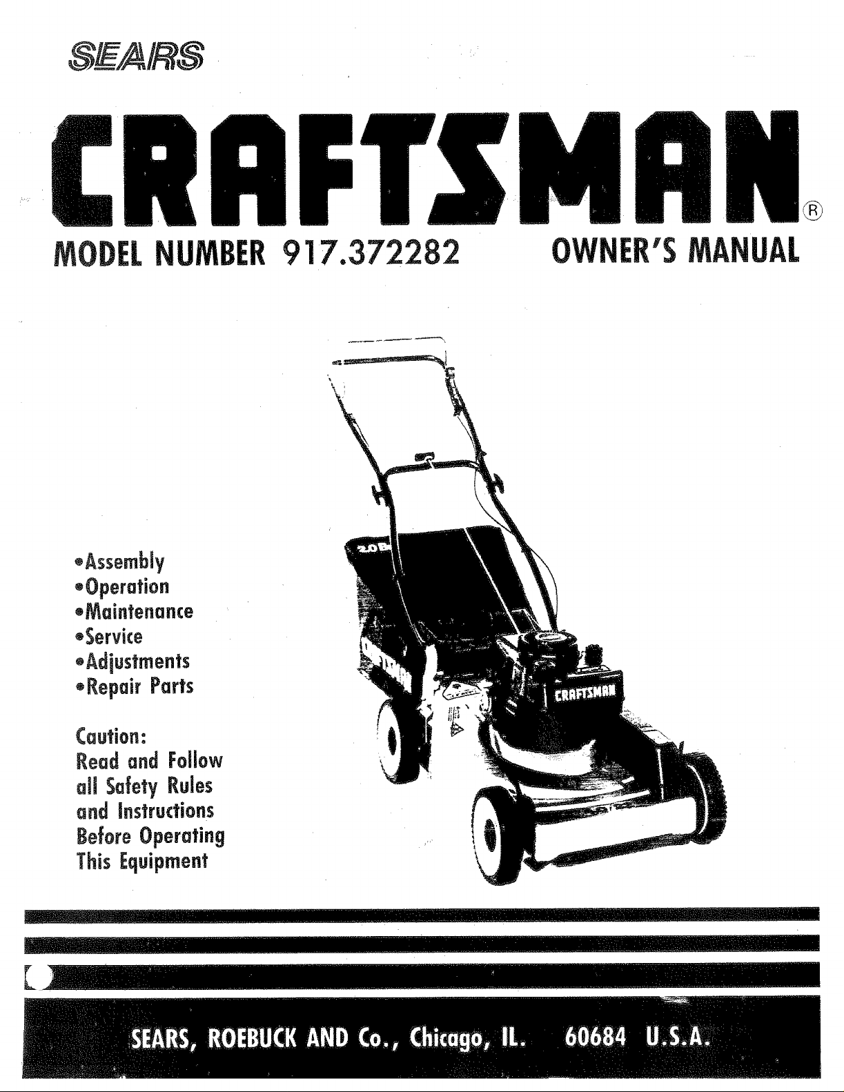
.Assembly
*Operation
.Maintenance
.Service
2 OWNER'SMANUAL
.Adiustments
*RepairParts
Caution:
Read and Follow
aimSafety Rules
and Instructions
BeforeOperating
This Equipment \
_ _,,, _ t,nn Jn [l!l............... I ! I I1.................................
Page 2
SAFETYRULES
CAUTION: ALWAYS DISCONNECT SPARK PLUG WIRE AND PLACE WIRE
WHERE IT CANNOT CONTACT SPARK PLUG TO PREVENT ACCIDENTAL STAR-
TING WHEN SETTiNG-UP, TRANSPORTING, ADJUSTING OR MAKING
REPAIRS TO YOUR LAWN MOWER.
:IMPORTANT
FEDERAL REGULATIONS REQUIRE OPERATOR PRESENCE BLADE STOP CONTROLS TO MINIMIZE THE
RISK OF BLADE CONTACT INJURY. YOUR LAWN MOWER IS EQUIPPED WITH SUCH CONTROLS. DO
NOT ATTEMPT TO DEFEAT THE FUNCTION OF THE OPERATOR PRESENCE CONTROL UNDER ANY
CIRCUMSTANCES.
" BE CAREFUL-WHEN THE ENGINE IS RUN-
NiNG THE BLADE IS TURNING.
• Please read your owner's manual. Only allow
persons who know the safety rules to use your
lawn mower. _;,,'_,
• DO NOT fie the operator presen_ €o_trbl bar
to the handle. Control must be ffeelt6 permit
brake engagement when handles ai_d control
are released. ;;
• DO NOT allow childre_iii_i_iii_;_i_' your lawn
mower. ; i
• Check your lawn mower ove_;_efore each use.
Tighten any loose bolts, nuts, etc.
• Remove all sticks,;stc_nes_ wires, cans, boards,
etc. from area to be m_ed. These objects can
be thrown by:the blad:e.
• DO NOT allow children, bystanders or pets in
the area v_hile mowing.
• Always w;ar :shoes when mowing. DO NOT
operate tawn m_wer when barefoot or wear-
ing open safidafs.
Alway s wedr safety glasses or eye shields
before starting your lawn mower and while
mowing.
° Always shut off engine before trying to adjust
wheelheights.
• When engine is running, DO NOT put hands
or feet under lawn mower or in the discharge
chute, nor make any adjustments.
° Stay clear of discharge opening at all times.
• Do not fill gas tank when engine is running,
when indoors or when engine is hot. Allow
engine to cool for several minutes before fill-
ing gas tank. Clean off any spilled gasoline
before starting engine.
• Mow only in good light.
• Always stop blade when not cutting grass or
when crossing gravel drive, sidewalk, or
roadway.
i i ,,¸ ...............
LOOKFORTHISSYMBOLTO
TANTSAFETYPRECAUTIONS.
TION!!! BECOME ALERT!!!
INVOLVED.
° DO NOT continue to run your lawn mower if
you hit a foreign object. Stop the engine,
disconnect the spark plug wire from the spark
plug, inspect the lawn mower for damage and
make repairs as required.
° DO NOT use a damaged lawn mower. Always
have damage repaired before mowing.
. DO NOT run your lawn mower if it vibrates
too much. Stop engine and make repairs.
Vibration is an indication of damage.
° Never use your lawn mower without proper
guards or deflectors in place.
• Always mow across a slope or inclined area.
DO NOT mow up or down a slope or inclined
area.
• DO NOT mow in wet grass. Be careful of
footing when mowing in wet grass, use shoes
with good traction.
• DO NOT run with the lawn mower
- DO NOT run your lawn mower indoors Ex-
haust gases are deadly poison.
• Always disconnect the spark plug wire from
spark plug to prevent accidental starting when
transporting or storing your lawn mower after
the mowing season.
° DO NOT attempt to raise engine speed above
factory settings. Engine damage or personal
injury may result.
o If a grass catcher is used on your lawn mower,
check the catcher often for damage or
deterioration, it wilt wear through normal use.
Use only a recommended replacement catcher.
. Always stop blade to remove or install catcher.
° DO NOT store your lawn mower or gasoline
where fumes may reach an open flame and
cause a fire.
• DRAIN THE GASOLINE from your lawn
mower before transporting your lawn mower
inside your car or other vehicle.
POINT OUT IMPOR-
IT MEANS-- ATTEN-
YOUR SAFETYIS
Page 3
CONGRATULATIONSon your purchase of a Sears Crafts-
man Lawn Mower° It has been designed, engineered
and manufactured to _ive you the best possible
dependability and perTormance.
Should you experience any problem you cannot easi-
ly remedy, please contact your nearest Sears Ser-
vice Center!Department. We have competent, well-
trained technicians and the proper tools to service
or repair this unit°
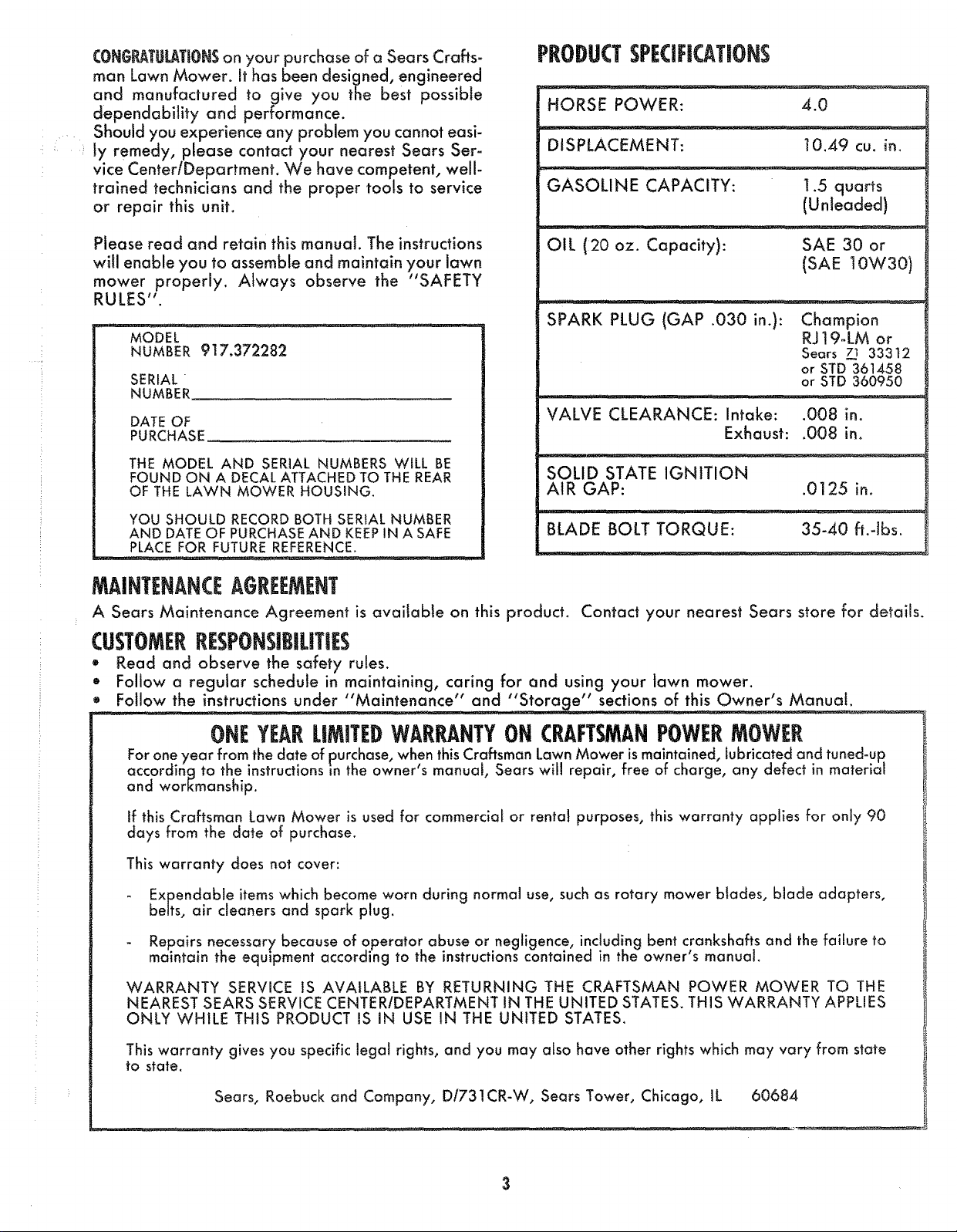
PEODUCTSPECIFICATIONS
HORSE POWER: 4.0
DISPLACEMENT: 10.49 cu. in.
GASOLINE CAPACITY: 1.5 quarts
(Unleaded)
Please read and retain this manual. The instructions
will enable you to assemble and maintain your lawn
mower properly. Always observe the "SAFETY
RULES".
OIL (20 oz. Capacity): SAE 30 or
(SAE10W30)
SPARK PLUG (GAP .030 in.): Champion
MODEL
NUMBER 917.372282
SERIAL
NUMBER
DATE OF
PURCHASE
THE MODEL AND SERIAL NUMBERS WILL BE
FOUND ON A DECAL ATTACHED TO THE REAR
OF THE LAWN MOWER HOUSING.
YOU SHOULD RECORD BOTH SERIAL NUMBER
AND DATE OF PURCHASE AND KEEP IN A SAFE
PLACE FOR FUTURE REFERENCE.
VALVE CLEARANCE: Intake: .008 in.
Exhaust: .008 in°
SOLID STATE IGNITION
AIR GAP: .0125 in.
BLADE BOLT TORQUE: 35-40 ft.-Ibs.
RJ 19_LM or
Sears _ 33312
or STD 361458
or STD 360950
MAINTENANCEAGEEEMENT
A Sears Maintenance Agreement is available on this product. Contact your nearest Sears store for details.
CUSTOMEERESPONSIBILITIES
• Read and observe the safety rules.
• Follow a regular schedule in maintaining, caring for and using your lawn mower.
• Follow the instructions under "Maintenance" and "Storage" sections of this Owner's Manual.
ONEYEARLIMITEDWAERANTYONCRAFTSMANPOWER OWEP,
For one year from the date of purchase, when this Craftsman Lawn Mower ismaintained, lubricated and tuned-up.
accordinq to the instructions m the owner's manual, Sears will repair, free of charge, any defect in material
and workmanship.
ff this Craftsman Lawn Mower is used for commercial or rental purposes, this warranty applies for only 90
days from the date of purchase.
This warranty does not cover:
Expendable items which become worn during normal use, such as rotary mower blades, blade adapters,
belts, air cleaners and spark plug.
- Repairs necessary' because of operator abuse or negligence, including bent crankshafts and the failure to
maintain the equipment according to the instructions contained in the owner's manual.
WARRANTY SERVICE IS AVAILABLE BY RETURNING THE CRAFTSMAN POWER MOWER TO THE
NEAREST SEARS SERVICE CENTER/DEPARTMENT IN THE UNITED STATES. THIS WARRANTY APPLIES
ONLY WHILE THIS PRODUCT IS IN USE IN THE UNITED STATES.
This warranty gives you specific legat rights, and you may also have other rights which may vary from state
to state.
Sears, Roebuck and Company, D/731CR-W, Sears Tower, Chicago, tL 60684
Page 4
TABLEOFCONTENTS
SAFETY RULES ....................... 2
PRODUCT SPECIFICATIONS ............. 3
CUSTOMER RESPONSIBILITIES . 3
WARRANTY .......................... 3
LAWN MOWER ACCESSORIES ........... 5
ASSEMBLY ........................... 6
OPERATION ..................... 7,8,9, !0
MAINTENANCE ................. 11,12,13
A
Adjustments:
Carburetor ................. 14
Engine Speed ............. 15
Handle Height .............. 15
Height oF Cut ................ 9
Air Filter:
Replacement .............. 12
Assembry:
Handle .................. 6
Accessories .................. 5
B
Blade:
Replacement ............... 11
Sharpening ................ 11
Controls:
Drive Control .............. 7,8
Engine Zone Control ......... 7,8
Engine Speed Control ....... 7,8
Operator Presence Control Bar .. 7
Customer Responsibilities ........ 3
Cuffing Levels ............... 9
Handle:
Adjustment ................. 15
Assembly ................... 6
Height, Cutting .............. 9
Lubrication:
Brake Spring Bracket ......... 17
Engine .................... 17
Handle Bracket Pin .......... t7
Rear Door Hinge ............ 17
Wheel Adjuster ............. 17
Maintenance:
Agreement .................. 3
Air Filter .................. 12
Blade Care/Repiacement ..... 11
Engine ................... 12
Grass Catcher ............. 12
Lubrication ................ 17
Spark Plug ................ t3
Mowing Tips ................ 10
SERVICE AND ADJUSTMENT ......... 14&15
STORAGE ............................ 16
SERVICE RECOMMENDATIONS .......... t7
REPAIR PARTS.LAWN MOWER ........ 18-21
REPAIR PARTS-ENGINE .............. 22.25
TROUBLE SHOOTING .................. 26
PARTS ORDERING/SERVICE ...... Back Cover
Safety Rules .................. 2
Service and Adjustments:
Carburetor ................. 14
Engine Speed .............. 15
Drive Belt ................. 14
Handle ................... 15
Rear Deflector .............. 15
Service Recommendation ....... 17
Spark Plug .................. 13
Specifications ................. 3
Speed Control:
Engine ................... 7,8
Starting the Engine:
Starter Handle .............. 10
Storage ..................... 16
M
T
Trouble Shooting Chart ......... 26
W
Warranty .................... 3
Wheels:
Wheel Adjusters ........... 7,17
0
Engine:
Oil Change ................ 12
Oi! Levet .................. 9
Oil Type .................. 9
Starting ................... 10
Storage ................... 16
Fuel:
Capacity ................... 3
Type .................... 9
Storage ................... "I6
Oil:
Engine .................... 9
Storage .................. ] 6
Operation:
Operating Lawn Mower .... 7-10
Operator Presence Control ..... 7
Options:
Attachments ................ 5
Parts .................... ! 8-25
Engine ................. 22-25
Lawn Mower ............ 18-21
Primer ................... 7,10
Page 5
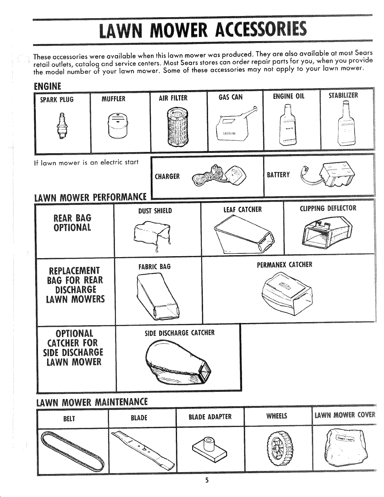
. These accessories were available when this lawn mower was produced. They are also available at most Sears
retail outlets, catalog and service centers. Moss Sears stores can order repair parts for you, when you provide
the model number of your lawn mower. Some of these accessories may not apply to your lawn mower_
ENGINE
ecd_
SPAREPLUG MUFFLER Ale FILTER GASCAN ENGINEOiL STABILIZER
if ]awn mower is an electric start
LAWNMOWERPERFORMANCE
DUSTSHIELD
REARBAG
OPTIONAL
REPLACEMENT
FABRICBAG
BAGFORREAR
DISCHARGE
LAWNMOWERS
OPTIONAL
SIDE DISCHARGECATCHER
CATCHERFOR
SIDEDISCHARGE
LAWNMOWER
• .. .. _
LAWN_OWERMAINTENANCE
CLIPPING DEFLECTOR
PERMAHEXCATCHER
,I
BELT BLADE BLADEADAPTER
5
WHEELS
LAWN MOWER COVER
Page 6
ASSEMBLY
..... ___ !lUl II'll ............................ ,.___ '
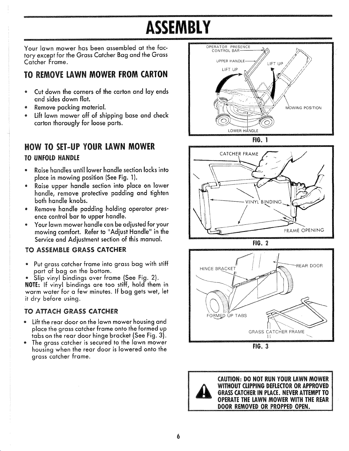
Your lawn mower has been assembled at the fac-
tory except for the Grass Catcher Bag and the Grass
Catcher Frame.
TOREMOVELAWNMOWERFROMCARTON
• Cut down the corners of the carton and lay ends
and sides down fiat.
o Remove packing material.
• Lift lawn mower off of shipping base and check
carton thorougly for loose parts.
HOWTOSET-UPYOURLAWNMOWER
TO UNFOLDHANDLE
0 Raise handles until lower handle section locks into
place in mowing position (SeeFig. 1).
Raise upper handle section into place on lower
handle, remove protective padding and tighten
both handle knobs.
• Remove handle padding holding operator pres-
ence control bar to upper handle.
- Your lawn mower handle can be adjusted for your
mowing comfort. Refer to "Adjust Handle" in the
Service and Adjustment sectionof this manual.
TO ASSEMBLE GRASS CATCHER
OPERATOR PRESENCE
CONTROL BAR
\
UPPER
LIFT UP
MOWING POSITION
CATCHER FRAME
FRAME OPENING
FI6. 2
i Iq u' '1I"'l'lq I
o Put grass catcher frame into grass bag with stiff
part of bag on the bottom.
® Slip vinyl bindings over frame (See Fig. 2).
NOTE: If vinyl bindings are too stiff, hold them in
warm water for a few minutes. If bag gets wet, let
it dry before using.
TO ATTACH GRASS CATCHER
* Lift the rear door on the lawn mower housing and
place the grass catcher frame onto the formed up
tabs on the rear door hinge bracket (See Fig. 3).
The grass catcher is secured to the lawn mower
housing when the rear door is Jowered onto the
grass catcher frame.
HINGE BRACKET _/ __*_---REAR DOOR
FORME._¢D UP TABS
GRASS
FIO. 3
CAUTION: DO NOT RUN YOURLAWN mOWER
ORASSCATCHERIN PLACE.NEVERATTEMPTTO
WITHOUTCLIPPINGDEFLECTOROR APPROVED
OPERATETHE LAWNmOWER WITH THEREAR
DOOR REMOVEDOR PROPPEDOPEN.
6
Page 7
OPERATION
KNOWYOURLAWNMOWER
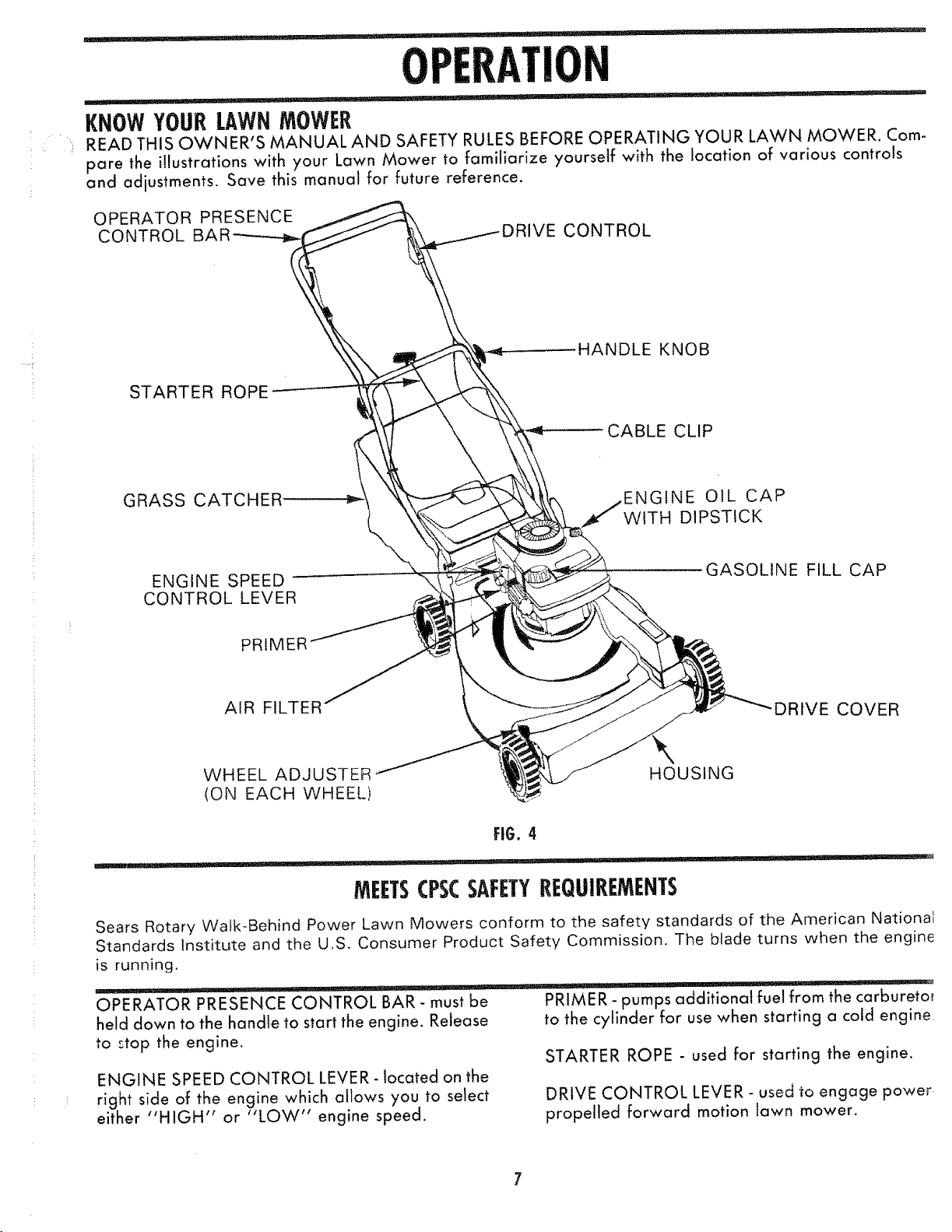
READ THIS OWNER'S MANUAL AND SAFETY RULES BEFORE OPERATING YOUR LAWN MOWER. Com-
pare the illustrations with your Lawn Mower to familiarize yourself with the location of various controls
and adjustments. Save this manual for future reference.
OPERATOR PRESENCE
CONTROL E CONTROL
HANDLE KNOB
STARTER ROPE
CABLE CLIP
GRASS CATCHER
ENGINE SPEED
CONTROL LEVER
PRIMER
AIR FILTER
WHEEL ADJUSTER
(ON EACH WHEEL)
GfNE OiL CAP
WITH DIPSTICK
GASOLINE FILL CAP
DRIVE COVER
HOUSING
FIG. 4
MEETSCPSCSAFETYREQUIREMENTS
Sears Rotary Walk-Behind Power Lawn Mowers conform to the safety standards of the American National
Standards Institute and the U,S. Consumer Product Safety Commission. The blade turns when the engine
is running.
OPERATOR PRESENCE CONTROL BAR- must be
held down to the handle to start the engine. Release
to :top the engine.
ENGINE SPEED CONTROL LEVER- located on the
right side of the engine which allows you to select
either "HIGH" or "LOW" engine speed.
PRIMER - pumps additional fuel from the carburetor
to the cylinder for use when starting a cold engine
STARTER ROPE - used for starting the engine.
DRIVE CONTROL LEVER- used to engage power
propelled forward motion lawn mower.
Page 8
HOWTOUSEYOURLAWNMOWER
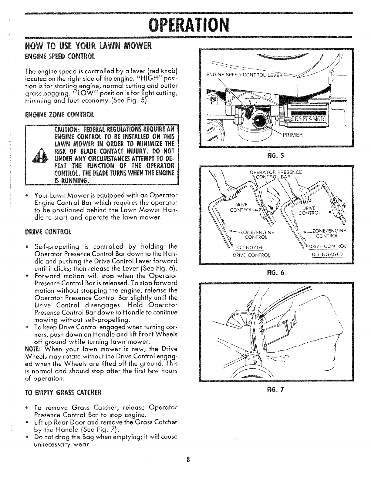
ENGINESPEEDCONTROL
The engine speed is controlled by a lever (red knob)
located on the right side of the engine. "HIGH" posi-
tion is for starting engine, normal cutting and better
grass bagging. "LOW" position is for light cutting,
trimming and furl economy (See Fig. 5).
ENGINEZONECONTROL
T
CAUTION: FEDERALREGULATIONSREQLIIREAN
ENGtNECOHTROLTO 8E INSTALLEDON THIS
LAWN MOWER IN ORDERTO MBHIMiZE THE
RtSE OF gLADE COHTACTJNJLtR¥_ DO NOT
UNDERANY GRCgMSTANCESATTEMPTTO DE-
F_,_T THE FUNCTION OF THE OPERATOR
CONTROL,THEBL_OETLtRHSWHENTHEENGINE
!$ RUNNING.
Your Lawn Mower is equipped with an Operator
Engine Control Bar which requires the operator
to be positioned behind the Lawn Mower Han-
dle to start and operate the lawn mower.
I)RIVE CONTROL
• Self-propelling is controlled by holding the
Operator Presence Control Bar down to the Han-
dle and pushing the Drive Control Lever forward
until it clicks; then release the Lever (See Fig. 6).
® Forward motion will stop when the Operator
Presence Control Bar is released. To stop forward
motion without stopping the engine, release the
Operator Presence Control Bar slightly until the
Drive Control disengages. Hold Operator
Presence Control Bar down to Handle to continue
mowing without self-propdling.
o To keep Drive Control engaged when turning cor-
ners, push down on Handle and lift Front Wheels
off ground while turning lawn mower.
NOT_: When your lawn mower is new, the Drive
Wheels may rotate without the Drive Control engag-
ed when the Wheals are lifted off the ground. This
is normal and should stop after the first few hours
of operation.
TO EMPTYGRASSCATCHER
PRIMER
CONTROL
DRIVE CONTROL DtSENGAGED
Ft$. 6
/
'L
Ft6.7
To remove Grass Catcher, release Operator
Presence Control Bar to stop engine.
, Lift up Rear Door and remove the Grass Catcher
by the Handle (See Fig. 7).
* Do not drag the Bag when emptying; it wiJf cause
unnecessary wear.
Page 9
OPERATION
-' ___ ....... _z_::_ __ '!l I I iI lllll, i I iiiii ii ll,lrlll,,ll, i i'i ii,, ..............
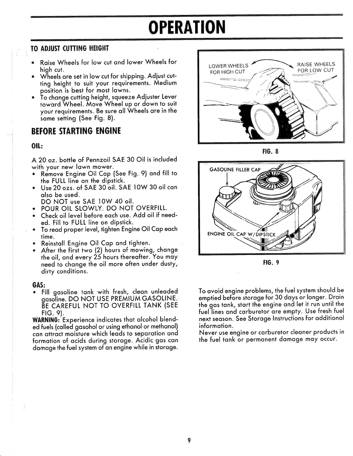
TO ADJUST CUTTING HEIGHT ........ _ _ +
° Raise Wheels for low cut and lower Wheels for
high cut+
+ Wheels are set in low cut for shipping. Adjust cut-
ting height to suit your requirements. Medium
position is best for most lawns+
To change cutting height, squeeze Adjuster Lever
toward Wheel. Move Wheel up or down to suit
your requirements. Be sure all Wheels are in the
same setting (See Fig. 8).
BEFORESTARTINGENGINE
/
OIL:
A 20 oz. bottle of Pennzoil SAE 30 Oil is included
with your new lawn mower.
Remove Engine Oil Cap (See Fig. 9) and fill to
the FULL line on the dipstick+
+ Use 20 ozs. of SAE 30 oil+ SAE 10W 30 oil can
also be used.
DO NOT use SAE 10W 40 oil.
° POUR OiL SLOWLY. DO NOT OVERFILL.
Check oi! level before each use. Add oil if need-
ed. Fill to FULL +ine on dipstick.
+ To read proper level, tighten Engine Oit Cap each
time.
* Reinstall Engine Oil Cap and tighten.
After the first two (2) hours of mowing, change
the oil, and every 25 hours thereafter. You may
need to change the oil more often under dusty,
dirty conditions+
GAS:
+, Fill gasoline tank with fresh, clean unleaded
gasoline. DO NOT USE PREMIUM GASOLINE.
BECAREFULNOTTOOVERFILLTANK(SEE
FiG. 9).
WABNIN6: Experience indicates that alcohol blend-
ed fuels (called gasohol or using ethanol or methanol)
can attract moisture which leads to separation and
formation of acids during storage. Acidic gas can
damage the fuel system of an engine while in storage.
FIG. 8
GASOLINE FILLER CAP
ENGINE OIL CAP W/DIPSTICK
FIG. 9
To avoid engine problems, the fuel system should be
emptied before storage for 30 days or longer. Drain
the gas tank, start the engine and Jet it run until the
fuel lines and carburetor are empty. Use fresh fuel
next season. See Storage Instructions for additional
information.
Never use engine or carburetor cleaner products in
the fuel tank or permanent damage may occur+
Page 10

TO STARTENGINE
T
Push Primer two (2) or three (3) times. Wait about
two (2) seconds between each push. In coid
weather (50°F/t O°C or below) push five (5)times.
NOTE: Do not use primer to restart a warm engine
after a short shutdown.
* Push Engine Speed Control Lever forward to
HIGH position°
* Hold Operator Presence Control Bar down to the
Handle and pull Starter Handle quickly. DO NOT
allow Starter Rope to snap back.
* To STOP engine, release Operator Presence Con-
trol Bar.
NOTE: In cooler weather it may be necessary to
repeat priming steps. In warmer weather over prim-
ing may cause flooding and engine will not start, if
you do flood engine wait a few minutes before at-
tempting to start and DO NOT repeat priming steps.
MOWINGTIPS
Under certain conditions, such as very tail grass,
it may be necessary to raise the height of cut to
reduce pushing effort and to keep from
overloading the engine and leaving clumps of
grass clippings.
* For extremely heavy cutting, reduce the width of
cut and raise the rear of the lawn mower hous-
ing one (1) wheel adjuster setting higher than the
front for better discharge of grass.
, For better grass bagging and most cutting con-
ditions, the engine speed should be set in the
"HIGH" (FAST) position.
* When using a rear discharge lawn mower in
moist, heavy grass, clumps of cut grass may not
enter the grass catcher° Reduce ground speed
(pushing speed) and/or run the lawn mower over
the area a second time.
o Ifatrail of grass clippings is left on the right side
of a rear discharge lawn mower, mow in a
clockwise direction with a small overlap to col-
lect the clippings on the next pass.
* Pores in cloth grass catchers can become filled
with dirt and dust with use and catchers will col-
lect less grass. To prevent this, regularly hose cat-
cher off with water and let dry before using.
* Keep top of engine around starter clear and clean
of grass clippings and chaff. This will help engine
air flow and extend engine life.
10
Page 11

MAINT
........ IL J ELIUL-' ! ' WI'I'II I '111IIl'll'
GENERALRECOMMENDATION
• Oncea year you should replace the Spark Plug,
Air Filter and check Blade for wear. A new Spark
Plug and Air Filter assures proper air-fuel mix-
ture and helps your engine run better and last
longer.
• You should check all fasteners and be sure they
are tight.
Follow the Service Recommendation Schedule on
page 17.
LAWNMOWER
BLADE/BLADr:ADAPTER (ARE
Your lawn mower will work better with a sharp
Blade.
CAUTION: DIS(OEIHI:CT SPARK PLUG WIRE
FROM SPAR[ PLUG AND PLACEWIRE WHERE
ITCANNOTCOMEIH CONTACTWITHTHESPARE
- . -- ..... = , ,,
TO REMOVE BLADE:
• Turn lawn mower on its side. Make sure Air Filter
and Carburetor are up.
° Use block of wood between Blade and Lawn
Mower Housing to prevent Blade from turning
when removing the Blade Bolt.
• Protect your hands with gloves and/or wrap
Blade with heavy cloth.
, Remove Blade Bolt by turning counter-clockwise.
Use a 9/16" box or open-end wrench.
o Remove Blade and attaching hardware (Bolt,
Lockwasher and Hardened Washer) (See Fig.
10).
NOTE: Remove the Blade Adapter and check the Key
inside Hub of Blade Adapter. The Key must be in
good condition to work properly. Replace Adapter
if damaged.
TO REPLACE BLADE:
• Position the Blade Adapter on the Engine
Crankshaft. Be sure Key in Adapter and Keyway
in Crankshaft are aligned.
• Position Blade on to the Blade Adapter aligning
the two (2) holes in the Blade with the raised tugs
on the Adapter.
NOTE: Be sure the word TOP (stamped on the Blade)
is toward the engine (See Fig. 10).
Install the Blade Bolt with the Lockwasher and
Hardened Washer into Blade Adapter and
Crankshaft (See Fig. 10).
PLUG.
ii'l!'l ' ,I 'llll ...................... IIL.,I:........ _, iI,_
CRANKSHAFT & ,// F-_--
BLADE ADAPTER /
DETAIL
,_ D E ADAPTER
Y
BLADE BOLT ._
CRANKSHAFT
LOCKWASHER
\ 1 xx \ ,_;
-"-_ BLADE ADAPTER'-_
FIG. 10
° Use block of wood between Blade and Lawn
Mower Housing and tighten the Blade Bolt, turn-
ing clockwise.
• The recommended tightening torque is 35-40 ft.
lbs.
o Torque wrenches are available at most Sears
stores and through the catatog.
_ AUTIOH: A LOOSEBLADECANBEDANGEEOLISANDMAY MAKETHEENGIBi! HARDTO START.
Use only a Sears authorized replacement Blade to
get the best cutting results.
NOTE: We do not recommend sharpening Blade _but
if you do, be sure the Blade is balanced.
TO SHARPEN BLADE:
® The Blade can be sharpened with a file or on a
grinding wheel. Do not attempt to sharpen while
on the lawn mower.
- Care should be taken to keep the Blade balanc-
ed. An unbalanced Blade will cause excessive
vibration when running and eventual damage to
lawn mower or engine.
To check Blade Balance, drive a nail into a beam
or walt. Leave about one inch of the straight nail
exposed. Place center hob of Blade over the head
of the nail. If Blade is balanced, it should remain
in a horizontal position, tf either end of the Blade
moves downward, Blade is not balanced.
Sharpen the heavy end until the Blade is
balanced.
11
Page 12

T
DRIVEWHEELS ..........
Check Front Drive Wheels each time before you mow
to be sure they move freely.
The Wheels not turning freely means trash, _rass cut-
tings, etc. are in the Drive Wheel area ana must be
cleaned to free Drive Wheels.
If necessary to clean the Drive Wheels, check both
Front Wheels.
Remove Hubcaps, Hairpin Cotters and Washers.
Remove Wheels from Wheel Adjusters.
o Remove any trash or grass cuttings from inside
the Dust Cover, Pinion and/or Drive Wheel Gear
Teeth.
e Put Wheels back in place.
if after deaning, the Drive Wheals do not turn
freely, contact your nearest Sears Service Center.
GRASSCAT(HER
e
The Grass Catcher may be hosed with water, but
must be dry when used.
e
Check your Grass Catcher often for damage or
deterioration. Through normal use it wiJJ wear.
Jf Catcher needs replacing, replace only with a
manufacturer approved replacement Catcher
from Sears. Give the lawn mower model number
when ordering.
EN61NE
TO CHANGEOiL (WARM OIL DRAINS BETTER)
CAUTION: D|SCONNEa SPARKPLUGWIREFROM|
SPARKPLUGANDPLACEWIREWHEREITCANNOT|
COME IN CONTACTWITH SPARKPLUG.
o Remove Engine Oil Cap; lay aside on a clean
surfa ce.
Tip lawn mower on its side as shown in Fig. t 1
and drain oil into suitable container. Rock Iawn
mower back and forth to remove any oil trapped
inside of engine.
® Wipe off any spilled oi! on lawn mower and on
side of engine.
Fill engine with SAE 30 or 10W 30 OiL Fil! only
to the "FULL" line on the dipstick. DO NOT
overfill.
Replace Engine Oi! Cap.
• Reconnect Spark Plug Wire to Spark Plug.
CONTAINER
/
/
JNTER,,
CLOCKWISE
TO REMOVE
SLOT
TAB
AiR FILTER TURN CLOCKVvqSE
AIR FILTER COVER
TIGHTEN
FiG. !2
AIR FILTER
1
Your engine will not run properly and may be
damaged by using a dirty Air Filter.
Replace the Air Filter every year, more often if you
mow in very dusty, dirty conditions. Do not wash Air
Filter.
TO CHANGE AIR FILTER
e Remove the Air Filter Cover by turning counter-
clockwise to the stop and pull away from Collar
(See Fig. !2).
Remove Filter from inside of Cover (See Fig. 12).
• Clean the inside of the Cover and the Collar to
remove any dirt accumulation.
® Insert new Filter into Cover.
Put Air Filter Cover and Filter into Collar align-
ing the Tab with the Slot.
Push in on Cover and turn clockwise to tighten
(See Fig. 12).
12
Page 13

SPARK PLUG
MAINT
I ' '11'1¸¸llli ,,, ' - ---
Change your Spark Plug each year to make your
engine start easier and run better. Set Spark Plug
gap at .030 inch.
CLEANING
We recommend that you clean the underside of your
lawn mower after each use.
CAUTION: DISCONNECTSPARK PLUG WIRE
FROM SPARKPLUG AND PLACEWIRE WHERE
IT CANNOT COME IN CONTACTWiTH SPARK
PLUG.
• Turn lawn mower on its side with Carburetor up.
Clean the underside of your lawn mower by
scraping to remove build-up of grass and trash.
Clean your lawn mower and engine often to keep
trash from accumulating around engine. A clogg-
ed engine runs hotter and shortens engine life.
We DO NOT recommend using a garden hose
to clean lawn mower unless the Electrical System,
Muffler, Air Filter, and Carburetor are covered
to keep water out. Water in engine can result in
shortening engine life.
13
Page 14

SERVICEANDADJUSTMENt
TO REMOVE/REPLACEDRIVEBELT
CAUTION: DISCONNECTSPAREPLUGWIREFROM
SPAREPLUG. PLACEWIRE WHEREIT CANNOT
COMEtN CONTACTWITH SPARKPLUG.
* Remove Drive Cover by removing Screw at rear
of Cover. Keep for reuse.
* Remove Belt from Drive Pulley (See Fig. 13).
,, Take off Front Hubcaps, (2) Retainer Clips, (2)
Washers, two (2) Front Wheels and two (2)
Washers (See Fig. 14).
,_ Remove (2) E-Rings, (2) Pinions, (2) Roll Pins, (2)
Felt Washers and (2) Dust Covers (See Fig. 14).
,, Remove Retainer Clip from Drive Shaft on left-
side of Pulley.
* While holding Pulley slide Drive Shaft to the right
until Belt can be removed from hole in Housing
(See Fig. 13)
o Pull Belt free from Pulley and take out of Clutch
Frame (See Fig. !3).
,, Reverse procedure to install new Belt.
When re-assembling, be sure that the Felt Washer
is in place behind the Roll Pins.
® Be sure that the Roll Pins are seated in the slots
on the bearing and within the slot in the back of
the Pinions.
,, When reinstalling the Belt cover be sure the Front
Hook is under the Clutch Frame (See Fig. 15).
Reinstall Screw in rear of Cover.
NOTE: For Belt routing see Fig. 15.
BELT ADJUSTMENT DRIVE DRIVE
:SLOT PULLEY BELT
,S CLUTCH
HOUSING j
DRIVE PULLEY RETAINER
SHAFT CUP
F!G. 13
: ilfjf '_ ,, _,
,,., id --,?,..J ,%
t t_,",_1 <,\ \ WASHER
\_} __g W H_EEL'_,._ DUSTCOVE
ER tON
DUST COVER
FRAME
PULLEY
DRIVE BELTADJgSTMENT
NOTE: A misadjusted Belt will wear faster. Be sure
to keep Belt properly adjusted.
If the Clutch Lever has reached the top of the slot in
the Clutch Frame and the Belt is still loose, move
Pu!!ey to next position up in the Belt Adjustment Slot
(See Fig. 13) and repeat steps I through 4 above.
CLEANUNDERDELVECOVER
Clean under Drive Cover twice a season. Scrape
underside of Cover with putty knife or similar tool
to remove any build-up of trash or grass on under-
side of Drive Cover.
CARBURETOR
Your Carburetor has a non-adjustable fixed main jet
for mixture control, ff your engine does not operate
properly due to suspected Carburetor problems, take
your lawn mower to an authorized Sears Service
Center for repair and adjustment.
14
FIG. 14
CLUTCH FRAME
FRONT
HOOK
FIG. ! 5
372280
Page 15

.....ENGINESPEED
Your engine speed has been factory set. Do not at-
tempt to increase engine speed or it may result in per-
sonal injury. If you befieve that engine is running too
fast or too slow, take your mower to an authorized
Sears Service Center for repair and adjustment.
REARDEFLECTOR
The Rear Deflector, attached between the Rear
...... i
Wheels of your lawn mower, is provided to minimize
the possibility that objects will be thrown out the rear
of the lawn mower into the operator's mowing
position.
_f the Rear Deflector becomes damaged, it should
be replaced.
TO ADJUSTHANDLE
Your Lawn Mower Handle can be raised or lowered
for your mowing comfort. Figs. t 6A, ! 6B, ! 7A and
17B show the four (4) positions that are available:
High, Medium High, Medium Low and Low. Handles
are shipped mounted in the Medium Low position
(See Fig. 16A)
To change from Medium Low to Medium High
position, the Upper and Lower Handle sections
will have to be turned over (See Fig. t6B).
, Remove the Controls and Operator Presence Con-
troJ Bar from the Upper Handle.
* Remove the Starter Rope Guide from the Lower
Handle.
* Remove Hairpin Cotters.
® Disconnect the Lower Handle from the Handle
Brackets (See Fig. 18).
o Turn the Handle over and reassemble the Hair-
pin Cotters that have been removed (See Fig. 18).
_, Reassemble the Starter Rope Guide.
* Reassemble the Controis and the Operator
Presence Control Bar to the Upper Handle.
To change frorn Medium Low to High position on-
ly the Upper Handle section will have to be turn-
ed over (See Fig. 17A).
To change from Medium Low to Low position, on-
ly the Lower Handle section will have to be turn-
ed over (See Fig. 17B).
CAUTION: THEOPERATORPRESENCECONTROL
BAR MUST PIVOT FREELYTO PERMIT BLADE
BRAKEENGAGEMENTWHEN CONTROLBAR IS
RELEASED. DO NOT OVERTIGHTEN THE
FASTENERSHOLDINGTHE CONTROLSTOTHE
UPPEEHANDLE.
J T
_z° l
HAIRPIN CLIP
HANDLE BRACKET
FIG. 18
15 37278g
Page 16

Your lawn mowerandengineshouldbe prepared
for off-seasonstorageasfollows:
LAW_MOWER
• Clean underside of Lawn Mower Housing. (See
"Cleaning" in maintenance section of manual.)
inspect and repgaceJsharpen Blade, if required
tSee "BtadelBtade Adapter Care" in
maintenance section of manual).
® Hose Grass Catcher off with water and let dry
before storing.
® Lubricate as shown in Service Recommendation
chart on page t7 of manual.
HANDLE
@
You can fold your Lawn Mower Handle for
storage as shown in Fig. 19.
O
To fold, squeeze the bottom ends of the Lower
Handle toward each other until the Lower Han-
dle clears the Handle Bracket, then move Han-
dle forward (See Fig. 20}.
_MPORTANT:
WHEN FOLDJNGTHE HANDLE FOR
STORAGE OR TRANSPORTATION,
BE SURE TO FOLD THE HANDLE AS
SHOWN IN FIG. 19. IF YOU FOLD
THE UPPER HANDLE SECTION THE
WRONG WAY, YOU MAY DAMAGE
THE CONTROL CABLES.
OPERATOR PRESENCE
CONTROL BAR
UPPER HANDL
FOLD FORWARD
FOR STORAGE
R6. 19
LOWER HANDLE
HANDLE BRACKET
ENGINE
Change oit tSee "To Change Oil" in maintenance
section of manual).
Q
Drain fuel and run engine until fuel system is
empty.
INPgRTANT:
iT iS IMPORTANT TO PREVENT
GUM DEPOSITS FROM FORMING
IN ESSENTIAL FUEL SYSTEM PARTS
SUCH AS THE CARBURETOR, FUEL
F3LTER, FUEL HOSE, OR TANK
DURING STORAGE. ALSO, EX-
PERIENCE INDICATES THAT ALCO-
HOL BLENDED FUELS (CALLED
GASOHOL OR USING ETHANOL
OR METHANOL) CAN ATTRACT
MOISTURE WHICH LEADS TO
SEPARATION AND FORMATION
OF ACIDS DURING STORAGE.
ACIDIC GAS CAN DAMAGE THE
FUEL SYSTEM OF AN ENGINE
WHILE IN STORAGE.
OTHER
® Do not store gasoline from one season to another.
® Replace your gasoline can if your can starts to
rust. Rust and/or dirt in your gasoline can cause
problems.
Do not store your lawn mower under any plastic
cover. Plastic cannot breathe which allows con-
densation to form and can cause your lawn
mower to rust.
When setting up your Handle from the storag_
position, the Lower Handle will automatically locl_
into the mowing position.
16
Page 17

i .... SERVICERECGRD
Fill in dates as you compJete regutar
service
Blade Checked
Bfade Replaced (Sharpened)
Engine Oil Change
SCHE#SLIE
First Every Every
2 25 Use
Hours Hours
Every
10
Hours
J
T
k •.
SERVICEDATES
Engine Oil Check
Air Cleaner
......Spa rk P!ug RePk_ced
Lubricate Lawn Mower
Cleaning
Grass Catcher (if applicabb}
Muffler
LUBRICATIONCHART
SAE 30
_ SPRAY
BRAKE SPRING BRACKET
MOTOR OIL (10W 30)
LUBRICANT
y
Y
ENGINE OIL
HANDLE BRACKET_
MOUNTING PIN 2_
REAR DOOR HINGE
WHEEL ADJUSTER
t7
Page 18

s
0.
W
i
\
I
7
Z
\
0
/
w
0
%
Z
-J
>.
p-
0
oJ
Z
p-
©
18
Page 19

m
O.
ILl
0
0 '_
×
tZ) co _
0
o6 _ _
cc _ _
×
©
cc
x
._ LO _ ,
._ ._ _ 0 _'_
-6
E
Z _
n
<
o
0-_ _ _ 0-_ _ 0
m _ m r.- _ i_
€_
_Z
D
Z
ml
w
0
W
x cO
_f 00_ _X
0
0 x
0
o o _ _
Z
>.
_ U
z _o_
k-
o_
0
Z
_6
GZZ
0
19
Page 20

m
ILl
1.1.1
Z
I<,lJ
13
0
!.,!.1
©
Z
0
Z
\
\
\
Lt.
0
2O
Page 21

........ i
o0
m
W
_O
o
©
_q
x
0
0
-_ 05
>. E
CD
E u_ <:
©
-Q:
v
>"_ 0")
e,l ca
04
×
0
E
Z
o _
_0_0 0_0 _
_ _ _0 0_ 0 _
02,0"),--00
,i (,._
0
0
Z
: >.
0
O,
Z
LU
_Z
0___0___
_r
o,;
6
CO
0 O'4
0 eq_-- O0 ,4- 03
x
-- co oo
a. coo 0 r-
r_ _--oq o,1 0 _ ,
E
O5
Z
O-
OI x 0 _r_ C_I u_I _-(D(D-_-- _09
r2)
o,J
Z
<{
<{
0
_6
_Z
a::z
o
LO0
O0
eu
LOB.")
P- i"
_0 ___
_00__ O00_mmO
2!
Page 22

40O
135
"i
120
119
")9
Page 23

CRAFTSMAN
4-CYCLEENGINE
MODEL NUMBER' 143.414382
Ref. Part
No. No.
I
2
6
7
8
9
t2A
12B
14
t5
16
17
18
19
20
30
40
40
40
4t
4t
41
42
42
42
43
45A
46
48
50
52
53
54
55
35010
26727
33734
34214A
*33735
30200
34695
33886
28277
31513
31383A
31335
65O548
344708
35544
35545
56
57
58
59
69
70
72
73
75
80
81
82
83
84
86
87
89
90
92
93
100
10!
103
!10
tt9
120
*35261
*28833
650488
650492
611004
611112
650815
650816
610118
650814
"33015A
31361
32600
35546
35541
35542
35543
35547
35548
35549
20381
32875
32610A
27241
33148A
29914
31745
31787
35667
31746
31749
31744
31747
33521D
30572
26208
30574
30590A
30591
30588A
29193
34443A
34961
34342
Part Name
Cylinder Assy. (tncl. Nos. 2 8. 20)
Pin, Dowel
Element, Breather
Breather Assy. (Incl. Nos. 6, 8, 9, 12A
12B)
Gasket, Breather
Screw, Hex washer hd. self-tap Sems,
I0-24 x 9/!6
Elbow, Breather tube
Tube, Breather
Washer, Flat
Rod, Governor
Lever, Governor
Clamp, Governor lever
Screw, Hex washer hd,, 8-32 x 5/16
Spring, Extension
Seal, Oil
Crankshaft Assy.
Piston, Pin 8 Ring Assy. (Std.)
(IncL Nos. 4t, 42 8. 43)
Piston, Pin _ Ring Assy. (.0t0 over-
size) (lncL Nos. 41, 42 8_ 43)
Piston, Pin _ Ring Assy. (.020 over-
size) (Incl. Nos. 41, 42 8" 43)
Piston 8- Pin Assy. (Std,) (lncl. No. 43)
Piston Et Pin Assy. (.010 oversize)
(incl. No. 43)
Piston 8. Pin Assy. (.020 oversize)
(tnci. No. 4.3)
Ring Set, Piston (Std.)
Ring Set, Piston (.010 oversize)
Ring Set, Piston (.020 oversize)
Ring, Piston pin retaining
Rod Assy., Connecting (lncl. No. 46)
Bolt, Connecting rod
Vatve, Lifter
Camshaft (Compression Release)
Pump Assy., Oil
Washer, Tang
Washer, Thrust
Shaft, P.T.O.
Gear, L.H. worm
Ring, Retaining
Seal, Oil
Washer, Fiat
Gasket, Mounting flange
Flange, Mounting (Incl. Nos. 58, 72,
73, 75 8. 80)
Plug, OiI drain (Incl. No. 73)
Gasket, Oil plug (Not required with
plastic oil plug)
Seal, Oil
Shaft, Governor
Washer, Fiat
Gear Assy., Governor (Incl. No. 81)
Spool, Governor
Ring, Retaining
Screw, Hex hd. Sems, 1/4-20 x 1-1/4
Screw, Hex hd. Sems, 1/4-20 x 2-t/4
Key, Flywheel
Flywheel
Washer, Be!levilte
Nut, Flywheel
Solid State Assy.
Cover, Spark plug
Screw, Torx T-15 hex washer hd.
Sems, t0_24 x 1
Wire, Ground
Gasket, Cylinder head
Head, Cylinder
Ref.
NO.
t25
125
126
126
130
135
!50
151
!69
172
174
t78
t82
t84
185
186
189
190
191
192
193
194
195
200
202
203
204
205
207
209
215
223
224
238
239
241
245
250
260
261
262
275
277
285
287
290
292
298
£art
No. Part Name
29313C
29315C
29314B
293!5C
6021A
35395
3t 672
31673
"27234A
32755
650128
29752
6201
*26756
31384A
34-337
650839
35831
35040
34866
34965
32309
610973
35727
33802
31342
650549
650777
34336
3O2OO
32410
65045!
*34&90A
650932
"34338
35797
35066
35065
35393
3020O
650831
27181B
650795
35000
650884
30705
2646O
28763
Valve, Exhaust (Std.)(Incl. No. 151)
Valve, Exhaust (1/32" oversize) (Incl.
No. t51}
Valve, Intake (Std.} (Incl. No. 151)
Valve, Intake (1/32" oversize)
(]nct. No, 151)
Screw, Hex flange hd., 5/t6-18 x 1-1/2
Spark Plug, Resistor {Champion RJ-
t9LM or equivalent)
Spring, Valve
Cap, Lower valve spring
Gasket, Valve spring box
Cover, Valve spring box
Screw, Hex hd. Sems, 10-24 x 1/2
Nut 8 Lockwasher, t/4-28
Screw, Hex hd., 1/4-28 x 7/8
Gasket, Carburetor
Pipe, intake (Incl. No. 224)
Link, Governor spring
Screw, Hex hd. Seres, Powerlok,
1/4-20 x 3/8
Lever, Brake
Bracket, S.E. Brake (Incl. No, 195)
Link, Control
Spring, Extension
Ring, Retaining
Terminal Assy.
Bracket Assy., Control (Oncl. Nos. 202
thru 205)
Spring, Compression
Spring, Compression
Screw, Fil. hd., 5-40 x 7/!6
Screw, Fil. hd., 6-32 x 21/32
Link, Throttle
Screw, Hex washer hd. self-tab Sems,
10-24 x 9/16
Knob, Control
Screw, Hex hd. Sems, 1/4_20 x t
Gasket, Intake pipe
Screw, Hex washer hd,, shoulder,
10-32 x 49/64
Gasket, Air cleaner
Collar, Air cleaner
Filter, Air cleaner (Paper)
Cover, Air cleaner
Housing, Blower
Screw, Hex washer hd. self-tap Sems,
10-24 x 9/t6
Screw, Hex washer hd. Powerlok
thread, 1/4-20 x 1/2
Muffler (Incl. No, 277)
Screw, Hex hd., 1/4-20 x 2-t/4
Hub, Starter
Screw, Hex washer hd., 8-32 x 1/2
Line, Fuel
Clamp, Fuel line
Screw, Hex washer hd. shakeproof,
!0-32 x !9/32
*indicates Parts Included in
Gasket Set, Ref. No. 400.
23
Page 24

...... i
(RAFTSMAFI
Part
No. No.
301
305
306
307
309
310 35578
3t3 34080
, 327 I 35392
34369A
35355
35557
34265
3549,9
650562
4-CYCLEENGINE
Tank Assy. (Incl. Nos. 292 _ 301)
Cap, Fuel
Tube, Oit fill
Gasket, Fill tube
"O" Ring
Screw, Hex washer hd. shakeproof,
10-32 x 1/2
Dipstick, Oil fill
Spacer, Flywhee! key
Plug, Starter
Retainer, Starter rope
Part Name
Re£
No.
370
38O
390
4O0
MODEL
Part
]NO,
35167
632078A
590621
33238D
NUMBER: 143.414382
Part Name
Decal, Instruction
Carburetor (lncl. No, 184)
Starter, Rewind
Gasket Set (lncl. items marked *)
RPM Settings:
High Speed: 2900 - 3200
Low Speed: 2000 - 2300
*Indicates Parts Included in
Gasket Set, Ref. No. 400.
24
Page 25

CARBURETOR NO. 632078A
....... i
6--@
26
/
/
i
J
[
I I
f !
I _12/] r
1 3/1 f
I /" / _-_22
Roil
N_L
_2078A Carbu_oF-------
6,31615 Shaft _ Lever Assy. Throttle
631616 Shutter, Thrott e
650506 Screw, Throttle shutter
631767 Spring, Throttle return
631971 Seal, Dust
631184 Washer, Flat
632047 Prime_ Assy.
4
5"31027 Plug, Welch
12
631021 Inlet Needle, Seat 8- Clip Ass%
t3
631022 Clip, Inlet needle
14
632019 Float, Carburetor
15
631024 Shaft, Float
16
631700 Bowl, FIoat
!6
631334 Gasket, Bowl-to-body
631937 Nut, Float Bowl
25
631028 Gasket, Bow!-to-body
26
631807 Fitting, Fuet inlet
27
632158 Spacer
1
No. i Part Name
(incL. No. t3)
REWIND STARTER NO. 590621
," 13
,_; _,,,I1 , _ ........
!i ............................
12 -i_
_! 9
11
PNart
o,
i ..........
590621
I I 590599A
2 590600
3 590615
4 590601
5 590598
e t 5906_6
7 I &906w
8 t 5906_8
9 1590619
10 I 590620
tl t 590622
12 I 590635
13 1590452
Par_ Name
Starter, Rewind
Pin, Spring {Incl. No. 4)
Washer
Retainer
Washer
Spring, Brake
Dog, Starter
Spring, Dog
Putley
Spring, Rewind
Cover, Spring
Housing Assy., Starter
Rope, Starter (Length 98" S" 9/64"
dia.)
Handle, Starter
...........2
25
Page 26

T G ?O T$
...... i
P OBLE
LOSSOF
POWER
CAUSE
1. Dirty air fi_ter.
2. Out of gasoline.
3. Stale gasoline.
4, Spark plug wire is disconnected
from the spark plug.
5. Bad spark plug.
6. Water in gasoline.
7. Loose blade or broken blade
adapter.
B_ Operator presence controt bar in re-
leased position.
9. Operator presence control bar defec-
tive.
t. Rear of Iawn mower housing/blade
dragging in heavy grass.
2. Cutting too much grass.
3. Dirty air filter
4. Build-up of grass, leaves, and
trash under lawn mower housing.
5. Walking speed too fast.
6. Too much oil in engine.
(ORRECTION
. Replace air filter
Fil! gasoline tank.
3. Drain gas tank and refill with fresh
gasoline.
4. Connect wire to spark plug.
5. Replace spark plug.
6. Drain tank and refill with fresh, clean
gasoline.
7. Tighten blade bolt and/or replace
blade adapter.
8. Depress operator presence control bar
9. Replace operator presence control bar
1. Raise rear of lawn mower housing one (I)
setting higher than _:ront.
2. Set in HIGHER CUT position.
3, Clean or replace air filter.
4. Disconnect spark plug wire and
clean underside of lawn mower housing.
5. Cut at slower walking speed.
6. Check engine oil level.
P00_ CUT_
UNEVEN
TO(}_UCH
VaBRATmON
_TART_RROPE
HARDTO PULL
CATCHERNOT
F_LLtNGCOMPLETELY
1. Worn, bent or loose blade.
2. Wheel heights uneven.
3. Low engine speed.
4. Build-up of grass, leaves and trash
under lawn mower housing.
1. Worn or bent blade.
2. Loose blade.
3. Bent engine crankshaft.
1. Flywheel brake is on when operator
presence control bar is released.
2. Bent engine crankshaft.
3. Blade adapter sheared.
4. Blade dragging in grass.
1. Cutting height too low.
2. Lift on blade worn off.
3. Catcher bag dirty, poor air
venting.
4. Low engine speed.
t. Replace blade. Tighten blade bolt.
2. Set ati wheels at same height.
3. Set engine speed control in
HIGH position.
4. Disconnect spark plug wire & clean
underside of lawn mower housing_
t. Replace blade.
2. Tighten blade bolt.
3. Contact Sears Service Department.
'J. Depress operator presence control
bar to upper handle before pulling
on starter rope.
2. Contact Sears Service Department.
3. Replace blade adapter.
4. Get over low grass and/or hard surface
to start engine.
1. Raise cutting height.
2. Replace blade.
3. Cfean/replace catcher bag.
{tf optional grass catcher is Being
used).
4. Set engine speed control in
HiGH position.
HARDTO PUSH
1. High grass or cutting height too low.
2. Rear of fawn mower housing/blade
dragging in heavy grass.
3. Grass catcher too full.
4. Handle height position not right for you.
26
1, Raise cutting height.
2. Raise rear of lawn mower housing one {:]
setting higher than front.
3. Empty grass catcher.
4. Adjust handle height to suit.
Page 27

....... !;
NOTI!!i
i
27
Page 28

CRRFTSMRN®
OWNER'S
MANUA|
MODELNO.
917.372282
HOW TOORDER
_REPAIRPARTS
4.0 HORSEPOWER
22"" REARBAGGER
POWERPROPELLED
ROTARYLAWNMOWER
Each Lawn Mower has its own model number. Each
engine has its own model number.
The model number for your tawn mower will be found on
a decai attached to the rear of the lawn mower housing.
The model number for the engine will be found on the
Blower Housing of the engine adjacent to the spark plug.
Ali parts listed herein may be ordered through Sears,
Roebuck and Co. Service Centers and most Retail Stores_
WHENORDERINGREPAIRPARTS,ALWAYSGIVETHEFOLLOWING
iNFORmATION:
* PRODUCT- "ROTARY LAWNMOWER"
* MODELNUMBER- 917.372282
* ENGINE- CRAFTSMAN
MODELNO. 143.414382
752082 10/10/90
* PARTNUMBER
* PARTDESCRIPTION
Your Sears merchandise has added value when you con-
sider that Sears has service units nationwide staffed with
Sears trained technicians...professional technicians
specifically trained on Sears products, having the parts,
toolsand the equipment to insure that we meet our pledge
to you, we service what we sell.
Printedin U.S.A.
............................I I IIIIFIIiili'¸¸¸
 Loading...