

Page 1

OWNER’S
MANUAL
MODEL NO.
917.295651
Caution:
Read and follow
all Safety Rules
and instructions
Before Operating
This Equipment
5„0 HP
17 WCH TINE WIDTH
REAR TINE TILLER WITH
COUNTER ROTATING TINES
• Assembly »Operation
• Customer Responsibilities
® Service and Adjustments
® Repair Parts
Sears, Roebuck and Co., Hoffman Estates, IL 60179 U.S.A.
Page 2

SAFETY RULES A
Safe Operation Practices for Walk-Behind Powered Rotary Tillers
TRAINING
» Read the Owner's Manual carefully. Be thoroughly
familiar with the controls and the proper use of the
equipment. Know how to stop the unit and disengage
the controls quickly,
= Never allow children to operate the equipment. Never
allow adults to operate the equipment without proper
instruction.
« Keep the area of operation clear of all persons, particu
larly small children, and pets.
PREPARATION
« Thoroughly inspect the area where the equipment is to
be used and remove all foreign objects.
« Disengage all clutches and shift into neutral before
starting the engine (motor),
» Do not operate the equipment without wearing ad
equate outer garments. Wear footwear that will im
prove footing on slippery surfaces,
® Handle fuel with care; it is highly flammable.
» Use an approved fuel container.
* Never add fuel to a running engine or hot engine,
• Fiii fuel tank outdoors with extreme care. Never fill
fuel tank indoors.
» Replace gasoline cap securely and clean up spilled
fuel before restarting
<= Use extension cords and receptacles as specified by
the manufacturer for all units with electr ic drive motors
or electric starting motors,
® Never attempt to make any adjustments while the
engine (motor) is running (except where specifically
recommended by manufacturer).
OPERATION
“ Do not put hands or feet near or under rotating parts.
» Exercise extreme caution when operating on or cross
ing gravel drives, walks, or roads. Stay alert for hidden
hazards or traffic. Do not carry passengers.
» After striking a foreign object, stop the engine (motor),
remove the wire from the spark plug, thoroughly in
spect the tiller for any damage, and repair the damage
before restarting and operating the tiller.
- Exercise caution to avoid slipping or falling.
If the unit should start to vibrate abnormally, stop the
engine (motor) and check immediately tor the cause.
Vibration is generally a warning of trouble.
Stop the engine (motor) when leaving the operating
position.
Take all possible precautions when leaving the ma
chine unattended. Disengage the tines, shift into
neutral, and stop the engine.
Before cleaning, repairing, or inspecting, shut off the
engine and make certain all moving parts have stopped.
Disconnect the spark plug wire, and keep the wire
away from the plug to prevent accidental starting.
Disconnect the cord on electric motors.
Do not run the engine indoors; exhaust fumes are
dangerous.
Never operate the tiller without proper guards, plates,
or other' safety protective devices in place.
Keep children and pets away.
Do not overload the machine capacity by attempting to
till too deep at too fast a rate.
Never operate the machine at high speeds on slippery
surfaces, Look behind and use care when backing .
Never allow bystanders near the unit.
Use oiiiy attachments and accessories approved by
the manufacturer of the tiller (such as wheel weights,
counterweights, cabs, and the like).
Never operate the tiller without good visibility or light.
Be careful when tilling in hard ground. The tines may
catch in the ground and propel the iilleriorward. If this
occurs, let go of the handlebars and do not restrain the
machine.
MAINTENANCE AND STORAGE
• Keep machine, attachments, and accessories in safe
working condition.
= Check shear pins, engine mounting bolts, and other
bolts at frequent intervals for proper tightness to be
sure tfie equipment is in safe working condition.
• Never store the machine with fuel in the fuel tank inside
a building where ignition sources are present, such as
hot water and space heaters, clothes dryers, and the
like. Allow the engine to coo! before storing in any
enclosure.
• Always refer to the operator's guide instructions for
important details if the tiller is to be stored for an
extended period.
in/IPORTANT -
CAUTION, IMPORTANTS, AND NOTES ARE A MEANS OF ATTRACTING ATTENTION TO IMPORTANT OR CRITI
CAL INFORMATION IN THIS MANUAL
IMPORTANT: USED TO ALERT YOU THAT THERE IS A
CAUTION: Look for this symbol to point
out important safety precautions. It
means —Attention! Become Alert! Your
safety is involved.
POSSIBILITY OF DAMAOtNO THIS EQUIPMENT,
MOTE; Gives essential information that will aid you to better
understand, incorporate, or execute a particular set of instruc
tions.
Page 3

CONGRATULATIONS on your purchase of a Sears Tiller.
It has been designed, engineered and manufactured to
give you the best possible dependability and performance.
Should you experience any problems you cannot easily
remedy, please contact your nearest authorized Sears
Service Center/Department, They have competent, welltrained technicians and the proper tools to service or repair
this unit.
Please read and retain this manual. The instructions will
enable you to assemble and maintain your tiller properly.
Always observe the ‘‘SAFETY RULES”.
MODEL
NUMBER
917.295651
PRODÜCT SPECIFICATIONS
HORSEPOWER:
DISPLACEMENT: 12.57 cu. in.
GASOLINE CAPACITY: 4 Quarts
OIL (API-SF/SG);
(CAPACITY: 20 oz.) SAE 5W-30 (Below 32“F)
SPARK PLUG: OfiBinpion
{GAP: ,030")
5 0 HP
Unleaded Regular
SAE 30 (Above 32”F)
RJ19LM (STD361458)
SERIAL
NUMBER.
DATE OF
PURCHASE
THE MODEL AND SERIAL NUMBERS WILL BE
FOUND ON THE MODEL PLATE ATTACHED TO
THE TOP OF THE TRANSMISSION
YOU SHOULD RECORD BOTH SERIAL NUMBER
AND DATE OF PURCHASE AND KEEP !N A SAFE
PLACE FOR FUTURE REFERENCE
MAINTENANCE AGREEMENT
A Sears Maintenance Agreement is available on this prod
uct. Contact your nearest Sears store for details.
CUSTOMER RESPONSIBILITIES
« Read and observe the safety rules.
» Followa reguiarschedule in maintaining, caring forand
using your tiller.
- Follow the instructions under the “Customer
Responsibilities" and “Storage" sections of this Owner’s
Manual.
¡ypORTANT: THIS UNIT IS EQUIPPED WITH AN INTERNAL COMBUSTION ENGINE AND SHOULD NOT BE USED ON
OR NEAR ANY UNIMPROVED FOREST-COVERED, BRUSH-COVERED OR GRASS COVERED LAND UNLESS THE
ENGINE'S EXHAUST SYSTEM IS EQUIPPED WITH A SPARK ARRESTER MEETING APPLICABLE LOCAL OR STATE
LAWS {IF ANY). IF A SPARK ARRESTER IS USED, IT SHOULD BE MAINTAINED IN EFFECTIVE WORKING ORDER BY
THE OPERATOR
IN THE STATE OF CALIFORNIA THE ABOVE IS REQUIRED BY LAW {SECTION 4442 OF THE CALIFORNIA PUBLIC
RESOURCES CODE). OTHER STATES MAY HAVE SIMILAR LAWS. FEDERAL LAWS APPLY ON FEDERAL LANDS.
SEE YOUR SEARS AUTHORIZED SERVICE CENTER/DEPARTMENT FOR SPARK ARRESTER, REFER TO THE REPAIR
PARTS SECTION OF THIS MANUAL FOR PART NUMBER.
LIMITED TWO YEAR WARRANTY ON CRAFTSMAN TILLER
For two years from date of purchase, when this Craftsman Tiller is maintained, lubricated, and tuned up according to
the operating and maintenance instructions in the owner's manual. Sears will repair free of charge any defect In
materia! or workmanship.
This Warranty does not cover:
« Expendable items which become worn during normal use, such as tines, spark plugs, air cleaners and belts.
• Repairs necessary because of operator abuse or negiigence, including bent crankshafts and the failure to
maintain the equipment according to the instructions contained in the owner's manual
• It this Craftsman Tiller Is used for commercial or rental purposes, this Warranty applies for only 30 days from the
date of purchase.
WARRANTY SERVICE !5 AVAILABLE BY RETURNING THE CRAFTSMAN TILLER TO THE NEAREST SEARS
SERVICE CENTER/DEPARTMENT IN THE UNITED STATES THIS WARRANTY APPLIES ONLY WHILE THIS
PRODUCT IS IN USE IN THE UNITED STATES.
This Warranty gives you specific legal rights, and you may also have other rights which vary from state to state.
SEARS, ROEBUCK AND CO,. D/817 WA, HOFFMAN ESTATES. ILLINOIS 60179
Page 4

TABLE OF CONTENTS
SAFETY RULES
CUSTOMER RESPONSIBILITIES
PHAni ICT iJPPf'IPICÄTIflWii
WARRANTY
ACCESSORIES
ASSEMBLY
OPERATION
....................................................................
...............................
...........................................................................
«««««•«««»a«««« «
..........
.........
INDEX
A
Accessories................................... 6
Adjusiments:
Carburetor
Depth Stake
Handle Height
Side Shields
Throttle
Tines .....
V-Be!t (Ground Drive)
Air Cleaner
Belt:
Beit Guard................................
Repair Parts ..............................
V-Beit (Ground Drive)
Cooling System
Controls:
Choke
Throttle...
Drive (Tines) ............................
Cultivating ....................................... 12
Customer Responsibilities;
Air Cleaner...........
Cooling System
Finish ......................................
Maintenance Schedule ........... 13
Muffler
Oil Change .............................. 14
Spark Plug
Tines
Transmission
V-Belt (Ground Drive)
Depth Stake:
Adjustment..,.
Repair Paris............................
Engine:
Air Cleaner...
Cooling'System.
Fuel Type.......
............................
.............................
.........................
..............................
......
........................... 18
..................................
...... 18
...............
10
15
11
17
16
...................................... 14
B
16
22
........
.....
...16
c
.............................
...................................
................................... 9
................... 14
...... 14
......................................
.................................15
......................................... 17
.............................
...
D
........................... 10
E
............................
......................
...................... 11
9
..........
14
9
15
15
15
16
25
14
14
3,13-1S
......
.. 6-8
9-12
2
3
5
MAINTENANCE SCHEDULE 13
SERVICE & ADJUSTMENTS......................................... 15-18
STORAGE
i C3 llwllwiiii f I IiM «m3 « «»•««•««•««***•«*•■•••• ■ ■•««*»**»« bW
REPAIR PARTS-TILLER
REPAIR PARTS-ENGINE
SERVICEA^arTS ORDERING..................... BACK COVER
Engine (cont'd)
Lubrication..........
Oil Level............
.
Oil Type ..............
Spark Plug...........
Starting
..............
.
Stopping...............
Storage............
.
Winter Operation.
Fuel:
Filling Tank ..
Storage .........
Type..............
Finish:
Maintenance
H
Handle:
Height Adjustment
Repair Parts
................... 15
..... 21
L
Lubrication:
Lubrication Chart
Engine
............................. 14
Muffler:
Maintenance
Spark Arrester.....
Oii:
Level
....................................... 11
Type.
...............................
Operation;
Cultivating..................................
Rli Fuel Tank
Starting Engine .....................
Stopping Tines & Engine
Tilling ......................................
Tilling Hints ............................ 12
Tine Operation ......
Transporting Tiller.....................
Winter Operation .....................
.......... 13
M
.............................
.....................
O
..............
.... 11
____
......................................................................
......
....................................... 21-27
..............................................
..... 14
....
11
11,14
.....
15
....
12
.
....
10
.....
18
.....
14
11
19
11
15
Repair Parts:
Tiller .................................
Engine
Rules for Safe Operation
Service & Adjustments;
Carburetor....
Handle Height
Side Shields
Throttle
Tines ...............
V-8elt (Ground Drive)
Wheels.
Service:
Repair Parts
Service Record 13
Shear Pins:
Operation .................................
Repair Parts............................ 26
Spark Plug;
Gap
Maintenance .............................
Storage;
Fuel System....
Tiller.......................................
................................... 28-33
.......
...................................
..............................................
R
S
.............................
.............................
................................ 11
............................
.....
.........................
............................
j
15
3
11,14
12
.......... 10
10
........... 10
14
Tilling..
Tines:
Transmission:
12
Troubleshooting
Transporting ...................................
Warranty ...........................................
Wheels:
11
.........................................
Arrangement/Replacement
Operation
Repair Parts
Shear Pins ..............................
Maintenance ______________
Repair Parts
Removal
Repair Parts...............................
...................................
...........
..............................
.............................
W
...
............................... 15
28-33
......21-27
........... . 2
.................
.....
.............
21-33
19
10,12
.........
..................
19
on
18
15
18
.... 17
16
15
12
3
15
19
17
10
26
12
15
24
20
11
3
23
Page 5
ACCESSORIES
These accessories were available when the tiller was purchased. They are also available at most Sears Retail outlets
and Service Centers. Most Sears Stores can order repair parts for you when you provide the model number of your
tiller.
ENGINE
SPARK PLUG
^
MUFFLER
err
TILLER PERFORMANCE
FURROW OPENER
TILLER MAINTENANCE
ikIR xpo
GAS CAN
JJ=/
ENGINE OIL
A
—
/
STABILIZER
Page 6
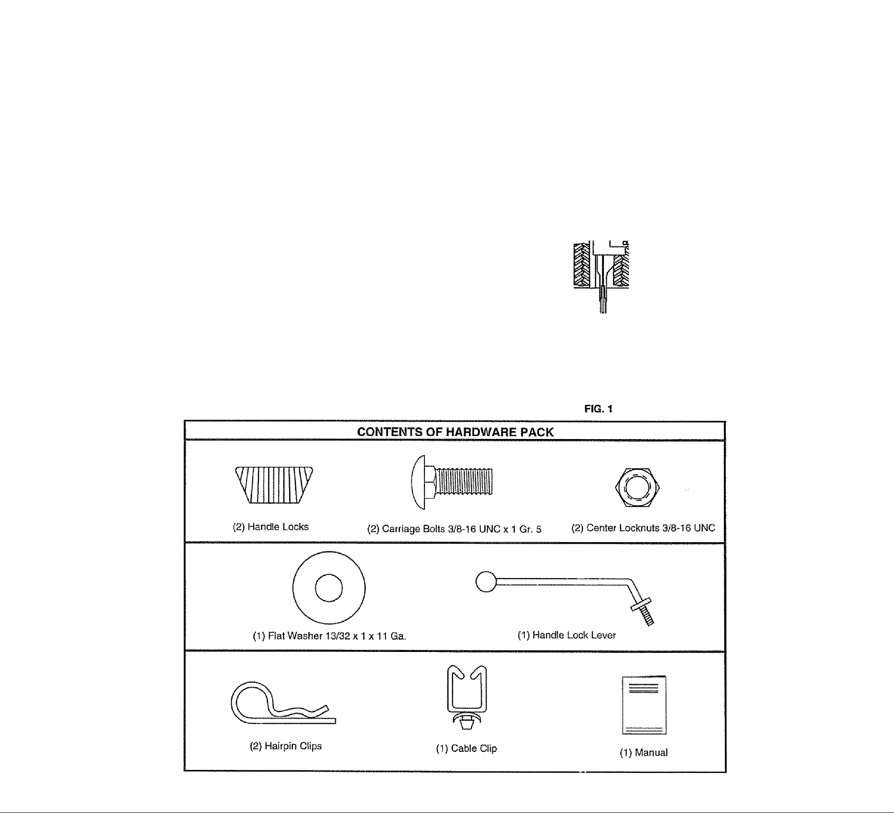
ASSEMBLY
Your new tiller has been assembled at the factory with exception of those parts left unassembled for shipping purposes. To
ensure safe and proper operation of your tiller ail parts and hardware you assemble must be tightened securely. Use the
correct tools as necessary to insure proper tightness.
TOOLS REQUIRED FOR ASSEMBLY
A socket wrench set will make assembly easier. Standard
wrench sizes are listed.
(1) Utility knife
(1) Wire cutter
{1) Screwdriver
(1) Tire pressure gauge
(1) Pair of pliers
{1) 9/16" wrench
OPERATOR’S POSITION {See Fig. 1)
When right or left hand is mentioned in this manual, it
means when you are in the operating position (standing
behind tiller handies).
FRONT
cO
L.EFT
7^
OPERATOR’S
posmoN
RiGHT
Page 7

ASSEMBLY
UNPACKING CARTON {See Fig. 2)
CAUTION: Be careful of exposed
staples when handling or disposing of
cartoning material.
IMPORTANT: WHEN UNPACKING AND ASSEMBLING
TILLER, BE CAREFUL NOT TO STRETCH OR KiNK
CABLES-
■ While holding handle assembly, cut cable ties securing
handte assembly to top frame and depth stake. Let
handle assembly rest on tiller.
" Remove top frame of carton.
» Slowly ease handle assembly up and place on top of
carton,
» Cut down right hand front and right hand rear corners
of carton, lay side carton wall down.
* Remove packing material from handle assembly
» Separate shift rod from handte assembly.
INSTALL HANDLE {See Figs. 3, 4, and 5)
• Insert one handle lock (with teeth facing outward) in
gearcase notch. (Apply grease on smooth side of
handte lock to aid In keeping lock in place until handte
assembly is lowered into position.)
Grasp handte assembly. Hold in "up” position. Be sure
handle lock remains in gearcase notch. Slide handte
assembly into position.
Insert front carriage bolt with care, since space for
installation is limited.
Lower the handle assembly. Tighten locknuts on bolts
so handle moves with some resistance.
Place flat washer on threaded end of handle lock lever.
Insert handle lock lever through handle base and
gearcase. Screw in handte lock lever just enough to
hold lever in place.
Insert second handle lock (with teeth inward) In the slot
of the handle base (just inside of washer).
With handle assembly in lowest position, securely
tighten handle lock lever by rotating clockwise. Leav
ing handle assembly in lowest position will make it
easier to remove tiller from carton.
Page 8

ASSEMBLY
CONNECT SHIFT ROD (See Fig. 6)
• insert end of shift rod farthest from bend into hole of
shift lever indicator,
• insert hairpin clip through hole of shift rod to secure.
» insert other end of shift rod into hole in shift iever.
" insert second hairpin dip through hole of shift rod.
ATTACH THIS END
TO SHIFT LEVER
INDICATOR
SHIFT
ROD
HAIRPIN
CUP
ATTACH THIS
END TO SHIFT
LEVER
SHIFT ROD
SHIFT
LEVER
INDICATOR
REMOVE TILLER FROM CRATE
* Make sure shift lever indicator is in “N" (neutral) posi
tion (See Fig. 6)
» Tilt tiller forward by lifting handle. Separate cardboard
cover from leveling shield,
» Rotate tiiler handle to the right and puli tiller out of
carton.
INSERT CABLE CLIP (See Fig. 7)
* Insert plastic cable dip into hole on the back of handle
column,. Push cables Into clip.
SHIFT LEVER
SHIFT ROD
CHECK TIRE PRESSURE
The tires on your unit were overinllated at the factory for
shipping purposes. Correct and equal tire pressure is
important for best tilling performance.
» Reduce tire pressure to 20 PSl
HANDLE HEIGHT
» Handle height may be adjusted to better suit operator.
(See ‘TO ADJUST HANDLE HEIGHT’ in the Service
and Adjustments section of this manual).
D
HAIRPIN CUP
FIG. 6
Page 9

OPERATION
KNOW YOUR TILLER
READ THIS OWNER'S MANUAL AND SAFETY RULES BEFORE OPERATING YOUR TILLER.
Compare the illustrations with your tiller to familiarize yourself with the location of various controls and adjustments. Save
this manual for future reference.
MEETS ANSI SAFETY REQUIREMENTS
Our tiilers conform to the safety standards of the American National Standards Institute,
CHOKE CONTROL - Used when starting a cold engine.
DEPTH STAKE - Controls depth at which tiller will dig.
DEPTH STAKE - Controls forward speed and the depth at
which the tiller will dig.
DEPTH STAKE PIVOT ’ Controis pivoting action of depth
slake.,
DRIVE CONTROL BAR - Used to engage tines,
FORWARD TINE CONTROL Engages tines in forward
direction,
REVERSE TINE CONTROL - Engages tines in reverse
direction.
CULTIVATING SHIELDS - Engages tines
{ QHIPI n - \ caUAÍQ HliaH cirtll
V I»» l«*ll 11 Iw i» I«/ I-T-C» V w 1LMIC5LJ Ov'iIh.
OUTER SIDE SHIELD - Adjustable to protect smalt plants
from being buried.
RECOIL STARTER HANDLE - Used to start the engine.
SHIFT LEVER - Used to shift transmission gears.
SHIFT LEVER INDICATOR - Shows which gear the tranS'
mission is in.
THROTTLE CONTROL - Controls engine speed
STOP SWITCH - Used to stop engine. Must be in "ON”
position when starting engine.
Page 10

OPERATION
The operation of any tiller can result in foreign objects thrown into the eyes, which can
result in severe eye damage. Always wear safety glasses or eye shields before starting
your tiller and while tilling. We recommend a wide vision safety mask over the spectacles
or standard safety glasses.
HOW TO USE YOUR TILLER
Know how to operate all controls before adding fuel and
oil or attempting to start engine.
STOPPING (See Fig. 9)
TINES AND DRIVE
» Release drive control bar to stop movement.
" Move shift lever to "N" (neutral) position.
ENGINE
" Move throttle control to "STOP” position.
“ Never use choke to stop engine.
TINE OPERATION - WITH WHEEL DRIVE
“ Always release drive control bar before moving shift
lever into another position.
» Tine movemerit ts achieved by moving shift lever to “T"
(till) position and engaging drive control bar.
DEPTH STAKE (See Fig. 10)
The depth stake can be raised or lowered to allow you more
versatile tilling and cultivating, or to more easily transport
your tiller
TILLING (See Fig. 11)
. Release depth stake pin. Pull the depth stake up for
increased tilling depth. Place depth stake pin in hole of
depth stake to lock in position.
" Place shift lever indicator in 'T' position.
" Hold the drive control bar against the handle to start
tilling movement. Tines and wheels will both turn,
“ Move throttle control to “FAST’ position for deep tilling.
To cultivate, throttle control can be set at any desired
speed, depending on how fast or slow you wish to
cultivate,.
IMPORTANT: ALWAYS RELEASE DRIVE CONTROL BAR
BEFORE MOVING SHIFT LEVER INTO ANOTHER
POSITION
FORWARD-WHEELSONLY/TINES STOPPED
“ Release drive control bar and move shift lever indicator
to "P’ (forward) position. Engage drive control bar and
tiller will move forward.
reverse - WHEELS ONLY/TINES STOPPED
DO NOT STAND DIRECTLY BEHIND TILLER,
Release the drive control bar.
Move throttle control to “SLOW" position.
Move shift lever indicator to “R” (reverse) position.
Hold drive control bar against the handle to start tiller
movement.
10
Page 11

OPERATION
TURNING
« Release the drive control bar.
« Move throttle control to "SLOW” position.
" Place shift lever indicator in “P (forward) position.
Tines will not turn,
■> Lift handle to raise tines out of ground.
» Swing the handle in the opposite direction you wish to
turn, being careful to keep feet and legs away from
tines.
• When you have completed your turn-around, release
thedrivecontrolbarandlowerhandle- Place shift lever
in “T" (till) position and move throttle control to desired
speed. To begin tilling, hold drive control bar against
the handie.
OUTER SIDE SHIELDS (See Fig. 11)
The front edges of the outer side shields are slotted so that
the shields can be raised for deep tilling and lowered for
shallow tilling to protect small plants from being burled.
Loosen nut “A" in slot and nut “B". Move shield to desired
position (both sides). Retighten nuts.
TO TRANSPORT
CAUTION: Before lifting or transport
ing, allow tiller engine and muffler to
cool. Disconnect spark plug wire. Drain
gasoline from fuel tank.
AROUND THE YARD
» Release the depth stake pin. Move the depth stake
down to the top hole for transporting the tiller. Place
depth stake pin in hole of depth stake to lock in position.
This prevents tines from scuffing the ground.
® Place shift lever indicator in “F" (forward) position for
transporfing.
» Hold the drive control bar against the handie to start
tiller movement. Tines will not turn,,
• Move throttle control to desired speed,
AROUND TOWN
» Disconnect spark plug wire.
» Drain fuel tank.
• Transport in upright position to prevent olì leakage.
BEFORE STARTING ENGINE
IMPORTANT: BH VERY CAREFUL NOT TO ALLOW DIRT
TO ENTER THE ENGINE WHEN CHECKING OR ADDING
OIL OR FUEL. USE CLEAN OIL AND FUEL AND STORE
IN APPROVED, GLEAN, COVERED CONTAINERS USE
CLEAN FILL FUNNELS,
CHECK ENGINE OIL LEVEL (See Fig. 12)
o The engine in your unit has been shipped, from the
factory, already filled with SAE 30 summer weight oil
• With engine level, clean area around oil filler plug and
remove plug.
Engine oil should be to point of overflowing. For
approximate capacity see “PRODUCT SPECIFICA
TIONS" on page 3 of this manual. All oil must meet
A.P.I. Service Classification SF or SG.
For cold weather operation you should change oil for
easier starting (See oil viscosity chart in the Customer
Responsibilities section of this manual).
To change engine oil, see the Customer Responsibili
ties section in this manuai-
ADD GASOLINE
» Fill fuel tank. Use fresh, clean, regular unleaded
gasoline. (Use of leaded gasoline will increase carbon
and lead oxide deposits and reduce valve life.
IMPORTANT: WHEN OPERATING IN TEMPERATURES
BELOW32“F(0"C), USE FRESH, CLEAN, WINTER GRADE
GASOLINE TO HELP INSURE GOOD COLD WEATHER
STARTING.
WARNING: Experience indicates that alcohol blended
fuels (called gasohol or using ethanol or methanol) can
attract moisture which leads to separation and formation of
acids during storage. Acidic gas can damage the fuel
system of an engine while in storage. To avoid engine
problems, the fuel system should be emptied before stor
age of 30 days or longer. Drain the gas tank, start the
engine and let it run until the fuel lines and carburetor are
empty. Use fresh fuel next season. See Storage section
of this manual for additional information. Never use engine
or carburetor cleaner products in thefueltankor permanent
damage may occur.
CAUTION: Fill to within 1/2 inch of top
of fuel tank to prevent spills and to
allow for fuel expansion. If gasoline Is
accidentally spilled, move machine
away from area of spill. Avoid creating
any source of ignition until gasoline
vapors have disappeared.
Do not overfill. Wipe off any spilled oil
or fuel. Do not store, spill or use gaso-
ill • i 1 virCS I dl I Lr I 11 c« I i i Ih# 1»
11
Page 12

OPERATION
TO START ENGINE (See Fig, 17)
., CAUTION: Keep tine control in "OFF”
4(" position when starting engine.
* Make sure spark plug wire is properly connected and
access cover is completely closed to create propet
seal„
» Place throttle control in "FAST' positiort.
» Turn fuel shut-off valve to "ON" position.
« Push stop switch to "ON” position.
« With engine fully choked, grasp recoil starter handle
with one hand and grasp tiller handle with other hand.
Puli rope out siowly until engine reaches start of com
pression cycle (rope will pull slightly harder at this
point).
« Puil recoil starter handle quickly. Do not let starter
handie snap back against starter. Repeat if necessary
in half choked position.
* When engine starts, slowly move choke control to
"RUN" position as engine warms up,.
NOTE; A warm engine requires less choking to start.
' Move throttle control to desired running position.
“ Allow engine to warm up for a few minutes before
engaging tines.
NOTE: If at a high altitude (3000 feet) or in cold tempera
tures (below 32“F), the carburetor fuel mixture may need to
be adjusted for best engine performance. See “TO AD
JUST CARBURETOR" in the Service and Adjustments
section of this manual.
NOTE: If engine does not start, see troubleshooting points.
Soil conditions are important for proper tilling. Tines wili
not readily penetrate dry, hard soil which may contrib
ute to excessive bounce and difficult handling of your
tiller. Hard soil should be moistened before tilling;
however, extremely wet soil will “bali-up” or clump
during tilling. Wait until the soil is less wet in order to
achieve the best results. When tilling in the fail, remove
vines and long grass to prevent them from wrapping
around the fine shaft and slowing your tilling operation.
Do not lean on handie. This takes weight off the wheels
and reduces traction. To get through a really tough
section of sod or hard ground, apply upward pressure
on handie or lower the depth stake.
CULTIVATING
Cultivating is destroying the weeds between rows to pre
vent them from robbing nourishment and moisture from the
plants. At the same time, breaking up the upper layer of soil
crust will help retain moisture in the soil. Best digging depth
is 1" to 3" Lower the outer side shields to protect small
plants from being buried.
• Cultivate up and down the rows at a speed which will
albw tines to uproot weeds and leave the ground in
rough condition, promoting no further growth of weeds
and grass (See Fig. 15)
CAUTION: Until you are accustomed to
handling your tiller, start actual field
use with throttle in slow position (mid
way between “FAST" and “IDLE").
Tilling Is digging into, turning over, and breaking up
packed soil before planting. Loose, unpacked soli
helps root growth. Best titling depth is 4“ to 6*'. A tiller
will also clear the soli of unwanted vegetation. The
decomposition of this vegetable matter enriches the
soil. Depending on the climate (ralnfaii and wind), it
may be advisable to till the soil at the end of the growing
season to further condition the soil.
For easier handling of your tiiier, leave about 8 inches
of untllled soil between the first and secohd tilling
passes. The third pass wili be between the first and
second (See Fig. 14).
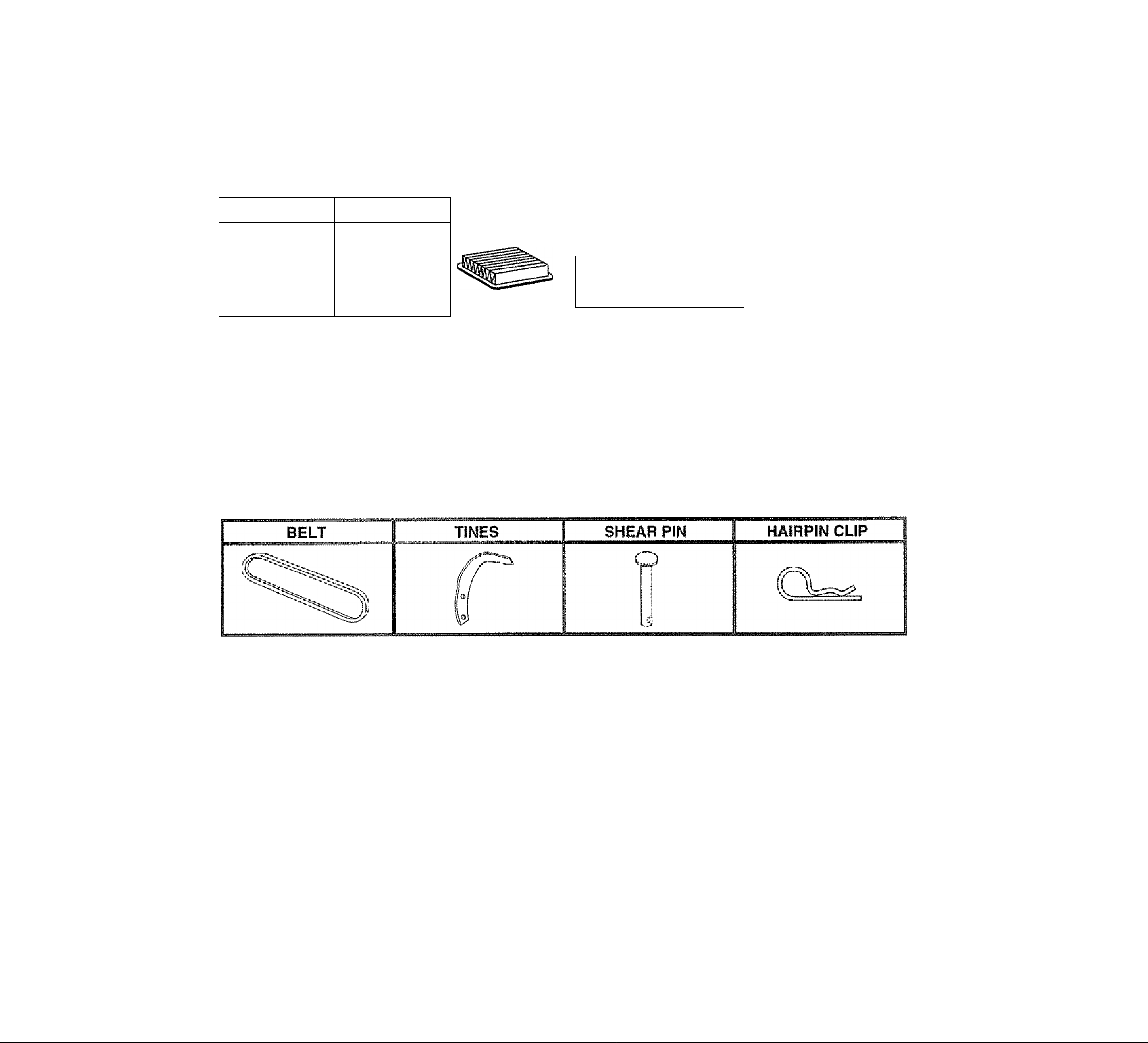
TINE SHEAR PINS
The tine assemblies on your tiller are secured to the tine
shaft with shear pins (See ‘TINE REPLACEMENT” in the
Service and Adjustments section of this manual).
If the tiller is unusualiy overioaded or Jammed, the shear
pins are designed to break before internal damage occurs
to the transmission,
» If shear pln(s) break, replace only with those shown in
the Repair Parts section of this manual.
12
Page 13

CUSTOMER RESPOiSlSiBlLmES
MAINTENANCE
SCHEDULE
FILL IN DATES
AS YOU COMPLETE
REGULAR SERVICE
Check Engine Oil Level ✓
Change Engine Oil
Oil Pivot Points
Inspect Spark Arrester / Muffler
Inspect Air Screen
Glean or Replace Air Cleaner Cartridge
Glean Engine Cylinder Fins
Replace Spark Plug
1 - Change more often when oparaling under a heavy load or in high ambienf temperalures
✓
✓
✓
✓
✓
✓
i4
✓
8/
2 - Service more often when operating in dirty or dusty conditions
GENERAL RECOMMENDATIONS
The warranty on this tiller does not cover items that have
been subjected to operator abuse or negligence. To
receive full value from the warranty, the operator must
maintain tiller as instructed in this manual.
Some adjustments will need to be made periodically to
properiy maintain your tiller.
Ail adjustments in the Service and Adjustments section of
this manual should be checked at least once each
season.
' Once a year you shouid replace the spark plug, clean
or replace air filter, and check tines and belts for wear.
A new spark plug and clean air filter assure proper airfuel mixture and help your engine run better and last
longer
—
LUBRICATION CHART
* ymEJATTI Si
CONTROL
BEFORE EACH USE
• Check engine oil level.
» Check tine operation,
• Check for loose fasteners
LUBRICATION
Keep unit well lubricated (See "LUBRICATION CHART”).
' SAE 30 OR 10W-30 MOTOR OIL
■* REFER TO CUSTOMER RESPONSIBILITIES “ENOINE" SECTION
13
Page 14

CySTOPER RESPOMSIBILITIES
Disconnect spark plug wire before performing any maintenance (except carburetor adjustment) to prevent
accidental starting of engine.
Prevent firesi Keep the engine free of grass, leaves, spilled oil, orfuei. Remove fuel from tank before tipping
unit for maintenance. Clean muffler area of all grass, dirt, and debris.
Do not touch hot muffler or cylinder fins as contact may cause burns.
ENGINE
LUBRICATION
Use only high quality detergent oil rated with API service
Glassification SF orSG. Select the oil’s SAE viscosity grade
________
•p
-ao"
'’C -30“
TEMPERATURE RANGE ANTICIPATED BEFORE NEXT Oii CHANGE
NOTE: Although mu It!-viscosity oils (5W-30,10W-30, etc,)
improve starting in cold weather, these multi-viscosity oils
will resuit in Increased oii consumption when used above
32°F (O^’C). Check yout engine oil level more frequently to
avoid possible engine damage from running low on oil.
Change the oii after the first two hours of operation and
every 25 hours thereafter or at least once a year if the tiller
is not used for 25 hours in one year.
Check the crankcase oil level before starting the engine
and after each five (5) hours of continuous use. Add SAE
30 motor oil or equivalent. Tighten oil filler plug securely
each time you check the oil level.
TO CHANGE ENGINE OIL (See Figs. 16 and 17)
Determine temperature range expected before oil change.
All oil must meet API service classification SF or SG
= Be sure tiller is on level surface.
* Oil will drain more freely when warm.
« Use a funnel to prevent oil spill on tiller, and catch oil in
a suitable container.
» Remove drain plug.
“ Tip tiller forward to drain oil.
» After oil has drained completely, replace oil drain plug
and tighten securely,
» Remove oii filler plug. Be careful not to allow dirt to
enter the engine.
» Refill engine with oil. See “CHECK ENGINE OIL
LEVEL” in the Operation section of this manual.
--
.......
‘ ' temperature
SAE VISCOSITY GRADES
:V •
r-iV/STi
...
0" 30* 3a* 4D"
« l 1 j.—. - , I I , I .....................................................
20" *10‘ 0“ 10" 20" 30” 40"
■
Tí
60'’ 80° 100^
FiG. 16
.....
............
Service alt cleaner more often under dusty conditions.
« Loosen air cleaner cover screws. Remove cover and
air cleaner assembly from base.
« Remove air cleaner asssembly from inside cover and
disassemble.
TO SERVICE PRE-CLEANER
« Wash it in liquid detergent and water.
« Squeeze it dry in a clean cloth.
“ Saturate it in engine oil. Wrap it in dean, absorbent
cloth and squeeze to remove excess oil.
TO SERVICE CARTRIDGE
" Gently tap the flat side of the paper cartridge to dis
lodge dirt. Do not wash the paper cartridge or use
pressurized air, as this will damage the cartridge.
Replace a dirty, bent, or damaged cartridge.
• Re-assemble retainer on pre-cleaner and cartridge
^creen side of pre-cleaner toward cartridge pleats).
Place assembly into cover.
« Insert tabs on cover into slots in base and tighten cover
screws securely.
CAUTION: Petroleum solvents, such
as kerosene, are not to be used to clean
\
iniriiniiitiTiiaii»*
cartridge. They may cause deteriora
tion of the cartridge. Do not oii car
tridge. Do not use pressurized air to
clean or dry cartridge.
FIG. 18
COOLING SYSTEM (See Fig. 19)
Your engine is air cooled. For proper engine performance
and long life keep your engine clean,
» Clean air screen frequently using a stiff-bristled brush.
® Remove blower housing and clean as necessary.
® Keep cylinder fins free of dirt and chaff.
Your engine will not run properly using a dirty air filter.
Clean the foam pre-cleaner after every 25 hours of opera
tion or every season. Service paper cartridge every 100
hours of operation orevery season, whichever occurs first
14
FIG. 19
BLOWER
HOUSING
AIR
SCREEN
Page 15

CUSTOMER RESPONSIBILITIES
MUFFLER
Do not operate tiller without muffler Do not tamper with
exhaust system. Damaged mufflers or spark arresters
could create a fire hazard. Inspect periodically and replace
if necessary, if your engine is equipped with a spark
arrester screen assembly, remove every 50 hours for
cleaning and inspection. Replace if damaged.
SPARK PLUG
Replace spark plugs at the beginning of each tilling season
or after every 50 hours of use, whichevercomesfirst. Spark
plug type and gap setting is shown in “PRODUCT SPECI
FICATIONS” on page 3 of this manuaS
SERVICE AND ADJUSTMENTS
CAUTION: Disconnect spark plug wire from spark plug and place wire where it cannot come into
A
TILLER
TO ADJUST HANDLE HEIGHT (See Fig. 20)
Select handle height best suited for your tilling conditions.
Handle height will be different when tiller digs into soil
» First loosen handle lock lever,
" Handle can be positioned at different settings between
"HIGH" and “LOW” positions,
“ Retighten handle lock lever securely after adjusting.
contact with plug.
TRANSMISSION
Yourtransmission is sealed and will only require lubrication
if serviced.
CLEANING
® Clean engine, wheels, finish, etc. at ail foreign matter.
» Keep finished surfaces and wheels free of alt gasoline,
oil, etc.
' Protect painted surfaces with automotive type wax.
We do not recommend using a garden hose to clean your
unit unless the muffler, air filter and carburetor are covered
to keepwaterout. Waterin engine can result inashortened
engine life.
TO REMOVE WHEEL (See Fig. 21)
» Place blocks under transmission to keep tiller from
tipping,
« Remove outer side shield by removing nuts “A” and “B".
' Remove inner side shield by removing nuts ”C" and
“0”.
» Remove hairpin clip and clevis pin from wheel,
® Remove wheel and tire,
* Repair tire and reassemble.
CAUTION: When mounting tires, un
less beads are seated, overinflation
vi-i can cause an explosion.
« Maintain 20 pounds of tire pressure. If tire pressures
are not equal, tiller will pull to one side.
« Keep tires free of gasoline or oil which can damage
rubber
15
Page 16

SERVICE AND ADJUSTMENTS
TO REMOVE BELT GUARD (See Fig. 22)
■* Remove L.H, inner and outer side shields (See "TO
REMOVE WHEEL" in this section of this manual).
« Remove hairpin dip and clevis pin from left wheel. Puii
wheel out from tiiier about 1 inch,
" Remove two (2) cap nuts and washers from side of belt
guard.
• Remove hex nut and washer from bottom of belt guard
(located behind wheel).
" Puii belt guard out and away from unit,
“ Replace belt guard by reversing above procedure.
TO REPLACE GROUND DRIVE BELT (See
Figs. 22 and 23)
® Remove belt guard. (See‘TO REMOVE BELT GUARD"
in this section of this manual).
" Loosen belt guides "A" and *'B" and also nuts “C” and
* Remove oid belt by slipping from engine puiley first.
“ Place new belt in groove of transmission pulley and
into engine pulley . BELT MUST BE IN GROOVE ON
TOP OF IDLER PULLEY. NOTE POSITION OF BELT
f^i
TO
* Tighten belt guides "A" and "B" and nuts “C" and “D”.
" Check belt adjustment as described beiow,
“ Replace belt guard.
= Reposition wheel and replace clevis pin and hairpin
ciip.
“ Replace inner and outer side shields.
GROUND DRIVE BELT ADJUSTMENT (See
Fig. 23)
For proper belt tension, the extension spring should have
about 5/8 inch stretch when drive control bar is in "EN
GAGED” position. This tension can be attained as follows:
® Loosen cable ciip screw securing the drive control
cable,
® Slide cable forward for less tension and rearward for
more tension until about 5/8 inch stretch is obtained
while the drive control bar is engaged.
® Tighten cable dip screw securely.
NUT"C"
ENGINE
PULLEY
IDLER
PULLEY
TRANSMISSiON
PULLEY
BELT
GUIDE “A”
F!G. 23
. CABLE CLIP
SCHEW
DRIVE
CONTROL
CABLE
16
Page 17

SERVICE AND ADJUSTMENTS
TINE REPLACEMENT (See Figs. 24,25 and 28)
CAUTION: Tines are sharp. Wear
gloves or other protection when han
A
A badly worn tine causes your tiller to work harder and dig
more shailow. Most important, worn tines cannot chop and
shred organic matter as effectively nor bury it as deeply as
good tines. A tine this worn needs to be replaced.
dling tines.
To maintain the superb tilling performance of this
machine the tines should be checked for sharpness,
wear, and bending, particularly the tines which are next
to the transmission. If the gap between the tines
exceeds 3-1/2 inches they should be replaced or
straightened as necessary.
New tines should be assembled as shown in Fig. 26.
Sharpened tine edges will rotate rearward from above.
17
Page 18

SERVICE AND ADJUSTMENTS
ENGINE
TO ADJUST THROTTLE CONTROL CABLE
(See Fig. 27)
» Loosen cable clamp screw to allow cable to move.
® Move throttle control lever on upper handle to "FAST"
position.
« Pull throttle cable out to end of travel
« Hold cable in this position and tighten clamp screw
securely.
TO ADJUST CARBURETOR (See Fig. 28)
The carburetar has a high speed jet and has been preset at
the factory arid adjustment should not be necessary How
ever, minor adjustments may be required to compensate
for differences in fuel, temperature, altitude or toad. If the
carburetor does need adjustment, proceed as follows.
In general, turning the idle needle valve in (clockwise)
decreases the supply of fuel to the engine giving a leaner
fuel/air mixture. Turning the needle valve out (counter
clockwise) increases the supply of fuel to the engine giving
a richer fuel/air mixture,
IMPORTANT: DAMAGE TO THE NEEDLES AND THE
SEATS IN CARBURETOR MAY RESULT IF SCREWS ARE
TURNED IN TOO TIGHT.
PRELflVIlNARY SETTING
* Air cleaner assembly must be assembled to the carbu
retor when making carburetor adjustments.
• Be sure the throttle control cable is adjusted properly
(see above).
» With engine off, turn idle needle valve in (clockwise)
closing it finger tight and then turrr valve out (counter
clockwise) 1-1/2 turns.
•
FINAL SETTING
® Start engine and aliow to warm for five minutes. Make
final adjustments with engine running at idie and drive
control bar in "DISENGAGED” position.
" With throttle control lever in "SLOW" position, turn idle
needle valve in (clockwise) until engine begins to die
then turn out (counterclockwise) until engine runs
roug h, Tu rn valve to a point midway between those two
positions,
IDLE RPM ADJUSTMENT
“ To adjust idle RPM, rotate throttle linkage counter
clockwise and hold against stop while adjusting idle
speed adjusting screw to obtain 1750 RPM. Release
throttle linkage.
ACCELERATION TEST
“ Move throttle control lever from “SLOW" to "FAST”
position. If engine hesitates or dies, turn needle valve
out (courjterclockwise) 1/8 turn Repeat test and
continue to adjust, if necessary, until engine acceierates smoothly.
High speed stop is factory adjusted. Do not adjust or
danrage may result.
IMPORTANT; NEVER TAMPER WITH THE ENGINE
GOVERNOR, WHICH IS FACTORY SET FOR PROPER
ENGINE SPEED OVERSPEEDING THE ENGINE ABOVE
THE FACTORY HIGH SPEED SETTING CAN BE
DANGEROUS. IF YOU THINK THE ENGINE-GOVERNED
HIGH SPEED NEEDS ADJUSTING, CONTACT YOUR
NEAREST AUTHORIZED SERVICE CENTER/
DEPARTMENT, WHICH HAS THE PROPER EQUIPMENT
AND EXPERIENCE TO MAKE ANY NECESSARY
ADJUSTMENTS.
FIG. 28
18
Page 19

STORAGE
Immediately prepare your tiller for storage at the end of the
season or if the unît will not be used for 30 days or more.
CAUTION: Never store the tiller with
gasoline in the tank inside a buiiding
where fumes may reach an open flame
or spark. Allow the engine to cool
before storing in any enclosure.
TILLER
“ Clean entire tiller (See “CLEANING” in the Customer
Responsibilities section of this manual).
“ Inspect and replace belts, if necessary (See beit re
placement instructions in the Service and Adjustments
section of this manuai).
» Lubricate as shown in the Customer Responsibilities
section of this manual
• Be sure that all nutSi bolts and screws are securely
fastened. Inspect moving parts for damage, breakage
and wear. Replace if necessary.
" Touch up all rusted or chipped paint surfaces; sand
lightly before painting.
ENGINE
FUEL SYSTEM
IMPORTANT: IT IS IMPORTANT TO PREVENT GUM
DEPOSITS FROM FORMING IN ESSENTIAL FUEL
SYSTEM PARTS SUCH AS THE CARBURETOR, FUEL
FILTER, FUEL HOSE, OR TANK DURiNG STORAGE.
ALSO, EXPERIENCE INDICATES THAT ALCOHOL
BLENDED FUELS (CALLED GASOHOL OR USiNG
ETHANOL OR METHANOL) CAN ATTRACT MOISTURE
WHICH LEADS TO SEPARATION AND FORMATION OF
STORAGE. ACIDIC GAS CAN DAMAGE
THE FUEL SYSTEM OF AN ENGINE WHILE IN STORAGE.
" Drain the fuel tank,
• Start the engine and let it run until the fuel lines and
carburetor are empty.
•> Never use engine or carburetor cleaner products in the
fuel tank or permanent damage may occur.
• Use fresh fuel next season,
NOTE: Fuel stabilizer is an acceptable alternative in
minimizing the formation of fuel gum deposits during stor
age. Add stabilizer to gasoiine in fuel tank or storage
container. Always foiiow the mix ratio found on stabilizer
container. Run engine at least 10 minutes after adding
stabilizer to allow the stabilizer to reach the carburetor. Do
not drain the gas tank and carburetor if using fuel stabilizer.
ENGINE OIL
Drain oil (with engine warm) and replace with clean oii.
(See “ENGINE” in the Customer Responsibilities section of
this manual),
CYLINDERS
® Remove spark plug.
* Pour 1 ounce (29 ml) of oil through spark plug hole into
cylinder,
« Pull starter handle slowly several times to distribute oil.
® Replace with new spark plug.
OTHER
“ Do not Store gasoiine from one season to another.
• Replace your gasoline can if your can starts to rust.
Rust and/or dirt in your gasoline will cause problems,
“ If possible, store your unit indoors and cover it to give
protection from dust and dirt.
® Cover your unit with a suitable protective cover that
does not retain moisture. Do not use piastic. Plastic
cannot breathe which allows condensation to form and
will cause your unit to rust
IMPORTANT: NEVER COVER TILLER WHILE ENGINE
AND EXHAUST AREAS ARE STILL WARM
19
Page 20

TROÖBLESHOOTIiSiG POIMTS
PROBLEM
Will not start
Hard to start
Loss of power
CAUSE
1. Out of fuel
2 Engine not “CHOKEO" properly,
3, Engine fJooded4- Dirty air cleaner
5 Water in fuel.
6, Clogged fuel tank
7 Loose spark plug wire
a. Bad spark plug or irrtproper gap
9. Carburetor out of adjustment
10. Oil soaked air filter
1, Throttle control not set properly.
2 Dirty air claaner.
3 Bad spark plug or improper gap
4 Stale Of dirty fuel
5. Loose spark plug wire
6, Carburetor out of adjustment.
Engine is overloaded.
1,
Dirty air cleaner.
2
Low oil levBl/dtrty oil
3,
Faulty spark plug
4
Oil in fuel.
5,
Stale or dirty fuel
6
Water in fuel-
7,
Clogged fuei tank
В
Spark plug wire loose
9
Dirty engine air screen
10
Dirty/cloggad muffiet.
11
Carburetor out of adjustment
12
Roof compression.
13
CORRECTiON
1Fill fuel tank.
2. See 'TO START ENGINE” in Operation section
3. Wait several minutes before attempting to start
4. Clean or replace air cleaner cartridge.
5. Drain fuel tank and carburetor, and refill tank with fresh
gasoline,
6. Remove fuel lank and dean,
7. Make sure spark plug wire is seated properly on plug.
8. Replace spark plug or adjust gap.
9. Make necessary adjustments.
10 Replace air filter
1. Place throttle control in "FAST“ position.
2. Clean or raplaos air cleaner cartridge,
3 Replace spark plug or adjust gap
4, Drain fuel tank and refill with fresh gasoline.
5, Make sure spark plug wire is seated properly on plug
6, Make necessary adjustments.
Set depth stake for shallower tilling
1.
Clean Of replace air cleaner cartridge
2-
Check oil Isvei/change oil,
3
Clean and regap or change spark plug.
4.
Orain and clean fuel tank and reffll, and clean carburetor.
5.
Drain fuel tank and reil with fresh gasoline
6-
Drain fuel lank and carburetor, and refill tank with fresh
gasoline
Remove fuel tank atrd clean
В
Connect and tighten spark plug wire.
9
Clean engine air screen
10
Ctean/repiace muffler.
11.
Maks necessary adjustments.
12
Contact an authorized service centar/department
13,
Engine overheats
Excessive bounce/
difficult handling
Soil balls up or clumps
Engine runs but tiller
won’t move
Engine runs but labors
when tilling
Tines will not rotate
1. Low oil iBveS/dirty oil
2. Dirty engine air screen.
3. Dirty engine.
4 Partially plugged muffler
5 Improper carburetor adjustment.
1. Ground too dry and hard
1 Ground too wet.
1, Drive control bar is not engaged
2 V-belt not correctly adjusted
3, V-belt is off pulteyjs).
1. Tilling too deep,
2. Throttle control not properly adjusted.
3 Carburetor out ol adjustment,
1, Shear ptn/sj brakars.
1Check oil leval/chartge oil
2. Clean engine air screen.
3. Clean cylinder fins, air screen, and muffiet area
4. Remove and clean muffler,
5. Adjust carburetor to richer position
1 Moisten ground or wait tot more favorable soil
conditions
1 Wait for more favorable soil conditions.
1 Engage drive control
2. i nspecl/adjust V-belt
3 Inspect V-belt
1. Set depth stake for shallower tilling
2. Check throttle control sattlng
3. Make necessary adjustments
1, Replace shear pln{s).
20
Vr
 Loading...