

Craftsman 917295450 Owner’s Manual
MODEL NO.
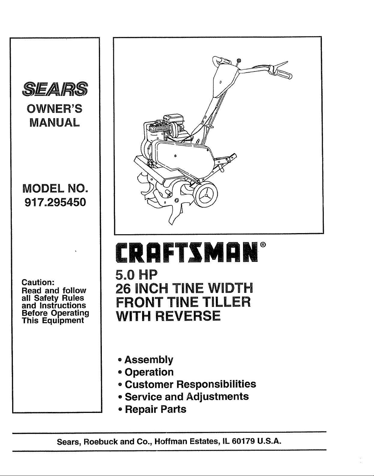
917.295450
Caution:
Read and follow
all Safety Rules
and Instructions
Before Operating
This Eqmpment
MDM°
5.0 HP
26 H TiNE WIDTH
FRONTTi E TILLER
WITH E
=Assembly
=Operation
=Customer Responsibilities
° Service and Adjustments
° Repair Parts
i
Sears, Roebuck and Co., Hoffman Estates, IL 60179 U.S.A.
Safe Operation Practices for Walk-Behind Powered Rotary Tillers
SAFETY RULES
TRAINING
• Read the Owner's Manual carefully° Be thoroughly
familiar with the controls and the proper use of the
equipment. Know how to stopthe unit and disengage
the controlsquickly_
• Never allow childrento operate the equipment. Never
allow adults to operate the equipment withoutproper
instruction..
° Keepthe area ofoperation clear of all persons, particu-
larly small children, and pets.
PREPARATION
• Thoroughly inspect the area where the equipment isto
be used and remove all foreign objects.
• Disengage all clutches and shift into neutral before
starting the engine (motor).
° Do not operate the equipment without wearing ad-
equate outer garments. Wear footwear that will im-
provefooting on slippery surfaces_
° Handle fuel with care; it is highly flammable_
° Use an approved fuel container.
° Never add fuel to a running engine or hot engine.
• Fill fuel tank outdoors with extreme care_Never fill
fuel tank indoors..
• Replace gasoline cap securely and clean up spilled
fue! before restarting.
° Use extension cords and receptacles as specified by
the manufacturer for alt units with electric ddve motors
or electric starting motors..
• Never attempt to make any adjustments while the
engine (motor) is running (except where specifically
recommended by manufacturer)°
OPERATION
• Do not put hands or feet near or under rotating parts..
° Exercise extreme caution when operating on or cross-
ing gravel drives, walks, or roads. Stay alert for hidden
hazards or traffic.. Do not carry passengers°
° After striking a foreign object, stop the engine (motor);
remove the wire from the spark plug, thoroughly in-
spect the tiller for anydamage, and repair'the damage
before restarting and operating the tiller'.
• Exercise caution to avoid slipping or falling,
• If the unitshould start to vibrate abnormally, stop the
engine (motor) and check immediately for the cause..
Vibration is generally a warning of trouble.
• Stop the engine (motor) when leaving the operating
position.
° Take all possible precautions when leaving the ma-
chine unattended. Disengage the tines, shift into
neutral, and stop the engine.
• Before cleaning, repairing, or inspecting,shut off the
engine and make certain all moving partshave stopped..
Disconnect the spark plug wire, and keep the wire
away from the plug to prevent accidental starting°
Disconnect the cord on electric motors°
• Do not run the engine indoors; exhaust fumes are
dangerous.
• Never operatethe tiller without proper guards, plates,
or other safety protective devices in place,.
• Keep children and pets away.
• Do not overload the machine capacity by attempting to
till too deep at too fast a rate°
° Never operate the machine at high speeds on slippery
surfaces_ Look behind and use care when backing.
° Never allow bystanders near the unit.,
• Use only attachments and accessories approved by
the manufacturer' of the tiller (such as wheel weights,
counterweights, cabs, and the like).
° Never operate the tillerwithout good visibilityor lighL
° Be careful when tilling in hard ground.. The tines may
catch in the ground and propel the tiller' forward. Ifthis
occurs, let go ofthe handlebars and do not restrain the
machine,,
MAINTENANCE AND STORAGE
° Keep machine, attachments, and accessories in safe
working condition
• Check shear pins, engine mounting bolts, and other
bolts at frequent intervalsfor proper tightness to be
sure the equipment is insafe working condition.
• Neverstore the machine withfuel inthefuel tank inside
a building where ignitionsources are present, such as
hot water and space heaters, clothes dryers, and the
like. Allow the engine to cool before storing in any
enclosure.,
• Always refer to the operator's guide instructions for
important details if the tiller is to be stored for an
extended period.
- IMPORTANT-
CAUTIONS, IMPORTANTS, AND NOTES ARE A MEANS OF ATTRACTING ATTENTION TO IMPORTANT OR CRITICAL
INFORMATION 1NTHIS MANUAL
IMPORTANT: USED TO ALERT YOU THAT THERE IS A
POSSIBILITY OF DAMAGING THIS EQUIPMENT.
NOTE: Gives essential information that will aid you to better
understand, incorporate, or execute a particular set of instruc-
tions,.
A
CAUTION: Look for this symbol to point
out important safety precautions. It
means ---Attention! Become Alert! Your
safety is involved.
2
CONGRATULATIONS on your purchase of a Sears Tiller°
It has been designed, engineered and manufactured to
give you the best possible dependability and performance.,
Should you experience any problems you cannot easily
remedy, please contact your nearest authorized Sears
Service Center/Department.. We have competent, welt-
trained technicians and the proper tools to service or repair
this unit..
Please read and retain this manual° The instructions will
enable you to assemble and maintain your tiller properly.
Always observe the "SAFETY RULES'L
MODEL
NUMBER 917.295450
SERIAL
NUMBER
DATE OF
PURCHASE
THE MODEL AND SERIAL NUMBERS WILL BE
FOUND ON THE MODEL PLATE ATTACHED TO
THE RIGHT HAND ENGINE BRACKET°
YOU SHOULD RECORD BOTH SERIAL NUMBER
AND DATE OF PURCHASE AND KEEP IN A SAFE
PLACE FOR FUTURE REFERENCE°
PRODUCT SPECIFICATIONS
HORSEPOWER: &0 HP
DISPLACEMENT: 12o57cu, in..
GASOLINECAPACITY: 3 Quarts
UnleadedRegular
OIL (API-SF/SG): SAE30 (Above 32°F)
(CAPACITY:20oz.) SAE5W_30(Below32°F)
SPARKPLUG: ChampionRJ19LM
(GAP: ,030") (STD361458)
MAINTENANCE AGREEMENT
A Sears Maintenance Agreement is available on thisprod-
uct, Contact your nearest Sears store for details.
CUSTOMER RESPONSIBILITIES
o Read and observe the safety rules,.
• Followa regular schedule in maintaining, caring for and
using your tiller,
• Follow the instructions under the "Customer
Responsibilities" and "Storage" sections ofthis Owner's
Manual
IMPORTANT: THIS UNIT IS EQUIPPED WITH AN INTERNAL COMBUSTION ENGINE AND SHOULD NOT BE USED ON
OR NEAR ANY UNIMPROVED FOREST-COVERED, BRUSH-COVERED OR GRASS COVERED LAND UNI.ESS THE
ENGINE'S EXHAUST SYSTEM IS EQUIPPED WITH A SPARK ARRESTER MEETING APPLICABLE LOCAL OR STATE
LAWS (IF ANY).. IF A SPARK ARRESTER IS USED, IT SHOULD BE MAINTAINED IN EFFECTIVE WORKING ORDER BY
THE OPERATOR..
IN THE STATE OF CALIFORNIA THE ABOVE tS REQUIRED BY LAW (SECTION 4442 OF THE CALIFORNIA PUBLIC
RESOURCES CODE). OTHER STATES MAY HAVE SIMILAR LAWS. FEDERAL LAWS APPLY ON FEDERAL LANDS.
SEE YOUR SEARS AUTHORIZED SERVICE CENTER FOR SPARK ARRESTER. REFER TO THE REPAIR PARTS
SECTION OF THIS MANUAL FOR PART NUMBER.
LIMITED TWO YEAR WARRANTY ON CRAFTSMAN TILLER
For two (2) years from date of purchase, when this Craftsman Tiller is maintained, lubricated, and tuned up
according to the operating and maintenance instructions in the owner's manual, Sears will repair free of charge any
defect in matedal or workmanship°
This Warranty does not cover:
° Expendable items which become worn during normal use, such as tines, spark plugs, air cleaners and belts.
- Repairs necessary because of operator abuse or negligence, including bent crankshafts and the failure to
maintain the equipment according to the instructions contained in the owner's manual°
° if this Craftsman Tiller is used for commercial or rental purposes, this Warranty applies for only thirty (30) days
from the date of purchase.
WARRANTY SERVICE IS AVAILABLE BY RETURNING THE CRAFTSMAN TILLER TO THE NEAREST SEARS
SERVICE CENTER/DEPARTMENT IN THE UNITED STATES. THIS WARRANTY APPLIES ONLY WHILE THIS
PRODUCT IS IN USE IN THE UNITED STATES..
This Warranty gives you specific legal rights, and you may also have other rights which vary from state to staten
SEARS, ROEBUCK AND CO., D/817WA, HOFFMAN ESTATES, IL 60179
3
............................................. . i
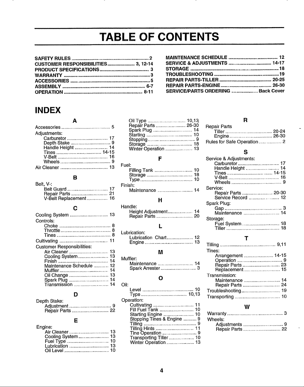
TABLE OF CONTENTS
SAFETY RULES ........................................................... 2
CUSTOMER RESPONSIBIUTIES ..................... 3, 12-14
PRODUCT SPECIFICATIONS ...................................... 3
WARRANTY .................................................................. 3
ACCESSORIES ............................................................. 5
ASSEMBLY ............................................................... 6-7
OPERATION ............................................................ 8-11
INDEX
A
Accessories ......................................................5
Adjustments:
Carburetor .............................................17
Depth Stake .......................................9
Handle Height .............................14
Tines .................................................14-15
V-Belt ..............................................16
Wheels ..............................................9
Air Cleaner ...................................... 13
B
Belt, V<
Belt Guard ..........................................17
Repair Parts .....................................21
V-Belt Replacement ......................16
C
Coo}ing System ..........................................13
Controls:
Choke ...........................................8
Throttle ..............................................8
Tines ................................................8
Cultivating .....................................................11
Customer Responsibilities:
Air Cleaner .........................................13
Cooling System ...........................13
Finish ............................................14
Maintenance Schedule ................12
Muffler. ...............................................14
Oil Change ....................................13
Spark Plug ..............................................14
Transmission ..............................14
D
Depth Stake:
Adjustment ......................................9
Repair Parts ................................22
E
Engine:
Air Cleaner ........................................t3
Cooling System ................................13
Fuel Type ........................................10
Lubrication .................................i3
Oil Level .......................................i0
Oil Type ......................................10,13
Repair Parts ..........................26-30
Spark Plug .....................................14
Starting ................................................10
Stopping ..........................................................9
Storage ..................................................18
Winter Operation ..............................13
Fuel:
Filling Tank ........................................t0
Storage ..........................................18
Type ...................................................10
Finish:
Maintenance ........................................14
Handle:
Height Adjustment ...........................14
Repair Parts ......................................20
Lubrication:
Lubrication Chart .........................12
Engine ...............................................13
Muffler:
Maintenance .................................14
Spark Arrester. ...............................3
Oil:
Level ................................................10
Type ..............................................10,13
Operation:
Cultivating ......................................11
Fill Fuel Tank ............................ 10
Starting Engine ........................ 10
Stopping Tines & Engine .......... 9
Tilling .....................................................9
Tilling Hints .........................................11
Tine Operation ........................................9
Transporting Tiller. .......................t0
Winter Operation .............i.............13
MAINTENANCE SCHEDULE ..................................... 12
SERVICE & ADJUSTMENTS ................................ 14-17
STORAGE ................................................................... 18
TROUBLESHOOTING ................................................. 19
REPAIR PARTS-TILLER ....................................... 20-25
REPAIR PARTS-ENGINE ...................................... 26-30
SERVICEJPARTS ORDERING .................... Back Cover
R
Repair Parts
Tit{er ...........................................................20-24
Engine ..........................................26-30
Rules for Safe Operation ........................2
S
F
H
L
M
O
Service & Adjustments:
Carburetor .....................................17
Handle Height .............................14
Tines .......................................14-15
V-Belt .............................................16
Wheels ...................................................... 9
Service:
Repair Parts ...........................20-30
Service Record ...........................12
Spark Plug:
Gap .....................................................3
Maintenance .................................14
Storage:
Fuel System ................................18
Tiller .............................................................18
T
Tilling .......................................................9,11
Tines:
Arrangement ................................14-15
Operation ...............................................9
Repair Parts ...............................23
Replacement .......................................15
Transmission:
Maintenance ................................14
Repair' Parts ................................24
Troubleshooting .......................................19
Transporting .......................................I0
W
Warranty ............................................................3
Wheels:
Adjustments ....................................9
Repair Parts ..................................22
4
ACC
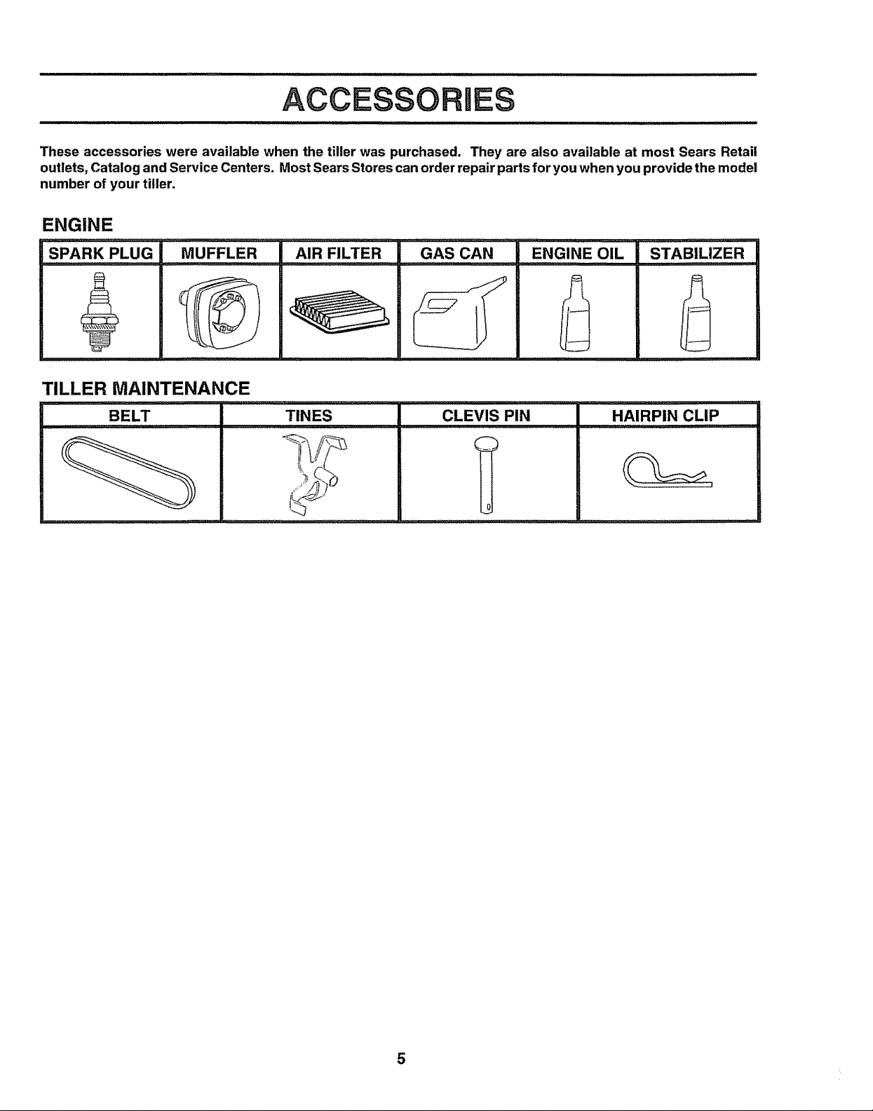
These accessories were available when the tiller was purchased. They are also available at most Sears Retail
outlets, Catalog and Service Centers. Most Sears Stores can order repair parts for you when you provide the model
number of your tiller.
ENGINE
Rm
SPARK rpLUG
MUFFLER
_L
TILLER MAINTENANCE
BELT TINES CLEVIS PIN
AIR FILTER GAS CAN
HAIRPIN CLIP
0
5

MBLY
Your new tiller has been assembled at the factory with exception ofthose parts left unassembled for'shipping purposes, To
ensure safe and proper operation of your tiller' all partsand hardware you assemble must be tightened securely. Use the
correct tools as necessary to insure proper tightness°
TOOLS REQUIRED FOR ASSEMBLY
A socket wrench set will make assembly easier,, Standard
wrench sizes are listed.
(1) Utility knife
(1) Screwdriver
(I) Pair of pliers
(2) 1/2" wrenches
................ , ,, ,,, ,, ,,,,,,,,,,,,,,..,,,...,,
CONTENTS OF HARDWARE PACK
I J I I II I lUUlIIIlUlIIII
OPERATOR'S POSITION (See Fig. 1)
When right or left hand is mentioned in this manual, it
means when you are in the operating position (standing
behind tiller handles),
FRONT
LEFT RIGHT
OPERATOR'S
POSITION
FIG. 1
........... lllj
I J L L II
(1) Manual
(2) Carriage Bolts 5/16-t8 UNC x 2-1/2
(2) Hex Bolts 5/16-18 x 1-1/4
, ,, ,,,,,,,,,,,,,,,,,,,,,,,,
(1) Plastic Cable Clip (1) Clevis Pin
Q
(2) Flange Locknuts
5/16-18 UNC
Q
(2) Hex Nuts 5/t6-18
6
(1) Washer
(1) Cotter Pin 9/32 x 1/2 x 14 Gauge
)
(1) Reverse Rod Bracket
©
(_(1) Bushing
0 I
(2) Lock Washers 5/16
UNPACK CARTON
LY
A
i CAUTION: Be careful Of exposed a
staples when handling or disposing of !
cartoning materia I, !
IMPORTANT: WHEN UNPACKING AND ASSEMBLING
TILLER, BE CAREFUL NOT TO STRETCH OR KiNK
CABLE(S)
= Cut cable ties securing handle column.
= Slowly lift handle column and lay it over tiller+
° Remove packing from carton+,Hardware pack isfound
in folded cardboard packing.
o Slide handle column onto handle mount,
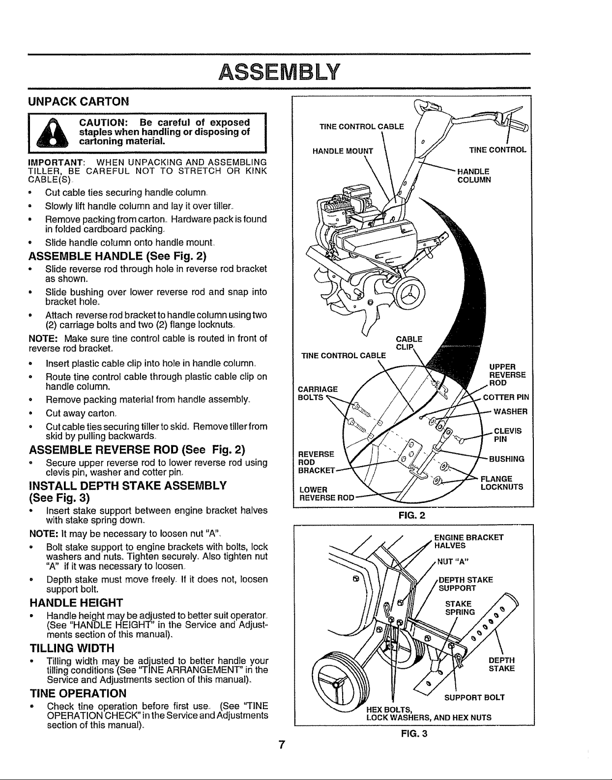
ASSEMBLE HANDLE (See Fig. 2)
o Slide reverse rod through hole in reverse rod bracket
as shown.
° Slide bushing over lower reverse rod and snap into
bracket hole,+
• Attach reverse rod bracket to handle column using two
(2) carriage bolts and two (2) flange tocknuts,,
NOTE: Make sure tine control cable is routed in front of
reverse rod bracket+
= Insert plastic cable clip into hole in handle column.,
o Route tine control cable through plastic cable clip on
handle column.
o Remove packing matedal from handle assembly+
° Cut away carton.
= Cut cable ties securing tiller to skid+ Remove tiller from
skid by pulling backwards+
ASSEMBLE REVERSE ROD (See Fig, 2)
o Secure upper reverse rod to lower reverse rod using
clevis pin, washer and cotter pin+
INSTALL DEPTH STAKE ASSEMBLY
(See Fig. 3)
• insert stake support between engine bracket halves
with stake spring down+,
NOTE: It may be necessary to loosen nut "A",
• Bolt stake support to engine brackets with botts, lock
washers and nuts. Tighten securely+ Also tighten nut
"A" if it was necessary to loosen.
° Depth stake must move freely+ If it does not, toosen
support bolt.
HANDLE HEIGHT
• Handle height may be adjusted to better suit operator.,
(See "HANDLE HEIGHT'' in the Service and Adjust-
ments section of this manual).
TILLING WIDTH
• T+lling width may be adjusted to better handle your
tilling conditions (See "TINE ARRANGEMENT" in the
Service and Adjustments section of this manual)°
TINE OPERATION
= Check tine operation before first use+, (See "FINE
OPERATION CHECK" in the Service and Adjustments
section of this manual),,
TfNE CONTROL CABLE
HANDLE MOUNT
TtNECONTROLCABLE
CARRIAGE
BOLTS
REVERSE
ROD
E
LOWER
7
TfNE CONTROL
COLUMN
CABLE
CLII:
\
LOCKNUTS
FIG. 2
ENGINE BRACKET
HALVES
STAKE
SUPPORT
SUPPORT BOLT
HEX BOLTS,
LOCK WASHERS, AND HEX NUTS
FIG. 3
UPPER
REVERSE
ROD
WASHER
PIN
DEPTH
STAKE

OPERATION
KNOW YOUR TILLER
READ THIS OWNER'S MANUAL AND SAFETY RULES BEFORE OPERATING YOUR TILLER.
Compare the illustrationswith your tillerto familiarize yourselfwith the location of variouscontrols and adjustments, Save
this manual for' future reference.
REVERSE "ftNE CONTRO!.
FORWARD TINE CONTROL
CHOKECONTROL
THROTTLE
CONTROL
DEPTH STAKE
RECOIL STARTER HANDLE
MEETS ANSI SAFETY REQUIREMENTS
Sears tillers conform to the safety standards of the American National Standards Institute,.
FORWARD TINE CONTROL - Engages tines in forward
direction,
REVERSE TINE CONTROL - Engages tines in reverse
direction,
CHOKE CONTROL - Used when starting a cold engine,.
TINE SHIELD
FIG. 4
THROTTLE CONTROL - Controls engine speed.
DEPTH STAKE - Controls forward speed and the depth at
which the tiller' will dig_
RECOIL STARTER HANDLE - Used to start the engine,
8
OPEBATn
The operation of any tiller can result in foreign objects thrown into the eyes, which can
result in severe eye damage. Always wear safety glasses or eye shields before starting
your tiller and while tilling. We recommend a wide vision safety mask over the spectacles
or standard safety glasses.
HOW TO USE YOUR TILLER
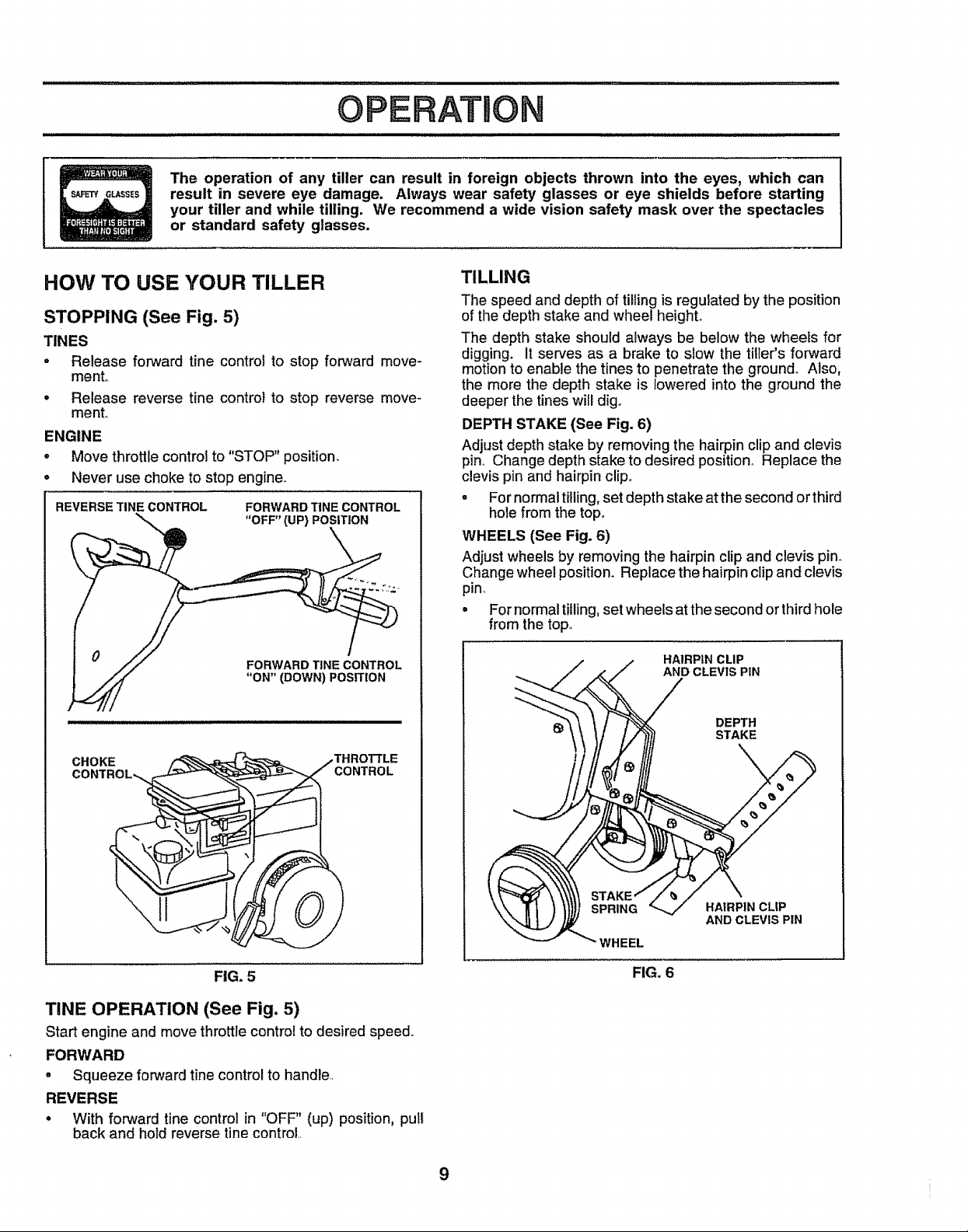
STOPPING (See Fig. 5)
TINES
• Release forward tine control to stop forward move-
mento
= Release reverse tine control to stop reverse move-
mento
ENGINE
. Move throttle controt to "STOP" position,
- Never use choke to stop engine.
REVERSE TINE CONTROL FORWARD TINE CONTROL
I " //./ FORWARD TINE CONTROL
/_ "ON" (DOWN) POSITION
TILLING
The speed and depth of tilling is regulated by the position
of the depth stake and wheel height.
The depth stake should always be below the wheets for
digging. It serves as a brake to slow the filler's forward
motion to enable the tines to penetrate the ground. Also,
the more the depth stake is lowered into the ground the
deeper the tines will dig.
DEPTH STAKE (See Fig. 6)
Adjust depth stake by removingthe hairpin clipand clevis
pin,, Change depth stake to desired position° Replace the
clevis pin and hairpin clip,,
° For normal tilling, set depth stake at the second or third
hole from the top.
WHEELS (See Fig. 6)
Adjust wheels by removing the hairpin clip and clevis pin°
Change wheel position_ Replace the hairpin clip and clevis
pin_
• For normal tilling, set wheels atthe second or third hole
from the top,,
HAIRPIN CLIP
AND CLEVIS PIN
DEPTH
STAKE
CHOKE
CONTROL_,
FIG. 5
TINE OPERATION (See Fig. 5)
Start engine and move throttlecontrol to desired speed..
FORWARD
• Squeeze forward tine control to handle,,
REVERSE
• With forward tine control in "OFF" (up) position, putt
back and hold reverse tine control,,
HAtRPIN CL|P
AND CLEVIS PIN
WHEEL
FIG, 6
9
ii
OPERATION
TRANSPORTING YOUR TILLER
CAUTION: Before lifting or transport,-
ing, allow tiller engine and muffler to
cool. Disconnectsparkplug wire. Drain
gasoline from fuel tank.
AROUND THE YARD
. Tip depth stake forward until it is held by the stake
spdng.
. Push tiller handles down, raising tines off the ground
• Push or pull tiller to desired location°
AROUND TOWN
° Disconnect spark plug wire.
• Drain fuet tank_
. Transport in upright positionto prevent oil leakage.
BEFORE STARTING ENGINE
IMPORTANT: BE VERY CAREFUL NOT TO ALLOW
DIRT TO ENTER THE ENGINE WHEN CHECKING OR
ADDING OILOR FUEL. USE CLEAN OILAND FUELAND
STORE IN APPROVED, CLEAN, COVERED
CONTAINERS. USE CLEAN FILL FUNNELS.
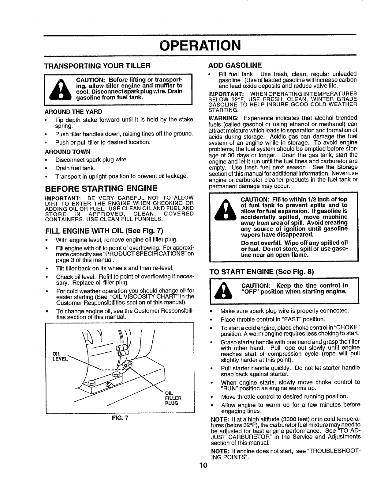
FILL ENGINE WITH OIL (See Fig. 7)
• With engine level, remove engine oilfiller plug.
° Fillengine withoil to pointof overflowing. Forapproxi-
mate capacitysee "PRODUCT SPECIFICATIONS" on
page 3 of this manual°
• Tilt tillerback on its wheels and then re-leveL
° Check oil level. Refillto pointof overflowingifneces-
saryo Replace oilfiller plug_
. For cold weather operation you should change oilfor
easterstarting (See OIL VISCOSITY CHART' Jnth
Customer Responsibilitiessection of this manual).
° To change engine oil, see the Customer Responsibili-
tiessection of thismanual.
OIL
FILLER
PLUG
FIG. 7
ADD GASOLINE
• Fitl fuel tank° Use fresh, c_ean, regular unleaded
gasoline_ (Use of leaded gasoline will increase carbon
and lead oxide deposits and reduce valve life.
IMPORTANT: WHEN OPERATING IN TEMPERATURES
BELOW 32°F, USE FRESH, CLEAN, WINTER GRADE
GASOLINE TO HELP INSURE GOOD COLD WEATHER
STARTING
WARNING: Experience indicates that alcohol blended
fuels (called gasohol or using ethanol or methanol) can
attract moisture which leads to separation and formation of
acids during storage, Acidic gas can damage the fuel
system of an engine while in storage. To avoid engine
problems, the fuel system should be emptied before stor-
age of 30 days or longer'. Drain the gas tank, start the
engine and Iet it run until the fuel lines and carburetor are
empty. Use fresh fuel next season. See the Storage
section of this manual for'additional information. Never use
engine or carburetor cleaner products in the fuel tank or
_ermanent damage may occur,,
CAUTION: Fill to within 1t2 inch of top
of fuel tank to prevent spills and to
A
allow for fuel expansion, If gasoline is
accidentally spilled, move machine
away from area of spill, Avoid creating
any source of ignition until gasoline
vapors have disappeared.
Do not overfill. Wipe off any spilled oil
or fuel. Do not store, spill or use gaso-
line near an open flame.
i iiii iii i
TO START ENGINE (See Fig. 8)
"OFF" position when starting engine.
CAUTION: Keep the tine control in
• Make sure spark plug wire is properly connected.
• Place throttle control in "FAST" position,
° Tostart acoldengine; placechoke controlin "CHOKE"
position. A warm engine requireslesschokingto start_
• Grasp starter handle with one handand graspthe tiller
with other hand. Pull rope out slowly until engine
reaches start of compression cycle (rope will pult
slightly harder at this point)_
° Pull starter handle quickly_ Do not let starter' handle
snap back against starter.
• When engine starts, slowly move choke control to
"RUN" positionas engine warms up.
o Move throttlecontrolto desired running position.
= Allow engine to warm up for a few minutes before
engaging tines.,
NOTE: If at a high altitude (3000 feet) or incold tempera-
tures(below32°F), thecarburetorfuel mixture may need to
be adjusted for best engine performance, See 'q'O AD-
JUST CARBURETOR" in the Service and Adjustments
section of this manual
NOTE: If engine does not start, see "TROUBLESHOOT-
ING POINTS".
10
 Loading...