

Craftsman 917293650 Owner’s Manual
Caution:
Read and follow
all Safety Rules
and instructions
Before Operating
This Equipment
©
®
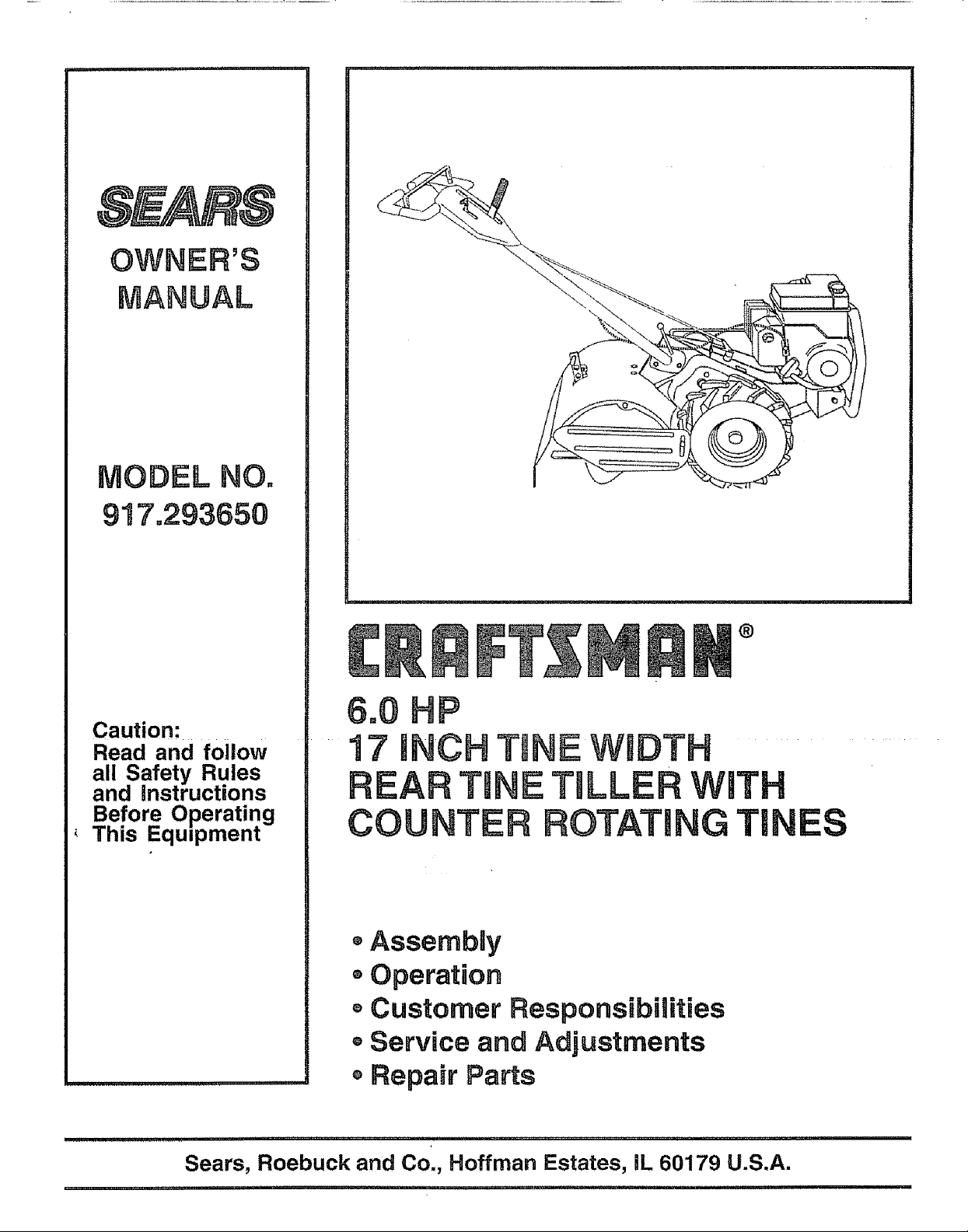
6.0 HP
17 iNCH TINE WIDTH
TU TULLERWiTH
COUNTER F_OTATI TIN
®Assembly
- Operation
Customer Responsibilities
oService and Adjustments
, Repa_r Parts
i iii ,, i i i ................................. i ,1111,1,,111,,111111,,i,i
Sears, Roebuck and Co., Hoffman Estates, IL 60179 U.S.A.
i, ii ,, iii
SAFETY RULES
Safe Operation Practices for Walk-Behind Powered Rotary Tillers
TRAINING
, Read the Owner's Manual carefulty_ Be thoroughly
familiar with the controls and the proper use of the
equipment. Know how to stop the unit and disengage
the controls quickly
• Never allow children to operate the equipment.. Never
allow adutts to operate the equipment without proper
instruction
• Keep the area of operation clear of all persons, particu-
larly small children, and pets.
PREPARATION
• Thoroughly inspect the area where the equipment is to
be used and remove all foreign objects°
• Disengage all clutches and shift into neutral before
starting the engine (motor).
• Do not operate the equipment without wearing ad-
equate outer garments.r Wear footwear that will im-
prove footing on slippery surfaces°
• Handle fuel with care; it is highly flammable
• Use an approved fuel container.
. Never add fuel to a running engine or hot engine
. Fill fuel tank outdoors with extreme care. Never fi!I fuel
tank indoors.
- Replace gasoline cap securely and ciean up spilled
fuel before restarting.
o Use extension cords and receptacles as specified by
the manufacturer for all units with electric drive motors
or electric starting motors.
• Never attempt to make any adjustments while the
engine (motor) is running (except where specifically
recommended by manufacturer).
OPERATION
o Do not put hands or feet near or under rotating parts.
= Exercise extreme caution when operating on or cross-
inggravel drives, walks, or roads, Stay alert for hidden
hazards or traffic, Do not carry passengers.
- After striking a foreign object, stop the engine (motor),
remove the wire from the spark plug, thoroughly in-
spect the tiller for any damage, and repair the damage
before restarting and operating the tiller
° Exercise caution to avoid slipping or falling
• If the unit should start to vibrate abnormally, stop the
engine (motor) and check immediately for the cause
Vibration is generally a warning of trouble
• Stop the engine (motor) when leaving the operating
position,
o Take all possible precautions when leaving the ma-
chine unattended. Disengage the tines, shift into
neutral, and stop the engine.
° Before cleaning, repairing, or inspecting, shut off the
engine and make certain all moving parts have stopped.
Disconnect the spark plug wire, and keep the wire
away from the plug to prevent accidental starting,
Disconnect the cord on electric motors.
. Do not run the engine indoors; exhaust fumes are
dangerous,
. Never operate the tiller without proper guards, plates,
or other safety protective devices in place,
= Keep children and pets away
• Do not overload the machine capacity by attempting to
till too deep at too fast a rate.
• Never operate the maclqine at high speeds on slippery
surfaces. Look behind and use care when backing.
• Never allow bystanders near the unit
o Use only attachments and accessories approved by
the manufacturer of the tiller (such as wheel weights,
counterweights, cabs, and the like).
. Never operate the tiller without good visibility or light
• Be careful when tilling in hard ground. The tines may
catch in the ground and propel the tiller forward, If this
occurs, tet go of the handlebars and do not restrain the
machine
MAINTENANCE AND STORAGE
° Keep machine, attachments, and accessories in safe
working condition.
- Check shear pins, engine mounting bolts, and other
bolts at frequent intervals for proper tightness to be
sure the equipment is in safe working condition.
Never store the machine with fuel inthe fuel tank inside
a building where ignition sources are present, such as
hot water and space heaters, clothes dryers, and the
like. Allow the engine to cool before storing in any
enclosure.
o Atways refer to the operator's guide instructions for
important details if the tiller is to be stored for an
extended period.
- IMPORTANT-
CAUTIONS, IMPORTANTS, AND NOTES ARE A MEANS
OF ATTRACTING ATTENTION TO IMPORTANT OR
CRITICAL INFORMATION IN THIS MANUAL
IMPORTANT: USED TO ALERT YOU THAT THERE ISA
POSSIBILITY OF DAMAGING THIS EQUIPMENT.
NOTE: Gives essential information that witl aid you to
better understand, incorporate, or execute a particular set
of instructions,.
i, ,,Ul i , i , lu ,,UllllUr,_l ......
t ,_ Look for this symbol to point out im-
I _ portant safety precautions. It means
I _ CAUTION!!! BECOMEALERT!!! YOUR
I , u , i ii u i, i,i1_1i,Ulllllll
,,,, ,,,,,,,,,,,,,,,,,,,,,,,
SAFETY IS INVOLVED
plug wire and place wire where it can-
CAUTION: Always disconnect spark
not contact spark plug in order to pre-
vent accidental starting when setting
up, transporting, adjusting or making
repairs.
i,UUlll ii, i ,,Ul,i,
WARNING ...........
The engine exhaust from this product con-
tains chemicals known to the State of .Califor-
nia to cause cancer, birth defects, or other
reproductive harm.
u, i ilur Ullll,, iii ...... i,, ii,u,,
CONGRATULATIONS on your purchase of a Sears Tiller,
It has been designed, engineered and manufactured to
give you the best possible dependability and performance.
Should you experience any problems you cannot easily
remedy, pfease contact your' nearest authorized Sears
Service Center/Department. They have competent, welF
trained technicians and the proper tools to service or repair
this unit.
PIease read and retain this manual The instructions will
enable you to assemble and maintain your tiller' propedy
Always observe the "SAFETY RULES",
PRODUCT SPECIFICATIONS
HORSEPOWER: 6,0 HP
DISPLACEMENT: 11.88 cu_ino(195cc)
GASOLINE CAPACITY: 4 Quarts
Unleaded Regular
I
i OIL (API-SF/SG) : SAE 30 (Above 32°F)
(CAPACITY: 20 oz.) SAE 5W-30 (Befow 32°F)
SPARK PLUG :
MODEL
NUMBER 917.293650
SERIAL
NUMBER
DATE OF
PURCHASE
THE MODEL AND SERIAL NUMBERS WILL BE
FOUND ON THE MODEL PLATE ATTACHED TO
THE TOP OF THE TRANSMISSION,
YOU SHOULD RECORD BOTHSERIALNUMBER
AND DATE OF PURCHASE AND KEEPIN A SAFE
PLACE FOR FUTURE REFERENCE.
IMPORTANT: THIS UNIT IS EQUIPPED WITH AN INTERNAL COMBUSTION ENGINE AND SHOULD t_OT BE USED ON
OR NEAR ANY UNIMPROVED FOREST-COVERED, BRUSH-COVERED OR GRASS COVERED LAND UNLESS THE
ENGINE'S EXHAUST SYSTEM IS EQUIPPED WITH A SPARK ARRESTER MEETING APPLICABLE LOCAL OR STATE
LAWS (IF ANY)._ IF A SPARK ARRESTER IS USED, tT SHOULD BE MAINTAINED IN EFFECTIVE WORKING ORDER BY
THE OPERATOR
IN THE STATE OF CALIFORNIA THE ABOVE IS REQUIRED BY LAW (SECTION _4442 OF THE CALIFORNIA PUBLIC
RESOURCES CODE). OTHER STATES MAY HAVE SIMILARLAWS_ FEDERAL LAWS APPLY ON FEDERAL LANDS+
SEE YOUR SEARS AUTHORIZED SERVICE CENTER/DEPARTMENT FOR SPARK ARRESTER. REFER TO THE REPAIR
PARTS SECTION OF THIS MANUAL FOR PART NUMBER.
(GAP: 030")
MAINTENANCE AGREEMENT
A Sears Maintenance Agreement isavailable on this prod-
uct. Contact your nearest Sears store for details.
CUSTOMER RESPONSIBILITIES
° Read and observe the safety rules.
o Follow a regular schedule in maintaining, caring for and
using your tiller.
o Follow the instructions under the "Customer
Responsibilities" and "Storage" sections of this Owner's
Manual..
Champion
RN4C
LIMITED TWO YEAR WARRANTY ON CRAFTSMAN TILLER
For two years from date of purchase, when this Craftsman Ti_ler is maintained, lubricated, and tuned up according to
the operating and maintenance instructions in the owner's manual, Sears will repair free of charge any defect in
material or workmanship.
This W&rranty does not cover:
o Expendable items which become wom during normal use, such as tines, spark plugs, air cleaners and belt&
° Repairs necessary because of operator abuse or negligence, including bent crankshafts and the failure to
maintain the equipment according to the instructions contained in the owneCs manual.
o If this Craftsman Tiller is used for commercial or rental purposes, this Warranty applies for only 30 days from the
date of purchase.
WARRANTY SERVICE IS AVAILABLE BY RETURNING THE CRAFTSMAN TILLER TO THE NEAREST SEARS
SERVlCE CENTER/DEPARTMENT IN THE UNITED STATE& THIS WARRANTY APPLIES ONLY WHILE THIS
PRODUCT IS IN USE IN THE UNITED STATES.
This Warranty gives you specific legal rights, and you may also have other rightswhich vary from state to state.
SEARS, ROEBUCK AND CO. D/817 WA, HOFFMAN ESTATES, ILLINOIS 60179
3
i, u nl ,,in,nl lun , i
TABLE OF CONTENTS
'll'n"lllHirll' i i i 'u nllu Ull'UlU''' i' i
SAFETY RULES ............................................................ 2
CUSTOMER RESPONSIBILITIES ...................... 3,13-15
PRODUCT SPECIFICATIONS ...................................... 3
WARRANTY ................................................................... 3
ACCESSORIES ............................................................. 5
ASSEMBLY ................................................................ 6-8
OPERATION ................ ;......;..................................... 9-12
UNDEX
A
Accessories ........................................... 5
Adjustments:
Carburetor .....................................18
Depth Stake .................................10
Handle Height ...............................15
Side Shields ..................................11
Throttle .........................................18
Tines ............................................ 17
V-Belt (Ground Drive) .............. 16
Air Cleaner ....................................... 14
B
Belt:
Belt Guard .................................. 16
Repair Parts ............................. 22
V-Belt (Ground Drive) ............. 16
C
Cooling System ................................. 14
Controls:
Choke ...............................................9
Throttle .......................................... 9
Drive (Tines) ................................ 9
Cultivating ............................................12
Customer Responsibilities:
Air Cleaner .......................................14
Cooling System .............................14
Finish ..............................................15
Maintenance Schedule ............ 13
Muffler ............................................ 15
Oil Change .................................. 14
Spark Plug ................................. 15
Tines ................................................17
Transmission ...............................15
WBelt (Ground Drive) ............... 16
D
Depth Stake:
Adjustment ..............:......................t0
Repair Parts ...................................25
E
Engine:
Air Cleaner ................................. 14
Cooling System ........................ 14
FuelType ......................................11
Engine (conrd)
Lubrication ................................ 14
Oil Level .........................................11
Oil Type .....................................11,14
Spark Plug ......................................15
Starting .............................................12
Stopping ..........................................10
Storage .................................................19
Winter Operation ........................14
Fuel:
Filling Tank ...... .................................. t 1
Storage ............................................19
Type ............................................ 11
Finish:
Maintenance ........................................15
Handle:
Height Adjustment .....................15
Repair Parts .................................21
Lubrication:
Lubrication Chart ...................13
Engine .........................................14
Muffler:
Maintenance ................................15
Spark Arrester ...............................3
Oil:
Level .............................................11
Type .......................................... 11,14
Operation:
Cultivating .....................................12
Fill Fuel Tank ....................................1!
Starting Engine ...........................12
Stopping Tines & Engine ...........10
Tilling ...............................................10
Tilling Hints ..................................12
Tine Operation .......................... 10
Transporting Tiller ...................... 11
Winter Operation ........................14
MAINTENANCE SCHEDULE ...................................... 13
SERVICE & ADJUSTMENTS ................................. 15-18
STORAGE ................................................................... 19
TROUBLESHOOTING ................................................. 20
REPAIR PARTS-TILLER ........................................ 21-27
REPAIR PARTS-ENGINE ...................................... 28-33
SERVICEIPARTS ORDERING ................ BACK COVER
R
Repair Parts:
Tiller .......................................................2!-27
Engine .........................................28-33
Rules for Safe Operation .................. 2
S
Service & Adjustments:
Carburetor .......................................18
Handle Height ...................................I5
Side Shields ....................................11
Throttle ..........................................t8
Tines ...............................................17
V-Belt (Ground Drive) ............... t6
Wheels .............................................15
Service:
Repair Parts ...................................21-33
H
L
O
Service Record ............................13
Shear Pins:
Operation ...................................12
Repair Parts ................................26
Spark Plug:
Gap ............................................. 3
Maintenance ........................... 15
Storage:
Fue! System ............................... 19
Tiller ........................................... 19
Tilling ...................................................10,12
Tines:
Arrangement/Replacement ..... 17
Operation .................................. 10
Repair Parts .................................26
Shear Pins ..........................................12
Transmission:
Maintenance ................................15
Repair Parts ................................24
Troubleshooting .................................20
Transporting ...........................................11
W
Warranty .....................................................3
Wheels:
Removal ................................... 15
Repair Parts ..............................23
4
.......................................... i,, 'IMIIIIIIIII
ACCESSORIES
ii ii, i ii '111,iii, ,111.................... i i i
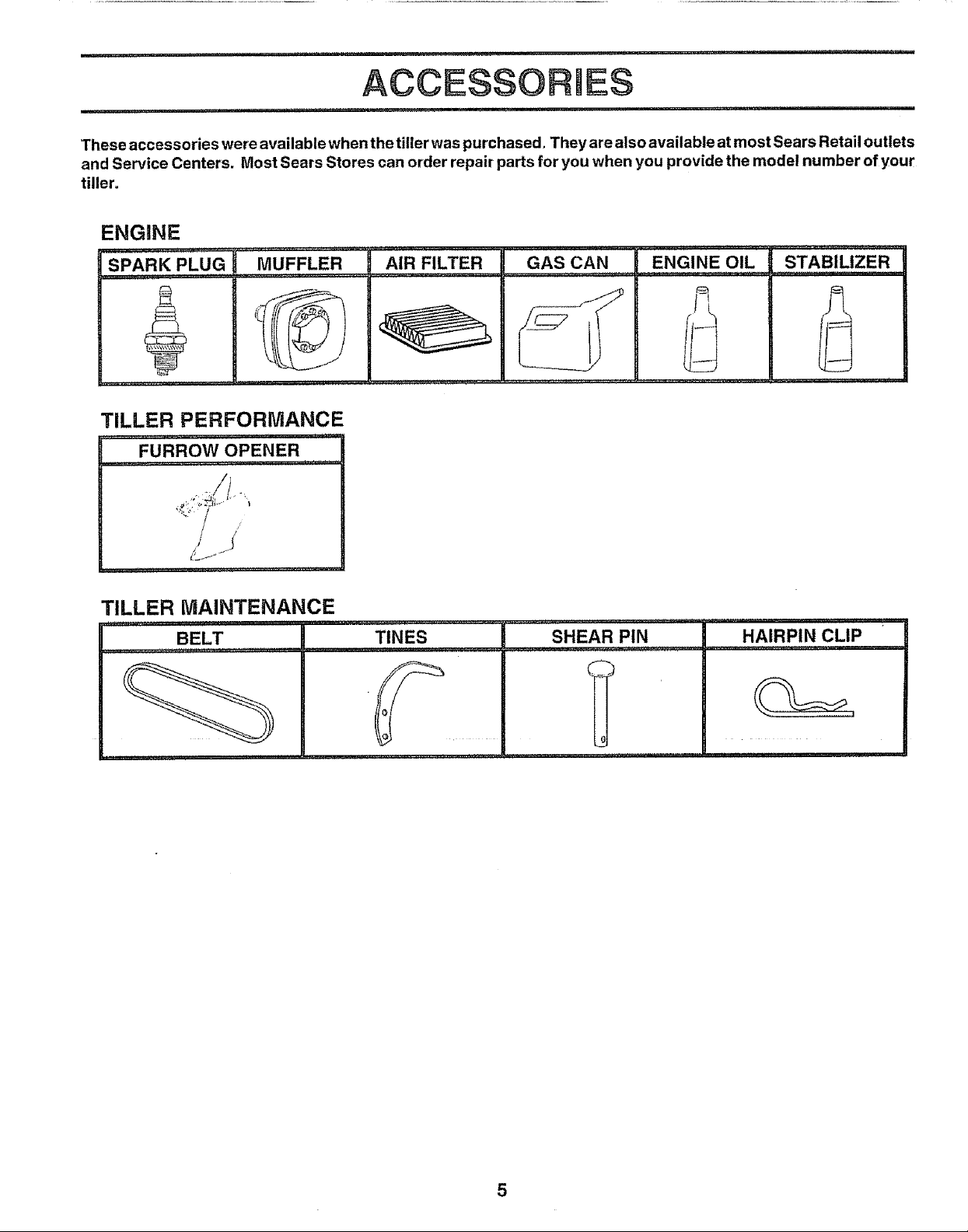
These accessories were available when the tiller was purchased. They are also available at most Sears Retail outlets
and Service Centers. Most Sears Stores can order repair parts for you when you provide the model number of your
tiller=
ENGINE
SPARK PLUG
, ,, ,, H,, ,,,,,_,_,,,
MUFFLER
r,,,
AIR FILTER GAS CAN
ENG'i'NE"'O'iL STABILIZER
TILLER PERFORMANCE
_,r,T,,
FURROW OPENER
TILLER MAINTENANCE
BELT
,, ,,,
L '',,' "
TINES SHEAR PIN HAIRPIN CLIP
0
, ,,,,.,,,,,
5
i ii iii ii i ii
BLY
i ii ............................................................
Your new flier has been assembled at the factory with exception of those parts left unassembled for shipping purposes To
ensure safe and proper operation of your tiller all parts and hardware you assemble must be tightened securely Use the
correct tools as necessary to insure proper tightness
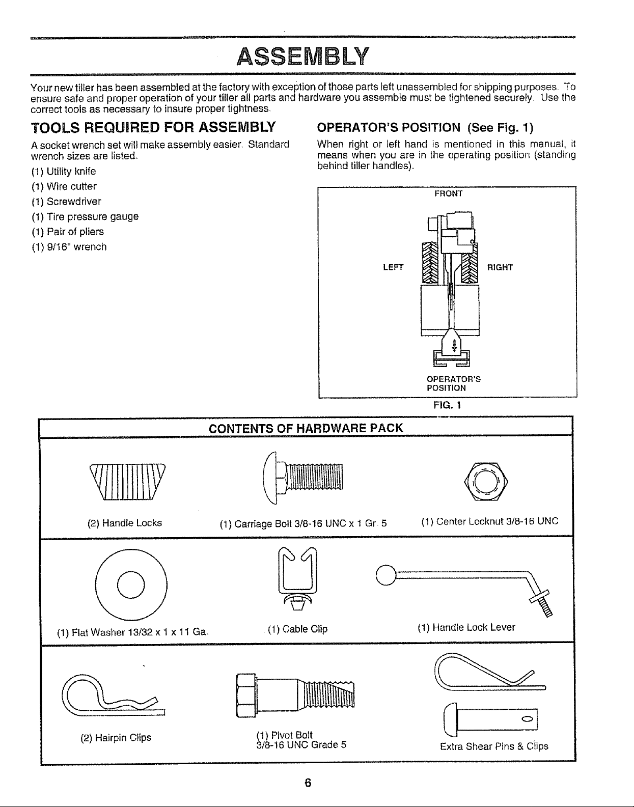
TOOLS REQUIRED FOR ASSEMBLY OPERATOR'S POSITION (See Fig. 1)
A socket wrench set will make assembly easier Standard When right or left hand is mentioned in this manual, it
wrench sizes are listed_
(1) Utility knife
(1) Wire cutter
(1) Screwdriver
(1) Tire pressure gauge
(t) Pair of pliers
(1) 9/16" wrench
means when you are in the operating position (standing
behind tiller handles)°
FRONT
LEFT RIGHT
(2) Handle Locks
,,,, ii,,111
(1) Flat Washer 13t32 x I x 11 Ga,
i i, i iii
CONTENTS OF HARDWARE PACK
(1) Carriage Bolt 3/8-16 UNC x I Gr 5
........................... ,, ,,,,,,,,,,,,,
i IIIIIIIH i iiiiiiiir.........
(1) Cable Clip
ii i iiiii
OPERATOR'S
POSITION
FIG. 1
G
(1) Center Locknut 3/8-16 UNC
(1) Handle Lock Lever
L_ ,i,
(2) Hairpin Clips
(1) Pivot Bolt
3/8-16 UNC Grade 5
6
Extra Shear Pins & Ciips
,,11,,,,,i,............... i, , , ,........ 1,1,1 L'L_
ASSEMBLY
..................... i, , i ,,,i,i1,,,,,i,i, ,i,i1,,,,,i,,,i,ii, ii, , i , ,
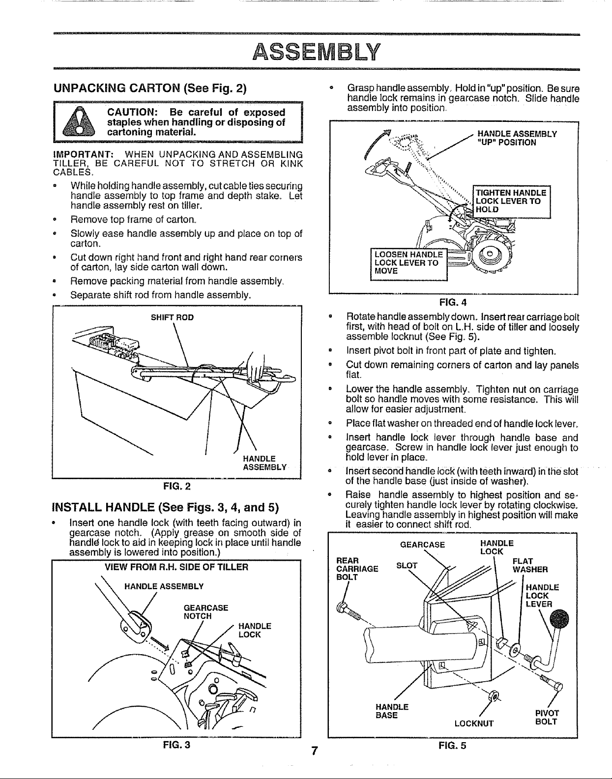
UNPACKING CARTON (See Fig, 2) o Grasp handle assembly, HoIdin"up"position. Be sure
handle lock remains in gearcase notch, Slide handle
assembly into position,,
",j._., _:,: "UP" POSITION
IMPORTANT; WHEN UNPACKING AND ASSEMBLING
TILLER, BE CAREFUL NOT TO STRETCH OR KINK
CABLES,,
, While holding handle assembly, cutcabletiessecuring
handle assembly to top frame and depth stake_ Let
handle assembly rest on tiller,
o Remove top frame of carton°
• Slowly ease handle assembly up and place on top of
carton,
o Cut down right hand front and right hand rear'corners
of carton, lay side carton wall down.
• Remove packing material from handle assembly°
• Separate shift rod from handle assembly,
SHIFT ROD
HANDLE
ASSEMBLY
FIG. 2
INSTALL HANDLE (See Figs. 3, 4, and 5)
o Insert one handle lock (with teeth facing outward) in
gearcase notch_ (Apply grease on smooth side of
handl_ lock to aid in keeping lock in place until handle
assembly is lowered into position.)
VIEW FROM R,H. SIDE OF TILLER
\ HANDLE ASSEMBLY
GEARCASE
NOTCH
HANDLE
LOCK
. Rotate handle assembly down. Insert rear carriage bolt
= Insert pivot bolt in front part of plate and tighten.
o Cut down remaining corners of carton and lay panels
= Lower the handle assembly,, Tighten nut on carriage
• Place flat washer on threaded end of handle lock lever.
° Insert handle 10ck lever" through handle base and
= Insert second handle 10Ck(with teeth inward) in the slot
• Raise handle assembly to highest position and se-
,_,:: .:_,_ +,j.f,_f HANDLE ASSEMBLY
LOCK LEVERTO
HOLD
__ TIGHTENHANDLE
LOOSEN HANDLE _
LOCK LEVER TO
MOVE I
FIG. 4
first, with head of bolt on LH. side of tiller and loosely
assemble Iocknut (See Fig. 5).
flat.
bolt so handle moves with some resistance. This wil!
allow for easier adjustmenL
gearcase. Screw in handle lock lever just enough to
hold lever in place.
of the handle base (just inside of washer).
curely tighten handle lock lever by rotating clockwise.
Leaving handle assembly in highest position will make
it easier to connect shift rod.
GEARCASE HANDLE
LOCK
REAR FLAT
CARRIAGE SLOT WASHER
BOLT _ '
LOCK
LEVER
HANDLE
FIG. 3
HANDLE "_
BASE PIVOT
7
LOCKNUT BOLT
FIG. 5
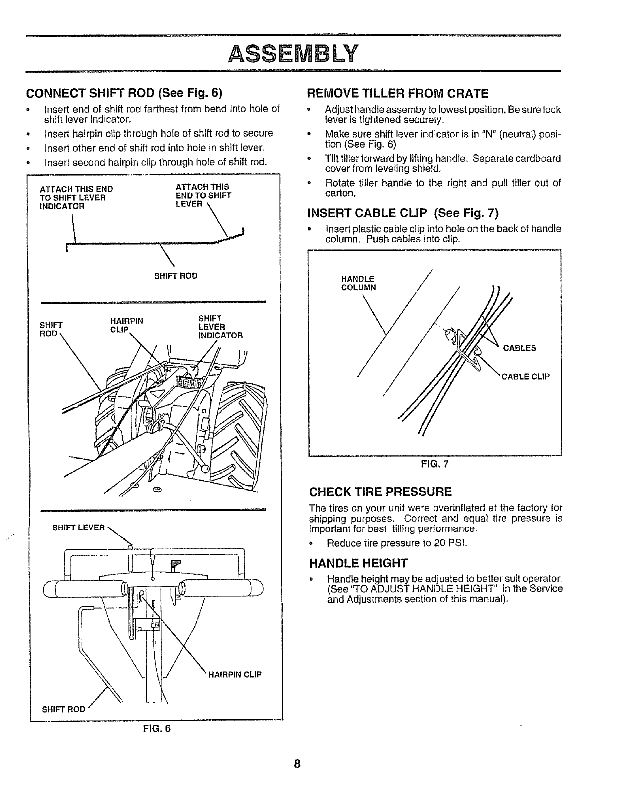
CONNECT SHIFT ROD (See Fig. 6)
o Insert end of shift rod farthest from bend into hole of
shift lever indicator.
• Insert hairpin clip through hole of shift rod to securer
° Insert other end of shift rod into hole in shift lever.
° Insert second hairpin clip through hole of shift rod°
ATTACHTHISEND ATTACHTHIS
TOSHIFTLEVER ENDTOSHIFT
INDICATOR LEVER _
REMOVE TILLER FROM CRATE
, Adjust handte assembyto lowest position, Besure lock
lever is tightened securely°
o Make sure shift lever indicator is in "N" (neutral) posi-
tion (See Fig. 6)
° Tilt tiller forward by lifting handle° Separate cardboard
cover from leveling shield.
o Rotate tiller handle to the right and pull tiller out of
carton.
INSERT CABLE CLIP (See Fig. 7)
° Insert plastic cable clip into hole on the back of handle
column_ Push cables into clip.
SHIFT
SHIFT
SHIFT ROD
...................... i,i i,,
HAIRPIN SHIFT
CLIP LEVER
INDICATOR
i ii i
HANDLE
COLUMN
-\
CABLES
FIG. 7
CHECK TIRE PRESSURE
The tires on your unit were overinflated at the factory for
shipping purposes, Correct and equal tire pressure is
important for best tilling performance°
o Reduce tire pressure to 20 PSI°
HANDLE HEIGHT
• Handle height may be adjusted to better suit operator.
(See 'TO ADJUST HANDLE HEIGHT" in the Service
and Adjustments section of this manual)_
SHIFT ROD
HAIRPIN CLIP
FIG. 6
8
L_ ,.i ..... I ' ,.... I" "'111"'11'11'""='"1'""11'1"1 ........ I1'1 I1'11"11"1'1111 , , ,I,,,,,,,I,, "1"'11'1' '
OPEF ATmON
.,, .............. ,,.. i ,,,i i, i ii iii, ,i, ,i,,i,,,i,M'IIII "11'"'1''11I
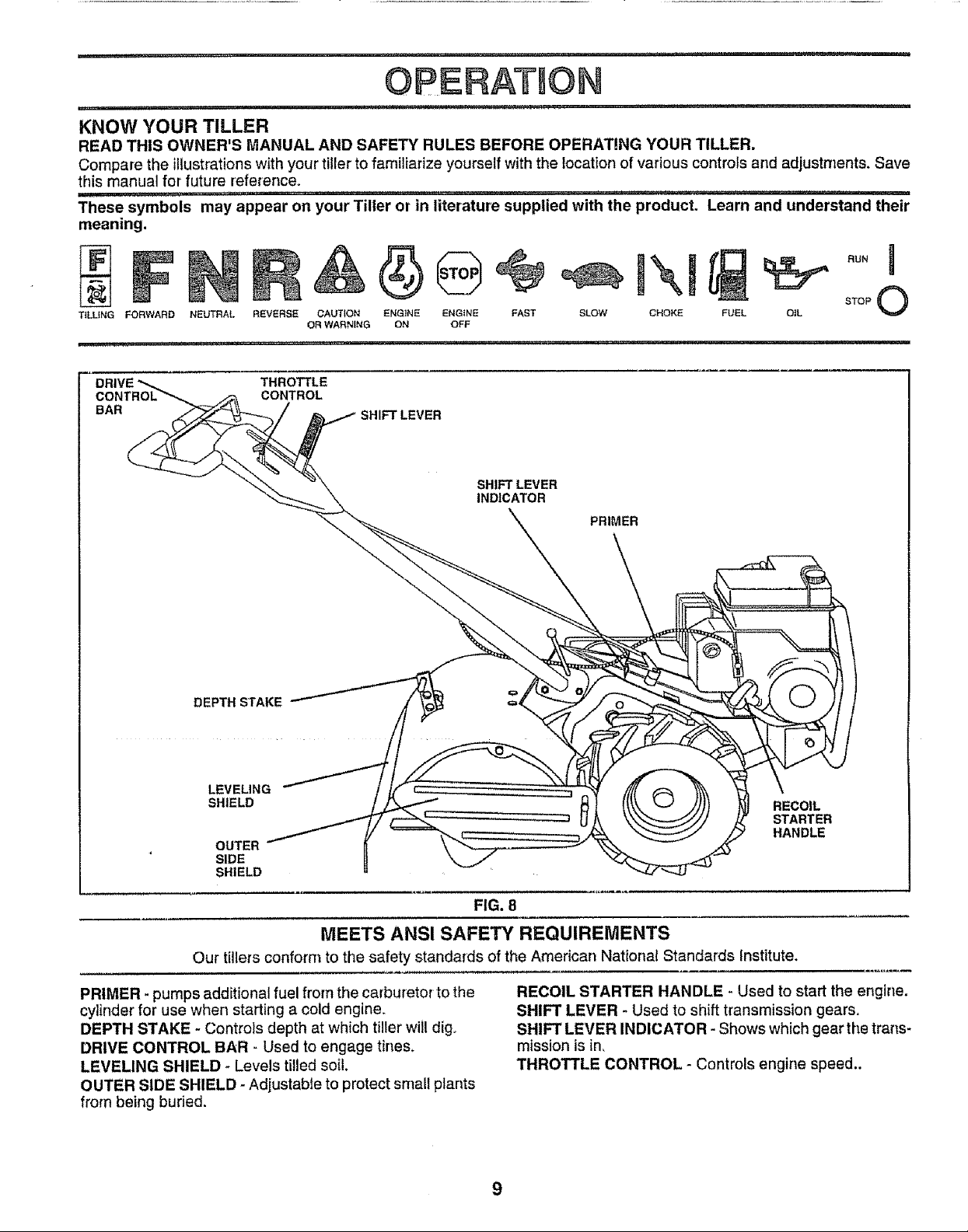
KNOW YOUR TILLER
READ THIS OWNER'S MANUAL AND SAFETY RULES BEFORE OPERATING YOUR TILLER,
Compare the illustrations with your tiller to familiarize yourself with the location of various controls and adjustments, Save
this manual for future reference°
These symbols may appear on your Tiller or in literature supplied with the product. Learn and understand their
meaning.
T{LL|NG FORWARD NEUTRAL REVERSE
DRIVE _ THROTTLE
CONTROL _ CONTROL
BAR
DEPTH STAKE _
CAUTION ENG1NE ENGINE
OR WARNING ON OFF
FAST SLOW
SHIFT LEVER
INDICATOR
CHOKE FUEL OtL
STOP O
PRIMER
LEVELING _ _ _ _ _\_
SHIELD
OUTER
SIDE
SHIELD
MEETS ANSI SAFETY REQUIREMENTS
Our tillers conform to the safety standards of the American National Standards Institute,
PRIMER - pumps additional fuel from the carburetor to the
cylinder for use when starting a cold engine,
DEPTH STAKE - Controls depth at which tiller will dig
DRIVE CONTROL BAR _ Used to engage tines,
LEVELING SHIELD * Levels tilled soil.
OUTER SIDE SHIELD - Adjustable to protect small plants
from being buried.
RECOIL
STARTER
HANDLE
FIG. 8
RECOIL STARTER HANDLE - Used to start the engine,
SHIFT LEVER - Used to shift transmission gears,
SHIFT LEVER INDICATOR - Shows which gear the trans-
mission is in_
THROTTLE CONTROL - Controls engine speed..
The operation of any tiller can result in foreign objects thrown into the eyes, which can
result in severe eye damage. Always wear safety glasses or eye shields before starting
your tiller and while tilling. We recommend a wide vision safety mask over the spectacles
or standard safety glasses.
i i, i,ili,i, i i ...................................... ill ,_l,r
HOW TO USE YOUR TILLER
Know how to operate all controls before adding fuel and
oil or attempting to start engine_
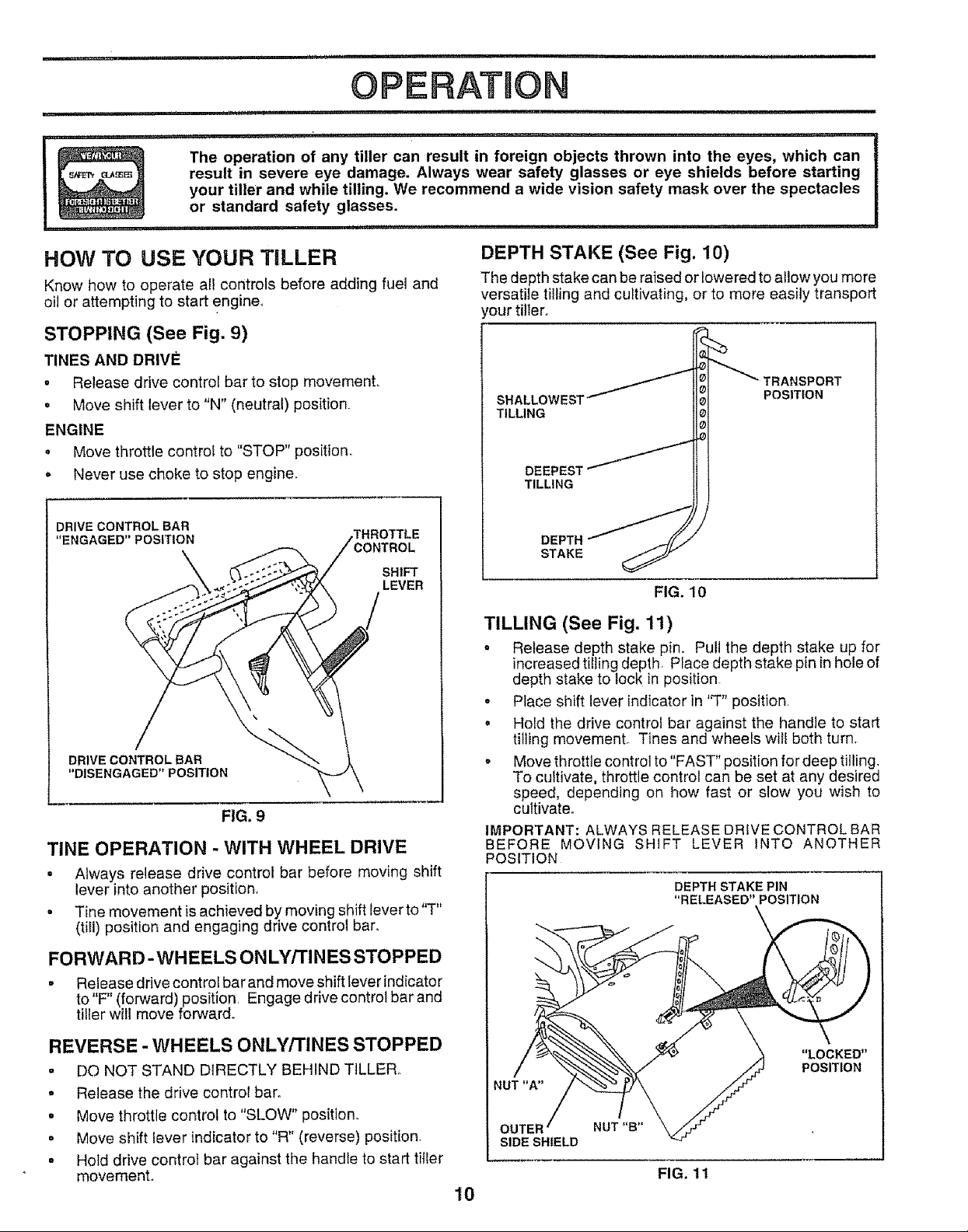
STOPPING (See Fig. 9)
TINES AND DRIVE
- Release drive control bar to stop movement.
o Move shift lever to "N" (neutral) position.
ENGINE
o Move throttle control to "STOP" position.
o Never use choke to stop engine_
DRIVE CONTROL BAR
"ENGAGED" POSITION
DRIVE CONTROL BAR
"DISENGAGED" POSITION
FIG. 9
TINE OPERATION - WITH WHEEL DRIVE
• Always release drive control bar before moving shift
lever into another position.
• ..... r "T"
Tine movement ts achieved by mowng shift leve to
(till) position and engaging drive control bar.
.THROTTLE
SHIFT
LEVER
DEPTH STAKE (See Fig. 10)
The depth stake can be raised or lowered to allow you more
versatile tilling and cultivating, or to more easily transport
'our tiller°
SHALLOWES=I
TILLING
TILLING
POSITION
TILLING (See Fig, 11)
o Release depth stake pin. Pull the depth stake up for
increased tilling depth. Place depth stake pin inhole of
depth stake to lock in position
. Place shift lever indicator in 'q" position,
o Hold the drive control bar against the handle to start
tilling movemenL Tines and wheels will both turn,
- Move throttle control to "FAST" position for deep tilling.
To cultivate, throttle control can be set at any desired
speed, depending on how fast or slow you wish to
cultivate.
IMPORTANT: ALWAYS RELEASE DRIVE CONTROL BAR
BEFORE MOVING SHIFT LEVER INTO ANOTHER
POSITION
DEPTH STAKE PIN
"RELEASED" POSITION
\
FORWARD- WHEELS ON LY/TINES STOPPED
• Release drive control bar and move shift lever indicator
to "F" (forward)position Engage drive control bar and
tiller will move forward.,
REVERSE - WHEELS ONLY/TINES STOPPED
= DO NOT STAND DIRECTLY BEHIND TILLER.,
° Release the drive control bar.
° Move throttle control to "SLOW" position.
• Move shift lever indicator to "R" (reverse) position.
= Hold drive control bar against the handle to start tifier
movement.
"LOCKED"
POSITION
NUT "A"
OUTER NUT "B"
SIDE SHIELD
FIG. 11
10
 Loading...