

Craftsman 917291481 Owner’s Manual
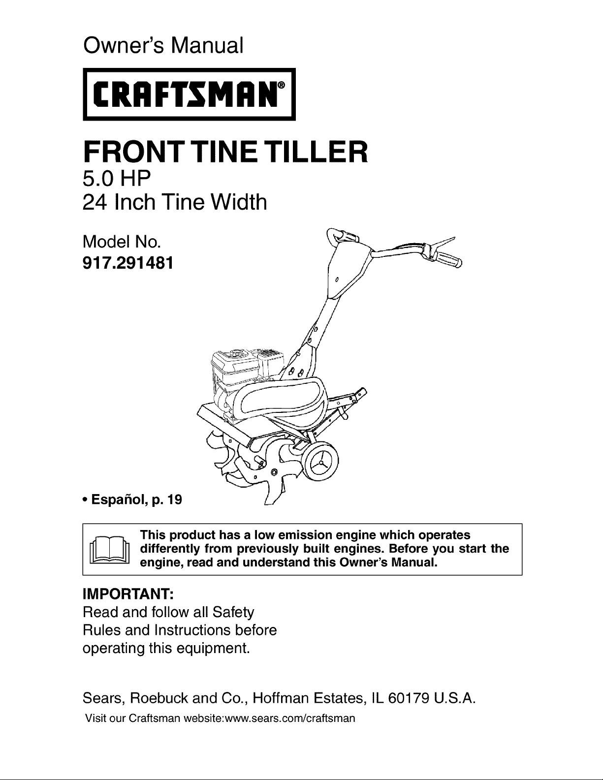
Owner's Manual
(RRFTSMRN°
FRONT TINE TIL LER
5.0 HP
24 Inch Tine Width
917.291481
Model No. "_
0
i¢
• Espahol, p. 19
This product has a low emission engine which operates
differently from previously built engines. Before you start the
engine, read and understand this Owner's Manual.
IMPORTANT:
Read and follow all Safety
Rules and Instructionsbefore
operating this equipment.
Sears, Roebuck and Co., Hoffman Estates, IL 60179 U.S.A.
Visit our Craftsman website:www.sears.com/craftsman

Warranty................................................2
SafetyRules..........................................2
ProductSpecifications...........................4
Assembly/Pre-Operation.......................5
Operation...............................................7
MaintenanceSchedule........................11
Manintenance......................................11
ServiceandAdjustments.....................14
Storage................................................16
Troubleshooting...................................17
IllustratedPartsList.............................36
SearsService........................BackCover
LIMITEDONEYEARWARRANTYON CRAFTSMANTILLER
Forone (1)yearfromdateof purchase,whenthis CraftsmanTiller ismaintained,
lubricated,andtuned upaccordingto the operatingandmaintenanceinstructionsinthe
owner'smanual,Searswillrepairfreeofcharge anydefectin materialorworkmanship.
ThisWarrantydoesnotcover:
• Expendableitemswhich becomeworn during normaluse,such astines,sparkplugs,
air cleanersandbelts.
• Repairsnecessarybecauseof operatorabuseor negligence,includingbentcrank-
shaftsandthe failureto maintainthe equipmentaccordingto the instructionscon-
tainedintheowner'smanual.
• Ifthis CraftsmanTiller isusedfor commercialor rentalpurposes,thisWarrantyap-
pliesfor onlythirty (30)daysfrom the date of purchase.
Warrantyserviceis availablebyreturningthe craftsmanpowermowerto thenearest
searsservicecenter/departmentinthe unitedstates.This warrantyappliesonly while
this productis in use inthe unitedstates.
ThisWarrantygivesyouspecificlegalrights,andyou mayalsohaveother rightswhich
varyfromstateto state.
SEARS,ROEBUCKAND CO.,D/817WA,HOFFMANESTATES,IL 60179 U.S.A.
IMPORTANT:This cuttingmachineis capableof amputatinghandsandfeet andthrow-
ingobjects.Failureto observethefollowingsafetyinstructionscouldresultin serious
injuryor death.
TRAINING
• Read the Owner's Manual carefully. Be
thoroughly familiar with the controls and
the proper use of the equipment. Know
how to stop the unit and disengage the
controls quickly.
• Never allow children to operate the
equipment. Never allow adults to op-
erate the equipment without proper
instruction.
• Keep the area of operation clear of all
persons, particularly small children, and
pets.
PREPARATION
• Thoroughly inspect the area where the
equipment is to be used and remove all
foreign objects.
• Disengage all clutches and shift into
neutral before starting the engine (mo-
tor).
• Do not operate the equipment without
wearing adequate outer garments. Wear
footwear that will improve footing on
slippery surfaces.
• Handle fuel with care; it is highly flam-
mable.
• Use an approved fuel container.
• Never add fuel to a running engine or
hot engine.
• Fill fuel tank outdoors with extreme care.
Never fill fuel tank indoors.
• Replace gasoline cap securely and
clean up spilled fuel before restarting.
2
• Use extension cords and receptacles
as specified by the manufacturer for all
units with electric drive motors or elec-
tric starting motors.
• Never attempt to make any adjustments
while the engine (motor) is running (ex-
cept where specifically recommended
by manufacturer).
OPERATION
• Do not put hands or feet near or under
rotating parts.
• Exercise extreme caution when operat-
ing on or crossing gravel drives, walks,
or roads. Stay alert for hidden hazards
or traffic. Do not carry passengers.
• After striking a foreign object, stop the
engine (motor), remove the wire from
the spark plug, thoroughly inspect the
tiller for any damage, and repair the
damage before restarting and operating
the tiller.
• Exercise caution to avoid slipping or fall-
ing.
• If the unit should start to vibrate ab-
normally, stop the engine (motor) and
check immediately for the cause. Vibra-
tion is generally a warning of trouble.
• Stop the engine (motor) when leaving
the operating position.
• Take all possible precautions when leav-
ing the machine unattended. Disengage
the tines, shift into neutral, and stop the
engine.
• Before cleaning, repairing, or inspecting,
shut off the engine and make certain all
moving parts have stopped. Disconnect
the spark plug wire, and keep the wire
away from the plug to prevent accidental
starting. Disconnect the cord on electric
motors.
• Do not run the engine indoors; exhaust
fumes are dangerous.
• Never operate the tiller without proper
guards, plates, or other safety protective
devices in place.
• Keep children and pets away.
• Do not overload the machine capacity
by attempting to till too deep at too fast
a rate.
• Never operate the machine at high
speeds on slippery surfaces. Look be-
hind and use care when backing.
• Never allow bystanders near the unit.
• Use only attachments and accessories
approved by the manufacturer of the
tiller.
• Never operate the tiller without good vis-
ibility or light.
• Be careful when tilling in hard ground.
The tines may catch in the ground and
propel the tiller forward. If this occurs,
let go of the handlebars and do not
restrain the machine.
MAINTENANCE AND STORAGE
• Keep machine, attachments, and ac-
cessories in safe working condition.
• Check shear pins, engine mounting
bolts, and other bolts at frequent inter-
vals for proper tightness to be sure the
equipment is in safe working condition.
• Never store the machine with fuel in the
fuel tank inside a building where ignition
sources are present, such as hot water
and space heaters, clothes dryers, and
the like. Allow the engine to cool before
storing in any enclosure.
• Always refer to the operator's guide
instructions for important details if the
tiller is to be stored for an extended
period.
_Look for this symbol to point out
important safety precautions. It means
CAUTION!!! BECOME ALERT!!! YOUR
SAFETY IS INVOLVED.
_CAUTION: Always disconnect spark
plug wire and place wire where it cannot
contact spark plug in order to prevent acci-
dental starting when setting up, transport-
ing, adjusting or making repairs.
_WARNING: Engine exhaust, some of its
constituents, and certain vehicle compo-
nents contain or emit chemicals known to
the State of California to cause cancer and
birth defects or other reproductive harm.
3
PRODUCT SPECIFICATIONS
Gasoline 3 Qts
Capacity: Unleaded Regular
OiI(API-SF-SJ): SAE 30
(Capacity: 20 oz.) (Above 32°F)
SAE 5w-30
(Below 32°F)
Spark Plug : Champion
(Gap: .030") RC12YC
CONGRATULATIONS on your purchase
of a Sears Tiller. It has been designed,
engineered and manufactured to give you
the best possible dependability and per-
formance.
Should you experience any problems you
cannot easily remedy, please contact a
Sears or other qualified Service Center.
We have competent, well-trained techni-
cians and the proper tools to service or
repair this unit.
Please read and retain this manual. The
instructions will enable you to assemble
and maintain your tiller properly. Always
observe the "SAFETY RULES".
Your new tiller has been assembled at the
factory with exception of those parts left
unassembled for shipping purposes. To
ensure safe and proper operation of your
tiller all parts and hardware you assemble
must be tightened securely. Use the cor-
rect tools as necessary to insure proper
tightness.
CUSTOMER RESPONSIBILITIES
• Read and observe the safety rules.
• Follow a regular schedule in main-
taining, caring for and using your tiller.
• Follow the instructions under the "Main-
tenance" and "Storage" sections of this
Owner's Manual.
_WARNING: This unit is equipped with
an internal combustion engine and should
not be used on or near any unimproved
forest-covered, brush-covered or grass
covered land unless the engine's exhaust
system is equipped with a spark arrester
meeting applicable local or state laws (if
any). If a spark arrester is used, it should
be maintained in effective working order
by the operator.
In the state of California the above is
required by law (Section 4442 of the
California Public Resources Code). Other
states may have similar laws. Federal
laws apply on federal lands. A spark ar-
rester for the muffler is available through
your nearest Sears service center (See
REPAIR PARTS section of this manual).
REPAIR PROTECTION
AGREEMENTS
Congratulations on making a smart pur-
chase. Your new Craftsman® product is
designed and manufactured for years of
dependable operation. But like all products,
it may require repair from time to time. That's
when having a Repair Protection Agreement
can save you money and aggravation.
Purchase a Repair Protection Agreement
now and protect yourself from unexpected
hassle and expense,
Here's what's included in the Agreement:
• Expert service by our 12,000 profe-
sional repair specialists.
• Unlimited service and no charge for
parts and labor on all covered repairs.
• Product replacement if your covered
product can't be fixed.
• Discount of 10% from regular price of
service and service-related parts not
covered by the agreement; also, 10%
off regular price of preventive mainte-
nance check.
• Fast help by phone - phone support
from a Sears technician on products
requiring in-home repair, plus conve-
nient repair scheduling.
Once you purchase the Agreement, a
simple phone call is all that it takes for you
to schedule service. You can call anytime
day or night, or schedule a service ap-
pointment online.
Sears has over 12,000 professional repair
specialists, who have access to over 4.5
million quality parts and accessories.
That's the kind of professionalism you can
count on to help prolong the life of your
new purchase for years to come. Purchase
your Repair Protection Agreement today!
Some limitations and exclusions apply.
For prices and additional information
call 1-800-827-6655.
SEARS INSTALLATION SERVICE
For Sears professiona/ insta//ation of home
appliances, garage door openers, water
heaters, and other major home items, in
the U.S.A. call 1-800-4-MY-HOME®
4
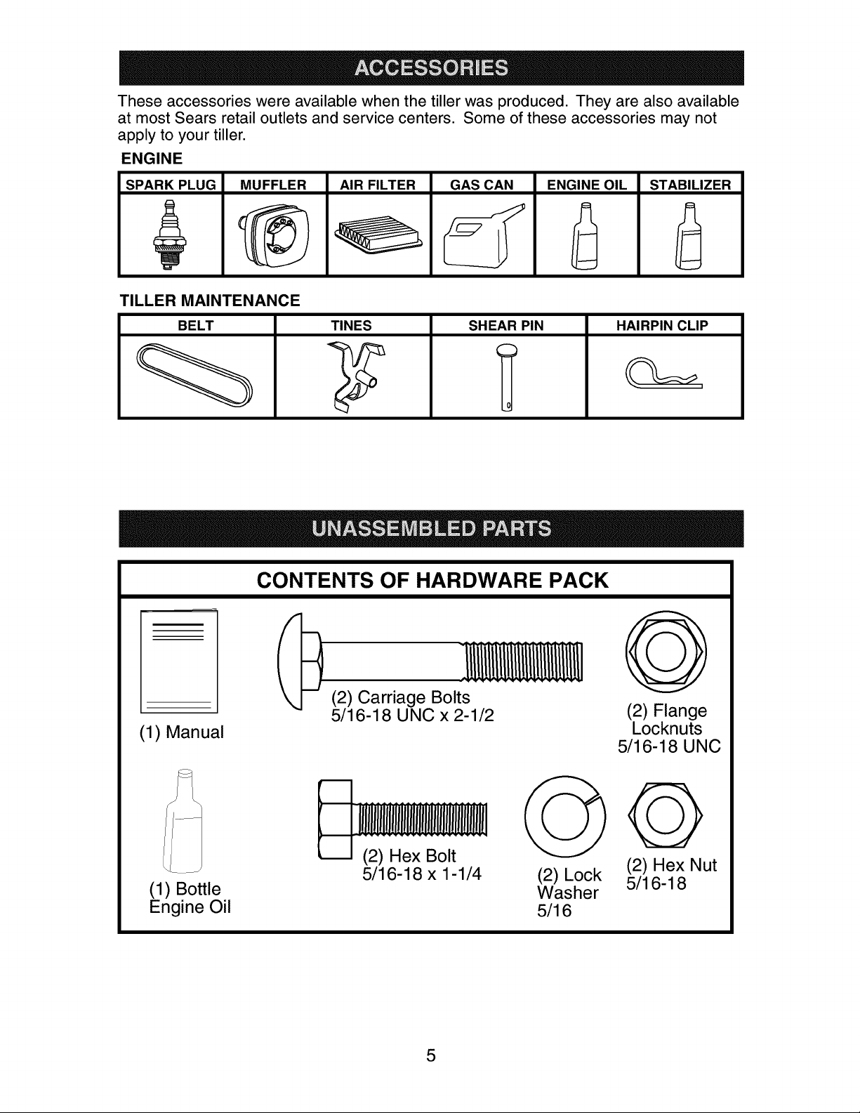
These accessories were available when the tiller was produced. They are also available
at most Sears retail outlets and service centers. Some of these accessories may not
apply to your tiller.
ENGINE
SPARK PLUG MUFFLER AIR FILTER GAS CAN ENGINE OILASTABILIZER
TILLER MAINTENANCE
BELT TINES SHEAR PIN
CONTENTS OF HARDWARE PACK
(2) Carriage Bolts
5/16-18 UNC x 2-1/2
(1) Manual
HAIRPIN CLIP
O
G
(2) Flange
Locknuts
5/16-18 UNC
(1) Bottle
Engine Oil
(2) Hex Bolt
5/16-18 x 1-1/4
(2) Lock
Washer
5/16
Q
(2) Hex Nut
5/16-18
Yournew tillerhas beenassembledatthe factorywiththe exceptionof thosepartsleft
unassembledforshippingpurposes.Toensuresafe andproperoperationof yourtiller
allparts and hardwareyou assemblemust betightenedsecurely. Usethe correcttools
asnecessaryto insurepropertightness.
TOOLS REQUIRED FOR
ASSEMBLY
A socket wrench set will make assembly
easier. Standard wrench sizes are listed.
(1) Utility knife
(2) 1/2 Wrench
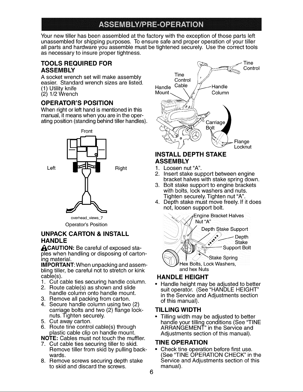
OPERATOR'S POSITION
When right or left hand is mentioned in this
manual, it means when you are in the oper-
ating position (standing behind tiller handles).
Front
Left
overhead_views_7
Operator's Position
UNPACK CARTON & INSTALL
HANDLE
_CAUTION: Be careful of exposed sta-
ples when handling or disposing of carton-
ing material.
IMPORTANT: When unpacking and assem-
bling tiller, be careful not to stretch or kink
cable(s).
1. Cut cable ties securing handle column.
2. Route cable(s) as shown and slide
handle column onto handle mount.
3. Remove all packing from carton.
4. Secure handle column using two (2)
carriage bolts and two (2) flange lock-
nuts. Tighten securely.
5. Cut away carton.
6. Route tine control cable(s) through
plastic cable clip on handle mount.
NOTE: Cables must not touch the muffler.
7. Cut cable ties securing tiller to skid.
Remove tiller from skid by pulling back-
wards.
8. Remove screws securing depth stake
to skid and discard the screws.
Right
Tine
Control
Tine (_/_/ __
Control j_i
Handle Cable //.11 Handle
Moun_ k_i/- Column
_/._ <_CarriageJ
_ _o_v_. ___.) _.- Flange
/__/ _ Locknut
INSTALL DEPTH STAKE
ASSEMBLY
1. Loosen nut"A".
2. Insert stake support between engine
bracket halves with stake spring down.
3. Bolt stake support to engine brackets
with bolts, lock washers and nuts.
Tighten securely. Tighten nut "A".
4. Depth stake must move freely. If it does
not, loosen support bolt.
ine Bracket Halves
"A"
Stake Support
Stake
pport Bolt
Spring
Hex Bolts, Lock Washers,
and hex Nuts
HANDLE HEIGHT
• Handle height may be adjusted to better
suit operator. (See "HANDLE HEIGHT"
in the Service and Adjustments section
of this manual).
TILLING WIDTH
• Tilling width may be adjusted to better
handle your tilling conditions (See "TINE
ARRANGEMENT" in the Service and
Adjustments section of this manual).
TINE OPERATION
• Check tine operation before first use.
(See "TINE OPERATION CHECK" in the
Service and Adjustments section of this
manual).
6
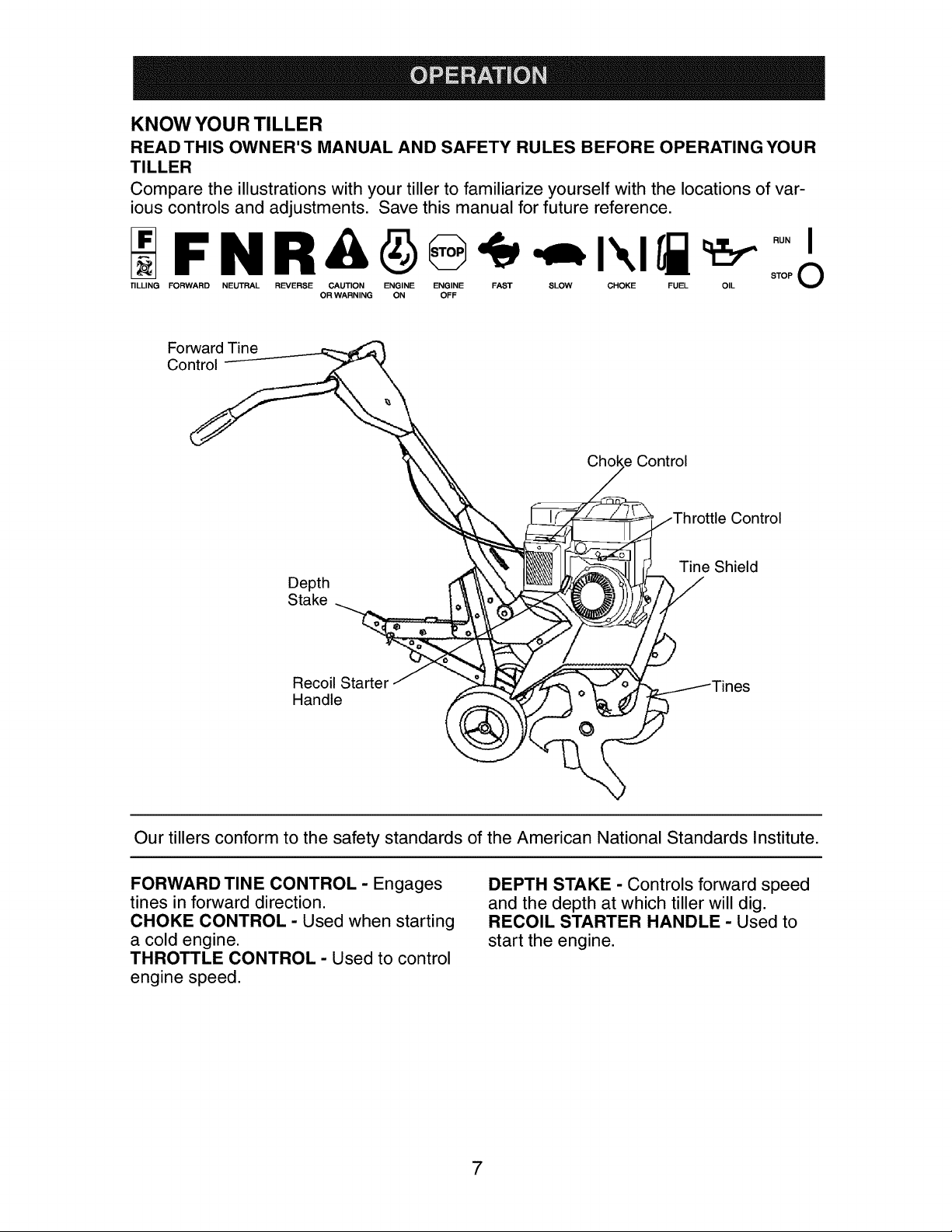
KNOW YOUR TILLER
READTHIS OWNER'S MANUAL AND SAFETY RULES BEFORE OPERATING YOUR
TILLER
Compare the illustrations with your tiller to familiarize yourself with the locations of var-
ious controls and adjustments. Save this manual for future reference.
FNRA O -,=I I
rlLLING FORWARD NEUTRAL REVERSE CAUTION ENGINE ENGINE FAST SLOW CHOKE FUEL OIL STOP V
Forward Tine
OR WARNING ON OFF
Our tillers conform to the safety standards of the American National Standards Institute.
FORWARD TINE CONTROL - Engages
tines in forward direction.
CHOKE CONTROL - Used when starting
a cold engine.
THROTTLE CONTROL - Used to control
engine speed.
DEPTH STAKE - Controls forward speed
and the depth at which tiller will dig.
RECOIL STARTER HANDLE - Used to
start the engine.
Theoperationofanytiller canresultinforeignobjectsthrownintotheeyes,
whichcan resultin severeeyedamage. Alwayswearsafety glassesor eye
shieldsbeforestartingyourtillerandwhiletilling. Werecommendstandard
safetyglassesor awidevisionsafetymaskwornoverspectacles.
HOW TO USE YOUR TILLER
Know how to operate all controls before
adding fuel and oil or attempting to start
engine.
STOPPING
TINES
• Release tine control to stop movement.
ENGINE
• Move throttle control to "STOP" position.
NOTE: Never use choke to stop engine.
Tine Control
"Off" (UP) Position
Tine Control
"On" (DOWN) Position
Control
Choke
Control
TINE OPERATION
• Squeeze tine controlto handle.
TILLING
The speed and depth of tilling is regulated
by the position of the depth stake and
wheel height.
The depth stake should always be below
the wheels for digging. It serves as a
brake to slow the tiller's forward motion to
enable the tines to penetrate the ground.
Also, the more the depth stake is lowered
into the ground the deeper the tines will
dig.
DEPTH STAKE
Adjust depth stake by removing the hairpin
clip and clevis pin. Change depth stake
to desired position. Replace the clevis pin
and hairpin clip.
• For normal tilling, set depth stake at the
second or third hole from the top.
WHEELS
Adjust wheels by removing the hairpin clip
and clevis pin. Change wheel position.
Replace the hairpin clip and clevis pin.
• For normal tilling, set wheels at the
second or third hole from the top.
Hairpin Clip and
Clevis Pin
Depth
Stake
Wheel Spring
TO TRANSPORT
_CAUTION: Before lifting or transporting,
allow tiller engine and muffler to cool. Dis-
connect spark plug wire. Drain gasoline
from fuel tank.
AROUND THE YARD
1. Tip depth stake forward until it is held
by the stake spring.
2. Push tiller handles down, raising tines
off the ground.
3. Push or pull tiller to desired location.
AROUND TOWN
1. Disconnect spark plug wire.
2. Drain fuel tank.
3. Transport in upright position to prevent
oil leakage.
BEFORE STARTING ENGINE
IMPORTANT: Be very careful not to allow
dirt to enter the engine when checking or
adding oil or fuel. Use clean oil and fuel
and store in approved, clean, covered
containers, use clean fill funnels.
FILL ENGINE WITH OIL
1. Remove hangtag from engine.
2. With engine level, remove engine oil
filler plug.
3. Fill engine with oil to point of over-
flowing. For approximate capacity see
"PRODUCT SPECIFICATIONS" on
page 4 of this manual. All oil must meet
A.P.I. Service Classification SF-SJ.
8
4. Tilt tiller back on its wheels and then
re-level.
5. With engine level, refill to point of over-
flowing if necessary. Replace oil filler
plug.
• For cold weather operation you should
change oil for easier starting (See "OIL
VISCOSITY CHART" in the Mainte-
nance section of this manual).
• To change engine oil, see the Mainte-
nance section of this manual.
Oil Filler
Oil Level Plug
ADD GASOLINE
• Fill fuel tank to bottom of filler neck. Do
not overfill. Use fresh, clean, regular
unleaded gasoline with a minimum of
87 octane. (Use of leaded gasoline will
increase carbon and lead oxide depos-
its and reduce valve life). Do not mix oil
with gasoline. Purchase fuel in quan-
tities that can be used within 30 days to
assure fuel freshness.
_I_CAUTION: Fill to within 1/2 inch of top
of fuel tank to prevent spills and to allow
for fuel expansion. If gasoline is acci-
dentally spilled, move machine away from
area of spill. Avoid creating any source of
ignition until gasoline vapors have disap-
peared.
Wipe off any spilled oil or fuel. Do not
store, spill or use gasoline near an open
flame.
IMPORTANT: When operating in temper-
atures below32°F(0°C), use fresh, clean
winter grade gasoline to help insure good
cold weather starting.
CAUTION: Alcohol blended fuels (called
gasohol or using ethanol or methanol) can
attract moisture which leads to separa-
tion and formation of acids during storage.
Acidic gas can damage the fuel system
of an engine while in storage. To avoid
engine problems, the fuel system should
be emptied before storage of 30 days
or longer. Drain the gas tank, start the
engine and let it run until the fuel lines
and carburetor are empty. Use fresh fuel
next season. See Storage Instructions for
additional information. Never use engine
or carburetor cleaner products in the fuel
tank or permanent damage may occur.
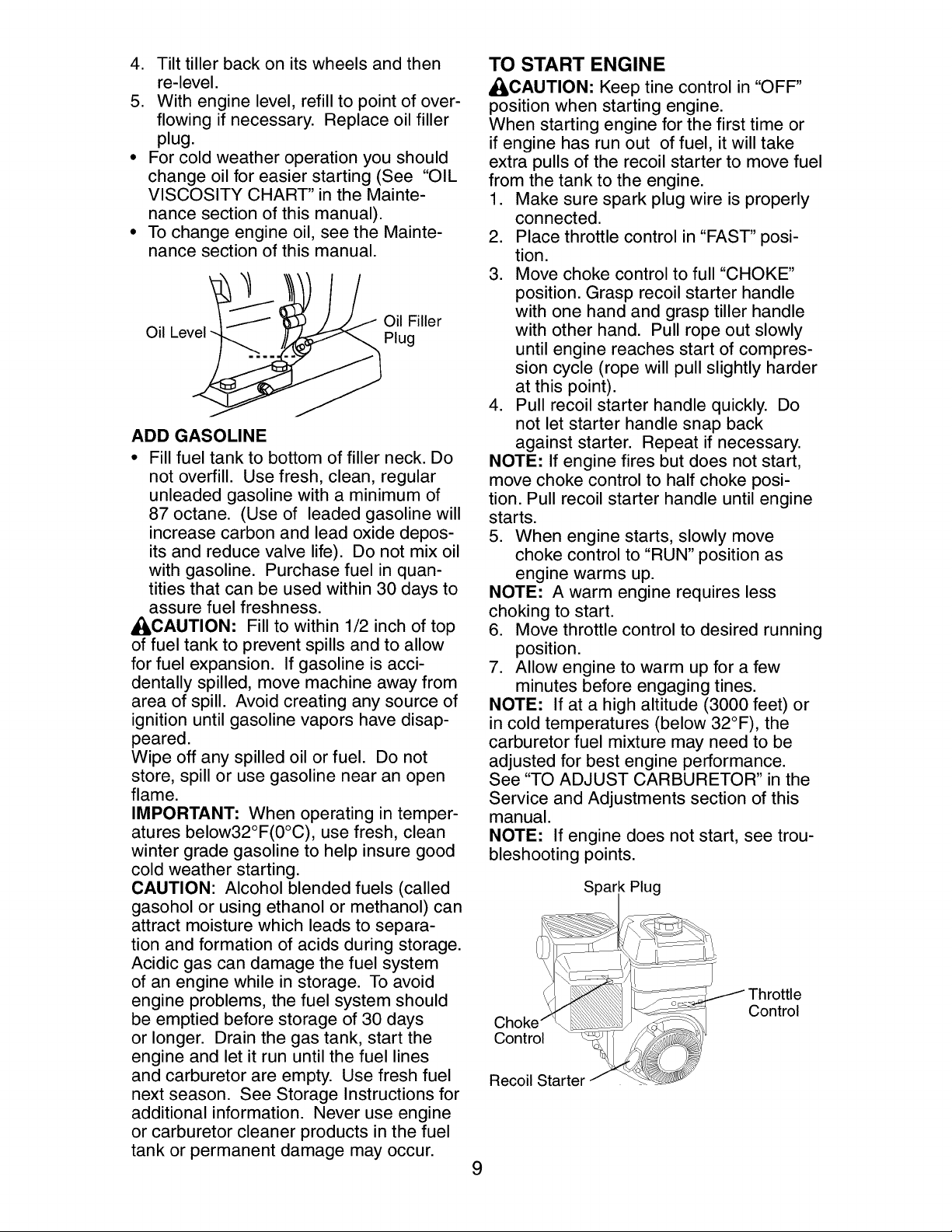
TO START ENGINE
_CAUTION: Keep tine control in "OFF"
position when starting engine.
When starting engine for the first time or
if engine has run out of fuel, it will take
extra pulls of the recoil starter to move fuel
from the tank to the engine.
1. Make sure spark plug wire is properly
connected.
2. Place throttle control in "FAST" posi-
tion.
3. Move choke control to full "CHOKE"
position. Grasp recoil starter handle
with one hand and grasp tiller handle
with other hand. Pull rope out slowly
until engine reaches start of compres-
sion cycle (rope will pull slightly harder
at this point).
4. Pull recoil starter handle quickly. Do
not let starter handle snap back
against starter. Repeat if necessary.
NOTE: If engine fires but does not start,
move choke control to half choke posi-
tion. Pull recoil starter handle until engine
starts.
5. When engine starts, slowly move
choke control to "RUN" position as
engine warms up.
NOTE: A warm engine requires less
choking to start.
6. Move throttle control to desired running
position.
7. Allow engine to warm up for a few
minutes before engaging tines.
NOTE: If at a high altitude (3000 feet) or
in cold temperatures (below 32°F), the
carburetor fuel mixture may need to be
adjusted for best engine performance.
See "TO ADJUST CARBURETOR" in the
Service and Adjustments section of this
manual.
NOTE: If engine does not start, see trou-
bleshooting points.
Spar Plug
Control
Control
Recoil Starter
9
BREAKING IN YOUR TILLER
Break-in your belt(s), pulleys and tine con-
trol before you actually begin tilling.
• Start engine, tip tines off ground by
pressing handles down and engage tine
control to start tine rotation. Allow tines
to rotate for five minutes.
• Check tine operation and adjust if
necessary. See 'q-INE OPERATION
CHECK" in the Service and Adjustments
section of this manual.
TILLING HINTS
_CAUTION: Until you are accustomed to
handling your tiller, start actual field use
with throttle in slow position.
To help tiller move forward, lift up the
handles slightly (thus lifting depth stake
out of ground). To slow down the tiller,
press down on handles.
If you are straining or tiller is shaking,
the wheels and depth stake are not set
properly in the soil being tilled. The proper
setting of the wheels and depth stake is
through trial and error and depends upon
the soil condition. (The harder or wetter
the ground, the slower the engine and tine
speed needed. Under these poor condi-
tions, at fast speed the tiller will run and
jump over the ground).
A properly adjusted tiller will dig with little
effort from the operator.
• Tilling is digging into, turning over, and
breaking up packed soil before planting.
Loose, unpacked soil helps root growth.
Best tilling depth is 4"-6". A tiller will
also clear the soil of unwanted vegeta-
tion. The decomposition of this vegeta-
ble matter enriches the soil. Depending
on the climate (rainfall and wind), it may
be advisable to till the soil at the end of
the growing season to further condition
the soil.
• Soil conditions are important for proper
tilling. Tines will not readily penetrate
dry, hard soil which may contribute to
excessive bounce and difficult handling
of your tiller. Hard soil should be mois-
tened before tilling; however, extremely
wet soil will "ball-up" or clump during till-
ing. Wait until the soil is less wet in order
to achieve the best results. When tilling
in the fall, remove vines and long grass
to prevent them from wrapping around
the tine shaft and slowing your tilling
operation.
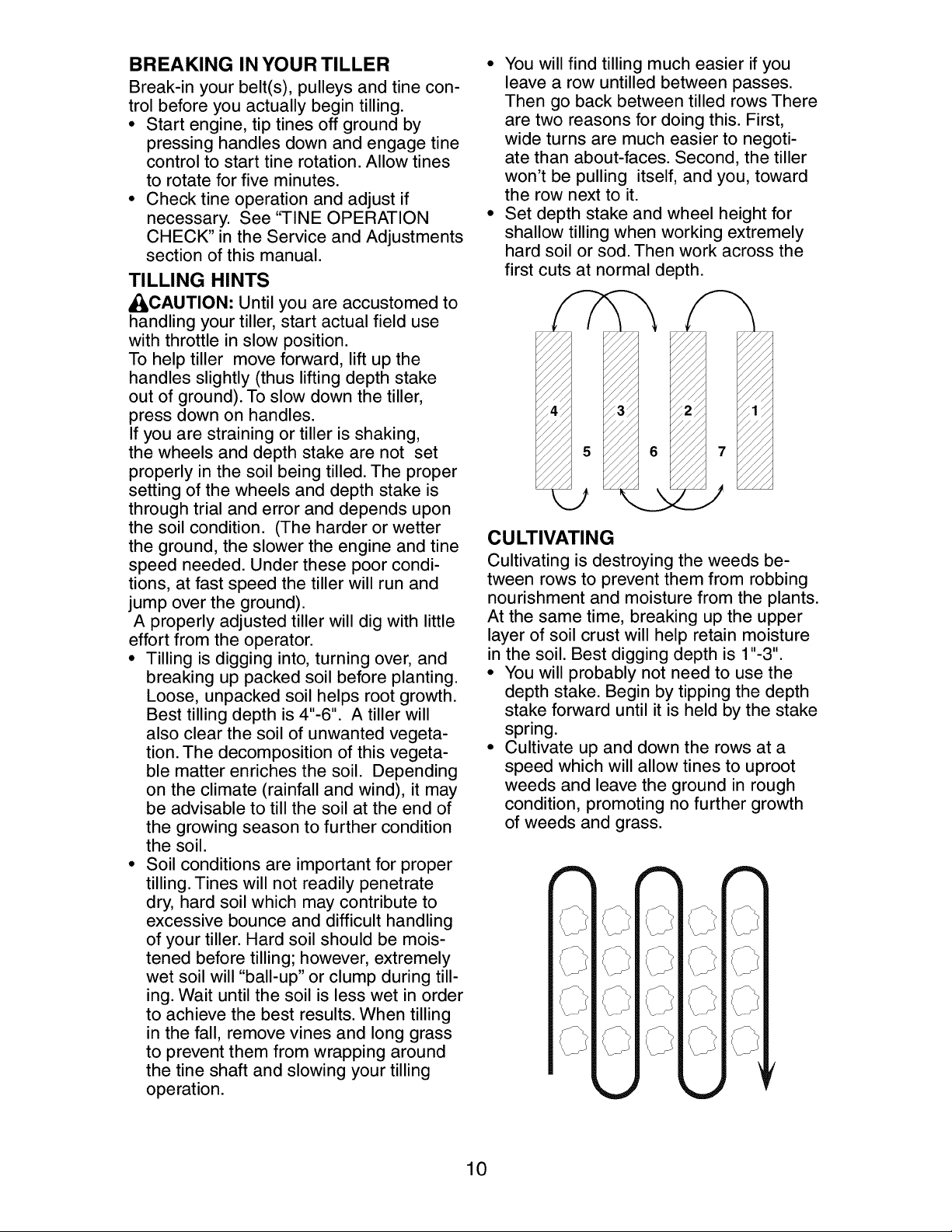
• You will find tilling much easier if you
leave a row untilled between passes.
Then go back between tilled rows There
are two reasons for doing this. First,
wide turns are much easier to negoti-
ate than about-faces. Second, the tiller
won't be pulling itself, and you, toward
the row next to it.
• Set depth stake and wheel height for
shallow tilling when working extremely
hard soil or sod. Then work across the
first cuts at normal depth.
CULTIVATING
Cultivating is destroying the weeds be-
tween rows to prevent them from robbing
nourishment and moisture from the plants.
At the same time, breaking up the upper
layer of soil crust will help retain moisture
in the soil. Best digging depth is 1"-3".
• You will probably not need to use the
depth stake. Begin by tipping the depth
stake forward until it is held by the stake
spring.
• Cultivate up and down the rows at a
speed which will allow tines to uproot
weeds and leave the ground in rough
condition, promoting no further growth
of weeds and grass.
s\
f\ f\
10
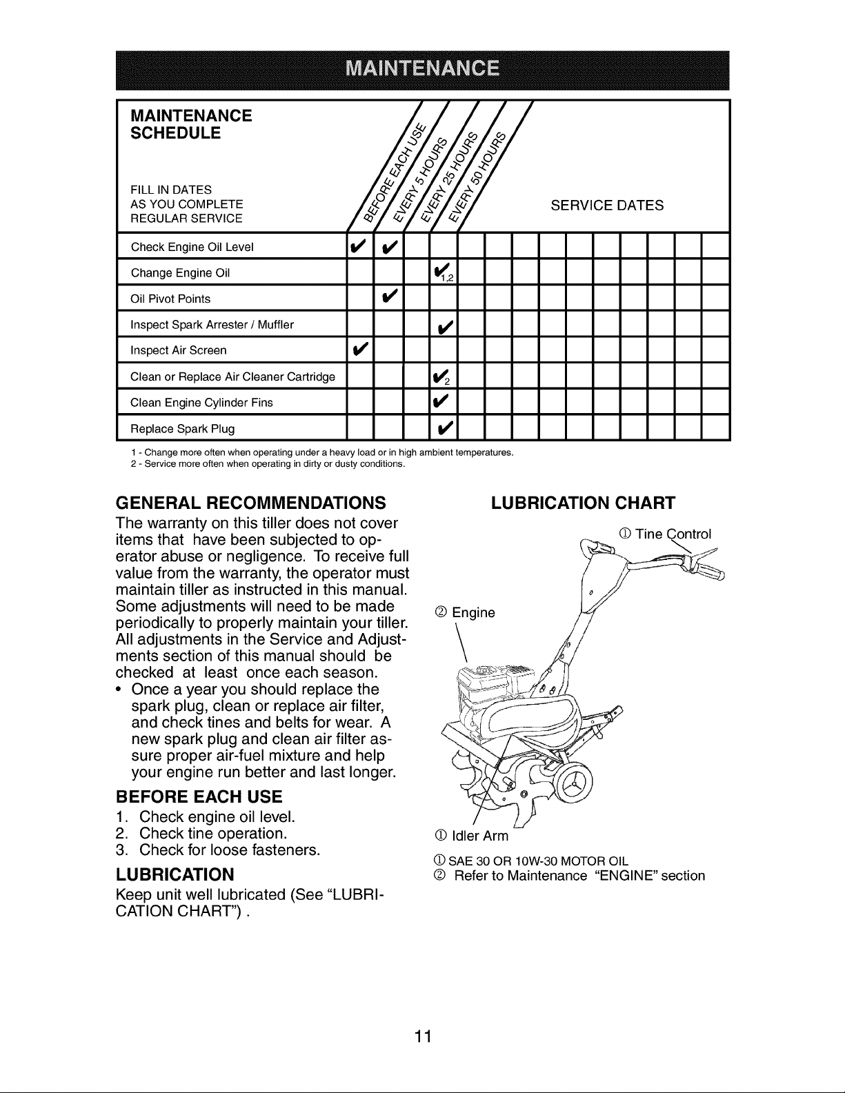
MAINTENANCE
SCHEDULE
FILL IN DATES
AS YOU COMPLETE
REGULAR SERVICE
XZ/J/
SERVICE DATES
Check Engine Oil Level
Change Engine Oil I_'1,2
Oil Pivot Points I_'
Inspect Spark Arrester / Muffler I_
Inspect Air Screen V'
Clean or Replace Air Cleaner Cartridge 1_2
Clean Engine Cylinder Fins V'
Replace Spark Plug V'
1 - Change more often when operating under a heavy load or in high ambient temperatures.
2 - Service more often when operating in dirty or dusty conditions.
tl ol
GENERAL RECOMMENDATIONS
The warranty on this tiller does not cover
items that have been subjected to op-
erator abuse or negligence. To receive full
value from the warranty, the operator must
maintain tiller as instructed in this manual.
Some adjustments will need to be made
periodically to properly maintain your tiller.
All adjustments in the Service and Adjust-
ments section of this manual should be
checked at least once each season.
• Once a year you should replace the
spark plug, clean or replace air filter,
and check tines and belts for wear. A
new spark plug and clean air filter as-
sure proper air-fuel mixture and help
your engine run better and last longer.
BEFORE EACH USE
1. Check engine oil level.
2. Checktine operation.
3. Check for loose fasteners.
LUBRICATION
Keep unit well lubricated (See "LUBRI-
CATION CHART").
o 0in;
0 Idler Arm
Q SAE30 OR 10W-30 MOTOROIL
® Refer to Maintenance "ENGINE" section
LUBRICATION CHART
O Tine Control
11
_ILCAUTION: Disconnect spark plug
wire before performing any maintenance
(except carburetor adjustment) to prevent
accidental starting of engine.
Prevent fires! Keep the engine free of
grass, leaves, spilled oil, or fuel. Remove
fuel from tank before tipping unit for main-
tenance. Clean muffler area of all grass,
dirt, and debris.
Do not touch hot muffler or cylinder fins as
contact may cause burns.
ENGINE
LUBRICATION
Use only high quality detergent oil rated
with API service classification SF-SJ.
Select the oil's SAE viscosity grade ac-
cording to your expected temperature.
SAE VISCOSITY GRADES
F _20 0 3o 3240 60 80 ,08
c -_0 -2'8 -1_ _ ,'0 _8 _0 4'0
TEMPERATURE RANGE ANTICIPATED BEFORE NEXT OIL CHANGE
oil visc chartl_
NOTE: Although multi-viscosity oils
(5W-30, 10W-30, etc.)improve starting
in cold weather, these multi-viscosity oils
will result in increased oil consumption
when used above 32°F (0°C). Check your
engine oil level more frequently to avoid
possible engine damage from running low
on oil.
Change the oil after every 50 hours of
operation or at least once a year if the tiller
is not used for 50 hours in one year.
Check the crankcase oil level before
starting the engine and after each five (5)
hours of continuous use. Add SAE 30 mo-
tor oil or equivalent. Tighten oil filler plug
securely each time you check the oil level.
5. Refill engine with oil. See "FILL
ENGINE WITH OIL" in the Operation
section of this manual.
Oil
Drain
Plug,,_
Oil Level
Oil Filler Plug
AIR CLEANER
Service air cleaner cartridge every
twenty-five hours, more often if engine is
used in very dusty conditions.
1. Loosen air cleaner screw.
2. Remove air cleaner cover.
3. Carefully remove air cleaner cartridge.
Be careful. Do not allow dirt or debris
to fall into carburetor.
4. Clean by tapping gently on a flat sur-
face.
NOTE: If very dirty or damaged, replace
cartridge.
5. Clean and replace cover. Tighten
screw securely.
_CAUTION: Petroleum solvents, such
as kerosene, are not to be used to clean
cartridge. They may cause deterioration
of the cartridge. Do not oil cartridge. Do
not use pressurized air to clean or dry
cartridge.
Air Cleaner
Cartridge
Cover
TO CHANGE ENGINE OIL
Determine temperature range expected
before oil change. All oil must meet API
service classification SF-SJ.
• Be sure tiller is on level surface.
• Oil will drain more freely when warm.
• Catch oil in a suitable container.
1. Remove drain plug.
2. Tip tiller forward to drain oil.
3. After oil has drained completely,
replace oil drain plug and tighten se-
curely.
4. Remove oil filler plug. Be careful not to
allow dirt to enter the engine.
Air Cleane
Screw
12
COOLING SYSTEM
Your engine is air cooled. For proper en-
gine performance and long life keep your
engine clean.
• Clean air screen frequently using a
stiff-bristled brush.
• Remove blower housing and clean as
necessary.
• Keep cylinder fins free of dirt and chaff.
Muffler
Cylir
\
MUFFLER
Do not operate tiller without muffler. Do
not tamper with exhaust system. Dam-
aged mufflers or spark arresters could
create a fire hazard. Inspect periodically
and replace if necessary. If your engine is
equipped with a spark arrester screen as-
sembly, remove every 50 hours for clean-
ing and inspection. Replace if damaged.
Fins
Blower
_ Ho.using
Air Screen
SPARK PLUG
Replace spark plugs at the beginning of
each tilling season or after every 50 hours
of use, whichever comes first. Spark plug
type and gap setting are shown in "PROD-
UCT SPECIFICATIONS" on page 4 of this
manual.
TRANSMISSION
Your transmission is sealed and will not
require lubrication unless serviced.
CLEANING
Do not clean your tiller when the engine
and transmission are hot. We do not rec-
ommend using pressurized water (garden
hose, etc.) to clean your unit unless the
gasket area around the transmission and
the engine muffler, air filter and carburetor
are covered to keep water out. Water in
engine will shorten the useful life of your
tiller.
• Clean engine, wheels, finish, etc. of all
foreign matter.
• Keep finished surfaces and wheels free
of all gasoline, oil, etc.
• Protect painted surfaces with auto-
motive type wax.
13
_CAUTION: Disconnect spark plug wire
from spark plug and place wire where it
cannot come into contact with plug.
TILLER
MID-WIDTH TILLING - 22" PATH
• Assemble holes "A" in tine hubs to holes
"C" in tine shaft.
TO ADJUST HANDLE HEIGHT
Factory assembly has provided lowest
handle height. Select handle height best
suited for your tilling conditions. Handle
height will be different when tiller digs into
soil.
1. If a higher handle height is desired,
loosen the four nuts securing handle
panel to engine brackets.
2. Slide handle panel to desired location.
3. Tighten the four nuts securely.
Engine Brackets
Panel
Nuts(Also 2
on Left Side
of Tiller
TINE ARRANGEMENT
Your outer tines can be assembled in
several different ways to suit your tilling or
cultivating needs.
AI_CAUTION: Tines are sharp. Wear
gloves or other protection when handling
tines.
NORMAL TILLING - 24" PATH
• Assemble holes "A" in tine hubs to holes
"B" in tine shaft.
_-- Clevis Pin Outer Tine
__:_ _/_ilai!i_ oclip _lAnnerTine
Lo oJ
NAR ROW TI LLING/CU LTIVATI NG -
12-3/4" PATH
• Remove outer tines.
Inner Tines Only
NOTE: When reassembling outer tines,
be sure right tine assembly (marked "R")
and left tine assembly (marked "1") are
mounted to correct side of tine shaft.
TINE OPERATION CHECK
_WARNING: Disconnect spark plug wire
from spark plug to prevent starting while
checking tine operation.
For proper tine operation, tine control lever
must be against control body and all slack
removed from inner wire of control cable
when control is in the "OFF" (up) position.
If lever and cable are loose, loosen cable
clip at lower end of cable. Pull up on cable
to remove slack, without extending spring
on end of cable, and retighten cable clip.
FINAL CHECK "OFF" POSITION
1. With tine control "OFF" (up), push
down on handle to raise tines off the
ground.
2. Slowly pull recoil starter handle while
observing tines. Tines should not
rotate.
3. If tines rotate, inner wire of control
cable is too tight which is extend-
ing lower spring and engaging tines.
Loosen cable clip and push down on
cable only enough to relieve spring ten-
sion. Tighten cable clip.
4. Recheck in "OFF" position and adjust
if necessary.
14
FINAL CHECK "ON" POSITION
5. With tine control "ON" (held down to
handle) push down on handle to raise
tines off the ground.
6. Slowly pull recoil starter handle while
observing tines. Tines should rotate
forward.
7. If tines do not rotate, inner wire of con-
trol cable is too loose. Loosen cable
clip and pull cable up to remove slack
and retighten clip.
8. Recheck in "ON" position and adjust if
necessary.
NOTE: If "ON" position check required
adjustment, recheck "OFF" position ad-
justment to insure tines do not rotate when
control is "OFF" (up).
Tine Control "OFF" Position
TO REPLACE V-BELT
Replace V-belt if it has stretched consid-
erably or if it has cracks or frayed edges.
1. Belt guard must be removed to ser-
vice belt. See "TO REMOVE BELT
GUARD" in this section of manual.
BELT REMOVAL
2. Remove V-belt from transmission pul-
ley first and then from engine pulley.
BELT REPLACEMENT
3. Install new V-belt to engine pulley first
then to transmission pulley. Be sure
belt is positioned on inside groove of
both pulleys, inside all belt guides and
rests on idler pulley.
CHECK TINE OPERATION
4. See "TINE OPERATION CHECK" in
this section of manual.
5. Replace belt guard
Belt Guide t _J/L
Tine Control "ON" Position
Tine Control Cable
TO REMOVE BELT GUARD
1. Remove screws from side of belt
guard.
2. Pull belt guard out and away from unit.
3. Replace belt guard by reversing above
procedure. Be sure slot in bottom of
belt guard is under head of tine shield
bolt and all nuts are tightened securely.
Belt
Guard
Screw
Screw
Engin
\
Belt G ission
ENGINE
Maintenance, repair, or replacement of
the emission control devices and systems,
which are being done at the customers ex-
pense, may be performed by any non-road
engine repair establishment or individual.
Warranty repairs must be performed by an
authorized engine manufacturer's service
outlet.
TO ADJUST CARBURETOR
The carburetor has been preset at the
factory and adjustment should not be
necessary. However, engine performance
can be affected by differences in fuel, tem-
perature, altitude or load. If the carburetor
does need adjustment, contact your near-
est authorized service center/department
IMPORTANT: Never tamper with the
engine governor, which is factory set
for proper engine speed. Overspeeding
the engine above the factory high speed
setting can be dangerous. If you think
the engine-governed high speed needs
adjusting, contact your nearest sears or
other qualified service center which has
the proper equipment and experience to
make any necessary adjustments.
Pulley
15
 Loading...