

Craftsman 917273223 Owner’s Manual

Owner's Manual
CRAFTSMAN+
24.0 HP
ELECTRIC START
50" MOWER
AUTOMATIC
GARDEN TRACTOR
Model No.
917.273223
• Safety
• Assembly
• Operation
• Maintenance
• Repair Parts
CAUTION:
Read and follow all Safety
Rules and Instructionsbefore
operating this equipment.
For answers to your questions
aboutthis product, Call:
1-800-659-5917
Sears Craftsman Help Line
5 am - 5 pm, Mon- Sat
Sears, Roebuck and Co., Hoffman Estates, II 60179
Visit our Craftsman website:www.sears.com/craftsman
Warranty ............................................... 2
Safety Rules ......................................... 3
Product Specifications .......................... 5
Assembly .............................................. 7
Operation ............................................ 12
Maintenance Schedule ...................... 19
LIMITED TWO YEAR WARRANTY ON CRAFTSMAN RIDING EQUIPMENT PARTS
For two (2) years from the date of purchase, if this Craftsman Riding Equipment is
maintained, lubricated and tuned up according to the instructions in the owner's
manual, Sears will repair or replace, free of charge, any parts found to be defective in
material or workmanship. Warranty service is available free of charge by taking your
C'raftsman riding equipment to your nearest Sears Service Center. In-home warranty
service is available but a trip charge will apply. This warranty applies only while this
product is in the United States.
This Warranty does not cover:
• Expendable items which become worn during normal use, such as blades, spark
plugs, air cleaners, belts and oil filters.
• Tire replacement or repair caused by punctures from outside objects, such as nails,
thorns, stumps, or glass.
• Repairs necessary because of operator abuse, including but not limited to, damage
caused by towing objects beyond the capability of the riding equipment, impacting
objects that bend the frame or crankshaft, or over speeding the engine.
• Repairs necessary because of operator negligence, including but not limited to,
electrical and mechanical damage caused by improper storage, failure to use the
proper grade and amount of engine oil, failure to keep the deck clear of flammable
debris, or the failure to maintain the equipment according to the instructions con-
tained in the owner's manual.
• Engine (fuel system) cleaning or repairs caused by fuel determined to be contami-
nated or oxidized (stale). In general, fuel should be used within thirty (30) days of its
purchase date.
• Riding equipment used for commercial or rental purposes.
LIMITED 90 DAY WARRANTY ON BATTERY
For ninety (90) days from date of purchase, if any battery included with this riding
equipment proves defective in material or workmanship and our testing determines the
battery will not hold a charge, Sears will replace the battery at no charge. Warranty
service is available free of charge by taking your Craftsman riding equipment to your
nearest Sears Service Center. In-home warranty service is available but a trip charge
will apply. This warranty applies only while this product is in the United States.
To locate the nearest sears service center or to schedule in-home warranty service,
simply contact sears at 1-800-4-my-home
This Warranty gives you specific legal rights, and you may also have other rights which
may vary from state to state.
Maintenance ....................................... 19
Service and Adjustments .................... 23
Storage ............................................... 31
Troubleshooting ................................. 32
Repair Parts ........................................ 36
Parts Ordering ..................... Back Cover
2
IMPORTANT: This cutting machine is
capable of amputating hands and feet
and throwing objects. Failure to observe
the following safety instructions could
result in serious injury or death.
GENERAL OPERATION
• Read, understand, and follow all
instructions in the manual and on the
machine before starting.
• Only allow responsible adults, who are
familiar with the instructions, to
operate the machine.
• Clear the area of objects such as
rocks, toys, wire, etc., which could be
picked up and thrown by the blade.
• Be sure the area is clear of other
people before mowing. Stop machine
if anyone enters the area.
• Never carry passengers.
• Do not mow in reverse unless abso-
lutely necessary. Always look down
and behind before and while backing.
• Be aware of the mower discharge
direction and do not point it at anyone.
Do not operate the mower without
either the entire grass catcher or the
guard in place.
• Slow down before turning.
• Never leave a running machine
unattended. Always turn off blades, set
parking brake, stop engine, and
remove keys before dismounting.
• Turn off blades when not mowing.
• Stop engine before removing grass
catcher or unclogging chute.
• Mow only in daylight or good artificial
light.
• Do not operate the machine while
under the influence of alcohol or
drugs.
• Watch for traffic when operating near
or crossing roadways.
• Use extra care when loading or
unloading the machine into a trailer or
truck.
• Data indicates that operators, age 60
years and above, are involved in a
large percentage of riding mower-
related injuries. These operators
should evaluate their ability to operate
the riding mower safely enough to
protect themselves and others from
serious injury.
SLOPE OPERATION
Slopes are a major factor related to loss-
of-control and tipover accidents, which
can result in severe injury or death. All
slopes require extra caution. If you
cannot back up the slope or if you feel
uneasy on it, do not mow it.
DO:
• Mow up and down slopes, not across.
• Remove obstacles such as rocks, tree
limbs, etc.
• Watch for holes, ruts, or bumps.
Uneven terrain could overturn the
machine. Tall grass can hide ob-
stacles.
• Use slow speed. Choose a low gear
so that you will not have to stop or shift
while on the slope.
• Follow the manufacturer's recommen-
dations for wheel weights or counter-
weights to improve stability.
• Use extra care with grass catchers or
other attachments. These can change
the stability of the machine.
• Keep all movement on the slopes slow
and gradual. Do not make sudden
changes in speed or direction.
• Avoid starting or stopping on a slope. If
tires lose traction, disengage the
blades and proceed slowly straight
down the slope.
DO NOT"
• Do not turn on slopes unless neces-
sary, and then, turn slowly and
gradually downhill, if possible.
• Do not mow near drop-offs, ditches, or
embankments. The mower could
suddenly turn over if a wheel is over
the edge of a cliff or ditch, or if an edge
caves in.
• Do not mow on wet grass. Reduced
traction could cause sliding.
• Do not try to stabilize the machine by
putting your foot on the ground.
• Do not use grass catcher on steep
slopes.
CHILDREN
Tragic accidents can occur if the operator
is not alert to the presence of children.
Children are often attracted to the
machine and the mowing activity. Never
assume that children will remain where
you last saw them.
• Keep children out of the mowing area
and under the watchful care of another
responsible adult.
• Be alert and turn machine off if
children enter the area.
3
• Before and when backing, look behind
and down for small children.
• Never carry children. They may fall off
and be seriously injured or interfere
with safe machine operation.
• Never allow children to operate the
machine.
• Use extra care when approaching blind
corners, shrubs, trees, or other objects
that may obscure vision.
SERVICE
• Use extra care in handling gasoline
and other fuels. They are flammable
"and vapors are explosive.
Use only an approved container.
Never remove gas cap or add fuel
with the engine running. Allow
engine to cool before refueling. Do
not smoke.
Never refuel the machine indoors.
Never store the machine or fuel
container inside where there is an
open flame, such as a water heater.
• Never run a machine inside a closed
area.
• Keep nuts and bolts, especially blade
attachment bolts, tight and keep
equipment in good condition.
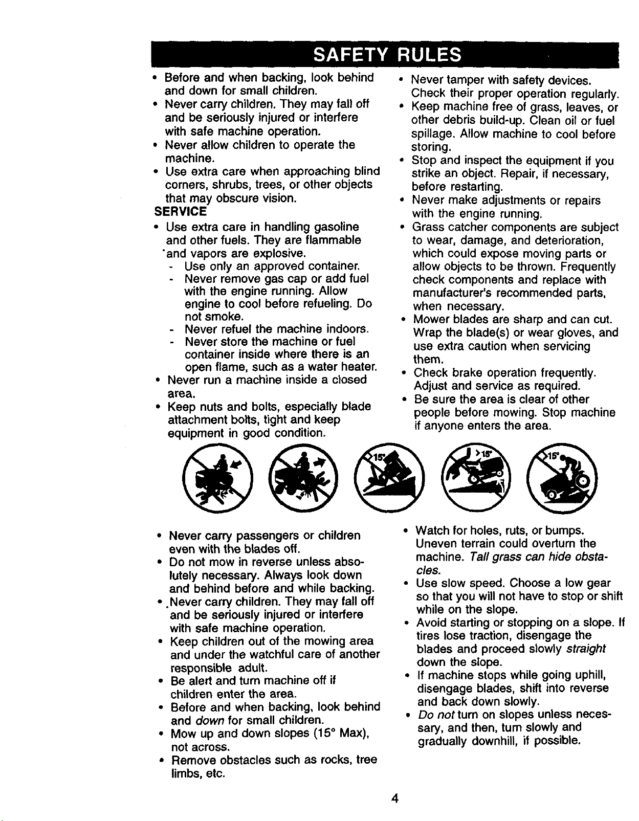
• Never tamper with safety devices.
Check their proper operation regularly.
• Keep machine free of grass, leaves, or
other debris build-up. Clean oil or fuel
spillage. Allow machine to cool before
storing.
• Stop and inspect the equipment if you
strike an object. Repair, if necessary,
before restarting.
° Never make adjustments or repairs
with the engine running.
• Grass catcher components are subject
to wear, damage, and deterioration,
which could expose moving parts or
allow objects to be thrown. Frequently
check components and replace with
manufacturer's recommended parts,
when necessary.
• Mower blades are sharp and can cut.
Wrap the blade(s) or wear gloves, and
use extra caution when servicing
them.
• Check brake operation frequently.
Adjust and service as required.
• Be sure the area is clear of other
people before mowing. Stop machine
if anyone enters the area.
• Never carry passengers or children
even with the blades off.
• Do not mow in reverse unless abso-
lutely necessary. Always look down
and behind before and while backing.
• .Never carry children. They may fall off
and be seriously injured or interfere
with safe machine operation.
• Keep children out of the mowing area
and under the watchful care of another
responsible adult.
• Be alert and turn machine off if
children enter the area.
• Before and when backing, look behind
and down for small children.
• Mow up and down slopes (15 ° Max),
not across.
• Remove obstacles such as rocks, tree
limbs, etc.
• Watch for holes, ruts, or bumps.
Uneven terrain could overturn the
machine. Tall grass can hide obsta-
cles.
• Use slow speed. Choose a low gear
so that you will not have to stop or shift
while on the slope.
• Avoid starting or stopping on a slope. If
tires lose traction, disengage the
blades and proceed slowly straight
down the slope.
• If machine stops while going uphill,
disengage blades, shift into reverse
and back down slowly.
• Do not turn on slopes unless neces-
sary, and then, turn slowly and
gradually downhill, if possible.
4
_Look for this symbol to point out
important safety precautions. It means
CAUTION!!! BECOMEAWARE!flYOUR
_FETY IS INVOLVED.
CAUTION: In order to prevent
accidental starting when setting up,
transporting, adjusting or making repairs
always disconnect spark plug wire and
place wire where it cannot contact spark
CAUTION: Do not coast down a hill in
neutral, you may lose control of the
tractor.
_CAUTION: Tow only the attachments
that are recommended by and comply
with specifications of the manufacturer of
your tractor. Use common sense when
towing. Operate only at the lowest
possible speed when on a slope. Too
heavy of a load, while on a slope, is
dangerous. Tires can lose traction with
the ground and cause you to lose control
_YwOur tractor.
ARNING: The engine exhaust from
this product contains chemicals known to
the State of California to cause cancer,
birth defects, or other reproductive harm.
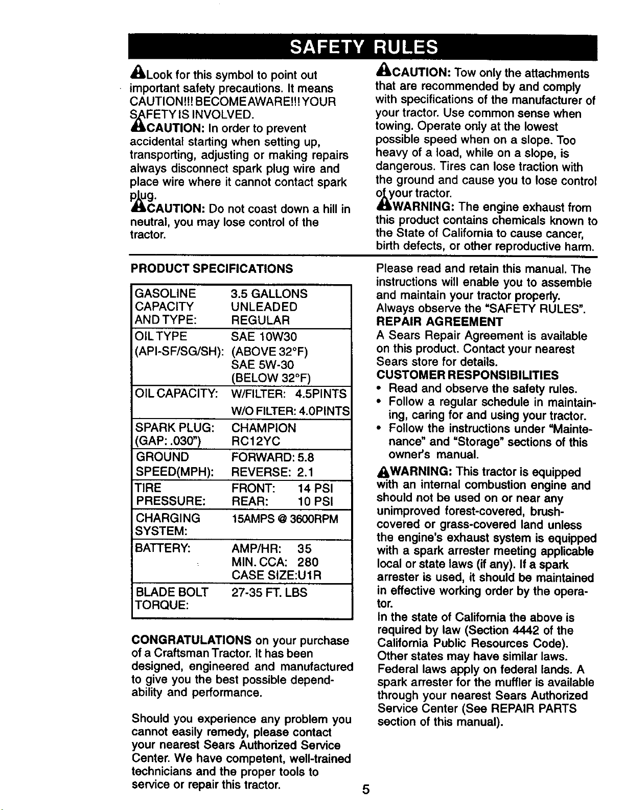
PRODUCT SPECIFICATIONS
GASOLINE
CAPACITY
AND TYPE:
OILTYPE
API-SF/SG/SH):
3.5 GALLONS
UNLEADED
REGULAR
SAE 10W30
(ABOVE 32°F)
SAE 5W-30
(BELOW 32°F)
OILCAPAClTY: W/FILTER: 4.5PINTS
W/O FILTER: 4.0PINTS
SPARK PLUG: CHAMPION
GAP: .030") RCl 2YC
GROUND FORWARD: 5.8
SPEED(MPH): REVERSE: 2.1
TIRE FRONT: 14 PSI
PRESSURE: REAR: 10 PSI
CHARGING 15AMPS @ 3600RPM
SYSTEM:
i
BATTERY: AMP/HR: 35
MIN. CCA: 280
CASE SIZE:U1R
BLADE BOLT 27-35 FT. LBS
TORQUE:
CONGRATULATIONS on your purchase
of a Craftsman Tractor. It has been
designed, engineered and manufactured
to give you the best possible depend-
ability and performance.
Should you experience any problem you
cannot easily remedy, please contact
your nearest Sears Authorized Service
Center. We have competent, well-trained
technicians and the proper tools to
service or repair this tractor.
Please read and retain this manual. The
instructions will enable you to assemble
and maintain your tractor properly.
Always observe the "SAFETY RULES".
REPAIR AGREEMENT
A Sears Repair Agreement is available
on this product. Contact your nearest
Sears store for details.
CUSTOMER RESPONSIBILITIES
* Read and observe the safety rules.
• Follow a regular schedule in maintain-
ing, caring for and using your tractor.
• Follow the instructions under "Mainte-
nance" and "Storage" sections of this
owner's manual.
AWARNING" This tractor is equipped
with an internal combustion engine and
should not be used on or near any
unimproved forest-covered, brush-
covered or grass-covered land unless
the engine's exhaust system is equipped
with a spark arrester meeting applicable
local or state laws (if any). If a spark
arrester is used, it should be maintained
in effective working order by the opera-
tor.
In the state of California the above is
required by law (Section 4442 of the
California Public Resources Code).
Other states may have similar laws.
Federal laws apply on federal lands. A
spark arrester for the muffler is available
through your nearest Sears Authorized
Service Center (See REPAIR PARTS
section of this manual).
5
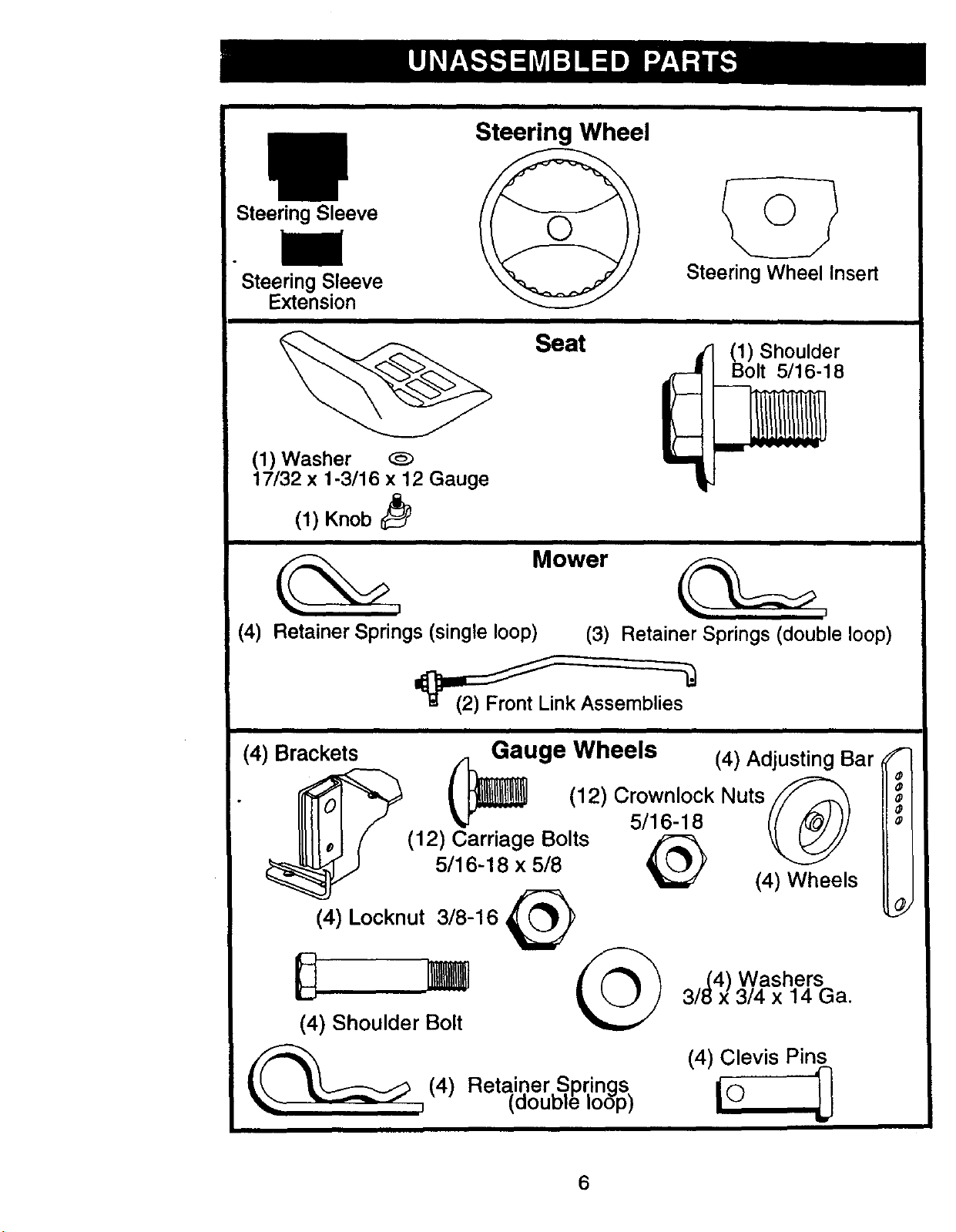
Steering Sleeve
Steering Wheel
Steering Sleeve
Steering Wheel Insert
Extension
i
Seat
(1) Shoulder
Bolt 5/16-18
(1) Washer
17/32 x 1-3/16 x 12 Gauge
(1) Knob
____, Mower
(4) Retainer Springs (single loop) (3) Retainer Springs (double loop)
(4) Brackets Gauge Wheels (4) Adjusting Bar
5/16-18
(12) Carriage Bolts
_ _ _(12) Cr°wnl°ckNuts(_
5/16-18 x 5/8 (4) Wheels
(4) Locknut 3/8-16 _(_
_ _ 4) Washers
3/_ x 3/4 x 14 Ga.
(4) Shoulder Bolt
(4) Reta.iner.S, prings I O
taouDle ioop_
(4) Clevis Pin_
6
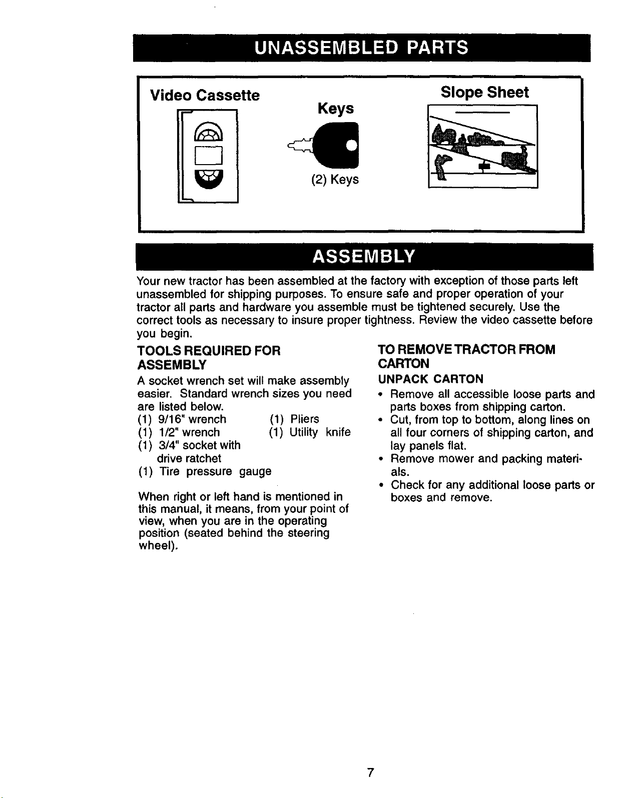
Video Cassette
Slope Sheet
Keys
F-3
Your new tractor has been assembled at the factory with exception of those parts left
unassembled for shipping purposes. To ensure safe and proper operation of your
tractor all parts and hardware you assemble must be tightened securely. Use the
correct tools as necessary to insure proper tightness. Review the video cassette before
you begin.
TOOLS REQUIRED FOR
ASSEMBLY
A socket wrench set will make assembly
easier. Standard wrench sizes you need
are listed below.
(1) 9/16" wrench (1) Pliers
(1) 1/2"wrench (1) Utility knife
(1) 3/4" socket with
drive ratchet
(1) Tire pressure gauge
When right or left hand is mentioned in
this manual, it means, from your point of
view, when you are in the operating
position (seated behind the steering
wheel).
€
(2) Keys
i
TO REMOVE TRACTOR FROM
CARTON
UNPACK CARTON
• Remove all accessible loose parts and
parts boxes from shipping carton.
• Cut, from top to bottom, along lines on
all four corners of shipping carton, and
lay panels flat.
• Remove mower and packing materi-
als.
• Check for any additional loose parts or
boxes and remove.
7

BEFORE REMOVING TRACTOR
FROM SKID
AI-FACH STEERING WHEEL
• Remove hex bolt, lock washer and
large flat washer from steering shaft.
• Position front wheels of the tractor so
they are pointing straight forward.
• Slide the steering sleeve over the
steering shaft.
• "Align tabs and press steering sleeve
extension into bottom of steering
wheel.
• Position steering wheel so cross bars
are horizontal (left to right) and slide
onto steering wheel adapter.
• Secure steering wheel to steering
shaft with hex bolt, lock washer and
large flat washer previously removed.
Tighten securely.
• Snap steering wheel insert into center
of steering wheel.
• Remove protective materials from
tractor hood and grill.
IMPORTANT: Check for and remove any
staples in skid that may puncture tires
where tractor is to roll off skid.
_--_ Wheel Insert
---- Hex Bolt
_,-----Lock Washer
^- • Large Flat
_teerlng _ • .
Wheel__ wasner
_/Steedng Wheel
• _/_ Adapter
Steering
Sleeve _-..._::::=:--Tabs
Extension
Steedng Shaft
Steering
Sleeve
(label located between terminals)
charge battery for minimum of one
hour at 6-10 amps. (See "BATTERY" in
Maintenance section of this manual
for charging instructions).
'"_'_ """ Label
INSTALL SEAT
Adjust seat before tightening adjustment
knob.
• Remove adjustment knob and flat
washer securing seat to cardboard
packing and set aside for assembly of
seat to tractor.
• Pivot seat upward and remove from
the cardboard packing. Remove the
cardboard packing and discard.
• Place seat on seat pan and assemble
shoulder bolt. Tighten shoulder bolt
securely.
• Assemble adjustment knob and flat
washer loosely. Do not tighten.
• Lower seat into operating position and
sit on seat.
• Slide seat until a comfortable position
is reached which allows you to press
clutch/brake pedal all the way down.
• Get off seat without moving its adjusted
position.
• Raise seat and tighten adjustment
knob securely.
Seat Pan
Shoulder
Bolt
HOW TO SET UP YOUR TRACTOR
CHECK BATTERY
• Lift hood to raised position.
• If this battery is put into service after
month and year indicated on label
Adjustment
Knob
NOTE: You may now roll or drive your
tractor off the skid. Follow the appropriate
instruction below to remove the tractor
from the skid.
8
TO ROLL TRACTOR OFF SKID (See
Operation section for location and
function of controls)
• Press lift lever plunger and raise
attachment lift lever to its highest
position.
• Release parking brake by depressing
clutch/brake pedal.
• Place freewheel control in freewheel-
ing position to disengage transmis-
sion (See TO TRANSPORT" in the
Operation section of this manual).
• Roll tractor forward off skid.
TO DRIVE TRACTOR OFF SKID
(See Operation section for location
and function of controls)
_WARNING: Before starting, read,
understand and follow all instructions in
the Operation section of this manual. Be
sure tractor is in a well-ventilated area.
Be sure the area in front of tractor is
clear of other people and objects.
• Be sure all the above assembly steps
have been completed.
• Check engine oil level and fill fuel
tank with gasoline.
• Place freewheel control in =transmis-
sion engaged" position.
• Sit on seat in operating position,
depress clutch/brake pedal and set
the parking brake.
• Place motion control lever in neutral
(N) position.
• Press lift lever plunger and raise
attachment lift lever to its highest
position.
• Start the engine. After engine has
started, move throttle control to idle
position.
• Release parking brake.
• Slowly move the motion control lever
forward and slowly drive tractor off
skid.
• Apply brake to stop tractor, set parking
brake and place gearshift lever in
neutral position.
• Turn ignition key to =OFF" position.
Continue with the instructions that follow.
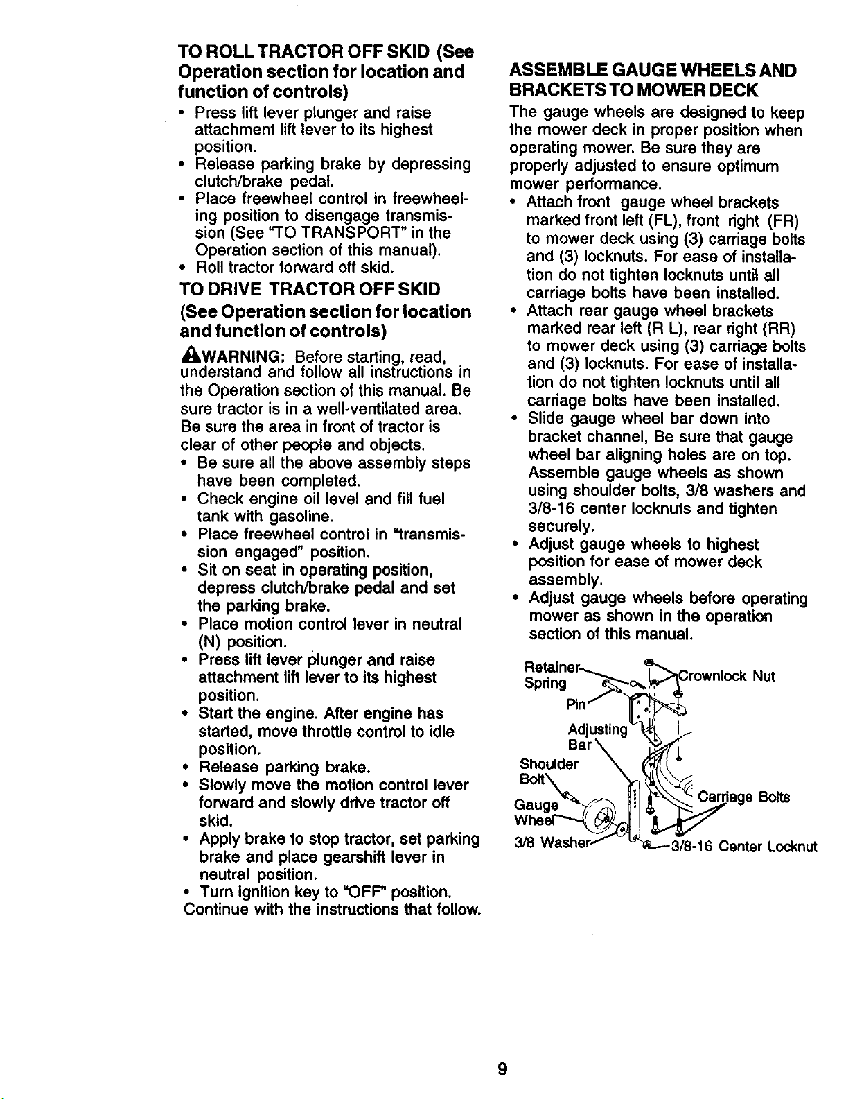
ASSEMBLE GAUGE WHEELS AND
BRACKETS TO MOWER DECK
The gauge wheels are designed to keep
the mower deck in proper position when
operating mower. Be sure they are
properly adjusted to ensure optimum
mower performance.
• Attach front gauge wheel brackets
marked front left (FL), front right (FR)
to mower deck using (3) carriage bolts
and (3) Iocknuts. For ease of installa-
tion do not tighten Iocknuts until all
carriage bolts have been installed.
• Attach rear gauge wheel brackets
marked rear left (R L), rear right (RR)
to mower deck using (3) carriage bolts
and (3) Iocknuts. For ease of installa-
tion do not tighten Iocknuts until all
carriage bolts have been installed.
• Slide gauge wheel bar down into
bracket channel, Be sure that gauge
wheel bar aligning holes are on top.
Assemble gauge wheels as shown
using shoulder bolts, 3/8 washers and
3/8-16 center Iocknuts and tighten
securely.
• Adjust gauge wheels to highest
position for ease of mower deck
assembly.
• Adjust gauge wheels before operating
mower as shown in the operation
section of this manual.
Spdng
Adjusting
Bar
Shoulder \
GauB°ltge_
3/8
Nut
Bolts
Center Locknut
9
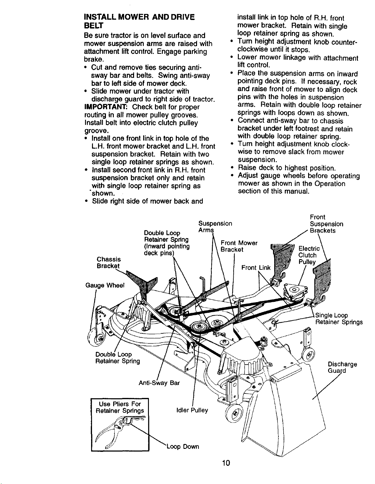
INSTALL MOWER AND DRIVE
BELT
Be sure tractor is on level surface and
mower suspension arms are raised with
attachment lift control. Engage parking
brake,
• Cut and remove ties securing anti-
sway bar and belts. Swing anti-sway
bar to left side of mower deck.
• Slide mower under tractor with
discharge guard to right side of tractor.
IMPORTANT: Check belt for proper
routing in all mower pulley grooves.
Install belt into electric clutch pulley
groove.
• Install one front link in top hole of the
L.H. front mower bracket and L.H, front
suspension bracket. Retain with two
single loop retainer springs as shown.
• Install second front link in R.H, front
suspension bracket only and retain
with single loop retainer spring as
•shown.
• Slide right side of mower back and
install link in top hole of R.H. front
mower bracket. Retain with single
loop retainer spring as shown.
Turn height adjustment knob counter-
clockwise until it stops.
Lower mower linkage with attachment
lift control.
Place the suspension arms on inward
pointing deck pins. It necessary, rock
and raise front of mower to align deck
pins with the holes in suspension
arms. Retain with double loop retainer
springs with loops down as shown.
Connect anti-sway bar to chassis
bracket under left footrest and retain
with double loop retainer spring.
Turn height adjustment knob clock-
wise to remove slack from mower
suspension.
Raise deck to highest position.
Adjust gauge wheels before operating
mower as shown in the Operation
section of this manual.
Chassis
Bracket
Gauge Wheel
Retainer Spring
Loop
Double Loop
Retainer Spring
(Inward pointing
deck pins:
Bar
Suspension
Arms
Front Mower
Bracket
Front
Suspension
Front Link
Single Loop
Retainer Springs
Discharge
Idler Pulley
Down
I0

CHECK TIRE PRESSURE
The tires on your tractor were overin-
flated at the factory for shipping pur-
poses. Correct tire pressure is important
for best cutting performance.
• Reduce tire pressure to PSI shown in
=PRODUCT SPECIFICATIONS"
section of this manual.
CHECK MOWER LEVELNESS
For best cutting results, mower should be
properly leveled. See "TO LEVEL
MOWER HOUSING" in the Service and
Adjustments section of this manual.
CHECK FOR PROPER POSITION
OF ALL BELTS
See the figures that are shown for
replacing motion, mower drive, and
mower blade drive belts in the Service
and Adjustments section of this manual.
Verify that the belts are routed correctly.
CHECK BRAKE SYSTEM
After you learn how to operate your
tractor, check to see that the brake is
properly adjusted. See 'q-O ADJUST
BRAKE" in the Service and Adjustments
section of this manual.
CHECKLIST
BEFORE YOU OPERATE AND ENJOY
YOUR NEW TRACTOR, WE WISH TO
ASSURE THAT YOU RECEIVE THE
BEST PERFORMANCE AND
SATISFACTION FROM THIS QUALITY
PRODUCT.
PLEASE REVIEW THE FOLLOWING
CHECKLIST:
,/ All assembly instructions have been
completed.
,/No remaining loose parts in carton.
1/'Battery is properly prepared and
charged. (Minimum 1 hour at 6
amps).
,/Seat is adjusted comfortably and
tightened securely.
,/All tires are properly inflated. (For
shipping purposes, the tires were
overinflated at the factory).
,/Be sure mower deck is properly
leveled side-to-side/front-to-rear for
best cutting results. (Tires must be
properly inflated for leveling).
,/Check mower and drive belts. Be sure
they are routed properly around
pulleys and inside all belt keepers.
,/Check wiring. See that all connections
are still secure and wires are properly
clamped.
•/ Before driving tractor, be sure free-
wheel control is in drive position.
WHILE LEARNING HOWTO USE YOUR
TRACTOR, PAY EXTRAATTENTION TO
THE FOLLOWING IMPORTANT ITEMS:
,/" Engine oil is at proper level.
,/Fuel tank is filled with fresh, clean,
regular unleaded gasoline.
,I Become familiar with all controls - their
location and function. Operate them
before you start the engine.
,/Be sure brake system is in safe
operating condition.
,/" It is important to purge the transmis-
sion before operating your tractor for
the first time. Follow proper starting
and transmission purging instructions
(See "TO START ENGINE" and
"PURGE TRANSMISSION" in the
Operation section of this manual).
11
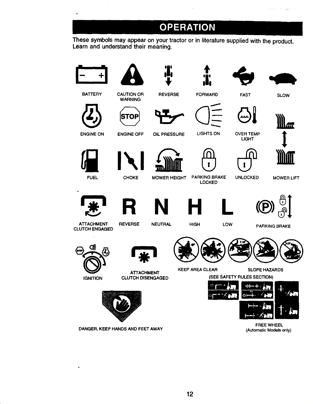
These symbols may appear on your tractor or in literature supplied with the product.
Leam and understand their meaning.
BATTERY CAUTION OR
WARNING
ENGINE ON ENGINE OFF OIL PRESSURE LIGHTS ON
FUEL CHOKE MOWER HEIGHT PARKING BRAKE UNLOCKED MOWER LIFT
REVERSE FORWARD FAST SLOW
LOCKED
R N H L
ATTACHMENT REVERSE NEUTRAL HIGH LOW PARKING BRAKE
CLUTCH ENGAGED
___) ATTACHMENT KEEP AREA CLEAR SLOPE HAZARDS
IGNITION CLUTCH DISENGAGED
DANGER, KEEP HANDS AND FEET AWAY
(SEE SAFETY RULES SECTION)
FREE WHEEL
(Automatic Models only)
12
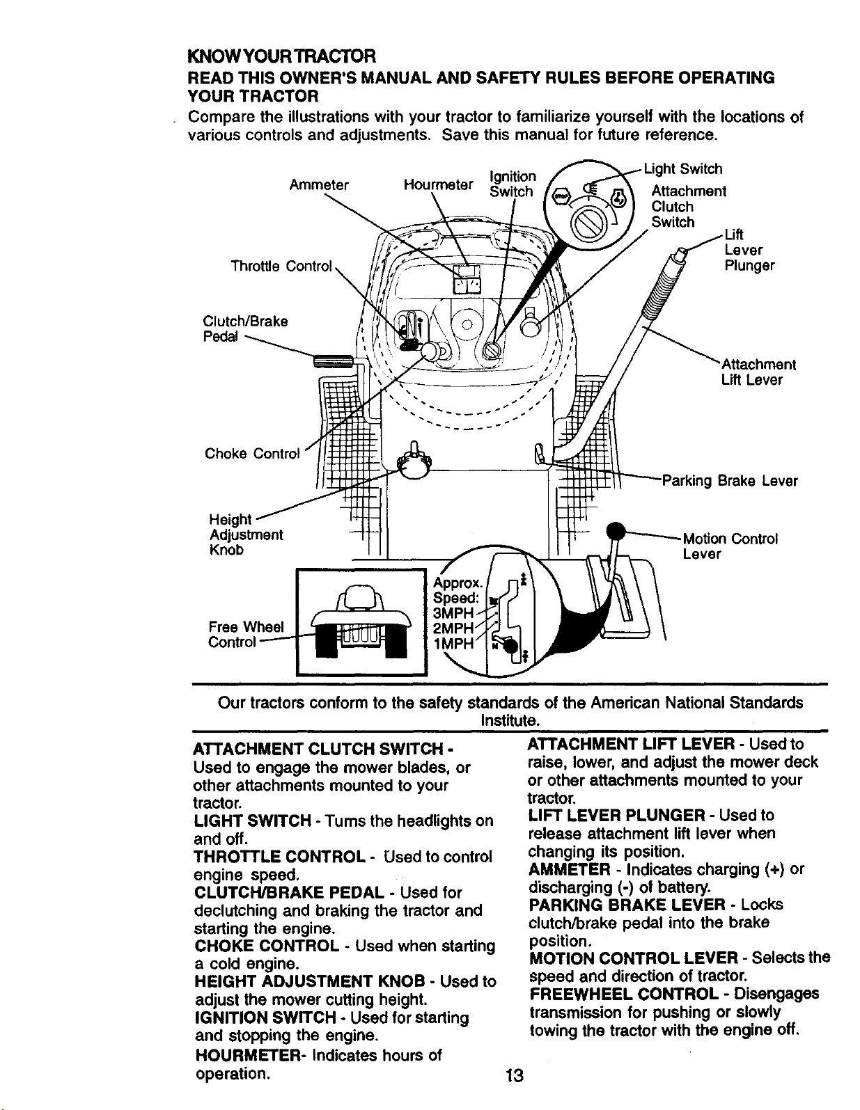
KNOW YOUR TRACTOR
READ THIS OWNER'S MANUAL AND SAFETY RULES BEFORE OPERATING
YOUR TRACTOR
Compare the illustrations with your tractor to familiarize yourself with the locations of
various controls and adjustments. Save this manual for future reference.
Ammeter Hourmeter Switch
Throttle Control
Clutch/Brake
Choke Control
Height
Adjustment Motion Control
Knob Lever
Ignition
Attachment
Clutch
Switch
Lever
Plunger
'Attachment
Lift Lever
Brake Lever
Approx.
Speed:
Our tractors conform to the safety standards of the American National Standards
Institute.
ATTACHMENT CLUTCH SWITCH -
Used to engage the mower blades, or
other attachments mounted to your
tractor.
LIGHT SWITCH - Turns the headlights on
and off.
THROTTLE CONTROL - Used to control
engine speed.
CLUTCH/BRAKE PEDAL - Used for
declutching and braking the tractor and
starting the engine.
CHOKE CONTROL - Used when starting
a cold engine.
HEIGHT ADJUSTMENT KNOB - Used to
adjust the mower cutting height.
IGNITION SWITCH - Used for starting
and stopping the engine.
ATTACHMENT LIFT LEVER - Used to
raise, lower, and adjust the mower deck
or other attachments mounted to your
tractor.
LIFT LEVER PLUNGER - Used to
release attachment lift lever when
changing its position.
AMMETER - Indicates charging (+) or
discharging (-) of battery.
PARKING BRAKE LEVER - Locks
clutch/brake pedal into the brake
position.
MOTION CONTROL LEVER - Selects the
speed and direction of tractor.
FREEWHEEL CONTROL - Disengages
transmission for pushing or slowly
towing the tractor with the engine off.
HOURMETER- Indicates hours of
operation.
13
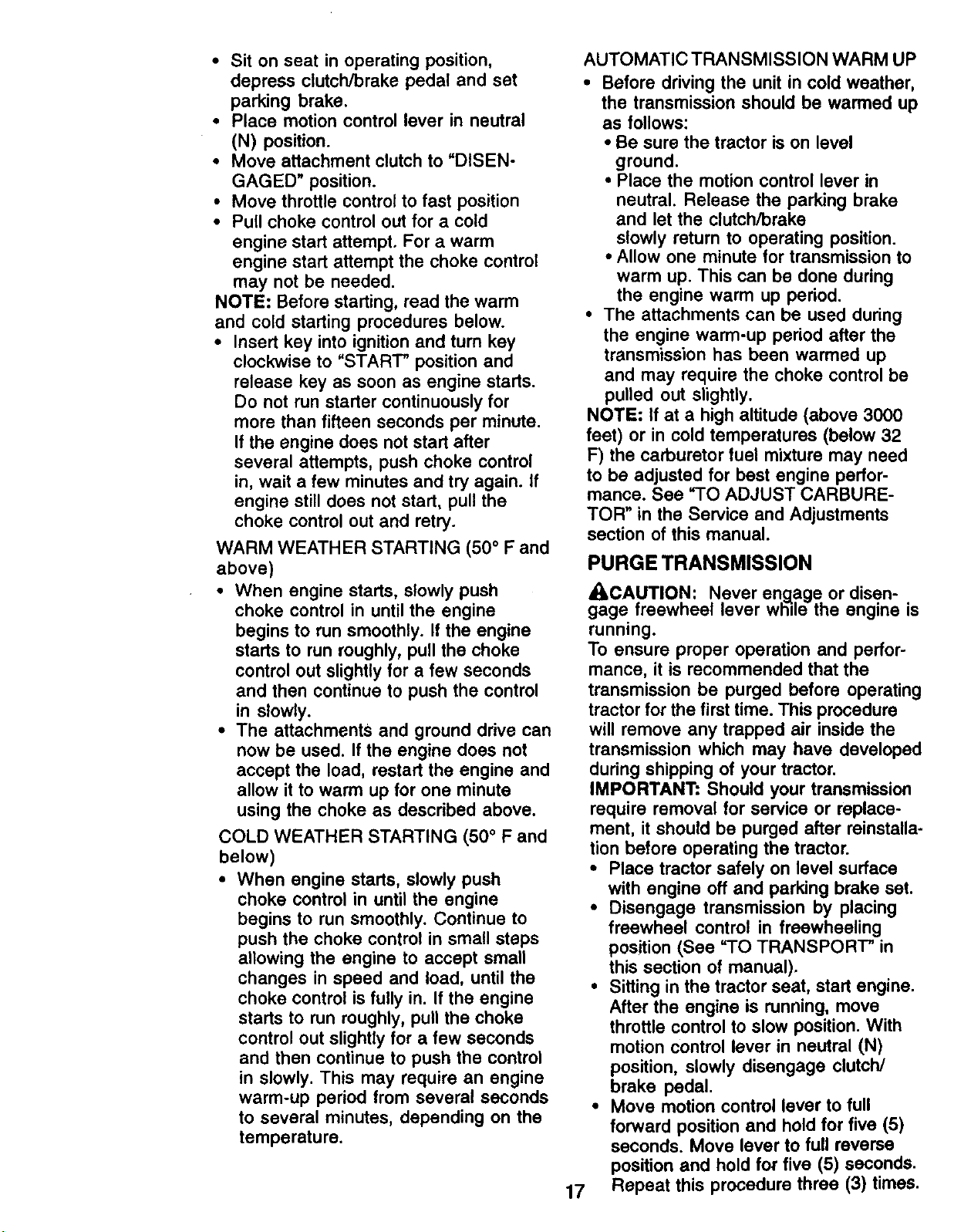
The operation of any tractor can result in foreign objects thrown into
the eyes, which can result in severe eye damage. Always wear safety
glasses or eye shields while operating your tractor or performing any
adjustments or repairs. We recommend a wide vision safety mask
over spectacles or standard safety glasses.
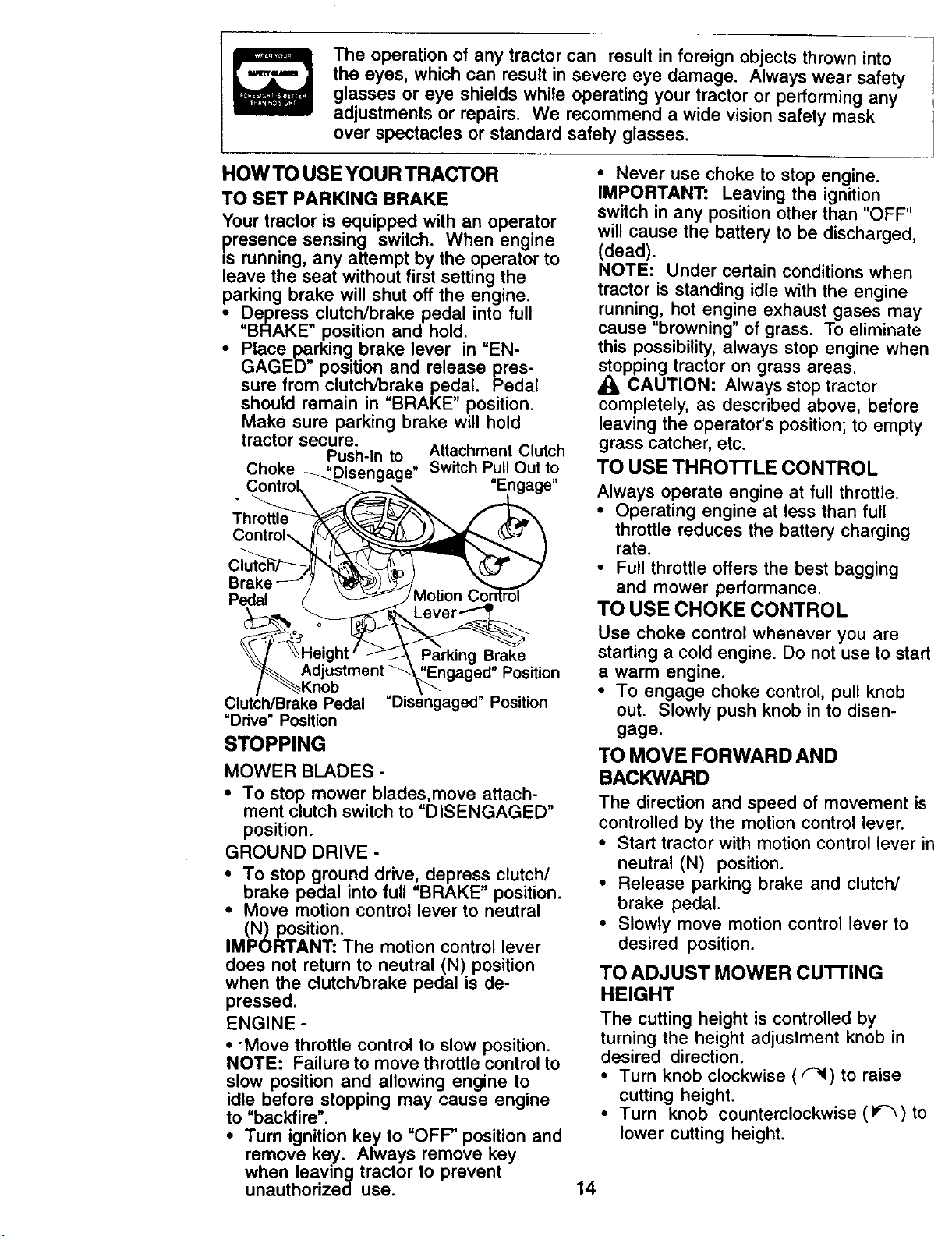
HOW TO USEYOUR TRACTOR
TO SET PARKING BRAKE
Your tractor is equipped with an operator
presence sensing switch. When engine
is running, any attempt by the operator to
leave the seat without first setting the
parking brake will shut off the engine.
Depressclutch/brake pedal into full
i BRAKE position and hold.
Place parking brake lever in "EN-
GAGED" position and release pres-
sure from clutch/brake pedal. Pedal
should remain in "BRAKE" position.
Make sure parking brake will hold
tractor secure.
Push-In to Attachment Clutch
Choke "Disengage" SwitchPull Out to
Control, _,_" "Engage"
Brake _J / )!_I_)_5_/ ....... "....,_.</.
Pedal / _ j Mouon t_omrol
_ever_
__t _Engaged" Position
/ _'_Knob \_---
Clutch/BrakePedal "Disengaged" Position
"Ddve"Position
STOPPING
MOWER BLADES -
• To stop mower blades,move attach-
ment clutch switch to "DISENGAGED"
position.
GROUND DRIVE -
• To stop ground ddve, depress clutch/
brake pedal into full "BRAKE" position.
• Move motion control lever to neutral
(N) position.
IMPORTANT: The motion control lever
does not return to neutral (N) position
when the clutch/brake pedal is de-
pressed.
ENGINE -
• -Move throttle control to slow position.
NOTE: Failure to move throttle control to
slow position and allowing engine to
idle before stopping may cause engine
to "backfire".
• Turn ignition key to "OFF" position and
remove key. Always remove key
when leaving tractor to prevent
unauthorized use.
• Never use choke to stop engine.
IMPORTANT: Leaving the ignition
switch in any position other than "OFF"
will cause the battery to be discharged,
(dead).
NOTE: Under certain conditions when
tractor is standing idle with the engine
running, hot engine exhaust gases may
cause "browning" of grass. To eliminate
this possibility, always stop engine when
_lopping tractor on grass areas.
CAUTION: Always stop tractor
completely, as described above, before
leaving the operator's position; to empty
grass catcher, etc.
TO USE THRO'n'LE CONTROL
Always operate engine at ful! throttle.
• Operating engine at less than full
throttle reduces the battery charging
rate.
• Full throttle offers the best bagging
and mower performance.
TO USE CHOKE CONTROL
Use choke control whenever you are
starting a cold engine. Do not use to start
a warm engine.
• To engage choke control, pull knob
out. Slowly push knob in to disen-
gage.
TO MOVE FORWARD AND
BACKWARD
The direction and speed of movement is
controlled by the motion control lever.
• Start tractor with motion control lever in
neutral (N) position.
• Release parking brake and clutch/
brake pedal.
• Slowly move motion control lever to
desired position.
TO ADJUST MOWER CU'I-FING
HEIGHT
The cutting height is controlled by
turning the height adjustment knob in
desired direction.
• Turn knob clockwise ((_) to raise
cutting height.
• Turn knob counterclockwise (1_)to
lower cutting height.
14

The cutting height range is approxi-
mately 1-1/2" to 4". The heights are
measured from the ground to the blade
tip with the engine not running. These
heights are approximate and may vary
depending upon soil conditions, height
of grass and types of grass being
mowed.
• The average lawn should be cut to
approximately 2-1/2 inches during the
cool season and to over 3 inches
during hot months. For healthier and
better looking lawns, mow often and
after moderate growth.
• For best cutting performance, grass
over 6 inches in height should be
mowed twice. Make the first cut
relatively high; the second to desired
height.
TO ADJUST GAUGE WHEELS
Gauge wheels are properly adjusted
when they are slightly off the ground
when mower is at the desired cutting
height in operating position. Gauge
wheels then keep the deck in proper
position to help prevent scalping in most
terrain conditions.
• Be sure tractor is on a flat level
surface.
• Lower mower and adjust mower to
desired cutting height.
• Remove retainer spring and clevis pin
which secure each gauge wheel bar.
• Lower gauge wheels to ground. Raise
gauge wheels slightly to align holes in
bracket and gauge wheel bar and
insert clevis pin. Gauge wheels should
be slightly off the ground.
• Replace retainer spring into clevis pin.
IMPORTANT: Be sure to readjust gauge
wheels if you change the cutting height
of the cutting unit.
Retainer
Spring
levis
-- Pin
TO OPERATE MOWER
Your tractor is equipped with an operator
presence sensing switch. Any attempt by
the operator to leave the seat with the
engine running and the attachment
clutch engaged will shut off the engine.
• Select desired height of cut.
• Lower mower with attachment lift
control.
• Start mower blades by engaging
attachment clutch control.
• TO STOP MOWER BLADES - disen-
gage attachment clutch control.
,A CAUTION: Do not operate the mower
without either the entire grass catcher, on
mowers so equipped, or the deflector
shield in place.
Attachment Clutch Attachernnt Lift
Switch Pull Out to Lever High
"Engage" Position
,Low
":' Position
_to
"Disengage"
Deflector
Shield
TO OPERATE ON HILLS
• ILCAUTION; Do not drive up or down
hills with slopes greater than 15° and do
not drive across any slope.
• Choose the slowest speed before
starting up or down hills.
• Avoid stopping or changing speed on
hills.
• If slowing is necessary, move throttle
control lever to slower position.
• If stopping is absolutely necessary,
push clutch/brake pedal quickly to
brake position and engage parking
brake.
• Move motion control lever to slowest
setting.
IMPORTRANT: The motion control lever
does not return to neutral (N) position
when the clutch/brake pedal is de-"
pressed.
• To restart movement, slowly release
parking brake and clutch/brake pedal.
• Slowly move motin control lever to
slowest setting.
• Make all turns slowly.
15

TO TRANSPORT
When pushing or towing your tractor, be
sure to disengage transmission by
placing freewheel control in freewheel-
ing position. Free wheel control is
located at the rear drawbar of tractor.
• Raise attachment lift to highest
position with attachment lift control.
• Remove retainer spring from free-
wheel control rod.
• Push control rod in to disengage
transmission and reinsert retainer
spring into control rod hole now on
back side of the bracket.
• Do not push or tow tractor at more
than two (2) MPH.
• To reengage transmission, reverse
above procedure.
NOTE: To protect hood from damage
when transporting your tractor on a truck
or a trailer, be sure hood is closed and
secured to tractor. Use an appropriate
means of tying hood to tractor (rope,
cord, etc.).
TOWING CARTS AND OTHER
ATTACHMENTS
Tow only the attachments that are
recommended by and comply with
specifications of the manufacturer of your
tractor. Use common sense when towing.
Too heavy of a load, while on a slope, is
dangerous. "13rescan lose traction with
the ground and cause you to lose control
of your tractor.
BEFORE STARTING THE ENGINE
CHECK ENGINE OIL LEVEL
• The engine in your tractor has been
shipped, from the factory, already filled
with summer weight oil.
• Check engine oil with tractor on level
ground.
• Unthread and remove oil fill cap/
dipstick; wipe oil off. Reinsert the
dipstick into the tube and rest oil fill
cap on the tube. Do not thread the cap
onto the tube. Remove and read oil
level. If necessary, add oil until
"FULL" mark on dipstick is reached.
Do not overfill.
• For cold weather operation you should
change oil for easier starting (See "OIL
VISCOSITY CHART" in the Mainte-
nance section of this manual).
• To change engine oil, see the Mainte-
nance section in this manual.
ADD GASOLINE
* Fill fuel tank. Use fresh, clean, regular
unleaded gasoline with a minimum of
87 octane. (Use of leaded gasoline
will increase carbon and lead oxide
deposits and reduce valve life). Do
not mix oil with gasoline. Purchase
fuel in quantities that can be used
within 30 days to assure fuel fresh-
ness.
IMPORTANT: When operating in
temperatures below 32°F(0°C), use
fresh, clean winter grade gasoline to
help insure good cold weather starting.
A, WARNING: Experience indicates that
alcohol blended fuels (called gasohol or
using ethanol or methanol) can attract
moisture which leads to separation and
formation of acids during storage. Acidic
gas can damage the fuel system of an
engine while in storage. To avoid engine
problems, the fuel system should be
emptied before storage of 30 days or
longer. Drain the gas tank, start the
engine and let it run until the fuel lines
and carburetor are empty. Use fresh fuel
next season. See Storage Instructions
for additional information. Never use
engine or carburetor cleaner products in
the fuel tank or permanent damage may
occur.
_eCAUTION • Fill to bottom of gas tank
r neck. Do not overfill. Wipe off any
spilled oil or fuel. Do not store, spill or
use gasoline near an open flame.
TO START ENGINE
When starting the engine for the first time
or if the engine has run out of fuel, itwill
take extra cranking time to move fuel
from the tank to the engine.
• Be sure freewheel control is in the
transmission engaged position.
16
• Sit on seat in operating position,
depress clutch/brake pedal and set
parking brake.
• Place motion control lever in neutral
(N) position.
• Move attachment clutch to "DISEN-
GAGED" position.
• Move throttle control to fast position
• Pull choke control out for a cold
engine start attempt. For a warm
engine start attempt the choke control
may not be needed.
NOTE: Before starting, read the warm
and cold starting procedures below.
• Insert key into ignition and turn key
clockwise to "START" position and
release key as soon as engine starts.
Do not run starter continuously for
more than fifteen seconds per minute.
If the engine does not start after
several attempts, push choke control
in, wait a few minutes and try again. If
engine still does not start, pull the
choke control out and retry.
WARM WEATHER STARTING (50° F and
above)
• When engine starts, slowly push
choke control in until the engine
begins to run smoothly. If the engine
starts to run roughly, pull the choke
control out slightly for a few seconds
and then continue to push the control
in slowly.
• The attachments and ground drive can
now be used. If the engine does not
accept the load, restart the engine and
allow it to warm up for one minute
using the choke as described above.
COLD WEATHER STARTING (50 ° F and
below)
• When engine starts, slowly push
choke control in until the engine
begins to run smoothly. Continue to
push the choke control in small steps
allowing the engine to accept small
changes in speed and load, until the
choke control is fully in. If the engine
starts to run roughly, pull the choke
control out slightly for a few seconds
and then continue to push the control
in slowly. This may require an engine
warm-up period from several seconds
to several minutes, depending on the
temperature.
AUTOMATIC TRANSMISSION WARM UP
• Before driving the unit in cold weather,
the transmission should be warmed up
as follows:
• Be sure the tractor is on level
ground.
• Place the motion control lever in
neutral. Release the parking brake
and let the clutch/brake
slowly return to operating position.
• Allow one minute for transmission to
warm up. This can be done during
the engine warm up period.
• The attachments can be used during
the engine warm-up period after the
transmission has been warmed up
and may require the choke control be
pulled out slightly.
NOTE: If at a high altitude (above 3000
feet) or in cold temperatures (below 32
F) the carburetor fuel mixture may need
to be adjusted for best engine perfor-
mance. See "TO ADJUST CARBURE-
TOR" in the Service and Adjustments
section of this manual.
PURGE TRANSMISSION
_.,CAUTION: Never engage or disen-
gage freewheel lever wli=le the engine is
running.
To ensure proper operation and perfor-
mance, it is recommended that the
transmission be purged before operating
tractor for the first time. This procedure
will remove any trapped air inside the
transmission which may have developed
during shipping of your tractor.
IMPORTANT: Should your transmission
require removal for service or replace-
ment, it should be purged after reinstalla-
tion before operating the tractor.
• Place tractor safely on level surface
with engine off and parking brake set.
• Disengage transmission by placing
freewheel control in freewheeling
position (See "TO TRANSPORT" in
this section of manual).
• Sitting in the tractor seat, start engine.
After the engine is running, move
throttle control to slow position. With
motion control lever in neutral (N)
position, slowly disengage clutch/
brake pedal.
• Move motion control lever to full
forward position and hold for five (5)
seconds. Move lever to full reverse
position and hold for five (5) seconds.
Repeat this procedure three (3) times.
17
NOTE: During this procedure there will
be no movementof drive wheels. The air
is being removed from hydraulic drive
system.
• Move motion control lever to neutral
(N) position. Shut- off engine and set
parking brake.
• Engage transmission by placing
freewheel control in driving position
"(See "TO TRANSPORT" in this section
of manual).
• Sitting in the tractor seat, start engine.
After the engine is running, move
throttle control to half (1/2) speed. With
motion control lever in neutral (N)
position, slowly disengage clutch/
brake pedal.
• Slowly move motion control lever
forward, after the tractor moves
approximately five (5) feet, slowly
move motion control lever to reverse
position. After the tractor moves
approximately five (5) feet return the
motion control lever to the neutral (N)
position. Repeat this procedure with
the motion control lever three (3)
times.
• Your tractor is now purged and now
ready for normal operation.
MOWING TIPS
• Tire chains cannot be used when the
mower housing is attached to tractor.
• Mower should be properly leveled for
best mowing performance. See "TO
LEVEL MOWER HOUSING" in the
Service and Adjustments section of
this manual.
• The left hand side of mower should be
used for trimming.
• Drive so that clippings are discharged
onto the area that has been cut. Have
the cut area to the right of the tractor.
This will result in a more even distribu-
tion of clippings and more uniform
cutting.
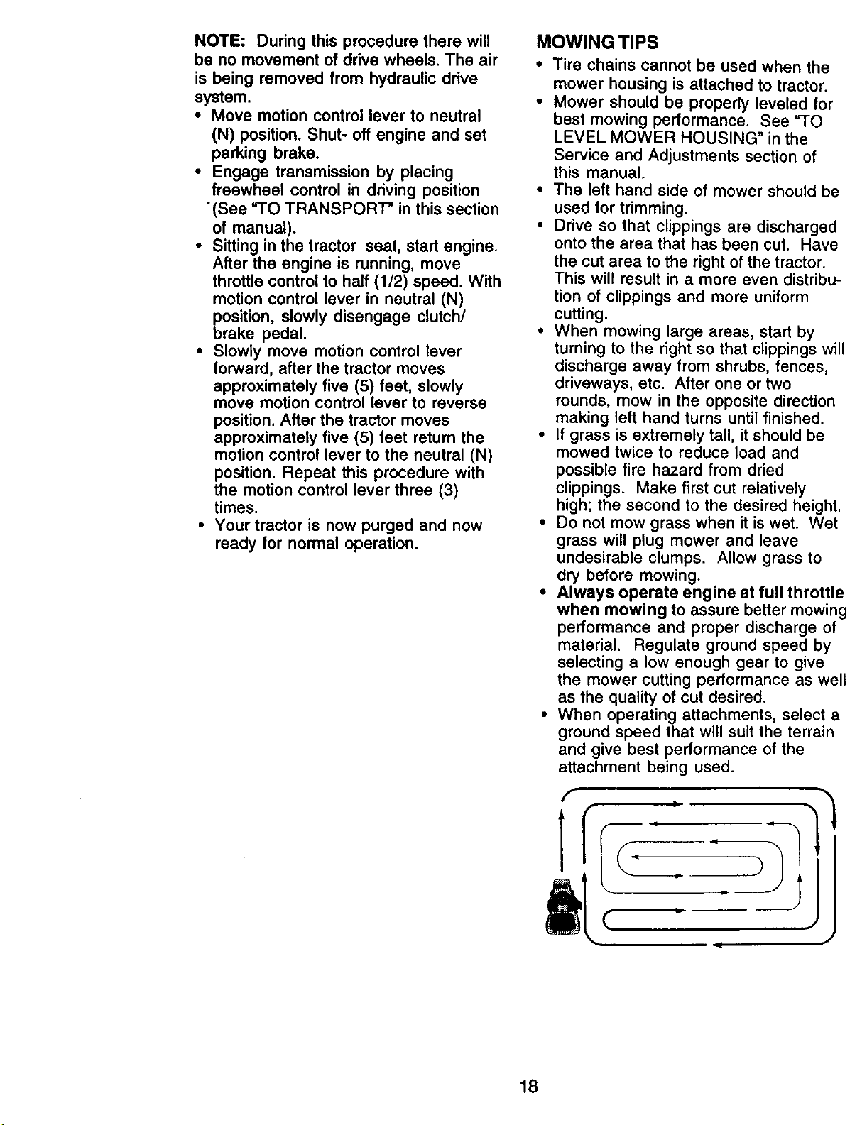
• When mowing large areas, start by
turning to the right so that clippings will
discharge away from shrubs, fences,
driveways, etc. After one or two
rounds, mow in the opposite direction
making left hand turns until finished.
• If grass is extremely tall, it should be
mowed twice to reduce load and
possible fire hazard from dried
clippings. Make first cut relatively
high; the second to the desired height.
• Do not mow grass when it is wet. Wet
grass will plug mower and leave
undesirable clumps. Allow grass to
dry before mowing.
• Always operate engine at full throttle
when mowing to assure better mowing
performance and proper discharge of
material. Regulate ground speed by
selecting a low enough gear to give
the mower cutting performance as well
as the quality of cut desired.
• When operating attachments, select a
ground speed that will suit the terrain
and give best performance of the
attachment being used.
18
¢ "-
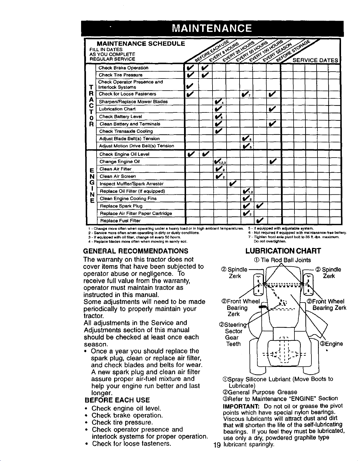
MAINTENANCE SCHEDULE
FILL IN DATES
AS YOU COMPLETE
REGULAR SERVICE IERVICE DATES
Check Brake Operati_'_ _
Check Tire Pressure
Check Operator Presence and
T Interlock Systems t_
R Check for Loose Fasteners _ _7 If
T Lubdcation Chart V'
A Sharpen/Replace Mower Blades _4
0 Check Battery Level
R Clean Battery and Terminals
Check Transaxle Cooling I_
Adjust Blade Belt(s) Tension _s
Adjust Motion Drive Belt(s) Tension
Check Engine Oil Level _ li_
Change Engine
E CleanAirFilter _;
N Clean Air Screen
G Inspect Muffler/Spark Arrester tl_
Replace equipped)
NO Oil Filter (if 1_1,2
E Clean Engine Cooling Fins
Replace Spark Plug I_ V'
Oil I 1_1.2._ V'
v'.
v',Replace Air Filter Paper Cartridge
Replace Fuel Filter t=##
I -Change more often when operating under a heavy load or in high ambienl temperatures. 5 - If e_luippedwith adjustable system.
2 - Service more often when operet_ng in dirty or duSty conditions¸ 6 - Not tequireq if equipped with rnaintenance*ftee battery
3 * If equipped with oil filter, change oil every 50 hours, 7 - Tighten front axle piVOtholt to 35 ft,-Ibs, maximum,
4 ° Replace blades more often when mowing in sandy soil, Do not overfightan.
GENERAL RECOMMENDATIONS
The warranty on this tractor does not
cover items that have been subjected to
operator abuse or negligence. To
receive full value from the warranty,
operator must maintain tractor as
instructed in this manual.
Some adjustments will need to be made
periodically to properly maintain your
tractor.
All adjustments in the Service and
Adjustments section of this manual
should be checked at least once each
season.
• Once a year you should replace the
spark plug, clean or replace air filter,
and check blades and belts for wear.
A new spark plug and clean air filter
assure proper air-fuel mixture and
help your engine run better and last
longer.
BEFORE EACH USE
• Check engine oil level.
• Check brake operation.
• Check tire pressure.
• Check operator presence and
interlock systems for proper operation.
• Check for loose fasteners.
(_Front Wheel
Bearing =_
Zerk
_Steering-1 |
Sector )
Gear
Teeth _
(_Spray ;iliconeLubriant(Move Boots to
(_General Purpose Grease
(_Refer to Maintenance "ENGINE" Section
IMPORTANT: Do not oil or grease the pivot
points whichhave special nylon bearings.
Viscouslubricantswill attractdust and dirt
that willshortenthe lifeof the self-lubricating
bearings. If you feel they must be lubricated,
use only a dry,powdered graphitetype
19 lubricantsparingly.
LUBRICATION CHART
Spindle
Zer_
Lubricate
(_ Tie Rod Ball Joints
_r--- _)FrolP indle
J "I, _ @Engine
_ I I ----,
\ '-::" j
Zerk
t Wheel
Bearing ZeN

TRACTOR
Always observe safety rules when
performing any maintenance.
BRAKE OPERATION
If tractor requires more than six (6) feet
stopping distance at high speed in
highest gear, then brake must be
adjusted. (See "TO ADJUST BRAKE" in
the Service and Adjustments section of
this manual).
TIRES
• Maintain proper air pressure in all tires
(See "PRODUCT SPECIFICATIONS"
section of this manual).
• Keep tires free of gasoline, oil, or
insect control chemicals which can
harm rubber.
• Avoid stumps, stones, deep ruts, sharp
objects and other hazards that may
cause tire damage.
NOTE: To seal tire punctures and
prevent flat tires due to slow leaks, tire
sealant may be purchased from your
local parts dealer. Tire sealant also
prevents tire dry rot and corrosion.
OPERATOR PRESENCE SYSTEM
Be sure operator presence and interlock
systems are working properly. If your
tractor does not function as described,
repair the problem immediately.
• The engine should not start unless the
clutch/brake pedal is fully depressed
and attachement clutch control is in
the disengaged position.
• When the engine is running, any
attempt by the operator to leave the
seat without first setting the parking
brake should shut off the engine.
• When the engine is running and the
attachment clutch is engaged, any
attempt by the operator to leave the
seat should shut off the engine.
• The attachment clutch should never
operate unless the operator is in the
seat.
BLADE CARE
For best results mower blades must be
kept sharp. Replace bent or damaged
blades.
BLADE REMOVAL
• Raise mower to highest position to
allow access to blades.
• Remove hex bolt, lock washer and flat
washer securing blade.
• Install new or resharpened blade with
•trailing edge up towards deck as
shown.
IMPORTANT: To ensure proper assem-
bly, center hole in blade must align with
star on mandrel assembly.
• Reassemble hex bolt, lock washer
and flat washer in exact order as
shown.
• Tighten bolt securely (27-35 Ft. Lbs.
torque).
IMPORTANT: Blade bolt is Grade 8 heat
treated. Mandrel Assembly
Trailing Blade Center
Hole
Flat
Lock Washer
_----Hex Bolt (Grade)
*A Grade 8 heat treated bolt can be identified
by six lines on the bolt head.
TO SHARPEN BLADE
NOTE: We do not recommend sharpen-
ing blade - but if you do, be sure the
blade is balanced.
Care should be taken to keep the blade
balanced. An unbalanced blade will
cause excessive vibration and eventual
damage to mower and engine.
• The blade can be sharpened with a
file or on a grinding wheel. Do not
attempt to sharpen while on the
mower.
• To check blade balance, you will need
a 5/8" diameter steel bolt, pin, or a
cone balancer. (When using a cone
balancer, follow the instructions
supplied with balancer.)
NOTE: Do not use a nail for balancing
blade. The lobes of the center hole may
appear to be centered, but are not.
• Slide blade on to an unthreaded
portion of the steel bolt or pin and hold
the bolt or pin parallel with the ground.
If blade is balanced, it should remain
in a horizontal position. If either end of
the blade moves downward, sharpen
the heavy end until the blade is
balanced.
5/8" B_d e
Center Hole
2O
 Loading...