

Craftsman 917273113 Owner’s Manual

Owner's Manual
CRnFTSMnN
22.0 HP
ELECTRIC START
46" MOWER
6 SPEED
GARDEN TRAC 133eR-
Model No.
917.273113
• Safety
• Assembly
• Operation
• Maintenance
• Repair Parts
CAUTION:
Read and follow all
Safety Rules and Instructions
before operating this equip-
ment.
For answersto your questions
about thisproduct, Call:
1-800-659-5917
Sears Craftsman Help Line
5 am - 5 pro, Mort- Sat
Seam, Roebuck and Co., Hoffman Estates, IL 60179

Warranty ................................................. 2
Safety Rules ........................................... 2
Product Specifications ........................... 5
Assembly................................................ 8
Operation.............................................. 12
Maintenance Schedule ......................... 19
LIMITED TWO YEAR WARRANTY ON CRAFTSMAN RIDING EQUIPMENT
For two (2) years from the date of purchase, if this Craftsman Riding Equipment is main-
tained, lubricated and tuned up according to the instructions in the owner's manual,
Sears will repair or replace, free of charge, any parts found to be defective in material or
workmanship.
This Warranty does not cover:.
• Expendable items which become wom during normal use, such as blades, spark
plugs, air cleaners, belts, etc.
• Tire replacement or repair caused by punctures from outside objects, such as nails,
thoms, stumps, or glass.
• Repairs necessary because of operator abuse, negligence, improper storage or acci-
dent or the failure to maintain the equipment according to the instructions contained in
the owner's manual.
• Riding equipment used for commercial or rental purposes.
LIMITED 90 DAY WARRANTY ON BATTERY
For ninety (90) days from date of purchase, if any battery included with this riding equip
ment proves defective in material or workmanship and our testing determines the bat-
tery will not hold a charge, Sears will replace the battery at no charge. In-home warranty
service on your Craftsman riding equipment is available at no charge for 30 days from
the date of purchase. Please contact your nearest service center. After 30 days from the
date of purchase, warranty service is available by taking your Craftsman riding equip-
ment to your nearest Sears Service Center. (In-home warranty service will still be avail-
able after 30 days from the date of purchase but a standard trip charge will apply). This
warranty applies only while this product is in the United States. This Warranty gives you
specific legal rights, and you may also have other rights which may vary from state to
state.
Sears, Roebuck and Co., D/817 WA, Hoffman Estates, IL 60179
Maintenance ......................................... 19
Service and Adjustments ...................... 23
Storage................................................. 31
Troubleshooting.................................... 32
Repair Pads ......................................... 36
Pads Ordering ....................... Back Cover
GENERAL OPERATION
• Read, understand, and follow all instruc-
tions in the manual and on the machine
before starting.
• Only allow responsible adults, who are
familiar with the instructions, to operate
the machine.
• Clear the area of objects such as rocks,
toys, wire, etc., which could be picked
up and thrown by the blade.
• Be sure the area is clear of other people
before mewing. Stop machine if anyone
enters the area.
• Never carry passengers.
• Do not mow in reverse unless absolute-
ly necessary. Always look down and
behind before and while backing.
• Be aware of the mower discharge direc-
tion and do not point it at anyone. Do
not operate the mower without either
the entire grass catcher or the guard in
place.
• Slow down before turning.
• Never leave a running machine unat-
tended. Always tum off blades, set park-
ing brake, stop engine, and remove
keys before dismounting.
2

• Tum off blades when not mowing.
• Stop engine before removing grass
catcher or unclogging chute.
• Mow only in daylight or good artificial
light.
• Do not operate the machine while under
the influence of alcohol or drugs.
• Watch for traffic when operating near or
crossing roadways.
• Use extra care when loading or unload-
ing the machine into a trailer or truck.
SLOPE OPERATION
Slopes are a major factor related to loss-
of-control and tipover accidents, which
can result in severe injury or death. All
slopes require extra caution. If you cannot
beck up the slope or if you feel uneasy on
it, do not mow it.
DO:
• Mow up and down slopes, not across.
• Remove obstacles such as rocks, tree
limbs, etc.
• Watch for holes, ruts, or bumps. Uneven
terrain could overtum the machine. Tall
grass can hide obstacles.
• Use slow speed. Choose a low gear so
that you will not have to stop or shift
while on the slope.
• Follow the manufacturer's recommen-
dations for wheel weights or counter-
weights to improve stability.
• Use extra care with grass catchers or
other attachments. These can change
the stability of the machine.
• Keep all movement on the slopes slow
and gradual. Do not make sudden
changes in speed or direction.
• Avoid starting or stopping on a slope. If
tires lose traction, disengage the blades
and proceed slowly straight down the
slope.
DO NOT:
• Do nottum on slopes unless necessary,
and then, turn slowly and gradually
downhill, if possible.
• Do not mow near drop-offs, ditches, or
embankments. The mower could sud-
denly turn over if a wheel is over the
edge of a cliff or ditch, or if an edge
caves in.
• Do not mow on wet grass. Reduced
tractron could cause sliding.
• Do not try to stabilize the machine by
putting your foot on the ground.
• Do not use grass catcher on steep
dopes.
CHILDREN
Tragic accidents can occur if the operator
is not alert to the presence of children.
Children are o, an attracted to the
machine and the mowing actiVdy.Never
assume that childrenwill remain where
you last saw them.
• Keep children out of the mowing area
and under the watchful care of another
responsibleadult.
• Be alert and turn machine off if children
enter the area.
• Before and when becking, lookbehind
and down for small children.
• Never carry children. They may fall off
and be seriously injuredor interfere with
safe machine operation.
• Never allow children to operate the
machine.
• Use extra care when approaching blind
comers, shrubs,trees, or other objects
that may obscure vision.
SERVICE
• Use extra care in handling gasoline and
other fuels. They are flammable and
vapors are explosive.
Use only an approved container.
Never remove gas cap or add fuel
with the engine running. Allow engine
to cool before refueling. Do not
smoke.
Never refuel the machine indoors.
Never store the machine or fuel con-
tainer inside where there is an open
flame, such as a water heater.
• Never run a machine inside a closed area.
• Keep nuts and bolts, especially blade
attachment bolts, tight and keep equip-
ment in good condition.
• Never tamper with safety devices. Check
their proper operation regulady.
• Keep machine free of grass, leaves, or
other debris build-up. Clean oil or fuel
spillage. Allow machine to cool before
storing.
• Stop and inspect the equipment ifyou
strike an object. Repair, if necessary,
before restarting.
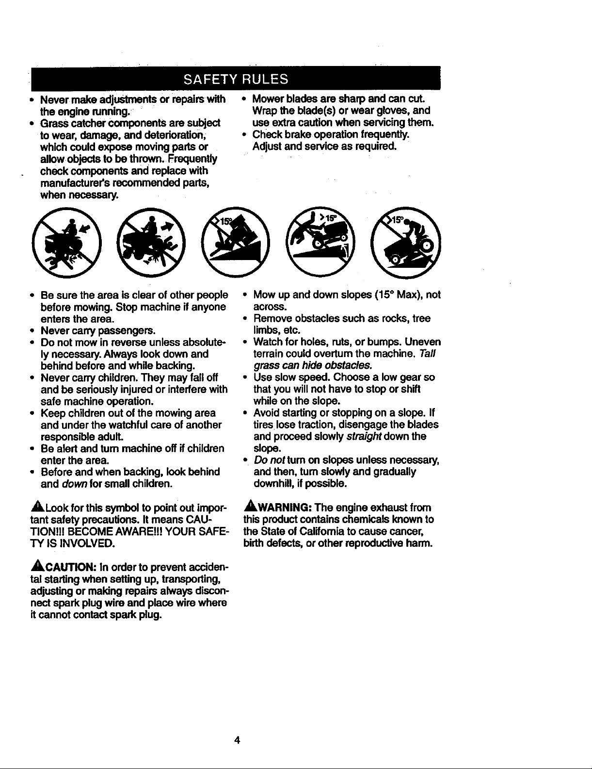
• Never make adjustments or repairs with
the engine running.
• Grass catcher components are subject
to wear, damage, and detedoration,
which couldexpose moving pads or
allow objectsto be thrown. Frequently
check components and replace with
manufacturer's recommended parts,
when necessary.
• Mower blades are sharp and can cut.
WraptheMade(s)orweargloves,and
use extra caution when servicing them.
• Check brake operstion frequently.
Adjust and service as required.
• Be sure the area is clear of other people
before mowing. Stop machine if anyone
enters the area.
• Never carry passengers.
• Do not mow in reverse unless absolute-
ly necessary. Always look down and
behind before and while backing.
• Never carry children. They may fall off
and be seriously injured or interfere with
safe machine operation.
• Keep children out of the mowing area
and under the watchful care of another
responsible adult.
• Be alert and tum machine off if children
enter the area.
• Before and when backing, look behind
and down for small children.
,_Look forthis symbol to point out impor-
tant safety precautions. It means CAU-
TIONlt! BECOME AWARE!!! YOUR SAFE-
TY IS INVOLVED.
_,CAUTION: In order to prevent acciden-
tal startingwhen setting up, transporting,
adjusting or making repairs always discon-
nect spark plug wire and place wire where
it cannot contact spark plug.
• Mow up and down slopes (15 ° Max), not
across.
• Remove obstacles such as rocks, tree
limbs, etc.
• Watch for holes, ruts, or bumps. Uneven
terrain could overtum the machine. Tall
grass can hide obstacles.
• Use slow speed. Choose a low gear so
that you will not have to stop or shift
while on the slope.
• Avoid starting or stopping on a slope. If
tires lose traction, disengage the blades
and proceed slowly straight down the
slope.
• Do nottum on slopes unless necessary,
and then, tum slowly and gradually
downhill, if possible.
_,WARNING: The engine exhaust from
this product contains chemicals known to
the State of Caiifomia to cause cancer,
birth defects, or other reproductive harm.
4

PRODUCT SPECIFICATIONS
GASOLINE 3.5 GALLONS
CAPACITY UNLEADED
AND TYPE: REGULAR
OILTYPE SAE 10W-30
API-SF/SG/SH): (above32°F)
SAE 5W-30
(below32_F)
OILCAPACITY: W/FILTER: 4.2 PINTS
W/O FILTER: 3.7 PINTS
SPARK PLUG: ChampionRC12YC
GAP: .040")
GROUND SPEED
(MPH):
REVERSE: 0.9 2.1
TIRE PRESSURE: FRONT." 14 PSI
CHARGING
SYSTEM: 15AMPS@ 3600 RPM
BATI'ERY: AMP/HR: 35
BLADE BOLT 27-35 FT. LBS.
TORQUE:
CONGRATULATIONS on your purchase
of a Craftsman Tractor. It has been
designed, engineered and manufactured
to give you the best possible dependability
and performance.
Should you experience any problem you
cannot easily remedy, please contact your
nearest Sears Authorized Service Center.
HI: LO:
0.7 1.7
1,4 3.3
2.3 5.4
REAR: 10 PSI
MIN. CCA: 280
CASE SIZE: U1R
We have competent, well-trained techni-
cians and the proper tools to service or
repair this tractor.
Please read and retain this manual. The
instructions will enable you to assemble
and maintain your tractor properly. Always
observe the =SAFETY RULES'.
MAINTENANCEAGREEMENT
A Sears Maintenance Agreement is avail-
able on this product. Contact your nearest
Sears storefor details.
CUSTOMER RESPONSIBILITIES
• Read and observe the safety rules.
• Follow a regular schedule in maintain-
ing, caring for and using your tractor.
• Follow the instructions under =Mainte-
nance" and =Storage" sections of this
owner's manual.
,_,WARNING: This tractor is equipped
with an intemal combustion engine and
should not be used on or near any unim-
proved forest-covered, brush-covered or
grass-covered land unless the engine's
exhaust system is equipped with a spark
arrester meeting applicable local or state
laws (if any). If a spark arrester is used, it
should be maintained in effective working
order by the operator.
In the state of California the above is
required by law (Section 4442 of the
California Public Resources Code). Other
states may have similar laws. Federal
laws apply on federal lands. A spark
arrester for the muffler is available through
your nearest Sears Authorized Service
Center (See REPAIR PARTS section of
this manual).
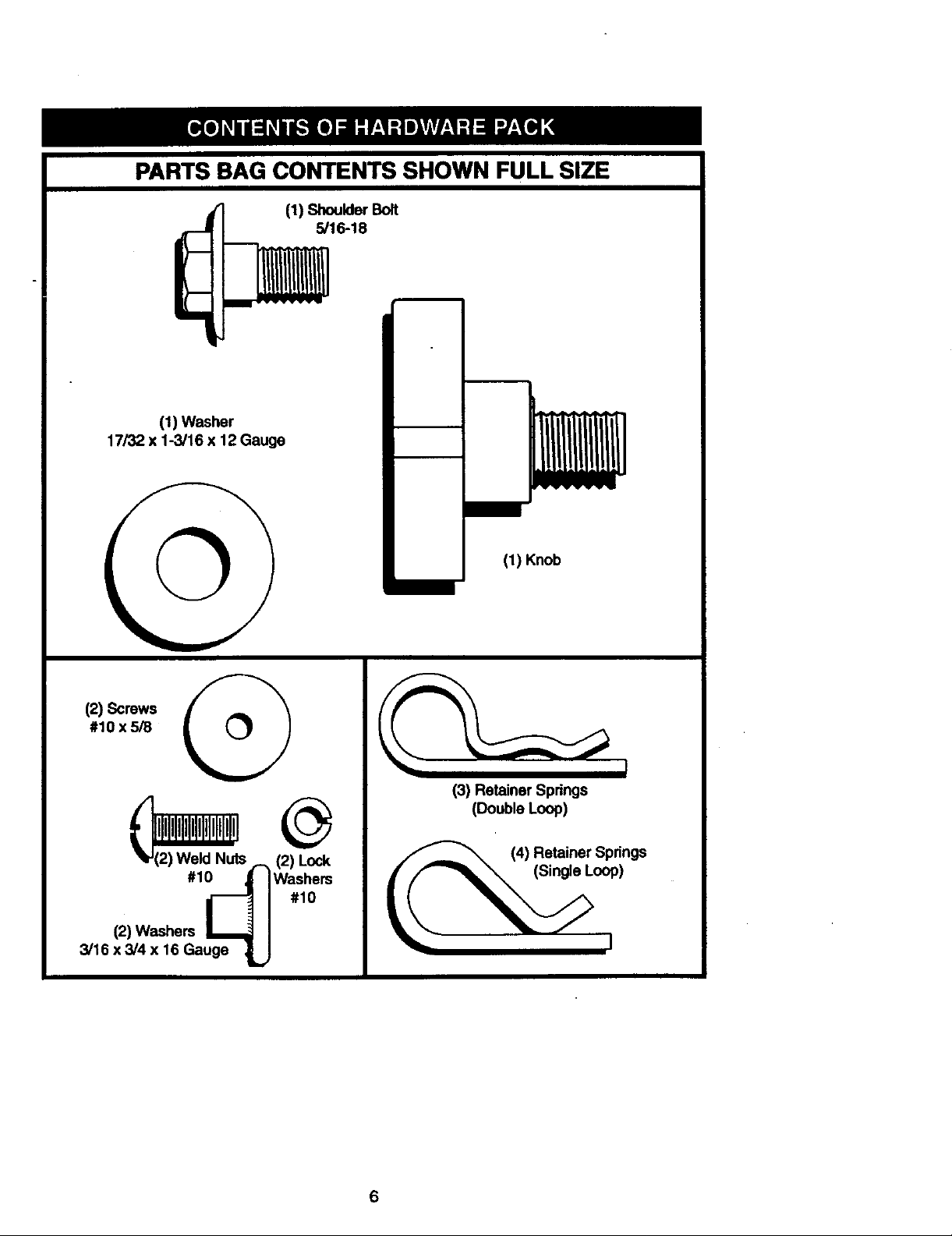
PARTS BAG CONTENTS SHOWN FULL SIZE
(1) Shoulder
5/16-18
I
m m
i
(1) Washer
17/32 x 1-3/16 x 12 Gauge
(1) Knob
#1oxs/8 q
(2) Screws
l k ,2) Weld Nuts - (
#1_ Washers#10
(2)Washers J_
3/16 x 3/4 x 16 Gauge _.,
(3) Retainer Springs
(Double Loop)
(4) Retainer Springs
f//'-'_ (Single Loop)
6

Partspacket separately In carton Parts Bag contentsnot shown full size
Jl___jL,
[-1
Video
Cassette
Mulcher
Plate
Seat
Steodng
Wheel Insert
<4€
(2) Keys
Steering Wheel
Slope Sheet
Steermg
_eeve
Extension
(2) Front Unk
Assemblies
f_)(2) Latch Hook
Assembfies
i.
Parts Bag
f
• (4) Adjusting Bar
Manual-
• @
jo (4) Wheels
(4) Retainer Springs
(4) Clevis Pins
(4) Washers 3/8 x 3/4-14
®
(4)Locknut 3/8-16 (4) Shoulder Bot
7
Yournew tractor has been assembled at the factorywith exception of those parts left
unassembled for shippingpurposes. Toensure safe and proper operation of your tractor
all parts and hardware you assemble must be tightened securely. Use the correcttools
as necessary to insure proper tightness. Review the video cassette before you begin.
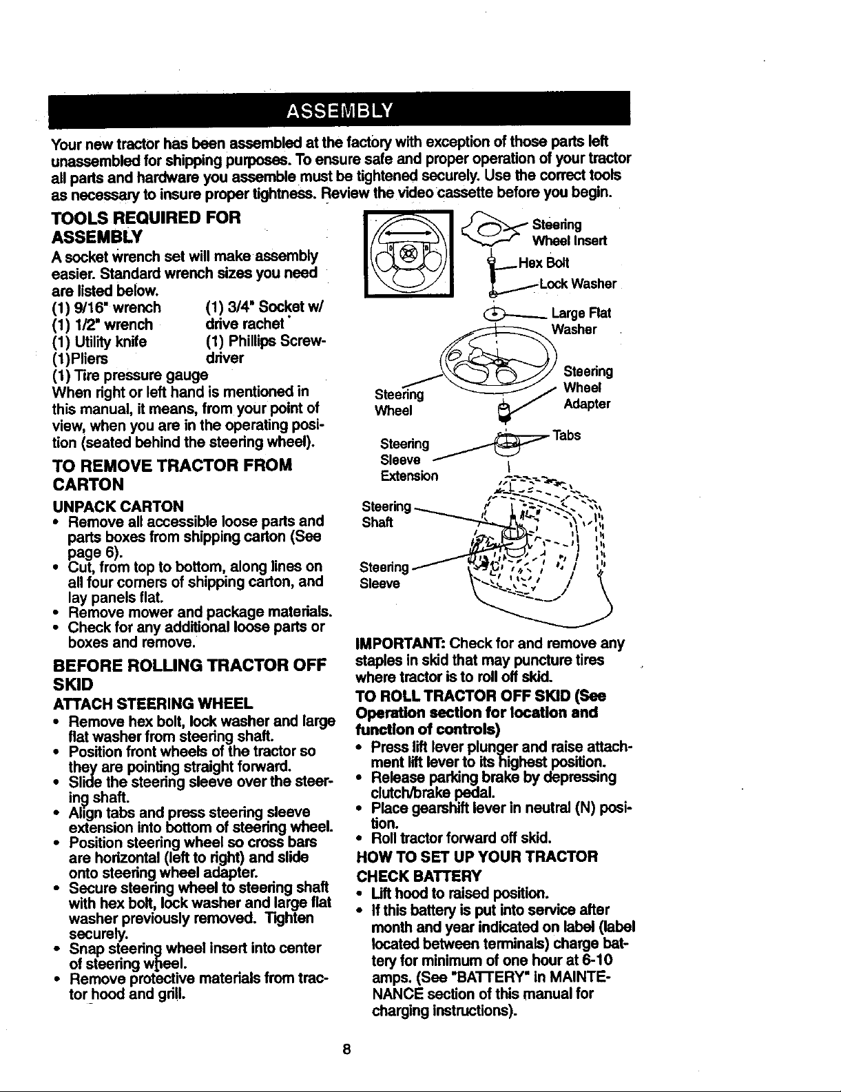
TOOLS REQUIRED FOR
ASSEMBLY
Wheel Insert
A socket wrench sot will make assembly
easier. Standard wrench sizes you need
are listed below.
(1) 9/16" wrench (1) 3/4" Socket w/
(1) 1/2" wrench drive rachet"
_..... Hex Bolt
_Tp_- LockWasher
Large Rat
Washer
(1) Utilityknife (1) PhillipsScrew-
(1)Pliers driver
(1) Tire pressure gauge
When rightor left hand is mentioned in
this manual, itmeans, from your pointof
Steering Wheel
Wheel Adapter
Steedng
view, when you are in the operating posi-
tion (seated behind the steering wheel).
TO REMOVE TRACTOR FROM
CARTON
UNPACK CARTON
• Remove all accessible loose parts and
parts boxes from shipping carton (See
page 6).
• Cut, from top to bottom, along lines on
all four comers of shipping carton, and
lay panels flat.
• Remove mower and package materials.
Check for any additional loose parts or
boxes and remove.
BEFORE ROLLING TRACTOR OFF
SKID
ATTACH STEERING WHEEL
• Remove hex bolt,lock washer and large
flat washer from steering shaft.
• Position front wheels of the tractor so
they are pointing straight forward.
• Slide the steering sleeve over the steer-
ing shaft.
• Align tabs and press steering sleeve
extension into bottom of steering wheel.
• Position steering wheel so cross bars
are horizontal (left to right) and slide
onto steering wheel adapter.
• Secure steering wheel to steering shaft
with hex bolt, lock washer and large flat
washer previously removed. Tighten
securely.
• Snap steering wheel insert intocenter
of steering wtzeel.
• Remove protective materials from trac-
tor_hoodand grill.
Steering_ Tabs
Sleeve I
Extension
Shaft
Steedng
Sleeve
IMPORTANT: Check forand remove any
staples inskid that may puncturetires
where tractor isto rolloft skid.
TO ROLL TRACTOR OFF SKID (See
Operation section for location and
function of controls)
ment liftlever to itshighest position.
Release parking brake by depressing
Press lift lever plunger and raise attach-
clutch/Drakepedal.
Place gearshift lever in neutral (N) posi-
tion.
• Rolltractor forward off skid.
HOW TO SET UP YOUR TRACTOR
CHECK BATTERY
• Lifthood to raised position.
• If this battery is put into service after
monthand year indicated on label (label
located between terminals) charge bat-
tery for minimum of one hour at 6-10
amps. (See "BATTERY" in MAINTE-
NANCE sectionof this manual for
charginginstructions).
8
_" ooO w
oOO
°'..;
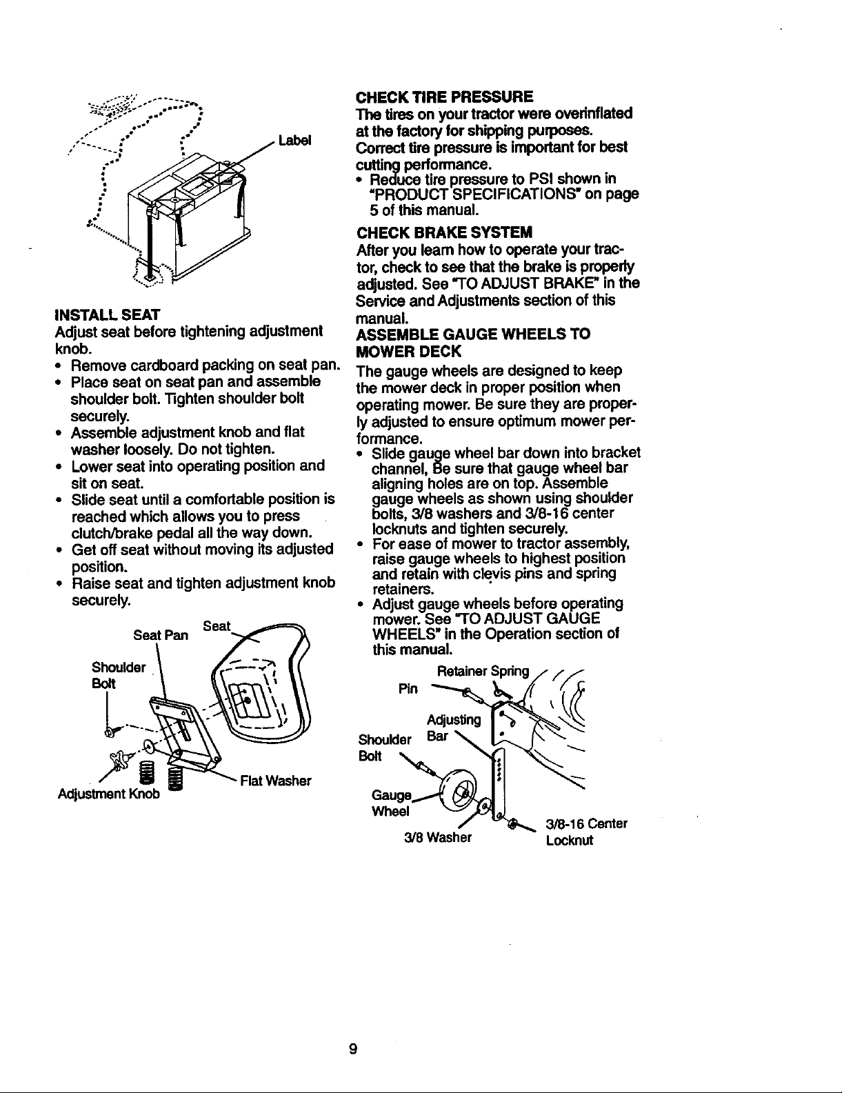
INSTALL SEAT
Adjust seat before tightening adjustment
knob.
• Remove cardboard packing on seat pan.
• Place seat on seat pan and assemble
shoulder bolt. Tighten shoulder bolt
securely.
• Assemble adjustment knob and fiat
washer loosely. Do not tighten.
• Lower seat into operating position and
sit on seat.
• Slide seat until a comfortable position is
reached which allows you to press
clutch/brake pedal all the way down.
• Get off seat without moving its adjusted
position.
• Raise seat and tighten adjustment knob
securely.
Seat Pan
Seat
Shoulder
Bo;t
CHECK TIRE PRESSURE
The tires on your tractor were ovefinflated
at the factory for shippingpurposes.
Correct tire pressure is importantfor best
cuttingperformance.
• Reduce tire pressure to PSI shown in
PRODUCT SPECIFICATIONS" on page
5 of this manual.
CHECK BRAKE SYSTEM
After you learn how to operate your trac-
tor, check to see that the brake isproperly
adjusted. Sea "TOADJUST BRAKE" in the
Service and Adjustmentssection of this
manual.
ASSEMBLE GAUGE WHEELS TO
MOWER DECK
The gauge wheels are designed to keep
the mower deck in proper position when
operating mower. Be sure they are proper-
ly adjusted to ensure optimum mower per-
formance.
• Slide gauge wheel bar down into bracket
channel, Be sure that gauge wheel bar
aligning holes are on top. Assemble
gauge wheels as shown using shoulder
bolts, 3/8 washers and 3/8-16 center
Iocknuts and tighten securely.
• For ease of mower to tractor assembly,
raise gauge wheels to highest position
and retain with clevis pins and spring
retainers.
• Adjust gauge wheels before operating
mower. See "TO ADJUST GAUGE
WHEELS" in the Operation section of
this manual.
Retainer Spdng
Pin
Adjustment Knob
AdjusUng
Shoulder Bar
Bolt
Flat Washer
Wheel
3/8-16 Center
3/8 Washer Lockout
9

INSTALLMOWERANDDRIVEBELT
Besuretractorison levelsurfaceand
mowersuspensionarmsareraisedwith
attachmentliftcontrol.Engageparking
brake.
• Cutandremovetiessecuringanti-sway
barandbelts. Swinganti-swaybarto
leftsideofmower deck.
• Slide mower under tractor with dis-
charge guard to right side of tractor.
IMPORTANT: Chock belt for proper rout-
ing in all mower pulley grooves. Install
belt into electric clutch pulley groove.
• Install one front link in top hole of the
left hand front mower bracket and left
hand front suspension bracket. Retain
with two single loop retainer springs as
shown.
• Install second front link in right hand
front suspension bracket only and retain
with single loop retainer spring as
shown.
• Slide right side of mower back and
install link in top hole of right hand front
mower bracket. Retain with single loop
retainer spring as shown.
•Tum height adjustment knob counter-
clockwise until it stops.
• Lower mower linkage with attachment
lift control.
• Place the suspension arms on inward
pointing deck pins. If necessary, rock
and raise front of mower to align dock
pins with the holes in suspension arms.
Retain With double loop retainer spring
with loops down as shown.
• Connect anti-sway bar to chassis brack-
et under left footrest and retain with
double loop retainer spring.
•Tum height adjustment knob clockwise
to remove slack from mower suspen-
sion.
• Raise dock to highest position.
• Adjust gauge wheels before operating
mower as shown in the Operation sec-
tion of this manual.
CHECK MOWER LEVELNESS
For best cutting results, mower should be
propedy leveled. See "TO LEVEL
MOWER HOUSING" in the Service and
Adjustments section of this manual.
CHECK FOR PROPER POSITION OF
ALL BELTS
See the figures that are shown for replac-
ing motion, mower drive, and mower
blade drive belts in the Service and Ad-
justments section of this manual. Verify
that the belts are routed correctly.
Wheel
Chassis
Bracket
Double Loop
Retainer Spring
(Inward pointing
deck Front Mower
Double Loop
RetainerSp.ring
Anti-Sway
Bar
Suspension Front
Arms
Pulley
10
Brackets
Retainer Springs
Discharge Guard
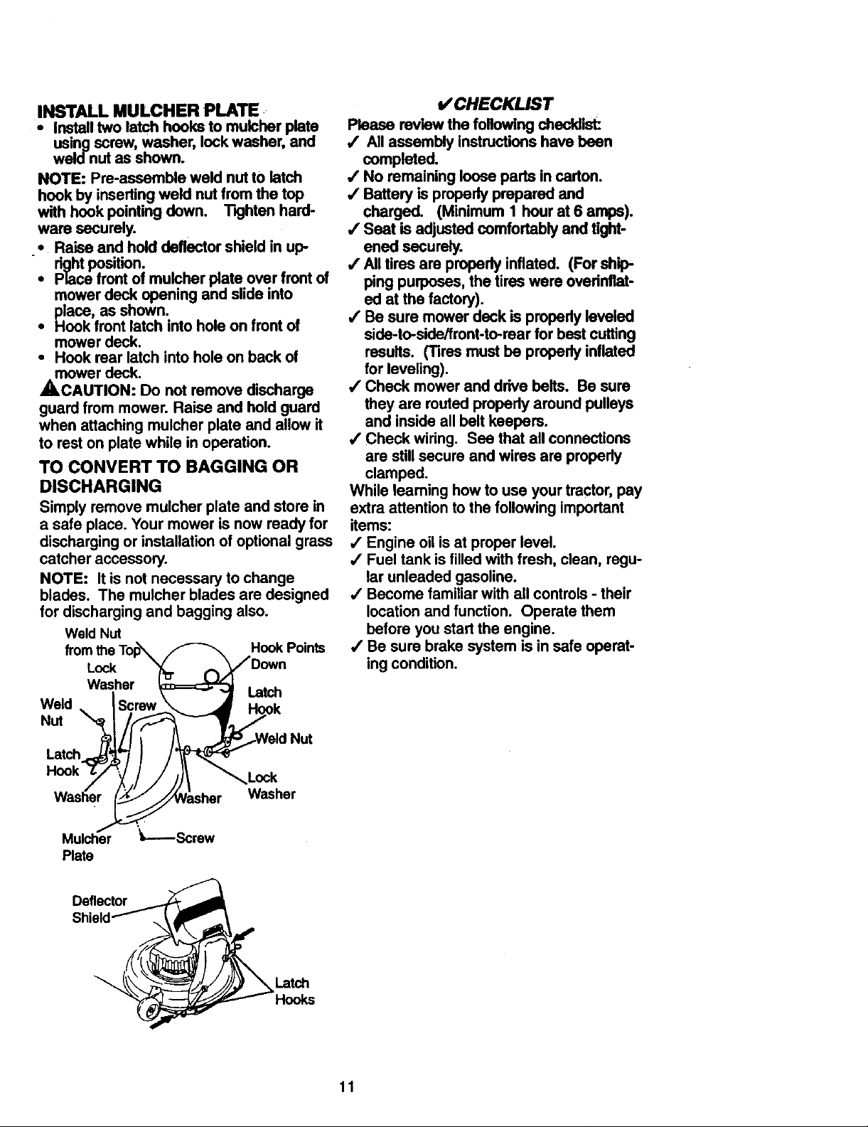
INSTALL MULCHER PLATE
• Install two latch hooks to mulcher plate
using screw,washer, lockwasher, and
weldnut as shown.
NOTE: Pre-assemble weld nut to latch
hook by inserting weld nut from the top
with hook pointing down. Tighten hard-
ware securely.
.• Raise and hold deflector shield in up-
rightposition.
• Place front of mulcher plate over front of
mower deck opening and slide into
place, as shown.
• Hook front latch into hole on front of
mower deck.
• Hook rear latch into hole on back of
mower deck.
,_,CAUTION: Do not remove discharge
guard from mower. Raise and hold guard
when attaching mulcher plate and allow it
to rest on plate while in operation.
TO CONVERT TO BAGGING OR
DISCHARGING
Simply remove mulcher plate and store in
a safe place. Your mower is now ready for
discharging or installation of optional grass
catcher accessory.
NOTE: It is not necessary to change
blades. The mulcher blades are designed
for discharging and bagging also.
Weld Nut
Hook Points
Lock
Washer Latch
Weld
Nut
Nut
Latch
L.ock
Washer
v"CHECKLIST
Please review the fogowing checldist:
/ All assembly instructions have been
completed.
/ No remaining loose parts in carton.
•f Battery is properly prepared and
charged. (Minimum 1 hour at 6 amps).
,f Seat is adjusted comfortably and tight-
ened securely.
/ All tires are propedy inflated. (For ship-
ping purposes, the tires were ovednflat-
ed at the factory).
/ Be sure mower deck is propedy leveled
side-to-side/front-to-rear for bast cuffing
results. (Tires most be properly inflated
for leveling).
,/Check mower and drive belts. Be sure
they are routed properly around pulleys
and inside all belt keepers.
/ Check wiring. See that all connections
are still secure and wires are propedy
clamped.
While leaming how to use your tractor, pay
extra attention to the following impodant
items:
/ Engine oil is at proper level.
,f Fuel tank is filled with fresh, clean, regu-
lar unleaded gasoline.
,/Become familiar with all controls - their
location and function. Operate them
before you start the engine.
/ Be sure brake system is in safe operat-
ing condition.
Mulcher "Z----Screw
Plate
Deflector
Latch
Hooks
11

These symbols may appear on your tractoror in literaturesupplied with the product.
Leam and understand their meaning.
BATrERY CAUTIONOR REVERSE FORWARD FAST SLOW
WARNING
ENG,NEO"ENG,NEOFEO,LPRE=OREUGHTSONOVI,_O_P
FUEL CHOKE MOWER HEIGHT PARKING BRAKE UNLOCKED MOWER LIFT
LOCKED
R N H L
ATTACHMENT REVERSE NEUTRAL HIGH LOW PARKING BRAKE
CLUTCH ENGAGED
ATTACHMENT
IGNITION CLUTCH DISENGAGED (SEE SAFETY RULES SECTION)
DANGER,KEEP HANDSAND FEETAWAY
KEEP AREA CLEAR SLOPE HAZARDS
FREEWHEEL
(AutomaticMod_ o_)
12
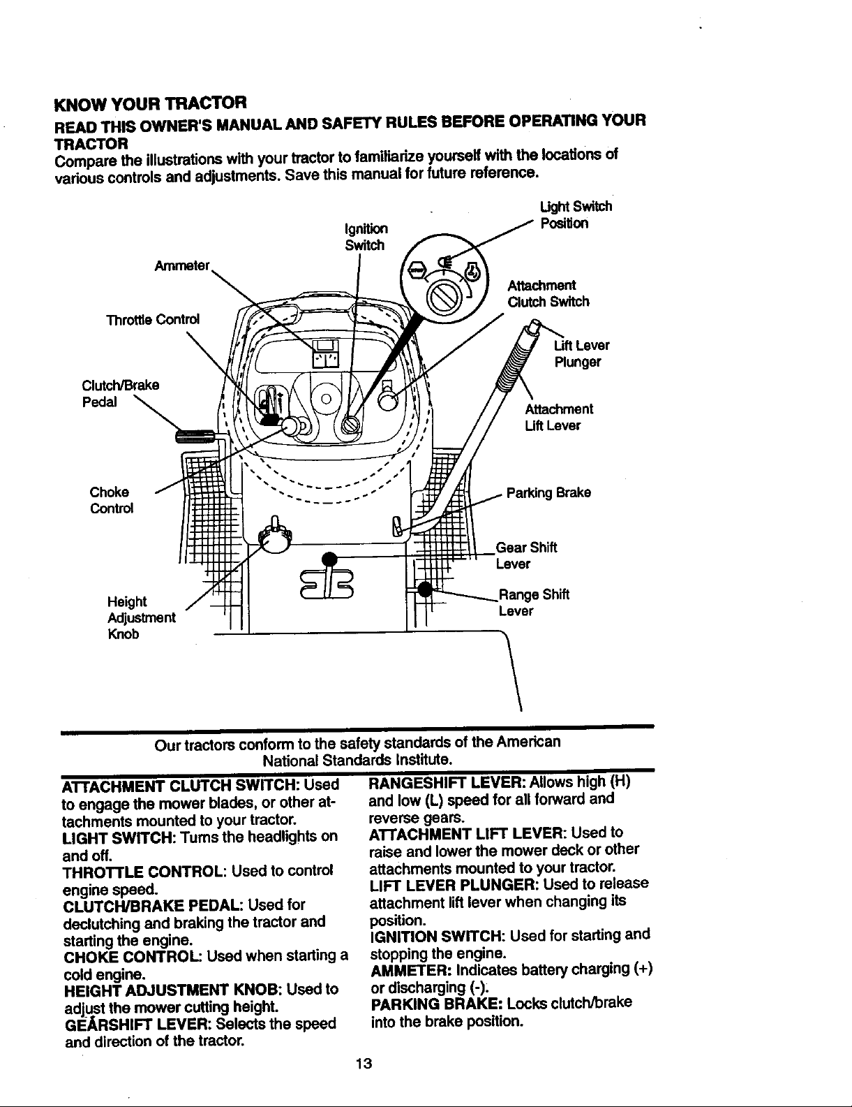
KNOW YOUR TRACTOR
READTHISOWNER'SMANUALANDSAFETYRULESBEFOREOPERATINGYOUR
TRACTOR
Comparethe illustrationswithyourtractortofamiliarizeyourselfwiththelocationsof
variouscontrolsandadjustments.Savethismanualforfuturereference.
UghtSwitch
Ignition
Posi_on
Switch
Ammeter
Attachment
ThrottleControl
Clutch/Brake
Pedal
Choke Parking Brake
Control
Clutch Switch
LiftLever
Plunger
Attachment
Lift Lever
Height e Shift
Adjustment Lever
Knob
Our tractors conformto the safety standards of the American
National Standards institute.
ATTACHMENT CLUTCH SWITCH: Used
to engage the mower blades, or other at-
tachments mounted to your tractor.
LIGHT SWITCH: Turns the headlights on
and off.
THROTTLE CONTROL: Used to control
engine speed.
CLUTCWBRAKE PEDAL: Used for
declutching and braking the tractor and
starting the engine.
CHOKE CONTROL: Used when starting a
cold engine.
HEIGHT ADJUSTMENT KNOB: Used to
adjust the mower cutting height.
GEARSHIFT LEVER: Selects the speed
and direction of the tractor.
Gear Shift
Lever
1
RANGESHIFT LEVER: Allows high (H)
and low (L) speed for all forward and
reverse gears.
ATTACHMENT LIFT LEVER: Used to
raise and lower the mower deck or other
attachments mounted to your tractor.
LIFT LEVER PLUNGER: Used to release
attachment liftlever when changing its
position.
IGNITION SWITCH: Used for starting and
stopping the engine.
AMMETER: Indicates battery charging (+)
or discharging (-),
PARKING BRAKE: Locks clutch/brake
into the brake position.
13

Theoperationofanytractorcanresultinforeignobjectsthrownintothe
eyes, which can result in severe eye damage. Always wear safety glasses
or eye shields while operating your tractor or performing any adjustments or
repairs. We recommend a wide vision safety mask over spectacles, or stan-
dard safety glasses.
HOW TO USE YOUR TRACTOR
Your tractor is equipped with an operator
* presence sensing switch. When engine is
running,any attempt by the operator to
leave the seat without first settingthe
parkingbrake will shut off the engine.
TO SET PARKING BRAKE
• Depress clutch/brake pedal into full
"BRAKE" position and hold.
• Place parking brake lever in "EN-
GAGED" position and release pressure
from clutch/brake pedal. Pedal should
remain in "BRAKE" position. Make sure
parking brake will hold tractor secure.
Throttle Push-In to Attachment Clutch
Control =Disengaged" Switch PullOut To
_age" _...,,_
_ ""['_ Control _-._-_-_Parking Brake
Clu_h/Bmke ";Disengaged;"
Pedal "Ddve" Position
Position
STOPPING
MOWER BLADES -
• To stop mower blades, move attach-
ment clutch switch to "DISENGAGED"
position.
GROUND DRIVE -
• To stop ground drive, depress
clutch/brake pedal into full "BRAKE" po-
sition.
• Move gearshift lever to neutral (N) posi-
tion.
ENGINE -
• Move throttle control to slow position.
NOTE: Failure to move throttle control to
slow position and allowing engine to idle
before stopping may cause engine to
"backfire'.
• Tum ignition key to =OFF" position and
remove key. Always remove key when
leaving tractor to prevent unauthorized
USa.
• Never use choke to stop engine.
IMPORTANT: Leaving the ignition switch
in any position other than "OFF" will cause
the battery to be discharged, (dead).
NOTE: Under cedain conditions when
tractor is standing idle with the engine run-
ning, hot engine exhaust gases may
cause "browning" of grass. To eliminate
this possibility, always stop engine when
stopping tractor on grass areas.
,A CAUTION: Always stop tractor com-
pletely, as deecdbed above, before leaving
the operator's position; to empty grass
catcher, etc.
THRO'i-rLE CONTROL
Always operate engine at full throttle.
• Operating engine at less than full throt-
tle reduces the battery charging rate.
• Full throttle offers the best bagging and
mower performance.
CHOKE CONTROL
Use choke control whenever you are start-
ing a cold engine. Do not use to start a
warm engine.
• To engage choke control, pull knob out.
Slowly push"knob in to disengage.
TO MOVE FORWARD AND BACKWARD
The direction and speed of movement is
controlled by the gearshift lever.
• Start tractor with clutch/brake pedal
depressed and gearshift lever in neutral
(N)position.
• Move gearshift and range shift levers to
desired position.
• Slowly release clutch/brake pedal to
start movement.
IMPORTANT: Bring tractor to a complete
stop before shifting or changing gears.
Failure to do so will shorten the useful life
of your transaxle.
TO ADJUST MOWER CUTTING HEIGHT
The cutting height is controlled by tum-
ing the height adjustment knob in
desired direction.
• Tum knob clockwise (G) to raise cutting
height.
14

• Tum knob counterclockwise(0)to
lowercuttingheighL
Thecuttingheightrangeis approximately
1-1/2"to4-1/2".Theheightsaremea-
suredfromthegroundtothe bladetipwith
theenginenotrunning.Theseheightsare
approximateandmayvarydepending
.uponsoilconditions,heightof grassand
typesofgrassbeingmowed.
• The averagelawnshouldhe cut to
approximately 2-1/2 inchesduringthe
cool season and to over 3 inches during
hot months. For healthier and better
looking lawns, mow often and after
moderate growth.
• For best cutting performance, grass
over 6 inches in height should be
mowed twice. Make the first cut rela-
tively high; the second to desired height.
TO ADJUST GAUGE WHEELS
Gauge wheels are properlyadjusted
when they are slightly off the ground when
mower is at the desired cutting heightin
operating position.Gauge wheels then
keep the deck in proper positionto help
prevent scalping in most terrain condi-
tions.
• Be sure tractor is on a flat level surface.
• Lower mower and adjust mower to
desired cutting height.
• Remove retainer spring and clevis pin
which secure each gauge wheel bar.
• Lower gauge wheels to ground. Raise
gauge wheels slightlyto align holes in
bracket and gauge wheel bar and insert
clevis pin. Gauge wheels should be
slightly oftthe ground.
presence sensing switch. Any attempt by
the operator to leave the seat with the
engine runningand the attachment dutch
engaged will shutoffthe engine.
• Select desired height of cut.
• Lower mower with attachment lift con-
troL
• Start mower blades by engaging attach-
mant dutch control.
• TO STOP MOWER BLADES - disen-
gage atta(_hmentclutchcontrol.
AttachmentClutch
Switch Pull
Attacl'mlent Lift Lever
High Position
...,tLOW
H P_
;/
Discharge
Guard
"Disengage"
,_CAUTION: Do not operate the mower
without either the entire grass catcher, on
mowers so equipped, or the discharge
guard in place.
TO OPERATE ON HILLS
_.CAUTION: Do not drive up or down
hills with slopes greater than 15° and do
not drive across any slope. Use the slope
guide provided at the back of this manual.
• Choose the slowest speed before start-
ing up or down hills. .
• Avoidstopp,ng or changing speed on
hills.
• If slowing is necessary, move throttle
control lever to slower position.
Retainer spring
Clevis Pin
• Replace retainer spring into clevis pin.
IMPORTANT: Be sure to readjust gauge
wheels if you change the cutting height of
the mower deck.
TO OPERATE MOWER
Your tractor is equipped with an operator
clutch/brake pedal quickly to brake posi-
i f stoppingis absolutely necessary, push
tion and engage parking brake.
Move gearshift lever to 1st gear and
range shift lever to low (L) position. Be
sure you have allowed room for tractor
to rolislightly as you restart movement.
parking brake and clutch/brake pedal.
i o restart movement, slowly release
Make all tums slowly.
TO TRANSPORT
• Raise attachment lift to highest position
with attachment lift control.
• When pushing or towing your tractor, be
sure gearshift lever is in neutral (N)
position.
° Do not push or tow tractor at more than
five (5) MPH.
NOTE: To protect hood from damage
15

when transportingyour tractoron.at.nJok
or a trailer, be sure hood is closeo ana
secured to tractor. Use an appropriate
means of tying hood to tractor (rope, cord,
etc.).
TOWING CARTS AND OTHER
ATTACHMENTS
Tow on y the attachments that are recom-
mended by and comply withspecifications
ofthe manufacturer of your tractor. Use
common sense when towing. Too heavy of
a load, while on a slope, is dangerous.
Tires can lose traction withthe ground and
cause you to lose control ofyour tractor.
BEFORE STARTING THE ENGINE
CHECK ENGINE OIL LEVEL
• The engine in your tractor has been
shipped, from the factory, already filled
with summer weight oil.
• Check engine oil with tractor on level
ground.
• Unthread and remove oil fill cap/dip
stick; wipe oil off. Reinsert the dipstick
into the tube and rest oil fill cap on the
tube. Do not thread the cap onto the
tube. Remove and read oil level. If nec-
essary, add oil until "FULL" mark on
dipstick is reached. Do not overfill.
• For cold weather operation you should
change oil for easier starting (See "OIL
VISCOSITY CHART" in the Customer
Responsibilities section of this manual).
• To change engine oil, see the Customer
Responsibilities section in this manual.
ADD GASOLINE
• Fill fuel tank. Use fresh, clean, regular
unleaded gasoline with a minimum of 87
octane. (Use of leaded gasoline will
increase carbon and lead oxide
deposits and reduce valve life). Do not
mix oil with gasoline. Purchase fuel in
quantitiesthat can be used within 30
days to assure fuel freshness.
IMPORTANT: When operating in tsmpora-
tunasbelow 32°F(0°C), use fresh, clean
winter grade gasoline to help insure good
_vAweather starting.
RNING: Experience indicates that
alcohol blended fuels (called gasohol or
using ethanol or methanol) can attract
moisture which.leeds to separation and
formation of acids dudng storage. Acidic
gas can damage the fuel system of an
engine while in storage. To avoid engine
problems, the fuel system should be emp-
tied before storage of 30 days or longer.
Drain the gas tank, start the engine and let
it run until the fuel lines and carburetor are
empty. Use fresh fuel next season. See
Storage Instructions for additional
information. Never use engine or
carburetor cleaner products in the fuel
t_k or permanent damage may occur.
CAUTION: Fill to bottom of gas tank
filler neck. Do not overfill. Wipe off any
spilled oil or fuel. Do not store, spill or use
gasoline near an open flame.
TO START ENGINE
When starting the engine for the first time
or if the engine has run out of fuel, it will
take extra cranking time to move fuel from
the tank to the engine.
• Sit on seat in operating position,
depress clutch/brake pedal and set
parking brake.
• Place gear shift lever in neutral (N)
position.
• Move attachment clutch to "DISEN-
GAGED" position.
• Move throttle control to fast position
• Pull choke control out for a cold engine
start attempt. For a warm engine start
attempt the choke control may not be
needed.
NOTE: Before starting, read the warm and
cold starting procedures below.
• Insert key into ignition and turn key
clockwise to "START" position and
release key as soon as engine starts.
Do not run starter continuously for more
than fifteen seconds per minute. If the
engine does not start after several
attempts, push choke control in, wait a
few minutes and try again. If engine still
does not start, pull the choke control out
and retry.
WARM WEATHER STARTING (50 ° F
AND ABOVE)
• When engine starts, slowly push choke
control in until the engine begins to run
smoothly. If the engine starts to run
roughly, pull the choke control out slight-
ly for a few seconds and then continue
16
topushthecontrolin slowly.
• The attachmentsandgrounddrivecan
nowbeused.Iftheenginedoesnot
accepttheload,restarttheengineand
allowit towarmupforoneminute using
the choke as described above.
COLD WEATHER STARTING (50* F AND
BELOW)
• When engine starts, slowly push choke
control in until the engine begins to run
smoothly. Continue to push the choke
control in small steps allowing the
engine to accept small changes in
speed and load, until the choke control
is fully in. If the engine starts to run
roughly, pull the choke control out slight-
ly for a few seconds and then continue
to push the control in slowly, This may
require an engine warm-up pedod from
several seconds to several minutes,
depending on the temperature.
• The attachments can be used dudng
the engine warm-up pedod and may
require the choke control be pulled out
slightly.
NOTE: A high altitude (above 3000 feet)
or in cold temperatures (below 32 F) the
carburetor fuel mixture may need to be
adjusted for best engine performance.
See "TO ADJUST CARBURETOR" in the
Service and Adjustments section of this
manual.
• Drive so that clippings are discharged
onto the area that has been cut. Have
the cut area to the dght of the tractor.
This will result in a more even distribu-
tionof clippings and more uniformcut-
ting.
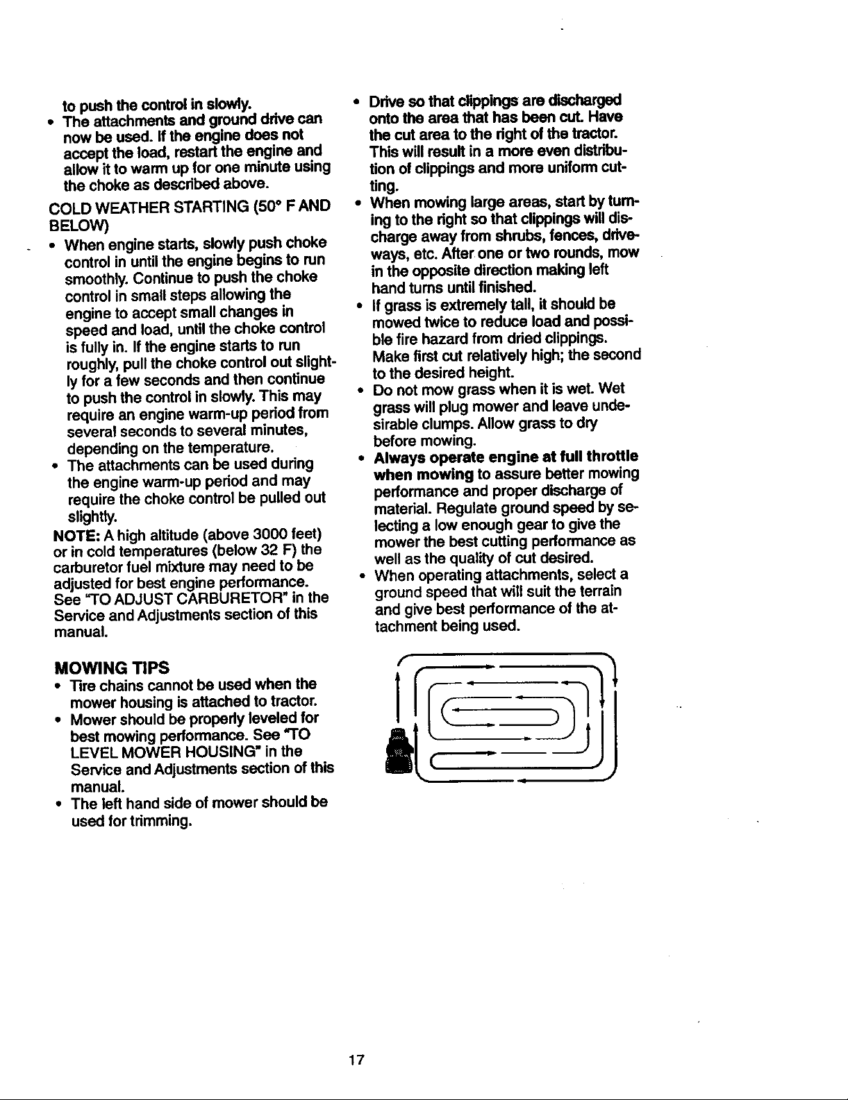
• When mowing large areas, start by turn-
ing tothe dght so that clippingswilldis-
charge away from shrubs, fences, drive-
ways, etc. After one ortwo rounds, mow
in the opposite direction making left
hand tums untilfinished.
• If grass is extremely tall, it should be
mowed twice to reduce load and possi-
ble fire hazard from dried clippings.
Make first cut relatively high;the second
to the desired height.
• Do not mow grass when itis wet. Wet
grass will plug mower and leave unde-
sirable clumps.Allow grass to dry
before mowing.
• Always operate engine at full throttle
when mowing to assure better mowing
performance and proper discharge of
material. Regulate ground speed by se-
lectinga low enough gear to give the
mower the best cutting performance as
well as the quality of cut desired.
• When operating attachments, select a
groundspeed that will suit the terrain
and give best performance of the at-
tachment being used.
MOWING TIPS
• Tire chains cannot be used when the
mower housing isattached to tractor.
• Mower should be properly leveled for
best mowing performance. See "TO
LEVEL MOWER HOUSING" in the
Service and Adjustments section of this
manual.
• The left hand side of mower should be
used for trimming.
17

MULCHINGMOWING TIPS
IMPORTANT:.Forbestperformance, keep
mower housing free of built-up grass and
trash. Clean after each use.
• The special mulching blade will recut
the grass clippings many times and
reduce them in size so that as they fall
onto the lawn they will disperse into the
grass and not be noticed. Also, the
mulched grass will biodegrade quickly
to provide nutdents for the lawn. Always
mulch with your highest engine (blade)
speed as this will provide the bast recut-
ting action of the blades.
• Avoid cuffing your lawn when it is wet.
Wet grass tends to form clumps and
interferes with the mulching action. The
best time to mow your lawn is the early
aftemoon. At this time the grass has
dried and the newly cut area will not be
exposed to the direct sun.
• For best results, adjust the mower cut-
ting height so that the mower cuts off
only the top one-third of the grass
blades. For extremely heavy mulching,
reduce your width of cut on each pass
and mow slowly.
• Certain types of grass and grass condi-
tions may require that an area be
mulched a second time to completely
hide the clippings. When doing a sec-
ond cut, mow across or perpendicular to
the first cut path.
• Change your cutting pattern from week
to week. Mow north to south one week
then change to east to west the next
week. This will help prevent matting and
graining of the lawn.
18
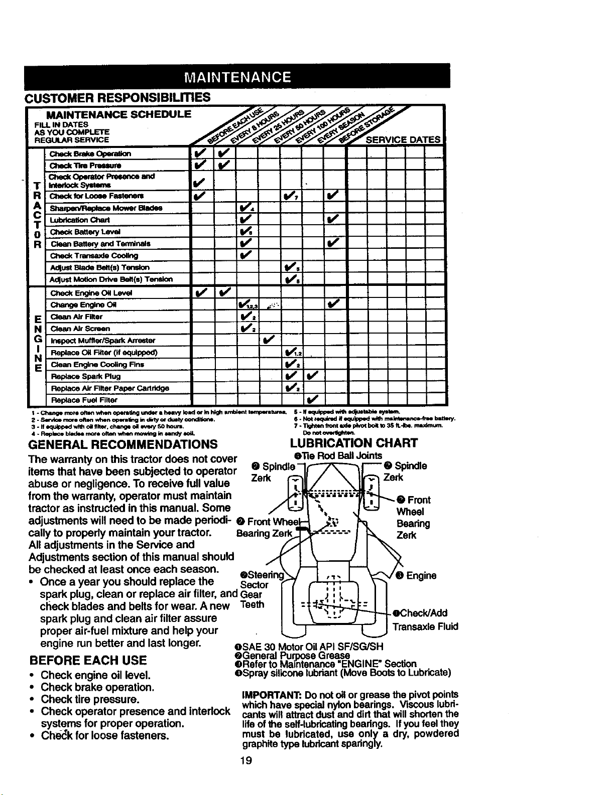
CUSTOMER RESPONSIBILmES
FILL IN DATES
AS YOU COMPLETE
MAINTENANCE SCHEDULE__ ____ES_ER_VIC*_E D
REGULAR SERVICE f_ ATES
R cm_ _xLoo_ Fastmm V* t/'7 I_
AdlustBlade Belt(s) Tension II#fs
Adjust Motion Drive Belt(s) Tension _s
E Clean Air Rlter _:
N CleanAirscreen
IG Inspect Muffler/Spark Arrester
N i Clean Engine Co_ing Firm
Replace Spark Plug _
Replace Air Filter Paper Carlddge _l_a
Replace Fue_ Filter
t. Change nlore often _en operating under i heavy k_ax:lor in high wnblent ternpem_qmL S. If equipped whh ed_J/_okp _tBm,
2..sm-_ce morn¢ltlm when opem_w_gtndin'y_ du6ty oondit_e. 6. Not _d If eo_lppodw_h m_n_mmce-_e b_m_'_'.
3. If equ_p_l with o_ filt_, dmnge oa _4e_ 50 hours. 7 ÷Tighten h_nt rode plvo_ bo_ _o 3$ ft.4be, rmudmwn.
4. _ bladesmoreoftenv,t_mmowing inundy *_. DOnoto_ghten.
GENERAL RECOMMENDATIONS LUBRICATION CHART
The warranty on this tractor does not cover e'Re Rod Ball Joints
items that have been subjected to operator • Spindle-I/,-_/_--_'_'-e Spindle
abuse or negligence. To receive full value Zerk _,_=;_ Zerk
from the warranty, operator must maintain .,/r__;_I'_"_...... _L;_ -_,_ • Front
tractor as instructed in this manual. Some / _ _ %, _ _ Wheal
adjustments will need to be made periedi- • Front Whee,_l;_ .,,_" _. Doaring
cally to properly maintain your tractor. Beadng Ze_erk
All adjustments in the Service and
Adjustments section of this manual should
be checked at least once each season, eSteadn _ I , =_ I _e Engine
• Once a year you should replace the Sector ! _ \ "1
spark plug, clean or replace air filter, and Gear I I ,; '.!;__ J I I
check blades and belts for wear. A new
spark plug and clean air filter assure
proper air-fuel mixture and help your
engine run better and last longer.
BEFORE EACH USE
• Check engine oil level.
• Check brake operation.
• Check tire pressure.
• Check operator presence and intedock
systems for proper operation.
• Ch_,_k for loose fasteners.
v'
Teeth -1:_:__ :heck/Add
_ Transaxle Ruid
OSAE 30 Motor Oil API SF/SG/SH
@General Pur_. e Grease
_Refer to Mmntenance =ENGINE" Section
eSpray siliconelubriant (Move Bootsto Lubricate)
IMPORTANT: Do not oil or grease the pivot points
which have special nylon bearings. Viscous lubri-
cants will attract dust and dirtthat willshorten the
life of the self-lubricatingbeadngs. If you feel they
must be lubdcated, use only a dry, powdered
graphite type lubflcant sparingly.
19
_A_OR
Always observe safety rules when per-
formingany maintenance.
BRAKE OPERATION
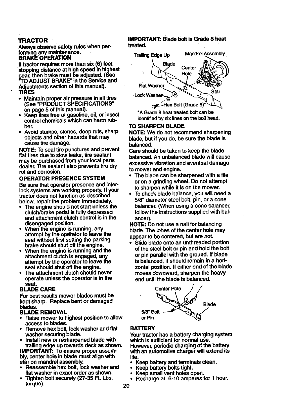
IMPORTANT: Blade bolt is Grade 8 heat
treated.
TrailingEdge Up
Mandrel Assembly
Iftractor requires more than six(6) feet
stopping distanceat highspeed in highest
gear, then brake must be adjusted. (See
"TO ADJUST BRAKE" in the Service and
Adjustments section of this manual).
TIRES
• Maintain proper air pressure in all tires
(See =PRODUCT SPECIFICATIONS"
on page 5 ofthis manual).
• Keep tires free of gasoline, oil, or insect
controlchemicals which can harm rub-
ber.
• Avoid stumps, stones, deep ruts, sharp
objects and other hazards that may
cause tire damage.
NOTE: To seal tire punctures and prevent
flat tires due toslow leaks, tire sealant
may be purchased from your local parts
dealer. Tire sealant also prevents tire dry
rot and corrosion.
OPERATOR PRESENCE SYSTEM
Be sure that operatorpresence and inter-
lock systems are working properly. Ifyour
tractor does notfunction as described
below, repair the problem immediately.
• The engine should not start unless the
clutch/brake pedal isfully depressed
and attachment clutch control is in the
disengaged position.
attempt by the operator to leave the
seat without first setting the parking
i hen the engine is running, any
brake should shut off theengine.
When the engine is running and the
attachment clutch is engaged, any
attempt by the operator to leave the
seat should shut off the engine.
• The attachment clutch should never
operate unless the operator is in the
seat.
BLADE CARE
For best results mower blades must be
kept sharp. Replace bent or damaged
blades.
BLADE REMOVAL
• Raise mower to highest position to allow
access to blades.
• Remove hex bolt, lock washer and fiat
washer securing blade.
• Install new or resharpened blade with
trailing edge up towards deck as shown. However, periodic charging of the battery
IMPORTANT: To ensure proper assem- with an automotive charger will extend its
bly, center hole in blade must ahgn with life.
star on mandrel assembly. • Keep battery and terminals clean.
• Reassemble hex bolt, lock washer and • Keep battery bolts tight.
fiat washer in exact order as shown. • Keep small vent holes open.
torque).
Rat Washer
Star
Lock Washer_
_.-._ Hex Bolt
*A Grade 8 heat treated boltcan be
identified bysix lineson the bolthead.
TO SHARPEN BLADE
NOTE: We do not recommend sharpening
blade, but if you do, be sure the blade is
balanced.
Care should be taken to keep the blade
balanced. An unbalanced blade will cause
excessive vibration and eventual damage
to mower and engine.
• The blade can be sharpened with a file
or on a grinding wheel. Do not attempt
to sharpen while it is on the mower.
• To check blade balance, you will need a
5/8" diameter steel bolt, pin, or a cone
balancer. (When using a cone balancer,
follow the instructions supplied with bal-
ancer).
NOTE: Do not use a nail for balancing
blade. The lobes of the center hole may
appear to be centered, but are not.
• Slide blade onto an unthreaded portion
of the steel bolt or pin and hold the bolt
or pin parallel with the ground. If blade
is balanced, it should remain in a hori-
zontal position. If either end of the blade
moves downward, sharpen the heavy
end until the blade is balanced.
Center Hole
Blade
5/8" Bolt
or Pin
BATTERY
Yourtractor has a battery charging system
which is sufficientfor normal use.
• Recharge at 6-10 amperes for I hour.• Tighten bolt securely (27-35 Ft. Lbs.
2O
 Loading...