

Craftsman 917273021 Owner’s Manual
Owner's Manual
CnnFTSivina
20.0 HP
ELECTRIC STAR7
46" MOWER
AUTOMATIC
GARDEN TRA C
Model No.
917.273021
• Safety
• Assembly
• Operation
• Maintenance
• Repair Parts
CAUTION:
Read and follow all
Safety Rules and Instructions
before operating this equip-
ment.
For answers to yourquestions
aboutthis product,Call:
1-800-659-5917
Sears Craftsman Help Line
5 am - 5 pm, Mort- Sat
Sears, Roebuck and Co., Hoffman Estates, IL 60179

Warranty ................................................. 2
Safety Rules ........................................... 2
Product Specifications ........................... 5
Assembly................................................ 8
Operation.............................................. 12
Maintenance Schedule ......................... 19
LIMITED TWO YEAR WARRANTY ON CRAFTSMAN RIDING EQUIPMENT
Maintenance ......................................... 19
Service and Adjustments...................... 23
Storage................................................. 31
Troubleshooting.................................... 32
Repair Parts ......................................... 36
Parts Ordering ............... ........Back Cover
•For two (2) years from the date of purchase, ifthis Craftsman Riding Equipment is main-
tained, lubricated and tuned up according to the instructionsin the owner's manual,
Sears will repair or replace, free of charge, any parts found to be defective in material or
workmanship.
This Warranty does not cover:.
• Expendable items which become wom during normal use, such as blades, spark
plugs, air cleaners, belts, etc.
• Tire replacement or repair caused bypuncturesfrom outside objects, such as nails,
thoms, stumps, or glass.
• Repairs necessary because of operator abuse, negligence, improperstorage or acci-
dent or the failureto maintain the equipment according to the instructionscontained in
the owner's manual.
• Riding equipment used for commercial or rentalpurposes.
LIMITED 90 DAYWARRANTY ON BATTERY
For ninety (90) days from date of pumhase, if any battery included with this riding equip-
ment proves defective in material or workmanship and ourtesting determines the bat-
tery will not hold a charge, Sears will replace the battery at nocharge. In-home warranty
service on your Craftsman riding equipment is available at no charge for 30 days from
the date of purchase. Please contact your nearest service center. After 30 days from the
date of purchase, warranty service is available by taking your Craftsman riding equip-
ment to your nearest Sears Service Center. (In-home warranty service willstill be avail-
able after 30 days from thedate of purchase but a standard trip charge will apply). This
warranty applies only while this product is inthe United States. This Warranty gives you
specific legal rights,and you may also have other dghts which may vary from state to
state.
Sears, Roebuck and Co., D/817 WA, Hoffman Estates, IL 60179
GENERAL OPERATION
• Read, understand, and follow all instruc-
tions in the manual and on the machine
before starting.
• Only allow responsible adults, who are
familiar with the instructions,to operate
the machine.
• Clear the area of objects such as rocks,
toys, wire, etc., which could be picked
up and thrown by the blade.
• Be sure the area is clear of other people
befOr_mowing. Stop machine if anyone
enters the area.
• Never carry passengers.
• Do not mow in reverse unless absolute-
ly necessary. Always look down.and
behind before and while backing:
• Be aware of the mower discharge direc-
tionand do not point it at anyone. Do
not operate the mower without either
the entire grasscatcher or the guard in
place.
• Slow down before tuming.
• Never leave a runningmachine unat-
tended. Always turn offblades, set park-
ing brake, stop engine, and remove
keys before dismounting.
2
• Tum off blades when not mowing.
• Stop engine before removing grass
catcher or unclogging chute.
• Mow only in daylight or good artificial
light.
• Do not operate the machine while under
the influence of alcohol or drugs.
• Watch for traffic when operating near or
crossing roadways.
• Use extra care when loadingor unload-
ing the machine into a trailer or truck.
SLOPE OPERATION
Slopes are a major factor related to Ioss-
of-contrel and tipover accidents, which
can result in severe injury or death. All
slopes requireextra caution. If you cannot
back up the slope or if you feel uneasy on
it, do not mow it.
DO:
• Mow up and down slopes, not across.
• Remove obstacles such as rocks, tree
limbs, etc.
• Watch for holes, ruts, or bumps. Uneven
terrain could overturn the machine. Tall
grass can hide obstacles.
• Use slow speed. Choose a low gear so
that you will not have to stop or shift
while on the slope.
• Follow the manufacturer's recommen-
dations for wheel weights or counter-
weights to improve stability.
• Use extra care with grass catchers or
other attachments. These can change
the stability of the machine.
• Keep all movement on the slopes slow
and gradual. Do not make sudden
changes in speed or direction.
• Avoid starting orstopping on a slope. If
tires lose traction, disengage the blades
and proceed slowly straight down the
slope.
DO NOT:
• Do nottum on slopes unless necessary,
and then, tum slowly and gradually
downhill, if possible.
• Do not mow near drop-offs, ditches, or
embankments. The mower could sud-
denly turn over if a wheel is over the
edge of a cliffor ditch, or if an edge
caves in.
• Do-not mow on wet grass. Reduced
traction could cause sliding.
• Do nottry to stabilize the machine by
puttingyour foot on the ground.
• Do not use grass catcher on steep
slopes.
CHILDREN
Tragic accidents can occur if the operator
is not alert to the presence of children.
Children are often attracted to the
machine and the mowing activity. Never
assume that children will remain where
you last saw them.
• Keep children out of the mowing area
and under the watchful care of another
responsible adulL
• Be alert and tum machine off if children
enter the area.
• Before and when backing, look behind
and down for small children.
• Never carry children. They may fall off
and be seriously injured or interfere with
safe machine operation.
• Never allow children to operate the
machine.
• Use extra care when approaching blind
comers, shrubs, trees, or other objects
that may obscure vision.
SERVICE
• Use extra care in handling gasoline and
other fuels. They are flammable and
vapors are explosive.
Use only an approved container.
Never remove gas cap or add fuel
with the engine running. Allow en-
gine to cool before refueling. Do not
smoke.
Never refuel the machine indoors.
Never store the machine or fuel
container inside where there is an
open flame, such as a water heater.
• Never run a machine inside a closed
area.
• Keep nuts and bolts, especially blade
attachment bolts, tight and keep equip-
ment in good condition.
Check their proper operation regularly.
_ Never tamper with safety devices.
Keep machine free of grass, leaves, or
other debris build-up. Clean oil or fuel
spillage. Allow machine to cool before
'storing.
• Stop and inspect the equipment if you
strike an object. Repair, if necessary,
before restarting.
3
• Never make adjustments or repairswith
the engine running.
• Grass catcher components are subject
to wear, damage, and deterioration,
whichcould expose moving pads or
allow objects to be thrown. Frequently
- check components and replace with
manufacturer's recommended pads,
when necessary.
• Mower blades are sharp and can cut.
Wrap the blade(s) or wear gloves, and
use extra caution when servicing them.
• Check brake operation frequently.
Adjustand service as required.
• Be sure the area is clear of other people
before mowing. Stop machine if anyone
enters the area.
• Never carry passengers.
• Do not mow in reverse unless absolute-
ly necessary. Always look down and
behind before and while backing.
• Never carry children. They may fall off
and be seriously injured or interfere with
safe machine operation.
• Keep children out of the mowing area
and under the watchful care of another
responsible adult.
• Be alert and tum machine off if children
enter the area.
• Before and when backing, look behind
and down for small children.
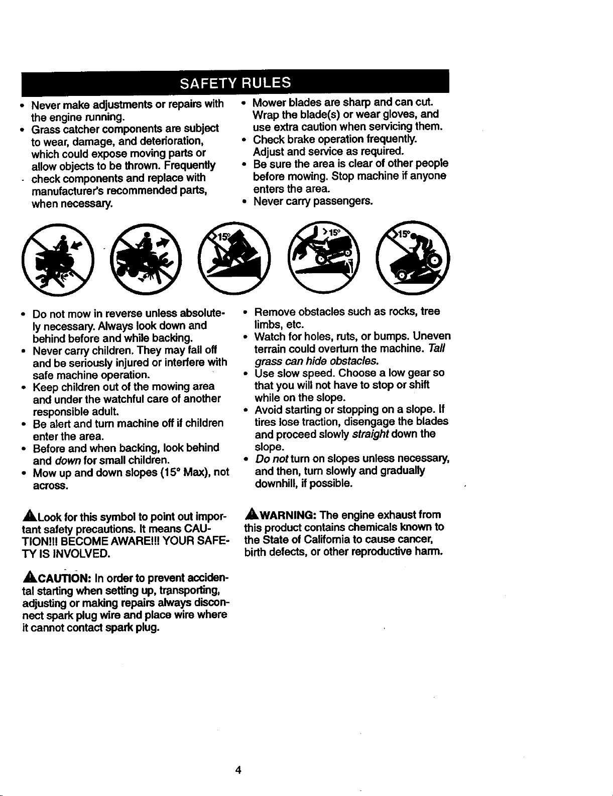
• Mow up and down slopes (15 ° Max), not
across.
_,Look for this symbol to point out impor-
tant safety precautions. It means CAU-
TION!!! BECOME AWARE!!! YOUR SAFE-
TY IS INVOLVED.
AcAuTION: In order to prevent acciden-
tal startingwhen setting up, tr-dnsporting,
adjusting or making repairs always discon-
nect spark plug wire and place wire where
itcannot contact spark plug.
• Remove obstacles such as rocks, tree
limbs, etc.
• Watch for holes, ruts, or bumps. Uneven
terrain could overtum the machine. Tall
grass can hide obstacles.
• Use slow speed. Choose a low gear so
that you will not have to stop or shift
while on the slope.
• Avoid starting or stopping on a slope. If
tires lose traction, disengage the blades
and proceed slowly straight down the
slope.
• Donottumonslopesunlessnecessary,
and then, tum slowly and gradually
downhill, if possible.
,_WARNING: The engine exhaust from
this product contains chemicals known to
the State of Califomia to cause cancer,
birth defects, or other reproductive harm.
4

PRODUCT SPECIFICATIONS
3ASOLINE :3.5GALLONS
3APACITY UNLEADED
_,ND TYPE: REGULAR
OIL TYPE SAE 10W-30
API-SF/SG/SH): (above 32°F)
SAE 5W-30
(below 32°F")
_ILCAPACITY: W/FILTER: 4,2 PINTS
W/O FILTER: 3.7 PINTS
SPARK PLUG: Champion RC12YC
GAP: .040")
GROUND SPEED FORWARD: 5.8
MPH): REVERSE: 2.1
TIRE PRESSURE: FRONT: 14 PSI
REAR: 10 PSI
CHARGING
SYSTEM: 15 AMPS@ 3600 RPM
BATTERY: AMP/HR: 35
MIN. CCA: 280
CASE SIZE: U1R
BLADE BOLT 27-35 FT. LBS.
TORQUE:
CONGRATULATIONS on your purchase
of a Craftsman Tractor. It has been
designed, engineered and manufactured
to give you the best possible dependability
and performance.
Should you experience any problem you
cannot easily remedy, please contact your
nearest Sears Authorized Service Center.
We have competent, well-trained techni-
cians and the proper tools to service or
repair this tractor.
Please read and retain this manual. The
instructions will enable you to assemble
and maintain your tractor properly. Always
observe the "SAFETY RULES".
MAINTENANCE AGREEMENT
A Sears Maintenance Agreement is avail-
able on this product. Contact your nearest
Sears store for details.
CUSTOMER RESPONSIBILITIES
• Read and observe the safety rules.
• Follow a regular schedule in maintain-
ing, caring for and using your tractor.
• Follow the instructions under =Mainte-
nance" and =Storage" sections of this
owner's manual.
,AWARNING: This tractor is equipped
with an internal combustion engine and
should not be used on or near any unim-
proved forest-covered, brush-covered or
grass-covered land unless the engine's
exhaust system is equipped with a spark
arrester meeting applicable local or state
laws (if any). If a spark arrester is used, it
should be maintained in effective working
order by the operator.
In the state of California the above is
required by law (Section 4442 of the
California Public Resources Code). Other
states may have similar laws. Federal
laws apply on federal lands. A spark
arrester for the muffler is available through
your nearest Sears Authorized Service
Center (See REPAIR PARTS section of
this manual).
5
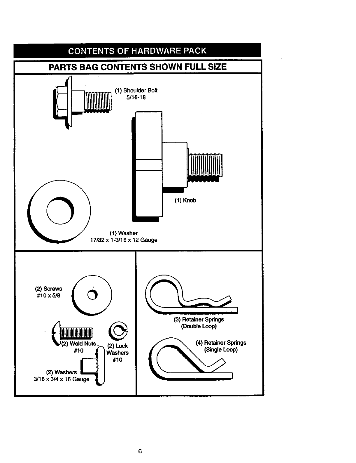
PARTS BAG CONTENTS SHOWN FULL SIZE
(1) Shoulder Bolt
1 5/16-18
I
(1) Knob
(1) Washer
17/32 x 1-3/16 x 12 Gauge
#10 x 5/8 t
(2) Screws
(2) Weld Nuts_ (2) Lock
#1_ Washers#10
(2) Washers
3/16 x 3/4 x 16 Gauge _w
(3) Retainer Spdngs
(Double Loop)
/I_"_ (4) Retainer Springs
(Single Loop)
6
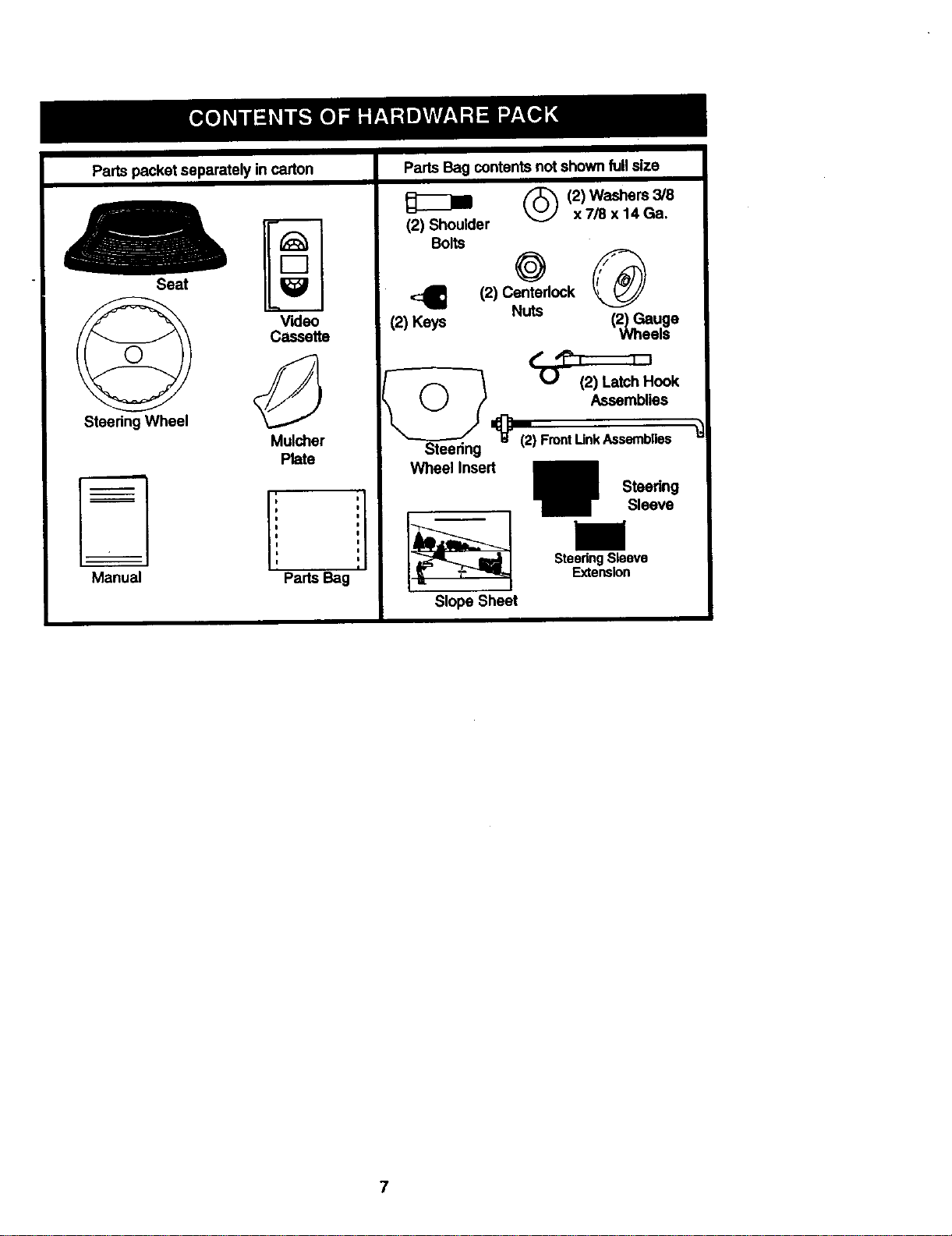
Partspacketseparatelyincarton
Parts Bag contents not shown full size
Seat
Video
Cassette
Steering Wheel
Mulcher
Plate
Manual Parts Bag
(2) Shoulder x7/8 x14 Ga.
Bolts
<:_ 12) Centerlock
(2) Keys Nuts
Steedng
Wheellnsed
Slope Sheet
(_(2) Washers 3/8
+®
(2) Gauge
U (2) Latch Hook
Assemblies
_(2) FrontLinkAssemblies
Steedng Sleeve
Extension
Wheels
Steedng
Sleeve
7

Yournewtractorhasbeenassembledatthefactorywithexceptionofthosepartsleft
unassembledforshippingpurposes.Toensuresafeandproperoperationofyourtractor
allpartsandhardwareyouassemblemustbetightenedsecurely.Usethecorrecttools
asnecessaryto insurepropertightness.Reviewthevideocassettebeforeyoubegin.
TOOLS REQUIRED FOR
ASSEMBLY
-Asocketwrenchsetwill makeassembly
easier. Standard wrench sizes you need
are listed below.
(1) 9/16" wrench (1) 3/4" Socket w/
(1) 112" wrench drive rachet
(1)Pliers (1) Phillips Screw-
(1) Utility knife driver
(1) Tire pressure gauge
_ Steedng
Wheel Insert
Hex Bolt
Lock Washer
Large Flat
Washer
When right or left hand is mentioned in
this manual, it means, from your point of
view, when you are in the operating posi-
tion (seated behind the steering wheel).
TO REMOVE TRACTOR FROM
CARTON
UNPACK CARTON
• Remove all accessible loose parts and
parts boxes from shipping carton (See
page 6).
• Cut, from top to bottom, along lines on
all four corners of shipping carton, and
lay panels flat.
• Remove mower and package materials.
• Check for any additional loose parts or
boxes and remove.
BEFORE ROLLING TRACTOR OFF
SKID
ATTACH STEERING WHEEL
• Remove hex bolt, lock washer and large
flat washer from steering shaft.
• Position front wheels of the tractor so
they are pointing straight forward.
• Slidethe steering sleeve over the steer-
in_]shaft.
• Align tabs and press steering sleeve
extension into bottom of steering wheel.
• Position steering wheel so cross bars
are horizontal (left to right) and slide
onto steering wheel adapter.
• Secure steering wheel to steering shaft
with hex bolt, lock washer and large flat
washer previously removed. Tighten
securely.
• Snap steering wheel insert into center
of steering wheel.
• Remove protective materials from trac-
tor hood and grill.
Steering
Wheel
IMPORTANT: Check for and remove any
staples in skid that may puncture tires
where tractor is to roll off skid.
TO ROLL TRACTOR OFF SKID (See
Operation section for location and
function of controls)
• Press lift lever plunger and raise attach-
ment lift lever to its highest position.
• Release parking brake by depressing
clutch/brake pedal.
• Place freewheel control in freewheeling
position to disengage transmission (See
"TO TRANSPORT" in the Operation
section of this manual).
• Roll tractor forward off skid.
Wheel
Adapter
8

HOW TO SET UP YOUR TRACTOR
CHECK BATTERY
• Lifthood to raised position.
• If this battery is put into service after
month and year indicated on label (label
located between terminals) charge bat-
tery for minimum of one hour at 6-10
amps. (See "BATTERY" in Maintenance
section of this manual for charging
instructions).
INSTALL SEAT
Adjust seat before tightening adjustment
knob.
• Remove cardboard packing on seat
pan.
• Place seat on seat pan and assemble
shoulder bolt. Tighten shoulder bolt
securely.
• Assemble adjustment knob and flat
washer loosely. Do not tighten.
• Lower seat into operating position and
sit on seat.
• Slide seat until a comfortable position is
reached which allows you to press
clutch/brake pedal all the way down.
• Get off seat without moving its adjusted
position.
• Raise seat and tighten adjustment knob
securely,
Seat
Seat Pan
CHECK TIRE PRESSURE
The tires onyour tractor were overinflated
at the factory for shipping purposes.
Correct tire pressure is important forbest
cuffing performance.
• Reduce tire pressure to PSI shown in
_PRODUCT SPECIFICATIONS" on
page 5 ofthis manual.
CHECK BRAKE SYSTEM
After you learn how to operate your trac-
tor, check to see that the brake is properly
adjusted. See =TOADJUST BRAKE" in
the Service and Adjustments section of
this manual.
INSTALL MOWER AND DRIVE BELT
Be sure tractor is on level surface and
mower suspension arms are raised with
attachment lift control. Engage parking
brake.
• Cut and remove ties securing anti-sway
bar and belts. Swing anti-sway bar to
left side of mower deck.
• Slide mower under tractor with dis-
charge guard to right side of tractor.
Shoulder
Bolt
Rat Washer
9

IMPORTANT:Checkbellfor properrout-
ingin allmowerpulleygrooves. Install
bellintoelectricclutchpulleygroove.
• Install one front link in top hole of the
right hand front mower bracket and right
hand front suspension bracket. Retain
with two single loop retainer springs as
shown.
• Install second front link in left hand
front suspension bracket only and
retain with single loop retainer spdng as
shown.
•Tum height adjustment knob counter-
clockwise until it stops.
• Lower mower linkage with attachment
lift control.
• Place the left hand suspension arm on
inward pointing deck pin. If necessary,
rock and raise front of mower to align
deck pin with the hole in suspension
arm. Retain with double loop retainer
spring with loops down as shown.
• Slide left side of mower back and install
the unattached front link in top hole of
the left hand front mower bracket.
Retain with single loop retainer spring
as shown.
• Place the right hand suspension arm on
inward pointing deck pin. If necessary,
rock and raise front of mower to align
deck pin with the hole in suspension
arm. Retain with double loop retainer
spring with loops down as shown.
• Connect anti-sway bar to chassis brack-
et under left footrest and retain with
double loop retainer spring.
• Turn height adjustment knob clockwise
to remove slack from mower suspen-
sion.
Raise mower to highest position.
Assemble gauge wheels (See "TO
ADJUST GAUGE WHEELS in the
Operation section of this manual).
CHECK MOWER LEVELNESS
For best cutting results, mower should be
properly leveled. See =TO LEVEL
MOWER HOUSING" in the Service and
Adjustments section of this manual.
CHECK FOR PROPER POSITION OF
ALL BELTS
See the figures that are shown for replac-
ing]motion, mower drive, and mower blade
drive belts in the Service and Adjustments
section of this manual. Verify that the
belts are routed correctly.
INSTALL MULCHER PLATE
• Install two latch hooks to mulcher plate
using screw, washer, lock washer, and
weld nut as shown.
Suspension
Arms Suspension
Chassis
Shoulder Bracket
•Boa
Gauge
Wheel
3/8 Washer 3/8-16
Center
Locknut
Use Pliersfor
Retainer Springs
Double Loop
• Retainer Spring
(Inward pointing
deck p_ns)
Double Loop
Retainer Sp.dng
Anti-Sway
Bar
Idler
Pulley
10
Front Mower
Retainer Springs
DLschargeGuard
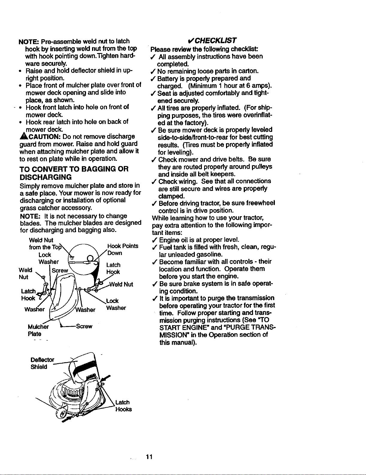
NOTE:Pre-assembleweldnuttolatch
hookbyinsertingweldnutfromthetop
withhookpointingdown.Tightenhard-
waresecurely.
• Raise and hold deflector shield in up-
right position.
• Place front of mulcher plate over front of
mower deck opening and slide into
place, as shown.
- • Hook front latch into hole on front of
mower deck.
• Hook rear latch into hole on back of
mower deck.
,_CAUTION: Do not remove discharge
guard from mower. Raise and hold guard
when attaching mulcher plate and allow it
to rest on plate while in operation.
TO CONVERT TO BAGGING OR
DISCHARGING
Simply remove mulcher plate and store in
a safe place. Your mower is now ready for
discharging or installation of optional
grass catcher accessory.
NOTE: It is not necessary to change
blades. The mulcher blades are designed
for discharging and bagging also.
Weld Nut
Lock
Washer
Weld
Nut
Latch
Mulcher '_,-----Screw
Plate
Hook Points
Latch
Lock
Washer
*/CHECKLIST
Please review the following checklist:
•/ All assembly instructions have been
completed.
,/No remaining loose parts in carton.
,/Battery is properly prepared and
charged. (Minimum 1 hour at 6 amps).
/ Seat is adjusted comfortably and tight-
ened securely.
/ All tires are properly inflated. (For ship-
ping purposes, the tires were overinflat-
ed at the factory).
,/Be sure mower deck is propedy leveled
side-to-side/front-to-rear for best cuffing
results. ('13res must be propedy inflated
for leveling).
•/ Check mower and drive belts. Be sure
they are routed propedy around pulleys
and inside all belt keepers.
,/Check wiring. See that all connections
are still secure and wires are propedy
clamped.
,/Before ddving tractor, be sure freewheel
control is in drive position.
While leaming how to use your tractor,
pay extra attention to the following impor-
tant items:
,/Engine oil is at proper level.
•/ Fuel tank is filled with fresh, clean, regu-
lar unleaded gasoline.
•( Become familiar with all controls - their
location and function. Operate them
before you start the engine.
•/ Be sure brake system is in safe operat-
ing condition.
,/It is important to purge the transmission
before operating your tractor for the first
time. Follow proper starting and trans-
mission purging instructions (See "TO
START ENGINE" and =PURGE TRANS-
MISSION" in the Operation section of
this manual).
Deflector
Shield
, 11
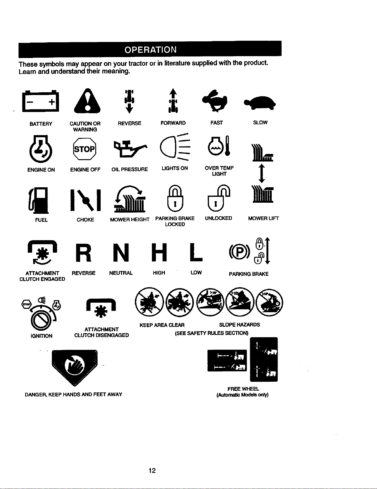
Thesesymbolsmayappearonyourtractororinliteraturesuppliedwiththe product.
Learnandunderstandtheirmeaning.
BATTERY CAUTIONOR REVERSE FORWARD FAST SLOW
WARNING
A
ENGINE ON ENGINE OFF OIL PRESSURE LIGHTS ON OVEL]RGTI_EMP T
FUEL CHOKE MOWER HEIGHT PARKING BRAKE UNLOCKED MOWER LIFT
ATTACHMENT REVERSE NEUTRAL HIGH LOW PARKING BRAKE
CLUTCH ENGAGED
ATTACHMENT
IGNITION CLUTCH DISENGAGED (SEE SAFETY RULES SECTION)
KEEP AREA CLEAR SLOPE HAZARDS
LOCKED
FREE WHEEL
DANGER, KEEP HANDS AND FEET AWAY
(AutomaticModelsonly)
12
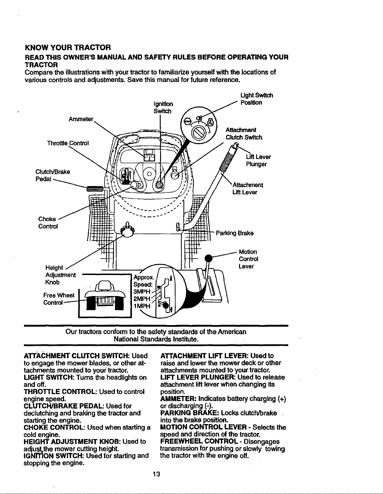
KNOW YOUR TRACTOR
READTHISOWNER'SMANUALANDSAFETYRULESBEFOREOPERATINGYOUR
TRACTOR
Comparethe illustrationswithyourtractortofamiliarizeyourselfwiththe locationsof
variouscontrolsand adjustments.Savethismanualfor future reference.
UghtSw h
Ignition
Switch
Throttle Control
Clutch/Brake
Peda
Chokq
Control
- Parking Brake
Position
Attechment
Clutch Switch
Uft Lever
Plunger
LiftLever
Height
Adjustment
Knob
Free Wheel
Our tractors conform to the safety standards of the Amedcan
National Standards Institute.
AI"I'ACHMENT CLUTCH SWITCH: Used
to engage the mower blades, or other at-
tachments mounted to youftractor.
LIGHT SWITCH: Turns the headlights on
and off.
THRO'I-rLE CONTROL: Used to control
engine speed.
CLUTCH/BRAKE PEDAL: Used for
declutching and braking the tractor and
starting the engine.
CHOKE CONTROL: used when starting a
cold engine.
HEIGHT ADJUSTMENT KNOB: Used to
adjust, the mower cutting height.
IGNITION SWITCH: Used for starting and
stopping the engine.
Motion
Control
Lever
ATTACHMENT LIFT LEVER: Used to
raise and lower the mower deck or other
attachments mounted to your tractor.
LIFT LEVER PLUNGER: Used to release
attachment lift lever when changing its
position.
AMMETER: Indicates battery charging (+)
or discharging (-).
PARKING BRAKE: Locks clutch/brake
into the brake position.
MOTION CONTROL LEVER - Selects the
speed and direction of the tractor.
FREEWHEEL CONTROL - Disengages
transmission for pushing or slowly towing
the tractor with the engine off.
13
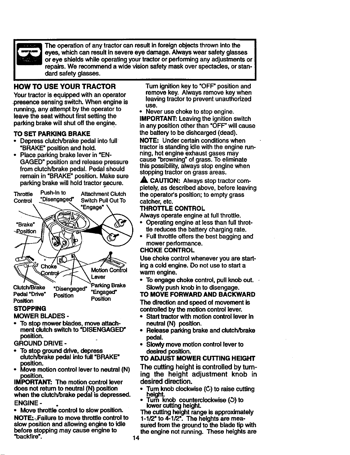
Theoperationofanytractorcanresultinforeignobjectsthrownintothe
eyes,whichcanresultinsevereeyedamage.Alwayswearsafetyglasses
oreyeshieldswhileoperatingyourtractoror performing any adjustments or
repairs. We recommend a wide vision safety mask over spectacles, or stan-
dard safety glasses.
HOW TO USE YOUR TRACTOR
Your tractor is equipped with an operator
.presence sensing switch. When engine is
running, any attempt by the operatorto
leave the seat without first settingthe
parkingbrake will shut offthe engine.
TO SET PARKING BRAKE
• Depress clutch/brake pedal intofull
=BRAKE" position and hold,
• Place parking brake lever in=EN-
GAGED" positionand release pressure
from clutch/brake pedal. Pedal should
remain in =BRAKE" position. Make sure
parkingbrake willholdtractor _.secure.
Throttle Push-In to AttachmentClutch
Control "Disengaged" Switch PullOut To
---__ Engage
Clutch/B"_ake -ni_=_=n=_r, "Parking Brake
Position Position
STOPPING
MOWER BLADES -
• To stop mower blades, move attach-
mont clutch switch to =DISENGAGED"
position.
GROUND DRIVE -
• To stop ground drive, depress,
clutchroreke pedal into full BRAKE"
position.
• Move motion control lever to neutral (N)
position.
IMPORTANT: The motion control lever
does not retum to neutral (N) position
when the clutch/brake pedal ksdepressed.
ENGINE -
• Move throttle'control to slow position.
NOT "P.:_.F-allure to move throttle control to
slow position and allowing engine to idle
before stopping may cause engine to
"backfire'.
Tum ignition key to "OFF" position and
remove key. Always remove key when
leaving tractor to prevent unauthodzed
use.
• Never use choke to stop engine.
IMPORTANT: Leaving the ignition switch
in any position other than =OFF" will cause
the battery to be dishcarged (dead).
NOTE: Under certain conditions when
tractor is standing idle with the engine run-
ning, hot engine exhaust gases may
cause "browning" of grass. To eliminate
this possibility, always stop engine when
stopping tractor on grass areas.
A CAUTION: Always stop tractor com-
pletely, as descdbed above, before leaving
the operator's position; to empty grass
catcher, etc.
THRO'n'LE CONTROL
Always operate engine at full throttle.
• Operating engine at less than full throt-
tle reduces the battery charging rate.
• Full throttle offers the best bagging and
mower performance.
CHOKE CONTROL
Use choke control whenever you are start-
ing a cold engine. Do not use to start a
warm engine.
• To engage choke control, pull knob out..
Slowly push knob in to disengage.
TO MOVE FORWARD AND BACKWARD
The direction and speed of movement is
controlled by the motion control lever.
• Start tractor with motion control lever in
neutral (N) position.
• Release parking brake and clutch_rake
pedal.
• Slowly move motion control lever to
desired position.
TO ADJUST MOWER CUTTING HEIGHT
The cutting height is controlled by turn-
ing the height adjustment knob in
desired direction.
•Tum knob clockwise (0) to raise cutting
• /urn Knoe counterclockwise (0)to
lower cutting height.
The cutting height range is approximately
1-1/2" to 4-1/2". The heights are mea-
sured from the ground to the blade tip with
the engine not running. These heights are
14

approximateandmayvarydepending
uponsoilconditions,heightof grassand
typesofgrassbeingmowed.
• The average lawn should be cut to
approximately 2-1/2 Inches during the
cool season and to over 3 inches during
hot months. For healthier and better
looking lawns, mow often and after
moderate growth.
• For best cutting performance, grass
over 6 inches in height should be
mowed twice. Make the first cut rela-
tively high; the second to desired height.
TO ADJUST GAUGE WHEELS
Gauge wheels are properly adjusted
when they are slightly off the ground when
mower is at the desired cutting height in
operating position. Gauge wheels then
keep the deck in proper position to help
prevent scalping in most terrain condi-
tions.
• Adjust gauge wheels with tractor on a
flat level surface.
• Adjust mower to desired cutting height
(See =TO ADJUST MOWER CUFFING
HEIGHT" in the Operation section of
this manual).
• With mower in desired height of cut po-
sition, gauge wheels should be assem-
bled so they are slightly off the ground.
Install gauge wheel in appropriate hole
with shoulder bolt, 3/8 washer, and 3/8-
16 Iocknut and tighten securely.
• Repeat for opposite side installing
gauge wheel in same adjustment hole.
,_CAUTION: Do not operate the mower
without either the entire grass catcher, on
mowers so equipped, or the discharge
guard in place.
TO OPERATE ON HILLS
_,CAUTION: Do not drive up or down
hillswith slopes greater than 15° and do
not drive acrossany slope; Use the slope
guide provided at the back ofthis manual
• Choose the slowest speed beTorestart-
ing up or down hills.
• Avoid stopping or changing speed on
hills.
control lever to slower possion.
If stoppingis absolutely necessary, push
clutch/brake pedal quicklyto brake posi-
i•lf slowingis necessary, move throttle
tion and engage parldng brake.
Move motioncontrol lever to neutral (N)
position.
IMPORTANT: The motion control lever
does not return to neutral (N) position
when the clutch/brake pedal is depressed.
parkingbrake and clutch/brake pedal.
Slowly move motton control lever to
i o restad movement, slowlyrelease
slowest setting.
Make all turns slowly.
Attachment Clutch
Switch Pull Out To
Attachment Lift Lever
High Position
/ Low
:-_'Position
// Discharge
7'\ Guard
Mounting
Bracket
3/8-16
Locknut Shoulder Bolt
3/8 Washer 'Gauge Wheel
TO OPERATE MOWER
Your tractor is equipped with an operator
presence sensingswitch. Any attempt by
the operator to leave the seat withthe
engine running and the attachment clutch
engaged will shut off the engine.
• Select desired height of cut.
• Lower mower with attachment liftcon-
troi.
• S_ mower blades by engaging attach-
mer_ crutchcontrol.
• TO STOP MOWER BLADES - disen-
gage attachment clutch control.
..... 15
1 -'- 4
Push In To _-_
"Disengage" "_) )_
TO TRANSPORT
When pushing or towing your tractor, be
sure to disengage transmission by placing
freewheel control in freewheeling posi-
tion. Freewheel control is located at the
rear drawhar of tractor.
• Raise attachment lift to highest position
with attachment lift control.
• Remove retainer spdng from freewheel
control rod.
• Push control rod in to disengage trans-
mission and reinsert retainer spdng into
control rod hole now on back side of the
bracket.
• Do not push or tow tractor at more than
two (2) MPHo . .
• To reengage transmission, reverse
above procedure;
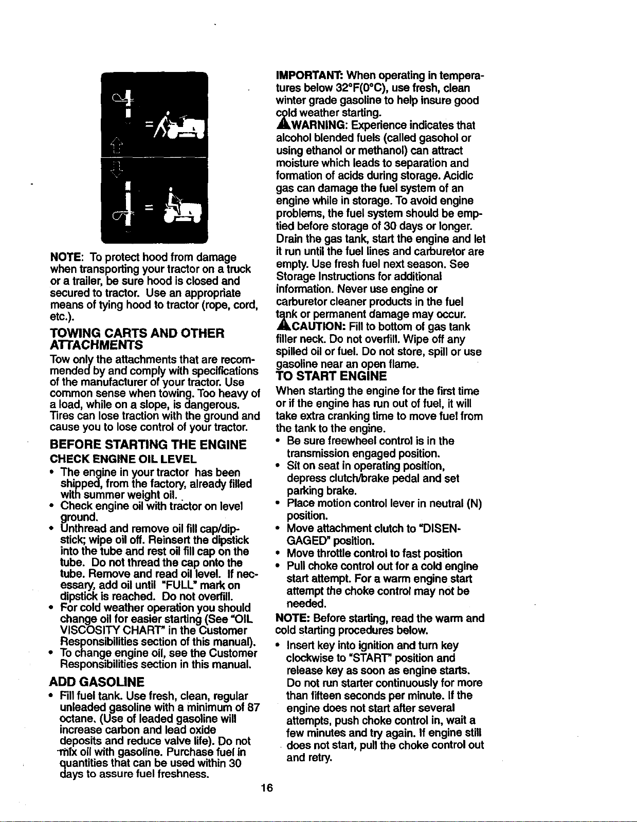
NOTE: To protect hood from damage
when transporting your tractor on a truck
or a trailer, be sure hood is closed and
secured to tractor. Use an appropriate
means of tying hood to tractor (rope, cord,
etc.).
TOWING CARTS AND OTHER
A'I-rACHMENTS
Tow only the attachments that are recom-
mendedby and comply with specifications
of the manufacturer of your tractor. Use
common sense when towing. Too heavy of
a load, while on a slope, is dangerous.
Tires can lose traction with the ground and
cause you to lose control of your tractor.
BEFORE STARTING THE ENGINE
CHECK ENGINE OIL LEVEL
shipped, from the factory, already filled
i The engine in your tractor has been
with summer weight oil.
Check engine oil with tractor on level
ground.
• Unthread and remove oil fill cap/dip
stick; wipe oil off. Reinsert the dipstick
into the tube and rest oil fill cap on the
tube. Do not thread the cap onto the
tube. Remove and read oil level. If nec-
essary, add oil until =FULL" mark on
dipstick is reached. Do not overfill.
• For cold weather operation you should
change oil for easier starting (See =OIL
VISCOSITY CHART" in the Customer
Responsibilities section of this manual).
• To change engine oil, see the Customer
Responsibilities section in this manual.
ADD GASOLINE
• Fill fuel tank. Use fresh, clean, regular
unleaded gasoline with a minimum of 87
octane, (Use of leaded gasoline will
increase carbon and lead oxide
deposits and reduce valve life). Do not
_Tx oil with gasoline. Purchase fuel in
quantities that can be used within 30
days to assure fuel freshness.
IMPORTANT: When operating in tempera-
tures below 32°F(0°C), use fresh, clean
winter grade gasoline to help insure good
_d weather starting.
WARNING: Experience indicates that
alcohol blended fuels (calledgasohol or
usingethanol or methanol) can attract
moisturewhich leads to separation and
formation of acids duringstorage. Acidic
gas can damage the fuel system of an
engine while in storage. To avoid engine
problems, the fuel system should be emp-
tied before storage of 30 days or longer.
Drain the gas tank, start the engine and let
it run until the fuel linesand carburetor are
empty. Use fresh fuel next season. See
Storage Instructionsfor additional
information. Never use engine or
carburetor cleaner productsin the fuel
_k or permanent damage may occur.
CAUTION: Fillto bottom of gas tank
filler neck. Do not overfill.Wipe off any
spilled oil or fuel. Do notstore, spill or use
gasoline near an open flame.
TO START ENGINE
When startingthe engine for the firsttime
or if the engine has run out of fuel, it will
take extra cranking time to move fuel from
the tank to the engine.
• Be sure freewheel controlis in the
transmissionengaged position.
• Sit on seat in operating position,
depress clutch/brake pedal and set
parkingbrake.
• Place motion control lever in neutral (N)
position.
• Move attachment clutchto =DISEN-
GAGED" position.
• Move throttle controlto fast position
• Pullchoke controlout for a cold engine
start attempt. For a warm engine start
attemptthe choke control may not be
needed.
NOTE: Before starting, read the warm and
cold starting procedures below.
• Insert key into ignition and tum key
clockwise to =START" position and
release key as soon as engine starts.
Do not run starter continuously for more
than fifteen seconds per minute. If the
engine does not start after several
attempts, push choke control in, wait a
few minutes and try again. If engine still
does not start, pull the choke control out
and retry.
16
WARM WEATHER STARTING (50 ° F
AND ABOVE)
• When engine starts, slowly push choke
control in until the engine begins to run
smoothly. If the engine starts to run
roughly, pull the choke control out slight-
ly for a few seconds and then continue
to push the control in slowly.
• The attachments and ground drive can
now be used. If the engine does not
accept the load, restart the engine and
allow it to warm up for one minute using
the choke as described above.
COLD WEATHER STARTING (50 ° FAND
BELOW)
• When engine starts, slowly push choke
control in until the engine begins to run
smoothly. Continue to push the choke
control in small steps allowing the
engine to accept small changes in
speed and load, until the choke control
is fully in. If the engine starts to run
roughly, pull the choke control out slight-
ly for a few seconds and then continue
to push the control in slowly. This may
require an engine warm-up period from
several seconds to several minutes,
depending on the temperature.
AUTOMATIC TRANSMISSION WARM-UP
• Before driving the unit in cold weather,
the transmission should be warmed up
as follows:
• Be sure the tractor is on level ground.
• Place the motion control lever in neu-
tral. Release the parking brake and
let the clutch/brake slowly return to
operating position.
• Allow one minute for transmission to
warm up. This can be done dudng the
engine warm up period.
• The-attachments can be used during
the engine warm-up period after the
transmission has been warmed up and
may require the choke control be pulled
out slightly.
NOTE: A high altitude (above 3000 feet)
or in cold temperatures (below 32 F) the
carburetor fuel mixture may need to be
adjusted for best engine performance.
See "TO ADJUST CARBURETOR" in the
Service and Adjustments section of this
manual.
,.==-.jr
PURGE TRANSMISSION
_,CAUTION: Never engage or disen-
gage freewheel lever while the engine is
running.
To ensure proper operation and perfor-
mance, it is recommended that the trans-
mission be purged before operating tractor
for the firsttime. This procedure will
remove any trapped air insidethe trans-
mission which may have developed during
shipping of your tractor.
IMPORTANT: Should your transmission
require removeal for service or replace-
ment, it should be purged after reinstalla-
tion before operating the tractor.
• Place tractor safely on level surface with
• engine off and parking brake set.
Disengage transmissionby placing free-
wheel controlin freewheeling position
(See =TOTRANSPORT" in this section
of manual).
• Sittinginthe tractor seat, start engine.
After the engine is running, movethrot-
tle controlto slow position.With motion
controllever in neutral (N) position,
slowly disengage clutch/brake pedal.
• Move motioncontrol lever to full forward
_,lositionand hold for five (5) seconds.
eve lever to full reverse position and
holdfor five (5) seconds. Repeat this
procedure three (3) times.
NOTE: During this procedure there will be
no movement of drive wheels. The air is
being removed from hydraulicdrive sys-
tem.
• Move motioncontrol lever to neutral (N)
position. Shut oftengine and set parking
brake.
• Engage transmission by placing free-
whee/control indriving position(See
=TOTRANSPORT" inthis section of
manual).
• Sitting in the tractor seat, start engine.
After the engine is running,move throt-
tle controlto half (1/2) speed. With
motioncontrollever in neutral (N)posi-
tion, slowly disengage clutch/brake
pedal.
• Slow_ move motioncontrol lever for-
ward, after the tractor moves approxi-
mately five (5) feet, slowly move motion
control lever to reverse position.After
the tractor moves approximately five (5)
feet returnthe motion controllever to
the neutral (N) position. Repeat this pro-
cedure with the motion controllever
three (3) times.
• Your tractor is now purged and now
ready for normal operation.
17
MOWING TIPS
• Tirechainscannotbeusedwhenthe
mowerhousingis attachedtotractor.
• Mower should be properly leveled for
best mowing performance. See "TO
LEVEL MOWER HOUSING" in the
Service and Adjustments section of this
manual.
-= The left hand side of mower should be
used for trimming.
• Ddve so that clippings are discharged
onto the area that has been cut. Have
the cut area to the right of the tractor.
This will result in a more even distribu-
tion of clippings and more uniform cut-
ting.
• When mowing large areas, start by turn-
ing to the right so that clippings will dis-
charge away from shrubs, fences, drive-
ways, etc. After one or two rounds, mow
in the opposite direction making left
hand turns until finished.
• If grass is extremely tall, it should be
mowed twice to reduce load and possi-
ble fire hazard from dried clippings.
Make first cut relatively high; the second
to the desired height.
• Do not mow grass when it is wet. Wet
grass will plug mower and leave unde-
sirable clumps. Allow grass to dry
before mowing.
• Always operate engine at full throttle
when mowing to assure better mowing
performance and proper discharge of
matedal. Regulate ground speed by se-
lecting a low enough gear to give the
mower the best cutting performance as
well as the quality of cut desired°
• When operating attachments, select a
ground speed that will suit the terrain
and give best performance of the at-
tachment being used.
MULCHING MOWING TIPS
IMPORTANT: For best performance, keep
mower housing free of built-up grass and
trash. Clean after each use.
• The special mulching blade will recut
the grass clippin_s many times and
reduce them in size so that as they fall
onto the lawn they will disperse into the
grass and not be noticed. Also, the
mulched grass will biodegrade quickly
to provide nutrients for the lawn. Always
mulch with your highest engine (blade)
speed as this will provide the best recut-
ting action of the blades.
• Avoid cuffing your lawn when it is wet.
Wet grass tends to form clumps and
interferes with the mulching action. The
best time to mow your lawn is the eady
aftemoon. At this time the grass has
dried and the newly cut area will not be
exposed to the direct sun.
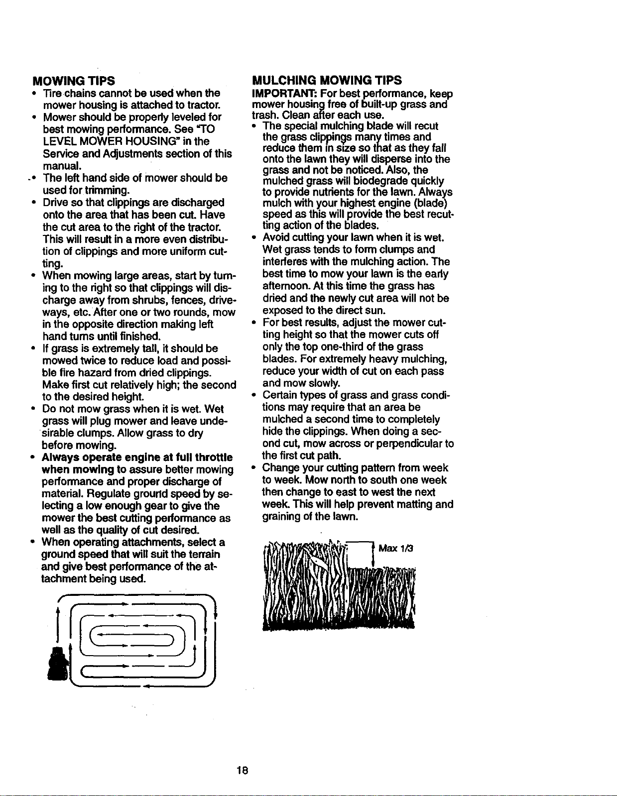
• For best results, adjust the mower cut-
ting height so that the mower cuts off
only the top one-third of the grass
blades. For extremely heavy mulching,
reduce your width of cut on each pass
and mow slowly.
• Certain types of grass and grass condi-
tions may require that an area be
mulched a second time to completely
hide the clippings. When doing a sec-
ond cut, mow across or perpendicular to
the first cut path.
• Change your cutting pattem from week
to week. Mow north to south one week
then change to east to west the next
week. This will help prevent matting and
graining of the lawn.
f
1
J
18

CUSTOMER RESPONSIBILITIES
.A,.T .A.CESC"EOUL
FILL iN DATES _e_'_'_. _'_r'_. o_ _,€_'_,d_"l_ .Yo,_
,eYou o.p E
REGULAR SERVICE aS- _p_,/ _-,r:/_,_ _.4_/,_
Check Brake Operation
Check Tira Pra_sure _ _
Check Operator Presence and
T Interlock Systems I_'
R CheckforLooseFasteners V' 1_7 ll/
T LubdcalionChart
0 Check BatteryLevel
CAS_n_,_.o., elad_ i"
R Cleon Battery and Terminels/Recharge t/#
Check Tronsaxle Cooling I_/
AdjustBlade Belt(s) Tension kl's
Adjust MolJonDrive BeER(s)Tension II_s
Check Engine Oil Level I_ I/'
_SERVICE DATES
ChangeE,_r_Oil _,_ V'
E CleanAir RERer t,_/_;
N Clean AirScreen
G Inspect Muffler/Spark Attester
Replace Oil RERef(If equipped) li_l.:
EN Clean Engine Cooling Fins
Replace Spark Plug I_
Replace Air Filter Paper Cartridge
Replace Fuel Filter ll_
I - Chenge mo_ o_en w4_moperatingunderi heavy loadof _'1highambienttemp. 5 - ff equippedw_hadjustabklsyslem.
2 - Servicen_ oilen whenopecatlngIn dittyor"dm4y¢_litkx_. 6 - NotI_lnKI | equipped'_'1 nl_lleniltce-lnle bldt_y.
3. # equippedwllhoi Ill.r, d_nge ol i_y 50 hour. 7 -"nlinten boer a_depb_ b_ to 35 ft..Ixk n_mm_.
4 - Rq_e blad_ mo_ o_en when mow_o in_ndy _i. Do r_ o_mghte_
GENERAL RECOMMENDATIONS LUBRICATION CHART
The warranty on this tractor does not cover eTie Rod BallJoints
items that have been subjected to operator eSpindle Zerk------I _ _eSpindle Zerk
abuse or negligence. To receive full value
from the warranty, operator must maintain eFront-------{-_ ._=,=,=,=,=,=,=,i__ eFmnt
t/
v',
i/
v',
I.'1
adjustments will need to be made periodi- Bearing __ Bearing
tractor as instructed in this manual. Some Wheel _ _ rw Wheel
cally to properly maintain your tractor. Zerk _-,,_ Zerk
All adjustments in the Service and eSteering-_' __ _ I "_"
Adjustments section of this manual should Sector | eEngine
be checked at least once each season.
• Once a year you should replace the
spark plug, clean or replace air filter, and
check blades and belts for wear. A new
spark plug and clean air filter assure
proper air-fuel mixture and help your
engine run better and last longer.
BEFORE EACH USE
• Check engine oil level.
Check brake operation.
Check operator presence and intedock which have special nylon bearings. Viscous lubd-
i Check tire pressure. IMPORTANT: Do not oil or grease the pivot points
systems for proper operation, cants will attract dust and dirt that will shorten the
C_-dck for loose fasteners, must be lubricated, use only a dry, powdered
Gear Teeth \
OSprey Silicone lubriant (Move Boots to Lubricats)
eGeneral Purpose Grease
@Refer toCustomer Responsibilities=ENGINE"
Section
life of the self-lubricating bearings. If you feel they
graphitetype lubricant sparingly.
19
-4 k--
%
:

TRACTOR
Always observe safety rules when per-
forming any maintenance.
BRAKE OPERATION
If tractor requires more than six (6) feet
stopping distance at high speed in highest
gear, then brake must be adjusted. (See
"TO ADJUST BRAKE" in the Service and
. Adjustments section of this manual).
TIRES
• Maintain proper air pressure inall tires
(See "PRODUCT SPECIFICATIONS"
on page 5 of this manual).
• Keep tires free ofgasoline, oil, or insect
control chemicals which can harm rub-
ber.
• Avoid stumps, stones, deep ruts, sharp
objects and other hazards that may
cause tire damage.
NOTE: To seal tire punctures and prevent
flat tires due to slow leaks, tire sealant
may be purchased from your local parts
dealer. Tire sealant also prevents tire dry
rotand corrosion.
OPERATOR PRESENCE SYSTEM
Be sure operator presence and interlock
systems are working properly. If your trac-
tordoes not function as described below,
repair the problem immediately.
• The engine should not start unless the
clutch/brake pedal is fully depressed
and attachment clutch control is in the
disengaged position.
• When the engine is running, any
attempt by the operator to leave the
seat without first setting the parking
brake should shut off the engine.
• When the engine is running and the
attachment clutch is engaged, any
attempt by the operator to leave the
seat should shut off the engine.
• The attachment clutch should never
operate unless the operator is in the
seat.
BLADE CARE
For best results mower blades must be
kept sharp. Replace bent or damaged
blades,
BLADE REMOVAL
• Raise mower to highest position to allow
access to blades.
• Remove hex belt, lockwasher and flat
washer secudhg blade.
• Install new or resharpened blade with
trailing edge up towards deck as shown.
IMPORTANT: To ensure proper assembly,
center hole in blade must align with star
on mandrel assembly.
• Reassemble hex bolt, lock washer and
flat washer in exact order as shown.
• Tighten boltsecurely (27-35 Ft. Lbs.
torque).
IMPORTANT: Blade bolt is Grade 8 heat
treated.
Trailing Edge Up Mandrel
Center Hok Assembly
Rat
Washer,
Star
*A Grade 8 heat treated bolt can be
identified by six lineson the bolt head.
TO SHARPEN BLADE
NOTE: We do not recommend sharpening
blade, but if you do, be sure the blade is
balanced.
Care should be taken to keep the blade
balanced. An unbalanced blade will cause
excessive vibration and eventual damage
to mower and engine.
• The blade can be sharpened with a file
or on a gdnding wheel. Do not attempt
to sharpen while it is on the mower.
• To check blade balance, you will need a
5/8" diameter steel bolt, pin, or a cone
balancer. (When using a cone balancer,
follow the instructions supplied with bal-
ancer).
• Slide blade onto an unthreaded portion
of the steel bolt or pin and hold the bolt
or pin parallel with the ground, if blade
is balanced, it should remain in a hod-
zontal position. If either end of the blade
moves downward, sharpen the heavy
end until the blade is balanced.
NOTE: Do not use a nail for balancing
blade. The lobes of the center hole may
Blade
5/8" Bolt or Pin
appear to be centered, but are not.
BA'n'ERY
Your tractor has a battery charging system
wh=ch is sufficient for normal use.
However, pedodic charging of the battery
with an automotive charger will extend its
life.
20
Keep battery bolts tight.
*Keep battery and terminals clean.
Keep small vent holes open.
Recharge at 6-10 amperes for 1 hour.
TO CLEAN BATrERYAND TERMINALS
Corrosion and dirt on the battery and ter-
minals can cause the battery to =leak"
power.
• Remove terminal guard.
• Disconnect BLACK battery cable first
then RED battery cable and remove
battery from tractor.
• Rinse the battery with plain water and
dry.
• Clean terminals and battery cable ends
with wire brush until bright.
• Coat terminals with grease or petroleum
jelly.
• Reinstall battery (See =REPLACING
BATTERY" in the SERVICE AND
ADJUSTMENTS section of this manu-
al).
V-BELTS
Check V-belts for deterioration and wear
after 100 hours of operation and replace if
necessary. The belts are not adjustable.
Replace belts if they begin to slip from
wear.
TRANSAXLE COOLING
The transmission fan and cooling fins
should be kept clean to assure proper
cooling.
Do not attempt to clean fan or transmis-
sion while engine is running or while the
transmission is hot.
• Inspect cooling fan to be sure fan
blades are intact and clean.
• Inspect cooling fins for dirt, grass clip-
pings and other materials. To prevent
damage to seals, do not use com-
pressed air or high pressure sprayer to
clean cooling fins.
TRANSAXLE PUMP FLUID
The transaxle was sealed at the factory
and fluid maintenance is not required for
the life of the transaxle. Should the
transaxle ever leak or require servicing,
contact your nearest authorized service
center/department.
ENGINE
LUBRICATION
Only use high quality detergent oil rated
with API service classification SF, SG, or
SH. Select the oil's SAE viscosity grade
according to your expected operating tam-
perature.
T[MFF.RA'PJRE RkW_ ANTICIPA_T_D8_ORE NEXT_t. C_kN_E
Change the oil after avery 50 hours of
operation or at least once a year if the
tractor is not used for 50 hours in one
year.
Check the crankcase oil level before start-
ing the engine and after each eight (8)
hours of operation. Tighten oil fill cap/dip-
stick securely each time you check the oil
level.
TO CHANGE ENGINE OIL
Determine temperature range expected
before oil change. All oil must meet API
service classification SF, SG, or SH.
• Be sure tractor is on level surface.
• Oil will drain more freely when warm.
• Catch oil in a suitable container.
• Remove oil fill cap/dipstick. Be careful
not to allow dirt to enter the engine
when changing oil.
• Remove drain plug.
• After oil has drained completely, replace
oil drain plug and tighten securely.
• Refill engine with oil through oil fill dip-
stick tube. Pour slowly• Do not overfill.
For approximate capacity see =PROD-
UCT SPECIFICATIONS" on page 5 of
this manual.
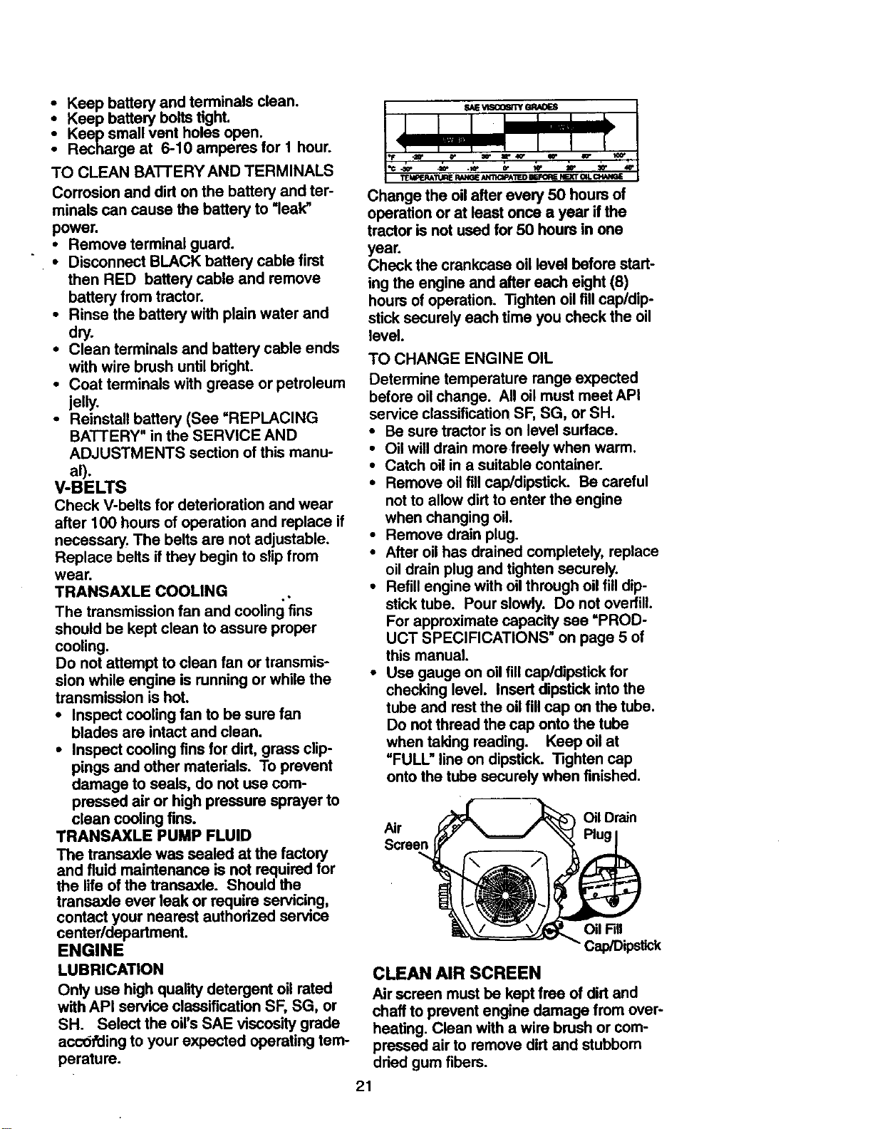
• Use gauge on oil fill cap/dipstick for
checking level. Insert dipstick into the
tube and rest the oil fill cap on the tube.
Do not thread the cap onto the tube
when taking reading. Keep oil at
=FULL" line on dipstick. Tighten cap
onto the tube securely when finished.
Air
Oil Drain
Screen
Oil Fill
Cap/Dipstick
CLEAN AIR SCREEN
Air screen must be kept free of dirt and
chaff to prevent engine damage from over-
heating. Clean with a wire brush or com-
pressed air to remove dirt and stubborn
dried gum fibers.
21
 Loading...