

Page 1

Owner's Manual
25.0 HP
ELECTRIC START
48" MOWER
AUTOMATIC
LAWN TRACTOR
Model No.
917.272261
• Safety
• Assembly
• Operation
• Maintenance
• Repair Parts
CAUTION:
Read and follow all
Safety Rules and Instructions
before operating this equip-
ment.
Sears, Roebuck and Co., Hoffman Estates, IL 60179
Visit our Craftsman website: www sears.corn/craftsman
For answers to your questions
about this product, Call:
1-800-659-5917
Sears Craftsman Help Line
5 am - 5 pm, Mon - Sat
Page 2
Warranty ............................................... 2
Safety Rules ......................................... 3
Product Specifications .......................... 6
Assembly .............................................. 8
Operation ............................................ 12
Maintenance Schedule ...................... 18
LIMITED'FWOYEAR WARRANTY ON CRAFTSMAN RIDING EQUIPMENT PARTS
For two (2) years from the date of purchase, if this Craftsman Riding Equipment is
maintained, lubricated and tuned up according to the instructions in the owner's
manual, Sears will repair or replace, free of charge, any parts found to be defective in
material or workmanship. Warranty service is available free of charge by returning
your Craftsman riding equipment to your nearest Sears Service Center. In-home
warranty service is available but a trip charge will apply. This warranty applies only
while this product is in the United States.
This Warranty does not cover:
• Expendable items which become worn during normal use, such as blades, spark
plugs, air cleaners, belts and oilfilters.
• Tire replacement or repair caused by punctures from outside objects, such as nails,
thorns, stumps,or glass.
• Repairs necessary because of operator abuse, including but not limited to, damage
caused by towing objects beyond the capability of the riding equipment, impacting
objects that bend the frame or crankshaft, or over speeding the engine.
• Repairs necessary because of operator negligence, includingbut not limited to,
electrical and mechanical damage caused by improper storage, failure to use the
proper grade and amount of engine oil, failure to keep the deck clear of flammable
debris, or the failure to maintain the equipment according to the instructions
contained in the owner's manual.
• Engine (fuel system) cleaning or repairs caused by fuel determined to be contami-
nated or oxidized (stale). In general, fuel should be used within thirty (30) days of its
purchase date.
• Riding equipment used for commercial or rental purposes. A productis =used for
commercial purpose" if is used for any purpose otherthan single family household
dwellings or in usage where profitis made.
Maintenance ....................................... 18
Service and Adjustments .................... 23
Storage ............................................... 29
Troubleshooting ................................. 30
Repair Parts ........................................ 34
Parts Ordering ..................... Back Cover
LIMITED 90 DAY WARRANTY ON BA]-(-ERY
For ninety (90) days from date of purchase, it any battery included with this riding
equipment proves defective in material or workmanship and our testing determines
the battery will not hold a charge, Sears will replace the battery at no charge. War-
ranty service is available free of charge by returning your Craftsman riding equipment
to your nearest Sears Service Center. In-home warranty service isavailable but a trip
charge will apply. This warranty applies onlywhile this product is in the United States.
TO LOCATETHE NEAREST SEARS SERVICE CENTER ORTO SCHEDULE IN-
HOME WARRANTY SERVICE, SIMPLY CONTACT SEARS AT 1-800-4-MY-HOME
This Warranty gives you specific legal dghts, and you may also have other dghts
which may vary from state to state.
Sears, Roebuck and Co., [:)/817WA, Hoffman Estates, IL 60179
Page 3
IMPORTANT:This cutting machine s capable of amputatinghands and feet and
throwing objects. Failure to observe the followingsafety instructionscould result in
seriousinjury or death.
I.GENERAL OPERATION I1.SLOPE OPERATION
• Read, understand,and follow all
instructionsin the manual and on the
machine before starting.
• Only allow responsibleadults,who are
famiUar with theinstructions, tooperate
the machine.
• Clear the area of objects such as rocks,
toys,wire, etc., which couldbe picked
up and thrownby the blade.
• Be sure the area is clear of other people
before mowing. Stop machine if anyone
enters the area.
• Never carry passengers.
• Do not mowin reverse Lmlessabsolutely
necessary. Always look down and
behind before and while backing.
• Be aware ofthe mower discharge
directionand do not point it at anyone.
Do not operatethe mower without either
the entire grass catcheror the guard in
place.
• Slow down before taming.
• Never leave a rUr_ing machine
unattended. Alwaysrumoff blades, set
parkingbrake, stop engine, and remove
keys before dismounting.
Turn off blades when not mowing.
Stop engine before removing grass
catcher or uncloggingchute.
Mow orgyin daylight or good artificial
light.
Do not operate the machine whileunder
the influenceof alcoholor drugs.
Watch fortrafficwhen operatingnear or
crossing roadways.
Use extra care when loading or unload-
ingthe machineinto a trailer ortrack.
Data indic_tasthat operators, age 60
years and above, are invelved in a large
percentage of ridingmower-related
iojurles.These operatorsshould
evaluate their abilityto operate the riding
mower safely enoughto protectthem-
selves and othersfrom seriousInjury.
• Keep machine free ofgrass, leaves or
other debrisbuild-upwhich can touch
hotexhaust / engine parts and bum. Do
notallew the mower deck to plowleaves
or other debris whichcan cause build-
up to eecL_.Clean any oilor fuel
spillage before operatingor storing the
machine. Allow machineto coal before
storage.
Slopes are ama or factor related to loss-of-
control and tpover accidents,whichcan re-
ealt in severe injury or death. All slopes
require extra caution. Ifyou cannot pack up
the slope or if you feel uneasy on it, do not
mow it.
DO:
• Mow up and down slopes, not across.
• Remove obstacles such as rocks,tree
limbs, etC.
Watch for holes, ruts, or bumps. Uneven
terrain could overturnthe machine. Tall
grass can hide obstacles.
Use slaw speed. Cheese a low gear so
that you willnot have to stop orshift
while on the slope.
Followthe manufacturer'srecommenda-
tions for wheel weights or counter-
weightsto improve stablely.
Use extra care with grass catchers or
othor attachments. These can change
the stabilityofthe machine.
Keep all movement on the slopes slow
and gradual. Do not make sudden
changes in speed or direction,
Avoid starting or stopping on • slope, ti
tires lose traction, disengage the blades
and proceed siov_y straight down _e
slope.
DO NOT:
• Do not turnan slopes unless necessary,
and tben, turn slowly and gradually
downhill, if possible.
• Do notmow near drop-offs, ditches,or
embankments. The mower could
suddenlyturnover if a wheel is overthe
edge of a cliffor ditch, or if anedge
caves in.
• DOnot mow on wet grass. Reduced
traction could cause sliding.
• Do not tryto stabilize the machine by
puttingyourfoot an the ground.
• Do notuse grasscatcher an steep
slopes.
Page 4
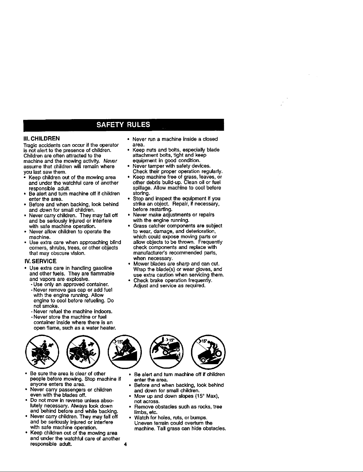
III. CHILDREN
Tragic accidents can occur if the operator
is not alert to the presence of children.
Childrenare often attracted to the
machine and the mowing activity. Never
assume that childrenwilt remain where
you last saw them.
• Keep children out of the mowing area
and under the watchful care of another
responsible adult.
• Bealert and turn machine off ff children
enter the area.
• Before and when backing, look behind
and down for small children.
• Nevercarry children. They may fall off
and be seriously injured or _nterfere
with safe machine operation.
• Never allow children to operate the
machine,
• Use extra care when approaching blind
comers, shrubs, trees, or other objects
that may obscure vision.
IV. SERVICE
• Use extra care in handling gasoline
and otberfuels. They are flammable
and vapors are explosive.
-Use only an approved container.
-Never remove gas cap oradd fuel
with the engine running. Allow
engine to cool before refueling. Do
notsmoke,
- Never refuel the machine Indoors.
-Never store the machine or fuel
container inside where there is an
open flame, such as a water heater.
• Never run a machine inside a closed
area.
• Keep nuts and bolts, especially blade
attachment bolts, tight and keep
equipment in good condition.
• Never tamper with safety devices,
Check their proper operation regularly.
• Keep machine free of grass, leaves, or
other debds build-up. Glean oil or fuel
spillage. Allow machine to cool before
stodng.
• Stop and inspectthe equipment ifyou
strike an object. Repair, ifnecessary,
before restarting.
• Never make adjustments or repairs
with the engine running.
• Grass catcher components are subject
to wear, damage, and deterioration,
which could expose moving parts or
allow objects to be thrown. Frequently
check components and replace with
manufacturer's recommended parts,
when necessary.
• Mower blades are sharp and can cut.
Wrap the blade(s) or wear gloves, and
use extra caution when servicingthem,
• Check brake operation frequently.
Adjust and service as required.
• Besure the area is clear of other
people before mowing. Stop machine if
anyone enters the area,
• Never carry passengers or children
even with the blades off.
• Do not mow inreverse unlessabso-
lutely necessary. Always look down
and behind before and while backing.
• Never carry children. They mayfall off
and be seriously injured or interfere
with safe machine operation.
• Keep children out of the mowing area
and underthe watchful care of another
responsible adult.
0 Be alert and turn machine offIf children
enter the area.
• Before and when backing, look behind
and down for small children.
• Mow Upand down slopes (15 ° Max),
not across.
• Remove obstacles suchas rocks,tree
limbs, etc.
• Watch for holes, ruts, or bumps.
Uneven terrain could overturn the
machine. Tall grass can hide obstacles.
Page 5
• Use slow speed. Choose a low gear so
that you will not have to stop or shift
while on the slope.
• Avoid starting or stopping on a slope. If
tires lose traction, disengage the
blades and proceed slowly straight
down the slope.
• If machine stops while going uphill,
disengage blades, shift into reverse
and back down slowly.
• Do not turn on slopes unless neces-
sary, and then, turn slowly and gradu*
ally downhill, if possible.
_Look for this symbol to pointout
importantsafety precautions.It means
CAUTIONlif BECOME ALERTI!! YOUR
SAFETY IS INVOLVED.
_I, CAUTION: In order to prevent
accidental starting when setting up,
transporting, adjusting or making repairs,
always disconnect spark plug wire and
place wire where if cannot contact spark
plug.
_,CAUTION: Do not coast down a hill in
neutral, you may lose control of the
tractor.
_IbCAUTION: Tow only the attachments
that are recommendedby and comply
with specifications of the manufacturer of
your tractor. Use common sense when
towing. Operate onlyat the lowest
possiblespeed when on a slope. Too
heavy of a load, while on a slope, is
dangerous. Tires can lose traction with
the ground and cause you to lose control
of your tractor.
,_WARNING: Engine exhaust, some of
its constituents, and certainvehicle
components contain or emit chemicals
known to the State of Californiato cause
cancer and birth defects or other repro-
ductive harm.
_WARNING: Battery posts,terminals
and related accessories contain lead and
lead compounds, chemicals known to the
State of California to cause cancer and
birthdefects or other reproductive harm.
Wash hands after handling.
Page 6
PRODUCTSPECIFICATIONS
GASOLINE 3.5GALLONS
CAPACITY UNLEADED
ANDTYPE: REGULAR
OILTYPE SAE30
(ABOVE32°F)
API-SF-SJ): SAE5W-30
(BELOW32°F)
OILCAPACITY:W/FILTER:4.0PINTS
W/OFILTER:3.75PINTS
SPARKPLUG:CHAMPIONRC12YC
(GAP:.040")
GROUNDSPEEDFORWARD:0-5.5
',MPH): REVERSE: 0-2.4
FIREPRESSURE: FRONT: 14 PSI
REAR: 10PSI
_HARGING
SYSTEM: 16 AMPS @3600 RPM
3ATIE RY: AMP/HR: 30
MIN. CCA: 240
CASE SIZE: U1R
BLADE BOLT 45-55 FT. LBS,
rORQUE:
CONGRATULATIONS on your purchase
ofa newtractor. It has been designed,
engineered and manufactured to give you
the best possible dependability and
performance.
Should you experience any problem you
cannot easily remedy, please contact a
Sears or other qualified service center.
We have competent, wall-trained techni-
cians and the proper tools to service or
repairthis tractor.
Please readand retain this manual. The
instructionswill enable you to assemble
and maintain your tractor properly.
Always observe the "SAFETY RULES".
REPAIR AGREEMENT
A Repair Agreement is available on this
product. Contact your nearest Sears
storefor details.
CUSTOMER RESPONSIBILITIES
• Read and observe the safety rules.
• Follow a regular schedule in maintain-
ing, caring for and using your tractor.
• Follow the instructionsunder "Mainte-
nance" and "Storage" sections of this
owner's manual.
• I,WARNING: This tractoris equipped
with an internal combustion engine and
should not be used on or near any
unimproved forest-covered, brush-
covered or grass-covered land unless the
engine's exhaust system is equipped with
a spark arrester meeting applicable local
or state laws (ifany). If a sparkarrester is
used, it should be maintained in effective
working order bythe operator.
In the state of Californiathe above is
required by law (Section 4442 of the
California Public Resources Code).
Other states may have similar laws.
Federal laws apply on federal lands. A
spark arrester for the muffler isavailable
through yournearest Sears service
center (See REPAIR PARTS sectionof
this manual).
Page 7
Steering
Wheel Insert Steering Sleeve
(1) W_
17/32 x 1-3/16 x 12 Gauge
Retainer Springs
)
Steering Wheel
_(1) Knob
Mower
(2)Flanged
(2) Retainer Springs (single loop)
• (4) Adjusting Bar Gauge Wheels i-O
i ,_ _ (4)Retainer Springs L_ JI
_e _ _ __(doubla loop) (4) Clevis Pins w
_.1 f T// 3/8-16 • [ • J _
,-_ 'k,__._/(4 (4) Washers _&=kJJ (4) Shoulder Bolt
-- -- Nose Roller _']
-- -- -- _'0_ Nose Roller
(4) Whee s
3/8 x 3/4 x 14 Ga.'_"
(l)FrontPlate _"
Assembly _%
)) i
=.oo"°s°Ro,,e .-IIIIIIIlllllll!l!llllllll]<=,.oxBolts B Brackets
( ) knuts _ R/IR 1R _t t _(2) Washers_._.._
5116-18 ..... "..... 17/32 x 7/8 x 16 GaW
Video CasseUa Keys Slope Sheet
[1
(2) Keys
For Future Use
7
Page 8
Your new tractor has been assembled at the factory with exception of those parts left
unassembled for shipping purposes• To ensure safe and proper operation of your
tractor all parts and hardware you assemble must be tightened securely. Use the
correct tools as necessary to insure proper tightness, Review the video cassette before
you begin.
TOOLS REQUIRED FOR ASSEMBLY
A socket wrench set will make assembly
easier. Standard wrench sizes you need
are listed below.
(1) 9/16" wrench (t) 3/4" Socket w/
(1) 1/2" wrench drive ratchet
(1) Utility knife (1) Pliers
(1) Tire pressure gauge
When right or left hand is mentioned in
this manual, it means, from your pointof
view, when you are in the operating
position (seated behind the steering
wheel).
TO REMOVETRACTOR FROM
CARTON
UNPACK CARTON
1. Remove all accessible loose parts
and partscartons from carton.
2. Cut, from top to bottom, along lines on
all four comers of carton, and lay
panels flat.
3. Remove mower and packing materi-
als.
4. Check for any additional loose parts
or cartons and remove.
BEFORE REMOVINGTRACTOR
FROM SKID
ATTACH STEERING WHEEL
1. Remove hax nut and largeflat washer
from steering shaft.
2. Positionfront wheels of the tractor so
they are pointing straight forward.
3. Slide the steadng sleeve over the
steering shaft.
4. Positionsteedng wheel so cross bars
are horizontal (left to dght) and slide
onto steering wheel adapter.
5. Secure steering wheel to steedng
shaft with hex nutand largeflat
washer previously removed. Tighten
securely.
6. Snap steering wheel insert intocenter
of steedng wheel.
7. Remove protective materials from
tractor hood and gdll.
IMPORTANT: Check for and remove any
staples in skid that may puneturetires
where tractor is to roll off skid.
I/F_'_\I t_=.,€,T WheelInsert
II
I_ I_ge Flat Washer
Steedng /_J _,)
SteeringWheel
Adapter_ v
$,eerio, :
S eeve_, ,,'t:J._ ., .') ,"
HOWTO SET UPYOURTRACTOR
CHECK BA'I-rERY
1. Lifthood to raised position.
NOTE: Ifthis batteryis putintoservice
after month and year indicated on label
(label located between terminals) charge
battery for minimum of one hour at 6-10
amps. (See "BATTERY"in Maintenance
section ofthis manual for charging
instructions).
.,........f _ Lab_
INSTALL SEAT
Adjust seat before tightening adjustment
knob.
1. Remove adjustment knob and flat
washer secudng seat to cardboard
packing and set aside for assembly of
seat to tractor.
2. Pivotseat upward and remove from
the cardboard packing. Remove the
cardboard packing and discard.
3. Place seat on seat pan so head of
shoulder bolt is positionedover large
8 slotted hole in pan.
_ s I _J III
Page 9
4. Pushdownonseattoengage
shoulderboltinslotandpullseat
towardsrearoftractor.
5. Pivot seat and pan forward and
assemble adjustment knob and flat
washer loosely. Do not tighten.
6. Lower seat into operating position and
sit in seat.
7. Slide seat until a comfodable position
is reached which allows you to press
clutch/brake pedal all the way down.
8. Get off seat without moving its
adjusted position.
8. Raise seat and tighten adjustment
knob securely.
NOTE: You may now roll or ddve your
tractor off the skid. Follow the appropdate
instructionbelow to remove the tractor
from the skid.
TO ROLLTRACTOR OFF SKID (See
Operation section for location and
function of controls)
1. Press lift lever plunger er,d raise
attachment liftlever to itshighest
position.
2. Release parklt_:3brake by depressing
brake pedal.
8. Place freewheel control in freewheel-
ing position to disengage transmis-
sion (See "TO TRANSPORT" in the
Operation section of this manual).
4. Roll tractorforward oft skid.
TO DRIVETRACTOR OFF SKID (See
Operation section for location and
function of controls)
_l, WARNING: Before starting,read,
understand and follow all instructionsin
the Operation sectionof this manual. Be
sure tractor is in a well-ventilated area. Be
sure the area in front of tractor isclear of
other people and objects.
Seat
Shoulder
Bolt
1. Be sure all the above assembly steps
have been completed.
2. Check engine oll level and fill fuel
tank with gasoline.
3. Place freewheel control In "transmis-
sion engaged" position.
4. Sit on seat in operating position,
depress brake pedal and set the
parking brake.
5. Press lif'_lever pfunger and raise
atlachment lift lever to its highest
position.
6. Start the engine. After engine has
started, move throttle controlto idle
position.
7. Release parking brake.
8. Slowly depress forward ddve pedal
and ddve tractoroff skid.
9. Apply brake to stoptractor and set
parking brake.
10.Turn ignitionkey to "OFF" position.
Continue with the instructions that follow.
ASSEMBLE GAUGEWHEELSTO
MOWER DECK
The gauge wheels are designed to keep
the mower deck in proper position when
operatingmower. Be sure they are
propedy adjured to ensure oplimam
mower performance.
1. Slide gauge wheel bar down into
bracket channel, Be sure that gauge
wheel bar aligning holes are on top.
Assemble gauge wheels as shown
using shoulder bolts, 3/8 washers and
3/8-16 center lecknuts and tighten
securely.
2. Far ease of mower to tractor assem-
bly, raise gauge wheels to highest
position and retain with clevis pins
and spdng retainers.
NOTE: Adjust gauge wheels before
operating mower, See "TO ADJUST
GAUGE WHEELS" in the Operation
section of this manual.
Shoulder
Bolt Bar--_] ._.
Wheal'_ I 13/8-t6Center
3/8 Washerj v L_ Locknut
Page 10
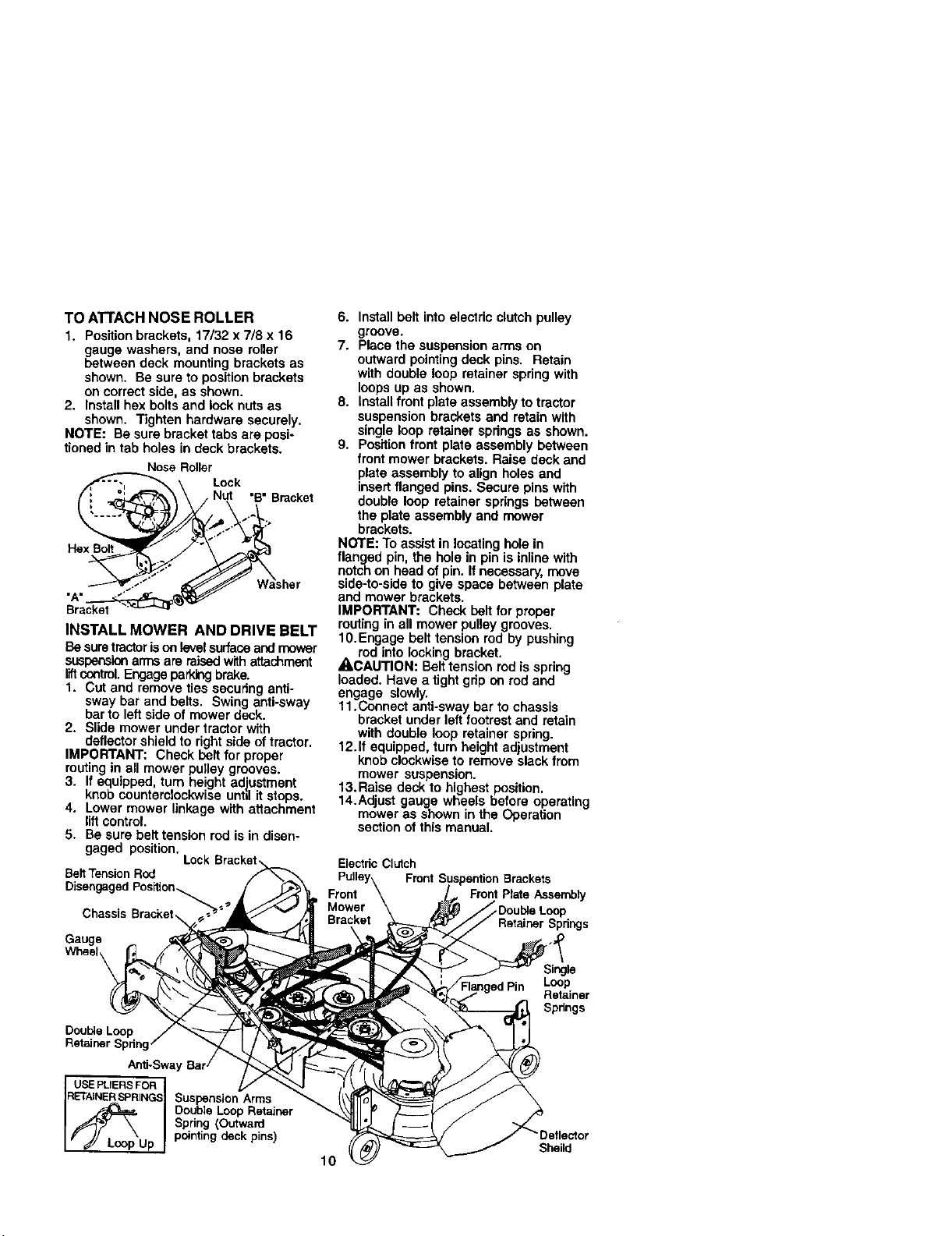
TO ATTACH NOSE ROLLER
1. Pos_ion brackets, 17132x 7/8 x 16
gauge washers, and nose roller
between deck mounting brackets as
shown. Be sure to positionbrackets
on correct side, as shown.
2. Install hex bolts and lock nuts as
shown. Tighten hardware securely.
NOTE: Be sure bracket tabs are posi-
tioned in tab holes in deck brackets.
Nose Roller
Lock
"B" Bracket
"A"
Bracket
INSTALL MOWER AND DRIVE BELT
Be suretractorison levelsurfaceand mower
suspensionarmsare _sed withattachment
codtmi. Engage parkingbrake.
1. Cut and remove ties securing anti-
sway bar and belts, Swing anti-sway
bar to left side of mower deck.
2. Slide mower under tractor with
deflectorshield to right side of tractor.
IMPORTANT: Check belt for proper
routing in all mower pulley grooves.
3. If equipped, turn height adiustment
knob counterclockwise unhl it stops.
4. Lower mower linkage with attachment
lift control.
5. Be sure belttension rod is in disen-
gaged position.
BeltTension Rod
Chassis Brackel,
Gauge
6. Installbelt into electric clutch pulley
groove.
7. Place the suspension arms on
outward pointingdeck pins. Retain
with double loop retainer springwith
loops up as shown.
8. Install front plate assembly to tractor
suspensionbrackets and retain with
single loop retainer springs as shown.
9. Positionfront plate assembly between
front mower brackets. Raise deck and
plate assembly to align holes end
insert flanged pins. Secure pins with
double loop retainer springs between
the plate assembly and mower
brackets.
NOTE: Toassist in locating hole in
flanged pin, the hole in pin is inline with
notch on head of pin. If necessary, move
side-to-side to give space between plate
and mower brackets.
IMPORTANT: Check belt for proper
routingin all mower pulley grooves.
10.Engage belttension rod by pushing
rod into locking bracket.
ACAUTION: Belt tension rodis spring
loaded. Have a tight grip on rod and
engage slowly.
11.Connect anti-sway bar to chassis
bracket under left footrest and retain
with double loop retainer spring.
12.If equipped, turn height adjustment
knob clockwiseto remove slack from
mower suspension.
13.Raise deck to highest position.
14.Adjust gauge wheels before operating
mower as shown in the Operation
section of this manual.
Electric Clutch
Pulley\ Front Suspention Brackets
Front Front Plate/_ssernbly
Mower \ _Double Loop
Bracket Relainer Springs
Single
Loop
Retainer
Spnngs
Double Loop
Retainer Spring
Anti-Sway
RETAINERSPRINGS Suspension Arms
I_L_p Double Loop Retainer
USEPLIERSFOR I
Spring (Outward
Up pointing deck pins)
Sheild
10
Page 11
CHECKTIRE PRESSURE
The tires on your tractorwere overinltated
at the factory for shipping purposes.
Correct tire pressure is important for best
cutting performance.
• Reduce tire pressure to PSI shown in
"PRODUCT SPECIFICATIONS" section
ofthis manual.
CHECK DECK LEVELNESS
For best cuttingresults, mower housing
should be properlyleveled. See "TO
LEVEL MOWER HOUSING" inthe
Service and Adjustments section of this
manual.
CHECK FOR PROPER POSITION OF
ALL BELTS
See the figures that are shown for
replacing motion and mower blade drive
belts in the Service and Adjustments
section ofthis manual. Verifythat the
belts are routed correctly.
CHECK BRAKE SYSTEM
After you learn how to operate your
tractor,check to see that the brake is
pmpedy adjusted. See "TO ADJUST
BRAKE" in the Service and Adjustments
section of this manual.
_CHECKLIST
BEFOREYOU OPERATE AND ENJOY
YOUR NEW TRACTOR, WE WISH TO
ASSURETHATYOU RECEIVETHE BEST
PERFORMANCE AND SATISFACTION
FROM THIS QUALITY PRODUCT.
PLEASE REVIEWTHE FOLLOWING
CHECKLIST:
/ All assembly instructionshave been
completed.
J No remaining loose parts in carton.
4" Battery is propedy prepared and
charged. (Minimum 1 hour at 6 amps).
J" Seat is adjusted comfortably and
tightened securely.
JAil tires are properly inflated. (For
shipping purposes, the tires were
overinflated at the factory).
J" Be sure mower deck is properly leveled
side-to-side/front-to-rear for best cutting
results. (Tires must be properly inflated
for leveling).
/ Check mower and drive belts. Be sure
they are routed properly around pulleys
and inside all belt keepers.
/ Check wiring. See that all connections
are still secure and wires are properly
clamped.
/ Before driving tractor, be sure free-
wheel controlis in drive position.
WHILE LEARNING HOWTO USEYOUR
TRACTOR, PAYEXTRA A'I-FENTION TO
THE FOLLOWING IMPORTANT ITEMS:
J" Engine oil is at proper level.
/ Fuel tank is filled with fresh, clean,
regular unleaded gasoline.
J"Become familiarwith all controls - their
locationand function. Operate them
before you start the engine.
,/Be sure brake system isin safe
operating condition.
,/It is importantto purge the transmission
beforeoperating your tractor forthe first
time. Followproper startingand
transmission purging instructions (See
"TO START ENGINE" and "PURGE
TRANSMISSION" in the Operation
section of this manual).
11
Page 12
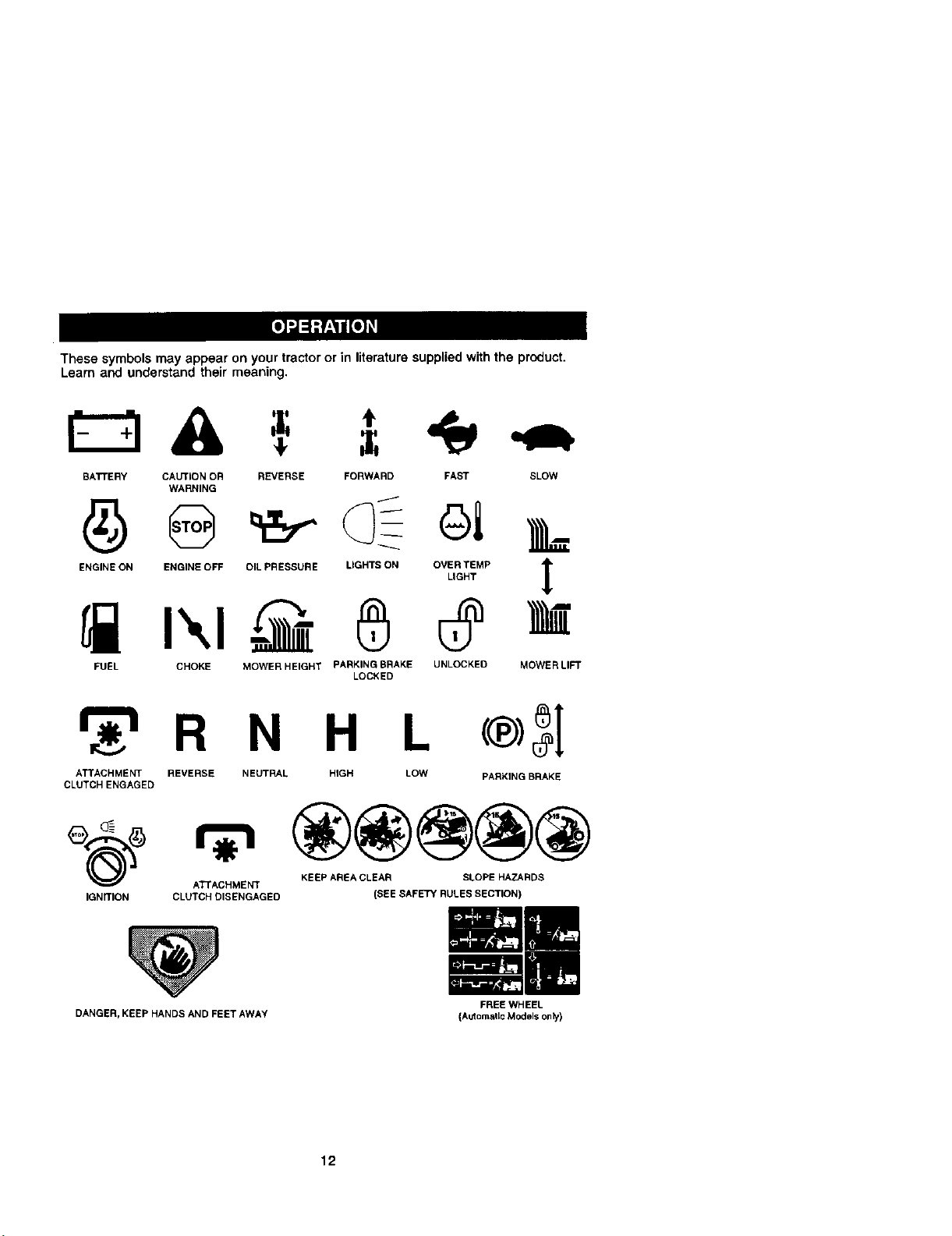
These symbols may appear on your tractor or in literature supplied withthe product.
Learn and understand their meaning,
BATTERY CAUTION OR REVERSE FORWARD FAST SLOW
ENGINE ON ENGINE OFF OIL PRESSURE LIGHTS ON OVER TEMP 1["
FUEL CHOKE MOWER HEIGHT PARKING BRAKE UNLOCKED
WARNING
LIGHT
LOCKED
R N H L
ATTACHMENT REVERSE NEUTRAL HIGH LOW
CLUTCH ENGAGED
e_) ATTACHMENT
IGNITION CLUTCH DISENGAGED
KEEP AREA CLEAR SLOPE HAZARDS
(SEE SAFETY RULESSECTION)
PARKING BRAKE
t
MOWERLI_
DANGER, KEEP HANDS AND FEET AWAY
FREE WHEEL
(AutDrasticModels only)
12
Page 13
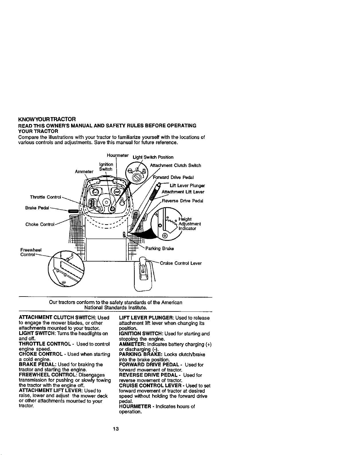
KNOW¥OURTRACTOR
READTHISOWNER'SMANUALANDSAFETYRULESBEFOREOPERATING
YOURTRACTOR
Comparetheillustrations with your tractor to familiarize yourseffwith the locationsof
various controls and adiustments. Save this manual for future reference.
Hourmeter Light Switch Position
Ignition Attachrr_nt Clutch Switch
Ammeter
Brake
Switch
Ddve Pedal
Plunger
Attachment Uft Lever
Reverse Drive Pedal
Choke C Adjustment
Freewheel
Our tractorsconform to the safety standards ofthe American
ATI'ACHMENT CLUTCH SWITCH: Used
to engage the mower blades, or other
attachments mounted to your tractor.
LIGHT SWITCH: Turnsthe headlightson
and off.
THROTI'LE CONTROL- Used to control
engine speed,
CHOKE CONTROL - Used when slatting
a cold engine.
BRAKE PEDAL: Used for braking the
tractor and startingthe engine,
FREEWHEEL CONTROL: Disengages
transmissionfor pushing or slowly towing
the tractor with the engine off.
ATrACHMENT LIFT LEVER: Used to
raise, lower and adjust the mower deck
or other attachments mounted to your
tractor,
- - -- _ _" Indicator
Brake
Contml Lever
National Standards Institute,
LIFT LEVER PLUNGER: Used to release
attachment lift lever when changing its
position.
IGNITION SWITCH: Used for startingand
stopping the engine,
AMMETER: Indicates battery charging (+)
or discharging (-),
PARKING BRAKE: Locks clutcWbrake
intothe brake position.
FORWARD DRIVE PEDAL - Used for
forward movement oftractor.
REVERSE DRIVE PEDAL o Used for
reverse movement oftractor.
CRUISE CONTROL LEVER - Usedto set
forward movement of tractor at desired
speed withoutholding the forward drive
pedal
HOURMETER - Indicates hours of
operation.
13
Page 14
Theoperationofany tractor can result inforeign objects thrown into the
eyes, which can result in severe eye damage. Always wear safety glasses I
or eye shields while operating your tractor or performing any adjustments
or repairs. We recommend a wide visionsafety mask over spectacles, or
standard safety gasses,
HOWTO USEYOURTRACTOR
TO SET PARKING BRAKE
Yourtractoris equipped withan operator
presence sensing switch. When engine
is running,any attempt by the operator to
leave the seat without first settingthe
parking brake willshut off the engine.
1. Depress brake pedal into full "BRAKE"
positionand hold.
2. Place parking brake lever in "EN-
GAGED" positionand release
pressurefrom brake pedal. Pedal
should remain in "BRAKE" position.
Make sure parking brake willhold
tractor secure.
Push-Into SwitchPullOutTo
=Disengaged"-_Engag_
AttachmentClutch
Control.
"Brake"__ j_
"Drive" "Dise_gagecl"_Engaged" Control
position Posff_on Posdion Lever
STOPPING
MOWER BLADES -
• To stop mower bledes,move attach-
ment clutchswitchto "DISENGAGED"
position.
GROUND DRIVE.
• To stop ground ddve, depress brake
pedal into full "BRAKE" position.
IMPORTANT: Forward and reverse drive
pedals retum to neutral positionwhen not
depressed.
ENGINE.
• Move throttle control to slow position.
NOTE: Failureto move throttle controlto
slow positionand allowing engine to idle
before stopping may cause engine to
"backfire".
• Turn ignitionkey to "OFF" positionand
remove key. Always remove key when
leaving tractor to prevent unauthodzed
use.
• Never use choketo stop engine.
IMPORTANT: Leaving the ignition switch
in any position other than "OFF" will
cause the battery to be discharged,
(dead).
NOTE: Under certain conditionswhen
tractor is standing idle with the engine
running, hot engine exhaust gases may
cause =browning" of grass, To eliminate
this possibility,always stop engine when
_Ocppingtractoron grass areas.
AUTION: Always stop tractor
completely, as described above, before
leavingthe operator's position; to empty
grass catcher, etc.
THRO'n'LE CONTROL
Always operate engine at full throttle.
• Operating engine at less than full
throttle reduces the battery charging
rate.
• Fullthrottle offers the best bagging and
mower performance.
TO USE CHOKE CONTROL
Use choke control whenever you are
starting a cold engine. Do not use to start
a warm engine.
• To engage choke control, pull knob out.
Slowly push knob in to disengage.
TO MOVE FORWARD AND
BACKWARD
The direction and speed of movement is
controlledby the forward and reverse
ddve pedals.
1. Start tractor and release parking
brake.
2. Slowly depress forward or reverse
drive pedal to begin movement.
Ground speed increases the further
down the pedal is depressed.
TO USE CRUISE CONTROL
The cruise control feature can be used for
forward travel only.
1. With forward drive pedal depressed to
desired speed, move cruisecontrol
lever forward to "SET" position and
hold while lifting your foot off the
pedal, then release the cruise control
lever.
To disengage the cruise control, pull the
lever backward to "OFF" position, or fully
depress the brake pedal.
TO ADJUST MOWER CuI"rlNG HEIGHT
The positionof the attachment lift lever
determines the cuttingheight.
• Grasp lift lever.
• Press plunger with thumb and move
14 lever to desired position.
Page 15
The cutting height range is approxi-
mately 1-1/2 to 4". The heightsare
measured from the ground to the blade
tip with the engine not running. These
heights are approximate and may vary
depending upon soil conditions, height of
grass andtypee of grass being mowed.
• The average lawn should be cut to
approximately 2-1/2 inches dudng the
cool season and to over 3 inches
during hot months. For healthier and
better looking lawns, mew often and
after moderate growth.
• For best cutting performance, grass
over 6 inches in height should be
mowed twice. Make the first cut
relatively high; the second to desired
height.
TO ADJUST GAUGE WHEELS
Gauge wheels are properly adjusted
when they are slightlyoffthe ground
when mower isat the desired cutting
height in operating position. Gauge
wheels then keep the deck in proper
position to help prevent scalping in most
terrain conditions.
NOTE: Be sure tractor is on a flat level
surface.
1. Lower mower and ad ust mower to
desired cult ng he ght.
2. Remove retainer spring and clevis pin
which secure each gauge wheel bar.
3. Lower gauge wheels to ground. Raise
_auge wheels slightlyto align holes in
racket and gauge wheel bar and
insert clevis pin. Gauge wheels
should be slightly offthe ground.
4. Replace rstamer spring into clevis pin.
5. Be sure allgauge wheels are in the
same setting.
IMPORTANT: Be sure to read ust gauge
wheels f you change the cutting height
ofthe mower deck.
Retainer
TO OPERATE MOWER
Your tractor isequipped with an operator
presence sensing switch. Any attempt by
the operator to leave the seat with the
engine running and the attachment clutch
engaged will shut off the engine.
1. Select desired height of cut.
2. Start mower blades by engaging
attachment clutch control.
TO STOP MOWER BLADES -
dieengaqe attachment clutch control.
• I,CA(.ITION: Do net operate the mower
without either the entire grass catcher, on
mowers so equipped, or the deflector
shield in place.
AttachmentClutch Attachment Lift
SwitchPull OutTo Lever HighPosition
Position
- --\ Deflector
=Enga_ _-" -- Low
/_- . Shield
TO OPERATE ON HILLS
ACAUTION: Do not drive up or down
hills with slopes greater than 15° and do
not drive across any slope.
• Choose the slowest speed before
starting up or downhills.
• Avoid stopping or changing speed on
hills.
• If stopping is absolutely necessary,
push brake pedal quicklyto brake
position and engage perking brake.
• To restart movement, slowly release
parking brake and brake pedal.
• Slowly depress appropriate drive pedal
to slowest setting.
• Make all turns slowly.
TO TRANSPORT
When pushing ortowing your tractor, be
sure to disengage transmission by
placing freewheel control in freewheeling
position. Free wheel control is located at
the rear drawbar oftractor.
1. Raise attachment liftto highest
position with attachment liftcontrol.
2. Pull freewheel control out and into the
slot and release so it is held in the
disengaged position.
• Do not pushor tow tractor at more than
two (2) MPH.
• To re-engage transmission, reverse
above procedure.
NOTE: To protect hood from damage
when transporting your tractor on a track
or a trailer, be sure hood is closed and
secured to tractor. Use an appropriate
means of tying hoodto tractor (rope, cord,
etc.).
15
Page 16
TOWINGCARTSANDOTHERATFACH-
MENTS
Towonlytheattachmentsthatare
recommendedbyandcomplywith
specificationsofthemanufacturerofyour
tractor.Usecommonsensewhentowing.
Tooheavyofaload,whileonaslope,is
dangerous.Tirescanlosetractionwith
thegroundandcauseyoutolosecontrol
ofyourtractor.
BEFORESTARTINGTHEENGINE
CHECKENGINEOILLEVEL
Theengineinyourtractorhasbeen
shipped,fromthefactory,alreadyfilled
withsummerweightoil.
1, Checkengineoilwithtractoronlevel
ground.
2. Removeoilfillcap/dipstickandwipe
clean,reinsertthedipstickandscrew
captight,waitforafewseconds,
removeandreadoillevel.Ifneces-
sery, add oil until "FULL" mark on
dipstickis reached. Do not overfill.
• For cold weather operationyou should
change oil for easier starting(See "OIL
VISCOSITY CHART" inthe Mainte-
nance section of this manual).
• To change engine oil, see the Mainte-
nance section in this manual.
ADD GASOLINE
• Fillfuel tank. Use fresh, clean, regular
unleaded gasoline with a minimum of
87 octane. (Use of leaded gasoline will
increase carbon and lead oxide
deposits and reduce valve life). Do not
mix oil with gasoline. Purchase fuel in
quantities that can be used within 30
days to assure fuel freshness.
IMPORTANT: When operating in tem-
peratures below 32°F(0°C), use fresh,
clean winter grade gasoline to help
insure good cold weather starting.
•,WARNING: -Experienceindicates that
alcohol blended fuels (called gasohol or
using ethanol or methanol) can attract
moisturewhich leads to separation and
formation of acids during storage. Acidic
gas can damage the fuel system of an
engine while in storage. To avoid engine
problems,the fuel system should be
emptied before storage of 30 days or
longer.Drain the gas tank start the
engine and let it ran untilthe fuel lines
and carburetor are empty. Use fresh fuel
nextseason. See Storage Instructions for
additional information. Never use engine
or carburetor cleaner products in the fuel
tank or permanent damage may occur.
16 temperature.
ACAUTION: Fillto bottom of gas tank
filler neck. Do not overfill.Wipe off any
spilled oil or fuel. Do not store, spill or use
gasoline near an open flame.
TO START ENGINE
When startingthe engine for the first time
or ifthe engine has run out offuel, it will
take extra cranking.time to move fuel from
the tank to the engine.
1. Be sure freewheel controlis in the
transmission engaged position.
2, Sit on seat in operating position,
depress brake pedal and set parking
brake.
3. Move attachment clutch to =DISEN-
GAGED" position.
4. Move throttle controltofast position
5. Pull choke controlout for a cold
engine start attempt. For a warm
engine start attempt the choke control
may not be needed.
NOTE: Before starting,read the warm and
cold starting pmceduras below.
6. Insert key into ignitionand turn key
clockwiseto "START" position end
release key as soon as engine starts.
Do not run starter continuouslyfor
more than fifteen seconds per minute.
If the engine does not start after
several attempts, push choke control
in, wait a few minutes and try again. If
engine stilldoes not start, pullthe
choke controlout and retry. ,
WARM WEATHER STARTING (50 F and
above)
7. When engine starts, slowlypush
choke control in until the engine
begins to runsmoothly. If the engine
starts to run roughly,pull the choke
control out slightlyfor a few seconds
and then continue to pushthe control
in slowly.
• The attachments and ground drive can
now be used. If the engine does not
accept the load, restartthe engine and
allow it to warm up for one minute
using tho choke as described above.
COLDWEATHER STARTING (50 F and
below)
7. When engine starts, slowly push
choke control in until the engine
begins to run smoothly. Continue to
push the choke controlin small steps
allowing the engine to accept small
changes =nspeed and load, untilthe
choke control is fullyin. If the engine
starts to runroughly, pullthe choke
controlout slightlyfor a few seconds
and then continue to push the control
in slowly. This may requirean engine
warm-up period from several seconds
to several minutes, depending on the
Page 17
AUTOMATICTRANSMISSION WARM UP
Before drivinq the unit in cold weather,
the transmission should be warmed up as
ictiows:
1. Besure the tractor is on level ground.
2. Release the parking brake and let the
brake slowly returnto operating
position.
3. Allow one minute for transmissionto
warm up. This can be done during the
engine warm up period.
• The attachments can be used during
the engine warm-up pedod after the
transmissionhas been warmed up and
may require the choke control be
pulled out slightly.
NOTE: if at a high altitude (above 3000
feet) or in cold temperatures (below 32 F)
the carburetor fuel mixture may need to
be adjusted for best engine pedormance.
See =TOADJUST CARBURETOR" inthe
Service and Adjustments section of this
manual.
PURGETRANSMISSION
•,CAUTION: Never engage or disengage
freewheel lever whilethe engine is
running.
To ensure proper operation and perfoh
mance, it is recommendedthat the
transmissionbe purged before operatincj
tractorfor the first time This procedurew=t
remove any trapPed air insidethe trans-
missionwhich may have developed during
shippingof your tractor.
IMPORTANT: Should yourtransmission
requireremovalfor sewice or replacement,
it shouldbe purged after rainstallation
before operatingthe tractor.
1. Place tractor safely on level surface
with engine off and parkingbrake set.
2. Disengage transmission by placing
freewheel control in freewheeling
position(See =TOTRANSPORT" in
this section of manual).
3. Sittingin the tractor seat, start engine.
After the engine is running, move
throttle controlto stow position.
Disengage parking brake.
4. Depress forward ddve pedal to full
forward position and hold for five (5)
seconds and release pedal. Depress
reverse drive pedal to full reverse
position and hold for five (5) seconds
and release pedal. Repeat this
procedure three (3) times.
NOTE: During thisprocedurethere will be
no movementof drivewheels.The air is
being removed from hydraulicdrive
system.
5. Shut- off engine and set parkk_g
brake.
6. Engage transmission by placin_
freewheel control in driving position
(See "TO TRANSPORT" inthis section
of manual).
7, Sittingin the tractor seat, start engine.
After the engine is running, move
thro_le controlto half (1/2) speed.
Disengage parking brake.
8, Drive tractorforward for approximately
five feet then backwards forfive feet.
Repeat this ddving procedure three
times.
Your tractor is now purgedand now ready
for normal operation.
MOWINGTIPS
• Mower should be propedy leveled for
best mowing performance. See =TO
LEVEL MOWER HOUSING" in the
Service and Adjustments section of this
manual
• The left hand side of mower should be
used for trimming.
• Drive sothat clippings are discharged
onto the area that has been cut. Have
the cut area to the right of the tractor.
This will result in a more even distribu-
tion of clippingsand more uniform
cutting.
• When mowing large areas, start by
turningto the right so that clippingswill
discharge away from shrubs,fences,
driveways, etc. After one ortwo
rounds, mow in the opposite direction
making left hand turns untilfinished.
• If grass is extremely tall, it should be
mowed twice to reduce load and
possiblefire hazard from dried clip-
pings. Make firstcut relatively high;the
second to the desired height.
, Do not mow grass when it is wet. Wet
grass willplug mower and leave
undesirable clumps. Allow grass to dry
before mowing.
• Alwaysoperateenglne atfuUthrotUe
when mowing to assure better mowing
performance and proper discharge of
material. Regalate ground speed by
selecting a low enough gear to give the
mower cutting performance as well as
the quality of cut desired.
• When operating attachments, select a
ground speed that will suit the terrain
and give best performance of the
attachment being used.
17
Page 18
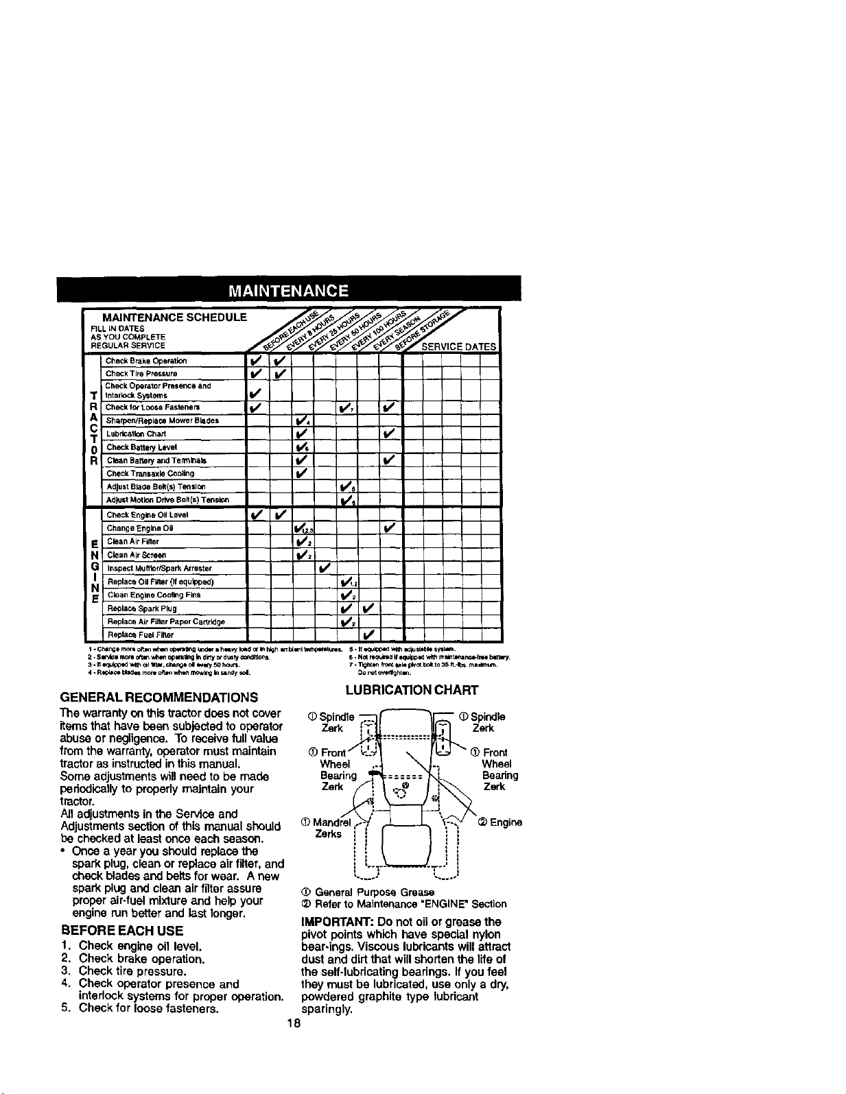
MAINTENANCESCHEDULE
FiLL iN DATES
AS YOU COMPLETE
REGULAR SERVICE SERVICE DATE
Check Brake Ope_tlen V O I_
CheCKTire pressure _ V p
CheCk Operator Presence and
interlock Systems I/
Check Ic_ LOOSeFasteners _ VsT ll_
Sha_0en!Replace Mower Blades I/4
Lubrleatlon Chart II/ fl_
Check Battery Level
Clean Batter/and Temlleala _
Check Tmnsaxle Cooling I/
Adjust Bla_e Belt(s) TenSt_ t/s
Ad_st Motion Drive Belt(s) Tensle_ _?
Cheek Engll_e Oil Level if If
Change Engine Oil I1_1_,_ V /
Clean Air Filter I/2
Clean Air Screen f/2
Inspect Muffler/Spa_ Arre_ter
Replace O!l F_er (If equipped) {1_1.;
Clean Engine Cooling Fins 11/2
Replace Spa_k Plug _ I/
ReplaCe Air Fi_terPaper Cartridge (i/_
Replace Fuel Fitter
I -Chla_g I rnc4_Dfton whqm o_ting I_nd_-i h mvy Iohd Or In I_h I_ I_t _ S - If _lpped wtffl I,d_b_e _ysb*_.
2. $o_i_1 mo_ oPm_whtn opnSng in dirty =_dus_y_n_ns 6. Not r_ln_lf *_ippe_ w_ mmts_ar_lr=_ b_
e. I1 =_:_lp_ v_ ol1111t_,d'_mgo ol _y 50 hours 7. _ghtsn trout _k* p_t bY_tto3,$_.-I_S mldn_um
4. Repro* _ad_ n'_'* olin wh*n r_ In s_roy sol Donot overd_h=*n.
GENERAL RECOMMENDATIONS
The warrantyonthis tractordoes not cover
itemsthat have been subjected to operator
abuse or negligence. To receivefull value
from the warranty, operator must maintain
tractor as instructedinthis manual.
Some adjustmentswill need to be made
pededicallyto propedymaintain your
tractor.
All adjustmentsinthe Service and
Adjustmentssection of this manual should
be checked at least once each season.
• Once a year you should replace the
spark plug, clean or replace airfilter, and
check bladesand beltsfor wear. A new
spark plug and clean air filter assure
proper air-fuel mixtureand help your
engine runbetter and last longer.
BEFORE EACH USE
1. Check engine oil level.
2. Check brake operation.
3. Check tire pressure.
4. Check operator presence and
interlock systems for proper operation.
5. Check for loose fasteners.
_) General Purpose Grease
_) Refer to Maintenance "ENGINE" Section
IMPORTANT: Do not oil or grease the
pivot points which have special nylon
bear-ings. Viscous lubricants will attract
dust and dirt that will shorten the llfe of
the self-lubricating bearings. If you feel
they must be lubricated,use only a dry,
powdered graphite type lubricant
sparingly.
18
LUBRICATION CHART
(i) Spindle ' _) Spindle
Zerk Zerk
Wheel Wheel
Bearing Bearing
Zerk Zerk
Zerks
L._.J L...o.
_) Froct
Page 19

TRACTOR
Always observe safety rules when
performing any maintenance.
BRAK_ OPERATION
If tractor requiresmore than six (6) feet
stopping distance at high speed in
highest gear, then brake must be ad-
justed. (See "[0 ADJUST BRAKE" in the
Service and Adjustments section ofthis
manual).
TIRES
• Maintain proper air pressure in all tires
(See "PRODUCT SPECIFICATIONS"
section of this manual).
• Keep tires free of gasoline, oil,or insect
control chemicals which can harm
rubber.
• Avoid stumps, stones, deep ruts,sharp
objeu-'tsand other hazards that may
cause tire damage.
NOTE: To seal tire punctures and prevent
flat tires due to slow leaks, tire sealant
may be purchasedfrom your local parts
dealer. Tire sealant also prevents tire dry
rot and corrosion.
OPERATOR PRESENCE SYSTEM
Be sure that operator presence and
intedocksystems are working properly. If
your tractor does not function as de-
scribed below, repair the problem
immediately.
• The engine should notstart unless the
brake pedal is fully depressed and
attachment clutchcontrol is in the
disengaged position.
• When the engine is running, any
attempt by the operator to leave the
seat withoutfirst setting the parking
brake should shut off the engine.
• When the engine is running and the
attachment clutch is engaged, any
attempt by the operator to leave the
seat should shut off the engine.
• The attachment clutch should never
operate unless the operator is in the
seat.
BLADE CARE
For best resultsmower blades must be
kept sharp. Replace bent or damaged
blades.
BLADE REMOVAL
1. Raise mower to highest positionto
allow access to blades.
2. Remove hex bolt, lock washer and flat
washer securing blade.
3. Install new or resharpenod blade with
trailingedge uptowards deck as
shown.
IMPORTANt': To ensure proper assembly,
center hole in blade must align with star
on mandrel assembly.
4. Reassemble hex bolt, lock washer
and fiat washer in exact order as
shown.
5. Tighten bolt securely (45-55 Ft. Lbs.
torque).
TrailingEdgeUp _ _ Mandrel
_________Star_ Assembly
Flat Washer _-_._ Center
Lock__ I_lo'e
Washer ./"_ Blade
--(Grade 8)"
*A Grade8 heattreatedboltcanbe
identifiedby sixlinesontheboffhead.
IMPORTANT: Blade bolt is grade 8 heat
treated.
TO SHARPEN BLADE
NOTE: We do rot recommend sharpen-
ing blade - but if you do, be sure the
blade is balanced.
Care should be taken to keep the blade
balanced. An unbalanced blade will
cause excessive vibration and eventual
damage to mower and engine.
• The blade can be sharpened with a file
or on a gdndingwheel. Do not attempt
to sharpen while on the mower.
• To check blade balance, you will need
a 5/6" diameter steel bolt, pin, or a cone
balancer. (When usinga cone bal-
ancer, follow the instructions supplied
with balancer.)
NOTE: Do not use a nail for balancing
blade. The lobes of the center hole may
appear to be centered, but are not.
• Slide blade on to an unthreaded
portionof the steel bolt or pin and hold
the bolt or pin parallel with the ground.
If blade is balanced, it should remain in
a horizontal position. If either end of
the blade moves downward, sharpen
the heavy end untilthe blade is
balanced.
B,ade
or Pin
19
Page 20

BA'n'ERY
Yourtractorhas a battery charging system
which is sufficient for normal use. How-
ever periodic charging of the battery with
an automotive charger will extend ts fe.
• Keep battery and terminals clean.
• Keep battery boifstight.
• Keep small vent holes open.
• Recharge at 6-10 amperes for 1 hour.
NOTE: The odginal equipment battery on
yourtractor is maintenance free. Do not
attempt toopen or remove caps or covers.
Adding or checking level of electrolyte is
not necessary.
TO CLEAN BATTERY AND TERMINALS
Corrosion and dirton the battery and
terminals can cause the battery to "leak"
power.
1. Remove terminal guard.
2. Disconnect BLACK battery cable first
then RED battery cable and remove
batteryfromtractor.
3. Rinse the battery with plain water and
dry.
4. Clean terminals and battery cable
ends with wire brush untilbright.
5. Coat terminals with grease or petro-
leum jelly.
6. Reinstall battery (See =REPLACING
BATTERY" in the SERVICE AND
ADJUSTMENTS section of this
manual).
V-BELTS
Check V-belts for deterioration and wear
after 100 hours of operation and replace
ifnecessary.The beltsare notadjustable.
Replace belts ifthey begin to slip from
wear.
TRANSAXLE COOLING
The transmission fan and coolingfins
should be kept clean to assure proper
cooling.
Do not attempt to clean fan or transmis-
sion while engine is runningor while the
transmissionis hot. To prevent possible
damage to seals, do not use high
pressurewater or steam to clean
transaxle.
• Inspect coolingfan to be sure fan
blades are intact and clean.
• Inspect cooling fins for dirt, grass
clippings and other matedals. To
prevent damage to seals, do not use
compressed air or high pressure
sprayer to clean cooling fins.
TRANSAXLE PUMP FLUID
The transaxle was sealed at the factory
and fluid maintenance is not required for
the life of the transaxle. Should the
transaxla ever leak or require servicing,
contact your nearest authorized service
center/department.
ENGINE
LUBRICATION
Only use high quality detergent oil rated
with API serviceclassificationSF-SJ.
Select the oil's SAE viscositygrade
according to your expected operating
temperature.
NOTE: Although multi-viscosityoils
(5W30, 10W30 etc.) improve starting in
cold weather, these multi-viscosityoils
will result in increased oil consumption
when used above 32°E Check your
engine oil level more frequently to avoid
possible engine damage from running
low on oil.
Change the oil after every 50 hoursof
operationor at least once a year if the
tractor is not used for 50 hours in one
year.
Check the crankcase oillevel before
starting the engine and after each eight
(8) hours of operation. Tighten oil fill cap/
dipstick securely each time you check the
oil level.
TO CHANGE ENGINE OIL
Determine temperature range expected
before oil change. All oilmust meet API
service classification SF-SJ.
• Be sure tractor is on level surface.
• Oil will drain more freely when warm.
• Catch oil in a suitable container.
1. Remove oilfill cap/dipstick. Be careful
notto allow dirtto enter the engine
when changing oil.
2. Remove cap from end of drain vane
and installthe drain tube onto the
fitting.
3. Unlock drain valve by pushing inward
slightly and turning counterclockwise.
4. To open, pull out on the drainvalve.
5. After oil has drained completely, dose
and lock the drain valve by pushing
inward and tuming clockwise until the
pin is in the locked position as shown.
20
Page 21

6. Remove the drain tube and replace
the cap onto to the end of the drain
valve.
7. Refill engine with oil through oil fill
dipsticktube. Pour slowly. Do not
overfill. For approximate capacity
sea "PRODUCT SPECIFICATIONS"
section of this manual.
8. Use gauge on oil fill cap/dipstick for
checking level. Be sure dipstickcap
is tightened securely for accurate
reading. Keep oilat "FULL" line on
dipstick.
Oil Drain Valve
Closed=
Cap_
CLEAN AIR SCREEN
Air screen must be kept free of dirtand
chaff to prevent engine damage from
overheating. Clean witha wire brush or
compressed air to remove dirt and
stubborndried gum fibers.
CLEAN AIR INTAKE/COOLING AREAS
To insure proper cooling, make sure the
grass screen, cooling fins, end other
external surfaces of the engine are kept
clean at all times.
Every 100 hoursof operation (more often
under extremely dusty, dirtyconditions),
remove the blower housing and other
coolingshrouds. Clean the cooling fins
and external surfaces as necessary. Make
sure the cooling shrouds are reinstalled.
NOTE: Operating the engine with a
blocked grossscreen, dirtyor plugged
coolingfins, and/or cooling shrouds
removed willcause engine damage due
to overheating.
AIR FILTER
Your engine will not runproperly using a
dirty air filler. Clean the foam pre-cleaner
after every 25 hours of operation or every
season. Service paper cartridge every
100 hours of operation or every season,
whichever occurs first.
Service air cleaner more offer under
dusty conditions.
1. Remove knobs and cover.
TO SERVICE PRE-CLEANER
2. Wash it in liquid detergent and water.
3. Squeeze it dry in a clean cloth.
4. Saturate it in engine oil. Wrap it in
clean, absorbent cloth and squeeze to
remove excess oil.
NOTE: Ifvery dirty or damaged, replace
pre-cleaner.
TO SERVICE CARTRIDGE
5. Clean cartridge by tapping gently on
flat surface. If very dirty or damaged,
replace cartridge.
6. Reinstall precleener cartridge, cover
and secure with knobs.
IMPORTANT: Petroleum solvents, such
as kerosene, are not to be used to clean
the cartridge. They may cause deteriora-
tion of the cartridge. Do not oil cartridge.
Do not use pressurized air to clean or dry
cartridge.
Foam _Cartddge
Pre-Cleaner
ENGINE OIL FILTER
Replace the engine oil filler every season
or every other oil change if the tractor is
used more than 100 hours in one year.
21
Page 22

MUFFLER
Inspectand replace corroded mufflerand
spark arrester (if equipped) as it could
create a fire hazard and/or damage.
SPARK PLUGS
Replace spark plugs at the beginning of
each mowing season or after every 100
hours ofoperation, whichever occurs first.
Spark plugtype and gap setting are
shown in "PRODUCT SPECIFICATIONS"
section ofthis manual.
IN-LINE FUEL FILTER
The fuel filter should be replaced once
each season. If fuel filter becomes
clogged, obstructingfuel flow to carbure-
tor, replacement is required.
1. With engine cool, remove filter and
plug fuel line sections.
2. Place new fuel filter in positionin fuel
line with arrow pointing towards
carburetor.
3. Be sure there are no fuel line leaks
and damps are propedy positioned.
4. Immediately wipe up any spilled
gasoline.
Clamp
FuelFilter_
CLEANING
• Clean engine, battery, seat, finish, etc.
of all foreign matter.
• Keep finished surfaces and wheels free
of all gasoline, oil, etc.
• Protect painted surfaces with automo-
tive type wax.
We do not recommend usinga garden
hose to clean your tractor unless the
electdcal system, muffler, air filter and
carburetor are covered to keep water out.
Water in engine can result in a shortened
engine life.
22
Page 23

_CAUTION: BEFORE PERFORMING ANY SERVICE OR ADJUSTMENTS:
1, Depress brake pedal fully and set parking brake•
2. Place attachment clutch in =DISENGAGED" position.
3. Turn ignition key "OFF" and removekey.
4, Make sure the blades and all moving parts have completely stopped.
5. Disconnect spark plug wire from spark plug and place wire where it cannot
come in contact with plug,
TRACTOR
TO REMOVE MOWER
1. Place attachment clutch In =DISEN-
GAGED" position,
2. If equipped, tum height adjustment
knob to lowest setting.
3. Lowermower to its lowest position.
4. Disengage belt tension md from lock
bracket.
_,CAUTION: Rod is spdng loaded. Have
a tight gdp on rod and release slowly.
5. Remove retainer spring holding anti-
swaybar to chassis bracket and
7. Remove retainer springsfrom
suspension arms at deck and disen-
gage arms from deck.
8, Raise attachment liftto its highest
position,
9. Slide mower forward and remove belt
from electric clutch pulley.
10.Slide mower outfrom under dght side
oftractor.
TO INSTALL MOWER
Follow procedure described in =INSTALL
MOWER AND DRIVE BELT" in the
Assembly section of this manual.
disengage anti-swaybar from bracket.
6. Remove four retainer spdngs from
front plate assembly and remove
plate.
Electric
Clutch Pulley
Front
Plate
BeltTension
Rod
(Disengaged_,,
Positon /7
Chassis
Suspension
Front Mower
Bracket
Retainer
Anti-Sway
Bar
(Both Sides)
Bracket
23
Page 24

TOLEVELMOWERHOUSING
Adiust the mower while tractor is parked
on level ground or driveway. Make sure
tires are properly inflated (See ROD-
UCT SPECIFICATIONS" section of this
manual). If tires are over or
undednflated, you will not propedy adjust
your mower.
SIDE-TO-SIDE ADJUSTMENT
• Raise mower to its highest position.
• At the midpointof both sides of mower,
measure height from bottom edge of
mower to ground. Distance "A* on
both sides of mower should be the
same or within 1/4" of each other.
• If adjustment is necessary, make
adjustment on one side of mower only.
• To raise one side of mower, tighten I_
link adjustment nut on that side.
• To lower one side of mower, loosen lift
link adiustment nut on that side.
NOTE: Each full turn of adjustment nut
will change mower height about 1/8".
• Recheck measurements after adjust-
ing.
BottomEdgeof BottomEdgeof
Mowerto Ground Mowerto Ground
-p
• Before making any necessary adjust-
merits, checkthat both front links are
equal in length.
• If links are not equal in length, adjust
one link to same length as otherlink.
• To lower front of mower loosen nut"E"
on both front linksan equal number of
turns.
• When distance"D" is 1/S"to 1/2" lower
at front than rear, tighten nuts "F"
against trunnionon both front links.
• To raise front of mower, loosen nut"F"
from trunnion on bothfront links.
Tighten nut "E" on both front links an
equal number of turns.
• When distance "D" is 1/8* to 112"|ower
at front than rear,tighten nut =F"against
trunnion on both front links.
• Recheck side-to-side adiustment.
o
BOTH FRONT LINKS MUST BE EQUAL
IN LENGTH
Suspen_Don
Lilt Link
Adjustment
Nut
FRONT-TO-BACK ADJUSTMENT
IMPORTANT: Deck must be level side-to-
side.If the following front-to-back adjust-
ment is necessary, be sure to adjust both
front links equally so mower will stay
level side-to-side.
To obtain the best cuttingresults,the
mower housing should be adjusted so
thatthe frontis approximately 1/8" to 1/2"
lower than the rear when the mower Is in
its highest position.
Check adjustmenton right side of tractor.
Measure distance =D" directlyin front and
behind the mandrel at bottom edge of
mower housing as shown.
Front Plate Trunnion
Assembly
TO REPLACE MOWER DRIVE BELT
MOWER DRIVE BELT REMOVAL
1. Parktractor an a level surface.
Engage parking brake.
2. Lower mower to its lowest position.
3. Disengage belt tension rodfrom lock
bracket.
ACAUTION: Rod Is spdng loaded. Have
a firm grip an rod an release slowly.
4. Remove screws from R.H. mandrel
cover and remove cover.
24
Page 25

5. Remove any dirt or grass clippings
which may have accumulated around
mandrels and entire upper deck
surface.
6. Disconnect R.H. suspensionarm from
rear deck bracket by removing
retainer spdng.
7, Carefully roll belt over the top of R.H.
mandrel pulley.
8. Remove belt from electdc clutch
pulley.
9, Remove belt from idler pulleys.
10.Check primary idler arm and two
idlers to see that they rotatefreely.
11.Be sure spring is securely hooked to
primary idler arm and spring arm.
MOWER DRIVE BELT INSTALLATION
12.Install belt in both idlers,
13.Install new belt onto electric clutch
pulley,
14.Carefully roll belt into upper groove of
R.H. mandrel pulley.
15.Carefully check belt routing making
sure belt is in the grooves correctly.
16.Reconnect R.H. suspension arm to
rear deck bracket with retainer spring,
17.Reassemble R.H. mandrel cover.
18.Engage belt tension rod by pushing
rod into locking bracket.
BeltTension R.H. Mandrel Electdc
Rod
(Disengaged Cover_ Clutch
Posen).?
4. Carefully roll belt off L.H. mandrel
pulley.
5. Remove belt from center mandrel
pulley, idler pulley, and R.H. mandrel
pulley.
6. Remove any dirt or grass which may
have accumulated around mandrels
and entire upper deck surface.
7. Check secondary idler arm and idler
pulley to see that they rotate freely.
8. Be sure springis hooked in secondary
idler arm and secondary spring arm.
9. Install new belt in lower groove of R.H.
mandrel pulley, idler pulley, and
center mandrel pulley as shown.
10.Carefully roll belt over L.H. mandrel
pulley. Make sure belt is in all
grooves properly.
11.Reinstall L.H. mandrel cover.
12.Reinstall mower to tractor (See
"INSTALL MOWER AND DRIVE
BELT" in the Assembly section of this
manual).
13. Reassemble mower drive belt (See
"TO REPLACE MOWER DRIVE BELT"
in this section of this manual).
LH. Secondary Idler Arm
_ /Secondary
SpdngArm
let Pulley Spring
Mandrel
Suspension
Arm Primary
Idler Arm
TO REPLACE MOWER BLADE DRIVE
BELT
Parkthe tractoron level surface. Engage
parking brake.
1. Remove mower drive belt (See "TO
REPLACE MOWER DRIVE BELT" in
this section of this manual).
2. Remove mower (See "TO REMOVE
MOWER" in this section of this
manual).
3. Remove screws from L.H. mandrel
cover and remove covet.
TO ADJUST BRAKE
Yourtractor is equipped with an adjust-
able brake system which is mounted on
the side ofthe transaxle.
iftractorrequires mare than six(6) feet
stoppingdistance at high speed in highest
gear on a level dry concrete or paved
surface, then brake must be adjusted.
1. Depress clutch/brake pedal and
engage parking brake.
2. Measure distance between brake
operating arm and nut"A" on brake
rod.
3. Ifdistance is other than 1-11/16",
loosen jam nut and turn nut "A" until
distance becomes 1-1f/16". Re-
tightenjam nut against nut "A".
25
Page 26

4. Roadtesttractorforproperstopping
distanceasstatedabove.Readjustif
necessary.Ifstoppingdistanceis still
greater than six (6) feet in highest
gear, further maintenance is neces-
sary. Contact your nearest autho-
rized service center/department.
With Parking Brake "Engaged"
AfTn
Do Not t :h this nut. It further brake
ad_stment is necessary cm_tact yc_r nearest
authorized service center/department
TO REPLACE MOTION DRIVE BELT
Parkthe tractor on level surface. Engage
parking brake. Forassistance, there is a
belt installation guide decal on bottom
side of left footrest.
1. Remove mower (See "I'O REMOVE
MOWER" in this section of this
manual.)
2. Disconnect clutch wire harness.
3. Remove clutch Iocator.
4. Remove belt from stationary idler and
clutching idler.
5. Pull belt slack toward rear of tractor.
Carefully remove belt upwards from
transmission input pulley and over
coolingfan blades.
6. Pull belt toward front of tractor and
remove downwards from around
electric clutch.
7. Install new belt by reversing above
procedure.
Clutch
Clutch
Clutching_
idler
Stationaryj
Idler
EIsutr_c_ !
Transmission "_....
InputPulley-- 4.___,
_-Locator
Ct_tch
Wire Hamess
TRANSMISSION REMOVAIJREPLACE-
MENT
Should your transmission require
removal for service or replacement, it
should be purged after reinstallationand
beforeoperating the tractor. See =PURGE
TRANSMISSION" in the Operation
section of this manual.
TO ADJUST STEERING WHEEL ALIGN-
MENT
If steedng wheel crossbars are not
horizontal (left to right) when wheels are
positionedstraight forward, remove
steering wheel and reassemble per
instructionsIn the Assembly sectionof
this manual.
FRONT WHEEL TOE-IN/CAMBER
The frontwheel toe-in and camber are
notadjustable on your tractor. If damage
has occurredto affect the front wheel toe-
in or camber, contactyour nearest Sears
or other qualified service center.
TO REMOVE WHEEL FOR REPAIRS
1. Blockup axle securely.
2. Remove axle cover, retaining ring and
washers t_ allow wheel removal Irear
wheel containsa square key - Do not
lose).
3. Repair tire and reassemble.
NOTE: On rear wheels only: align
grooves in rear wheel hub and axle.
Insert square key.
4, Replace washers and snap retaining
dng securely inaxle groove.
5. Replace axle cover.
NOTE: To seal tire puncturesand prevent
flat tires due to slowleaks, tire sealant
may be purchased from your local parts
dealer. Tire sealant also prevents tire dry
rotand corrosion.
(Rear Wheel Only)
26
Page 27

TOSTARTENGINEWITHAWEAK
BATTERY
A,CAUTION: Lead-acid batteries
generate explosive gases. Keep sparks,
flame and smoking materials away from
batteries. Always wear eye protection
when around batteries.
if your battery istoo weak to startthe
engine, it should be recharged. (See
"BATIERY" in the MAINTENANCE
sectionof this manual).
If "jumper cables" are used for emergency
starting,follow this procedure:
IMPORTANT: Yourtractoris equipped
with a 12 volt negative grounded system.
The othervehical must also be a 12 volt
negative grounded system. Do not use
your tractor battery to start other vehicles.
TO ATTACHJUMPER CABLES -
1. Connect each end of the RED cable to
the POSITIVE (+) terminal of each
battery,taking care notto short
against chassis.
2. Connect one end of the BLACK cable
to the NEGATIVE (-) terminal offully
charged battery.
3. Connect the other end of the BLACK
cable to good CHASSIS GROUND,
away from fuel tank and battery.
TO REMOVE CABLES,REVERSE ORDER -
1. BLACK cable first from chassis and
then from the fully charged battery.
2. RED cable last from both batteries.
=Posifi_ =Negative"
_+' /l _l_ / (-)
REPLACING BATTERY
_,CAUTION: Do not shortbattery
terminals by allowing a wrench or any
other object to contact both terminals at
the some time. Before connectingbattery,
remove metal bracelets, wristwatch
bands, rings,etc.
Positiveterminal must be connected first
to prevent sparking from accidental
grounding.
1. Lifthood to raised position.
2. Remove terminal guard.
3. Disconnect BLACK battery cable then
RED battery cable and carefully
remove battery from tractor.
4. Install new battery with terminals in
same position as old battery.
5. Reinstall terminal guard.
6. First connect RED battery cable to
positive (+) battery terminal with hex
bolt and keps nut as shown. Tighten
securely.
7. Connect BLACK grounding cable to
negative (-) battery terminal with
remaining hex bolt and keps nut.
Tighten securely
8. Close terminal access doors.
9. Close hood.
keps Nut
Terminal
Access •
Door_x I_it
_rminal _
Guard__--_ Positive(Red)
I I l -_, Cable
' I I_'_ _'_Negarlve
"_ 1/ (Black) Cable
TO REPLACE HEADLIGHT LAMP
_,CAUTION: When lit, the halogen lamps
get extremely hot. Hold lamp assembly by
the holder and do not touchthe bulb.
1. Raise hood.
2. Disconnect harness from lamp
assembly.
3. Rotate counterclockwise and pull
lamp assembly out of the hole in the
backside of the grill.
4. Insert new lamp assembly and rotate
clockwiseto lock.
5. Reconnect harness to lamp assembly.
6. Close hood.
INTERLOCKS AND RELAYS
Looseor damaged wiring may cause your
tractorto run poorly,stop running,or
preventit from starting.
• Check widng. See electrical wiring
diagram in the Repair Parts section.
TO REPLACE FUSE
Replace with 20 amp automotive-type
plug-in fuse. The fuse holder is located
behind the dash.
TO REMOVE HOOD AND GRILL AS-
SEMBLY
1. Raise hood.
2. Unsnap headlight wire connector.
3. Stand in front of tractor. Grasp hood at
sides, tilt toward engine and liftoff of
tractor.
4. To replace, reverse above procedure.
27
Page 28

Hood
Headlight Wire
ctor
ENGINE
Maintenance,repair,or replacementof the
emissioncontroldevicesand systems,which
are being done at the customers expense,
may be performed by any non-roed engine
repairestablishment or indMdual. Warranty
repairsmustbeperformedby an authorized
engine manufacturer's serviceoutlet.
TO ADJUSTTHRO'n'LE CONTROL
CABLE
The throttlecontrol has been preset at the
factory and adjustment should not be
necessary. Check adjustment as de-
scribedbelow before loosening cable. If
adjustment is necessary, proceed as
follows:
1. With engine not running, move throttle
controllever tofast position.
2. Check thatswivel isagainst stop. If it is
not, loosen cable clamp screw and
pull cable back until swivel is against
stop. Tighten cable clamp screw
securely.
TO ADJUST CHOKE CONTROL
The choke controlhas been preset at the
factoryand adjustment should not be
necessary. Check adjustment as de-
scribed below before loosening cable. If
adjustment is necessary, proceed as
follows:
1. With engine not running, move choke
control (located on dash panel) to full
choke position.
2. Loosen knob and remove cover
assembly from air cleaner.
3. Choke should be closed. Ifit is not,
loosen casing clamp screw and move
choke cable until choke is completely
closed. Tighten casing clamp screw
securely.
4. Replace air cleaner cover assembly
and tighten knob.
TO ADJUST CARBURETOR
Yourcarburetor is not adjustable. If your
engine does not operate propedy due to
suspected carburetor problems, take your
tractor to an authorized service center for
repair and!or adjustment.
High speed stop isfactory adjusted. Do
not adjust - damage may result.
IMPORTANT: Never tamper with the
engine governor,which is factory set for
proper engine speed. Overspeeding the
engine above the factory high speed
setting can be dangerous. If you think the
engine-govemed high speed needs
adjusting, contacta Sears orotherquardied
servicecenter,,which has proper equip-
ment and experience to make any
necessary adjustments.
Screw
Clamp S I1_
28
Page 29

Immediatelyprepareyour tractorfor
storage at the end of the season or ifthe
tractor will not be used for 30 days or
more.
_CAUTION: Never storethe tractorwith
gasoline in the tank insidea building
where fumes may reach an open flame or
spark. Allow the engine to cool before
storingin any enclosure.
TRACTOR
Remove mower from tractor for winter
storage. When mower isto be stored for
a period of time, clean it thoroughly,
remove all dirt, grease, leaves, etc. Store
in a clean, dry area.
1. Clean entire tractor (See =CLEANING"
in the Maintenance section of this
manual).
2. inspect and replace belts, if necessary
(See belt replacement instructions in
the Service and Adjustments section
of this manual).
3. Lubricateas shown in the Mainte-
nance section ofthis manual.
4. Be sure that all nuts, bolts and screws
are securely fastened. Inspect moving
parts for damage, breakage and wear.
Replace if necessary.
5. Touch up all rusted or chipped paint
surfaces; sand lightly before painting.
BATI'ERY
• Fully charge the battery for storage.
• After a period oftime instorage, battery
may require recharging,
• To help prevent corrosion end power
leakage duringlong periods of storage,
battery cables should be disconnected
and battery cleaned thoroughly (see
"TO CLEAN BA11-ERY AND TERMI-
NALS" in the Maintenance section of
this manual).
• After cleaning, leave cables discon-
nected and place cables where they
cannot come in contactwith battery
terminals.
• If battery is removed from tractor for
storage, do not store battery directly on
concrete or damp surfaces.
ENGINE
FUEL SYSTEM
IMPORTANT: It is important to prevent
gum deposites from forming in essential
fuel system parts such as carburetor,fuel
hose, or tank dudngstorage. Also,
expedance indicates that alcohol
blended fuels (called gasohol or using
ethanol or methanol) can attract moisture
which leads to separation and formation
of acids dudng storage. Acidic gas can
damage the fuel system of and engine
while in storage.
1. Drain the fuel tank.
2. Start the engine and let it mn until the
fuel lines and carburetor are empty.
• Never use engine or carburetor cleaner
products in the fuel tank orpermanent
damage may occur.
• Use fresh fuel next season.
NOTE: Fuel stabilizer is an acceptable
alternative in minimizingthe formation of
fuel gum depositsduring storage. Add
stabilizerto gasoline in fuel tank or
storage container. Alwaysfollowthe mix
ratio found on stabilizer container. Run
engine at least 10 minutes after adding
stabilizer to allow the stabilizer to reach
the carburetor. Do notdrain the gastank
and carburetorif using fuel stabilizer.
ENGINE OIL
Drain oil (with engine warm) and replace
with clean engine oil. (See "ENGINE" in
the Maintenance section of this manual).
CYLIN DER(S)
1. Remove spark plug(s).
2. Pour one ounce of oil through spark
plug hole(s) into cylinder(s).
3. Turn ignition key to"START" position
for a few seconds to distribute oil.
4. Replace with new spark plug(s).
OTHER
• Do not store gasoline from one season
to another.
• Replace your gasoline can ff your can
startsto rust. Rustand/or dirt in your
gasoline will cause problems.
• If possible, store your tractor indoors
and cover itto give protectionfrom dust
and dirt.
• Cover your tractor with a suitable
protective cover that does not retain
moisture. Do not use plastic. Plastic
cannot breathe which allows conden-
sation to form and will cause your
tractor to rust.
IMPORTANT: Never cover tractor while
engine and exhaust areas are still warm.
29
Page 30

TROUBLESHOOTINGCHART
PROBLEM CAUSE
Will not start t. Out of fuel.
2.
Engine not "CHOKED"
properly.
3.
Engine flooded.
4.
Bad spark plug.
5.
Dirty air filter.
6.
Dirty fuel rifler.
7.
Water in fuel.
8.
Loose or damaged wiring.
9.
Carburetor out ofadjustment.
10.Engine valves out of
adjustment.
CORRECTION
1. Fillfuel tank.
2. See "TO START ENGINE"
in Operation section.
3. Wait several minutes before
attempting to start.
4. Replace spark plug.
5. Clean/replace air filter.
6. Replace fuel filter.
7. Drain fuel tank and carbure-
tor, refilltank with fresh
gasoline and replace fuel
filter.
8. Check all widng.
9. See "To Adjust Carburetor"
in Service Adjustments
section.
10.Contact a Sears orother
qualified service center.
Hard to start
Engine will not
turn over
iEngine clicks but 1. Weak or dead battery. 1. Recharge or replace battery.
NIIInot start 2. Corroded battery terminals. 2. Clean battery terminals.
1. Dirtyair filter.
2. Bad spark plug.
3. Weak or dead battery.
4. Dirty fuel filter.
5. Stale or dirty fuel.
6. Loose or damaged wiring.
7. Carburetor out of adjustment.
8. Engine valves out of
adjustment.
1; Brake pedal not depressed.
2. Attachment clutch is
engaged.
3. Weak or dead battery.
4. Blown fuse.
5. Corroded battery terminals.
6. Loose or damaged wiring.
7. Faulty ignitionswitch.
8. Faultysolenoid or starter.
9. Faulty operator presence
swflch(es).
3. Loose or damaged wiring. 3. Check all wiring.
4. Faultysolenoid or starter. 4. Check]replace solenoid or
1. Clean/replace air filter.
2. Replace spark plug.
3. Recharge or replace battery.
4. Replace fuel filter.
5. Drain fuel tank and refillwith
fresh gasoline.
6. Check all wiring.
7. See "To AdjustCarburetor_in
Service Adjustments
section.
8. Contact a Sears or other
qualified service center.
1. Depress brake pedal.
2. Disengage attachment
clutch.
3. Recharge or replace battery.
4. Replace fuse.
5. Clean battery terminals.
6. Check all wiring.
7. Check/replace ignition
switch.
8. Check]replace solenoid or
starter.
9. Contact a Sears or other
qualified service center.
starter.
"oss of power 1. Cutting too much grass]too 1. Set in "Higher Cut" position/
fast. reduce speed.
2. Throttle in "CHOKE" 2. Adjustthrottle control
position.
30
Page 31

TROUBLESHOO_NG CHART
PROBLEM
LOSSof power
(continued)
Excessive
vlbr_Ion
CAUSE CORRECTION
3. Build-up of grass, leaves
and trash under mower.
4. Dirty air filler.
5. Low oil leveVdirty oil.
6. Faultyspark plug.
7. Dirtyfuel filter.
8. Stale or dirtyfuel.
9. Water infuel.
10.Spark plug wire loose.
t 1.Dirty engine air screen/fins.
12.Dirty/clogged muffler.
13.Loose or damaged wiring.
14.Carburetor out of
adjustment.
15.Engine valves out of
adjustment.
1. Worn, bent or loose blade.
2. Bent blade mandrel.
3. Loose/damaged part(s).
3. Clean underside of mower
housing.
4. Clean/replace air filter.
5. Check oil level/change oil.
6. Clean and regap or change
spark plug.
7. Replace fuel filler.
8. Drain fuel tank and refill
with fresh gasoline.
9. Drain fuel tank and
carburetor, refill tank with
fresh gasoline and replace
fuel filler.
10. Connect and tighten spark
plug wire.
11. Clean engine air screen/
fins.
12.Clash/replace muffler.
13.Check all widng.
14.See "To Adjust Carburetor"
in Service Adjustments
section.
15.Contact a Sears or other
qualified service center.
1. Replace blade.
Tighten blade boll.
2. Replace blade mandrel.
3. Tighten loose part(s).
Replace damaged parts.
Engine continues
torun when
operator leaves
seat with
attachment
clutch engaged
Poorcut-uneven
Mowerbladeswlll 1. Obstruction in clutch 1. Remove obstruction.
not rotate mechanism.
1. Faulty operator-safety
presence controlsystem.
1. Wom, bent or loose blade.
2. Mower deck not level.
3. Buildupof grass, leaves,
and trash under mower.
4. Bent blade mandrel.
5. Clogged mower deck vent
from build-up of grass,
leaves, and trash around
mandrels.
2. Worn/damaged mower 2. Replace mower ddve bell.
drive belt.
3. Frozen idler pulley. 3. Replace idler pulley.
4. Frozen blade mandrel. 4. Replace blade mandrel.
31
1. Check widng, switches end
connections. If not corrected
contacta Sears or other
qualified service center.
1. Replace blade. Tighten
blade bolt.
2. Level mower deck.
3. Clean underside of mower
housing.
4. Replace blade mandrel.
5. Clean around mandrels to
open vent holes.
Page 32

TROUBLESHOOTING CHART
PROBLEM
Poor grass
discharge
CAUSE CORRECTION
1. Engine speed too slow.
2. Travel speed toofast.
3. Wet grass.
4, Mower deck not level.
5. Low/uneven tire air pressure.
6. Worn, bent or loose blade.
7. Buildup ofgrass, leavesand
trash under mower.
8. Mower drive holt worn.
9. Blades impropedy installed.
lO.Improper blades used.
11.Clogged mower deck vent
holes from buildup of
grass, leaves, and trash
around mandrels.
1. Place throttlecontrol in
=FAST" position.
2. Shift to slower speed.
3. Allow grassto dry before
mowing.
4. Level mower deck.
5. Check tires for proper air
pressure.
6. Replece/sharpen blade.
Tighten blade bolt.
7. Clean underside of mower
housing,
8. Replace mower drive holt.
9. Reinstall blades sharp edge
down.
10. Replace with blades listed
in this manual.
It.Clean around mandrels to
open vent holes.
-leadllght(s) not
working
'ifso equipped)
Battery will not
charge
Loss of drive
Englne"beckflrea" 1. Engine throttle control not 1. Move throttle control to
whonturnlng setat "SLOW" "SLOW" position and allow
engine positionfor 30 seconds to idle for 30 seconds before
"OFF" before stopping engine, stopping engine.
1, Switch is"OFF".
2. Bulb(s) or lamp(s) burned
out.
3. Faulty light switch.
4. Loose or damaged wiring.
5. Blown fuse.
1. Bad battery cell(s).
2. Poor cable connections.
3. Faultyragulator
(it so equipped).
4. Faultyaltornaton
1. Freewheel control in
"disengaged" position.
2. Motion drive holt worn,
damaged, or broken.
3. Air trapped in transmission
dudng shipment or
servicing.
1. Turn switch "ON".
2. Replace bulb(s) or Lamp(s).
3. Check/replace light switch.
4. Check widng and connec-
tions.
5. Replace fuse.
1. Replace battery,
2. Check/clean all connec-
tions.
3. Replace regulator.
4. Replace alternator.
1. Place freewheel control in
"engaged" position.
2. Replace motion drive holt.
3. Purge transmission.
32
Page 33

TRACTOR - - MODEL NUMBER 917.272261
SCHEMATIC
-;LIl ll6 -
I 8AT'_FIY
tl I ....... L= ,-- --O O--- B _
I L_ " SEATSW_CHP---_F_
/r_7 (NOTOCCUf_FcD) E ELECTRIC CLUTCH
_._._d_o___n
_TO,C,_^GEDI_ 85 86
F_ UEL 1 Op_ERATOR PRESENCE_UE LINE RELAY If1
IGNmON SWFrCH
sOLENOID [
(IF SO EQUIPPED)
_1_o SvST_OUTp_ n v:_% Ac• 3_,0o=R_c
_ uGms F,,
REMOVABLE NON-REMOVABLE
CONNECTIONS CONNECTIONS H
WIRING INSULATED CUPS
NOTE: iF WIRING INSULATED CLIPS WERE REMOVED FOR
SERVICING OF UNIT, THEY SHOULD BE REPLACED TO
pROPI-_F'J-Y SF_CURE YOUR WIRING.
GFC
DA
Page 34

ELECTRICAL
\
TRACTOR - - MODEL NUMBER 917.272261
4O
29
|l
i
i
34
Page 35

ELECTRICAL
TRACTOR -- MODEL NUMBER 917.272261
KEY PART
NO, NO. DESCRIPTION
1 163465 Battery
2 74760412 Bolt, Hex 1/4-20 x3/4
8 7603J Tray, Battery
10 145211 Bolt, Btr Front 1/4-20 x 7-1/2
11 150109 Holddown BattePJ Front Mount
12 145769 Nut, Push Nylon Battery Front 1/4
16 153664 Switch Interlock Push-in
21 175449 Harness, Ught
24 886(_ Cable, Battery
25 146148 Cable, Battery
26 175158 Fuse
27 73510400 Nut Keps Hex 1/4_20 UNC
28 145491 Cable, Ground
29 160784 Switch, Seat
30 175442 Switch, Ignition
33 175447 Key
40 178451 Harness, Ignition
41 71110408 Bo_tFin Hex 1/4-20 Uncx 1/2
42 131563 Cover, Terminal
43 178861 Solenoid
45 175548 Ammeter
46 175549 Houtmeter
50 178461 Switch Pro
55 17490508 Screw Thdrol 5116-18 x 1/2
79 175448 Lamp and Holder Asrn
81 109748X Relay Asm
90 176717 Clamp Back Amp Gauge
91 176730 Washer Lock Amp Gauge
92 176733 Nut Amp Gauge
9_ 176732 C'an_
NOTE: Allcomponent dimensions given in U.S. Inches
1 inch = 25.4 rnrn
35
Page 36

TRACTOR- - MODEL NUMBER 917.272261
CHASSISAND ENCLOSURES
42
Page 37

CHASSISAND ENCLOSURES
TRACTOR - - MODEL NUMBER 917.272261
KEY PART
NO. NO. DESCRIPTION
1 174619 Chassis
2 176554 D_awhel
3 171_60612 Screw, 5/8-18 x 3/4
9 172542X418 Das_
11 174996 Panel, Dash, LH
13 179174X010 Panel, Dash, RH
14 17490608 Screw "i_tldro_5/8-19 X1i2
17 172540X615 Hood Assembly
18 126938X Bumper Hood
20 156437 Plate Battery
23 124028X Bushlng Snap
25 19131312 Washer 15//32x 13/16 x 12 Gauge
26 $TD5414.Ti' Locknut, Hex, with Insert 3,/9-16 UNC
28 174945X418 Grille
29 174944X418 Llghtbox Dual
30 175692X615 Fender/Footrest
31 139976 Bracket, Fender/Suppod
37 17490508 Screw, ThdroL 5/16-18 x 1/2 TYT
38 175710 Brachet Asm Pivot Mower Rear
42 172545X599 Lens Lh
43 172544X599 Lens Rh
58 174993 Duot Hood
60 STD533707 BoltRdhd Sqnk 5/8-16 UNC x 3/4
64 174997 Dash Lower
74 STD541437 NutCrownJock3/8-15 UN C
142 175702 Plate Reinforcement
143 154966 Bracket Swwbar Chessls
144 175582 Bracket Footrest
145 156524 Rod Pivot Chassis/Hood
154 174679 Bracket Dash Rh
155 174680 Bracket Dash Lh
156 163805 Striker Plate
157 163806 Magnet YTGT
158 1_037 Parking B_ake Bkfl
159 155123X418 Cuphstder Stl BIk
166 164863 HWHDH:-Lo. #13-16 x3,/4
206 170165 Bolt Shoulder 5/16-18
207 17670508 Screw Thdrol 5/16-18 x 1/2
2Ce 17000612 Screw Hexwsh Thdr 3/8-16 x 5/4
212 174988 Bracket Pivot Hood
215 172543X615 Bampe_
NOTE: Allcomp_'_ent dimensions given Ln U.S. Inches
1 inch = 25.4 mm
37
Page 38

GROUND DRIVE
96
TRACTOR- - MODEL NUMBER 917.272261
241
SS
26 26
I _32
74 30
38
Page 39

GROUNDDRIVE
TRACTOR - ° MODEL NUMBER 917.272261
KEY PART KEY PART
NO. NO. DESCRIPTION NO, NO. DESCRIPTION
1 ...... TranSaXle (See Breakdown) 76 12000001 E-Ring
9 174367 Clutch Ealc 78 121748X Washer 25/32 x 1-5/_ x 16 Ga.
15 74490544 Bolt Hex Flghd 5/16-18 Gr 5 89 174901X418 Console, Shin
16 73800500 Nut LockHexW/Ins 5116-18Unc 90 124346X Nut SelI-Thd Wslphd 1/4Zinc
17 126197X Washer 1-I/20D x 15/32 ID x 95 175899 Rod Bypass
19 73800600 NutLockHexW/Wsh 3/8-16Unc 116 72140608 BoltRDHDSQNK3/8-16Uncx1
20 173937 BoltHex7/16-20x4xGr 5-1 5 120 73_00600 NulLockFIg3/8-16Unc
21 175G36X505 KnobCustomControlCrulse 150 175456 SpacerRetainer
22 175896 Rod, Brake 151 19133210 Washer 13/32 x 2 x 10 Ga.
24 73350600 Nut, Hex Jam 3/8-16 uric 21_ 72110612 Bolt Cart Sh 3/8-18 x 1-1/2 Gr 5
25 106888X Sqheg, Brake Rod 212 145212 Nut HexFlange Lock
26 19131316 Washer 214 174735 LinkTransax_e
27 76C_0412 Pin Cottar 1/8 x 3/4 CAD 215 175646 Cover Pedal Forward
28 175798 Rod, Parking Brake 216 175647 Cover Pedar Reverse
29 175799X505 KnobBrakeParking 217 174737 PedalReverse
30 169592 Bracket, Transaxle 218 '_74713 Arm Conti'olPedal Reverse
32 74760512 Bolt HexHd 5/15-18Uncx3/4 219 174839 Brackel Fresl PdlCtrl Hyd
33 72140506 Bolt Rdhd Sqnk 5116-18 Unc x 3/4 220 174711 Brackel Mlg Pedal Control
34 175578 Shalt, Foot Pedal 221 72140606 Bolt Rdhe Sqnk 3/8-16 Unc x 3/4
35 120183X Beanng, Ny!on 222 73680700 Nut Crownlock 7/15.14 Unc
36 19211616 Washer 223 174840 WasherNylon11/16JDx 060
37 1572H Pin, ROll 224 174736 Pedal Foesarcl
38 165938 Palley, Composrte, Flat 225 174712 Arm Control Pedal Fon,/ard
39 74760648 Bolt Fin Hex 3/8-16 Unc x 3 226 174902 Bolt Pivot Spacer
40 175461 Spacer, Split 227 174710 CamReversePodalLT
41 175556 Keeper, Belt Id]er Flal 228 171873 Bolt Shoulder 5/16-18
42 19131312 Washer 13132 x 13/16 x 12 Ga 229 176451 Washe_ Serrated 5/16 x 75
47 127783 Pulley, Idler, V-Groove 230 17060512 Screw5/15-18
48 154407 BerlcrankClutch Grnd Drw SI1 231 174573 Strap Torque
49 123_O5X Retainer, Bolt 232 175570 Actuatar Cruise Disengage
50 74760624 BOlt 233 174856 pawl Control Cruise
51 73ro_o00 NutCrown_ock 3/8-16UNC 234 174858 LeverControlCrUlSe
52 73680500 Nut, Crownlock 3/16-18 Unc 235 174857 Sector Control Cruise
53 105710X LinK,Clutch 236 128903 BOltSheulder 3/8-16 Unc 1/44
55 105709X Spring. Return, Clutch 237 170165 Bclt Shoulder 5/16-18
56 17060616 Screw 3/8-16 x I 0 238 175807 Arm Mtg Cruise Sector
57 140294 V-Belt, Ground Ddve 239 17490508 Screw Thdrol 5116 x 1/2
59 169691 Keeper, Center Span 240 175610 Spnng Return Cruise Control
61 17060612 Screw 3/8-16 x 3/4 241 73.9_O400 Nnt Centellock I/4-20 Unc
62 123533X Cover, Pedal 242 74780412 Bolt Fin Hex 1/4-20 Unc x 3/4
63 175417 Pulley, Engine 243 178289 Bracket Anti-RotatJonCVX
65 10040700 Washer 244 17060508 Screw 5/15.18 x 1/2
66 154778 Keeper BertEngine
74 137057 Spacer, Axle NOTE Allcomponent dimensions given InU S inches
75 121749X Washer 25/32xl-1/4x16Ga. 1inch=254mm
Hydrogear Model 323-0510 77 123583)( Key, Square
250 96 4497H Retainer Spring 1" Zinc/Cad
39
Page 40

TRACTOR--MODELNUMBER917.272261
STEERINGASSEMBLY
J'22_222 "-. ,
i , / •
, I_42
z_
17 S;'
4O
II
ii
Page 41

TRACTOR-- MODEL NUMBER 917.272261
STEERINGASSEMBLY
KEY PART
NO. NO. DESCRIPTION
1 175139X418 Steedng Wheel
2 172393 Axle Axsembly
3 169840 Spinde Assembly, L H.
4 169839 Spindie Assembly, R.H.
5 6266H Bearing, Race, Thrust, Hardened
6 121748X Washer 25/32 x 1-5/8 x 16 Gauge
8 12000029 Ring, KIIp
10 175121 Dra_nk
11 _51137 Washer, Lock
12 73940800 Nut Hex Jam Toplock 1/2-20 Unt
13 136518 Spacer Nrg AXle Front
15 145212 Nut Hexflange Lock
17 177883 Shaft Assembly, Steering
29 17060612 Screw, 3/8-16 x 3/4
170162 Rod, Tie
33 19111216 Washer 11F32 x 3/4 x 18 Ga.
34 ST[_51131 Washer Lock _ Spr. 5/16
35 73540500 Crowdiock Nut 5./16-24 Unf
36 1551(;6 Bushing, Steedng
37 152927 Screw
38
175140X418 Insert, Steering Wheel
4O
SI_541537 Nut Lock Center 3/8-24 Unf
41
159945 Adaptor, Steedng Wheel
42
174530X415 Boot, SteedngShag
43
121749X Washer 25/32 x 1-1/4 x 16 Gauge
46
121232X Cap, Spindle
65
160367 Spacer Brace Axle
67
72140618 Bolt Rdhd Sq 3_-15 UNC x 2-I/4
68
169827 Axle, Br_ce
71
175146 SteedngAsm
72
19182411 Washer 9/16 Id x 1-1/2Od 11G Zin
82
169835 Bracket Susp Chassis Front
87
173956 Washer Flat .781 x 1-1/2 x ,14
88
175118 Bntt Shoulder 7/I 6-20 Unc
91
175553 Clip Steedng
NOTE: All component dimensions given InU,S. inches
1 inch = 25.4 rnm
41
Page 42

TRACTOR - - MODEL NUMBER 917.272261
ENGINE
102 27
26 17 ' 17
32 34
31
39
29
OPTIONAL EQUIPMENT
Spark Arrester
33
33
23
42
Page 43

ENGINE
TRACTOR - - MODEL NUMBER 917.272261
KEY PART
NO, NO, DESCRIPTION
1 175437X505 Co_roI, Throtle
3 Engine, (See Breakdown) B&S Model Number
4 149723 Muffler
5 159955 Pipe Exhaust Lh
6 16(To89 Plpa Exhaust Rh
7 138129 C%amp
8 171877 Bdt 5/16-18 Unc x 3/4
10 162797X431 Shield Heat
13 165391 Gasket
14 148456 Tube Drain Oil Easy
16 11050600 Washer, Lock, ExtemaJ Tooth 3/8
17 17490624 Screw Thdrol 3/8-16 x 1-1/2
23 169837 Shield, Browning / Debbe Guard
25 175440X505 Cheke Contro_
26 73_0600 Nut, Keps 3/8-24 Urff
27 150927 Screw#10-32
29 137180 Kit, Spark Arrestor
31 157103 Tank Fuel
32 161696 CapAsmFuel
33 123487X Cla,mp, H(_e
34 106082X Pad, Spacer
37 8543R Llne,Fu_
38 148315 Plug Drain Oil Easy
39 109227X Pad, idler
45 17000612 Screw Hexwsh Their 3/8-16 x 3/4
100405(;0 Washer Lock 5/18
72 71070512 Screw Hex Cap 5/18-18 x3/4
81 73510400 Nut Kepa Hex 1/4-20 UNC
102 164863 ScrewHwhdH.-Lo#13016x3/4
NOTE:AIIcomponentdimensior_gtvenin U.S. Incbes
1 inch = 25.4mm
445777-0154-Et
(See En_ne Breakdown)
43
Page 44

TRACTOR--MODELNUMBER917.272261
SEATASSEMBLY
KEY PART KEY PART
NO. NO. DESCRIPTION NO. NO. DESCRIPTION
1 175134 Seat 14 7_T_0412 Bolt, Carhege 1/4-20 x 1-1/2
2 14_o51 Bracket, Pivot, Seat 15 12124_X Spacer, Split
3 71110616 Bolt 16 123740X Spi_j
4 19131610 Washer 13i32xlx10Gauge 17 123979X Locknot, Flange 1/4Grade5
5 145006 Clip, PusPPIn Hinged 19 124238X Cap Spdng Seat
6 S]_o41437 Not 21 171852 Bolt, Shoulder _16-19UNC
7 124181X Spdng, Seat 22 STD641431 Not
8 17000616 Screw 3/8-16 x 1-1/2 24 19171912 Washer 17/32 x 1-3/16 x 12
9 19131614 Washer 13/32 x 1 x 14 Gauge Gauge
10 174894 Pan, Seat 25 127018X Bolt, Shoulder 5/16-18 x ,_
11 177857 Knob Seat
12 121246X Bracket, Switch Mounting
13 121248X Bushing, Sr,_p NOlFE: AJlcomponent dimensions gt,,_nin U.S. _nches
1 inch = 25.4 mm
44
Page 45

TRACTOR -- MODEL NUMBER 917.272261
DECALS
15
1\
13 18
16
14
KEY PART KEY PART
NO. NO. DESCRIPTION NO. NO. DESCRIPTION
1 177888 Decal, Hood/Seat 20 149516 Decal, Baitei_ DngriPsn Eng
2 174969 Reflector L.H, 21 177889 Decal, Grille
3 177909 Decal, Hoed, R.H. 22 174970 Reflector RH
4 177910 Decal, Hood, LH. 23 177955 Decal, Fender Oper Cruise
6 13_644 Decal, Cuslomer Maintenance 24 178455 Decal, Deck Caution
9 177975 Decal, Dash Lwr - - 138311 Decal, Lilt Handle
10 156439 Decal, Fender Darlger -- 174998X418 Pad Footresl LH
11 178482 Decal, Desk Heaw Duty -- 175542X418 Pad Footrest RH
12 146046 Decal, V-Selt Drive Schematic - - 169210 Decal, By Pass Lt Hydro
13 177890 Decal Stlg Wheel -° 179175 Owner's M_='_ual, English
14 175291 Decal, V-Belt Sehematlc -- 179176 Owner's Manual, Spanish
15 177258 Decal Replc
16 138047 Decal, Batte W Diehard
18 177913 Decal, Panel Side
18 1 10
\
12
9
WHEELS &TIRES
KEY PART
NO. NO. DESCRIPTION
1 59192 Valve Cap, 13re
2 65139 Stern, Valve
3 177750 Tire, Frc_t
4 59904 Tube, FrOlllTire
5 106732X417 Rim, Front
6 278H Fling, Grease (FrontWheel Only)
7 904_H Bearing, Flange (FrOnt Wheel
,,
8 106108)(417 Rim, Rear
9 177751 3Gre,Rear
10 7152J Tube, RearTire
11 104757X417 Cap, Axle
-- 144334 Sealant, Tire 10 oz.
NOTE: All component dimensions given In U.S. inches
1 inch = 25.4 mm
(Not Provided, Service Item Only)
De_
(Not Provided, Service Item Only)
45
Page 46

LIFTASSEMBLY
37
38
40
TRACTOR--MODELNUMBER917.272261
36
46
Page 47

LIFTASSEMBLY
TRACTOR- - MODEL NUMBER 917.272261
KEY PART
NO. NO. DESCRIPTION
1 176263 Plunger Assembly
2 159476 Shaft Assembly, UIt
3 178981 Pin, Groove
4 12(X](]0(_ E-Flng
5 19211621 Washer 21/32 x 1 x21 Gauge
6 120183X Bearing, N/ton
7 175830 Grip, Handle, RLIted
11 175370 Link, Lift, L.H.
12 175371 Link, Lift, R.H.
13 49,3gM Retainer Spdng
15 175562 Plate Asm Suepenslon FTont
16 73350800 Nut Jam Hex 1/2-13 Unc
17 175689 TrtJnnlonFro_t Susp.
18 73800800 Nut Lock w/Wsh 1/2-13 Uric
20 163552 Retainer Spdng
31 176205 Trunion Sups. Arm.
3_ 175994 Nut Lift Link 7/16-20
36 155097 Pdinter Height Indicator
37 123_35X Plug Hdie
38 17060516 Screw 5/16-18 x 1
40 19112410 Washer 11/32 x 1-1/2 x 10 Ga
41 155098 indicator Height Silt
49 145212 Nut Hex/Large Lock
51 19171416 Washer 17/32 x 7/_ x 16 G&
52 175378 Arm Suspension Rear LH
53 175802 Arm Suspension Rear RH
54 175560 Pin Flange
NOTE: Allcomponent dimensions given In U.S. inches
1 inch = 25.4 mm
47
Page 48

MOWERDECK
112
TRACTOR- - MODEL NUMBER 917.272261
21
$
47
48
Page 49

TRACTOR - - MODEL NUMBER 917.272261
MOWERDECK
KEY PART KEY PART
NO. NO, DESCRIPTION NO. NO. DESCRIPTION
1 174348 DeckWeldrnent Mower 48 55 72140608 Bdt Rdhd Sqnk 3/8-16 x 1
3 138017 Bracket Asm., Sway Bar 56 155986 Bar Prd A_.
5 493_M Retainer Spdng 57 156941 Pin Head Rivet
6 130532 ArnkSuspension, Rear (Sway Baz) 72 19131312 Waaher 13/32 x 13/16 x 12 Ga.
8 174366 Bolt7/16 Asm. Blade 91 175384 Bracket Asm Nosemller LH
11 173G20 Blade _ 73800600 Nut Lock Hex w/Ins. 3/8-16
13 174360 Sheft Mandrel Asm. Gre_able 94 176005 Noseroiler
14 174358 HousingMaz_drel 95 175996 Bracket Asm Noserutler RH
15 110485X Beadng, Ball, Mandrel 97 130943 Washer Hardened
16 174493 Stripper Mandrel Deck 98 174370 Spdng PdmaryDdve
17 72110610 Butt RDHD Sq Neck 3/8-16 x 1.25 99 1_ Pulley ktler'V"
18 72140505 B_t, Caldage 5/t6-16x5/8 105 72110616 BoltRDHDSqnk3/8-16UNCx2
19 132827 Bolt, Hex Hd, Shoutder 5/16-18 107 175294 Baffle Vac Edge Mower
20 174378 Baffle, Vodex Mower 105 72110404 Bolt Carr.
21 73680500 Nut, Crownlock 5/16-18 UNC 109 73680400 Nut Crowrdock 1/4-20
24 t05304X Cap, Sleeve 110 175016 Arm Spring Seconpa W
25 178102 Spring,Torsion 112 174387 Unk Tension Reltef Lever
26 t 10452X Nut, Push 113 7211(}505 Bon Cam 5/16-18 x 1
27 174346X426 DeflectarShleld 114 174384 TensionAsmReliefLever
28 19111016 Washer 11/32 x 5/8 x 16 Ga. 115 174605 ArrnSpdngTenstonRetief
2Q 131491 Rod,Hinge 116 137644 Bo;t,Shoulder
30 157722 Screw, Thdroll Washer He_l 117 174873 Gauge Wheut
31 129963 Washer, SpecerMowerVented 118 73930600 Nut. Centedock 3/6-16UNC
3_ 177865 Pulley, Mandrel 119 19121414 Washer 3/8 x 7/6 x 14 Ga.
33 178342 Nut, Fig. TOpLLOCkCntr. 9/16 121 174371 Spdng Secondary Drive
05 19131316 Wa.sher 13/32 x 13/16 x 16 Ga. 122 174606 Bushing Pivot Tension Relief
37 173437 Pulley, Idler, Flat 126 174372 Arm. Idler, prima W Deck
05 174375 Pulley, Idler, Driven 130 17060616 Screw 3/8-16 x 1.0
42 165723 Spacer, Retainer 132 17060612 Screw Thdrut 3/8-16 x _/4
43 174373 Arm, ldlerSecc_da W -- 175312 Deck Complete (Std. Deck- Order
45 174343 Cover, Mandrel Deck separately rnulcher plate and
46 137729 Scl_w, Thdro_l. 1/4-20 x 5/8 gauge wheel components Key
47 174369 V-Belt, M ower, Secondap/ NOS.101-106 and 116-118)
48 174368 V-Belt, Mower, Primaw - - 174356 Mandrel Asm, Service (Includes
49 73680500 Nut, Crownlcck 3/8-16 UNC Key Nos. 13-15)
50 72110612 Bolt, Caw. 3/6-16 x 1-1/2 Gr. 5 NOTE: Allcomponent dimensions given in U.S. inches
52 175620 Pulley Idler Flat 1 Inch = 25.4 rnm
54 74780616 Bolt Fin Hex 3/8-16 x 1
49
Page 50

Aj129 128
x(_
, :0
88
_0
mmO
Zr-
m=_
:o_O
cam
_a-n
h)
I0
Page 51

TRACTOR - - MODEL NUMBER 917.272261
HYDROGEARTRANSAXLE- - MODELNUMBER 323-0510
KEY PART KEY PART
NO. NO, DESCRIPTION NO. NO. DESCRIPTION
1 170_51 Main Housing, Assembly 67 170413
2 170_52 Side Housing, Assembly 68 178782
3 170353 Cent er Section, Assembly 69 170415
4 170354 Swashplate, Trunlon Machlned 70 170416
5 169898 Block - Assembly 71 170417
6 170355 Sealant 10.50z
7 170356 Hex Flange Screw 1/4-20 X 1.25 72 170418
8 170_57 Stud, 5/16-24 Hex Double End
9 170358 Shelf, Input 73 142884
10 170_59 Ring- Retolning 74 170419
11 17G360 Spacer 75 170420
12 169870 Ring-Retaining
13 170361 Seal, Lip.67 X 1.58 X .276 76 170421
14 169969 Ball Srg 17mm Id X40ram Od X 77 170422
16 170362 Hex Flange Head Screw 5/16- 79 142980
17 17G363 Lip Seal 18 X 32 X 7
18 178781 Ann, Conlrol 91 170423
19 150771 Bearing, 30x52x13 Thruef 82 170424
23 170365 Check Plug Assembly, Washer
24 170366 Shaft. Motor 83 161168
27 170367 Gear- Pinion, 131 84 170425
28 170368 101]48t Gear 85 170426
29 170369 Gear, 101 Jackshag 87 142917
30 17G370 601BullGear 88 170429
31 170371 Sleeve Bearing .75 X 1.575 X 90 170430
3_ 170389 SleeveBea dng(Outboard) 94 178783
33 142991 Washer, 3/4 Id X 1-1/20d X .13
34 170_90 LipSeal Axle Seal 97 178787
96 1713G91 Shaft, Axle .75 X 11.39(Key,R.H.) 96 178789
36 170392 Shaft, Axle .75 X 18.99 (Key, LH.) 96 178792
37 150792 MitorGear (Splined) 100 178793
38 150793 Miter Gear 15t (0,5 Id) 101 178794
39 150809 Shaft 102 178795
40 170393 Ring, Spiral Retaining 103 178796
41 170.394 Pin, Jackshaft 107 170432
42 170395 Magnet,Ring 108 170433
43 170396 Spring, Bypass
44 196797 Hydro Mtg Screw 3/8-24 X 2.5 Lg 109 170434
45 170397 Filter 111 170435
46 170_98 Base, Filter 113 170437
47 170_99 Actuator, Bypass 114 178797
48 170400 Rod_ Bypass Actuator 116 170438
49 170401 Arm, Bypass 117 178799
50 170402 Retolning Ring .250 ExtemaJ 119 170439
51 170403 Seal, Lip .741 X .250X .250Tc 120 170440
52 170404 Fiat Washer, 5/81d x 1.00d x .96 121 170441
53 170405 Refalning Ring 123 178800
54 170406 Beadng, Center Sock 124 170444
55 142977 Spring - Hdllcef Compression 125 170445
56 142978 Washer 126 170446
57 150798 20w-50 og 127 170447
58 170407 Srake Ycke 128 173165
59 170408 Rotor, Brake 130 178802
96 142883 Brake Puck 131 178803
61 142882 Puck Plate 132 178804
142887 Brake Actuating Pin 133 1796(_
96 170410 Hfhcs 1/4-20x2 W/ 134 178808
64 142892 Bolt, 1/4-20 X I W/Patch
65 170411 Spacer
68 170412 Spring, Brake Arm Bias
l_'nrn 78 142969
24)(0.75 80 150778
,625 93 170431
.75xl.75Ox.625 96 178784
"_k 96 178786
i'_k 122 170442
Patch,SpeclalFlange 900 173839
NOTE: A9component dimensions given in U.S. inches
1 inch = 25.4 rnm
So,-Hd. Beft 5/16-24.Ribbed
Arm, Brake
Slotted Hex Nut 5/16-24
Coger Pin 3/32 X 3/4
Compression Spring Brake AnS-
Drag
Washer, Ht .5 LD. X 10,D. X
.032
Flat - Washer 11/32 I.D. X 7/80d
Oil Seal .625 X 1.0 X .25
Check plug Assembly, .027,
Washer
Stud, 5/16-24 Fdc_on Pack
Puck, .330 X 1,50 X .0975
Spring, Hellca[Comp
Spacer
Hex LockNut 5/16-24Unjf (Nyton
Insert)
Wedge, Friction Pack
Clip, Washer .316x1.SOx.1046
(Rated)
Pin, Standard Headless
Figing, 5/16 See 5/32 Tude
Hose, Expansion Tank
Cap - Poppet Valve
Bolt, Self Tapping 10-32 X 1/2
puck, Inner Wedge
Spring CIlp- Housing Thrust
Searing, Ball
Screw, Socket Head Cap 5/16-
24X1-1/2
Spacer, Locating
Screw, SFHCS 5116-18 X1
ArmRefurn
Puck, Adjusting
Washer, .24 ID X 1.60 OD X .239
Spdng, Extension
Spacer .260 ID X .560 OD X .870
Bracket, Torque
Deflector
Washet, Moto_Sh_dt
.711dxl,15odx.030thk
Ping, Sae #6
O-Ring .07 X .301 I.D.
Bracket. Support Expansion Tank
Spring
Silicon Sponge
Pin,Spdng
Fan, 7 In.
Pulley
Hex Lock Nut 1/2-20 (Nylon Ins.)
Washer, Ee[[eville
BertKeeper
Center Secgon*FUter-Bypass Asm.
FiltorAssembly
Fan - Pulley Service/_sembly
Seal - O-Ring KJt
Kit, Expansion Tank
Stud BPJI
Bracket, Cruise Damper
Hex Nut 5/16-18 NC
Damper
Washer, Helical Spring Lock5/16
Transaxle Complete
51
Page 52

TRACTOR- - MODEL NUMBER 917.272261
BRIGGS&STRATI'ON ENGINE-MODELNUMBER445777TYPENUMBER0154-E1
52
Page 53

TRACTOR--MODELNUMBER917.272261
BRIGGS&STRA'I'I"ONENGINE-MODELNUMBER445777TYPENUMBER0154-E1
_., 808_1:0_T7I
3., li_l." I
36. P_'_IIJ
1029 1022 _ _ 7
i
211_
914,, =,0_ _63s_' s - ,14"_
121CARBURETOR OVERHAUL Ki'l _,w
51_ 117" 6i6U "
11249_ 105_ 633# 987@ 691 o 1123_
1123_ 276_ 104 _ 552A8 /
977 CARBURETOR GASKET SET 117" | 276o
672(_ 150t,YJ 987@
1123_) 1124_ 6330
_.. 37
160_ 1127_
53
Page 54

TRACTOR - - MODEL NUMBER 917.272261
BRIGGS& STRA'I"FONENGINE-MODELNUMBER445777TYPE NUMBER0154-E1
74V
100 332_ _877 573 __1,
363_ u 1095 VALVE GASKET SET
/
3_8E._,.EaASKETSET
30 20_ m_
3o91 8o_
1 943_
842_ 10
691 O 22_
524 O
2760
_;_ 317197_L 579
803/'_
_, _"801
.,/
6g_
54
Page 55

TRACTOR--MODELNUMBER917.272261
BRIGGS&STRA'I'I'ONENGINE-MODELNUMBER445777TYPENUMBER0154-E1
KEY PART KEY PART
NO, NO. DESCRIPTION NO. NO. DESCRIPTION
1 694001 CyJinder Assembly 130 690993 Valve-Throttle
2 499585 Bushing/Seal Kit 131 499805 WjtoThrettle Shaft
3 391086 • Seal-Oil (Magneto Side) 133 499806 Float-Carburetor
4 690069 Sumlp-_Engine 185 499803 Tube-Fuel Transfer
5 693998 Head-Cylinder (Cylinder 1) 137 690994 O_: Gasket-Float Bowl
5A 693999 Head-Cylinder (Cylinder 2) 141 499807 Kit-Choke Shaft
7 693997 *+ Gasket-Cylinder Head 142 499808 _ Nozzle-Carburetor
8 499601 Breather Assembly 146 690679 Key-Timing
9 690937 • Gasket-Breather 150 690995 _:_ Gasket-Nozzle
10 690960 Screw (Breather Assembly) 160 690996 Retainer-Solenoid
11 690942 Tube-Breather 163 691001 ,+ Gasket-Air Cleaner
12 690945 • Gasket-Crankcase 187 693180 Line-Fuet
13 690360 Screw (Cylinder Head) 188 690960 Screw (Control Bracket)
15 690946 Plug-Oil Drain 192 690083 Adjuster-Rocker Arm
15A 691680 Plug-Oil Drain 197 690960 Screw (Back Plate)
16 691046 Crankshaft 209 691018
20 690947 ° Seal-Oil (PTO Side 211 691019 Spring-Governed Idle
22 694966 Screw Crankcase Cover 213 691021 Bracket-Choke Conttol
23 691053 Flywheel 216 691022 Link-Choke
24 222698 Key-Flywheel 219 696376 Gear-Governor
25 694003 Piston Assembly Standard) 220 690412 Washer (Governor Gear)
694005 Piston Assembly .010 222 691023 Bracket-Control
694007 Piston Assembly (.029 231 690718 Screw Choke Valve
694009 Piston Assembly (.030 250 690957 Retainer-Breather
26 694004 Ring Set (Standard) 265 691024 Clamp-Casing
694006 Ring Set (.010 Oversized) 267 695134 Screw (Casiug Clamp)
694008 Ring Set / 1"020Oversized 876 690997o_ Washer-Sealing
694010 Ring Set .030 Oversized 287 690960 Screw (Dipetick/Tuhe
27 690975 Lock-Piston Pin Assembly
28 690229 Pin-Piston Standard) 304 695277 Housinq-Blewer
29 499583 Rod-Connecting (Standard 305 691005 Screw ('Blower Housing)
32 690976 Screw (Connecting Red) 309 691262 Motor-Starter
33 499596 Valve-Exhaust 310 691263 Screw (Starter Motor)
34 499597 Valve-Intake 311 497608 Brush Set
35 690963 Spring-Valve (Intake 332 691059 Nut (Flywheel)
36 690963 Spring-Valve (Exhaust 333 691060 Armature-Ma, gneto
40 690964 Retainer-Valve 334 691061 Screw (Magneto Armature)
42 499596 Keeper:Valve 337 691043 Sparkplug
45 690977 Tappet-Valve 358 694012 Gasket Set-Engine
46 690978 Camshaft 363 691062
46 693893 Short Block Replacement 383 690966 Wrench-Sparkplug
50 690948 Manifold-Intake 387 808656 Pum -Puel
51 690949°6+ Gasket-Intake 404 690442 Was_er (Governor Crank)
51A 690950o_1 Gasket-Intake 418 690999 Plate-Carburetor
53 690951 Sted-Carburetor 445 499486 Filter-Air Cleaner Cartrtdge
54 690953 Screw (Intake Manifold) 447 691003 Screw _Air Guide Covert
73 691055 Screen-Rotating 447A 690960 Screw/Air Guide Cover
74 691057 Screw (RctatJng Screen)
75 691056 Washer (Flywheel) Included in Engine Gasket Set. Key, No.
89 690283 Plug-Oil 358
95 690718 Screw ('rhrottle Valve) _1 Included in Carburetor Overheut Kit, Key,
98 499802 Kit-Idle Speed No. 121
104 690984 CI Pin-Float Hinge ._ Included in Carburetor" Gasket Set. Key,
105 690985 _ Valve-Float Needle No. 977
108 690986 Valve-Choke ÷ Included in Valve Overhaul IQ, Key. No.
117 690232 O Jet-Main (Standard) 1095
690989 Jet-Main (High AJgtade)
121 499811 Kit-Carburetor Overhaul NOTE: All component dimensions given in U.S.
122 690952 Spacer-Carburetor inches 1 inch = 25.4 mm
125 499804 Carburetor
Oversized) 227 691048 Lever-Governor Control
Oversized) 240 691035 F iter-Fue
Oversized 252 690956 Colleetor-Oil
Engine 4457T/-0027-E2) 365 690960 Screw_Fuel Pump)
Spring-Governor
Puller-Flywheel
55
Page 56

TRACTOR- - MODEL NUMBER 917.272261
BRIGGS& STRAI"I'ONENGINE-MODELNUMBER445777TYPE NUMBER0154-E1
KEY PART KEY PART
NO. NO. DESCRIPTION NO. NO. DESCRIPTION
467 691008 Knot>Air Cleaner 668 690968 *÷ Seal-Valve
474 691064 Alternator 877 399916 Wire/Connector-AIternntor
501 691185 Regulator 883 690970 o+ Gasket-Exhaust
505 691029 Nut (Governor Control Lever) 914 690960 Screw.IRocker Arm Cover)
510 497606 Drive-Starter 918 694000 Hose*vacuum
513 692024 Clutch-Drive 929 691003 Screw (Choke Control
523 691036 Dipstick Bracket)
524 691032 ° Seal-O Ring (Dipstick Tube) 943 690589 • Seal-O Ring (Oil Pump
525 691037 Tube-Dipstick Cover)
526 690960 Screw (Regulator)544 947 499809 Solenoid-Fuel
552 690552 Bushing-Governor Crank 975 499810 Bowl-Float
552A 690553 Bushing-Governor Crank 977 499812 Gasket Set-Carburetor
562 690311 Bolt Governor Control Lever) 987 691000 _: Seal-Throttle Shaft
573 691009 1005 691243 Fan-Flywheel
579 691029 Nut (Starter Cable) 1013 690954 Nipple-Oil F3lter
601 95162 Clamp-Hose 1017 690770 Screen-Oil Pump
615 690317 Retainer-Governor Shaft 1019 693995 Kit-Label
616 691045 Crank-Governor 1022 690971 *+ Gaskst-Rocker Cover
626 690960 Screw Fuel Pump Bracket) 1023 499599 Cover-Rocker Arm (Cylinder
633 690998 O_: Sea-Choke/'rhroftle Shaft 1)
635 66536 Bcot-Sparkplug 1023A499600 Cover-Rocker Arm (Cylinder
654 690958 Nut (Carburetor) 2)
668 691215 Spacer 1024 499054 Pump-Oil
672 690234 _:_ Gasket-Carburetor P_ate 1026 690981 Rod-push Steel)
691 690657 * Seal-Governor Shaft 1026A690982 Rud-Push AlUm=hum)
697 690372 Screw (Drive Cap) 1027 492932 Filler-Oil
703 691010 Clip 1029 690972 Arm-Rocker
718 690959 Pin-Locating 1035 691042 Shaft-Pump
729 694123 Cilp-V_re 1036 695704 Label-Emission
741 690980 Gear-Timing 1051 691265 Ring-Retaining
742 690328 Retainer-ERing 1058 274794 Owner's Manual
750 691033 Screw _Oil Pump Cover 1090 691293 Retainer-Brush
783 693058 Gear-Pmon 1095 694013 Set-Valve Gasket
766 691039 Bracket-Fual Pump 1100 690973 Pivnt-Rocker Ann
797 693167 NUt (_rush Retainer) 1123 690987 IZl:_ SeaI-O Ring (Solenoid
798 690967 Screw (Rocker Arm) Retainer
601 691283 Cap-Drive 1124 690986_: SeaI-ORng(PuelTransfer
802 691286 Cap*End Tube)
803 Housing-Starter (Sen/iced by 1126 690691 Screw (Fuel Transfer Tube)
642 691031 * Sea]-O Ring (Dip,stick) 1128 890990 _ Screw (Carburetor Nozzle)
847 499602 Assembly-Dipstick/Tube 1169 693140 Screw (Carburetor Cover
651 493880 Ter minaI-Sparkplug Plate)
655 691011 Adapter-Air Cleaner
665 691012 Cover-Air Guide Cy_nder 1) Included id Engine Gasket Set, Key, No.
865A 691014 Cover-Air Gude Cylinber 2) 358
865B 691015 Cover-Air Guide _ Included in Carburetor Overhaul K'rt. Key.
Armature-Starter (Sewiced 968 499613 Cover-Oil Pump
by 691262 Starter _Viotor 967 273638 Filter-Pre Cleaner
Only) 968 499788 Cc_,er-ALr Cleaner
P ate-Back
WirinaHamess 1119 691183789 695050 Screw (Alternator)
691262 Starter Motor Only) 1127 690962 Screw (Float Bowl)
No. 121
t Included in Carburetor Gasket Set, Key.
No. 977
+ Included in Valve Overhaul IGt, Key. No.
1095
NOTE: All componentdimensionsgiven in U.S.
inches 1 inch = 25.4 mm
56
Page 57

57
Page 58

58
Page 59

SUGGESTED GUIDE FOR SIGHTING SLOPES FOR SAFE OPERATION
ONLY RIDE UP AND DOWN HILL,
NOT ACROSS HILL
I
greater than 15 ) never across the face. Make turns gradu-
I_ Operate your T_ctor up and down the face of slopes (not I
ally to pr=went tipping or loss of control. Exercise extreme
caution when changing direction on slopes. .....
I
Page 60

Forrepairofmajorbrandappliancesinyourown home...
nomatterwhomadeit,no matterwhosoldrd
WWW.S_IS,cGnl _VWW.SIB_PJ.Ca
Forrepairofcar_-in productslike vacuums,lawnequipment,and
electronics,callforthenearestSears PartsandRepairCenter.
1-800-488-1222 ,_'ne, dayorn_jhHU.&A,or_
_P,_'w.sea$.com
Forthereplacementparts,accessoriesandowner'smanuals
thatyouneedtodo-it-yoursaif,callSears PartsDirectS"!
1-800-366-PART
(1-8oo-366-7278)
6&m.-11 p.m,,7daysaw_ek
(u.s.&one)
w_re_
To purchaseorinquireabouta SearsServiceAgreement
orSearsMaintenanceAgreement:
1-800-827-6655 (U.S.A.) 1-800-361-6665 (_)
7 am. - 5p.m.,CST, Mon.- Sat. 9&m.- 8 p.m.EST,M- F,4 p.m.Sde
® Registered Trademark / TM]'tad®mark / sMServk:e Mark of Sears, Roebuck and Co.
e Marca Reglstrada/ _MMarca de Fdbdca / s_Mama de Setviclo de Sears, Roebuck and Co.
_c Marque de commerce / uo Marque deposde de Seam, Roebuck and Co.
179175 3.22.01 TR Print®din U,S.A.
 Loading...