

Craftsman 917272243 Owner’s Manual

Owner's Manual
ICRRFTSMRW
20.0 HP
ELECTRIC START
48" MOWER
AUTOMATIC
LAWN TRACTOR
Model No.
917.272243
• Safety
• Assembly
• Operation
• Maintenance
• Repair Parts
CAUTION:
Read and follow all
Safety Rules and Instructions
before operating this equip-
ment.
Sears, Roebuck and Co., Hoffman Estates, IL 60179
Visit our Craftsman website: www.sears.comJcraftsman
For answers to your questions
about this product, Call:
1-800-659-5917
Sears Craftsman Help Line
5 am - 5 pro, Mon - Sat
Warranty ............................................... 2
Safety Rules ......................................... 3
Product Specifications .......................... 6
Assembly .............................................. 8
Operation ............................................ 12
Maintenance Schedule ...................... 18
LIMITED TWOYEAR WARRANTY ON CRAFTSMAN RIDING EQUIPMENT PARTS
For two (2) years from the date of purchase, if this Craftsman Riding Equipment is
maintained, lubricated and tuned up according to the instructions in the owner's
manual, Sears will repair or replace, free of charge, any parts found to be defective in
material or workmanship. Warranty service is available free of charge byreturning
your Craftsman riding equipment to your nearest Sears Service Center. In-home
warranty service is available but a trip charge will apply. This warranty applies only
while this product is in the United States.
This Warranty does not cover:
• Expendable items which become worn during normal use, such as blades, spark
plugs, air cleaners, belts and oil filters.
• Tire replacement or repair caused by punctures from outside objects, such as nails,
thorns, stumps, or glass.
• Repairs necessary because of operator abuse, including but not limited to, damage
caused by towing objects beyond the capability of the riding equipment, impacting
objects that bend the frame or crankshaft, or over speeding the engine.
• Repairs necessary because of operator negligence, including but not limited to,
electrical and mechanical damage caused by improper storage, failura to use the
proper grade and amount of engine oil, failure to keep the deck clear of flammable
debds, or the failure to maintain the equipment according to the instructions
contained in the owner's manual.
• Engine (fuel system) cleaning or repairs caused by fuel determined to be contami-
nated or oxidized (stale). In general, fuel should be used within thirty (30) days of its
purchase date.
• Riding equipment used for commercial or rental purposes. A product is "used for
commercial purpose" if is used for any purpose other than single family household
dwellings or in usage where profit is made.
Maintenance ....................................... 18
Service and Adjustments .................... 22
Storage ............................................... 29
Troubleshooting ................................. 30
Repair Parts ........................................ 34
Parts Ordering ..................... Back Cover
LIMITED 90 DAYWARRANTY ON BA'I-rERY
For ninety (90) days from date of pumhase, if any battery included with this riding
equipment proves defective in matedal or workmanship and our testing determines
the battery will not hold a charge, Sears will replace the battery at no charge. War-
rarity service is available free of charge by returning your Craftsman dding equipment
to your nearest Sears Service Center. In-home warranty service is available but a tdp
charge will apply.This warranty applies only while this product is in the United States.
TO LOCATE THE NEAREST SEARS SERVICE CENTER OR TO SCHEDULE IN-
HOME WARRANTY SERVICE, SIMPLY CONTACT SEARS AT1-800-4-MY-HOME
This Warranty gives you specific legal rights, and you may also have other rights
which may vary from state to state.
Sears, Roebuck and Co., [3/817 WA, Hoffman Estates, IL 60179
2
IMPORTANT: This cutt ng machine s capab e of amputating hands and feet and
throwingobjects. Failure to observe the foUowing safety instructionscould result in
serious iniury or death.
I. GENERAL OPERATION
• Read, understand, and loitow all
instructionsin the manual and on the
machine before starting.
• Only allow responsibleadults, who are
familiar withthe instructions,to operate
the machine.
• Clear the area ofobjectssuch as rocks,
toys, wire, etc., which could be picked
up and thrownby the blade.
• Be sure the area is clear ofother people
before mowing. Stop machine if anyone
enters the area.
,_ Never carry passengers.
Do notmow in reverse unless absolutely
necessary. Always look down and
behind before and while backing.
• Be aware of the mower discharge
directionand do not pointit at anyone.
Do notoperate the mower withouteither
the entire grass catcher or the guard in
place.
• Slow down before fuming.
• Never leave a running machine
unattended. Alwaysturn off blades, set
parkingbrake, stopengine, and remove
keys before dismounting.
• Turn off blades when not mowing.
• Stop engine before removing grass
catcher or uncloggingchute.
• Mow only in daylightor good artificial
light.
• Do not operate the machine while under
the influence of alcoholor drugs.
• Watch for trafficwhen operating near or
crossing roadways.
• Use extra care when loading or unload-
ingthe machine into a trailer or truck.
• Data indicates that operators, age 60
years and above, are involved in a large
percentage of riding mower-related
injuries. These operators should
evaluate their abilityto operate the riding
mower safely enough to protect them-
selves and others from seriousinjury.
• Keep machinefree of grass, leaves or
other debds build-up which can touch
hot exhaust/ engine pads and bum, Do
notallow the mower deck to plow leaves
or other debris whichcan cauSe build-
up to occur. Clean any oil or fuel
spillagebefore operating or storing the
machine. Allow machine to coolbefore
storage.
II. SLOPE OPERATION
Slopes are a major factor related to loss-of-
control and tipover accidents,which can re.
suit in severe injury or death. All slopes
require extra caution. If you cannotback up
the slope or if you feel uneasy on it, do not
mow it.
DO:
* Mow up and down slopes,not across.
Remove obstacles suchas recks, tree
limbs,etc.
Watch tot holes, ruts, or bumps. Uneven
terrain could overturn the machine. Taft
grass can hide obstack_s.
Use slowspeed. Choose a low gear so
thatyou will not have to stop or shift
while on the slope.
Follow the manufacturer's recommenda-
tions for wheel weightsor counter-
weightsto improvestability.
Use extracare with grass catchers or
other attachments. These can change
the stability of the machine.
Keep all movement on the slopes slow
and gradual Do not make sudden
changes in speed or direction.
Avoid startingor stoppingon a slope, If
tires lose traction, disengage the blades
and proceed slowlystraight clownthe
slope.
DO NOT:
• Do not turn on slopes unless eacessa_J,
and then, turn slowly and gradually
downhill, if possible.
• Do notmow near drop-offs,ditches,or
embankments. The mower could
suddenly turn over if a wheef is over the
edge of a clifforditch, or if an edge
caves in,
• Do not mow on wet grass. Reduced
traction could cause sliding.
• Do not try to stabilizethe machine by
puttingyourfoot on the ground.
• Do notuse grasscatcheron steep
slopes.
3

III. CHILDREN •
Tragic accidents can occur if the operator area.
is notalert to the presence of children. •
Children are often attracted to the
machine and the mowingactivity. Never
assume that children will remain where
you lastsaw them.
• Keep children out of the mowing area
and under the watchful care of another
responsible adult.
• Be alert and turn machine off ifchildren
enter the area.
• Before and when backing, look behind
and down for small children.
• Never carry children. They may falloff
and be seriously injured or interfere
with safe machine operation.
• Never allow children to operate the
machine.
• Use extra care when approaching bl_ed
comers, shrubs, trees, or other objects
that may obscure vision.
IV. SERVICE
• Use extra care in handling gasoline
and other fuels. They are flammable
and vapors are explosive.
-Use only an approved container.
-Never remove gas cap or add fuel
with the engine running. Allow
engine to cool before refueling. Do
notsmoke.
-Never refuel the machine in6oors.
-Never store the machine or fuel
container inside where there is an
open flame, such as a water heater.
Never run a machine inside a closed
Keep nuts and bolts, especially blade
attachment bolts, tight and keep
equipmentin good condition.
• Never tamper with safety devices.
Check their proper operation regulady.
• Keep machine tree ol grass, leaves, or
other debris build-up. Clean oil or fuel
spillage. Allow machine to cool before
atodng.
• Stop and inspect the equipment if you
strike an object. Repair, il necessary,
before restarting.
• Never make adjustments or repairs
with the engine running.
• Grass catcher componentsare subject
to wear, damage, and deterioration,
which could expose moving parts or
allow obiects to be thrown. Frequently
check components and replace with
manufacturer's recommended parts,
when necessary.
• Mower blades are sharp and can cut.
Wrap the blade(s) or wear gloves, and
use extra caution when servicing them.
• Check brake operation frequently.
Adjust and service as required.
• Be sure the area isclear of other
people before mowing. Stop machine if
anyone enters the area.
• Never carry passengers or children
even with the blades off.
• Do not mow in reverse unless abso-
lutely necessary. Always look down
and behind before and while backing.
• Never carry children. They may fall off
and be seriously injured or interfere
with safe machine operation.
• Keep childrenout of the mowing area
and under the watchful care of another
responsible adult,
• Be alert and turn machine off if children
enter the area.
• Before and when backing, look behind
and down for small children.
• MOWup and down slopes (15° Max),
notacross.
• Remove obstacles such as rocks, tree
limbs, etc.
• Watch for holes, ruts, or bumps.
Uneven terrain ccuid overturn the
machine. Tall grass can hide obstacles.
4
• Use slow speed. Choose a low gear so
that you willnot have to stop or shift
while on the slope.
• Avoid starting or stoppingon a slope. If
tires lose traction, disengage the
blades and proceed slowly straight
down the slope.
• If machine stops while going uphill,
disengage blades, shift into reverse
and back down slowly.
• Do not tum on slopes unless neces-
sary, and then, turn slowly and gradu-
ally downhill, if possible.
_Lock for this symbol to pointout
importantsafety precautions. It means
CAUTION!!! BECOME ALERTlt! YOUR
SAFETY IS INVOLVED.
_CAUTION: In order to prevent
accidental starting when setting up,
transporting, adjusting or making repairs,
always disconnect spark plug wire and
place wire where it cannot contact spark
plug.
_CAUTION: Do not coast down a hillin
neutral, you may losecontrol of the
tractor.
_CAUTION: Tow only the attachments
that are recommendedby and comply
with specifications of the manufacturer of
your tractor. Use common sense when
towing. Operate onlyat the lowest
possiblespeed when on a slope. Too
heavy of a load, while on a slope, is
dangerous. Tires can lose tractionwith
the ground and cause you to lose control
ofyourtractor.
_WARNING: Engine exhaust, some of
its constituents, and certain vehicle
components contain or emit chemicals
known to the State of California tocause
cancer and birth defects or other repro-
ductive harm.
_I, WARNING: Battery posts, terminals
and related accessories contain lead and
lead compounds, chemicals known to the
State of California to cause cancer and
birth defects or other reproductive harm.
Wash hands after handling.
5

PRODUCT SPECIFICATIONS
GASOLINE 3.5 GALLONS
CAPACITY UNLEADED
AND TYPE: REGULAR
)ILTYPE SAE 10W30
(ABOVE 32°F)
_.PI-SF-SJ): SAE 5W-30
(BELOW 32°F)
DILCAPACITY: W/FILTER: 4.5 PINTS
WiOFILTER:4.0PINTS
SPARK PLUG: CHAMPION RC12YC
3AP: .030")
SROUND SPEED FORWARD: 0-5.5
',MPH): REVERSE: 0-2.4
FIREPRESSURE: FRONT: 14 PSI
REAR: 10PSI
CHARGING
SYSTEM: 15AMPS @3600 RPM
3A'I-I'ERY: AMP/HR: 30
MIN. CCA: 240
CASE SIZE: U1 R
BLADE BOLT 45-55 FT. LBS.
FORQUE:
CONGRATULATIONS on your purchase
of a new tractor. It has been designed,
engineered and manufactured to give you
the best possible dependability and
performance.
Should you experience any problem you
cannot easily remedy, please contact a
Sears or other qualified service center.
We have competent, well-trained techni-
cians and the propertools to service or
repair this tractor.
Please read and retain this manual. The
instructionswill enable you to assemble
and maintain yourtractor properly.
Always observe the =SAFETY RULES".
REPAIR AGREEMENT
A Repair Agreement is available on this
product. Contact your nearest Sears
store for details.
CUSTOMER RESPONSIBILITIES
• Read and observe the safety rules.
• Follow a regular schedule in maintain-
ing, caring for and using your tractor.
• Follow the instructions under =Mainte-
nance" and "Storage"sectionsof this
owner's manual.
_WARNING: This tractor is equipped
with an internal combustion engine and
should not be used on or near any
unimproved forest-covered, brush-
covered or grass-covered land unless the
engine's exhaust system is equipped with
a spark arrester meeting applicable local
or state taws (if any). If a spark arrester is
used, it should be maintained in effective
working order by the operator.
In the state of California the above is
required by law (Section 4442 of the
California Public Resources Code).
Other states may have similar laws.
Federal laws apply on federal lands. A
spark arrester for the muffler is available
through your nearest Sears service
center (See REPAIR PARTS section of
this manual).
6
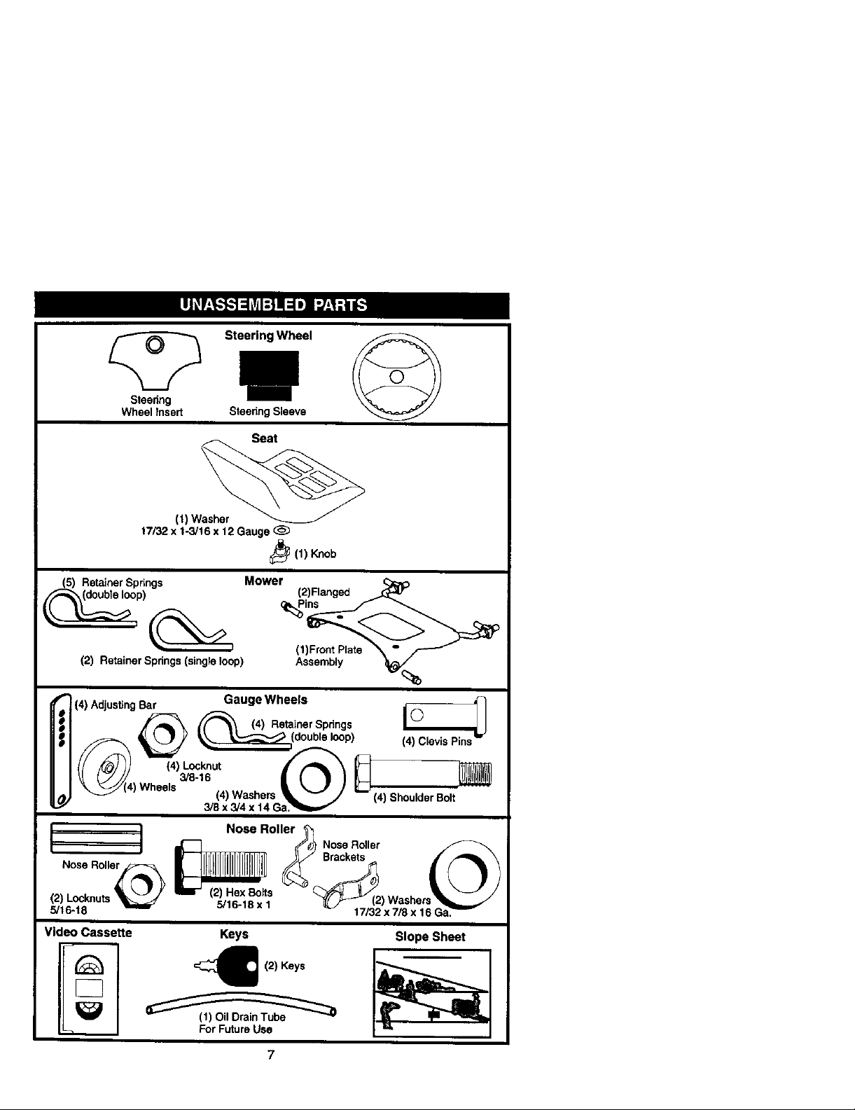
Steering Wheel
Steedng
Wheel Insert
(t) Washer
t7/32 x 1-3/16 x 12 Gauge (_
Steenng Sleeve
Seat
_(1) Knob
(5) Retainer Spdngs Mower
(2) Retainer Springs (single loop)
(2) Ranged
(1)Front Plate
Assembly
%
(4) Adjusting Bar IIC'_ _
_('_) eels (4) Washers _,_..../// L--_(4) Shoulder Bolt
I / Nose Roller_
I Nose Roll/e_ L"] _ Nose Roller__ _ Brackets , ...,_L \
(2) Losknuts _ _tt_.I. t "_( _ (2) Washers
5/16-18 ..... x. _ 17/32 x 7/8 x 16 Ga._
Video Cassette Keys
Gauge Wheels
_ (4)R_inerSp_ogs ©
3/8 x 3/4 x 14 Ga?_m,,,, _
Slope Sheet
_ (2) Keys
For Future Use
Yournewtractorhasbeenassembledatthefactorywithexceptionofthosepartsleft
unassembled for shipping purposes. To ensure safe and proper operation of your
tractor all parts and hardware you assemble must be tightened securely. Use the
correcttools as necessary to insure proper tightness. Review the video cassette before
you begin.
TOOLS REQUIRED FOR ASSEMBLY
A socket wrench set will make assembly
easier, Standard wrench sizes you need
are listed below,
(2) 9/16" wrench (1) 3/4" Socket w/
(1) 1/2" wrench drive ratchet
(1) Utilityknife (1) Pliers
(1) Tire pressure gauge
When rightor lefthand is mentioned in
this manual, it means, fromyour point of
view,when you are in the operating
position (seated behind the steering
wheel).
TO REMOVETRACTOR FROM
CARTON
UNPACK CARTON
1. Remove all accessible loose parts
and parts cartons from carton.
2. Cut, from top to bottom, along lines on
all four corners of carton, and lay
panels flat.
3. Remove mower and packing materi-
als.
4. Check for any additional loose parts
or cartons and remove.
BEFORE REMOVINGTRACTOR
FROM SKID
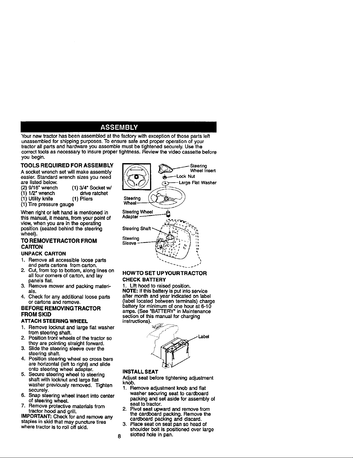
ATTACH STEERING WHEEL
1, Remove Iocknut and large flat washer
from steering shaft.
2. Positionfront wheels ofthe tractor so
they are pointing straight forward.
3, Slide the steering sleeve over the
steering shaft,
4. Positionsteering wheel so cross bars
are horizontal (left to right) and slide
onto steering wheel adapter.
5. Secure steering wheel to steering
shaft with lecknut and large flat
washer previously removed. Tighten
securely.
6. Snap steering wheel insert into center
of steering wheel.
7. Remove protective materials from
tractor hood and grill.
IMPORTANT: Check for and remove any
staples in skid that may puncture tires
where tractor is to roll off skid,
I//_--_\1 l_=d=T WheelInsert
I( _70_ )1 _---Lo_ Nut
_ l_ga RatWasher
Steering / _._ _J)
SteeringWheel
Adapter_ =P
Steering s
Sleev
HOWTO SET UPYOURTRACTOR
CHECK BATTERY
1. Lifthood to raised position.
NOTE: If thisbattery is putintoservice
after month and year indicated on label
blabellocated between terminals) charge
artery for minimum of one hour at 6-10
amps. (See 'BATTERY" in Maintenance
section of this manual for charging
instructions).
INSTALL SEAT
Adjust seat before tighteningadjustment
knob.
1. Remove adjustment knob and flat
washer securing seat to cardboard
packing and set aside for assembly of
seat to tractor.
2. Pivotseat upward and remove from
the cardboard packing. Remove the
cardboard packing and discard.
3. Place seat on seat pan so head of
shoulder bolt is positioned over large
8 slotted hole in pan.
_'_ _.....--_ Steedng
4. Pushdown on seat to engage
shoulder bolt in slot and pull seat
towards rear oftractor.
5. Pivot seat and pan forward and
assemble adjustment knob and flat
washer loosely. Do not tighten.
6. Lower seat into operating position and
sit in seat.
7. Slide seat until a comfortable position
is reached which allows you to press
clutch/brake pedal all the way down.
8. Get off seat without moving its
adjusted position.
9. Raise seat and tighten adjustment
knob securely.
NOTE: You may now rollor drive your
tractor off the skid. Followthe appropriate
instructionbelow to remove the tractor
from the skid,
TO ROLLTRACTOR OFF SKID (See
Operation section for location and
function of controls)
1. Press lift lever plunger and raise
attachment lift lever to its highest
position.
2. Release parking brake by depressing
brake pedal.
3. Place freewheel control in freewheel-
ing position to disengage transmis-
sion(See "TO TRANSPORT" inthe
Operation section of this manual).
4. Roll tractor forward off skid.
TO DRIVETRACTOR OFF SKID (See
Operation section for location and
function of controls)
_, WARNING: Before starting, read,
understand and follow all instructionsin
the Operation section of this manual. Be
sure tractor is in a well-ventilated area. Be
sure the area in front of tractor is clear of
other people and objects.
Seat
Shoulder
Bolt
t. Be sure all the above assembly steps
have been completad.
2. Check engine oil level and fill fuel
tank with gasoline.
3. Place freewheel control in "transmis-
sion engaged" position.
4. Sit on seat in operating position,
depress brake pedal and set the
parking brake.
5. Press lift lever plunger and raise
attachment lift lever to its highest
position.
6. Start the engine. After engine has
started, move throttle control to idle
position.
7. Release parking brake.
8. Slowly depress forward drive pedal
and drive tractor off skid.
9. Apply brake to stop tractor and set
parking brake.
10.Turn ignition key to "OFF" position.
Continue with the instructions that follow.
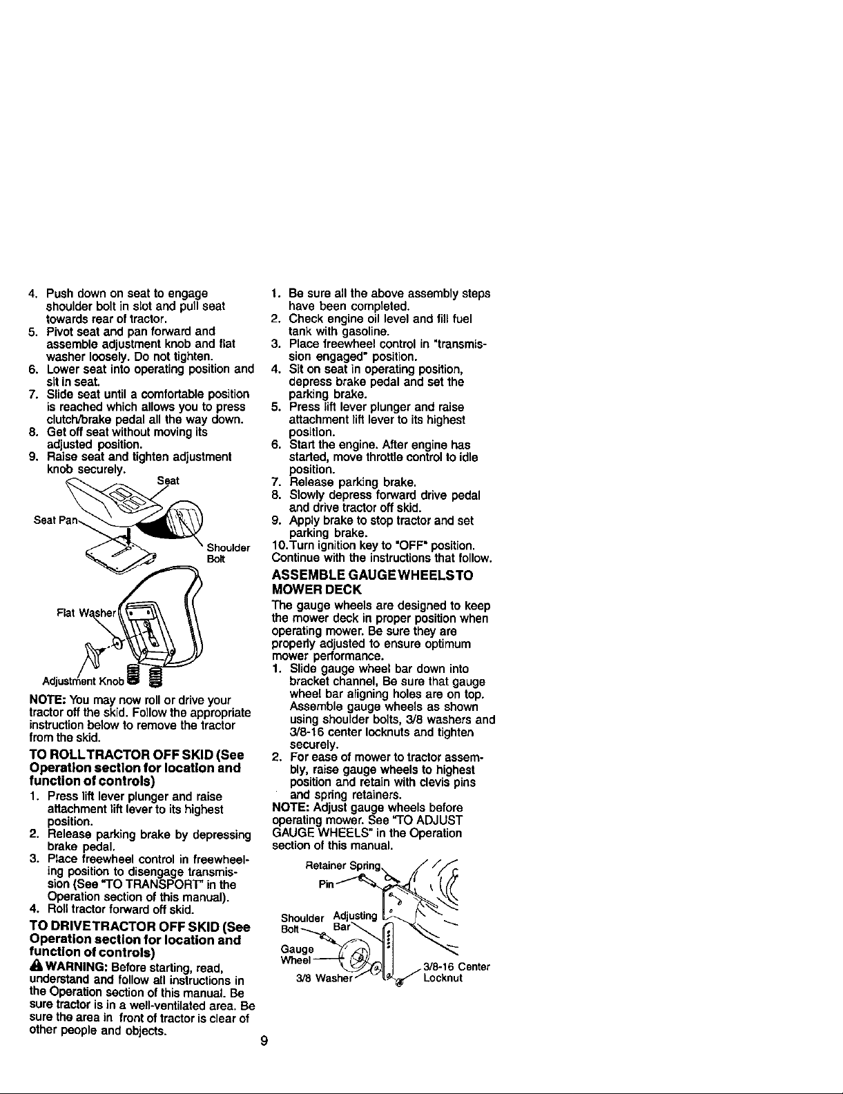
ASSEMBLE GAUGEWHEELSTO
MOWER DECK
The gauge wheels are designed to keep
the mower deck in proper position when
operating mower. Be sure they are
properly adjusted to ensure optimum
mower performance.
1. Slide gauge wheel bar down into
bracket channel, Be sure that gauge
wheel bar aligning holes are on top.
Assemble gauge wheels as shown
using shoulder bolts, 3/8 washers and
3/8-16 center Iocknuts and tighten
securely.
2. For ease of mower to tractor assem-
bly, raise gauge wheels to highest
position and retain with clevis pins
and spdng retainers.
NOTE: Adjust gauge wheels before
operating mower. See "TO ADJUST
GAUGE WHEELS" in the Operation
section of this manual.
Retainer
Pin_
Shoulder
Gauge
3/8-16
9

TO AI-rACH NOSE ROLLER
1. Positionbrackets, 17/32 x 7/8 x 16
gauge washers, and nose miler
between deck mounting brackets as
shown. Be sure to position brackets
on correct side, as shown.
2. Install hex bolts and lock nuts as
shown. Tighten hardware securely.
NOTE: Be sure bracket tabs are posi-
tioned in tab holes in deck brackets.
Tab Nose Roller
Lock
"B" Bracket
Hax Bol
Bracket
INSTALL MOWER AND DRIVE BELT
Be suretractoris on leve_surface and mower
suspensionarmsare raisedwithattachn_wt
liftcontrol.Engageparkingbrake.
1. Cut and remove ties securing anti-
sway bar and belts. Swing anti-sway
bar to left side of mower deck.
2. Slide mower under tractor with
deflector shield to right side of tractor.
IMPORTANT: Check belt for proper
routingin all mower pulley grooves.
3. If equipped, turn height adjustment
knob countemlockwise until it stops.
4. Lower mower linkage with attachment
lift control.
5. Be sure belt tension rod is in disen-
gaged position. Lock
Belt Tension Rod
Disengaged
ChassLs Brackat_
Gauge
6. Install belt into electric clutchpulley
groove.
7. Place the suspension arms on
outward pointing dock pins. Retain
with double loop retainer spr_ngwith
loops up as shown.
8. Install front plate assembly to tractor
suspension brackets and retain with
single loop retainer springs as shown.
9. Position front plate assembly between
front mower brackets. Raise deck and
plate assembly to align holes and
insertflanged pins. Secure pins with
double loop retainer springs between
the plate assembly and mower
brackets.
NOTE: To assist in locating hole in
flanged pin, the hole in pin is inUne with
notchon head of pin. If necessary, move
mower side-to-side to give space
between plate and mower brackets.
IMPORTANT: Chock belt for proper
routingin all mower pulley grooves.
10. Engage belt tension rod by pushing
rod into locking bracket.
_kCAUTION: Belt tension rodis spring
loaded. Have a tight grip on rod and
engage slowly.
11.Connect anti-sway bar to chassis
bracket under left footrest and retain
with double loop retainer spring.
12.If equipped, turn height adjustment
knob clockwiseto remove slack from
mower suspension.
13. Raise deck to highest position.
14.Adjust gauge wheels before operating
mower as shown in the Operation
section ot this manual.
Electdc Clutch
Pulley Front Suspension Brackets
Front Front Plate Assembly
Mower _Doubla Loop
Bracket Retainer Springs
Double Loop
Retainer Spnng
Anti-Sway
USEPLIERSFOR
RETAJNERSPRINGSSuspension Arms
Spring (Outward
Double Loop Retainer
Up pointing deck pins)
10
Single
Loop
Retainer
Springs
Shield
CHECKTIRE PRESSURE
The tires on yourtractor were overinflated
at the factory for shippingpurposes.
Correct tire pressure is important for best
cutting performance.
• Reduce tire pressure to PSI shown in
"PRODUCT SPECIFICATIONS" section
ofthis manual.
CHECK DECK LEVELNESS
For best cutting results, mower housing
should be properly leveled. See "TO
LEVEL MOWER HOUSING" in the
Service and Adjustments section of this
manual,
CHECK FOR PROPER POSITION OF
ALL BELTS
See the figuresthat are shownfor
replacing motion and mower blade drive
belts in the Service and Adjustments
section of this manual. Verify that the
belts are routedcorrectly.
CHECK BRAKE SYSTEM
After you team how to operate your
tractor,check to see that the brake is
propedyadjusted. See "TO ADJUST
BRAKE" in the Service and Adjustments
section of this manual.
V"CHECKLIST
BEFORE YOU OPERATE AND ENJOY
YOUR NEW TRACTOR, WE WISH TO
ASSURE THAT YOU RECEIVE THE BEST
PERFORMANCE AND SATISFACTION
FROM THIS QUALITY PRODUCT.
PLEASE REVIEWTHE FOLLOWING
CHECKLIST:
/ All assembly instructions have been
completed.
,/No remaining loose parts in carton.
,/Battery is propedy prepared and
charged. (Minimum 1 hour at 6 amps).
,/Seat is adjusted comfortably and
tightened securely.
,/All tires are propedy inflated. (For
shipping purposes, the tires were
ovednflated at the factory).
4 Be sure mower deck is properly leveled
side-to-side/front-to-rear for best cutting
results. (Tires must be propedy inflated
for leveling).
/ Check mower and drive belts. Be sure
they are routed propedy around pulleys
and inside all belt keepers.
/ Check wiring. See that all connections
are still secure and wires are properly
clamped.
,/Before drivingtractor, be sure free-
wheel control is in drive position.
WHILE LEARNING HOW TO USEYOUR
TRACTOR, PAY EXTRA A'I-]'ENTION TO
THE FOLLOWING IMPORTANT ITEMS:
,," Engine oil is at proper level.
/ Fuel tank is filled with fresh, clean,
regular unleaded gasoline.
,/Become familiar with all controls - their
location and function. Operate them
before you start the engine.
,/Be sure brake system is in safe
operating condition.
/ It is importantto purge the transmission
before operating your tractor for the first
time. Followproper starting and
transmission purging instructions(See
"TO START ENGINE" and "PURGE
TRANSMISSION" in the Operation
section of this manual).
11
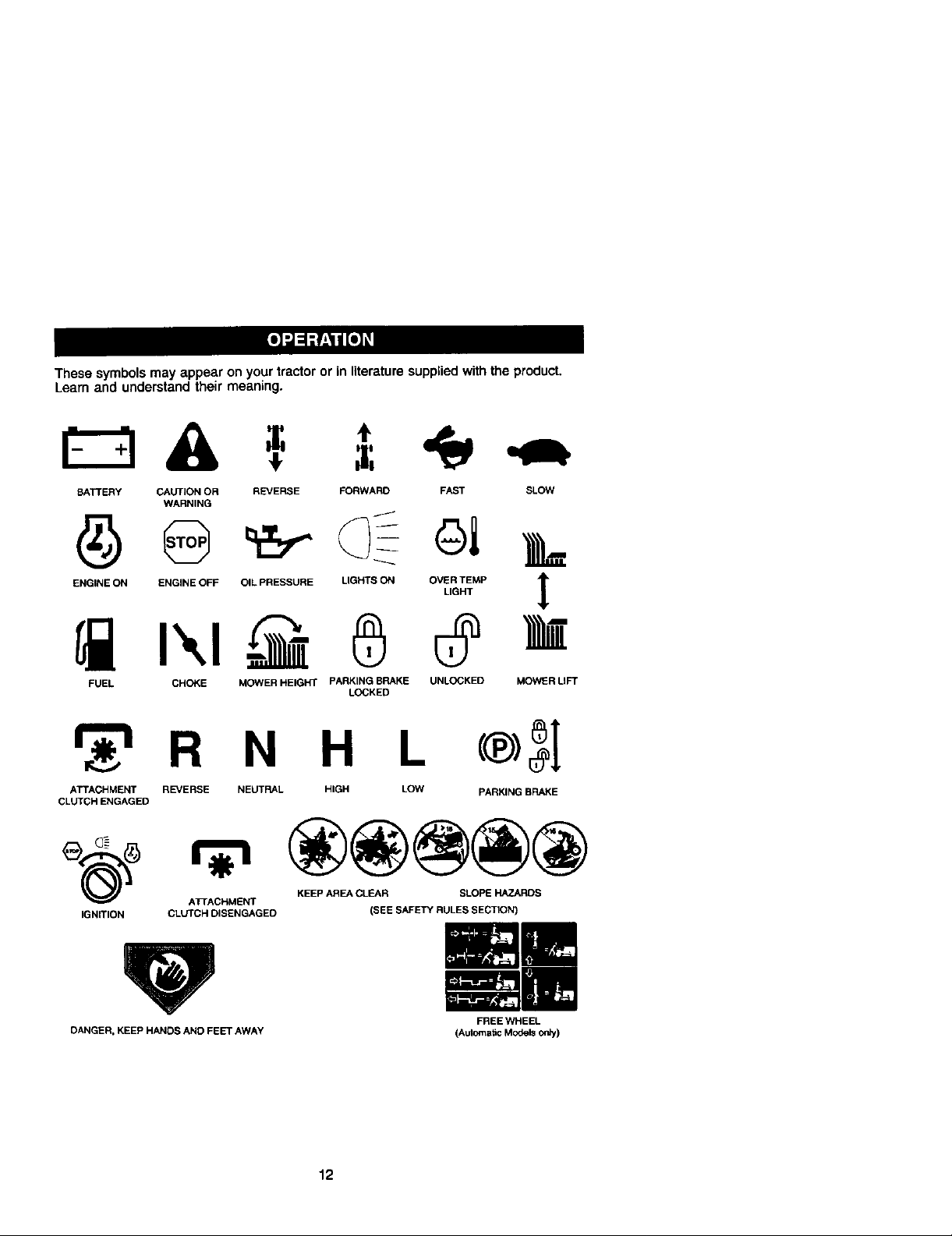
These symbols may appear on your tractor or in literature supplied with the product.
Learn and understand their meaning.
BATTERY CAUTION OR REVERSE FORWARD FAST SLOW
WARNING
E.O,NEO.ENO,NEOEFO.LPRESSOREUaHTSO.O_E_P |
FUEL CHOKE MOWER HEIGHT PARKING BRAKE UNLOCKED MOWER LIFT
LOCKED
r 'l R N H L
ATTACHMENT REVERSE NEUTRAL HIGH LOW PARKING BRAKE
CLUTCH ENGAGED
IGNITION CLUTCH DISENGAGED (SEE SAFETY RULES SECTION)
ATrACHMENT
KEEP AREA CLEAR SLOPE HAZARDS
4"
DANGER, KEEP HANDS AND FEET AWAY
FREE WHEEL
(Automatic Modelsonly)
12

KNOWYOURTRACTOR
READ THIS OWNER'S MANUAL AND SAFETY RULES BEFORE OPERATING
YOUR TRACTOR
Compare the illustrationswith your tractor to familiarize yourself with the locations of
various controlsand adjustments. Save this manual for future reference.
Hourmeter LLghtSwitch Position
Ignition Attachment Clutch Switch
Ammeter
Switch
Drive Pedal
Plunger
Attachment Lift Lever
Reverse Drive Pedal
Adjustment
Freewheel
Our tractors conformto the safety standards of the American
National Standards Institute.
A'I'rACHMENT CLUTCH SWITCH: Used
to engage the mower blades, or other
attachments mounted to your tractor.
LIGHT SWITCH: Turnsthe headlightson
and off.
THRO'I-I'LE CONTROL - Used to control
engine speed.
CHOKE CONTROL - Used when starting
a cold engine.
BRAKE PEDAL: Used for brakingthe
tractor and starting the engine.
FREEWHEEL CONTROL: Disengages
transmission for pushing or slowly towing
the tractor with the engine off.
ATTACHMENT LIFT LEVER: Used to
raise, lower and adjust the mower deck
or other attachments mounted to your
tractor.
Brake
Lever
LIFT LEVER PLUNGER: Usedto release
attachment liftlever when changing its
position.
IGNITION SWITCH: Used for startingand
stopping the engine.
AMMETER: Indicates battery charging (+)
or discharging (-).
PARKING BRAKE: Locks clutch/brake
into the brake position.
FORWARD DRIVE PEDAL - Used for
forward movement of tractor.
REVERSE DRIVE PEDAL- Used for
reverse movement of tractor.
CRUISE CONTROL LEVER - Used to set
forward movement of tractor at desired
speed without holdingthe forward drive
pedal.
HOURMETER - Indicates hours of
operation.
13
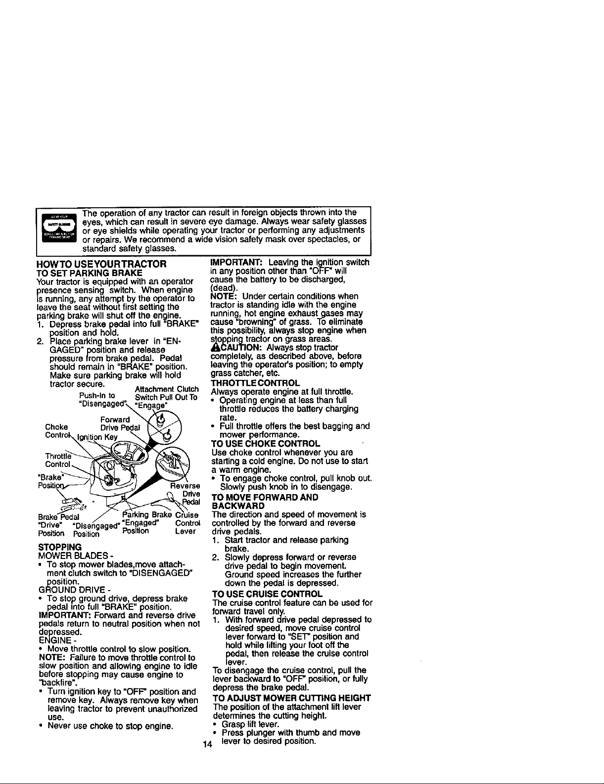
The operation of any tractor can result in foreign objects thrown into the I
eyes, which can resultin severe eye damage. Always wear safety glasses
or eye shields while operating your tractor or performing any adjustments
or repairs. We recommend a wide vision safety mask over spectacles, or
standard safety glasses. I
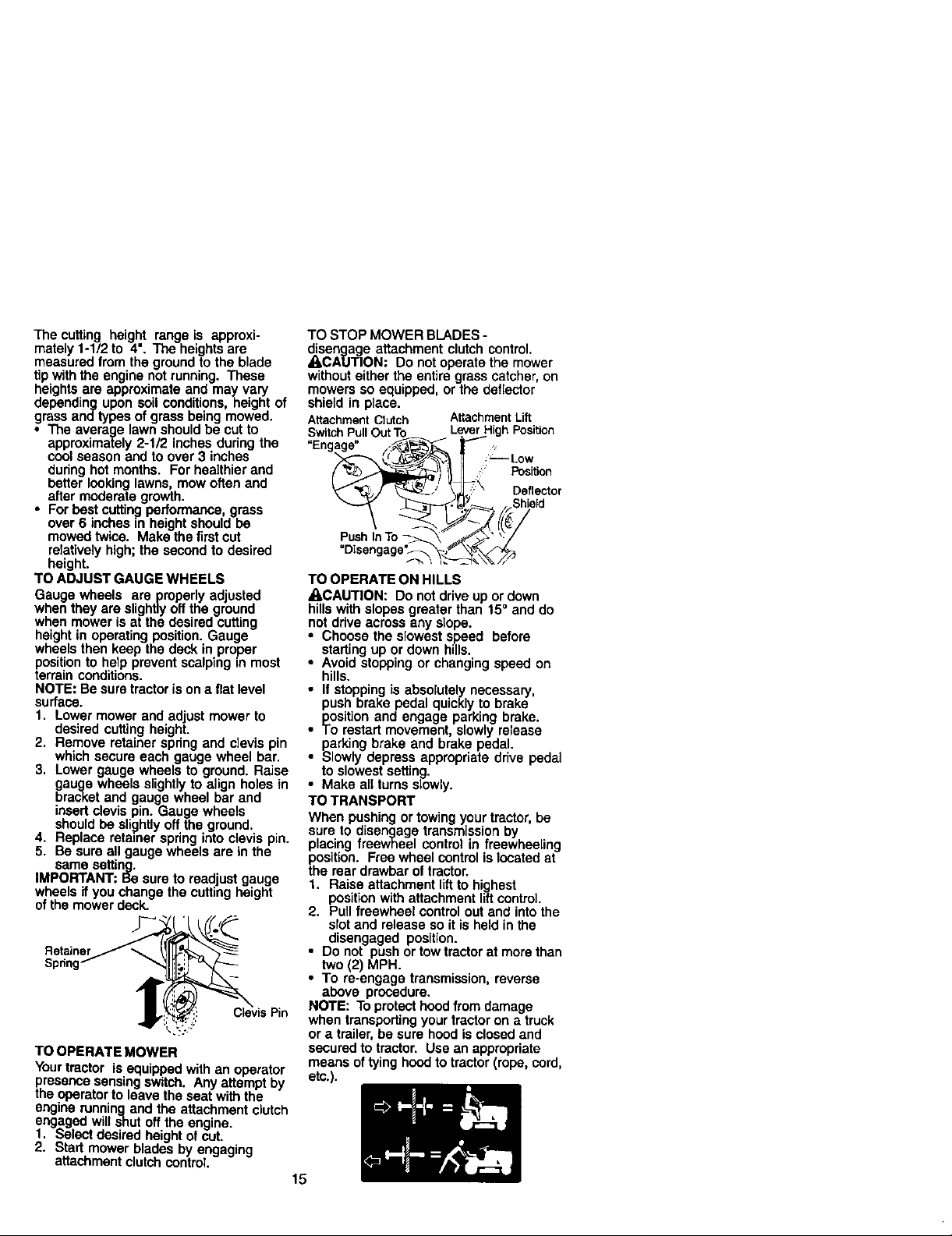
HOWTO USEYOURTRACTOR
TO SET PARKING BRAKE
Your tractor is equipped with an operator
presence sensing switch. When engine
is running,any attempt by the operator to
leave the seat without first setting the
parking brake will shut offthe engine.
1. Depress brake pedal into full "BRAKE"
position and hold.
2. Place parking brake lever in "EN-
GAGED" position and release
pressure from brake pedal. Pedal
should remain in "BRAKE" .Ro.sition.
Make sure parking brake wdlhold
tractor secure.
Push-into SwitchPullOutTo
"Disengaged"_ngag_._
Choke DrivePedal I_"-._ , )
Forward _ t_ _A
AttachmentClutch
con,ro
c or r iT
"Brake"_"'_ j_
Dr've Disengaged ..
Position Position Position Lever
STOPPING
MOWER BLADES -
• To stop mower blades,move attach-
merit clutchswitch to "DISENGAGED"
position.
GROUND DRIVE -
• To stop ground drive, depress brake
pedal into full "BRAKE" position.
IMPORTANT: Forward and reverse drive
pedsls return to neutral positionwhen not
depressed.
ENGINE -
• Move throttle controlto slow position.
NOTE: Failure to move throttle control to
slow positionand allowing engine to idle
before stopping may cause engine to
"backfire_.
• Turn ignition key to =OFF' position and
remove key. Always remove key when
leaving tractor to prevent unauthorized
use.
• Never use choke to stop engine.
IMPORTANT: Leaving the ignitionswitch
in any position other than "OFF" will
cause the battery to be discharged,
(dead).
NOTE: Under certainconditions when
tractor is standing idlewith the engine
running, hot engine exhaust gases may
cause"browning" of grass. To eliminate
this possibility, always stop engine when
_(_ping tractor on grass areas.
AUTION: Always stop tractor
completely, as described above, before
leawng the operator's position; to empty
grass catcher, etc.
THROTrLE CONTROL
Always operate engine at full throttle.
• Operating engine at lessthan full
throttle reduces the battery charging
rate.
• Fullthrottleoffers the best bagging and
mower performance.
TO USE CHOKE CONTROL
Use choke control whenever you are
starting a cold engine. Do not use to start
a warm engine.
• To engage choke control, pullknob out.
Slowly push knob in to disengage.
TO MOVE FORWARD AND
BACKWARD
The direction and speed of movementis
controlledby the forward and reverse
drive pedals.
1. Start tractor and release parking
brake.
2. Slowly depress forwardor reverse
drive pedal to begin movement.
Ground speed increases the further
down the pedal is depressed.
TO USE CRUISE CONTROL
The cruise controlfeature can be used for
forward travel only.
1. With forward drive pedal depressed to
desired speed, move cruise control
lever forward to "SET" positionend
holdwhile liftingyour foot off the
e_veal,then release the cruise control
r.
To disengage the cruisecontrot, pull the
lever backward to "OFF" position, or fully
depress the brake pedal
TO ADJUST MOWER CUTTING HEIGHT
The position of the attachment liftlever
determines the cutting height.
• Grasp liftlever.
Press plungerwith thumband move
14° lever to desired position.
Thecuttingheightrangeisapproxi-
mately 1-1/2to 4". The heights are
measured from the ground to the blade
tipwith the engine not running. These
heights are approximate and may vary
depending upon soil conditions, height of
grass andtypes of grass being mowed.
• The average lawn should be cut to
approximately 2-1/2 inches during the
coolseason and to over 3 inches
dudng hot months• For healthier and
better looking lawns, mow often and
after moderate growth.
• For best cutting performance, grass
over 6 inches _nheight sheutd he
mowed twice. Make the firstcut
relatively high;the second to desired
height.
TO ADJUST GAUGE WHEELS
Gauge wheels are properly adjusted
when they are slightly off the ground
when mower is at the desired cutting
height in operating position. Gauge
wheels then keep the deck in proper
positionto help prevent scalping m most
terrain conditions.
NOTE: Be sure tractor is on a flat level
surface.
1. Lower mower and adjust mower to
desired cutting height•
2. Remove retainer spring and clevis pin
which secure each gauge wheel bar.
3. Lower gauge wheels to ground. Raise
gauge wheels slightlyto align holes in
bracket and gauge wheel bar and
insert clevis pin. Gauge wheels
Replace retainer springinto clevis pin.
. should be slightly off the ground•
• Be sure all gauge wheels are in the
same setting.
IMPORTANT: Be sure to readjust gauge
wheels if you change the cutting height
ofthe mower deck.
Retainer
Sprint
TO OPERATE MOWER
Your tractor is equipped with an operator
presence sensing switch. Any attempt by
the operator to leave the seat with the
engine runningand the attachment clutch
engaged will shut off the engine•
1. Select desired height of cut.
2. Start mower blades by engaging
attachment clutchcontrol.
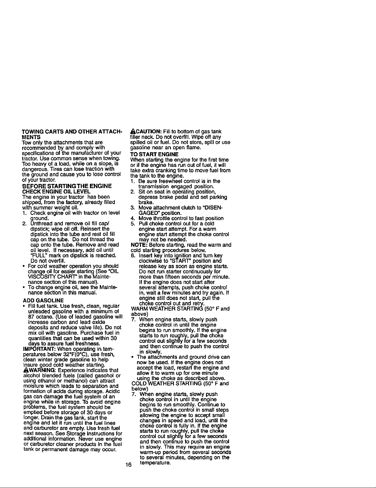
TO STOP MOWER BLADES -
disengage attachment clutch control.
_,CAUTION: Do not operate the mower
without either the entire grass catcher, on
mowers so equipped, or the deflector
shield in place.
AttachmentClutch AttachmentLift
SwitchPullOutTo LeverHighPosition
"Engage" /_ r- ?
_,,_ _/ \_\ Deflector
PushInTo _ L_" ":/
TO OPERATE ON HILLS
ACAUTION: DO notdrive up or down
hills with slopes greater than 15° and do
not ddve across any slope.
• Choose the slowest s_eed before
• stading up or down h=lls.
Avoid stopping or changing speed on
hills.
push brake pedal quickly to brake
position and engage parking brake.
To restart movement, slowly release
parking brake and brake pedal.
ll stopping is absolutely necessary,
Slowly depress appropriate drive pedal
to slowest setting.
Make all turns slowly.
TO TRANSPORT
When pushing or towing your tractor, be
sure to disengage transmission by
placing freewheel control in freewheeling
position. Free wheel control is located at
the rear drawbar of tractor.
1. Raise attachment liftto highest
position with attachment liltcontrol.
2. Pull freewheel control out end into the
slot and release so it is held in the
disengaged position.
• Do not push or towtractor at morethan
two (2) MPH.
• To re-engsgo transmission, reverse
above procedure.
NOTE: To protect hood from damage
when transporting your tractor on a truck
or a trailer, be sure hood is closed and
secured to tractor. Use an appropriate
means of tying hood to tractor (rope, cord,
etc.).
15
TOWINGCARTSANDOTHERATrACH-
MENTS
Towonlytheattachmentsthatare
recommendedbyandcomplywith
specificationsofthemanufacturer of your
tractor.Use common sense when towing.
Too heavy of a load, while on a slope, is
dangerous. Tires can lose traction with
the ground and cause you to lose control
ofyourtractor.
BEFORE STARTINGTHE ENGINE
CHECK ENGINE OIL LEVEL
The engine in your tractor has been
shipped, from the factory, already filled
with summer weight oil.
1. Check engine oil with tractor on level
ground.
2. Unthraed and remove oil fillcap/
dipstick;wipe oil off. Reinsert the
dipstick intothe tube and rest oil fill
cap on the tube. Do not thread the
cap ontothe tube. Remove and read
oil level. If necessary, add oiluntil
"FULL" mark on dipstick is reached.
Do not overfill.
• For cold weather operationyou should
change oil for easier starting(See =OIL
VISCOSITY CHART" in the Mainte-
nance section ofthis manual).
• To change engine oil, see the Mainte-
nance sectionin this manual.
ADD GASOLINE
• Fillfuel tank. Use fresh, clean, regular
unleaded gasoline with a minimum of
87 octane. (Use of leaded gasoline will
increase carbon and lead oxide
deposits and reduce valve life). Do not
mix oil with gasoline. Purchase fuel in
quantitiesthat can be used within 30
days to assure fuel freshness.
IMPORTANT: When operating in tem-
peratures below 32°F(0°C), use fresh,
clean winter grade gasoline to help
insure good cold weather starting.
_,WARNING: Experience indicates that
alcohol blended fuels (called gasohol or
using ethanol or methanol) can attract
moisture which leads to separation and
formation of acids during storage. Acidic
gas can damage the fuel system of an
engine while in storage. To avoid engine
problems, the fuel system should be
emptied before storage of 30 days or
longer. Drain the gas tank start the
engine and let it run until the fuel lines
and carburetor are empty. Use fresh fuel
next season. See Storage Instructions for
additional information. Never use engine
or carburetor cleaner products in the fuel
tank or permanent damage may occur.
A,CAUTION: Fill to bottom of gas tank
filler neck. Do not overfill.Wipe offany
spilled oil or fuel. Do not store, spillor use
gasoline near an open flame.
TO START ENGINE
When startingthe engine forthe firsttime
or if the engine has run outof fuel, it will
take extra cranking time to move fuel from
the tank to the engine.
1. Be sure freewheel control is in the
transmission engaged position.
2. Sit on seat in operating position,
depress brake pedal and set parking
brake.
3. Move attachment clutch to "DISEN-
GAGED" position.
4. Move throttlecontrolto fast position
5. Pull choke control out for a cold
engine start attempt. For a warm
engine startattempt the choke control
may not be needed.
NOTE: Before starting,read the warm and
cold starting procedures below.
6. Insert key into ignitionand turn key
clockwise to =START" position and
release key as soonas engine starts.
Do not run starter continuouslyfor
more than fifteen seconds per minute.
If the engine does not start after
several attempts, push choke control
in, wait a few minutes and try again. If
engine still does not start, pull the
choke control out and retry.
WARM WEATHER STARTING (50° F and
above)
7, When engine starts, slowly push
choke control in until the engine
begins to run smoothly. Ifthe engine
starts to run roughly, pull the choke
control out slightly for a few seconds
and then continue to push the control
in slowly.
• The attachments and ground drive can
now be used. If the engine does not
accept the load, restart the engine and
allow it to warm up for one minute
using the choke as described above.
COLDWEATHER STARTING (50 = F and
below)
7. When engine starts, slowlypush
choke control in untilthe engine
begins to run smoothly. Continue to
push the choke control in small steps
allowing the engine to accept small
changes in speed and load, until the
choke control isfully in. Ifthe engine
startsto run roughly,pull the choke
control out slightlyfor a few seconds
and then continueto push the control
in slowly. This may require an engine
warm-up peded from several seconds
to several minutes, depending on the
16 temperature.
AUTOMATICTRANSMISSIONWARM UP
Before driving the unit in cold weather,
the transmission should be warmed up as
follows:
1. Be sure the tractor is on level ground.
2. Release the parking brake and let the
brake slowly return to operating
position.
3. Allow one minute for transmission to
warm up. This can be done during the
engine warm up period.
• The attachments can be used during
the en_line warm-up period after the
transmtssion has been warmed up and
may require the choke control be
pulled out slightly.
NOTE: If at a high altitude (above 3000
feet) or in cold temperatures (below 32 F)
the carburetor fuel mixture may need to
be adjusted for best engine pedormance.
See "TO ADJUST CARBURETOR in the
Service and Adjustments section of this
manual.
PURGETRANSMISSlON
A,CAUTION: Never engage or disengage
freewheel lever while the engine is
running.
To ensure properoperationand pedor-
mance, itis recommended that the
transmissionbe purged before operating
tractorfor the firsttime. Thisprocadure will
removeany trapped air inside the trans-
mission which may have developed during
shippingof yourtractor.
IMPORTANT: Shouldyour transmission
require removal for serviceor replacement,
it shouldbe purged after reinstailation
beforeoperatingthe tractor.
1. Place tractor safely on level surface
with engine off and parking brake set.
2. Disengage transmission by placing
freewheel control in freewheeling
position(See "TO TRANSPORT" in
this section of manual).
3. Sittingin the tractor seat, start engine.
After the engine is running, move
throttlecontrol to slow position.
Disengage parking brake.
4. Depress forward drive pedal to full
forward position and hold for five (5)
seconds and release pedal. Depress
reverse ddve pedal to full reverse
positionand hold for five (5) seconds
and release pedal. Repeat this
procedure three (3) times.
NOTE: Dudng this procedurethere willbe
no movement of drivewheels. The airis
being removed from hydraulicddve
system.
5. Shut- oft engine and set parking
brake.
6. Engage transmission by placing
freewheel control in driving position
(See "TO TRANSPORT" in this section
of manual).
7. Sitting in the tractor seat, start engine.
After the engine is running, move
throttle control to half (1/2)speed.
Disengage parking brake.
8. Drive tractor forward for approximately
five feet then backwards for five feet.
Repeat this driving procedure three
times.
Your tractor is now purged and now ready
for normal operation.
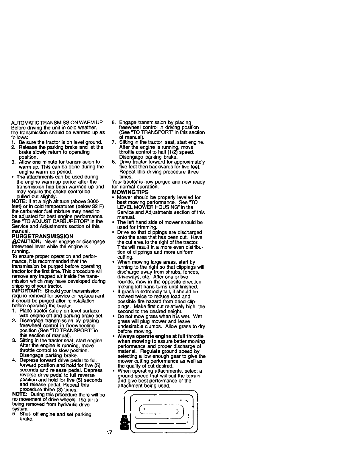
MOWINGTIPS
• Mower should be properly leveled for
best mowing performance. See "TO
LEVEL MOWER HOUSING" inthe
Service and Adjustments section ofthis
manual.
• The left hand side of mower should be
used for trimming,
• Ddve so that clippings are discharged
onto the area that has been cut. Have
the cut area to the right of the tractor.
This will result in a more even distribu-
tion of clippings and more uniform
cutting.
• When mowing large areas, start by
turning to the right so that clippings will
discharge away from shrubs, fences,
driveways, etc. After one or two
rounds, mow in the opposite direction
making left hand turns until finished.
• If grass is extremely tall, itshould be
mowed twice to reduce load and
possible fire hazard from dried clip-
pings. Make first cut relatively high; the
second to the desired height.
• Do not mow grasswhen it is wet. Wet
grass will plug mower and leave
undesirable clumps. Allow grass to dry
before mowing.
• Always operate engine at full throttle
when mowing to assure better mowing
performance and proper discharge of
matedai. Regulate ground speed by
selecting a low enough gear to give the
mower cuttingperformance as well as
the quality of cut desired.
• When operatingattachments, select a
ground speed that will suitthe terrain
and give best performance of the
attachment being used.
f
f
17
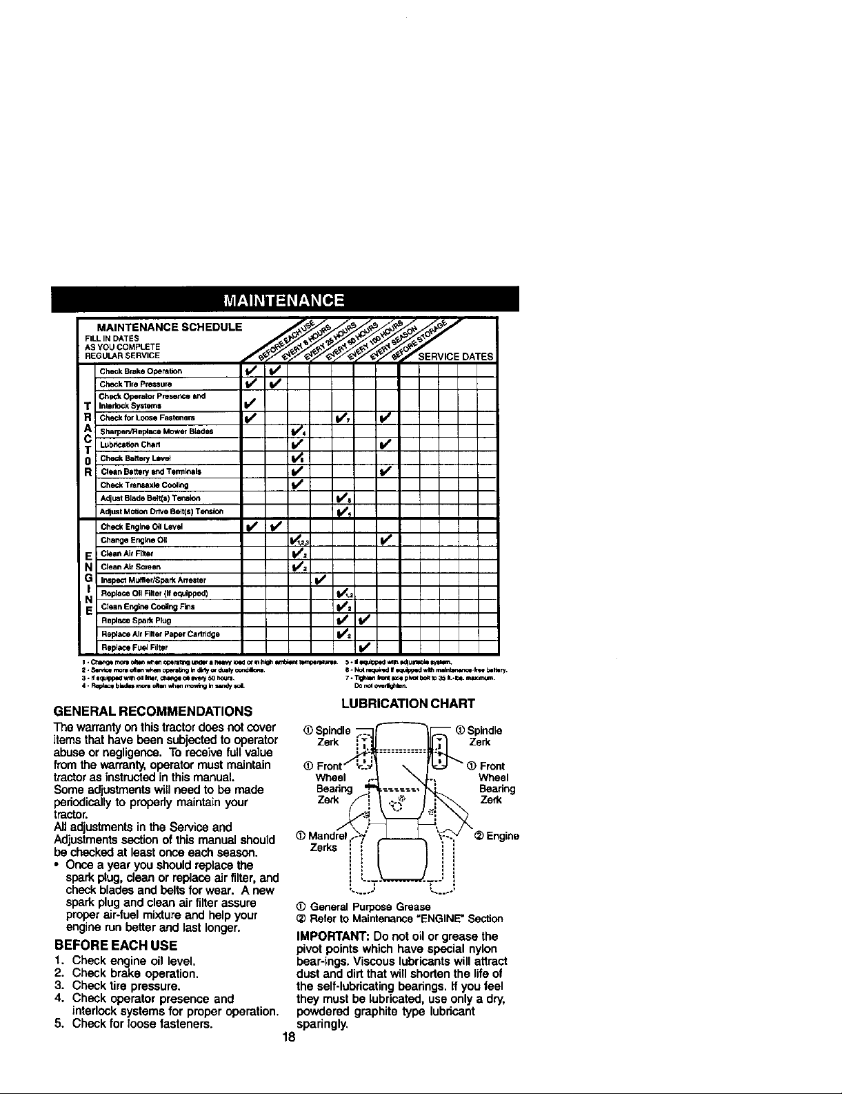
FILL IN DATES
M..°TO...CESC.EOOL
REGUL._R SERVICE RVICE DATES
Check Brake OperaSon _ f_
]Ch_k_,eP,.*u,e V' t/
Check Operator Preserlce and
T Interlock Systems t/e
R Chec_ f01"L0ose Fastenem (1_ (1_7 _e
Sharpen/R apiece Mower Blades 11_4
T Lub_n Chert _ _
R clean BatterywxlTermlnaa It/ I_/
Check Tr_ns_ae C_l_ _
AdjustBladeBelt(s)Tensk_ tt/s
AdjustMO_O_DriveBelt(s)Tensloe Ks
CheckEngineO_1Level _ b/
ChelaEr_o _l _i _
E Clean Ale Filet _=
N Clean ALrScreen 1_2
G Inspect M uffler/Spark Arre=t er I1_
Replece OII Filter (If equlpp4gd) _1,2
N Clean Englne Cooling F_s I_1
Rel_,ce AirRlter PaperCartddpe b/_
Rep4ace Fuel Niter _1_
I *Ct_r_i morn_ v,_i,, opemt;nour,d_-I hmvy loador lahigh_ent torr_peete.'o_ 5 - iio_r_k:_ed_1_ edlun_ sysm'_.
2. Ssrv_emor=dt Jn w_enccer_ir_ Indbly_-duzlyco,td_,tt. 6 - k_ mqt_nzdI/_quip_zdwl_ raa_-k_ bar.cry.
3. Ifiq_ed WtlhOllIg_ _,ge o_m*_y50 hours. 7. Tlgh_,flh_t _xl=pivotbo_tto35 ILJ_. m.lu(kn;_.
4 - Reel_=bk=_=rae_ oaoeW_,I movtbgInsanW_. DOr_ o,'erlk_mn.
GENERAL RECOMMENDATIONS
The warranty on this tractor does not cover
items that have been subjected to operator
LUBRICATION CHART
_) Spindle
Zerk Zerk
abuse or negligence. To receive full value
from the warranty,operator must maintain
tractoras instructedin this manual.
Some adjustmentswill need to be made
periodically to properly maintain your
Wheel
Bearing
Zerk
tractor.
All adjustments in the Service and
Adjustmentssection of this manual should
be checked at least once each season.
ZeUs
• Once a year you shouldreplace the
spark plug, clean or replace air filter, and
check bladesand belts for wear. A new
spark plugand clean air filter assure
proper air-fuel mixtureand help your
engine run better and last longer.
BEFORE EACH USE
1. Check engine oil level.
2. Check brake operation.
3. Check tire pressure.
4. Check operator presence and
interlock systems for proper operation.
5. Check for loose fasteners.
_)Gener_ Purpose Grease
_) Refer to Maintenance =ENGINE" Section
IMPORTANT: Do not oil or grease the
pivot points which have special nylon
bear-ings. Viscous lubricants will attract
dust and dirtthat will shortenthe life of
the self-lubricatingbearings. If you feel
they must be lubricated, use only a dry,
powdered graphite type lubricant
sparingly.
L.....= _.....,
18
Wheel
Bearing
Zerk
TRACTOR
Alwaysobservesafetyrules when
performing any maintenance.
BRAKE OPERATION
If tractor requires more than six (6) feet
stopping distance at high speed in
highestgear, then brake must be ad-
justed. (See "TO ADJUST BRAKE" inthe
Service and Adjustments section of this
manual).
TIRES
• Maintain proper air pressure in all tires
(See "PRODUCT SPECIFICATIONS"
section of this manual).
• Keep tires free of gasoline, oil, or insect
control chemicals which can harm
rubber.
• Avoidstumps, stones, deep ruts, sharp
objects and other hazards that may
cause tire damage.
NOTE: To seal tire punctures and prevent
flat tires due to slow leaks, tire sealant
may be purchased from your local parts
dealer. Tire sealant also preventstire dry
rot and corrosion.
OPERATOR PRESENCE SYSTEM
Be sure that operator presence and
interlock systems are working properly. If
your tractor does not function as de-
scribed below, repair the problem
immediately.
• The engine should not start unless the
brake pedal is fully depressed and
attachment clutch control is in the
disengaged position.
• When the engine is running, any
attempt bythe operatorto leave the
seat without first setting the parking
brake should shut off the engine.
• When the engine is running and the
attachment clutch is engaged, any
attempt bythe operator to leave the
seat should shut off the engine.
• The attachment clutch should never
operate unless the operator is in the
seat.
BLADE CARE
For best results mower blades must be
kept sharp. Replace bent or damaged
blades.
BLADE REMOVAL
1. Raise mower to highest position to
allow access to blades.
2. Remove hex bolt, lock washer and flat
washer securing blade.
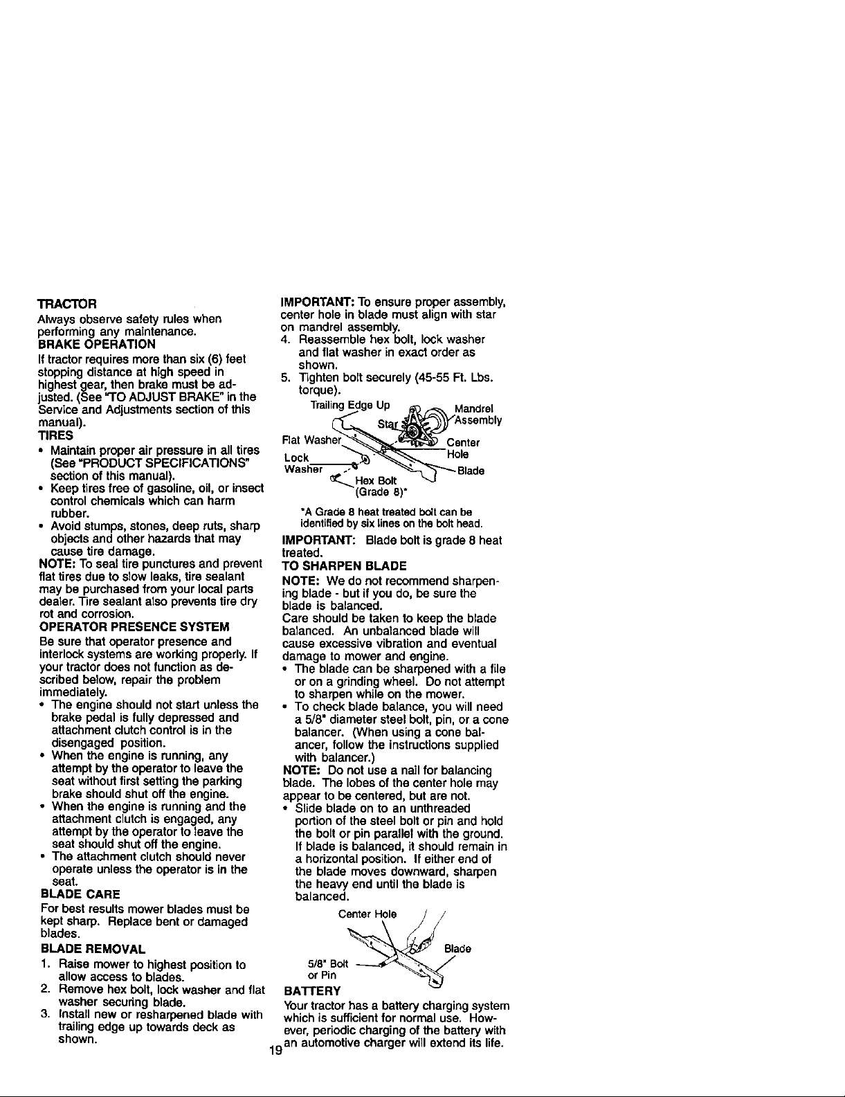
3. Install new or rasharpened blade with
trailingedge up towards deck as
shown.
IMPORTANT: To ensure proper assembly,
center hole in blade must align with star
on mandrel assembly.
4. Reassemble hex bolt, lock washer
and flat washer in exact order as
shown.
5. Tighten bolt securely (45-55 Ft. Lbs.
torque).
TrailingEdgeUp _:_ _ Mandrel
St_ '_ssembly
FlatWasher_--_,=._:_ Center
Lock "__Hols
Wash_ _"_-_"_1""_ Blade
(Grade8)
*AGrade 8heat treatedboltcanbe
identifiedby sixlineson thebolthead.
IMPORTANT: Blade bolt is grade 8 heat
treated.
TO SHARPEN BLADE
NOTE: We do not recommend sharpen-
ing blade - but if you do, be sure the
blade is balanced.
Care should be taken to keep the blade
balanced. An unbalanced blade will
cause excessive vibration and eventual
damage to mower and engine.
• The blade can be sharpened with a file
or on a grindingwheel. Do not attempt
to sharpen while on the mower.
• To check blade balance, you will need
a 5/8" diameter steel bolt, pin,or a cone
balancer. (When using a cone bal-
ancer, follow the instructions supplied
with belancar.)
NOTE: Do not use a nail for balancing
blade. The lobes of the center hole may
appear to be centered, but are not.
• Slide blade on to an unthreaded
portionof the steel boltor pin and hold
the bolt or pin parallet with the ground.
If blade is balanced, it should remain in
a horizontal position. If either end of
the blade moves downward, sharpen
the heavy end until the blade is
balanced.
Center Hole /
5/8"B_t
or Pin
BA'n'ERY
Yourtractor has a battery chargingsystem
which issufficient for normal use. How-
ever, periodic charging of the battery with
19 an automotive charger will extend its life.

• Keep battery and terminals clean.
• Keep battery bolts tight.
• Keep small vent holes open.
• Recharge at 6-10 amperes for 1 hour.
NOTE: The original equipment battery on
your tractor is maintenance free. Do not
attempt to open or remove caps or covers.
Adding or checking level of electrolyte is
not necessary.
TO CLEAN BA'I-I'ERY AND TERMINALS
Corrosion and dirt on the battery and
terminals can cause the battery to "leak"
power.
1. Remove terminal guard.
2. Disconnect BLACK battery cable first
then RED battery cable and remove
battery from tractor.
3. Rinse the battery with plain water and
dry.
4. Clean terminals and battery cable
ends with wire brush until bright.
5. Coat terminals with grease or petro-
leum jelly.
6. Reinstall battery (See "REPLACING
BA'F]'ERY" in the SERVICE AND
ADJUSTMENTS section of this
manual).
V-BELTS
Check V-belts for deterioration and wear
after 100 hours of operation and replace
if necessary.The belts are not adjustable.
Replace belts if they begin to slip from
wear,
TRANSAXLE COOLING
The transmission fan and coolingfins
should be kept clean to assure proper
cooling.
Do not attempt to clean fen or transmis-
sionwhile engine is running or while the
transmission is hot. To prevent possible
damage to seals, do not usa high
pressure water or steam to clean
transaxle.
• Inspect cooling fan to be sure fan
blades are intact and clean.
• Inspect cooling fins for dirt, grass
clippings and other matedals. To
prevent damage to seals, do not use
compressed air or high pressure
sprayer to clean cooling fins.
TRANSAXLE PUMP FLUID
The transaxle was sealed at the factory
and fluid maintenance is not required for
the life of the transsxle. Should the
transaxle ever leak or require servicing.
contact your nearest authorized service
center/department.
ENGINE
LUBRICATION
Only use high quality detergent oil rated
with API service classification SF-SJ.
Select the oiVsSAE visco,slty grade
according to your expected operating
Change the oilafter every 50 hours of
operation or at least once a year if the
tractor is not used for 50 hours in one
year.
Chock the crankcase oil level before
starting the engine and after each eight
(8) hours of operation. Tighten oil fill cap/
dipstick securely each time you chock the
oil level.
TO CHANGE ENGINE OIL
Determine temperature range expected
before oil change. All oil must meet API
service classificationSF-SJ.
• Be sure tractoris on level surface.
• Oil will drain more freely when warm.
• Catch oil in a suitable container.
1, Remove oil fill cap/dipsfick. Be careful
notto allow dirt to enter the engine
when changing oil
2, Remove cap from end ofdrain valve
and install the drain tube onto the
fitting.
3, Unlock drain valve by pushing inward
slightly and turning counterclockwise.
4. To open, pull out on the drain valve.
5. After oil has drained completely, close
and lock the drain valve by pushing
inward and turning clockwise untilthe
pin is in the locked position as shown.
6. Remove the drain tube and replace
the cap onto to the end ofthe drain
valve.
7. Refill engine with oil through oil fill
dipsticktube. Pour slowly. Do not
overfill. For approximate capacity see
"PRODUCT SPECIFICATIONS"
section of this manual.
8. Use gauge on oil fillcap/dipstick for
chocking level. Insed dipstick intothe
tube and rest the oil fill cap on the
tube. Do not thread the cap onto the
tube when taking reading. Keep oil
at "FULL" line on dipstick. Tighten cap
onto the tube securely when finished.
2O
 Loading...