

Craftsman 917272232 Owner’s Manual

Owner's Manual
iI:RRFTSMAN°I
20 HP
ELECTRIC START
48" MOWER
6 SPEED TRANSAXLE
LAWN TRACTOR
Model No.
917.272232
• Safety
• Assembly
• Operation
• Maintenance
• Repair Parts
CAUTION:
Read and fellow all
Safety Rules and Instructions
before operating this equip-
ment.
Sears, Roebuck and Co., Hoffman Estates, IL 60179
Visit our Ctaflsman website: wwwsears corn/craftsman
For answers to your questions
about this product, Call:
1-800-659-5917
Sears Craftsman Help Line
5 am - 5 pm, Mort - Sat

............................................... 2
Safety Rules ......................................... 3
Product Specifications .......................... 6
Assembly .............................................. 8
Operation ............................................ 13
Maintenance Schedule ...................... 19
Service and Adjustments .................... 23
Storage ............................................... 29
Troubleshooting ................................. 30
Repair Parts ........................................ 34
Parts Ordering ..................... Back Cover
19
LIMITED TWO YEAR WARRANTY ON CRAFTSMAN RIDING EQUIPMENT PARTS
For two (2) years from the date of purchase, if this Craftsman Riding Equipment is
maintained, lubricated and tuned up according to the instructions in the owner's
manual, Sears will repair or replace, free of charge, any parts found to be defective in
material or workmanship. Warranty service is available free of charge by returning your
Craftsman riding equipment to your nearest Sears Service Center. In-home warranty
service is available but a trip charge will apply. This warranty applies only while this
product is in the United States.
This Warranty does not cover:
• Expendable items which become worn during normal use, such as blades, spark
plugs, air cleaners, belts and oilfilters.
• Tire replacement or repair caused by punctures from outside objects, such as nails,
thorns, stumps, or glass.
• Repairs necessary because of operator abuse, including but not limitedto, damage
caused by towing objects beyond the capability of the riding equipment, impacting
objects that bend the frame or crankshaft, or over speeding the engine.
• Repairs necessary because of operator negligence, including but not limitedto,
electrical and mechanical damage caused by improper storage, failure to use the
proper grade and amount of engine oil, failure to keep the deck clear of flammable
debris, or the failure to maintain the equipment according to the instructions con-
tained in the owner's manual.
• Engine (fuel system) cleaning or repairs caused by fuel determined to be contami-
nated or oxidized (stale). In general, fuel should be used within thirty (30) days of its
purchase date.
• Riding equipment used for commercial or rental purposes. A product is =used for
commercial purpose" if is used for any purpose other than single family household
dwellings or in usage where profit is made.
LIMITED 90 DAY WARRANTY ON BATTERY
For ninety (90) days from date of purchase, if any battery included with this riding
equipment proves defective in material or workmanship and our testing determines the
batterywill not hold a charge, Sears will replace the battery at no charge. Warranty
service is available free of charge by returning your Craftsman dding equipmentto
your nearest Sears Service Center. In-home warranty service is available but a trip
charge will apply. This warranty applies only while this product is in the United States.
TO LOCATE THE NEAREST SEARS SERVICE CENTER OR TO SCHEDULE IN-HOME
WARRANTY SERVICE, SIMPLY CONTACT SEARS AT 1-800-4-MY-HOME
This Warranty gives you specific legal rights, and you may also have other rights which
may vary from state to state.
Sears, Roebuck and Co., D/817 WA, Hoffman Estates, IL 60179

|MPORTANT: This cuttk_gmachine is capable of amputating hands and feet and,
throwing objects. Failure to observe the following safety instructions could result m
seriousinjury or death.
I. GENERAL OPERATION
• Read, understand, and follow all
instructionsin the manual and on the
machine before starting,
• Only allow responsible adults, who are
familiar with the instructions,to operate
the machine.
• Clear the area of objects such as
rocks,toys wire etc., which could be
picked up and thrown by the bade.
• Be sure the area is clear of other
people before mowing. Stop machine
if anyone enters the area.
Never carry passengers.
Do notmow in reverse unless abso-
lutely necessary, Always look down
and behind before and while backing.
• Be aware of the mower discharge
directionand do not point it at anyone.
Do not operate the mower without
either the entire grass catcher or the
guard in place.
• Slow down before turning.
• Never leave a running machine
unattended. Always turn off blades, set
parking brake stop engine, and
remove keys before dismounting.
• Turn off blades when not mowing.
• Stop engine before removing grass
catcher or unclogging chute.
• Mow on|y in daylight or good artificial
light.
• Do not operate the machine while
under the ir_tuence ol alcohol or drags.
• Watch for traffic when operating near or
crossing roadways.
• Use extracarewhm'_loadingor
unloading the machine into a trailer or
truck.
• Data indicatesthat operators, ego 60
years and above, are involved in a
large percentage of riding mawer-
r_ated injuries. These operators
should evaluate their ability to operate
the ridingmower safely enough to
protect themselves and others from
serious injury.
• Keep machine free of grass, leaves or
other debris balld-up which can touch
hot exhaust / engine parts and bum.
Do not allow the mower deck to plow
leaves or other debds which can cause
build-upto occur. Clean any oilor fuel
spilla_]ebefore operating or storingthe
machine. Allow machine to cool before
storage.
11.SLOPE OPERATION
Slopes are a majorfactor related to less-of-
control and tipover accidents, which can
result in severe in ury or death. All slopes
require extra cauton. Ifyou cannot back up
the slope or if you feel uneasy on it, do not
mow it.
DO:
• Mow up and down slopes, not across.
• Remove obstacles such as rocks,tree
limbs, etc.
• Watch forholes, ruts, or bumps.
Uneven terrain could overturn the
machine. Tallgrass can hide ob-
stacles.
• Use slow speed. Choose a low gear
so that you will not have to stop or shift
while on the slope,
• Follow the manufacturer's recommen-
dationsfor wheel weights or counter-
weights to improvestability.
• Use extra care with grass catchers or
other attachments. These can change
the stability of the machine.
• Keep all movement on the slopes s/ow
and gradual. Do not make sudden
changes in speed or direction.
• Avoid starting or stopping on a _Jope. If
tires lose traction, disengage the
blades and proceed slowly straight
down the slope.
DO NOT:
• Do not turn on slopes unless neceso
sary, and then, turn slowly am:l gradu-
ally downhill, if possible.
• Do not mow near drop-offs, ditches, or
embankments. The mower could
suddenly turn over if a whee_ is over
the edge of a cliff or ditch, or if an edge
caves in.
• Do not mow on wet grass. Reduced
traction could cause sliding.
• Do not try to stabilizethe machine by
putting your foot on the ground,
• Do not use grass catcher on steep
slopes.
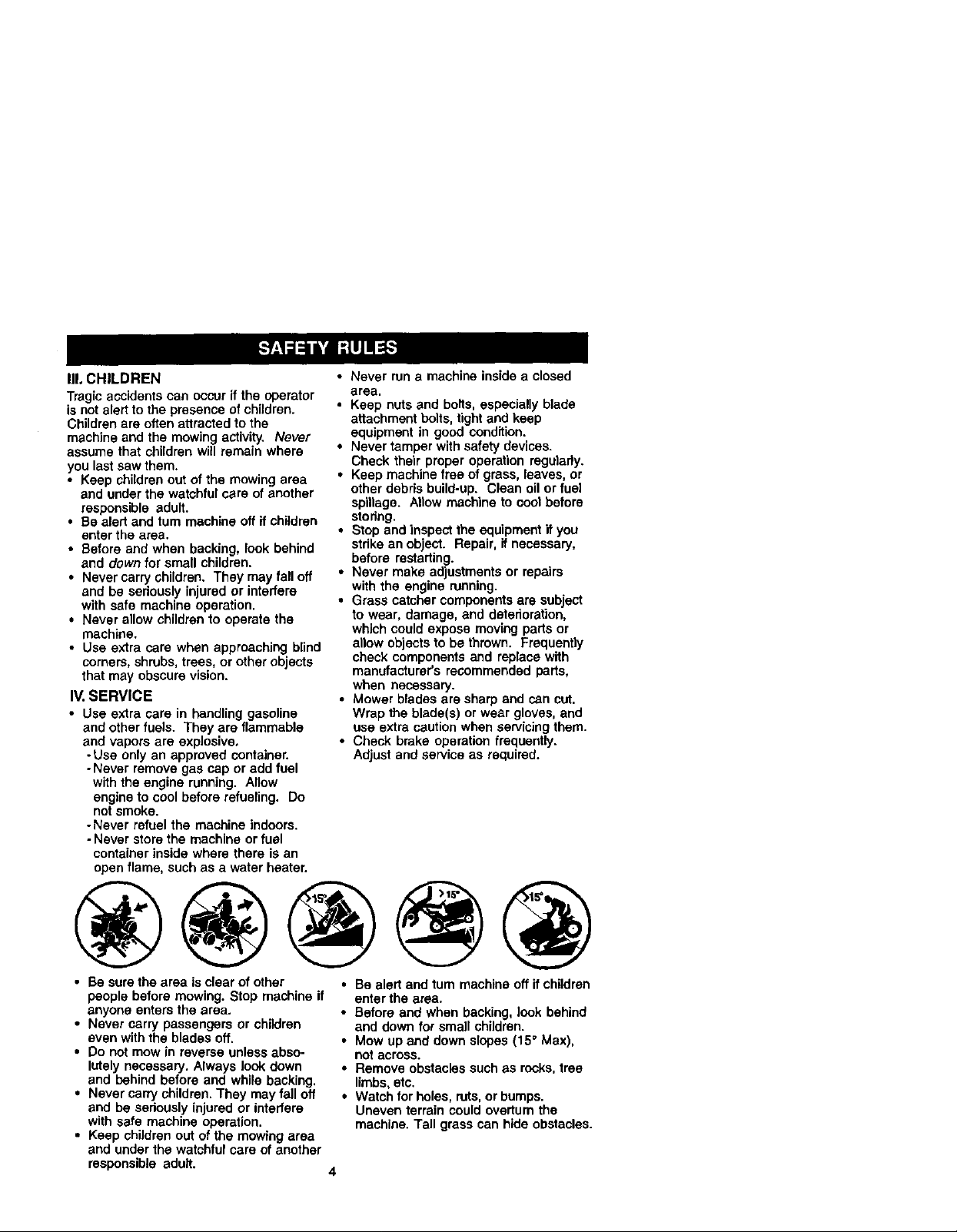
|11.CHILDREN
Tragicaccidents can occur ff the operator
is notalert to the presence of children.
Childrenare often attracted to the
machine and the mowing activity. Never
assume that children will remain where
you last saw them.
• Keep children out of the mowing area
and under the watchful care of another
responsible adult.
• Be alert and turnmachine off il children
enter the area.
• Before and when backing, look behind
and down for small children.
• Never carry children. They may fall off
and be seriously injured or interfere
with safe machine operation.
• Never allow childrento operate the
machine.
• Use extra care when approaching blind
corners, shrubs, trees, or other objects
that may obscure vision.
IV, SERVICE
• Use extra care in handling gasoline
and other fuels. They are flammable
and vapors are explosive.
-Use only an approved container.
-Never remove gas cap or add fuel
with the engine running. Allow
engine to cool before refueling. Do
notsmoke.
- Never refuel the machine indoors.
- Never storethe machine or fuel
container inside where there is an
open flame, such as a water heater.
• Never run a machine inside a closed
area.
• Keep nuts and bolts, especially blade
attachment bolts, tight and keep
equipment in good condition.
• Never tamper with safety devices.
Check their proper operation regularly.
• Keep machine free of grass, leaves, or
other debris build-up. Clean oil or fuel
spillage. Allow machine to cool before
storing.
• Stop and inspect the equipment "ityou
stdke an object. Repair, if necessary,
before restarting.
• Never make adiustments or repairs
with the engine running.
• Grass catcher components are subject
to wear, damage, and deterioration,
which could expose moving parts or
allow objects to be thrown. Frequently
check components and replace with
manufacturer's recommended parts,
when necessary.
• Mower blades are sharp and can cut.
Wrap the blade(s) or wear gloves, and
use extra caution when servicing them.
• Check brake operation frequently.
Adjust and service as required.
• Be sure the area is clear of other
people before mowing. Stop machine if
anyone enters the area.
• Never carry passengers or children
even with the blades off.
• Do not mow in reverse unless abso-
Ictely necessary. Always look down
and behind before and while backing.
• Never carry children. "]'hey may fall off
and be seriously Injured or interfere
with safe machine operation.
• Keep children out of the mowing area
and under the watchful care of another
responsible adult.
• Be alert and turn machine off if children
enter the area.
• Before and when backing, look behind
and down for small children.
• Mow up and down slopes (15° Max),
not across.
• Remove obstacles such as rocks,tree
limbs, etc.
• Watch for holes, ruts,orbumps.
Uneven terrain could overturn the
machine. Tall grass can hide obstacles.
4

• Useslow speed. Choose a low gear so
that you will not have to stop or shift
whUe on the slope.
• Avoid starting or stopping on a slope. If
tires lose traction, disengage the
blades and proceed slowly straight
down the slope.
• If machine stops while going uphill,
disengage blades, shift into reverse
and back down slowly.
• Do not turn on slopes unless neces-
sary, and then, turn slowly and gradu-
ally downhill, if possible.
,J_Look for this symbol to point out
importantsafety precautions. Itmeans
CAUTIONIX! BECOMEALERTI!I YOUR
SAFETY IS INVOLVED.
,ACAUTION: In order to prevent acciden-
tal starting when setting up, transporting,
adjusting or making repairs, always
disconnect spark plug wire and place
wire where it cannot contactspark plug.
_'I_CAUTION: Do notcoast down a hill in
neutral, you may lose control of the
tractor.
ACAUTION: Tow only the attachments
that are recommended by and comply
with specifications of the manufacturer of
your tractor. Use common sense when
towing. Operate only at the lowest
possible speed when on a slope. Too
heavy of a load, while on a slope, is
dangerous. Tires can lose traction with
the ground and cause you to lose control
of your tractor.
4(_WARNING: Engine exhaust, some of its
constituents, and certain vehicle compo-
nents contain or emit chemicals known to
the State of California to cause cancer
and birth defects or other reproductive
harm.
A,WARNING: Batteryposts terminals and
related accassodes contain lead and ead
compounds, chemicals known to the State
of California to cause cancer and birth
defects or other reproductiveharm. Wash
hands after handling.

PRODUCTSPECIFICATIONS
3ASOLINE 3.5GALLONS
CAPACITY UNLEADED
_,NDTYPE: REGULAR
:)ILTYPE SAE 10W30(above32°F)
_API-SF-SJ): SAE5W-30 Ibelow32°F)
OIL CAPACITY: W/FILTER: 4.5 PINTS
W/OFILTER: 4.0 PINTS
SPARK PLUG: CHAMPION RC12YC
3AP: .030")
GROUND SPEED 1st 1.2
(MPH): 2nd 1.5
3rd 2.4
4th 3.5
5th 4.8
6th 5.3
REVERSE: 1.5
TIRE PRESSURE:FRONT: 14 PSI
REAR: 10 PSI
CHARGING
SYSTEM: 15 AMPS @ 3600 RPIV
BATTERY: AMP/HR: 30
MIN. CCA: 240
CASE SIZE: U1R
BLADE BOLT 45-55 FT. LBS.
TORQUE:
CONGRATULATIONS on your purchase
of a new tractor. It has been designed,
engineered and manufactured to give
you the best possible dependability and
performance.
Should you experience any problem you
cannot easily remedy, please contact
your nearest Sears or other qualified
service center. We have competent, well-
trained technicians and the proper tools
to serviceor repair this tractor.
Please read and retain thismanual. The
instructionswill enable you to assemble
and maintain yourtractor properly.
Always observethe "SAFETY RULES".
REPAIR AGREEMENT
A Repair Agreement is available on this
product. Contact your nearest Sears
store for details.
CUSTOMER RESPONSIBILITIES
• Read and observe the safety rules.
• Follow a regular schedule in maintain-
ing, cadng for and usingyour tractor.
• Follow the instructionsunder =Mainte-
nance"and "Storage" sectionsof this
owner's manual.
_I_WARNING: This tractor is equipped
with an internal combustion engine and
should not be used on or near any
unimproved forest-covered, brush-
covered or grass-covered land unless the
engine's exhaust system is equipped with
a spark arrester meeting applicable local
or state laws (if any). If a spark arrester is
used, it should be maintained in effective
working order bythe operator.
In the state of Calitomia the above is
required by law (Section 4442 of the
California Public Resources Code).
Other states may have similarlaws.
Federal laws apply on federal lands. A
spark arrester for the muffler is available
through your nearest Sears service
center. (See REPAIR PARTS section of
this manual).

_her
Steering
Wheel
Insert
17/32x 1-3/16 x 12
(1) Knob_ Gauge
Steering Wheel
Steedng Sleeve
Mower
(5) Retainer Spdngs
(double loop) - _P (1)Front Plate
_ ,_ s
(2) Retainer Springs(single loop)
_ f (4) AdjustingBar
(4) Shoulder Bolt _
(4) Retainer Spdngs (4) Wheels
(double loop)
(2) Locknuts 5/16-18
I IIIIIIIIIIIIIIIIHII,H]_ _._, Nose Roller
IF ',2)Hex Bolts 5/16-18 x, _ Nr°ScekRs°ller (2) Washers
Cassette For Future Use
@
(4) Locknut 3/8-16
t7/32 x 7/8 x 16 Ga.
Key Slope Sheet
7

Your new tractor has been assembled at the factory wffh exception of those parts left
unassembled for shipping purposes. To ensure safe and proper operation of your
tractor all parts and hardware you assemble must be tightened securely. Use the
correct tools as necessary to insure proper tightness. Review the video cassette before
you begin.
TOOLS REQUIRED FOR ASSEMBLY
A socket wrench set will make assembly
easier. Standard wrench sizes you need
are listed below.
(1) 9/16" Wrench (1) 3/4" Socket w/
(1) 1/2" wrench drive ratchet
(1) Utilityknife (1) Pliers
(1) Tire pressure gauge
When right or left hand is mentioned in
this manual, it means, from your point of
view,when you are in the operating
position (seated behind the steering
wheel).
TO REMOVETRACTOR FROM
CARTON
UNPACK CARTON
1. Remove all accessible loose parts
and parts boxes from shipping carton.
2. Cut, from topto bottom, along lines on
all four comers of shipping carton, and
lay panels flat.
3. Remove mower and package materi-
als.
4. Check for any additional loose parts
or boxes and remove.
BEFORE REMOVING TRACTOR
FROM SKID
AI"I'ACH STEERING WHEEL
1. Remove lock nut and large flat washer
from steering shaft.
2. Positionfront wheels of the tractor so
they are pointing straight forward.
3. Slide the steering sleeve over the
steering shaft.
4, Positionsteering wheel so cress bars
are horizontal (left to right) and slide
onto steering wheel adapter.
5. Secure steering wheel to steering
shaft with lock nut and large flat
washer previously removed. Tighten
securely.
6. Snap steering wheel insert intocenter
of steering wheel.
7. Remove protective materials from
tractor hood and grill.
IMPORTANT: Check for and remove any
staplesin skidthat may puncture tires
where tractor is to roll off skid.
HOWTO SET UPYOURTRACTOR
CHECK BA'n'ERY
I. Lifthood to raised position.
NOTE: If thisbattery isput intoservice
after month and year indicated on label
(label located between terminals) charge
batteryfor minimum of one hour at 6-10
amps. (See "BA'I-I'ERY" in MAINTE-
NANCE section of this manual for
charging instructions).
INSTALL SEAT
Adjust seat before tightening adjustment
knob.
1. Remove adjustment knob and flat
washer securing seat to cardboard
packing and set aside for assembly of
8 seat to tractor.

2. Pivot seat upward and remove from
the cardboard packing. Remove the
cardboard packing and discard.
3. Place seat on seat pan so head of
shoulder bolt is positioned over large
slotted hole in pan.
4. Push down on seat to engage
shoulder bolt in slot and pull seat
towards rear of tractor.
5. Pivot seat and pan forward and
assemble adjustment knob and flat
washer loosely. Do not tighten.
6. Lower seat into operating position and
sit in seat.
7. Slide seat until a comfortable position
is reached which allows you to press
clutch/brake pedal all the way down.
8. Get off seat without moving its
adjusted position.
9. Raise seat and tighten adjustment
knob securely.
Seat Pan'--.
FlatWasher
NOTE: You may now roll or drive your
tractor oft the skid. Followthe appropriate
instructionbelow to remove the tractor
from the skid.
Seat
Shoulder
Bolt
TO ROLLTRACTOR OFF SKID (See
Operation section for location and
function of controls)
1. Press lift lever plunger and raise
attachment liftlever to its highest
position.
2. Release parking brake by depressing
clutch/brake pedal.
3. Place gearshift lever in neutral (N)
position.
4. Roll tractor forward off skid.
TO DFIIVETRACTOR OFF SKID (See
Operation section for location and
function of controls)
AWARNING; Before startinchread,
understand and follow all instructionsin
the Operation sectionof this manual. Be
sure tractor isin a well-ventilated area. Be
sure the area in front of tractorisclear of
other people and objects.
1. Be sure all the above assembly steps
have been completed.
2. Check engine oil level and fill fuel
tank with gasoline.
3. Sit on seat in operating position,
depress clutch/brake pedal and set
the parking brake.
4. Place gear shift lever in neutral (N)
position.
5. Press liftlever plunger and raise
attachment lift lever to its highest
position.
6. Start the engine. After engine has
started, move throttle controlto idle
position.
7. Depress clutch/brake pedal into full
"BRAKE" position and hold. Move
gearshift lever to 1st gear.
8. Slowly release clutch/brake pedal and
slowly drive tractor off skid.
9. Apply brake to stop tractor, set parking
brake and place gearshift lever in
neutral position.
t0.Tum ignition key to "OFF" position.
Continue with the instructionsthat follow.

ASSEMBLE GAUGEWHEELSTO
MOWER DECK
The gauge wheels are designed to keep
the mower deck in proper positionwhen
operatingmower. Be sure they are
properly adjusted to ensure optimum
mower performance.
1. Slide gauge wheel bar down into
bracket channel, Be sure that gauge
wheel bar aligning holes are on top.
Assemble gauge wheels as shown
using shoulder bolts,3/8 washers and
3/8-16 center Iocknuts and tighten
securely.
2. For ease of mower to traCtor assem-
bly raise gauge wheels to highest
position and retain with clevis pns
and spring retainers.
NOTE: Adjust gauge wheels before
operatingmower. See "TO ADJUST
GAUGE WHEELS" in the Operation
sectionof this manual.
Gauge
3/8
Locknut
TO ATTACH NOSE ROLLER
1. Position brackets, 17/32 x 7/8 x 16
gauge washers, and nose roller
between deck mounting brackets as
shown. Be sure to position brackets
on correct side, as shown.
2. Installhex bolts and lock nuts as
shown. Tighten hardware securely.
NOTE: Be sure bracket tabs are posi-
tioned in tab holes in deck brackets.
TabHole
Nose Roller
ut "B" Bracket
Hex_
Bracket ,_ _.w
Washer
INSTALL MOWER AND DRIVE BELT
Be suretractorison levelsurfaceandmower
suspensionarms are raisedwith attachment
liftcontrol.Engage parkingbrake.
1. Cut and remove ties securing anti-
sway bar and belts. Swing anti-sway
barto leftside of mower deck.
2. Slide mower under tractorwith
deflector shield to dght side oftractor.
IMPORTANT; Check belt for proper
routing in all mower pulley grooves,
3. If equipped,turn height adjustment
knob counterclockwise until it stops.
4. Lower mower linkage with attachment
liftcontrol.
5. Be sure belt tension rod is in disen-
gaged position.
6. Install belt into electdc clutch pulley
groove.
7. Place the suspension arms on
outward pointing deck pins. Retain
with double loop retainer spring with
loops up as shown.
8. Installfront plate assembly to tractor
suspension brackets and retain with
single loop retainer spdngs as shown.
10
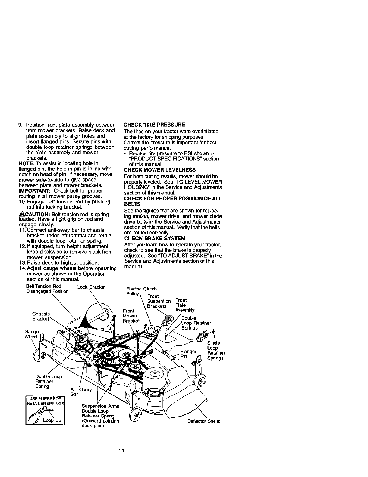
9. Positionfrontplateassemblybetween
front mower brackets. Raise deck and
plate assembly to align holes and
insert flanged pins. Secure pins with
double loop retainer springs between
the plate assembly and mower
brackets.
NOTE: To assist in locating hole in
flanged pin, the hole in pin is inline with
notchon head of pin. If necessary,move
mower side-to-side to give space
between plate and mower brackets.
IMPORTANT: Check belt for proper
routingin all mower pulley grooves.
10.Engage belttension rod by pushing
rod into locking bracket.
_CAUTION: Belttension rod is spring
loaded. Have a tight grip on rod and
engage slowly.
1t.Connect anti-sway bar to chassis
bracket under left footrestand retain
with double loop retainer spring.
12.If equipped, turn height adjustment
knob clockwise to remove slack from
mower suspension.
13. Raise deck to highest position.
14.Adjust gauge wheels before operating
mower as shown in the Operation
section of this manual.
BeltTensionRod LockBracket
DisengagedPosition
CHECK TIRE PRESSURE
The tireson your tractorwere overinflated
at the factory forshippingpurposes.
Correcttirepressure isimportantfor best
cutting performance.
• Reduce tire pressureto PSI shown in
"PRODUCT SPECIFICATIONS" section
ofthis manual.
CHECK MOWER LEVELNESS
For best cutting results,mower should be
properlyleveled. See "TO LEVEL MOWER
HOUSING" in the Service and Adjustments
section of this manual.
CHECK FOR PROPER POSITION OF ALL
BELTS
See the figuresthat are shownfor replac.
ing motion,mower drive, and mower blade
drive belts in the Service and Adjustments
sectionof thismanual. Verifythat the belts
are routed correctly.
CHECK BRAKE SYSTEM
Afteryou learn howto operate yourtractor,
checkto see thatthe brake isproperly
adjusted. See "TO ADJUST BRAKE" inthe
Service and Adjustments sectionof this
manual.
ElectdcClutch
Pulley\ Front
\ Suspention Front
Chassis
Gauge
Wheel
\
Double Loop
Retainer
Spdng
USE PLIERS FOR
RETAINER SPRING_
Anti-Sway
Bar
Suspension Arms
Double Loop
Retainer Spdng
(Outward pointing
deck pins)
Front _Brackets Plate
Mower
Bracket\
11
,.Loop Retainer
Single
Flanged Retainer
Deflector Shaild
Loop
Spdngs

_ CHECKLIST
Before you operate and enjoy your new
tractor,we wishto assure that you receive
the best performance and satisfaction
from this quality product.
Please review the following checklist:
4 NI assembly instructionshave been
completed.
J' No remaining loose parts in carton.
J"Battery is propedy prepared and
charged.(Minimum 1 hour at 6 amps).
,/Seat is adjusted comfortably and
tightened securely.
J All tires are propedy Inflated. (For
shipping purposes, the tires were
overinflated at the factory).
•/ Be sure mower deck is propedy leveled
side-to-side/front-to-rear for best cutting
results. (Tires must be propedy inflated
for leveling).
,/Check mower and ddve belts. Be sure
they are routed propedy around pulleys
and inside _dl belt keepers.
#' Check wiring. See that all connections
are still secure and wires are propedy
clamped.
While learning how to use your tractor,
pay extra attention to the following
important items:
•/ Engine oil is at proper level.
J Fuel tank is filled with fresh, clean,
regular unleaded gasoline.
,/Become familiar with all controls - their
|ocation and function. Operate them
before you start the engine.
,/Be sure brake system is in safe
operating condition.
12

These symbols may appear on your tractor or in literature supplied with the product.
Learn and understand their meaning.
A =,
BATFERY CAUTION OR REVERSE FORWARD FAST SLOW
ENGINE ON ENGINE OFF OIL PRESSURE LIGHTS ON OVER TEMP
FUEL CHOKE MOWER HEIGHT PARKING BRAKE UNLOCKED
WARNING
LOCKED
LIGHT
MOWERLI_
r_'_ R N H L
ATrACHMENT REVERSE NEUTRAL HIGH LOW PARKING BRAKE
CLUTCH ENGAGED
ATTACHMENT
CLUTCH DISENGAGED (SEE SAFETY RULES SECTION)
KEEP AREA CLEAR SLOPE HAZARDS
!
DANGER, KEEP HANDS AND FEET AWAY
FREE WHEEL
(Automatic Models only)
13

KNOWYOUR TRACTOR
READ THIS OWNER'S MANUAL AND SAFETY RULES BEFORE OPERATING
YOUR TRACTOR
Compare the illustrationswith yourtractor to familiarize yourself with the locationsof
various controlsand adjustments. Save this manual for future reference.
Ammeter Hourmeter
Throttle Control
Clutch/Brake
Control
Choke Control Attachment
Gear_
Lever
Our tractors conform to the safety standards of the American
National Standards Institute.
witch
Plunger
Attachment
AI"rACHMENT CLUTCH SWITCH: Used
to engage the mower blades, or other
attachments mounted to your tractor.
LIGHT SWITCH: Turnsthe headlightson
and off.
THROTTLE CONTROL - Used to control
engine speed.
CHOKE CONTROL - Used when starting
a cold engine.
CLUTCH/BRAKE PEDAL: Used for
declutching and braking the tractor and
starting the engine.
GEARSHIFT LEVER - Selects the speed
and directionof tractor.
ATTACHMENTUFT LEVER - Usedto raise,
lower,and adjustthe mowerdeckor other
attachmentsmountedto yourtractor.
LIFT LEVER PLUNGER: Used to release
attachment lift lever when changing its
position.
IGNmON SWITCH: Used for startingand
stoppingthe engine.
AMMETER: Indicates battery charging (+)
or discharging (-).
PARKING BRAKE: Locks clutch/brake
intothe brake position.
HOURMETER- Indicateshoursof operation.
14
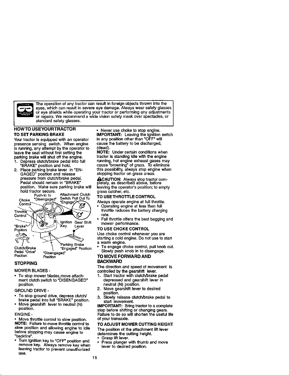
Theoperationofanytractorcanresultinforeignobjectsthrownintothe !
eyes, which can result in severe eye damage. Always wear safety glasses I
or eye shields while operating your tractor or performing any adjustments
or repairs. We recommend a wide vision safety mask over spectacles, or
standard safety g asses.
HOWTO USEYOURTRACTOR
TO SET PARKING BRAKE
Yourtractor is equipped with an operator
presence sensing switch. When engine
is running, any attempt by the operator to
leave the seat withoutfirst settingthe
parking brake will shut off the engine.
1. Depress clutch/Drakepedal into full
=BRAKE" positionand hold.
2. Place parking brake lever in "EN-
GAGED" positionand release
pressure from clutch/brake pedal.
Pedal should remain in=BRAKE"
position. Make sure parking brake will
holdtractor secure.
Choke "Disengage .._.___'SwitchPullOutTo
Th_C°ntr°l " " __'_
=Brake Key Lever
P ition o _
__ \Ignition Gear Shift
Push-Into Attachment Clutch
">a, ogBrae
Clutch/Brake "Engaged"Position
Pedal=Ddve" =Disengaged"
Position Position
STOPPING
MOWER BLADES -
• To stop mower blades,move attach-
ment clutch switchto =DISENGAGED"
position.
GROUND DRIVE -
• To stop ground ddve, depress clutch/
brake pedal Into full =BRAKE" position.
• Move gearshift lever to neutral (N)
position.
ENGINE -
• Move throttle controlto slow position.
NOTE: Failure to move throttlecontrolto
slow position and allowing engine to idle
before stoppingmay cause engine to
"backfire".
• Turn ignitionkey to =OFF" position and
remove key. Always remove key when
leaving tractor to prevent unauthorized
USe.
• Never use choke to stop engine.
IMPORTANT: Leaving the ignition switch
in any position other than "OFF" will
cause the battery to be discharged,
(dead).
NOTE: Under certainconditionswhen
tractor is standing idle with the engine
running, hot engine exhaust gases may
cause "browning" of grass. To eliminate
this possibility,always stop engine when
stoppingtractor on grass areas.
ACAUTION: Always stoptractor com-
pletely, as descdbeiJ above, before
leaving the operator's position;to empty
grass catcher, etc.
TO USE THRO'I'rLE CONTROL
Always operate engine at full throttle.
• Operating engine at less than full
throttle reduces the battery charging
rate.
• Full throttle offers the best bagging and
mower performance.
TO USE CHOKE CONTROL
Usa choke control whenever you are
starting a cold engine. Do not use to start
a warm engine.
• To engage choke control, pull knob out.
Slowly push knob in to disengage.
TO MOVE FORWARD AND
BACKWARD
The direction and speed of movement is
controlledby the gearshift lever.
1. Start tractor with clutch/brake pedal
depressed and gearshift lever in
neutral (N) position.
2. Move gearshift lever to desired
position.
3. Slowly release clutch/brake pedal to
start movement.
IMPORTANT: Bring tractor to a complete
stop before shifting or changinggears.
Failure to do so will shorten the useful life
of your transaxle.
TO ADJUST MOWER CUTTING HEIGHT
The position of the attachment lift lever
determines the cutting height.
• Grasp lift lever.
• Press plunger with thumb and move
lever to desired position.
15

Thecuttingheight range is approxi-
mately 1-1/2 to 4=. The heightsare
measured from the ground to the blade
tipwiththeenginenotrunning.These
heights are approximate and may vary
depending upon soil conditions, height of
grass and types of grass being mowed.
• The average lawn should be cutto
approximately 2-1/2 inches during the
coolseason and to over 3 inches
during hot months. For healthier and
better looking lawns, mow often and
after moderate growth.
• For best cuttingperformance, grass
over 6 inches in height should be
mowed twice, Make the first cut
relatively high;the second to desired
height.
TO ADJUST GAUGE WHEELS
Gauge wheels are properly adjusted
when they are slighlly off the ground
when mower is at the desired cutting
height in operating position.Gauge
wheels then keep the deck in proper
positionto help prevent scalping in most
terrain conditions.
NOTE: Be sure tractor is on a flat level
surface.
1. Lower mower and adjust mower to
desired cutting height.
2. Remove retainer spring and clevis pin
which secure each gauge wheel bar.
3. Lower gauge wheels to ground. Raise
gauge wheels slightlyto align holes in
bracket and gauge wheel bar and
insett clevis pin. Gauge wheels
should be slightly off the ground.
4. Replace re'_ainerspring into clevis pin.
5. Besure all gauge wheels are in the
same setting.
IMPORTANT: Be sure to readjust gauge
wheels if you change the cuttingheight
ofthe mower deck.
Retainer
.... Pin
TO OPERATE MOWER
Yourtractor is equipped with an operator
presence sensing switch. Any attempt by
the operator to leave the seat with the
engine runningand the attachment clutch
engaged will shut off the engine.
Clevis
1. Select desired height of cut,
2. Start mower blades by engaging
attachment clutchcontrol.
TO STOP MOWER BLADES -
disengage attachment clutch control.
,_kCAUTION: Do notoperate the mower
withouteither the entire grass catcher, on
mowers so equipped, or the deflector
shield in place.
Attachment Clutch
Switch PullOut To
=Engage"
Push In To
"Disengage"
Attachment lifl Lever
High Position
_Low
position
•\ Deflector
Shield
TO OPERATE ON HILLS
_I,CAUTION: Do not drive up or down
hills with slopes greater than 15° and do
not drive across any slope.
• Choose the slowest speed before
starting up or down hills.
• Avoid stopping or changing speed on
hilts.
• If slowing is necessa_, move throttle
controllaver to slower position.
• If stoppingis absolutely necessary,
push clutch/brake pedal quickly to
brake positionand engage parking
brake.
• Move gearshift lever to 1stgear. Be
sure you have allowed room fortractor
to rollslightlyas you restart movement.
• To restart movement, slowly release
parking brake and clutch/brake pedal.
• Make all turns slowly.
TOTRANSPORT
• Raise attachment lift to highest position
with attachment liftcontrol.
• When pushing or towing your tractor,
be sure gearshift lever is in neutral (N)
position.
• Do not push or towtractor at more than
five (5) MPH.
NOTE: To protect hoodfrom damage
when transporting your tractor on a truck
or a trailer, be sure hood is closed and
securedto tractor. Use an appropriate
means of _ying hood to tractor (rope, cord,
etc.).
16

TOWING CARTS AND OTHER ATrACH-
MEN'IS
Tow only the attachments that are
recommended by and comply with
specifications ofthe manufacturer of your
tractor. Use commonsense when towing.
Too heavy ofa loud, while on a slope, =s
dangerous. Tires can lose traction with
the ground and cause you to lose control
ofvour tractor.
BEFORE STARTINGTHE ENGINE
CHECK ENGINE OIL LEVEL
The engine in your tractor has been
shipped, from the factory, already filled
with summer weightoil.
1. Check engine oil with tractor on level
ground.
2. Unthread and remove oil fill cap/
dipstick;wipe oil off. Reinsert the
dipstickinto the tube and rest oil fill
cap on the tube. Do not thread the
cap ontothe tube. Remove and read
oil level. If necessary, add oil until
"FULL" mark on dipstickis reached.
Do not overfill.
• For cold weather operation you should
change oilfor easier starting(See "OIL
VISCOSITY CHART" in the Mainte-
nance sectionof thismanual).
• To change engine oil,see the Mainte-
nance section in thismanual.
ADD GASOLINE
• Fill fuel tank. Use fresh, clean, regular
unleaded gasoline with a minimumof
87 octane. (Use of leaded gasoline will
increase carbon and lead oxide
deposits and reduce valve life). Do not
mix oil with gasoline. Purchase fuel in
quantitiesthat can be usedwithin 30
days to assure fuel freshness.
IMPORTANT: When operating in tem-
peratures below 32°F(O°C), use fresh,
clean winter grade gasoline to help
insure good cold weather starting.
a_cWARNING: Experience indicates that
ohol blended fuels (called gasohol or
using ethanol or methanol) can attract
moisturewhich leads to separation and
formation of acids during storage. Acidic
gas can damage the fuel system of an
engine while in storage. To avoid engine
problems, the fuel system should be
emptied before storage of 30 days or
longer.Drain the gas tank, start the
engine and let it run untilthe fuel lines
and carburetor are empty. Use fresh fuel
nextseason. See Storage Instructionsfor
additional information. Never use engine
or carburetor cleaner productsin the fuel
tank or permanent damage may occur.
ACAUTION: Fillto bottom of gas tank
filler neck. Do notoverfill Wipe off any
spilled oil or fuel. Do not store, spill or use
gasoline near an open flame.
TO START ENGINE
When startingthe engine for the first time
or if the engine has run out of fuel, it will
take extra crankingtime to move fuel from
the tank to the engine.
1. Sit on seat in operatingposition,
depress clutch/brake pedal and set
parking brake.
2. Place gear shift lever in neutral (N)
position.
3. Move attachment clutch to =DISEN-
GAGED" position.
4. Move throttle control to fast position
5. Pull choke control out for a cold
engine start attempt. For awarm
engine start attempt the choke control
may not be needed.
NOTE: Before starting, read the warm and
cold starting procedures below.
6. Insert key into ignition and turn ke_/
clockwise to "START" position an(I
release key as soon as engine stads.
Do not run starter continuously for
more than fifteen seconds per minute.
If the engine does not start after
several attempts, push choke control
in, wait a few minutes and try again. If
engine still does not start, pull the
choke control out and retry, o
WARM WEATHER STARTING (50 F and
above)
7. When engine starts, slowly push
choke control in untilthe engine
begins to runsmoothly. If the engine
starts to run roughly, pull the choke
control out slightlyfor a few seconds
and then continueto push the control
in slowly.
• The attachments and ground drive can
now be used. If the engine does not
accept the load, restart the engine and
allow it to warm up for one minute
using the choke as described above.
COLDWEATHER STARTING (50 F and
below)
7. When engine starts, slowly push
choke control in until the engine
begins to run smoothly. Continue to
push the choke control in small steps
allowing the engine to accept small
changes in speed and load, untilthe
choke control isfully in. If the engine
starts to run roughly,pull the choke
control out slightlyfor a few seconds
and then continueto push the control
in slowly. This may require an engine
warm-up period from several seconds
to several minutes, depending on the
17 temperature.

• Theattachmentscanbeusedduring
theengine warm-up period and may
require the choke control be pulled out
slightly.
NOTE=ffat a highaltitude(above3000 feet)
orincoldtemperatures(below3_ F)the
carburetorfuel mixture may needto be
a_usted forbest enginepeffo.n'na_r_ce.See
"TO ADJUST CARBURETOR intheService
andA_ustrnents sec_onof thismanual.
MOWlNGTIPS
• Mower should be propedy Leveledfor
best mowing performance. See "TO
LEVEL MOWER HOUSING" in the
Service end Adjustments section of this
manual.
• The left hand side of mower should be
used for trimming.
• Drive sothat clippings are discharged
onto the area that has been cut. Have
the cutarea to the right of the tractor.
This will result in a more even distribu-
lion of clippingsand more uniform
cutting.
• When mowing large areas, start by
turningto the right so that clippings will
discharge away from shrubs, fences,
driveways, etc. After one or two rounds,
mow in the opposite direction making
left hand turns untilfinished.
• If grass is extremelytall, itshould be
mowed twice to reduce load and
possiblefire hazard from dded clip-
pings. Make first cut relatively high; the
second to the desired height.
• Do not mow grass when itis wet. Wet
grass will plug mower and leave
undesirable clumps. Allow grass to dry
before mowing.
• Always operate engine at full throttle
when mowing toassure better mowing
performance end proper discharge of
material. Regulate ground speed by
selecting a low enough gear to give the
mower the best cutting performance as
well as the quality of cut desired.
• When operating attachments, select a
groundspeed that will suitthe terrain
and give best performance ofthe
aftachment being used.
f
J
18
Check Brake Op, orat_ofl _/ ft_
CheCk Tire Pressure _
CheCk Operato_ Pr_ and
_-_,_'_ SE RVIC E DATES
R CheckforLooseFasleners _ IbJz If
.SharperYRep_..eMower Blades I/'4
T L_=.,o. chart l/ V'
0 Ch,_J<B_o,y_ I./.
R CleanBatte_andT(_-nllr_ls _ 4b_
CheCk Trans.)de COOling
Adjust Blade Be_t(s) T_malon _s
_d_ust Motior= Drive Be/t (s) Tension _s
ch,_<E,'_ C,IL_= V' V"
E clean A_rRlter _=
N Clean A_rScreen IV/=
G InSpectk'x_llk)rP3parkA_rester
i_ Replace (311F_tter(If equipped) V_=
E Clean _glne _ll_g Fins _=
R_aC_spar_F_ug I,/ t,/
Replace Air Rlter P_per Cart_dge ll_/_
P_ F_ R_, V'
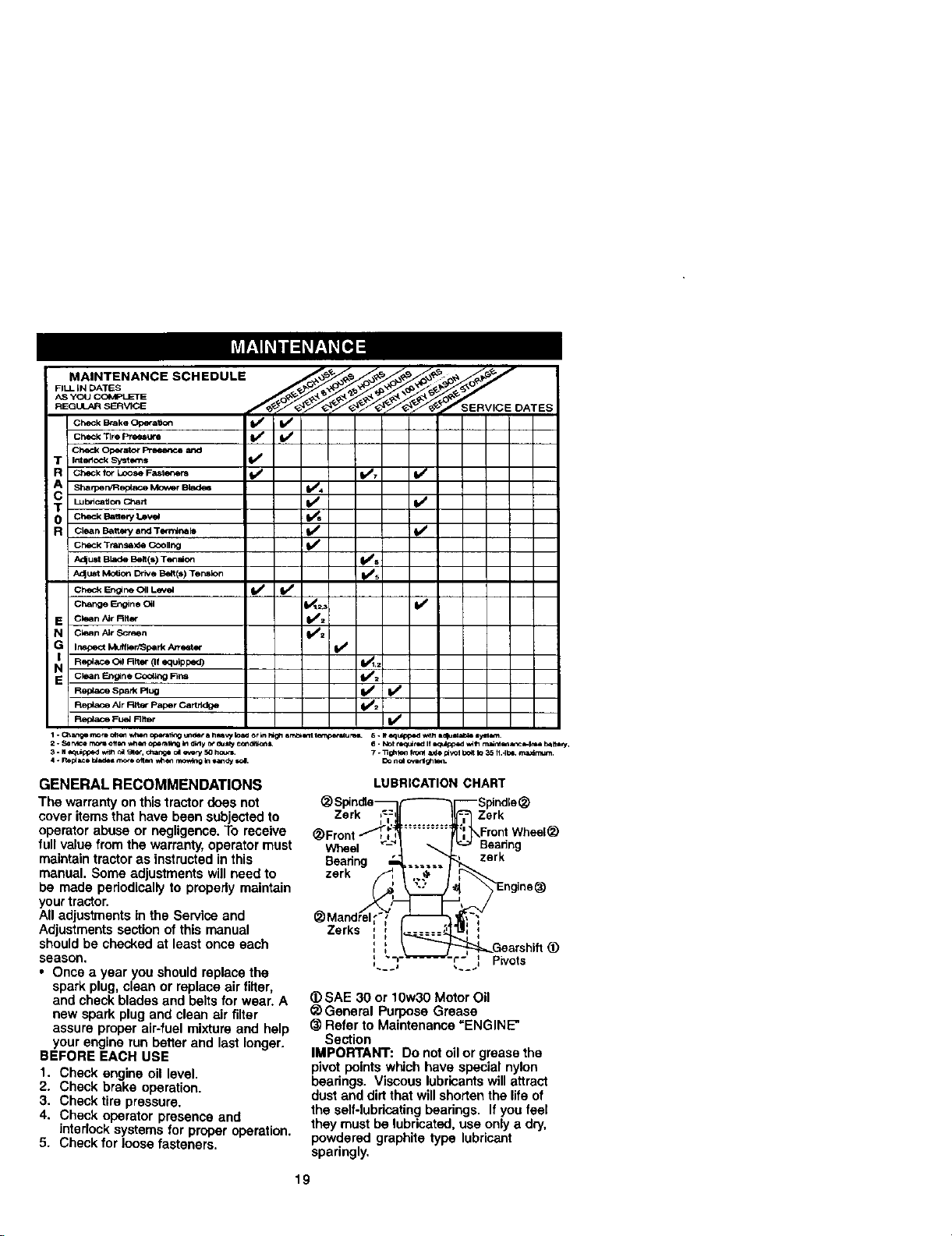
GENERAL RECOMMENDATIONS
The warranty on this tractor does not
cover items that have been subjectedto
operator abuse or negligence. To receive
full value from the warranty, operator must
maintaintractor as instructed in this
manual. Some adjustments willneed to
be made periodicallyto properly maintain
your tractor.
All adjustments in the Service and
Adjustments section of this manual
should be checked at least once each
season.
• Once a year you should replace the
spark plug, clean or replace air filter,
and check blades and belts for wear. A
new spark plug and clean air filter
assure properair-fuel mixture and help
your engine run better and last longer.
BEFORE EACH USE
1. Check engine oil level.
2. Check brake operation.
3. Check tire pressure.
4. Check operator presence and
interlock systems for proper operation.
5. Check for loose fasteners.
LUBRICATION CHART
_ Spindte_ (-----_1--- Spindle(_
Zerk ,=:, Zerk
(_ Front __Front Whe_l _
_ Mandre/_l_"_>'/,'_
Zerks ; I 1_..3_1 I,,, ;
i I,
_) SAE 30 or 10w30 Motor Oil
_) General Purpose Grease
(_ Refer to Maintenance =ENGINE*
Section
IMPORTANT: Do not oil or grease the
pivot points which have special nylon
bearings. Viscous lubricantswill attract
dust and dirtthat willshorten the life of
the self-lubdcating bearings. If you feel
they must be lubricated, use only a dry,
powdered graphite type lubricant
sparingly.
19

TRACTOR
Alwaysobservesafety rules when
pedorming any maintenance.
BRAKE OPERATION
If tractor requiresmore than six (6) feet
stoppingdistance at high speed in
highestgear, then brake must be ad-
justed. (See "TO ADJUST BRAKE" in the
Service and Adjustments section of this
manuel).
TIRES
• Maintain proper air pressure in all tires
(See "PRODUCT SPECIFICATIONS"
section of this manual)_
• Keep tiresfree of gasoline, oil, or insect
control chemicals which can harm
rubber.
• Avoid stumps, stones, deep ruts, sharp
objects and other hazards that may
cause tire damage.
NOTE; To seal tire punctures and prevent
flat tires due to slow leaks, tire sealant
may be purchased from your local parts
dealer. Tire sealant also prevents tire dry
rot and corrosion.
OPERATOR PRESENCE SYSTEM
Be sure that operator presence and
interlock systems are working properly. If
your tractor does not function as de-
scribed below, repair the problem
immediately.
• The engine should not start unless the
clutch/brake pedal is fully depressed
and attachment clutch control is in the
disengaged position.
• When the engine is running, any
attempt bythe operator to leave the
seat without first setting the parking
brake should shut off the engine.
• When the engine is running and the
attachment clutch is engaged, any
attempt bythe operator to leave the
seat should shut offthe engine.
• The attachment clutch should never
operate unless the operator is in the
seat.
BLADE CARE
For best results mower blades must be
kept sharp. Replace bent or damaged
blades.
BLADE REMOVAL
1. Raise mower to highest positionto
allow access to blades.
2. Remove hex bolt, lock washer and flat
washer securing blade.
3. Install new or resharpened blade with
trailingedge up towards deck as
shown.
IMPORTANT: To ensure proper assembly,
center hole in blade must align with star
on mandrel assembly.
4. Reassemble hex bolt, lock washer
and flat washer in exact order as
shown.
5. Tighten bolt securely (45-55 Ft. Lbs.
torque).
IMPORTANT: Blade bolt is Grade 8 heat
treated.
TrailingEdgeUp _'_ - Mandrel
*A Grade8 heattreatedboltcanbe
identifiedbysixlines on thebolthead.
TO SHARPEN BLADE
NOTE: We do not recommend sharpen-
ing blade, but if you do, be sure the blade
is balanced,
Care should be taken to keep the blade
balanced. An unbalanced blade will
cause excessive vibration and eventual
damage to mower and engine.
• The blade can be sharpened with a file
or on a gdnding wheel. Do not attempt
to sharpen while it is on the mower.
• To check blade balance, you will need
a 5/8" diameter steel bolt, pin, or a cone
balancer. (When using a cone bal-
ancer, follow the instructionssupplied
with balanoer).
NOTE: Do not use a nail for balancing
blade. The lobes of the center hole may
appear to be centered, but are not.
• Slide blade onto an unthraaded portion
of the steel bolt or pin and hold the boil
or pin parallel with the ground. If blade
is balanced, it should remain in a
horizontal position. If either end of the
blade moves downward, sharpen the
heavy end untilthe blade is balanced.
5/8" Bolt or Pin-
BATrERY
Your tractor has a battery charging
system which is sufficient for normal use.
However, periodic charging of the battery
with an automotive charger will extend its
20 life.
Center Hole
Blade
 Loading...