

Craftsman 917272040 Owner’s Manual

Owner's Manual
rRRFTXMRN°
18.5 HP
ELECTRIC START
46" MOWER
AUTOMATIC
LAWN TRACTOR
Model No.
917.272040
• Safety
• Assembly
• Operation
• Maintenance
• Repair Parts
CAUTION:
Read and follow all
Safety Rules and Instructions
before operating this equip-
ment.
For answers to your questions
about this product, Call:
1-800-659-5917
Sears Craftsman Help Line
5 am - 5 pro, Mon- Sat
Sears, Roebuck and Co., Hoffman Estates, IL 60179
Visit our Craftsman website: www.sears,com/craftsman
Warranty .:...;...._;:...:,_..;;............................. 2
Safety Rules..'......_..-....._ ....................... 2
Product Specifications ..,.:: .................... 5
Assembly ...................... ,......................... 8
Operation .............................................. 12
Maintenance Schedule ......................... 19
LIMITED TWO YEAR WARRANTY ON CRAFTSMAN RIDING EQUIPMENT
For two (2) years from the date of purchase, if this Craftsman Riding Equipment is main-
tained, lubricated and tuned up according to the instructions in the owner's manual,
Sears will repair or replace, free of charge, any parts found to be defective in material or
workmanship,
This Warranty does not cover:.
• Expendable items which become worn during normal use, such as blades, spark
plugs, air cleaners, belts, etc.
• Tire replacement or repair caused by punctures from outside objects, such as nails,
thorns, stumps, or glass.
• Repairs necessary because of operator abuse, negligence, improper storage or acci-
dent or the failure to maintain the equipment according to the instructions contained in
the owner's manual.
• Riding equipment used for commercial or rental purposes.
Maintenance ......................................... 19
Service and Adjustments...................... 23
Storage ................................................. 30
Troubleshooting.................................... 31
Repair Parts ......................................... 35
Parts Ordering ....................... Back Cover
LIMITED 90 DAY WARRANTY ON BA'n'ERY
For ninety (90) days from date of purchase, if any battery included with this tiding equip-
ment proves defective in material or workmanship and our testing determines the bat-
tery will not hold a charge, Sears will replace the battery at no charge. In-home warranty
service on your Craftsman riding equipment is available at no charge for 30 days from
the date of purchase. Please contact your nearest service center. After 30 days from the
date of purchase, warranty service is available by taking your Craftsman ridingequip-
ment to your nearest Sears Service Center. (In-home warranty service will still be avail-
able after 30 days from the date of purchase but a standard tripcharge willapply). This
warranty applies only while this product is in the United States. This Warranty gives you
specific legal rights, and you may also have other rights which may vary from state to
state.
Sears, Roebuck and Co., D/817 WA, Hoffman Estates, IL 60179
GENERAL OPERATION
• Read, understand, and follow all instruc-
tions in the manual and on the machine
before starting.
• Only allow responsible adults, who are
familiar with the instructions, to operate
the machine.
• Clear the area of objects such as rocks,
toys, wire, etc., which could be picked
up and thrown by the blade.
• Be sure the area is clear of other people
before mowing. Stop machine if anyone
enters the area.
• Never carry passengers.
• Do not mow in reverse unless absolute-
ly necessary. Always look down and
behind before and while backing.
• Be aware of the mower discharge direc-
tion and do not point it at anyone. Do
not operate the mower without either
the entire grass catcher or the guard in
place.
• Slow down before turning.
• Never leave a running machine unat-
tended. Always turn off blades, set park-
ing brake, stop engine, and remove
keys before dismounting.
2

• Turn off blades when not mowing.
• Stop engine before removing grass
catcher or unclogging chute.
• Mow only in daylight or good artificial
light.
• Do not operate the machine while under
the influence of alcohol or drugs.
• Watch for traffic when operating near or
crossing roadways.
• Use extra care when loading or unload-
ing the machine into a trailer or truck.
SLOPE OPERATION
Slopes are a major factor related to loss-
of-control and tipover accidents, which
can result in severe injury or death. All
slopes require extra caution. If you cannot
back up the slope or if you feel uneasy on
it, do not mow it.
DO:
• Mow up and down slopes, not across.
• Remove obstacles such as rocks, tree
limbs, etc.
• Watch for holes, ruts, or bumps. Uneven
terrain could overturn the machine. Tall
grass can hide obstacles.
• Use slow speed. Choose a low gear so
that you will not have to stop or shift
while on the slope.
• Follow the manufacturer's recommen-
dations for wheel weights or counter-
weights to improve stability.
• Use extra care with grass catchers or
other attachments. These can change
the stability of the machine.
• Keep all movement on the slopes slow
and gradual. Do not make sudden
changes in speed or direction.
• Avoid starting or stopping on a slope. If
tires lose traction, disengage the blades
and proceed slowly straight down the
slope.
DO NOT:
• Do nottum on slopes unless necessary,
and then, turn slowly and gradually
downhill, if possible.
• Do not mow near drep-offs, ditches, or
embankments. The mower could sud-
denly turn over if a wheel is over the
edge of a cliff or ditch, or if an edge
caves in.
• Do not mow on wet grass. Reduced
traction could cause sliding.
• Do nottryto stabilize the machine by
putting your foot on the ground.
• Do not use grass catcher on steep
slopes.
CHILDREN
Tragic accidents can occur if the operator
is not alert to the presence of Children.
Children are often attracted to the
machine and the mowing activity. Never
assume that children will remain where
you last saw them.
• Keep children out of the mowing area
and under the watchful care of another
responsible adult.
• Be alert and turn machine off if children
enter the area.
• Before and when backing, look behind
and down for small children.
• Never carry children. They may fall off
and be seriously injured or interfere with
safe machine operation.
• Never allow children to operate the
machine.
• Use extra care when approachingblind
corners, shrubs, trees, or other objects
that may obscure vision.
SERVICE
• Use extra care in handling gasoline and
other fuels. They are flammable and
vapors are explosive.
Use only an approved container.
Never remove gas cap or add fuel
with the engine running. Allow en-
gine to cool before refueling. Do not
smoke.
Never refuel the machine indoors.
Never store the machine or fuel
container inside where there is an
open flame, such as a water heater.
• Never run a machine inside a closed
area.
• Keep nuts and bolts, especially blade
attachment bolts, tight and keep equip-
ment in good condition.
• Never tamper with safety devices.
Check their proper operation regulady.
• Keep machine free of grass, leaves, or
other debds build-up. Clean oil or fuel
spillage. Allow machine to cool before
stodng.
• Stop and inspect the equipment if you
strike an object. Repair, if necessary,
before resta_rting.
3
• Never make adjustments or repairs with
the engine running.
• Grass catcher components are subject
to wear, damage, and deterioration,
which could expose moving parts or
allow objects to be thrown. Frequently
check components and replace with
manufacturer's recommended parts,
when necessary.
• Mower blades are sharp and can cut.
Wrap the blade(s) or wear gloves, and
use extra caution when servicing them.
• Check brake operation frequently.
Adjust and service as required.
@@@@@
• Be sure the area is clear of other people
before mowing. Stop machine if anyone
enters the area.
• Never carry passengers.
• Do not mow in reverse unless absolute-
ly necessary. Always look down and
behind before and while backing.
• Never carry children. They may fall off
and be seriously injured or interfere with
safe machine operation.
• Keep children out of the mowing area
and under the watchful care of another
responsible adult.
• Be alert and turn machine off if children
enter the area.
• Before and when backing, look behind
and down for small children.
_,Look for this symbol to point out impor-
tant safety precautions. It means CAU-
TION!!! BECOME AWARE!!! YOUR SAFE-
TY IS INVOLVED.
_,CAUTION: In order to prevent acciden-
tal starting when setting up, transporting,
adjusting or making repairs always discon-
nect spark plug wire and place wire where
it cannot contact spark plug.
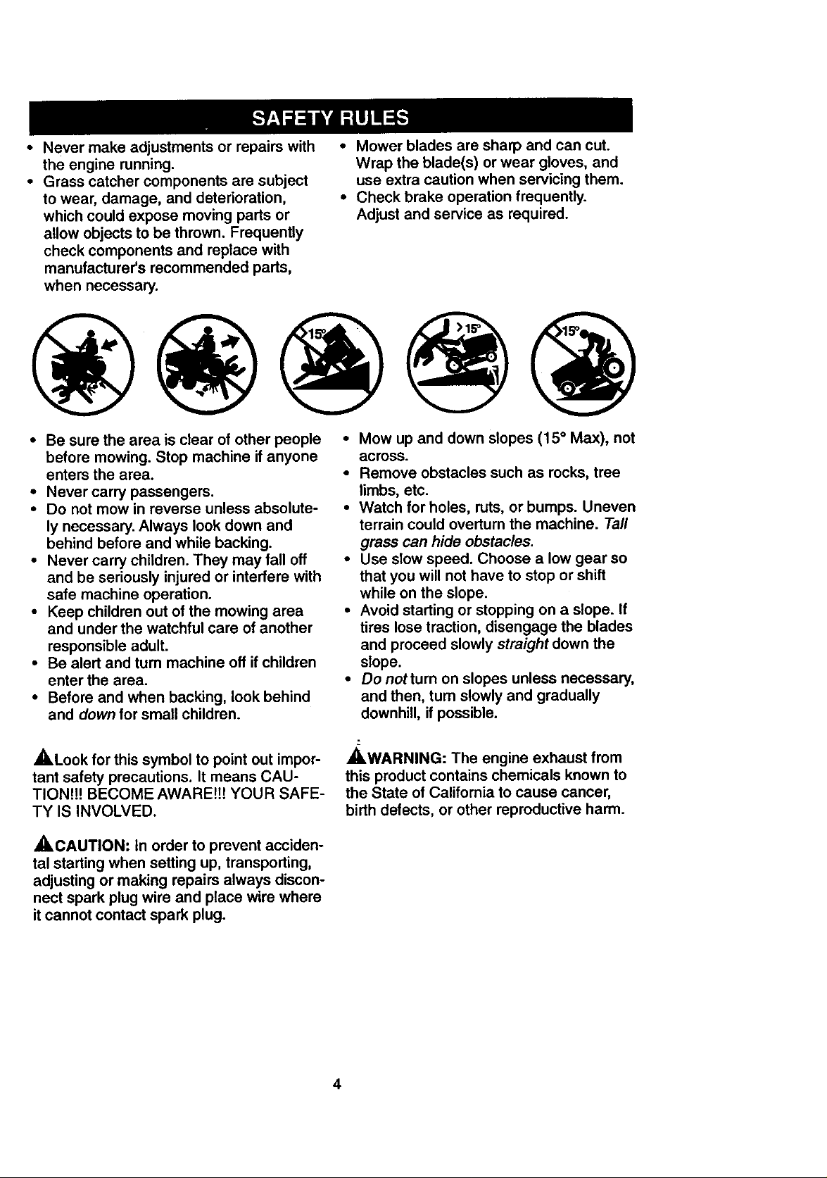
• Mow up and down slopes (15 ° Max), not
across.
• Remove obstacles such as rocks, tree
limbs, etc.
• Watch for holes, ruts, or bumps. Uneven
terrain could overturn the machine. Taft
grass can hide obstacles.
• Use slow speed. Choose a low gear so
that you will not have to stop or shift
while on the slope.
• Avoid starting or stopping on a slope. If
tires lose traction, disengage the blades
and proceed slowly straight down the
slope.
• Donotturnonslopesunlessnecessary,
and then, turn slowly and gradually
downhill, if possible.
_[ILWARNING: The engine exhaust from
this product contains chemicals known to
the State of California to cause cancer,
birth defects, or other reproductive harm.
4
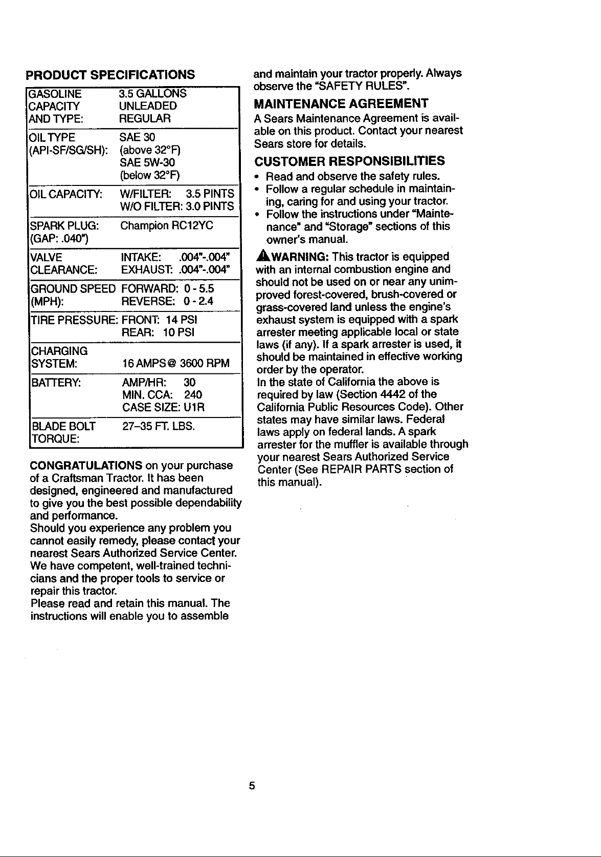
PRODUCT SPECIFICATIONS
GASOLINE 3.5 GALLONS
CAPACITY UNLEADED
AND TYPE: REGULAR
OILTYPE SAE 30
API-SF/SG/SH): (above 32°F)
SAE 5W-30
(below 32°F)
OIL CAPACITY: W/FILTER: 3.5 PINTS
W/O FILTER: 3.0 PINTS
_PARK PLUG:
'GAP: .040")
VALVE
;LEARANCE:
GROUND SPEED FORWARD: 0 - 5.5
(MPH): REVERSE: 0 - 2.4
rIRE PRESSURE: FRONT: 14 PSI
CHARGING
SYSTEM: 16 AMPS @ 3600 RPM
BATTERY: AMP/HR: 30
BLADE BOLT 27-35 FT. LBS.
TORQUE:
CONGRATULATIONS on your purchase
of a Craftsman Tractor. It has been
designed, engineered and manufactured
to give you the best possible dependability
and performance.
Should you experience any problem you
cannot easily remedy, please contact your
nearest Sears Authorized Service Center.
We have competent, well-trained techni-
cians and the proper tools to service or
repair this tractor.
Please read and retain this manual. The
instructions will enable you to assemble
Champion RC12YC
INTAKE: .004"-.004"
EXHAUST: .004"-.004"
REAR: 10 PSI
MIN. CCA: 240
CASE SIZE: U1R
and maintain your tractor properly.Always
observe the =SAFETY RULES".
MAINTENANCE AGREEMENT
A Sears Maintenance Agreement is avail-
able on this product. Contact your nearest
Sears store for details.
CUSTOMER RESPONSIBILITIES
• Read and observe the safety rules.
• Follow a regular schedule in maintain-
ing, caring for and using your tractor.
• Follow the instructions under =Mainte-
nance" and =Storage" sections of this
owner's manual.
,_.WARNING: This tractor is equipped
with an internal combustion engine and
should not be used on or near any unim-
proved forest-covered, brush-covered or
grass-covered land unless the engine's
exhaust system is equipped with a spark
arrester meeting applicable local or state
laws (if any). If a spark arrester is used, it
should be maintained in effective working
order by the operator.
In the state of California the above is
required by law (Section 4442 of the
California Public Resources Code). Other
states may have similar laws. Federal
laws apply on federal lands. A spark
arrester for the muffler is available through
your nearest Sears Authorized Service
Center (See REPAIR PARTS section of
this manual).
5
_eLOJdllll_ _t_ll_'l[oJ l: V_,I-"I JiVAVl,.1r,!_11_/:_LI,J_
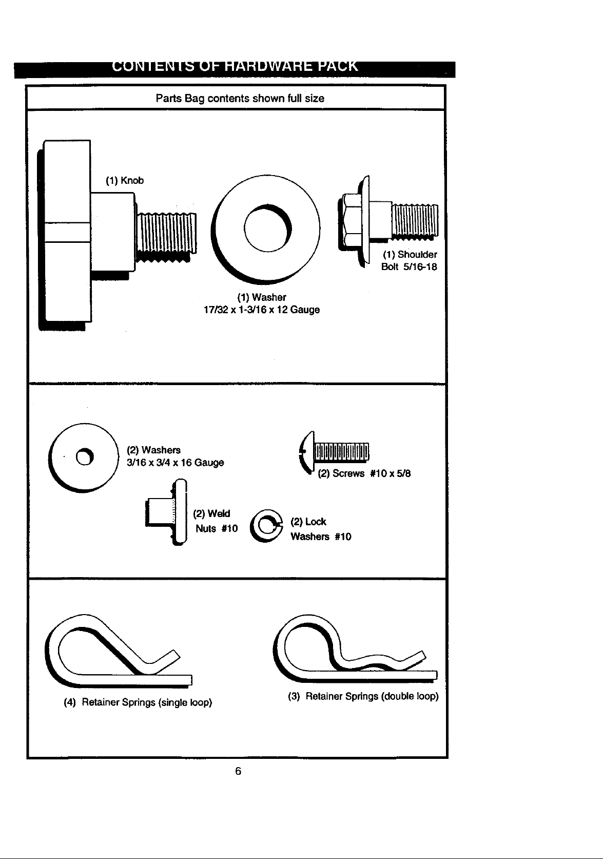
Parts Bag contents shown full size
(1) Knob
(1) Washer
17/32 x 1-3/16 x 12 Gauge
(1) Shoulder
Bolt 5/16-18
(2) Washers
3/16 x 3/4 x 16 Gauge
(2) Weld
Nuts #10
(4) Retainer Springs (singleloop)
_#10 x 5/8
(2) Lock
Washers #10
(3) Retainer Springs (double loop)
6
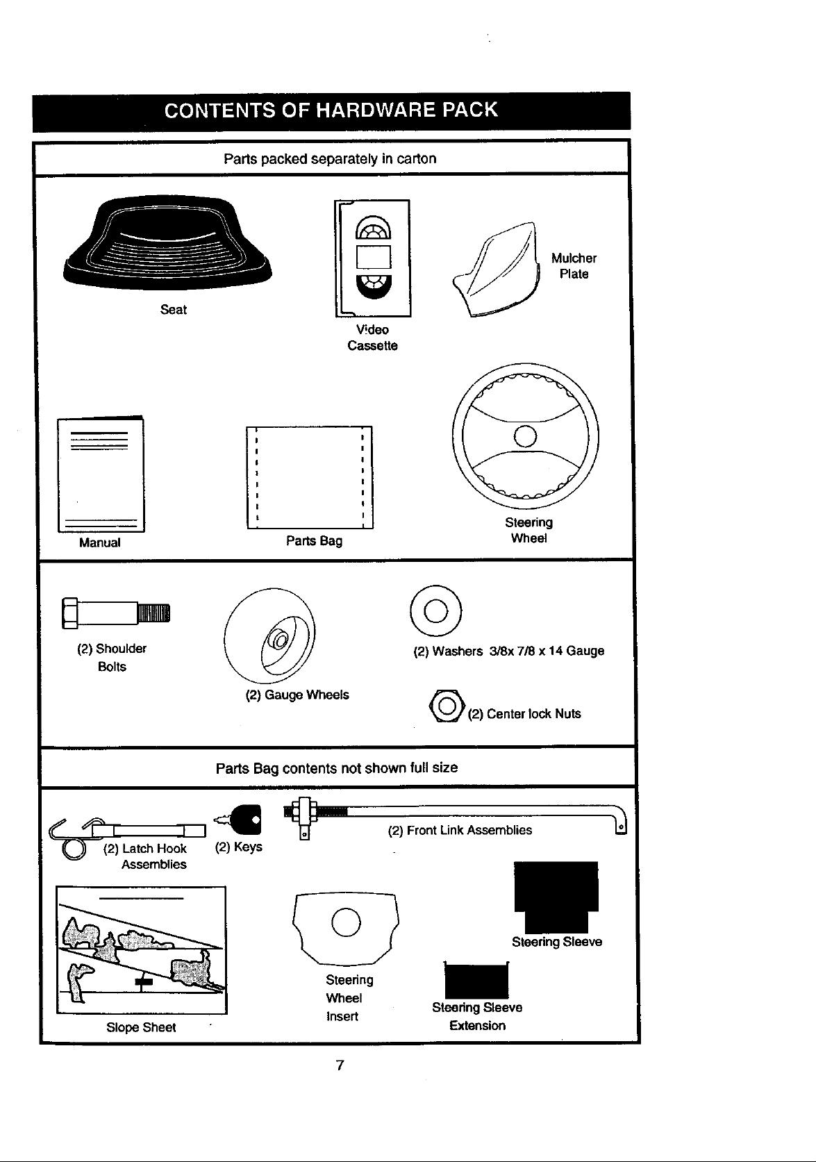
Partspackedseparatelyincarton
J
Manual
(2) Shoulder
Bolts
B
Seat
I
I
!
|
I
I
I
L
n
Parts Bag
D
Video
Cassette
I
I
Mulcher
Plate
Steering
Wheel
©
(2) Washers 3/8x 7/8 x 14 Gauge
(2) Gauge Wheels
Parts Bag contents not shown full size
%__, ,,_ _"
(2) Latch Hook (2) Keys
Assemblies
Slope Sheet
Steering
Wheel
Insert
Q(2) CenterlockNuts
(2) Front Link Assemblies
SteedngSleeve
Steering Sleeve
Extension
Your new tractor has been assembled at the factory with exception of those parts left
unassembled for shipping purposes. To ensure safe and proper operation of your tractor
all parts and hardware you assemble must be tightened securely. Use the correct tools
as necessary to insure proper tightness. Review the video cassette before you begin.
TOOLS REQUIRED FOR
ASSEMBLY
A socket wrench set will make assembly
easier. Standard wrench sizes you need
are listed below.
(1) 3/4" wrench (1) 3/4" Socket w/
(2) 1/2" wrench drive rachet
(1) Utility knife (1) Phillips Screw-
(1) Pliers driver
(1) Tire pressure gauge
When right or left hand is mentioned in
this manual, it means, from your point of
view, when you are in the operating posi-
tion (seated behind the steering wheel).
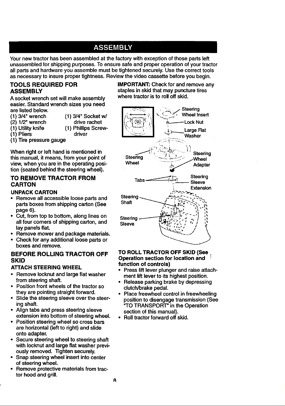
IMPORTANT: Check for and remove any
staples in skid that may puncture tires
where tractor is to roll oft skid.
_:_ _ Steering
--- . Wheel Insert
TO REMOVE TRACTOR FROM
CARTON
UNPACK CARTON
• Remove all accessible loose parts and
parts boxes from shipping carton (See
page 6).
• Cut, from top to bottom, along lines on
all four comers of shipping carton, and
lay panels flat.
• Remove mower and package materials.
• Check for any additional loose parts or
boxes and remove.
BEFORE ROLLING TRACTOR OFF
SKID
ATTACH STEERING WHEEL
• Remove Iocknut and large flat washer
from steering shaft.
• Position front wheels of the tractor so
they are pointing straight forward.
• Slide the steering sleeve over the steer-
ing shaft.
• Align tabs and press steering sleeve
extension into bottom of steering wheel.
• Position steering wheel so cross bars
are horizontal (left to right) and slide
onto adapter.
• Secure steering wheel to steering shaft
with Iocknut and large fiat washer previ-
ously removed. Tighten securely.
• Snap steering wheel insert into center
of steering wheel.
• Remove protective materials from trac-
tor hood and grill.
Steering ,,
Sleeve ' '
TO ROLL TRACTOR OFF SKID (See.
Operation section for location and
function of controls)
• Press lift lever plunger and raise attach-
ment lift lever to its highest position.
• Release parking brake by depressing
clutch/brake pedal.
• Place freewheel control in freewheeling
position to disengage transmission (See
"TO TRANSPORT" in the Operation
section of this manual).
• Roll tractor forward off skid.
R
HOW TO SET UP YOUR TRACTOR
CHECK BATTERY
• Lift hood to raised position.
• If this battery is put into service after
month and year indicated on label (label
located between terminals) charge bat-
tery for minimum of one hour at 6-10
amps. (See "BATTERY" in Maintenance
section of this manual for charging
instructions).
.--:._," . ......
,,-: ...... ." :._.. /Label
_t
fl
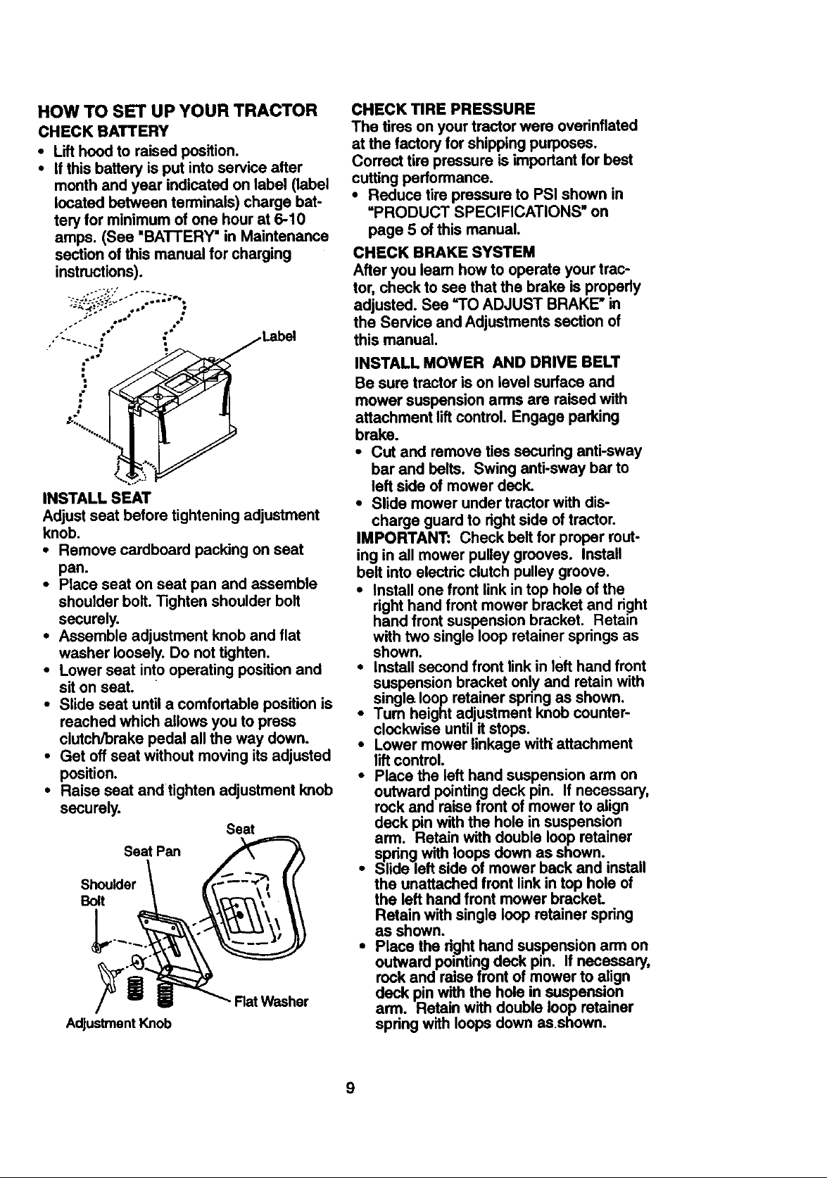
INSTALL SEAT
Adjustseat before tightening adjustment
knob.
• Remove cardboard packing on seat
pan.
• Place seat on seat pan and assemble
shoulder bolt.Tighten shoulder bolt
securely.
• Assemble adjustment knob and flat
washer loosely.Do not tighten.
• Lower seat into operating positionand
sit on seat.
• Slide seat until a comfortable position is
reached which allows you to press
clutch/brake pedal all the way down.
• Get off seat without moving its adjusted
position.
• Raise seat and tighten adjustment knob
securely.
Seat
Seat Pan
Shoulder
Bolt
Rat Washer
Adjustment Knob
CHECK TIRE PRESSURE
The tires on your tractor were ovednflated
at the factory for shipping purposes.
Correct tire pressure is important for best
cutting performance.
• Reduce tire pressure to PSI shown in
"PRODUCT SPECIFICATIONS" on
page 5 of this manual.
CHECK BRAKE SYSTEM
After you leam how to operate your trac-
tor, check to see that the brake is properly
adjusted. See =TO ADJUST BRAKE" in
the Service and Adjustments section of
this manual.
INSTALL MOWER AND DRIVE BELT
Be sure tractor is on level surface and
mower suspension arms are raised with
attachment lift control. Engage parking
brake.
• Cut and remove ties securing anti-sway
bar and belts. Swing anti-sway bar to
left side of mower deck.
• Slide mower under tractor with dis-
charge guard to right side of tractor.
IMPORTANT: Check belt for proper rout-
ing in all mower pulley grooves. Install
belt into electric clutch pulley groove.
• Install one front link in top hole of the
right hand front mower bracket and right
hand front suspension bracket. Retain
with two single loop retainer springs as
shown.
• Install second front link in left hand front
suspension bracket only and retain with
single loop retainer spring as shown.
•Tum height adjustment knob counter-
clockwise untilit stops.
• Lower mower linkage with_attachment
liftcontrol.
• Place the left hand suspension arm on
outward pointingdeck pin. If necessary,
rock and raise front of mower to align
deck pin withthe hole in suspension
arm. Retain with double loop retainer
spring with loops down as shown.
• Slide left side of mower back and install
the unattached front link in top hole of
the left hand frontmower brackeL
Retain with single loop retainer spring
as shown.
• Place the righthand suspension arm on
outward pointingdeck pin. If necessary,
rock and raise front of mower to align
deck pin with the hole in suspension
arm. Retain with double loop retainer
spdng with loops down asshown.
9
• Connect anti-sway bar to chassis brack-
et under left footrest and retain with
double loop retainer spring.
• Turn height adjustment knob clockwise
to remove slackfrom mower suspen-
sion.
• Raise mower to highest position.
Assemble gauge wheels (See "TO
ADJUST GAUGE WHEELS in the
Operation section of this manual).
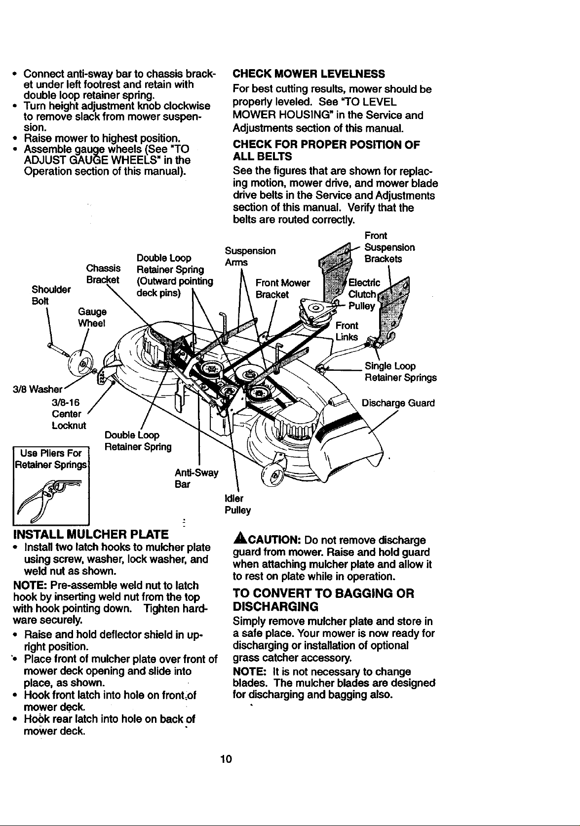
Double Loop
Chassis Retainer Spring
Bracket (Outward pointing
Shoulder deck pins)
Bolt
CHECK MOWER LEVELNESS
For best cutting results, mower should be
properly leveled. See =TO LEVEL
MOWER HOUSING" in the Service and
Adjustments section of this manual.
CHECK FOR PROPER POSITION OF
ALL BELTS
See the figures that are shown for replac-
ing motion, mower drive, and mower blade
drive belts in the Service and Adjustments
section of this manual. Verify that the
belts are routed correctly.
Front
Suspension Suspension
Arms Brackets
Front Mower
Bracket
3/8-16
Center
Locknut
Double Loop
Use Pliers For
Retainer Springs
Retainer Spring
Anti-Sway
Bar
INSTALL MULCHER PLATE
• Install two latchhooks to mulcher plate
using screw, washer, lock washer, and
weld nut as shown.
NOTE: Pro-assemble weld nut to latch
hook by inserting weld nut from the top
with hook pointingdown. Tighten hard-
ware securely.
• Raise and hold deflector shield in up-
right position.
'• Place front of mulcher plate over front of
mower deck opening and slide into
place, as shown.
• Hook front latch into hole on front=of
mower deck.
• Hook rear latch into hole on back of
mower deck.
Retainer Springs
Discharge Guard
Idler
Pulley
ACAUTION: Do not remove discharge
guard from mower. Raise and hold guard
when attaching mulcher plate and allow it
to rest on plate while in operation.
TO CONVERT TO BAGGING OR
DISCHARGING
Simply remove mulcher plate and store in
a safe place. Your mower is now ready for
discharging or installation of optional
grass catcher accessory.
NOTE: It is not necessary to change
blades. The mulcher blades are designed
for discharging and bagging also.
10

Weld
Nut
Latch
Weld Nut
Lock
Washer
Deflector
Shield
Hook Points
Latch
Lock
Washer
Latch
WHILE LEARNING HOW TO USE YOUR
TRACTOR, PAY EXTRA ATTENTION TO
THE FOLLOWING IMPORTANT ITEMS:
,/ Engine oil is at proper level.
/ Fuel tank is filledwith fresh, clean,
regular unleaded gasoline.
/ Become familiar with all controls - their
locationand function. Operate them
before you start the engine.
,/ Be sure brake system is in safe operat-
ing condition.
/ It is important to purge the transmis-
sion before operating your tractor for
the first time.Follow proper starting
and transmission purging instructions
(See "TO START ENGINE" and
"PURGE TRANSMISSION" in the Op-
eration section ofthis manual).
v"CHECKLIST
PLEASE REVIEW THE FOLLOWING
CHECKLIST:
v' All assembly instructions have been
completed.
v' No remaining loose parts incarton.
v' Battery is properly prepared and
charged. (Minimum 1 hour at 6 amps).
v' Seat isadjusted comfortably and
tightened securely.
!/ All tires are properly inflated. (For
shipping purposes_the tires were
overinflated at the factory).
i,,' Be sure mower deck is propedy leveled
side-to-sideJfront-to-rear for best
cutting results. ('Rres must be properly
inflated for leveling).
v' Check mower and drive belts. Be sure
they are routed properly around pulleys
and inside all belt keepers.
v' Check wiring. See that all connections
are still secure and wires are properly
clamped.
v' Before drivingtractor, be sure free-
wheel control is in ddve position.
11
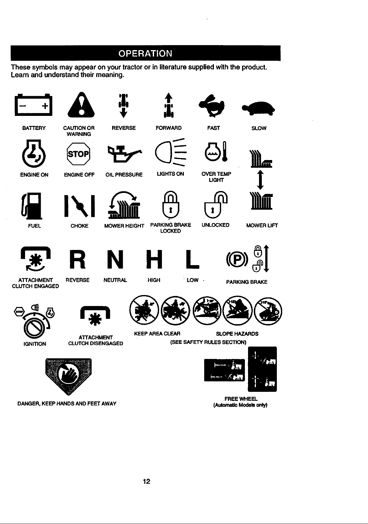
Thesesymbolsmayappearonyourtractororin literaturesuppliedWiththeproduct.
Learnandunderstandtheirmeaning.
BATTERY CAUTION OR REVERSE FORWARD FAST SLOW
WARNING
ENG,NEONENG,NEOFFOILFRE=U"E°GNTSCHOV_,?E_P1'
FUEL CHOKE MOWER HEIGHT PARKING BRAKE UNLOCKED MOWER UFT
LOCKED
N H L (®)
ATTACHMENT REVERSE NEUTRAL HIGH ' LOW - PARKINGBRAKE
CLUTCH ENGAGED
ATTACHMENT KEEP AREA CLEAR SLOPE HAZARDS
IGNITION CLUTCH DISENGAGED (SEE SAFETY RULES SECTION)
DANGER. KEEP HANDS AND FEET AWAY
FREEWHEEL
(AuiomaticModelsonly)
12
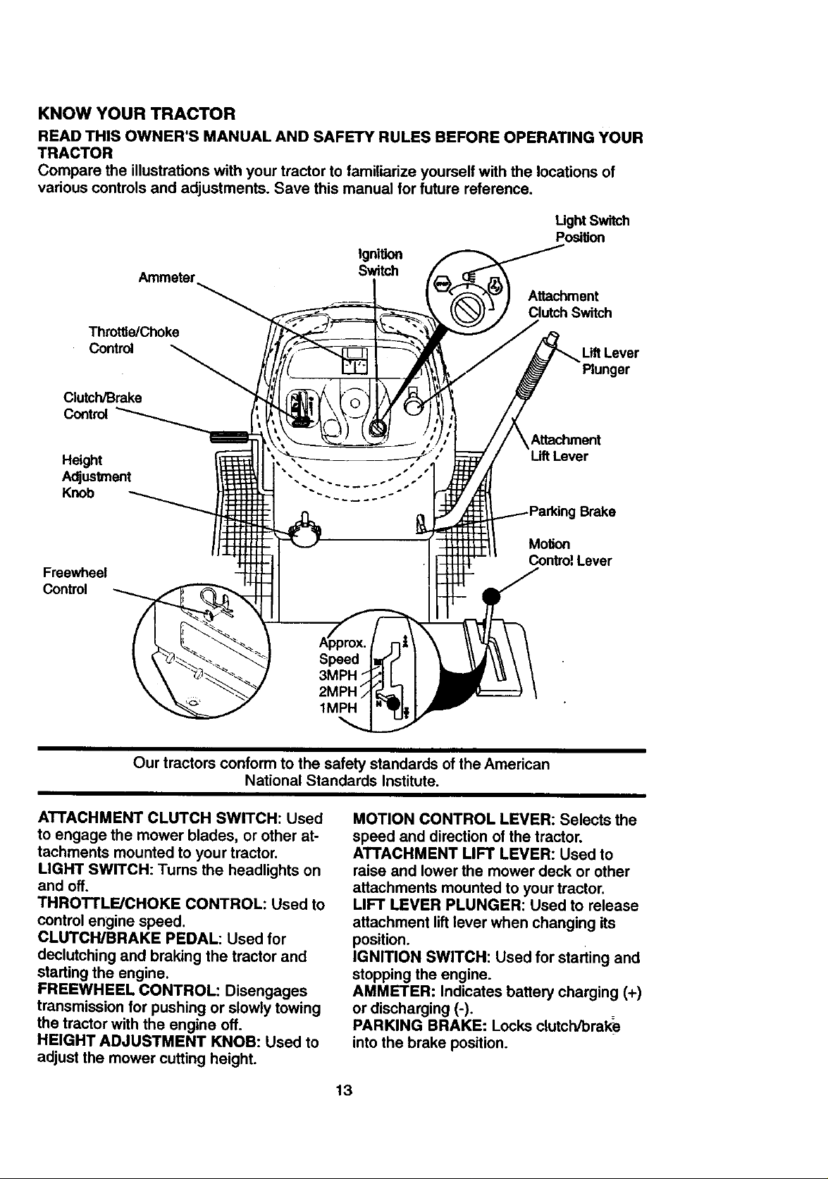
KNOW YOUR TRACTOR
READTHISOWNER'SMANUALANDSAFETYRULESBEFOREOPERATINGYOUR
TRACTOR
Comparetheillustrationswithyourtractortofamiliarizeyourselfwiththelocationsof
variouscontrolsandadjustments.Savethismanualforfuturereference.
Ught Switch
Position
Ignition
Ammeter
Throttle/Choke
Control
Clutch/Brake
Control
Switch
Attachment
Clutch Switch
Lift Lever
Plunger
Attachment
Lift Lever
Brake
Freewheel
Control
Our tractors conform to the safety standards of the American
National Standards Institute.
ATTACHMENT CLUTCH SWITCH: Used
to engage the mower blades, or other at-
tachments mounted to your tractor.
LIGHT SWITCH: Turns the headlights on
and off.
THROTTLE/CHOKE CONTROL: Used to
control engine speed.
CLUTCH/BRAKE PEDAL: Used for
declutching and braking the tractor and
starting the engine.
FREEWHEEL CONTROL: Disengages
transmission for pushing or slowly towing
the tractor with the engine off.
HEIGHT ADJUSTMENT KNOB: Used to
adjust the mower cutting height.
Motion
Control,Lever
Speed
3MPH 1
2MPH
1MPH
MOTION CONTROL LEVER: Selects the
speed and direction of the tractor.
ATTACHMENT LIFT LEVER: Used to
raise and lower the mower deck or other
attachments mounted to your tractor.
LIFT LEVER PLUNGER: Used to release
attachment lift lever when changing its
position.
IGNITION SWITCH: Used for starting and
stopping the engine.
AMMETER: Indicates battery charging (+)
or discharging (-).
PARKING BRAKE: Locks clutch/brake
into the brake position.
13
eyes, which can result in severe eye damage. Always wear safety glasses
or eye shields while operating your tractor or performing any adjustments or
!_ he operation of any tractor can result in foreign objects thrown into the
HOW TO USE YOUR TRACTOR NOTE: Failure to move throttle control to
Your tractor is equipped with an operator slow position and allowing engine to idle
presence sensing switch. When engine is before stopping may cause engine to
running, any attempt by the operator to "backfire".
leave the seat without first setting the • Turn ignition key to "OFF" position and
parking brake will shut off the engine, remove key. Always remove key when
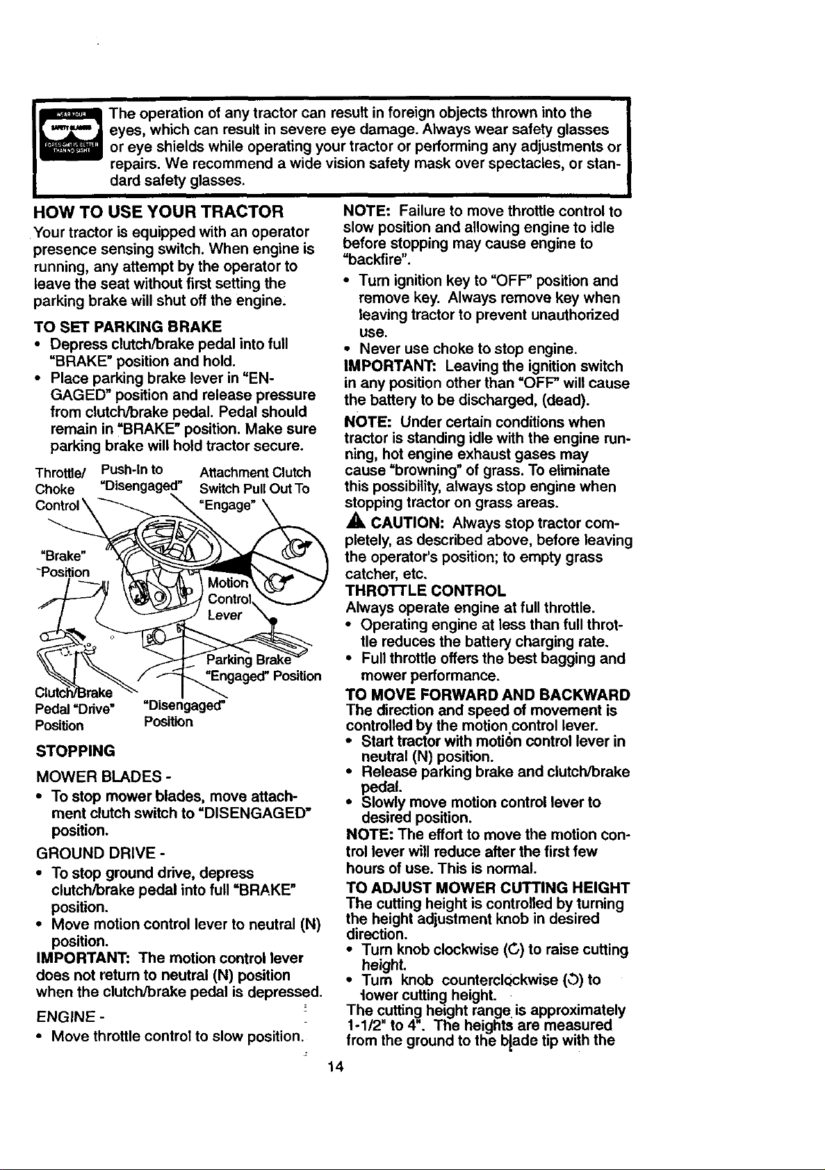
TO SET PARKING BRAKE use.
• Depress clutch/brake pedal into full • Never use choke to stop engine.
"BRAKE" position and hold. IMPORTANT: Leaving the ignition switch
• Place parking brake lever in "EN- in any position other than "OFF" will cause
GAGED" position and release pressure the battery to be discharged, (dead).
from clutch/brake pedal. Pedal should NOTE: Under certain conditions when
remain in =BRAKE" position. Make sure
parking brake will hold tractor secure, tractor is standing idle with the engine run-
Throffie/ Push-In to Attachment Clutch cause =browning" of grass. To eliminate
Choke Switch Pull Out To this possibility, always stop engine when
"Brake" the operator's position; to empty grass
-Position catcher, etc.
Pedal =Drive" "Disengaged" The direction and speed of movement is
Position Position controlled by the motion.control lever.
STOPPING neutral (N) position.
MOWER BLADES - • Release parking brake and clutch/brake
• To stop mower blades, move attach- ° Slowly move motion control lever to
merit clutch switch to "DISENGAGED" desired position.
position. NOTE: The effort to move the motion con-
GROUND DRIVE - trol lever will reduce after the first few
• To stop ground drive, depress hours of use. This is normal.
clutch/brake pedal into full "BRAKE" TO ADJUST MOWER CUTTING HEIGHT
position. The cutting height is controlled by turning
• Move motion control lever to neutral (N) the height adjustment knob in desired
position.
IMPORTANT: The motion control lever •Tum knob clockwise (G) to raise cutting
does not return to neutral (N) position •Tum knob counterclQckwise (O) to
when the clutch/brake pedal is depressed, tower cutting height.
ENGINE - _ The cutting height range is approximately
• Move throttle control to slow position, from the ground to the b{ade tip with the
repairs. We recommend a wide vision safety mask over spectacles, or stan-
dard safety glasses.
leaving tractor to prevent unauthorized
ning, hot engine exhaust gases may
"Engage" stopping tractor on grass areas.
A, CAUTION: Always stop tractor com-
pletely, as described above, before leaving
THRO'n'LE CONTROL
Always operate engine at full throttle.
• Operating engine at less than full throt-
tle reduces the battery charging rate.
• Full throttle offers the best bagging and
"Engaged" Position mower performance.
TO MOVE FORWARD AND BACKWARD
• Start tractor with motion control lever in
pedal.
direction.
height.
1-1/2" to 4". The heights are measured
14
engine not running. These heights are ap-
proximate and may vary depending upon
soil conditions, height of grass and types
of grass being mowed.
• The average lawn should be cut to
approximately 2-112 inches during the
cool season and to over 3 inches during
hot months. For healthier and better
looking lawns, mow often and after
moderate growth.
• For best cutting performance, grass
over 6 inches in height shouldbe
mowed twice. Make the first cut rela-
tively high; the second to desired
height.
TO ADJUST GAUGE WHEELS
Gauge wheels are properly adjusted
when they are slightly off the ground when
mower is at the desired cutting height in
operating position. Gauge wheels then
keep the dock in proper position to help
prevent scalping in most terrain condi-
tions.
• Adjust gauge wheels with tractor on a
flat level surface.
• Adjust mower to desired cutting height
(See "TO ADJUST MOWER CUTTING
HEIGHF in the Operation section of
this manual).
• With mower in desired height of cut po-
sition, gauge wheels should be assem-
bled so they are slightly off the ground.
Install gauge wheel in appropriate hole
with shoulder bolt, 3/8 washer, and 3/8-
16 Iocknut and tighten securely.
• Repeat for opposite side installing
gauge wheel in same adjustment hole.
Mounting.
Bracket
3/8-16
Locknut Shoulder Bolt
3/8 Washer ._augeWheel
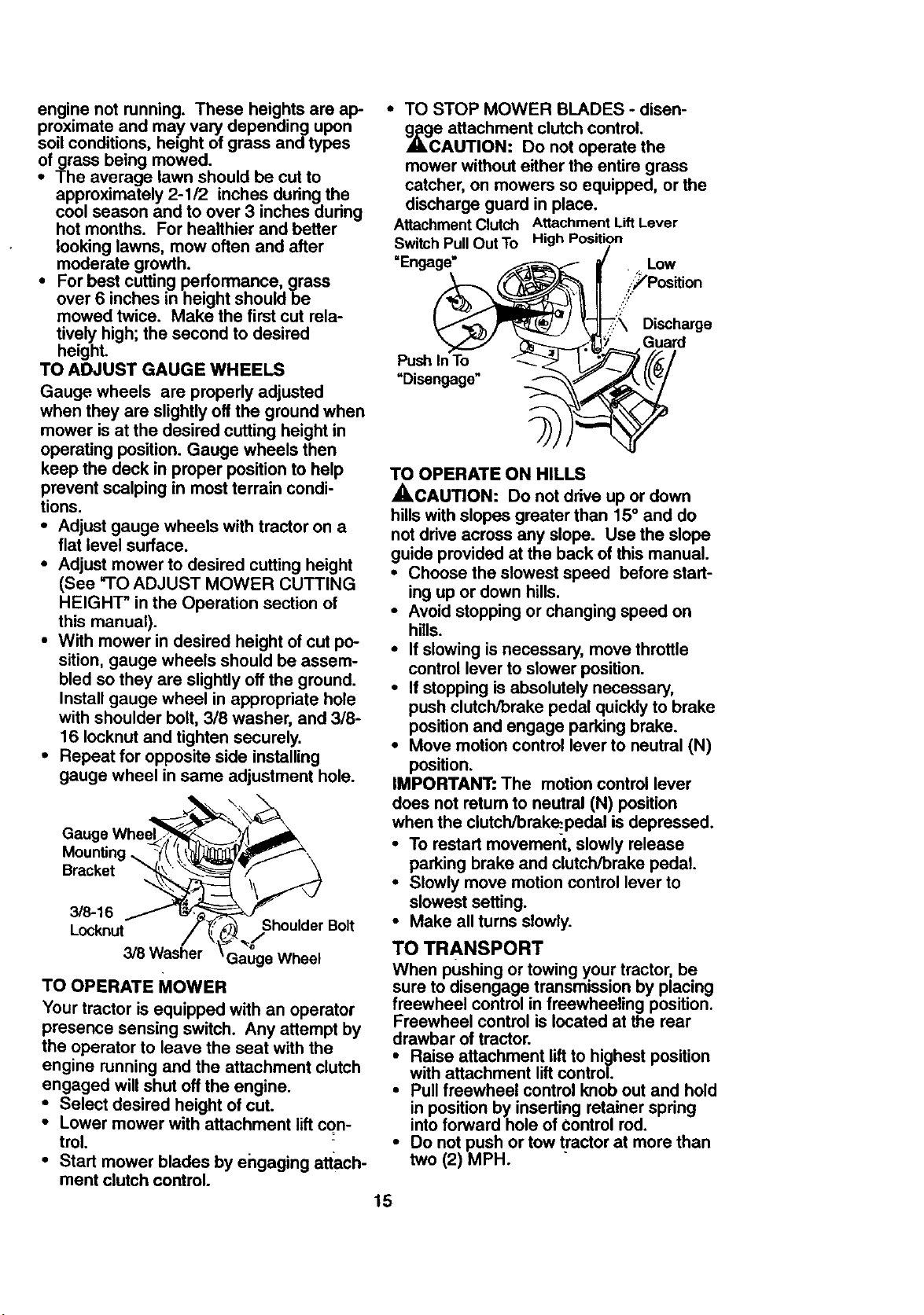
TO OPERATE MOWER
Your tractor is equipped with an operator
presence sensing switch. Any attempt by
the operator to leave the seat with the
engine running and the attachment clutch
engaged will shut off the engine.
• Select desired height of cut.
• Lower mower with attachment lift con-
trol.
• Start mower blades by engaging attach-
ment clutch control.
• TO STOP MOWER BLADES - disen-
g_gce attachment clutch control.
AUTION: Do not operate the
mower without either the entire grass
catcher, on mowers so equipped, or the
discharge guard in place.
Attachment Clutch Attachment Lift Lever
Switch PullOut To High Position
.;::_'Position
Y
=Enga_ Low
- "\ Discharge
_/ Guard
=Disengage" .._ ,_'
Push InTo _-._"_ _._
TO OPERATE ON HILLS
_,CAUTION: Do not drive up or down
hills with slopes greater than 15 ° and do
not drive across any slope. Use the slope
guide provided at the back of this manual.
• Choose the slowest speed before start-
ing up or down hills.
• Avoid stopping or changing speed on
hills.
• If slowing is necessary, move throttle
control lever to slower position.
• If stopping is absolutely necessary,
push clutch/brake pedal quickly to brake
position and engage parking brake.
• Move motion control lever to neutral (N)
position.
IMPORTANT: The motion control lever
does not retum to neutral (N) position
when the clutch/brak_pedal is depressed.
• To restart movement, slowly release
parking brake and clutch/brake pedal.
• Slowly move motion control lever to
slowest setting.
• Make all turns slowly.
TO TRANSPORT
When pushing or towing your tractor, be
sure to disengage transmission by placing
freewheel control in freewheeling position.
Freewheel control is located at the rear
drawbar of tractor.
• Raise attachment lift to highest position
with attachment lift control.
• Pull freewheel control knob out and hold
in position by inserting retainer spring
into forward hole of Control rod.
• Do not push or tow tractor at more than
two (2) MPH. -
15

• To reengage transmission, reverse
above procedure.
NOTE: To protect hood from damage when
transporting your tractor on a truck or a
trailer, be sure hood is closed and secured
to tractor. Use an appropriate means of
tying hood to tractor (rope, cord, etc.).
TOWING CARTS AND OTHER ATTACH-
MENTS
Tow only the attachments that are recom-
mendedby and comply with specifications
of the manufacturer of your tractor. Use
common sense when towing. Too heavy of
a load, while on a slope, is dangerous.
Tires can lose traction with the ground and
cause you to lose control of your tractor.
BEFORE STARTING THE ENGINE
CHECK ENGINE OIL LEVEL
• The engine in your tractor has been
shipped, from the factory, already filled
with summer weight oil.
• Check engine oil with tractor on level
ground.
• Unthread and remove oil fill cap/dip-
stick; wipe oil off. Reinsert the dipstick
into the tube and rest oil fill cap on the
tube. Do not thread the cap onto the
tube. Remove and read oil level. If nec-
essary, add oil until =FULL" mark on
dipstick is reached. D_enot overfill.
• For cold weather operation you should
change oil for easier starting (See =OIL
VISCOSITY CHART* in the Customer
Responsibilities section of this manual).
• To change engine oil, see the Customer
Responsibilities section in this manual.
ADD GASOLINE
• Fill fuel tank. Use fresh, clean, regular
unleaded gasoline with a minimum of 87
octane. (Use of leaded gasoline will
increase carbon and lead oxide
deposits and reduce valve life). Do not
mix oil with gasoline. Purchase fuel in
quantities that can be used within 30
days to assure fuel freshness.
IMPORTANT: When operating in tempera-
tures below 32°F(0°C), use fresh, clean
winter grade gasoline to Ipelp insure good
cold weather starting. .
!
_,WARNING: Experience indicates that
alcohol blended fuels (called gasohol or
using ethanol or methanol) can attract
moisture which leads to separation and
formation of acids during storage. Acidic
gas can damage the fuel system of an
engine while in storage. To avoid engine
problems, the fuel system should be emp-
tied before storage of 30 days or longer.
Drain the gas tank, start the engine and let
it run until the fuel lines and carburetor are
empty. Use fresh fuel next season. See
Storage Instructions for additional informa-
tion. Never use engine or carburetor
cleaner products in the fuel tank or perma-
nent damage may occur.
,_CAUTION: Fill to bottom of gas tank
filler neck. Do not overfill. Wipe off any
spilled oil or fuel. Do not store, spill or use
gasoline near an open flame.
TO START ENGINE
When starting the engine for the first time
or if the engine has run out of fuel, it will
take extra cranking time to move fuel from
the tank to the engine.
• Be sure freewheel control is in the
transmission engaged position.
• Sit on seat in operating position,
depress clutch/brake pedal and set
parking brake.
• Place motion control lever in neutral (N)
position.
• Move attachment clutch to "DISEN-
GAGED" position.
• Move throttle control to choke position.
NOTE: Before starting, read the warm and
cold starting procedures below.
• Insert key into ignition and turn key
clockwise to =START* position and
release key as soon as engine starts.
Do not run starter continuously for more
than fifteen seconds per minute. If the
engine does not start after several
attempts, move throttle control to fast
position, wait a few minutes and try
again. If engine still does not start,
move the throttle control back to the
choke position and retry.
WARM WEATHER STARTING (50 ° F and
above)
• When engine starts, move the throttle
control to the fast position.
• The attachments and ground drive can
now be used. If the engine does not
accept the load, restart the engine and
allow it to warm up for one minute using
the choke as described above.
16
COLD WEATHER STARTING ( 50 ° F and
below)
• When engine starts, allow engine to run
with the throttle control in the choke
position until the engine runs roughly,
then move throttle control to fast posi-
tion. This may require an engine warm-
up pedod from several seconds to sev-
eral minutes, depending on the temper-
ature.
AUOTMATIC TRANSMISSION WARM UP
• Before ddving the unit in cold weather,
the transmission should be warmed up
as follows:
• Be sure the tractor is on level ground.
• Place the motion control lever in neutral.
Release the parking brake and let the
clutch/brake slowly return to operating
position.
• Allow one minute for transmission to
warm up. This can be done dudng the
engine warm up pedod.
• The attachments can also be used dur-
ing the engine warm-up period after the
transmission has been warmed up.
NOTE: At a high altitude (above 3000
feet) or in cold temperatures (below 32 F)
the carburetor fuel mixture may need to be
adjusted for best engine performance.
See "TO ADJUST CARBURETOR" in the
Service and Adjustments section of this
manual.
PURGE TRANSMISSION
,_CAUTION: Never engage or disen-
gage freewheel lever while the engine is
running.
To ensure proper operation and perfor-
mance, it is recommended that the trans-
mission be purged before operating tractor
for the first time. This procedure will
remove any trapped air inside the trans-
mission which may have developed during
shipping of your tractor.
IMPORTANT: Should your transmission
require removal for service or replace-
ment, it should be purged after reinstalla-
tion before operating the tractor.
• Place tractor safely on level surface with
engine off and parking brake set.
• Disengage transmission by placing free-
wheel control in freewheeling position
(See "TO TRANSPORT" in this section
of manual).
• Sitting in the tractor seat, start engine.
After the engine is running, move throt-
tle control to slow position. With motion
control lever in neutral (N) position,
slowly disengage clutch/brake pedal.
• Move motion control lever to full forward
position and hold for five (5) seconds.
Move lever to full reverse position and
hold for five (5) seconds. Repeat this
procedure three (3) times.
NOTE: During this procedure there will be
no movement of ddve wheels. The air is
being removed from hydraulic drive sys-
tem.
• Move motion control lever to neutral (N)
position. Shut off engine and set parking
brake.
• Engage transmission by placing free-
wheel control in driving position (See
"TO TRANSPORT" in this section of
manual).
• Sitting in the tractor seat, start engine.
After the engine is running, move throt-
tle control to half (1/2) speed. With
motion c:ontrol lever in neutral (N) posi-
tion, slowly disengage clutch/brake
pedal.
• Slowly move motion control lever for-
ward; after the tractor moves approxi-
mately five (5) feet, slowly move motion
control lever to reverse position. After
the tractor moves approximately five (5)
feet return the motion control lever to
the neutral (N) position. Repeat this pro-
cedure with the motion control lever
three (3) times.
• Your tractor is now purged and ready for
normal operation.
17
MOWING TIPS
• Tire chains cannot be used when the
mower housing is attached to tractor.
• Mower should be properly leveled for
best mowing performance. See "TO
LEVEL MOWER HOUSING" in the
Service and Adjustments section of this
manual.
• The left hand side of mower should be
used for trimming.
• Drive so that clippings are discharged
onto the area that has been cut. Have
the cut area to the dght of the tractor.
This will result in a more even distribu-
tion of clippings and more uniform cut-
ting.
• When mowing large areas, start by turn-
ing to the dght so that clippings will dis-
charge away from shrubs, fences, drive-
ways, etc. After one or two rounds, mow
in the opposite direction making left
hand turns until finished.
• If grass is extremely tall, it should be
mowed twice to reduce load and possi-
ble fire hazard from dried clippings.
Make first cut relatively high; the second
to the desired height.
• Do not mow grass when it is wet. Wet
grass will plug mower and leave unde-
sirable clumps. Allow grass to dry
before mowing.
• Always operate engine at full throttle
when mowing to assure better mowing
performance and proper discharge of
material. Regulate ground speed by se-
lecting a low enough gear to give the
mower the best cutting performance as
well as the quality of cut desired.
• When operating attachments, select a
ground speed that will suit the terrain
and give best performance of the at-
tachment being used.
MULCHING MOWING TIPS
IMPORTANT: For best performance, keep
mower housing free of built-up grass and
trash. Clean after each use.
• The special mulching blade will recut
the grass clippings many times and
reduce them in size so that as they fall
onto the lawn they will disperse into the
grass and not be noticed. Also, the
mulched grass will biodegrade quickly
to provide nutdents for the lawn. Always
mulch with your highest engine (blade)
speed as this will provide the best recut-
ting action of the blades.
• Avoid cutting your lawn when it is wet.
Wet grass tends to form clumps and
interferes with the mulching action. The
best time to mow your lawn is the early
afternoon. At this time the grass has
dried and the newly cut area will not be
exposed to the direct sun.
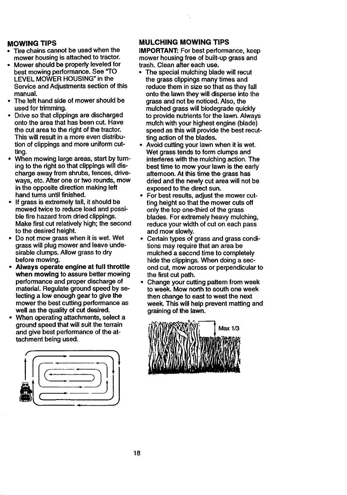
• For best results, adjust the mower cut-
ting height so that the mower cuts off
only the top one-third of the grass
blades. For extremely heavy mulching,
reduce your width of cut on each pass
and mow slowly.
• Certain types of grass and grass condi-
tions may require that an area be
mulched a second time to completely
hide the clippings. When doing a sec-
ond cut, mow across or perpendicular to
the first cut path.
• Change your cutting pattem from week
to week. Mow north to south one week
then change to east to west the next
week. This will help prevent matting and
graining of the lawn.
{__;_i_'_"_ Max 1/3
J
18
MA..TE.ANCESC.EDULE "
REGULAR SERVICE i,__._'/_._,,_,_'_ '' SERVICE DATES
Check Brake Operation _
Check Tire Pressure
Check Operator Presence and
T Interlock Systems If
R Check for Loose Fasteners V' 11_7 I tl_
CA SharperdReplace Mower Blades _4
T Lubrication Chart
0 Check Battery Level
R Clean Battery and Terminals ;If V'
Check Transaxle Cooling
Adjust Blade BaR(S) Tenslan V'_
Adjust Motion Drive Balt(s) Tension _s
Check Engine Oil Level V p
Change Engine Oil _.; V'
E Clean Air Filter
N CleanAir Screen
IG Inspect MuffierlSpark Attester V _
Replace Oil Filter (If equipped) _:
N Clean Engine Cooling Fins
Replace Spark Ping _ ;
Replace Air Filter Paper Cartridge 1_2
Replace Fuel Filter V _
I * Change more often when opemling under a he_ load or in high ambient temperatures. 5 - If equipped with ad_taMe systarn.
2 - Se_,ice more often when operating in dirty or dusty coc'_rdiorm. 6 ° Not required if equipped with maintenance4ree ban_
3 - If equip_ with oil liifer, change oil _ery 50 hours. 7 - Tightwn Iront axte pivo( bo/t to 35 ft,-Ib=, maximum.
4 ° Replace Medes more often when _ in sandy soil. DO not overl_ten.
GENERAL RECOMMENDATIONS
The warranty on this tractor does not cover
items that have been subjected to operator
abuse or negligence. To receive full value
from the warranty, operator must maintain
tractor as instructed in this manual. Some
adjustments will need to be made periodi-
cally to properly maintain your tractor.
All adjustments in the Service and
Adjustments section of this manual should
be checked at least once each season.
• Once a year you should replace the
spark plug, clean or replace air filter, and
check blades and belts for wear. A new
spark plug and clean air filter assure
proper air-fuel mixture and help your
engine run better and last longer.
BEFORE EACH USE
• Check engine oil level.
• Check brake operation.
• Check tire pressure.
• Check operator presence and interlock
systems for proper operation.
• Check for loose fasteners.
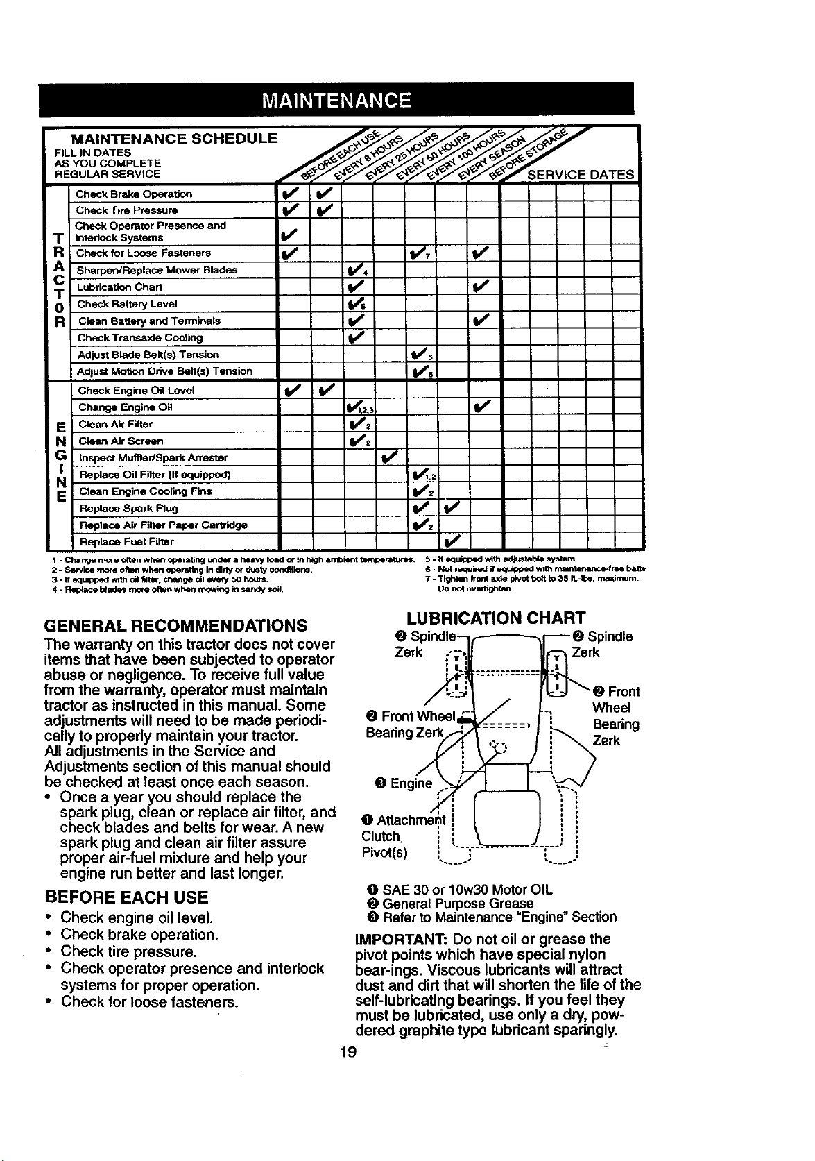
LUBRICATION CHART
Q ,indle
Zerk Zerk
O Front Wheel
Beadnq Bearing
Wheel
Zerk
O Engine
C, tch i i
Pivot(s) : : ,'. j
O SAE 30 or 10w30 Motor OIL
@ General Purpose Grease
O Refer to Maintenance "Engine_Section
IMPORTANT: Do not oil or grease the
pivot points which have special nylon
bear-ings. Viscous lubricants will attract
dust and dirt that will shorten the life of the
self-lubricating bearings. If you feel they
must be lubricated, use only a dry, pow-
dered graphite type lubricant sparingly.
19
=ront
TRACTOR
Alwaysobservesafetyruleswhenper-
forminganymaintenance.
BRAKEOPERATION
Iftractorrequiresmorethansix(6)feet
stoppingdistanceat highspeedin highest
gear,thenbrakemustbeadjusted.(See
=TO ADJUST BRAKE" in the Service and
Adjustments section of this manual).
TIRES
• Maintain proper air pressure in all tires
(See "PRODUCT SPECIFICATIONS"
on page 3 of this manual).
• Keep tires free of gasoline, oil, or insect
control chemicals which can harm rub-
ber.
• Avoid stumps, stones, deep ruts, sharp
objects and other hazards that may
cause tire damage.
NOTE: To seal tire punctures and prevent
flat tires due to slow leaks, tire sealant
may be purchased from your local parts
dealer. Tire sealant also prevents tire dry
rot and corrosion.
OPERATOR PRESENCE SYSTEM
Be sure that operator presence and inter-
lock systems are working properly. Ifyour
tractor does not function as described
below, repair the problem immediately.
• The engine should not start unless the
clutch/brake pedal is fully depressed
and attachment clutch control is in the
disengaged position.
• When the engine is running, any
attempt by the operator to leave the
seat without first setting the parking
brake should shut off the engine.
• When the engine is running and the
attachment clutch is engaged, any
attempt by the operator to leave the
seat should shut off the engine.
• The attachment clutch should never
operate unless the operator is in the
seat.
BLADE CARE
For best results mower blades must be
kept sharp. Replace bent or damaged
blades.
BLADE REMOVAL
• Raise mower to highest position to allow
access to blades.
• Remove hex bolt, lock washer and flat
washer securing blade.
• Install new or resharpened blade with
trailing edge up towards deck as shown.
IMPORTANT: To ensure proper assembly,
center hole in blade must align with star
on mandrel assembly.
• Reassemble hex bolt, lock washer and
flat washer in exact order as shown.
• TIghten bolt securely (27-35 Ft. Lbs.
torque).
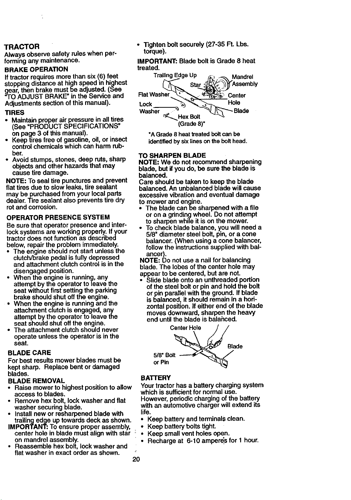
IMPORTANT: Blade bolt is Grade 8 heat
treated.
Trailing E Up Mandrel
Star
Flat Washer Center
Hole
Lock "_ _
Washer _F_._ Hex Bolt
(Grade 8)*
*A Grade 8 heat treated bolt can be
identifiedby six lines on the bolt head.
TO SHARPEN BLADE
NOTE: We do not recommend sharpening
blade, but if you do, be sure the blade is
balanced.
Care should be taken to keep the blade
balanced. An unbalanced blade will cause
excessive vibration and eventual damage
to mower and engine.
• The blade canbe sharpened with a file
or on a grinding wheel. Do not attempt
to sharpen while it is on the mower.
• To check blade balance, you will need a
5/8" diameter steel bolt, pin, or a cone
balancer. (When using a cone balancer,
follow the instructions supplied with bal-
ancer).
NOTE: Do not use a nail for balancing
blade. The lobes of the center hole may
appear to be centered, but are not.
• Slide blade onto an unthreaded portion
of the steel bolt or pin and hold the bolt
or pin parallel with the ground. If blade
is balanced, it should remain in a hori-
zontal position. If either end of the blade
moves downward, sharpen the heavy
end until the blade is balahced.
Center Hole
Blade
5/8" Bolt
or Pin
BATTERY
Your tractor has a battery charging system
which is sufficient for normal use.
However periodic charging of the battery
with an automotive charger will extend ts
life.
• Keep battery and terminals clean.
Keep battery bolts tight.
• Keep small vent holes open.
• Recharge at 6-10 amperds for I hour.
2O
 Loading...