

Craftsman 917259950 Owner’s Manual

917.259950
Western Auto
Operation and Service Instructions
Wizard Lawn Tractor
Stock Number
93-7159-2
Model Number
AYP7159A69
Factory Number
AYP7159A69
_ This product has a iow em!ssion engine which oper_ differ-
ently from previously built engines: Before you start the engine;
read and understand this Owner's Manual.
Thank you for purchasing an American-built product.

WESTERN AUTO TRACTOR LIMITED WARRANTY
AYP7159A69
Western Auto Supply Company warrants to the originalretailpurchaser that this product is free from defects in material or
workmanship and agrees to repair this product free of charge within these time periods from the date of purchase:
• 2 years, ifthe product is used for personal, family, or household use;
• 90 days, if the product is used for any other purpose such as commercial or rental use.
Excluded from this warranty are normal wear, maintenance, or mechanical adjustments which are not due to defects in
material orworkmanship. Consult your owner's manual for hbip tomaintainyour productor makemechanical adjustments. Products
whichhave been altered, misused,abused, or repaired byotherthana Western Auto-authorized or manufacturer-authorized service
facility are also excluded.
A rider or tractor battery which proves defective within 90 days will be replaced without charge. After 90 days but within 1
_,oearfrom the date of purchase, Western Auto will replace the battery for a charge of 1/12 of the current retail price of the battery
r each full month between the date of purchase and the date of return.
Engines or transaxles are warranted by the engine or transaxle manufacturer which gives its own 2 year warranty and
provides service through its authorized service facilities. See the engine or transaxle warrantyfor dataiis. Repair may be arranged
through padicipating Western Auto stores.
For repair service returnthis product with proof of purchase date to a padicipating Westem Auto store. This warranty gives
_ou specific legal rightsand you may have other rightsthat varyfrom stateto state. Ifdifficulty isencountered in having thiswarranty
onored, contact:
Westam Auto Supply Company
Consumer Affairs Section of the General Service Department
2107 Grand Avenue, Kansas City, Missouri 64108
Telephone: 816 346-4411
CONGRATULATIONS on your purchase of a new Tractor. It
has been designed, engineered and manufactured to give you
the best possible dependability and performance.
Should you experience any problem you cannot easily remedy,
please contact your nearest authorized service center. We
have competent, well-trained technicians and the proper tools
to service or repair this tractor.
Please read and retain this manual. The instructions will en-
able you to assemble and maintain your tractor properly. At-
ways observe the "SAFETY RULES".
PRODUCT SPECIFICATIONS
HORSEPOWER: 15.5
GASOLINE CAPACITY 2.0 GALLONS
AND TYPE: UNLEADED REGULAR
OIL TYPE (API-SF/SG): SAE 30 (above 32°F)
SAE 5W-30 (below 32°F)
OIL CAPACITY: W/FILTER: 3.5 PINTS
W/O FILTER: 3.0 PINTS
SPARK PLUG: CHAMPION RC12YC
3AP: .030")
VALVE CLEARANCE: INTAKE: .003" - .005"
EXHAUST: .605" - .007"
GROUND SPEED (MPH): FORWARD:
1st 1.13
2nd 1.44
3rd 2.33
4th 3.50
5th 4.46
6th 5.69
REVERSE: 1.75
TIRE PRESSURE: FRONT: 14 PSI
REAR: 10 PSI
CHARGING SYSTEM: 3 AMPS BATTERY
5 AMPS HEADLIGHTS
BATTERY: AMP/HR: 25
MIN. CCA: 190
CASE SIZE: U1R
BLADE BOLT TORQUE: 30-35 FT. LBS.
MODEL
NUMBER AYP 7159A69
SERIAL
NUMBER
DATE OF PURCHASE
THE MODEL AND SERIAL NUMBERS WILL BE FOUND ON A
PLATE UNDER THE SEAT.
YOU SHOULD RECORD BOTH SERIAL NUMBER AND DATE OF
PURCHASE AND KEEP IN A SAFE PLACE FOR FUTURE REFER-
ENCE.
Optional Western Auto Model
Accessory Stock No. No.
Grass Catcher 95-1031-4 C42
48" Snow Blade 95-2549-4F LBD48
42" Snow Thrower 95-2626-0F LSB42
CUSTOMER RESPONSIBILITIES
Read and observe the safety rules.
Follow a regular schedule in maintaining, caring for anc
using your tractor.
Follow the instructions under the "Customer Responsibili.
ties" and "Storage" sections of this owner's manual.
WARNING: This tractorisequipped with an internal combustior
engine and should not be used on or near any unimproved forest
covered, brush-covered or grass-covered land unless the engine'_
exhaust system is equipped with a spark arrester meeting appii
cable local or state laws (if any). If a spark arrester is used, I
should be maintained in effective working order by the operate,
In the state of California the above is required by law (Sectio_
4442 of the California Public Resources Code). Other states ma'
have similar laws. Federal laws apply on federal lands.
2
SAFETY RULESSafe Operation Practices for Ride-On Mowers ,_
IMPORTANT: THIS CUTTING MACHINE IS CAPABLE OF AMPUTATING HANDS AND FEET AND THROWING OBJECTS.
FAILURE TO OBSERVE THE FOLLOWING SAFETY INSTRUCTIONS COULD RESULT IN SERIOUS INJURY OR DEATH.
I= GENERAL OPERATION
Read, understand, and follow all instructionsin the manual
and on the machine before starting.
Only allow responsible adults, who are familiar with the
instructions, to operate the machine.
Clear the area of objects such as rocks, toys, wire, etc.,
which could be picked up and thrown by the blade.
Be sure the area is clear ofotherpeople before mowing. Stop
machine if anyone enters the area,
Never carry passengers.
Do not mow in reveree unless absolutely necessary. Always
look down and behind before and while backing.
Be aware of the mower discharge direction and do not point
it at anyone. Do not operate the mower without either the
entire grasscatcher or the guard in place.
Slow down before turning.
Never leave a running machine unattended. Always turnoff
blades, set parking brake, stop engine, and remove keys
before dismounting.
Turn offblades when not mowing.
Stop engine before removing grass catcher or unclogging
chute.
Mow only in daylight or good artificial light.
Do not operate the machine while under the influence of
alcohol or drugs.
Watch for traffic when operating near or crossing roadways.
Use extra care when loading or unloading the machine into
a trailer or truck.
II. SLOPEOPERA_ON
Slopes are a major factor related to loss-of-control and
tipover accidents, which can result in severe injury or
death. All slopes require extra caution. If you cannot back
up the slope or ifyou feel uneasy on it, do not mow it.
DO:
Mow up and down slopes, not across.
Remove obstacles such as rocks, tree limbs, etc.
Watch for holes, ruts, or bumps. Uneven terrain could
overturn the machine. Ta/I grass can hide obstac/es.
Use slowsbeed. Choose a low gear so thatyou will nothave
to stop or shift while on the slope.
Follow the manufacturer's recommendations for wheel
weights or counterweights to improve stability.
Use extra care with grass catchers or other attachments.
These can change the stability of the machine.
Keep all movement on the slopes s/owand gradual. Do not
make sudden changes in speed or direction.
Avoid starting or stopping on a slope. If tires lose traction,
disengage the blades and proceed slowlystraight downthe
slope.
DO NOT:
Do not turn on slopes unlessnecessary, and then, turn slowly
and gradually downhill, if possible.
Do not mow near drop-offs, ditches, or embankments. The
mower could suddenly turn over if a wheel is over the edge
of a cliff or ditch, or if an edge caves in.
Do not mow on wet grass. Reduced traction could cause
sliding.
Do not try to stabilize the machine by puttingyour foot on the
ground.
Do not use grass catcher on steep slopes.
IlL CHILDREN
Tragic accidents can occur if the operator is not alert to the
presence of children. Children are often attracted to the
machine and the mowing activity. Never assume that
children will remain where you last saw them.
• Keep childrenout ofthe mowing area and under the watchful
care ofanother responsible adult.
• Be alert and tum machine off if children enter the area.
Before and when backing, look behind and down for small
children.
Never carry children. They may tall off and be sedeusly
injured or interfere with safe machine operation.
Never allow children to operate the machine.
Use extra care when approaching blind comers, shrubs,
trees, or other objects that may obscure vision.
IV. SERVICE
Useextra care in handlinggasoline and other fuels. They are
flammable and vapors are explosive.
Use only an approved container.
Never remove gas cap or add fuel with the engine
running. Allow engine to cool before refueling. Do not
smoke.
Never refuel the machine indoors.
Never store the machine or fuel container inside where
there isan open flame, such as a water heater.
Never run a machine inside a closed area.
Keep nutsand bolts, especially blade attachment bolts, tight
and keep equipment in good condition.
Never tamper with safety devices. Check their proper
operation regulady.
Keep machinefree of grass, leaves, or other debris build-up.
Clean oil or fuel spillage. Allow machine to cool before
storing.
Stop and inspect the equipment if you strike an object.
Repair, if necessary, before restarting.
Never make adjustments or repairswith the engine running.
Grass catcher components are subject towear, damage, and
detedoration, which could expose moving parts or allow
objects to be thrown. Frequently check components and
replace withmanufacturer's recommended parts, when nec-
essary.
Mower blades are sharp and can cut. Wrap the blade(s) or
wear gloves, and use extra caution when servicing them.
Check brake operation frequently. Adjust and service as
required.
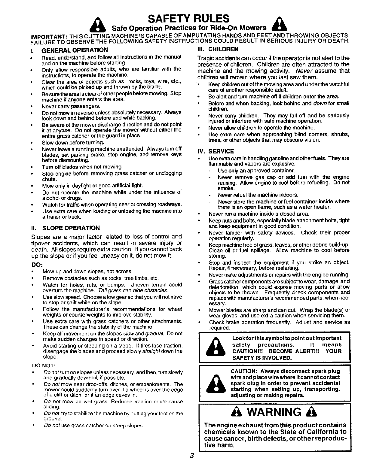
Lookfor this symbol to point out important
safety precautions. It means
CAUTION!!! BECOME ALERT!!! YOUR
SAFETY IS INVOLVED.
CAUTION: Always disconnect spark plug
wire and place wire where it cannot contact
&
spark plug in order to prevent accidental
starting when setting up, transporting,
adjusting or making repairs.
A WARNING
The engine exhaust from this product contains
chemicals known to the State of California to
cause cancer, birth defects, or other reproduc-
tive harm.
3
TABLE OF CONTENTS
SAFETY RULES ............................................................ 3
PRODUCT SPECIFICATIONS ...................................... 2
CUSTOMER RESPONSIBILITIES ..................... 2, 15-19
WARRANTY .................................................................. 2
ASSEMBLY ............................................................... 6-8
OPERATION ............................................................ 9-14
MAINTENANCE SCHEDULE ..................................... 15
INDEX
A
Adjustments:
Brake ............................................ 22
Carburetor .................................... 25
Mower
Front-To-Back ......................... 21
Side-To-Side ................. :......... 20
Throttle Control Cable .................. 25
Air Filter, Engine .................................. 18
Air Screen, Engine .............................. 18
Assembly ............................................ 6-8
B
Battery:
Charging ........................................ 7
Cleaning ....................................... 16
Starting with Weak Battery ........... 23
Storage ........................................ 26
Terminals ..................................... 16
Belt:
Motion Drive
Removal/Replacement ............ 22
Mower Belt(s)
Removal/Replacement ............ 21
Blade:
Sharpening ................................... 16
Replacement ................................ 16
Brake Adjustment ................................ 22
C
Carburetor Adjustment ........................ 25
Controls, Tractor ................................. 10
Customer Responsibilities .............. 15-19
Engine:
Air Filter .................................... 18
Air Screen ................................ 18
Cooling Fins ............................. 18
Engine Oil ........................... 12,17
Fuel Filter ................................. 19
Spark Plug(s) ........................... 19
Tractor:,
Battery ...................................... 16
Blade ........................................ 16
Lubrication Chart ...................... 15
Maintenance Schedule ............ 15
Tire Care .......................... 8,16,23
Transaxle ................................. 17
Cutting Height, Mower ......................... 11
E
Electrical:
interlOCks and Relays ................... 24
Schematic .................................... 29
Wiring Diagram ............................ 30
Engine:
Air Filter ........................................ 18
Air Screen .................................... 18
Cooling Fins ................................. 18
Oil Change ................................... 17
Oil Level ....................................... 12
Oil Type ................................... 12,17
Preparation .................................. 12
Repair Parts ............................ 48-53
Starting......................................... 13
Storage ........................................ 26
Filter:
Air Filter ........................................ 18
Fuel .............................................. 19
Fuel:
Type ............................................. 12
Storage ........................................ 26
Fuse .................................................... 24
Hood Removal/Installation .................. 24
Leveling Mower Deck .......................... 21
Lubrication:
Chart ............................................ 15
Engine .......................................... 17
Maintenance Schedule ....................... t5
Mower:
Adjustment, Front-to-Back ........... 21
Adjustment, Side-to-Side ............. 20
Blade Replacement ...................... 16
Blade Sharpening ........................ 16
Cutting Height .............................. 11
Installation .................................... 20
Operation ..................................... 12
Removal ....................................... 20
Mowing Tips ........................................ 14
Muffler ................................................. 19
Spark Attester ........................... 2,40
Oil:
Cold Weather Conditions ........ 12,t 7
Engine .......................................... 17
Storage ........................................ 26
Operation ......................................... 9-14
Operating Mower ................................ 12
SERVICE AND ADJUSTMENTS ........................... 21
STORAGE .................................................................
TROUBLESHOOTING ........................................... 2;
REPAIR PARTS - TRACTOR ................................ 3(
REPAIR PARTS - ENGINE .................................... 41
PARTS ORDERING/SERVICE ............... BACK CO_
Options:
Accessories ................................
Spark Arrester ........................... :
P
Parking Brake ................................. 1_
Parts Bag ..........................................
Pads, Replacement/Repair ............ 3_
Product Specifications .......................
R
F
Repair Parts ................................... 3
S
Safety Rules ......................................
Seat ...................................................
Service and Adjustments ............... 2
Carburetor ..................................
Fuse ...........................................
H
L
M
O
Hood Removal/Installation .........
Motion Ddve Belt
Removal/Replacement ..........
Mower Belt(s)
Removal/Replacement ..........
Mower Adjustment
Frant-to-Back .......................
Side-to*Side ..........................
Mower Removal/Installation ......
Tire Care .............................. 8,1
Slope Guide Sheet ...........................
Spark Plug(s) ...................................
Specifications ...................................
Starting the Engine ........................ 1
Steering Wheel .................................
Stopping the Tractor .........................
Storage .............................................
T
Throttle Control Cable Adjustment ..
Tires ............................................ 8,
Troubleshooting Chart .................... :
Transaxle ....................................... .
W
Warranty ..........................................
Wiring Diagram ...............................
Wiring Schematic ............................
4

CONTENTS OF HARDWARE PACK
Parts Bag contents shown full size
(1) Large F_at (1) Hex Belt
Washer 3/8-16 x 1
O
_(3) Tinnerman Clips
(1) Lockwasher 3/8
@
(1) Hex Bolt 5116-18 x 1-1/4
(1) Locknut 5/16-18
Parts packed separately in carton
Seat
0
Steering
Wheel
Steering
Sleeve
Mulcher
Plate
i
(1) Shoulder
Bolt 5/16-18
(1) Hex Bolt
1/2-13 x 1
©
(1) Lock Washer 1/2
(1) Washer 17/32 x 1-3/16 x 12 Gauge
(2) Weld Nuts #10 ,_
(2) Screws _. _ I
.0x5/8/ . Li!
(2) Lock L _ )(2) Washers
_,_1_ Washers _. / 3/16 x 3/4 x
#10 _ 16 Gauge
(2) Hex Bolts _" Y_L'_ (2) Hex
1/4-20 x 3/4 _ Nuts1/4-20
' 9/32 x 5/8 (2) Lock
x 16 Gauge Washers 1/4
(2) Washers
Manu_
Parts bag contents not shown full size
_ /F_ (2)Washers 3/8
(2) Shoulder (_'_) __j x7/8x14 Gauge
Bolts \ _/.//(2) Gauge _ (2) Center-
_j= Steering
/ Wheel
Wheel
Adapter
Insert (2) Keys
Steering ::€ Assemblys
Wheels _ lock Nuts
Parts Bag
(2) Latch Hook
i
Steering
Extension
Shaft
J
i
io
Slope Sheet
5
ASSEMBLY
Your new tractor has been assembled at the factory withexception of those parts left unassembled for shipping purposes.
To ensure safe and proper operation of your tractor all partsand hardware you assemble mustbe tightened securely. Use
the correct tools as necessary to insure proper tightness.
TOOLS REQUIRED FOR ASSEMBLY
A socket wrench set willmake assembly easier. Standard
wrench sizes are listed.
(1) 3/4" Socket w/drive rachet Utility knife
(2) 7116"wrenches Tire pressure gauge
(2) 1/2=wrenches
(1) 9116"wrench
When dght or left hand is mentioned in this manual, it
means when you are in the operating position (seated
behind the steering wheel).
TO REMOVETRACTOR FROM CARTON
UNPACK CARTON
• Remove all accessible loose parts and parts cartons
from carton (See page 5).
• Cut, from top to bottom, along lines on all four comers
of carton, and lay panels flat.
• Check for any additional loose parts or cartons and
remove.
STEERING ""-.-_./,
WHEEL 1
_' i "_,""-INSERT
3/8 HEX BOLT
3/8 LOCK WASHER
@1:------_ LARGE FLAT
WASHER
,/
J
;TEERING
SLEEVE
ADAPTER
I EXTENSION SHAFT
BEFORE ROLUNG TRACTOR OFF SKID
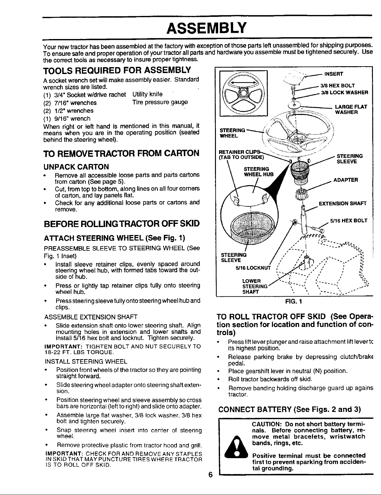
A'I-rACH STEERING WHEEL (See Fig. 1)
PREASSEMBLE SLEEVE TO STEERING WHEEL (See
Fig. 1 Inset)
Install sleeve retainer clips, evenly spaced around
steering wheel hub, with formed tabs toward the out-
side of hub.
• Press or lightly tap retainer clips fully onto steering
wheel hub.
Press stee ring sleeve fully onto steedng wheel hub and
clips.
ASSEMBLE EXTENSION SHAFT
Slide extension shaft onto lower steering shaft. Align
mounting holes in extension and lower shalts and
install5/16 hex bolt and Iocknut. Tighten securely.
IMPORTANT: TIGHTEN BOLT AND NUT SECURELY TO
18-22 FT. LBS TORQUE.
INSTALL STEERING WHEEL
Position front wheels ofthe tractor so they are pointing
straight forward.
Slide steering wheel adapter onto steering shaft exten-
sion.
Position steering wheel and sleeve assembly so cross
bars are horizontal (left to right) and slide onto adapter.
Assemble large flat washer, 3/8 lock washer, 3/8 hex
bolt and tighten securely.
Snap steering wheel insert into center of steering
wheel.
Remove protective plastic from tractor hood and grill.
IMPORTANT: CHECK FOR AND REMOVE ANY STAPLES
IN SKID THAT MAY PUNCTURE TIRES WHERE TRACTOR
IS TO ROLL OFF SKID,
5/16 HEX BOLT
FIG. 1
TO ROLL TRACTOR OFF SKID (See Opera-
tion section for location and function of con-
trols)
Press liftlever plunger and raise attachment liftlever t¢
its highest position.
• Release parking brake by depressing ciutch/brak_
pedal.
• Place gearshift lever in neutral (N) position.
• Roll tractor backwards off skid.
• Remove banding holding discharge guard up agains
tractor.
CONNECT BATTERY (See Figs. 2 and 3)
CAUTION: Do not short battery termi-
nals. Before connecting battery, re-
move metal bracelets, wristwatch
bands, rings, etc.
&
6
Positive terminal must be connected
first to prevent sparking from acciden-
tal grounding.
ASSEMBLY
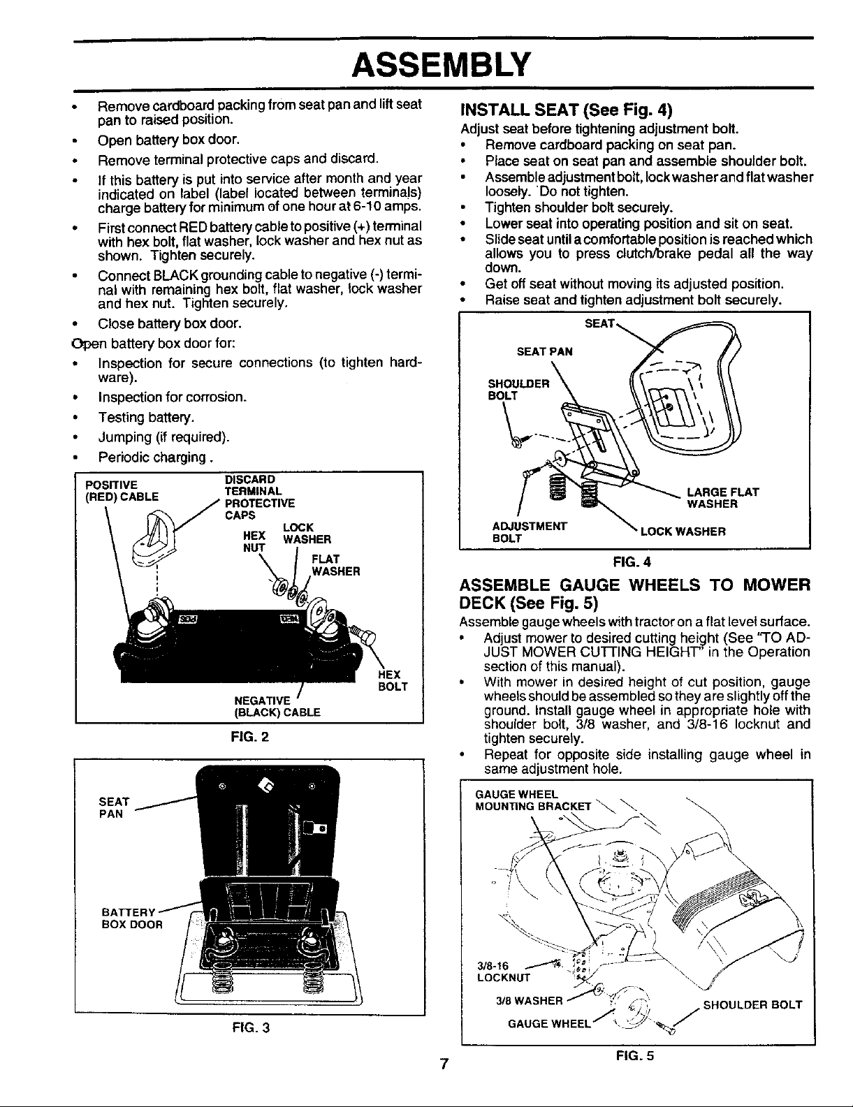
Remove cardboard packing from seat pan and lift seat
pan to raised position.
Open battery box door.
Remove terminal protective caps and discard.
If this battery is put into service after month and year
indicated on label (label located between terminals)
charge battery for minimum of one hour at 6-10 amps.
• First connect RED battery cable to positive (+)terminal
with hex bolt, flat washer, lock washer and hex nut as
shown. Tighten securely.
• Connect BLACK grounding cable to negative (-) termi-
nal with remaining hex bolt, flat washer, lock washer
and hex nut. Tighten securely.
• Close battery box door.
Open battery box door for:
• Inspection for secure connections (to tighten hard-
ware).
• Inspection for corrosion.
• Testing battery.
• Jumping (if required).
• Periodic charging.
POSITIVE
(RED) CABLE
DISCARD
TERMINAL
PROTECTIVE
CAPS
HEX WASHER
NUT
NEGATIVE
(BLACK) CABLE
LOCK
FLAT
NASHER
HEX
BOLT
FIG. 2
SEAT
PAN
INSTALL SEAT (See Fig. 4)
Adjust seat before tightening adjustment bolt.
• Remove cardboard packing on seat pan.
• Place seat on seat pan and assemble shoulder bolt.
Assemble adjustment bolt, Iockwasher and flat washer
loosely. 'Do not tighten.
Tighten shoulder bolt securely.
• Lower seat intooperating position and sit on seat.
• Slide seat untila comfortable positionis reached which
allows you to press clutch/brake pedal all the way
down.
• Get off seat without moving its adjusted position.
• Raise seat and tighten adjustment bolt securely.
SEAT PAN
SHOULDER
BOLT
LARGE FLAT
WASHER
ADJUSTMENT LOCKWASHER
BOLT
FIG. 4
ASSEMBLE GAUGE WHEELS TO MOWER
DECK (See Fig. 5)
Assemble gauge wheels with tractor on a flat level surface.
• Adjust mower to desired cutting height (See 'q-O AD-
JUST MOWER CUFFING HEIGHT" in the Operation
section of this manual).
• With mower in desired height of cut position, gauge
wheels should be assembled so they are slightly off the
ground. Install gauge wheel in appropriate hole with
shoulder bolt, 3/8 washer, and 3/8-16 Iocknut and
tighten securely.
• Repeat for opposite side installing gauge wheel in
same adjustment hole.
GAUGE WHEEL
MOUN_NGBRACKET_._.
BOX DOOR
FIG. 3
SHOULDER BOLT
7
FIG. 5
ASSEMBLY
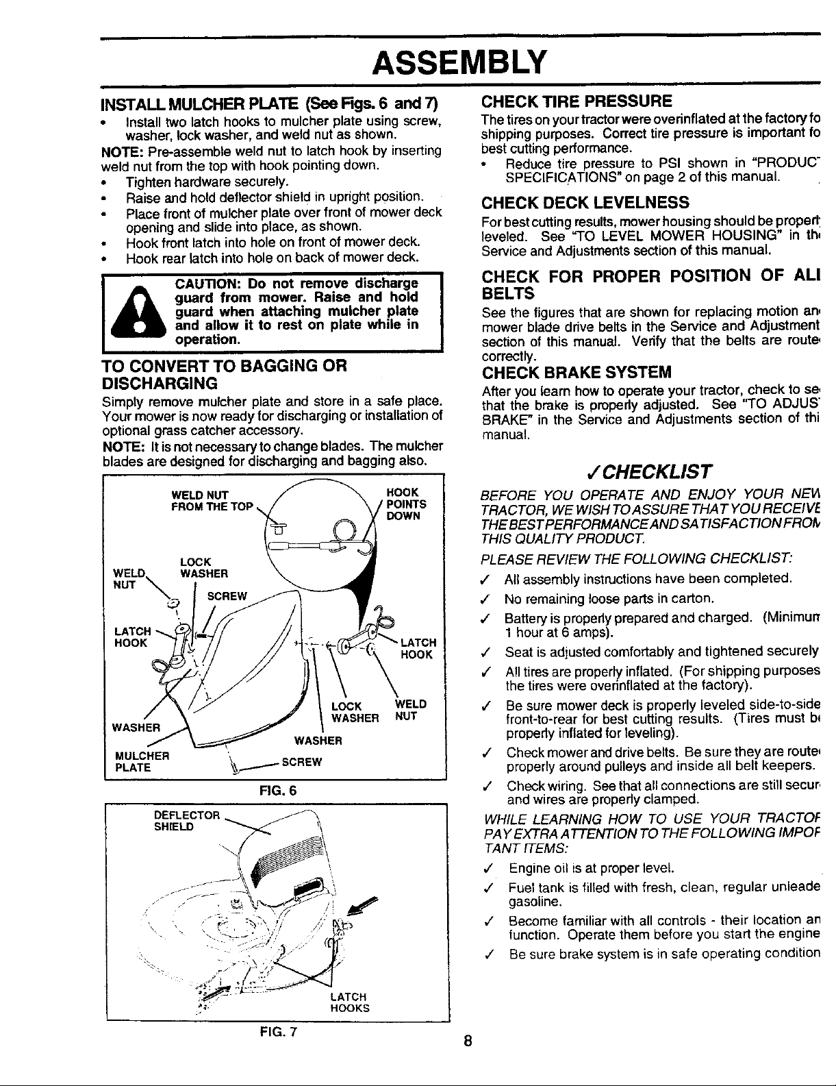
INSTALL MULCHER PLATE (See Figs. 6 and 7)
• Install two latch hooks to mulcher plate using screw,
washer, lock washer, and weld nut as shown,
NOTE: Pre-assemble weld nut to latch hook by inserting
weld nut from the top with hook pointingdown.
• Tighten hardware securely.
Raise and hold deflector shiel d inupright position.
Place front of mulcher plate over front of mower deck
opening and slide into place, as shown.
Hook rear latch into hole on back of mower deck.
CAUTION: Do not remove discharge
guard from mower. Raise and hold
i Hookront'atch'nt°ho'eonfront°fmowerdeckI
guard when attaching mulcher plate
and allow it to rest on plate while in
operation.
TO CONVERT TO BAGGING OR
DISCHARGING
Simply remove mulcher plate and store in a safe place.
Your mower is now ready for discharging or installation of
optional grass catcher accessory.
NOTE: It is not necessary to change blades. The mulcher
blades are designed for discharging and bagging also.
WELD NUT HOOK
FROM THE TOP ,_, POINTS
LOCK
WELD WASHER
NUT __ SCREW
LATCH
HOOK
LOCK WELD
WASHER NUT
WASHER
WASHER
PLATEMULCHER _SCREW
FIG. 6
DEFLECTOR _
DOWN
HOOK
s.,E,D-7<
• .. ,\ "_.__.• j _,_"
CHECK TIRE PRESSURE
The tireson yourtractorwere overinflated atthe factory fo
shippingpurposes. Correct tire pressure is important fo
best cuttingperformance.
Reduce tire pressure to PSI shown in "PRODUC"
SPECIFICATIONS" on page 2 of this manual.
CHECK DECK LEVELNESS
Forbestcuttingresults,mower housing should be propedl
leveled. See "TO LEVEL MOWER HOUSING" in th,
Service and Adjustments section of this manual.
CHECK FOR PROPER POSITION OF ALl
BELTS
See the figures that are shown for replacing motion an,
mower blade drive belts in the Service and Adjustment
section of this manual. Verify that the belts are route,
correctly.
CHECK BRAKE SYSTEM
After you learn how to operate your tractor, check to s_
that the brake is propedy adjusted. See =TO ADJUS"
BRAKE" in the Service and Adjustments section of thi
manual.
,f CHECKLIST
BEFORE YOU OPERATE AND ENJOY YOUR NEI4
TRACTOR, WE WISH TOASSURE THAT YOU RECEIVE
THE BEST PERFORMANCEAND SA TISFA C TION FROI9
THIS QUALITY PRODUCT.
PLEASE REVIEW THE FOLLOWING CHECKLIST:
1 All assembly instructions have been completed•
1 No remaining loose parts in carton.
,/ Batteryis propedyprepared and charged. (Minimur_
1 hour at 6 amps).
,/ Seat isadjusted comfortably and tightened securely
,f All tires are properly inflated• (For shipping purposes
the tireswere overinflated at the factory).
,/ Be sure mower deck is properly leveled side-to-side
front-to-rear for best cutting results. (Tires must b*
propedy inflatedfor leveling).
,/ Check mower and drive belts. Be sure they are route_
properly around pulleys and inside all belt keepers•
,/ Check wiring. Seethat all connections are still secur,
and wires are propedy clamped•
WHILE LEARNING HOW TO USE YOUR TRACTOF
PAY EXTRA ATTENTION TO THE FOLLOWING/MPOF
TANT ITEMS:
,/ Engine oil is at proper level.
,/ Fuel tank is filled with fresh, clean, regular unleade
gasoline.
v" Become familiar with all controls - their location an
lunction. Operate them before you start the engine
¢ Be sure brake system is in safe operating condition
-_:,_ - - LATCH
_;- HOOKS
FIG. 7
8
OPERATION
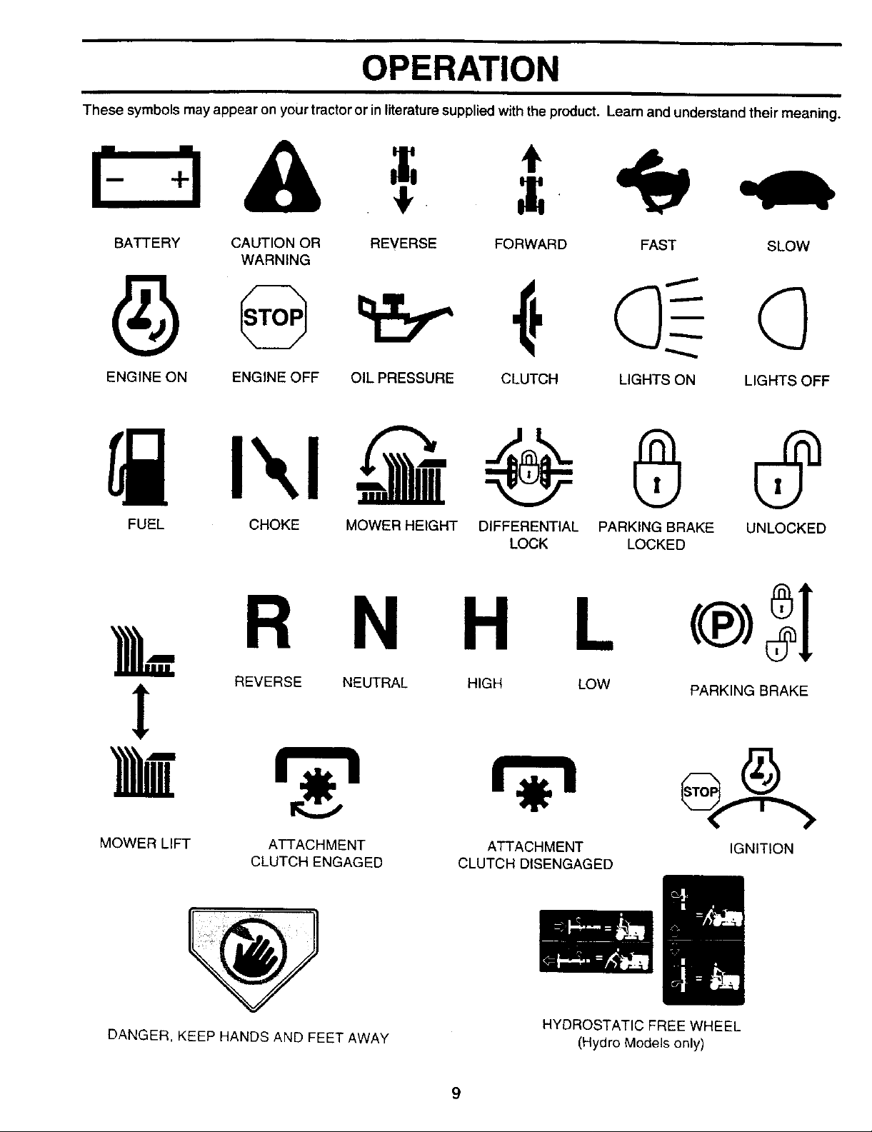
These symbols may appear on yourtractor or in literaturesupplied with the product. Learn and understand their meaning.
BATTERY CAUTION OR REVERSE FORWARD FAST SLOW
WARNING
ENGINE ON ENGINE OFF OIL PRESSURE CLUTCH LIGHTS ON LIGHTS OFF
@
FUEL CHOKE MOWER HEIGHT DIFFERENTIAL PARKING BRAKE UNLOCKED
LOCK LOCKED
k R N H L
REVERSE NEUTRAL HIGH LOW
PARKING BRAKE
!
MOWER LIFT
ATTACHMENT
CLUTCH ENGAGED
ATTACHMENT
CLUTCH DISENGAGED
IGNITION
DANGER, KEEP HANDS AND FEET AWAY
HYDROSTATIC FREE WHEEL
(Hydro Models only)
9
OPERATION
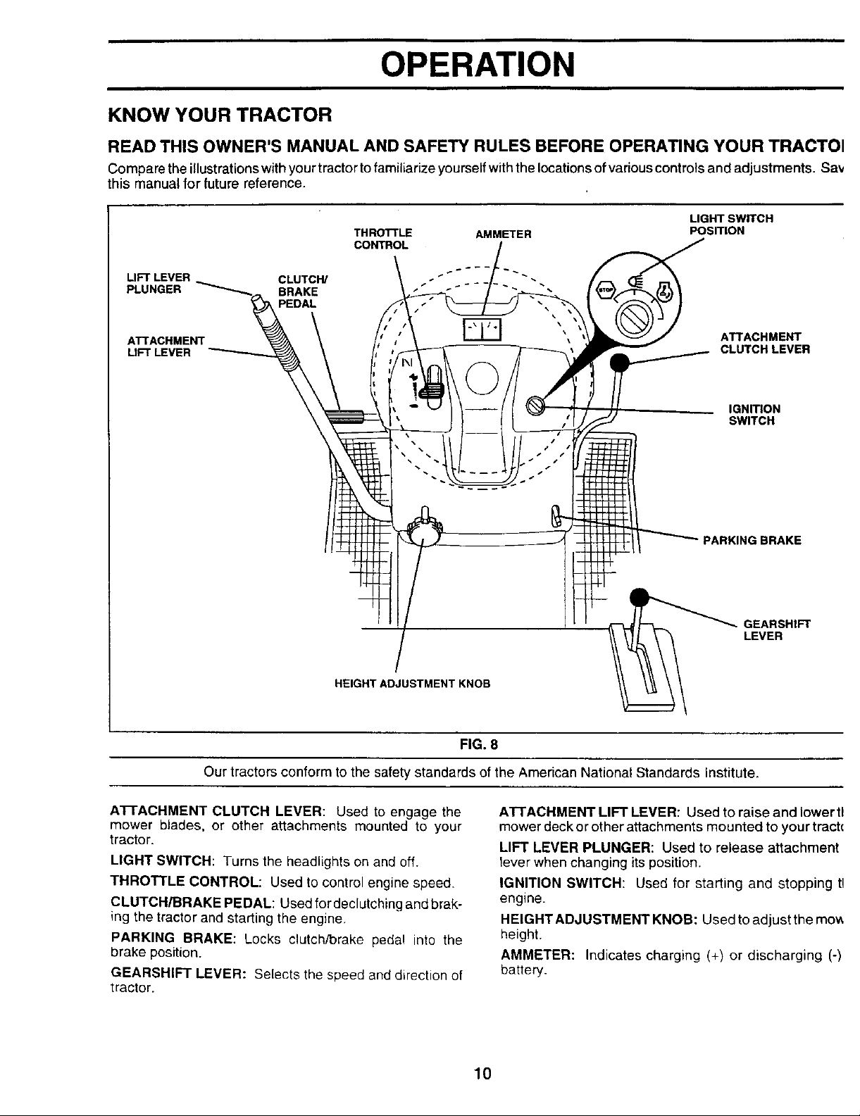
KNOW YOUR TRACTOR
READ THIS OWNER'S MANUAL AND SAFETY RULES BEFORE OPERATING YOUR TRACTOI
Compare the illustrations withyour tractor to familiarize yourself with the locations of various controls and adjustments. Say
this manual for future reference.
LIGHT SWITCH
THROTTLE AMMETER
CONTROL
LIFT LEVER CLUTCW
PLUNGER BRAKE
PEDAL
ATTACHMENT ATTACHMENT
LIFT LEVER CLUTCH LEVER
POSITION
IGNITION
SWITCH
HEIGHT ADJUSTMENT KNOB
Our tractors conform to the safety standards of the American National Standards Institute.
A'n'ACHMENT CLUTCH LEVER: Used to engage the
mower blades, or other attachments mounted to your
tractor.
LIGHT SWITCH: Turns the headlights on and off.
THROTTLE CONTROL: Used to control engine speed.
CLUTCH/BRAKE PEDAL: Used for declutching and brak-
ing the tractor and starting the engine,
PARKING BRAKE: Locks clutch/brake pedal into the
brake position.
GEARSHIFT LEVER: Selects the speed and direction of
tractor.
PARKING BRAKE
GEARSHIFT
LEVER
FIG. 8
ATTACHMENT LIFT LEVER: Used to raise and lower tl
mower deck or other attachments mounted to your trach
LIFT LEVER PLUNGER: Used to release attachment
fever when changing its position.
IGNITION SWITCH: Used for starting and stopping t!
engine,
HEIGHT ADJUSTMENT KNOB: Used to adjustthe mow
height.
AMMETER: Indicates charging (+) or discharging (-)
battery.
10
OPERATION
The operation of any tractor can result in foreign objects thrown into the eyes, which can
result in severe eye damage. Always wear safety glasses or eye shields while operating
your tractor or performing any adjustments or repairs. We recommend a wide vision
safety mask over the spectacles or standard safety glasses.
HOW TO USE YOUR TRACTOR
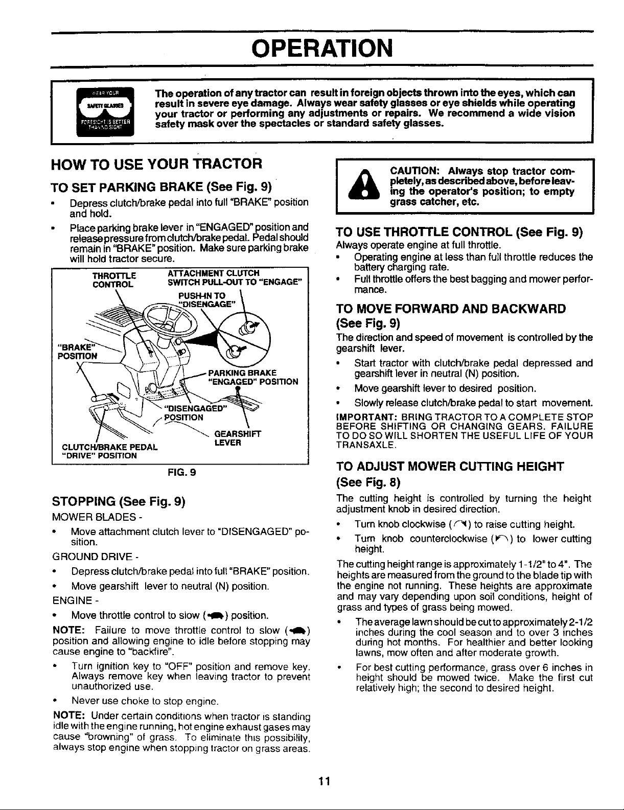
TO SET PARKING BRAKE (See Fig. 9)
Depress clutch/brake pedal into full"BRAKE" position
and hold.
Place parking brake lever in"ENGAGED" position and
release pressure from clutch/brake pedal. Pedal should
remain in"BRAKE" position. Make sure parking brake
will hold tractor secure.
THRO'R'LE ATTACHMENT CLUTCH
CONTROL SWITCH PULL-OUT TO "ENGAGE"
\ PUSH-IN TO .
"BRAKE"__
/ _ _ _ GEARSHIFT
CLUTCH/BRAKE PEDAL LEVER
"DRIVE" POSITION
FIG. 9
STOPPING (See Fig. 9)
MOWER BLADES -
• Move attachment clutch lever to "DISENGAGED" po-
sition.
GROUNODRIVE-
Depress clutch/brake pedal into full "BRAKE" position.
• Move gearshift lever to neutral (N) position.
ENGINE -
• Move throttle control to slow (.al.) position.
NOTE: Failure to move throttle control to slow (,,ab)
position and allowing engine to idle before stopping may
cause engine to "backfire".
Turn ignition key to "OFF" position and remove key.
Always remove key when leaving tractor to prevent
unauthorized use.
Never use choke to stop engine.
NOTE: Under certain conditions when tractor is standing
idle with the engine running, hot engine exhaust gases may
cause "browning" of grass. To eliminate th_s possibility,
always stop engine when stopping tractor on grass areas.
pletsly, as described above, before leav-
CAUTION: Always stop tractor com-
ing the operator's position; to empty
grass catcher, etc.
TO USE THROTTLE CONTROL (See Fig. 9)
Always operate engine at full throttle.
Operating engine at less than full throttle reduces the
battery charging rate.
• Full throttle offers the best bagging and mower perfor-
mance.
TO MOVE FORWARD AND BACKWARD
(See Fig. 9)
The directionand speed of movement is controlled bythe
gearshift lever.
Start tractor with clutch/brake pedal depressed and
gearshift lever in neutral (N) position.
• Move gearshift lever to desired position.
Slowlyrelease clutch/brake pedal to start movement.
IMPORTANT: BRING TRACTOR TO A COMPLETE STOP
BEFORE SHIFTING OR CHANGING GEARS. FAILURE
TO DO SO WILL SHORTEN THE USEFUL LIFE OF YOUR
TRANSAXLE.
TO ADJUST MOWER CU'I-I'ING HEIGHT
(See Fig. 8)
The cutting height is controlled by turning the height
adjustment knob in desired direction.
Turn knob clockwise (F_) to raise cutting height.
• Turn knob counterclockwise (P_,) to lower cutting
height.
The cutting height range is approximately 1-1/2" to 4". The
heights are measured from the ground to the blade tip with
the engine not running. These heights are approximate
and may vary depending upon soil conditions, height of
grass and types of grass being mowed.
The average lawn should becut toapproximately 2-1/2
inches during the cool season and to over 3 inches
during hot months. For healthier and better looking
lawns, mow often and after moderate growth.
For best cutting performance, grass over 6 inches in
height should be mowed twice. Make the first cut
relatively high; the second to desired height.
11
OPERATION
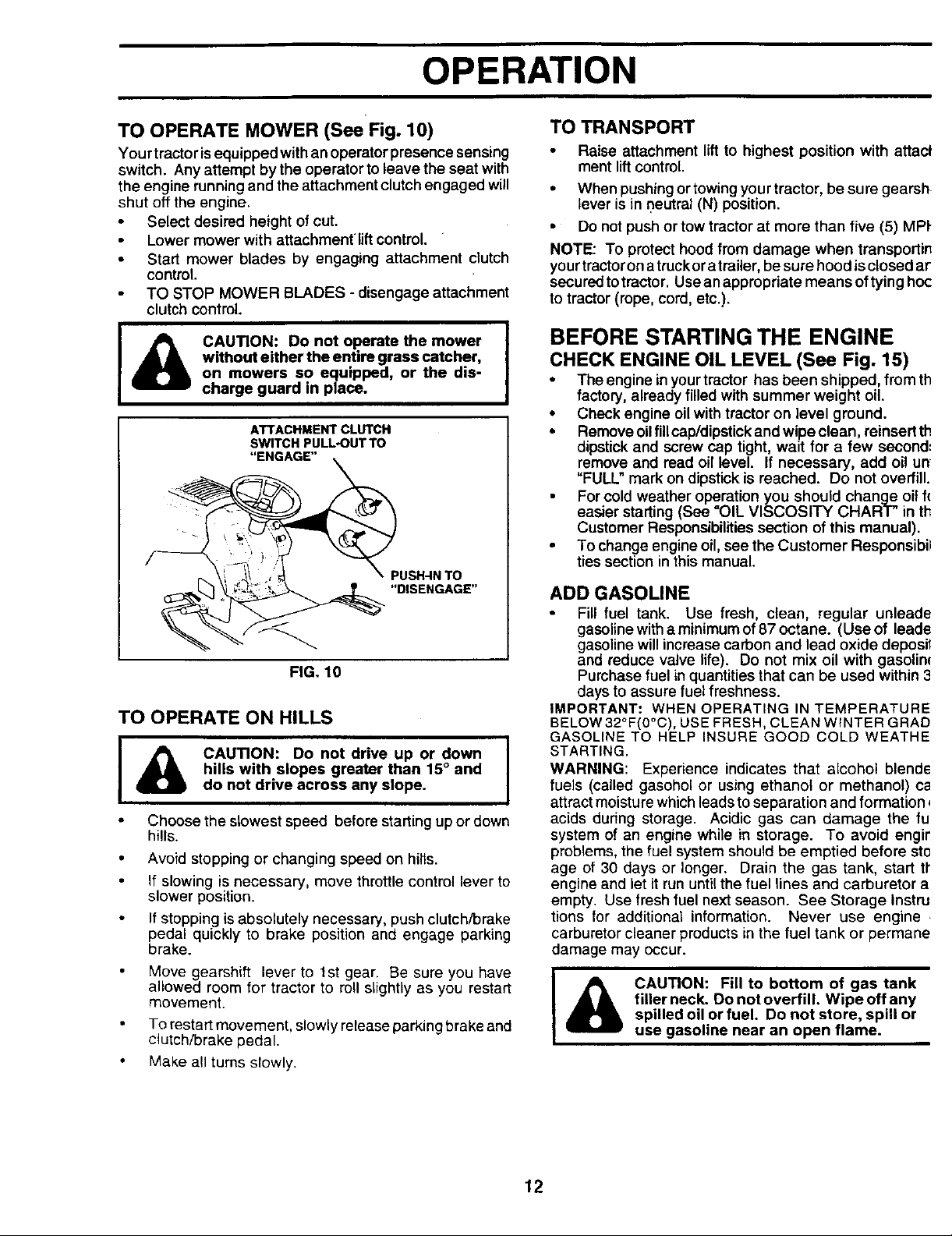
TO OPERATE MOWER (See Fig. 10)
Your tractoris equipped with an operatorpresence sensing
switch. Any attempt by the operator to leave the seat with
the engine runningand the attachment clutch engaged will
shut off the engine.
Select desired height ofcut.
Lower mower with attachment liftcontrol.
• Stad mower blades by engaging attachment clutch
control.
TO STOP MOWER BLADES - disengage attachment
clutch control.
CAUTION: Do not operate the mower
without either the entire grass catcher,
on mowers so equipped, or the dis-
charge guard in place.
ATTACHMENT CLUTCH
SWITCH PULL*OUT TO
"ENGAGE"
PUSH-IN TO
"DISENGAGE"
FIG. 10
TO OPERATE ON HILLS
hills with slopes greater than 15° and
CAUTION: Do not drive up or down |
do not drive across any slope.
Choose the slowest speed before starting up or down
hills.
Avoid stopping or changing speed on hills.
If slowing is necessary, move throttle control lever to
slower position,
If stepping is absolutely necessary, push clutch/brake
pedal quickly to brake position and engage parking
brake.
Move gearshift lever to 1st gear. Be sure you have
allowed room for tractor to roll slightly as you restart
movement.
To restart movement, slowly release parking brake and
clutch/brake pedal.
Make all tums slowly.
TO TRANSPORT
• Raise attachment lift to highest position with attacl
ment lift control.
• When pushing ortowing your tractor, be sure gearsh
lever is in neutral (N) position.
• Do not push or tow tractor at more than five (5) MPI-
NOTE: To protect hood from damage when transportir_
your tractor on a truck or a trailer, be sure hood is closed ar
securedtotractor. Useanappropriate meansof tying hoc
to tractor (rope, cord, etc.).
BEFORE STARTING THE ENGINE
CHECK ENGINE OIL LEVEL (See Fig. 15)
• Theengine in your tractor has been shipped, from th
factory, already filled withsummer weight oil.
• Check engine oilwith tractor on level ground.
• Remove oilfill cap/dipstickand wipe clean, reinsert th
dipstick and screw cap tight,wait for a few second:
remove and read oil level. If necessary, add oil un'
"FULL" mark on dipstick is reached. Do not overfill.
For cold weather operation you should change oil f(
easier starting (See "OIL VISCOSITY CHART" in th
Customer Responsibilities section of this manual).
To change engine oil, see the Customer Responsibil
ties section in this manual.
ADD GASOLINE
Fill fuel tank. Use fresh, clean, regular unleade
gasolinewitha minimum of 87 octane. (Use of leade
gasolinewill increase carbon and lead oxide deposil
and reduce valve life). Do not mix oil with gasolim
Purchase fuel in quantitiesthat can be used within 3
days to assure fuel freshness.
IMPORTANT: WHEN OPERATING IN TEMPERATURE
BELOW 32°F(0°C), USE FRESH, CLEAN WINTER GRAD
GASOLINE TO HELP INSURE GOOD COLD WEATHE
I
STARTING.
WARNING: Experience indicates that alcohol blende
fuels (called gasohol or using ethanol or methanol) ca
I
attractmoisture whichleadsto separation and formation,
acids during storage. Acidic gas can damage the fu
system of an engine while in storage. To avoid engir
problems, the fuel system should be emptied before sto
age of 30 days or longer. Drain the gas tank, start tr
engine and let it run until the fuel lines and carburetor a
empty. Use fresh fuel next season. See Storage Instra
tions for additional information. Never use engine ,
carburetor cleaner products in the fuel tank or permane
damage may occur.
filler neck. Do not overfill. Wipe off any
I & CAUTION: Fill to bottom of gas tank
spilled oil or fuel. Do not store, spill or
use gasoline near an open flame.
12
OPERATION
TO START ENGINE (See Fig. 9)
When starting the engine for the firsttime or if the engine
has run out of fuel, it will take extra cranking time to move
fuel from the tank to the engine.
Depress clutch/brake pedal and set parking brake.
• Place gear shift lever in neutral (N) position.
• Move attachment clutch to "DISENGAGED" position.
Move throttle control to choke (N) position.
Note: Before starting, read the warm and cold starting
procedures below.
Insert key intoignition and turn keyclockwise to"START'
position and release key as soon as engine starts. Do
not run starter continuously for more than fifteen sec-
onds per minute. If the engine does not start after
several attempts, move throttle control to fast (,t_)
position, wait afew minutes and try again. Ifengine still
does not start, move the throttle control back to the
choke (l"J) position and retry.
WARM WEATHER STARTING (50° F and above)
• When engine starts, move thethrottle control to the fast
(,_) position.
The attachments and ground ddve can now be used. If
the engine does not accept the load, restart the engine
and allow it to warm upfor one minute using the choke
as described above.
COLD WEATHER STARTING ( 50° F and below)
• When engine starts, allow engine to runwith the throttle
control in the choke (\1) position until the engine runs
roughly, then move thrott e contro to fast (,_) position.
This may require an engine warm-up period from
several seconds to several minutes, depending on the
temperature.
• The attachments can also be used during the engine
warm-up period.
NOTE: If at a high altitude (above 3000 feet) or in cold
temperatures (below 32 F) the carburetor fuel mixture may
need to be adjusted for best engine performance. See 'q'O
ADJUST CARBURETOR" in the Service and Adjustments
section of this manual.
MOWING TIPS
• Tire chainscannot be used when the mower housing is
attached to tractor.
• Mower should be properly leveled for best mowing
performance. See "TO LEVEL MOWER HOUSING" in
the Service and Adjustments section of this manual.
• The left hand side of mower should be used for trim-
ming.
• Drive so that clippings are discharged onto the area
that has been cut. Have the cut area to the right of the
machine. This will result in a more even distribution of
clippings and more uniform cutting.
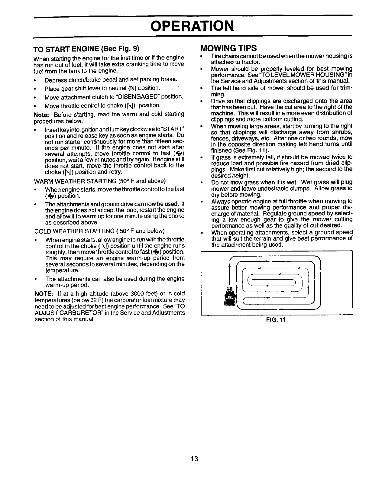
• When mowing large areas, startby turning to the dght
so that clippings will discharge away from shrubs,
fences, ddveways, etc. After one ortwo rounds, mow
in the opposite direction making left hand turns until
finished (See Fig. 11).
If grass is extremely tall, it should be mowed twice to
reduce load and possible fire hazard from dded clip-
pings. Make first cut relatively high; the second to the
desired height.
• Do not mow grass when it is wet. Wet grass will plug
mower and leave undesirable clumps. Allow grassto
dry before mowing.
Always operate engine at full throttle when mowing to
assure better mowing performance and proper dis-
charge of material. Regulate ground speed by select-
ing a low enough gear to give the mower cutting
performance as well as the quality of cut desired.
When operating attachments, select a ground speed
that will suit the terrain and give best performance of
the attachment being used.
FIG, 11
13
OPERATION
MULCHING MOWING TIPS
IMPORTANT: FOR BEST PERFORMANCE, KEEP
MOWER HOUSING FREE OF BUILT-UP GRASS AND
TRASH. CLEAN AFTER EACH USE.
The special mulching blade will recut the grass clip-
pings many times and reduce them in size so that as
they fall onto the lawn they will-disperse into the grass
and not be noticed. Also, the mulched grass will
biodegrade quickly to provide nutrients for the lawn.
Always mulch with your highest engine (blade) speed
as this will provide the best recutting action of the
blades.
• Avoid cuttingyour lawn when itiswet. Wet grass tends
to form clumpsand interfereswith the mulching action.
The best time to mow your lawn isthe eady afternoon.
At thistime the grass has ddedand the newly cut area
will not be exposed to the direct sun.
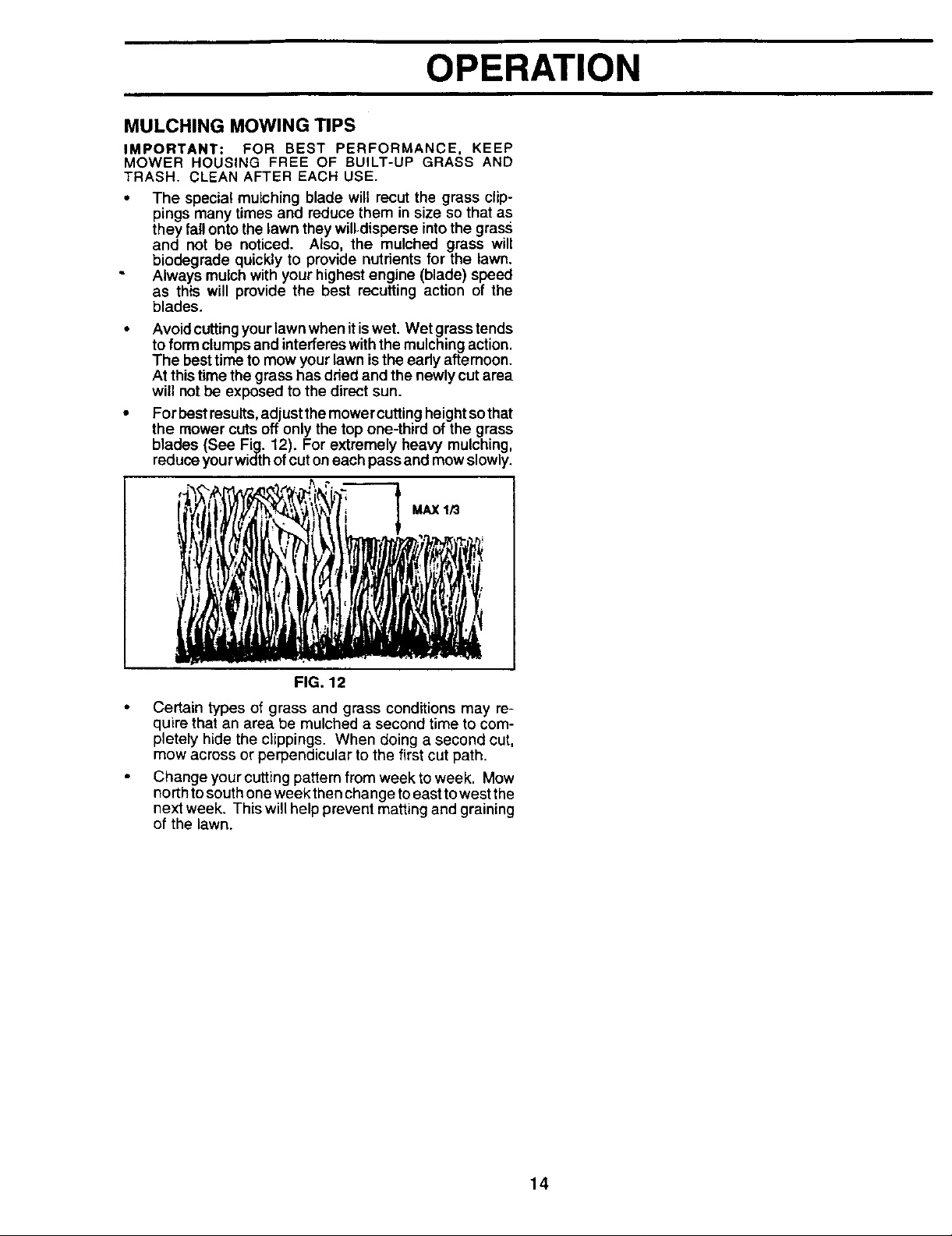
• For best results,adjust themower cuttingheightso that
the mower cuts off only the top one-third of the grass
blades (See Fig. 12). For extremely heavy mulching,
reduceyourwidth ofcuton each passand mow slowly.
MAX 1/3
FIG. 12
Certain types of grass and grass conditions may re-
quire that an area be mulched a second time to com-
pletely hide the clippings. When doing a second cut,
mow across or perpendicular to the first cut path.
Change your cutting pattern from week to week. Mow
north to south one week then change toeast to west the
next week. This will help prevent matting and graining
of the lawn.
14
CUSTOMER RESPONSIBILITIES
FILL IN DATES j_'_._ _ _..>'__-.t_'_ ,_,_; A._' ,q.'< ,q._ _
AS YOU COMPLETE _/_._0_ __ .......
REGULARSERVICE _,1_ Y _ _.."_/¢'_ _.'_.:/_,_" SERVICE DATES
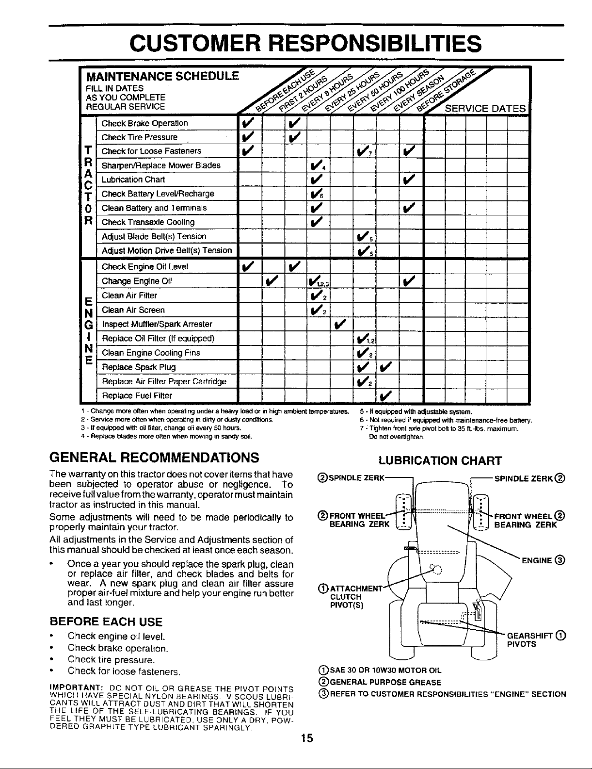
Check Brake Operation _1_ _1
Check Tire Pressure
T Check for Loose Fasteners I_ V'7 ¥4
R
Sharpen/Replace Mower Blades 11_4
LubricationChart !
T Check Battery Level/Recharge
Clean Battery and Terminals
R CheckTransaxleCooling If
AdjustBlade Belt(s) Tension VPs
AdjustMotion Drive Be_t(s)Tension Vts
Check Engine Oil Level V _ I
Change Engine Oil V' I_t_.3 I V #
Clean Air Filter V'2
E
N Clean Air Screen 1112
G InspectMuffler/Spark AtTester
I Replace Oil Filter (If equipped) Ik_1.2
N C_eanEngine Cooling Fins V'2
Replace Spark Plug II_ if
V'2Replace Air Filter Paper Cartridge
Replace Fuel Filter V'
1 - Change rn_e often when operating under a heavy load or in high ambient temperatun_.
2 - Service more often when operating in dirty or"dusty cond'_ons.
3 - If equ_ped with oilfilter, change oilevery 50 hours.
4 - Replace btades more often when mowing in sandy soil.
GENERAL RECOMMENDATIONS
The warranty on thistractor does not cover itemsthat have (_
been subjected to operator abuse or negligence. To
receive full value from the warranty, operator must maintain
tractor as instructed in this manual.
Some adjustments will need to be made periodically to (_
properly maintain your tractor. BEARINGZERK
All adjustments in the Service and Adjustments section of
this manual should be checked at least once each season.
Once a year you should replace the spark plug, clean
or replace air filter, and check blades and belts for
wear. A new spark plug and clean air filter assure
proper air-fuel mixture and help your engine run better (_) CLUTCH
and last longer. PIVOT(S)
BEFORE EACH USE
Check engine oil level.
Check brake operation.
Check tire pressure.
Check for loose fasteners.
IMPORTANT: DO NOT OIL OR GREASE THE PIVOT POINTS
WHICH HAVE SPECIAL NYLON BEARINGS. VISCOUSLUBRI-
CANTS WILL ATTRACT DUST AND DIRT THAT WILL SHORTEN
THE LIFE OF THE SELF-LUBRICATING BEARINGS. IF YOU
FEEL THEY MUST BE LUBRICATED, USE ONLY A DRY. POW-
DERED GRAPHITE TYPE LUBRICANT SPARINGLY.
(_SAE 30 OR 10W30 MOTOR OIL
(_)GENERAL PURPOSE GREASE
(_REFER TO CUSTOMER RESPONSIBILITIES "ENGINE" SECTION
15
5 - If equipped with adjustable system.
6 - Not required if equipped with maintenance-free battery.
7 :Tighten front axle pivot boltto 35 ft.-Ibs, maximum.
Do not overdghten.
LUBRICATION CHART
• FRONT WHEEL (_
BEARING ZERK
PIVOTS
(D

CUSTOMER RESPONSIBILITIES
TRACTOR TO SHARPEN BLADE (See Fig. 14)
Always observe safety rules when performing any mainte-
nance.
BRAKE OPERATION
If tractor requires more than six (6) feet stopping distance
at high speed in highest gear, then brake must be adjusted.
(See "TO ADJUST BRAKE" in the Service and Adjust-
ments section of this manua0.
TIRES
• Maintain proper air pressure in all tires (See =PROD-
UCT SPECIFICATIONS" on page 2 ofthis manual).
• Keep tires free of gasoline, oil,or insect control chemi-
cals which can harm rubber.
• Avoid stumps, stones, deep ruts, sharp objects and
other hazards that may cause tire damage.
Care should be taken to keep the blade balanced. /_
unbalanced blade will cause excessive vibration and evel
tual damage to mower and engine.
• The blade can be sharpened with a file or on a grindir
wheel. Do not attempt tosharpen while on the mowe
To check blade balance, you will need a 5/8" diamet_
steel bolt, pin, or a cone balancer. (When using a cot
balancer, follow the instructions supplied with b_
ancer).
• Slide blade on to an unthreaded portion ofthe steel Ix
or pin and hold the bolt or pin parallel with the groun,
If blade is balanced, it should remain in a horizont
position. If either end of the blade moves downwar
sharpen the heavy end until the blade is balanced.
NOTE: Do not use a nail for balancing blade. The lobes
the center hole may appear to be centered, but are not.
BLADE CARE
For best results mower blades must be kept sharp. Re-
place bent or damaged blades.
BLADE REMOVAL (See Fig. 13)
Raise mower to highest position to allow access to
blades.
Remove hex bolt, !ock washer and flat washer securing
blade.
• Installnew or resharpened blade with trailing edge up
towards deck as shown.
• Reassemble hex bolt, lock washer and flat washer in
exact order as shown.
Tighten bolt securely (30-35 Ft. Lbs. torque).
IMPORTANT: BLADE BOLT IS GRADE 8 HEATTREATED.
NOTE: We do not recommend sharpening blade - but ifyou
do, be sure the blade is balanced.
BLADE MANDREL
TRAILING EDGE
HEX BOLT
(GRADE 8)* _
*A GRADE 8 HEAT TREATED BOLT CAN BE
IDENTIFIED BY SIX LINES ON THE BOLT HEAD.
FIG. 13
CENTER HOLE
5/8" BOLT
OR PIN
FIG. 14
BLADE
BATTERY
Your tractorhas a battery charging system which issuf
cient for normal use. However, periodic charging of tl"
battery with an automotive charger will extend its life.
• Keep battery and terminals clean.
Keep battery bolts tight.
• Keep small vent holes open.
Recharge at 6-10 amperes for 1 hour.
TO CLEAN BATTERY AND TERMINALS
Corrosion and dirt on the battery and terminals can cau:
the battery to "leak" power.
Open battery box door.
Disconnect BLACK battery cable first then RE
battery cable and remove battery from tractor.
Rinse the battery with plain water and dry.
Clean terminals and battery cable ends with w
brush until bright.
• Coat terminals with grease or petroleum jelly.
Reinstall battery (See "CONNECT BATTERY" in t
Assembly section of this manual).
16
 Loading...