

Craftsman 917259572 Owner’s Manual

®
MODEL NUMBER 917.259572
e Assembly
®Operation
Customer Responsibilities
eService and Adjustments
®Repair Parts
OWNER'S MANUAL
For answers to your questions
about this product, Call:
1-800-659-5917
Sears Craftsman Help Line
5 am - 5 pm, Mort - Sat
CAUTION: Read and follow all safety rules and instructions before operating this equipment.
FOR CONSUMER ASSISTANCE HOT LINE, CALL THIS TOLL FREE NUMBER: 1-800-659-5917
IIIIIIIIIIIIIIIIIIIIIIIIIIIIIIIIIIIIIIIIIIII IIIIIIIIIIIIIIIIIIIIIIII
II I

SAFETY RULES
Safe Operation Practices for Ride-On Mowers &
IMPORTANT: THIS CUTTING MACHINE IS CAPABLE OF AMPUTATING HANDS AND FEET AND THROWING OBJECTS.
FAILURE TO OBSERVE THE FOLLOWING SAFETY INSTRUCTIONS COULD RESULT IN SERIOUS INJURY OR DEATH.
I. GENERAL OPERATION
• Read, understand, and foIiow ali instructions in the manual
and on the machine before starting.
= Only aflow responsible adults, who are familiar with the
instructions, to operate the machine
• Clear the area of objects such as rocks, toys, wire, etc,
which could be picked up and thrown by the blade
• Be sure the area isclear of other people before mowing. Stop
machine if anyone enters the area
- Never carry passengers
, Do not mow in reverse unless absolutely necessary Aiways
look down and behind before and while backing.
, Be aware of the mower discharge direction and do not point
it at anyone Do not operate the mower without either the
entire grass catcher or the guard in place
, Slow down before turning
° Never leave a running machine unattended. Always turn off
blades, set parking brake, stop engine, and remove keys
before dismounting.
° Turn off blades when not mowing,
° Stop engine before removing grass catcher or unc]ogging
chute.
• Mow only in daylight or good artificial light,
- Do not operate the machine while under the influence of
alcohol or drugs.
° Watch for traffic when operating near or crossing roadways,
• Use extra care when loading or unloading the machine into
a trailer or truck,
I1. SLOPE OPERATION
Slopes are a major factor related to loss_of-control and
tipover accidents, which can result in severe injury or
death, All slopes require extra caution, If you cannot back
up the slope or if you feel uneasy on it, do not mow iL
DO:
,, Mow up and down slopes, not across.
= Remove obstacles such as rocks, tree limbs, etc..
• Watch for holes, ruts, or bumps. Uneven terrain coutd
overturn the machine Tall grass can hide obstacles.
° Use slow speed._ Choose alow gear so that you wil! not have
to stop or shift while on the slope,.
• Follow tire manufacturer's recommendations for wheel
weights or counterweights to improve stability.
• Use extra care with grass catchers or other attachments.
These can change the stability of the machine.
° Keep all movement on the slopes slow and gradual, Do not
make sudden changes in speed or direction,
° Avoid starting or stopping on a slope. If tires lose traction,
disengage the blades and proceed slowly straight down the
slope.
DO NOT;
= Do not turn on slopes unless necessary, and then, turn slowly
and gradually downhill, if possible_
° Do not mow near drop-otis, ditches, or embankments. The
mower could suddenty turn over if a wheel is over the edge
of a cliff or ditch, or if an edge caves in.
• Do not mow on wet grass. Reduced traction could cause
sliding.
• Donottrytostabilizethemachinebyputtingyourfootonthe
g_ound,
• Do not use grass catcher on steep slopes.
III. CHILDREN
Tragic accidents can occur if the operator is not alert to the
presence of children. Children are often attracted to the
machine and the mowing activity_ Never assume that
children will remain where you last saw them.
= Keep children out of the mowing area and under the watchful
care of another responsible adult.
• Be aled and turn machine off if children enter the area
° Before and when backing, took behind and down for small
children
= Never carry children They may fall off and be seriously
injured or interfere with safe machine operation.
• Never allow children to operate the machine.
• Use extra care when approaching blind corners, shrubs,
trees, or other objects that may obscure vision_
IV. SERVICE
• Use extra care inhandling gasoline and other fuels. They are
flammable and vapors are explosiv&
Use only an approved container
Never remove gas cap or add fuel with the engine
running. Allow engine to cool before refueling.. Do not
smoke.
Never refuel the machine indoors.
Never store the machine or fuel container inside where
• Never run a machine inside a closed area..
° Keep nuts and bolts, especially blade attachment bolts, tight
° Never tamper with safely devices.. Check their proper
• Keep machine free ofgrass, leaves, or other debds build-upo
o Stop and inspect the equipment if you strike an object,
• Never make adjustments or repairs with the engine running,
• Grass catcher components are subject to wear, damage, and
o
°
!
there is an open flame, such as a water heater.
and keep equipment in good condition.
operation regularly°
Clean oil or fuel spillage, Allow machine to cool before
storing
Repair, if necessary, before restarting.
deterioration, which could expose moving parts or aIIow
objects to be thrown. Frequently check components and
replace with manufacturer's recommended parts, when nec-
essary,
Mower blades are sharp and can cut Wrap the blade(s) or'
wear gloves, and use extra caution when servicing them.
Check brake operation frequently. Adjust and service as
require&
Look for this symbo! to point out important
safety precautions. It means
CAUTIONI!t BECOME ALERTIII YOUR
SAFETY IS INVOLVED.
i ...... iiiiiii1,,,
CAUTION: Always disconnect spark plug
spark plug in order to prevent accidental
wire and place wire where it cannot contact
starting when setting up, transporting,
adjusting or making repairs_
WARNING &
Theengineexhaust fromthis product contains
chemicals known to the State of California to
cause cancer, birth defects, or other reproduc-
tive harm.

CONGRATULATIONS on your purchase of a Sears
Tractor. It has been designed, engineered and manufac-
tured to give you the best possible dependability and
performance°
Should you experience any problem you cannot easily
remedy, please contact your nearest Sears Authorized
Service Center/Department Department_ We have com-
petent, well-trained technicians and the proper tools to
service or repair this tractor.
Please read and retain this manual. The instructions will
enable you to assemble and maintain your tractor properly.
Always observe the "SAFETY RULES".
MODEL
NUMBER 917.259572
SERIAL
NUMBER
DATEOFPURCHASE
THE MODELAND SERIAL NUMBERS WILL BE FOUND
ON A PLATE UNDER THE SEAT°
YOU SHOULD RECORD BOTH SERIAL NUMBER AND
DATE OF PURCHASE AND KEEP IN A SAFE PLACE
FOR FUTURE REFERENCE.
MAINTENANCE AGREEMENT
A Sears Maintenance Agreement is available on this prod-
ucL Contact your nearest Sears store for details.
PRODUCT SPECIRCATIONS
HORSEPOWER: 19..5
GASOLINE CAPACITY 3.5 GALLONS
AND TYPE: UNLEADED REGULAR
OIL TYPE (AP]-SF/SG/SH): SAE 30 (above 32°F)
SAE 5W-30 (below 32°F)
OIL CAPACITY: 3.0 PINTS
SPARK PLUG:
(GAP: °030")
VALVE CLEARANCE:
GROUND SPEED (MPH): FORWARD: 0 - 55
TIRE PRESSURE: FRONT: 14 PSI
CHARGING SYSTEM: 3 AMPS BATTERY
BATTERY: AMP/HR: 30
BLADE BOLT TORQUE: 30-35 FT. LBS.
CHAMPION RJ19LM
INTAKE: 004"- 006"
EXHAUST: .007" -..009"
REVERSE: 0-2.4
REAR: 10 PSi
5 AMPS HEADLIGHTS
MIN CCA: 240
CASE SIZE: U1R
CUSTOMER RESPONSIBILITIES
° Read and observe the safety rules.
° Follow a regutar schedule in maintaining, caring for and
using your tractor.
= Follow the instructions under"Customer Responsibili-
ties" and "Storage" sections of this owner's manual
WARNING: This tractor is equipped with an internal
combustion engine and should not be used on or near any
unimproved forest-covered, brush-covered or grass-coy-
ered land unless the engine's exhaust system is equipped
with a spark arrester meeting applicable local or state laws
(if any). If a spark arrester is used, it should be maintained
in effective working order by the operator°
In the state of California the above is required by law
(Section 4442 of the California Public ResOurces Code).
Other states may have similar laws. Federal laws apply on
federal lands. A spark arrester for the muffler is available
through your nearest Sears Authorized Service Center/
Department (See REPAIR PARTS section of this manual).
LiMiTED TWO YEAR WARRANTY ON CRAFTSMAN RIDING EQUIPMENT
For two (2) years from the date of purchase, if this Craftsman Riding Equipment is maintained, lubricated and tuned up according
to the instructions in the owner's manual, Sears will repair or replace, free of charge, any parts found to be defective in material or
workmanship.
This Warranty does not cover:
,, Expendable items which become worn during normal use, such as blades, spark plugs, air cleaners, belts, etc
• Tire replacement or repair caused by punctures from outside objects, such as nails, thorns, stumps, or glass.
• Repairs necessary because of operator abuse, negligence, imp(oper storage or accident or the failure to maintain the
equipment according to the instructionscontained in the owner's manual.
o Riding equipment used for commercial or rental purposes.
LIMITED 90 DAY WARRANTY ON BATTERY
For ninety (90) days from date of purchase, if any battery included with this riding equipment proves defective in material or
workmanship and our testing determines the battery will not hold a charge, Sears will replace the battery at no charge.
IN-HOME WARRANTY SERVICE ON YOUR CRAFTSMAN RIDING EQUIPMENT IS AVAILABLE AT NO-CHARGE FOR 30
DAYS FROM THE DATE OF PURCHASE. PLEASE CONTACT YOUR NEAREST SERVICE CENTER. AFTER 30 DAYS FROM
THE DATE OF PURCHASE, WARRANTY SERVICE IS AVAILABLE BY TAKING YOUR CRAFTSMAN RIDING EQUIPMENT TO
YOUR NEAREST SEARS SERVICE CENTER. (IN-HOME WARRANTY SERVICE WILL STILL BE AVAILABLE AFTER 30 DAYS
FROM THE DATE OF PURCHASE BUT A STANDARD TRIP CHARGE WILL APPLY) THIS WARRANTY APPLIES ONLY
WHILE THIS PRODUCT IS IN THE UNITED STATES
This Warranty gives you specific legal rights, and you may also have other rights which may vary from state to state
SEARS, ROEBUCK AND CO., D/817 WA, HOFFMAN ESTATES, IL 60179
,m..... i,,i,i i , ....................
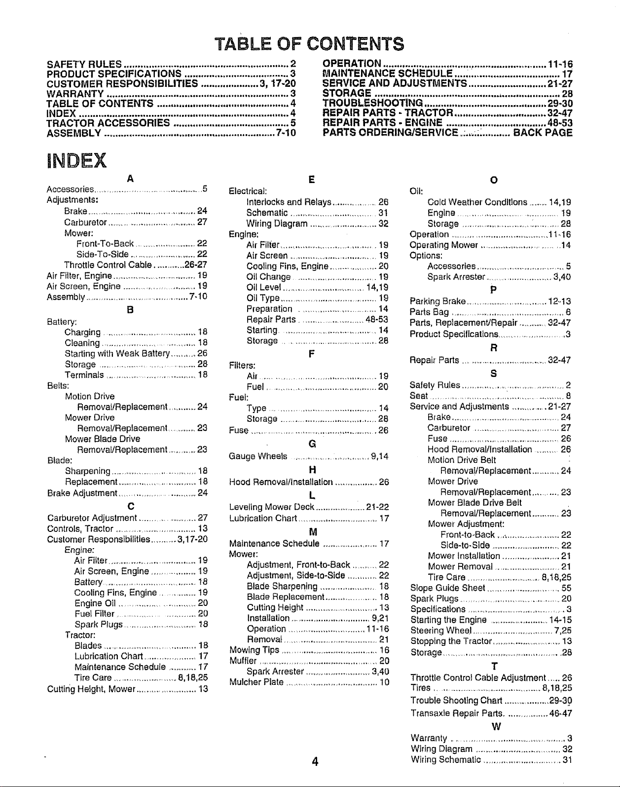
TABLE OF CONTENTS
SAFETY RULES ............................................................ 2
PRODUCT SPECIFICATIONS ...................................... 3
CUSTOMER RESPONSIBILITIES ..................... 3, 17-20
WARRANTY .................................................................. 3
TABLE OF CONTENTS ................................................ 4
INDEX ............................................................................ 4
TRACTOR ACCESSORIES .......................................... 5
ASSEMBLY .............................................................. 7-10
INDEX
A
Accessories ............................................... 5
Adjustments:
Brake ............................................. 24
Carburetor ................................... 27
Mower:
Front*To-Back ..........................22
Side-To-Side ........................... 22
Throttle Control Cable ............ 26-27
Air Filter, Engine ....................................19
Air Screen, Engine ............................ 19
Assembly ............................................ 7-10
B
Battery:
Charging ............................................18
Cleaning ........................................18
Starting with Weak Battery ........... 26
Storage ................................... 28
Terminals ........................................18
BeLts:
Motion Drive
Removal/Replacement ........... 24
Mower Drive
Removal/Replacement ..........23
Mower Blade Drive
Removal/Replacement .............23
Biade:
Sharpening ................................ 18
Replacement ................................. 18
Brake Adjustment .................................24
C
Carburetor Adjustment ....................... 27
Controls, Tractor ................................ 13
Customer Responsibilities .......... 3,17-20
Engine:
Air Fitter .................................... 19
Air Screen, Engine .................. 19
Battery...........................................18
Cooling Fins, Engine .............. 19
Engine Oil .............................. 20
Fuel Filter ................................ 20
Spark Plugs ............................... 18
Tractor:
Blades ......................................... 18
Lubrication Chart ...................... 17
Maintenance Schedule ........... 17
Tire Care .......................... 8,t8,25
Cuttir_g Height, Mower ......................... 13
Electrical:
interlocks and Relays ....................28
Schematic .................................. 31
WiringDiagram ...........................32
Engine:
Air Filter ....................................... 19
Air Screen ................................... 19
Cooling Fins, Engine ................... 20
OilChange ...................................I9
Oil Level .................................14,19
OilType ........................................19
Preparation .............................. 14
Repair Parts ............................ 48-53
Starting .....................................14
Storage.....................................28
Filters:
Air..............................................19
Fuel ............................................. 20
Fuel:
Type .......................................... 14
Storage......................................28
Fuse ..................................................26
Gauge Wheels ............................. 9,14
Hood Removatllnstallation ................. 26
Leveling Mower Deck .................... 21-22
Lubrication Chart .................................t7
Maintenance Schedule .......................17
Mower:
Adjustment, Front-to-Back .......... 22
Adjustment, Side-to-Side ............. 22
Blade Sharpening ....................... 18
Blade Replacement ..................... 18
Cutting Height ........................... 13
Installation ................................ 9,21
Operation ..............................11-16
Removal ...................................... 21
Mowing Tips ....................................... 16
Muffler ................................................ 20
Spark Attester .......................... 3,40
Mulcher Plate ..................................... 10
OPERATION ........................................................... t1-16
MAINTENANCE SCHEDULE ...... ............................... 17
SERVICE AND ADJUSTMENTS ............................ 21-27
STORAGE ............................................. ,..................... 28
TROUBLESHOOTING ............................................ 29-30
REPAIR PARTS - TRACTOR ................................. 32.47
REPAIR PARTS - ENGINE .................................... 48-53
PARTS ORDERING/SERVICE °:.,-,;;_.......... BACK PAGE
E
Oil:
Cold Weather Conditions ....... 14,19
Engine .......................................... 19
Storage .............................. i.......... 28
Operation ...................................... 11,16
Operating Mower, ............................. 14
Options:
Accessories ....................................... 5
Spark Arrestor .........................3,40
O
P
Parking Brake .................................. 12o13
Paris Bag ................................................ 6
Parts, Replacement/Repair, ...........32-47
Product Specifications ................................3
F
Repair Parts ................................. 32-47
Safety Rules .............................................. 2
Seat .......................................................... 8
Service and Adjustments ............... 21-27
Brake ............................................. 24
Carburetor ...................................... 27
G
N
L
M
Fuse .............................................. 26
Hood Removal/Installation ......... 26
Motion Drive Belt
Remova!tReplacement ............ 24
Mower Drive
Removal/Replacement ........... 23
Mower Blade Drive Belt
Removal/Repfacement ...........23
Mower Adjustment:
Front-to-Back ,,_..................... 22
Side-to-Side ............................. 22
Mower Installation ....................... 21
Mower Removal ..........................2!
Tire Care ................................ 8,18,25
Slope Guide Sheet ...............................55
Spark Plugs ........................................ 20
Specifications ........................................ 3
Starting the Engine ....................... 14-15
Steering Wheel .................................. 7,25
Stopping the Tractor ........................... 13
Storage ............................................ 28
R
S
T
Throttle Control Cable Adjustment ..... 26
Tires ............................................. 8,18,25
Trouble Shooting Chart ................... 29-3.0
Transaxle Repair Parts ................. 46-47
W
Warranty ................................................ 3
Wiring Diagram .................................. 32
Wiring Schematic ................................ 31
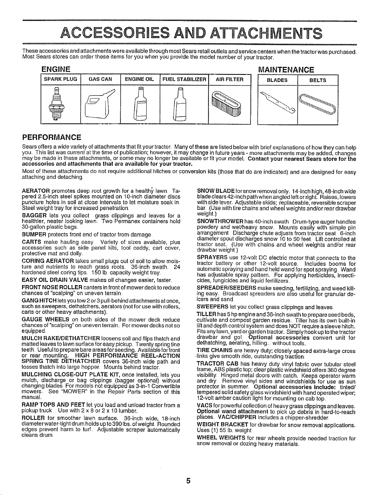
ACCESSORIES AN ATTACHMENTS
11, ,11,, ,i,,i,,,,11,, ,i i .,,,,,,
Thes eaccesso des and attachments were available through most Sears retail outlets and service centers when the tractor was purchased.
Most Sears stores can order these items for you when you provide the model number of your tractor,,
ENGINE
SPARK PLUG GAS CAN
ENGINEOILAFUEL STABILIZER
2,
AIR FILTER
%
MAINTENANCE
BLADES BELTS
PERFORMANCE
Sears offers a wide variety of attachments that fit your tractor, Many of these are listed below with brief explanations of how they can help
you, This list was current at the time of publication; however, it may change in future years - more attachments may be added, changes
may be made in these attachments, or some may no longer be available or fit your model Contact your nearest Sears store for the
accessories and attachments that are available for your tractor.
Most of these attachments do not require additional hitches or conversion kits (those that do are indicated) and are designed for easy
attaching and detaching,
AERATOR promotes deep root growth for a healthy fawn Ta-
pered 2o5-inch steel spikes mounted on 10-inch diameter discs
puncture holes in soil at close intervals to let moisture soak in,
Steel weight tray for increased penetration
BAGGER lets you collect grass clippings and leaves for a
healthier, nearer looking lawn, Two Permanex containers hold
30-gallon plastic bags.,
BUMPER protects front end of tractor from damage
CARTS make hauling easy Variety of sizes available, plus
accessories such as side panel kits, tool caddy, cart cover,
protective mat and dolly,,
CORING AERATOR takes sma{I piugs out of soil to allow mois-
ture and nutrients to reach grass roots., 36-inch swath,. 24
hardened steel coring tips, 150 lb capacity weight tray,
EASY OIL DRAIN VALVE makes oil changes easier, faster.
FRONT NOSE ROLLER canters infront of mower deck to reduce
chances of "scalping" on uneven terrain
GANG HITCH lets you tow 2 or3 pul!-behind attachments atonce,
such as sweepers, dethatchers, aerators (not for use with rollers,
carts or other heavy attachments).
GAUGE WHEELS on both sides of the mower deck reduce
chances of "scalping" onuneven terrain., For mower decks not so
equipped.
MULCH RAKFJDETHATCHER loosens soil and flips thatch and
matted leaves to lawn surface for easy pickup., Twenty spring tine
teeth Useful to prepare bare areas for seeding. Availab{e for front
or rear mounting. HIGH PERFORMANCE REEL-ACTION
SPRING TINE DETHATCHER covers 36-inch wide path and
tosses thatch into large hopper. Mounts behind tractor,
MULCHING CLOSE-OUT PLATE KIT, once installed, lets you
mulch, discharge or bag clippings (bagger optional) without
changing btades,_ For models not equipped as 3-in-1 Convertible
mowers, See MOWER in the Repair Parts section of this
manual.
RAMP TOPS AND FEET let you load and unload tractor from a
pickup truck Use with 2 x 8 or 2 x 10 lumber..
ROLLER for smoother lawn surface. 36*inch wide, 18-inch
diameter water-tight drum holds up to 390 Ibs, of weight, Rounded
edges prevent harm to turf, Adjustable scraper automatically
cleans drum
SNOW BLADE for snow removal only, 14-inch high, 48-inch wide
blade clears 42-inch path when angled left or right,, Raises lowers
with side lever,, Adiustabie skids; replaceable, reversible scraper
bar. (Use with tirechains and wheel weights and/or rear drawbar
weighL)
SNOWTHROWER has 40-inch swath Drum-type a.uger handles
powdery and wet/heavy snow. Mounts easily with simple pin
arrangement Discharge chute adjusts from tractor seat 6-inch
diameter spout discharges snow 10 to 50 feet Lift controlled at
tractor seat. (Use with chains and wheel weights and/or rear
drawbar weight )
SPRAYERS use 12-volt DC electric motor that connects to the
tractor battery or other 12-volt source,, lncfudes booms for
automatic spraying and hand held wand for spot spraying Wand
has adjustable spray pattern.r For applying herbicides, insecti-
cides, fung{cides and liquid fertilizers,
SPREADER/SEEDERS make seeding fertilizing, and weed kill-
ng easy,, Broadcast spreaders are also useful for granular de-
icers and sand
SWEEPERS let you collect grass clippings and leaves.
TILLER has 5 hp engine and 36-inch swath to prepare seed beds
cultivate and compost garden residue. Tiller has itsown built-in
tiltand depth control system and does NOT require a sleeve hitch,,
Fits any lawn, yard or garden tractor., Simply hook up to the tractor
drawbar and go! Optional accessories convert unit for
dethatching, aerating, hilling, without tools,,
TIRE CHAINS are heavy duty; closely spaced extra-large cross
.links give smooth ride, outstanding traction.
TRACTOR CAB has heavy duty vinyl fabric ever tubular stee!
frame, ABS plastic top; clear plastic windshield offers 360 degree
visibility. Hinged metal doors with catch. Keeps operator warm
and dry Remove vinyl sides and windshields for use as sun
protector in summer. Optional accessories include: tinted/
tempered solid safety glass windshield with hand operated wiper
12-volt amber caution light for mounting on cab top
VAC S for powedul collectio n of heavy grass clippings and leaves..
Optional wand attachment to pick up debris in hard-to-reach
places, VAClCHIPPER includes a chipper-shredder,
WEIGHT BRACKET for drawbar for snow removal applications,
Uses (1) 55 lb,.weight
WHEEL WEIGHTS for rear wheels provide needed traction for
snow removal or dozing heavy materials_
._...; ............................... n n' i'"1 ................................................ iii , '
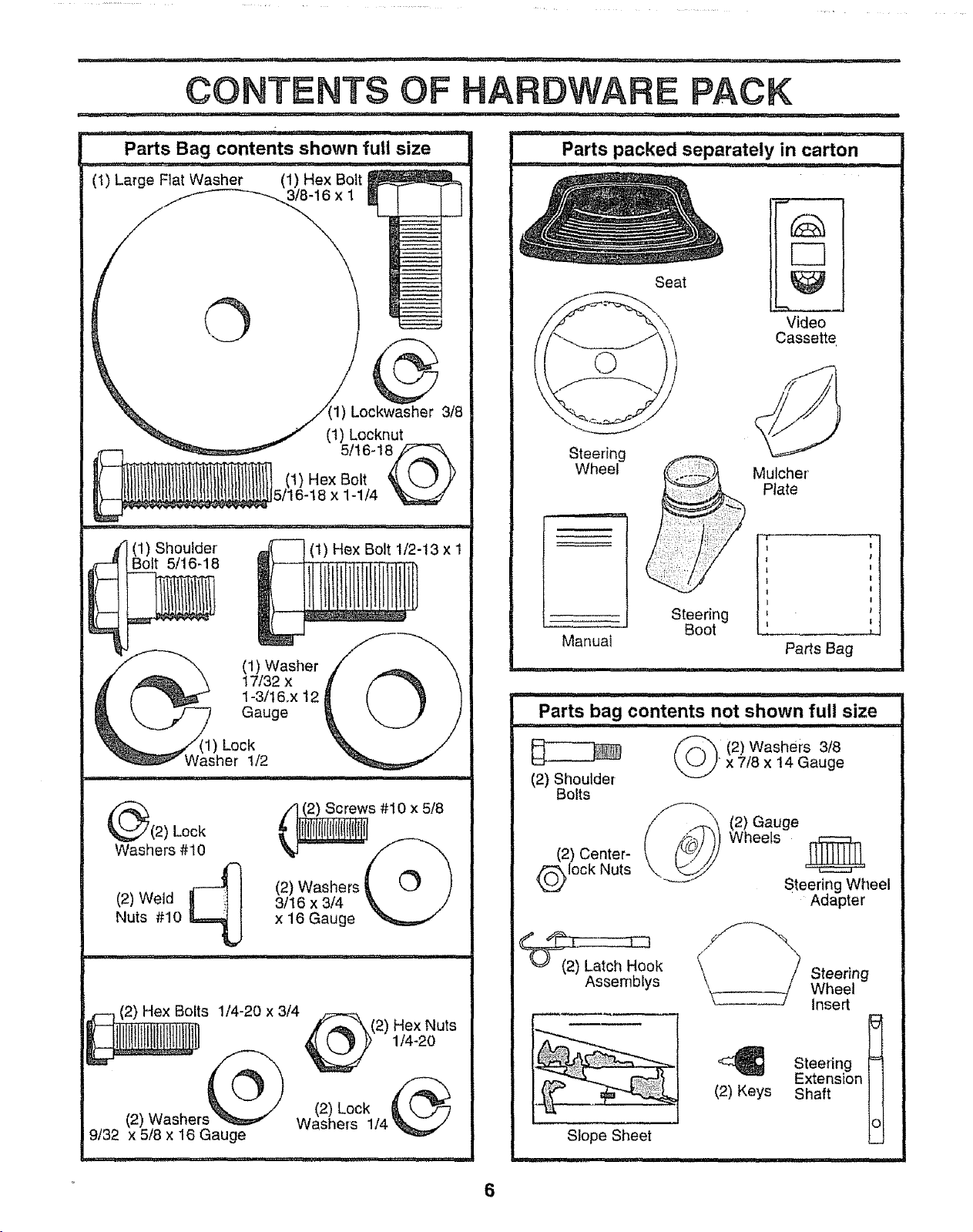
CONTENTS OF
Parts Bag contents shown full size
(1) Large Flat Washer (1) Hex Bolt
Seat
Video
Cassette
c_3t8
_ (1) Locknut
5/t 6-18_
(1) Hex Bolt _, k,....} ,y
i !l,, ,,i i,I _ L U ,, J, m
(1) Shoulder
Bolt 5/16-18
11)Lock
Washer 1/2
.u.i.i . i.u. i. ii.
_(2) Lock _s #I0 x 5/8
Washers #10
(2) Weld 3/16 x 3/4
Nuts #10 x 16 Gauge
5/16-18 x 1-1/4 _
(1) Hex Bolt 1/2-13 x I
(1) Washer
t7/32 x
1-3/t6.x 12
Gauge
(2) Washers t
Steering
Wheel
Steering
Manual
Parts bag contents not shown full size
(2} Shoulder
Bolts
(2) Center-
lock Nuts
Boot
__1(2) GaugeWheels _
Mulcher
Plate
H
Parts Bag
(2) Washers 3/8•x 7/8 x 14 Gauge
Steering Wheel
Adapter
r-m (2) Hex Bolts 1/4-20 x 3/4
(2) Washer Washers 1/4
9/32 x 5/8 x 16 Gauge
%
f,,_"_(2) Hex Nuts
(2) Lock
_ok
Assemblys
(2) Keys
Slope Sheet
Steering
Wheel
Insert
Steering =
Extension
Shaft
O
6
ASSEMBLY
.......... = , ........ N'U',NHm ..... I
Your new tractor has been assembled at the factory with exception of those parts left unassembfed for shipping purposes,
To ensure safe and proper operation ofyour tractor all parts and hardware you assemble must be tightened securely, Use
the correct tools as necessary to insure proper tightness,
TOOLS REQUIRED FOR ASSEMBLY
INSERT
A socket wrench set will make assembly easier Standard
wrench sizes are listed
(1) 9/16" wrench
(2) 7/16" wrenches
(2) 1/2" wrench
(1) 3/4" wrench
When right or left hand is mentioned in this manual, it
means when you are in the operating position (seated
behind the steering wheel).
(1) 3/4" Socket w/drive rachet
Phillips Screwdriver
Tire pressure gauge
Utility knife
Pliers
TO REMOVE TRACTOR FROM CARTON
UNPACK CARTON
o Remove all accessible loose parts and p&rts cartons
from carton (See page 6).
o Cut, from top to bottom, along lines on allfour corners
of carton, and lay panels flato
• Check for any additional loose parts or cartons and
remove.
_. , y 3/8 HEX BOLT
STEERING
WHEEL _, STEERING
EXTE.S!OH
s.AFT
i
'ii 3tB LOCK
'_""""'- WASHER
I...... WASHER
" < \V"
_..._/,.( _ ADAPTER
..... 11 5/16 HEX
•=... LARGE FLAT
BEFORE ROLLING TRACTOR OFF SKID
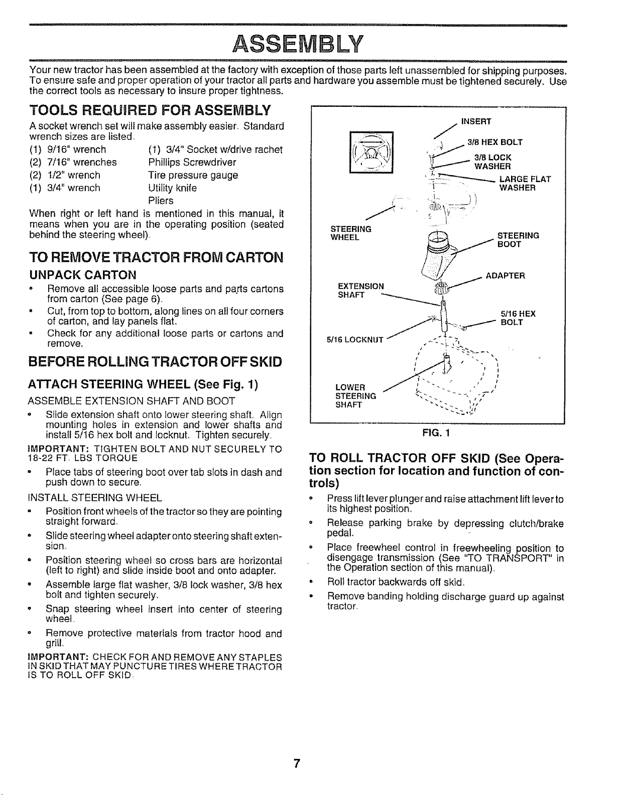
ATTACH STEERING WHEEL (See Fig. 1)
ASSEMBLE EXTENSION SHAFT AND BOOT
• Slide extension shaft onto lower steering shaft° Align
mounting holes in extension and lower shafts and
install 5/16 hex bolt and locknut. Tighten securely..
IMPORTANT: TIGHTEN BOLT AND NUT SECURELY TO
t8_22 FT, LBS TORQUE
= Place tabs of steering boot over tab slots in dash and
push down to secure.
INSTALL STEERING WHEEL
= Position front wheels of the tractor so they are pointing
straight forward°
• Slide steering wheel adapter onto steering shaft exten-
sion.
° Position steering wheel so cross bars are horizontal
(left to right) and slide inside boot and onto adapter°
• Assemble farge flat washer, 3/8 lock washer, 3/8 hex
bolt and tighten securely,
• Snap steering wheel insert into center of steering
wheel
o Remove protective materials from tractor hood and
grill
IMPORTANT: CHECK FOR AND REMOVE ANY STAPLES
IN SKiD THAT MAY PUNCTURE TIRES WHERE TRACTOR
IS TO ROLL OFF SKID
1 #
LOWER , ./
STEERING _,-. - - -, - T
SHAFT "-.". ',_'
FIG. 1
TO ROLL TRACTOR OFF SKID (See Opera-
tion section for location and function of con-
trols)
• Press liftleverplunger and raise attachment lift lever to
its highest position.,
o Release parking brake by depressing clutch/brake
pedal.
o Place freewheel control in freewheeling position to
disengage transmission (See 'q'O TRANSPORT" in
the Operation section of this manual),
o Roll tractor backwards off skid,
• Remove banding holding discharge guard up against
tractor_
7
=,,i,
, i, ==, ,=,=,,=1=.....................
ASSEMBLY
HOW TO SET UP YOUR TRACTOR
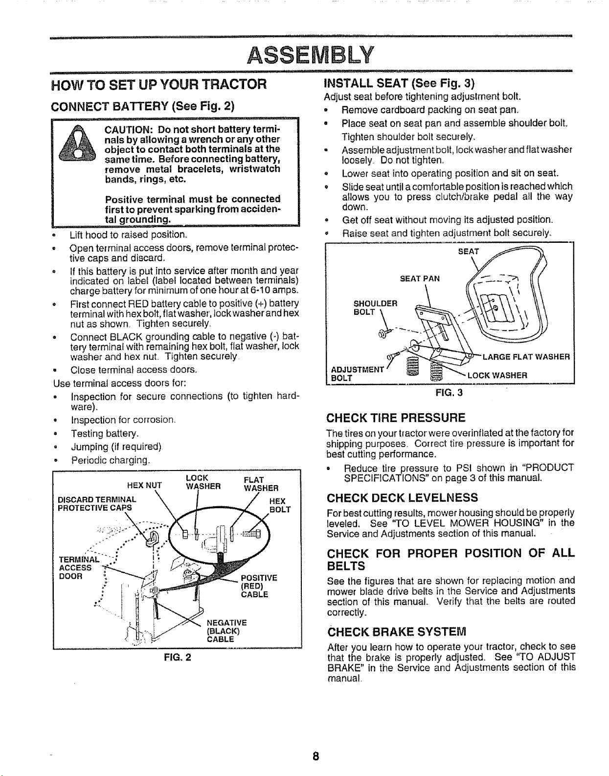
CONNECT BATTERY (See Fig. 2)
......... q,, ,,,,, i .... p,i ,111..... i ,i,,,,,iI , rq,
A CAUTION: Do not short battery termi-
Lift hood to raised position_
= Open terminal access doors, remove terminal protec-
tive caps and discard°
o if this battery is put into service after' month and year
indicated on label (label located between terminals)
charge battery for minimum of one hour at 6-10 amps_
• First connect RED battery cable to positive (+) battery
terminal with hex bolt, flat washer, lock washer and hex
nut as shown Tighten securely.
o Connect BLACK grounding cable to negative (-) bat-
tery terminat with remaining hex bolt, flat washer, lock
washer and hex nuL Tighten securely
, Close terminal access doors.
Use terminal access doors for:
° Inspection for secure connections (to tighten hard-
ware).
• inspection for corrosion..
• Testing battery.
, Jumping (if required)
• Periodic charging°
DISCARD TERMINAL HEX
PROTECTIVE CAPS BOLT
nals by allowing a wrench or any other
object to contact both terminals at the
sametime. Before connecting battery,
remove metal bracelets, wristwatch
bands, rings, etc.
Positive terminal must be connected
first to prevent sparking from acciden-
ta! grounding. . .........
LOCK FLAT
HEX NUT WASHER WASHER
INSTALL SEAT (See Fig. 3)
AdjUst seat before tightening adjustment bolt.
• Remove cardboard packing on seat pan°
= Place seat on seat pan and assemble shoulder bolt,
Tighten shoulder bolt securely.
= Assemble adjustment bolt, lock washerand flat washer
toosely. Do not tighten°
,, Lower seat into operating position and sit on seat.
• Slide seat untila comfortable position isreached which
allows you to press clutch/brake pedal all the way
down_
° Get off seat without moving its adjusted position.
,, Raise seat and tighten adjustment bolt securely..
SEAT
SEAT PAN
SHOULDER
BOLT_._.
BOLT
FIG. 3
CHECK TIRE PRESSURE
The tires on your tractor were ovednflated at the factory for
shipping purposes. Correct tire pressure is important for
best cutting performance.
= Reduce tire pressure to PSI shown in "PRODUCT
SPECIFICATIONS" on page 3 of this manual.
CHECK DECK LEVELNESS
For best cutting results, mower housing shoutd be properly
leveled, See "TO LEVEL MOWER HOUSING" in the
Service and Adjustments section of this manual.
TERM|NAL ....
ACCESS
DOOR ,_,
FIG. 2
NEGATIVE
(BLACK)
CABLE
POSITIVE
(RED)
CABLE
CHECK FOR PROPER POSITION OF ALL
BELTS
See the figures that are shown for replacing motion and
mower blade drive belts in the Service and Adjustments
section of this manual.. Verify that the belts are routed
correctiy.
CHECK BRAKE SYSTEM
After you learn how to operate your tractor, check to see
that the brake is properly adjusted_ See "TO ADJUST
BRAKE" in the Service and Adjustments section of this
manual.
8
ASSEMBLY
=
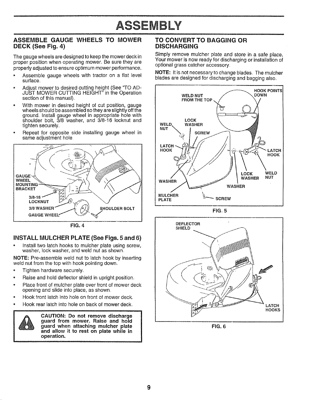
ASSEMBLE GAUGE WHEELS TO MOWER
DECK (See Fig. 4)
The gauge wheefs are designed to keep the mower deck in
proper position when operating mower. Be sure they are
properly adjusted to ensure optimum mower performance.
o Assemble gauge wheels with tractor on a flat teve!
surface.
o Adjust mower to desired cutting height (See 'q'O AD-
JUST MOWER CUTTING HEIGHT" in the Operation
section of this manua0..
o With mower in desired height of cut position, gauge
wheels should be assembled so they are slightly off the
ground_ Install gauge wheel in appropriate hole with
shoulder bolt, 3/8 washer, and 3/8-16 locknut and
tighten securely..
- Repeat for opposite side installing gauge wheel in
same adjustment hole
TO CONVERT TO BAGGING OR
DISCHARGING
Simpty remove mulcher plate and store in a safe place.
Your mower is now ready for discharging or installation of
optional grass catcher accessory.
NOTE: It is not necessary to change blades. The mulcher
blades are designed for discharging and bagging alsoo
HOOK POINTS
WELD NUT
WELD. WASHER
NUT _
LATCH
HOOK
LOCK
,_ SCREW
\
DOWN
LATCH
HOOK
WHEEL
BRACKET
318-1
LOCKNUT
318WASHER .,,.41/tZ /. )] SHOULDER BOLT
GAUGE WHEEL: _ _"
J k.y/"
FIG, 4
INS'fALL MULCHER PLATE (See Figs. 5 and 6)
o Install two latch hooks to mulcher plate using screw,
washer, Iock washer, and weld nut as shown
NOTE: Pre-assembte weld nut to latch hook by inserting
weld nut from the top with hook pointing down.
o Tighten hardware securetyo
° Raise and hold deflector shield in upright position.
. Place front of mulcher plate over front of mower deck
opening and slide into place, as shown
= Hook front latch into hole on front of mower deck,
- Hook rear latch into hole on back of mower deck°
WASHER
MULCHER
PLATE
DEFLECTOR
SHIELD
WASHER
SCREW
FIG, 5
LOCK
WASHER
WELD
NUT
LATCH
HOOKS
guard from mower, Raise and hold
CAUTION: Do not remove discharge
guard when attaching mulcher plate
and allow it to rest on plate while in
operation,
FIG. 6
9
 Loading...