

Page 1

C
®
MODEL NUMBER 917.259565
• Assembly
• Operation
• Customer Responsibilities
• Service and Adjustments
• Repair Parts
OWNER'S MANUAL
For answers to your questions
about this product, Call:
1-800-659-5917
Sears Craftsman Help Line
5 am - 5 pro, Mot) - Sat
CAUTION: Read and follow all safety rules and instructions before operating this equipment.
FOR CONSUMER ASSISTANCE HOT LINE, CALL THIS TOLL FREE NUMBER: 1-800-659-5917
m_
Page 2
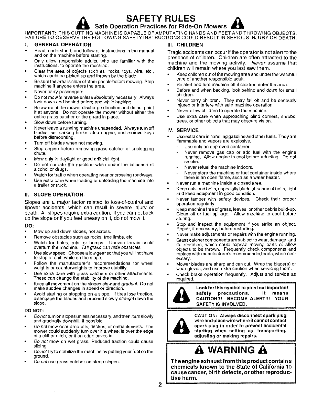
Safe Operation Practices for Ride-On Mowers
IMPORTANT: THIS CUTTING MACHINE IS CAPABLE OFAMPUTATING HANDS AND FEET AND THROWING OBJECTS.
FAILURE TO OBSERVE THE FOLLOWING SAFETY INSTRUCTIONS COULD RESULT IN SERIOUS iNJURY OR DEATH.
I. GENERAL OPERATION
• Read, understand, and follow all instructions in the manual
and on the machine before slarting.
• Only allow responsible adults, who are familiar with the
instructions, to operate the machine.
• Clear the area of objects such as rocks, toys, wire, etc.,
which could be picked up and thrown by the blade.
• Be sure the area is clear of other people before mowing. Stop
machine if anyone enters the area.
• Never carry passengers.
• Do not mow in reverse unless absolutely necessary. Always
look down and behind before and while backing.
• Be aware of the mower discharge direction and do net point
it at anyone. Do not operate the mower without either the
entire grass catcher or the guard in place.
• Slow down before turning.
• Never leave a running machine unattended. Always turn off
blades, set parking brake, stop engine, and remove keys
before dismounting.
• Turn off blades when not mowing.
• Stop engine before removing grass catcher or unclogging
chute.
• Mow only in daylight or good artificial light.
• Do not operate the machine while under the influence of
alcohol or drugs.
• Watch for traffic when operating near or crossing roadways.
° Use extra care when loading or unloading the machine into
a trailer or truck.
II. SLOPE OPERATION
Slopes are a major factor related to loss-of-control and
tipover accidents, which can result in severe injury or
death. All slopes require extra Caution. Ifyou cannot back
up the slope or if you feel uneasy on it, do not mow it.
DO:
• Mow up and down slopes, not across.
° Remove obstacles such as rooks, tree limbs, etc.
• Watch for holes, ruts, or bumps. Uneven terrain could
overturn the machine. Tall grass can hide obstacles.
• Use slow speed. Choose a low gear so that you will not have
to stop or shift while on the slope.
• Follow the manufacturer's recommendations for wheel
weights or counterweights to improve stability.
• Use extra care with grass catchers or other attachments.
These can change the stability of the machine.
• Keep all movement on the slopes slowand gradual Do not
make sudden changes in speed or direction.
• Avoid starting or stopping on a slope. If tires lose traction,
disengage the blades and proceed slowly straight down the
slope.
DO NOT:
• Donot turn on slopes unless necessary, andthen, turn slowly
and gradually downhill, if possibIe.
° Do not mow near drop-offs, ditches, or embankments. The
mower could suddenly turn over if a wheel is over the edge
of a cliff or ditch, or if an edge caves in.
• Do not mow on wet grass. Reduced traction could cause
sliding.
• Do not try to stabilize the machine by putting your foot on the
ground.
• Do not use grass catcher on steep slopes.
SAFETY RULES
III. CHILDREN
Tragic accidents can occur if the operator is not alert to the
presence of children. Children are often attracted to the
machine and the mowing activity, Never assume that
children will remain where you last saw them.
° Keep children out of the mowing area and under the watchful
care of another responsible adult.
• Be alert and turn machine off if children enter the area.
• Before and when backing, look behind and down for small
children.
• Never carry children. They may fall off and be seriously
injured or interfere with safe machine operation.
° Never allow children to operate the machine.
° Use extra care when approaching blind corners, shrubs,
trees, or other objects that may obscure vision.
IV. SERVICE
• Use extracare inhandling gasoline and other fuels. They are
flammable and vapors are explosive.
Use only an approved container.
Never remove gas cap or add fuel with the engine
running. Allow engine to cool before refueling. Do not
smoke.
Never refuel the machine indoors.
Never store the machine or fuel container inside where
there is an open flame, such as a water heater.
• Never run a machine inside a closed area.
• Keep nuts and bolts, especially btade attachment bolts, tight
and keep equipment in good condition.
• Never tamper with safety devices. Check their proper
operation regularly.
• Keep machine free of grass, leaves, orother debds build-up.
Clean oil or fuel spillage. Allow machine to cool before
storing.
• Stop and inspect the equipment if you strike an object.
Repair, if necessary, before restarting.
• Never make adjustments or repairs with the engine running.
° Grass catcher components are subject towear, damage, and
deterioration, which could expose moving parts or altow
objects to be thrown. Frequently check components and
replace with manufacturer's recommended parts, when nec-
essary.
• Mower blades are sharp and can cut. Wrap the blade(s) or
wear gloves, and use extra caution when servicing them.
• Check brake operation frequently. Adjust and service as
required.
A wire and place wire where it cannot contact I
The engine exhaust from this product contains
safety precautions. It means
Look for this symbol to point out important
CAUTION!l! BECOME ALERT!!! YOUR
SAFETY IS INVOLVED.
CAUTION: Always disconnect spark plug I
spark plug in order to prevent accidental I
starting when setting up, transporting, I
adjusting or making repairs,
WARNING
chemicals known to the State of California to
cause cancer, birth defects, or other reproduc-
tive harm.
2
I
Page 3

CONGRATULATIONS on your purchase of a Sears
Tractor. it has been designed, engineered and manufac-
tured to give you the best possible dependability and
performance.
Should you experience any problem you cannot easily
remedy, please contact your nearest Sears Authorized
Service Center/Department. We have competent, well-
trained technicians and the proper tools to service or repair
this tractor.
Please read and retain this manual. The instructions will
enable you to assemble and maintain your tractor properly.
Always observe the "SAFETY RULES".
MODEL
NUMBE R 917.259565
SERIAL
NUMBER
DATE OF PURCHASE
THE MODEL AN D SERIAL NUMBERS WILL BE FOUND
i ON A PLATE UNDER THE SEAT.
YOU SHOULD RECORD BOTH SERIAL NUMBER AND
DATE OF PURCHASE AND KEEP IN A SAFE PLACE
FOR FUTURE REFERENCE.
MAINTENANCE AGREEMENT
A Sears Maintenance Agreement is available on this prod-
uct. Contact your nearest Sears store for details,
CUSTOMER RESPONSIBILITIES
• Read and observe the safety rules.
o Foltow a regular schedule in maintaining, caring for and
using your tractor.
- Follow the instructions under"Customer Responsibili-
ties" and "Storage" sections of this owner's manual.
WARNING: This tractor is equipped with an internal
combustion engine and should not be used on or near any
unimproved forest-covered, brush-covered or grass-cov-
ered land unless the engine's exhaust system is equipped
PRODUCT SPECIFICATIONS
HORSEPOWERi 19.5
GASOLINE CAPACITY 3°5 GALLONS
AND TYPE: UNLEADED REGULAR
OiL TYPE (APt-SF/SG/SH): SAE 30 (above 32°F)
SAE 5W-30 (below 32°F)
OIL CAPACITY: 3.0 PINTS
SPARK PLUG: CHAMPION RJ19LM
(GAP: .030")
VALVE CLEARANCE: iNTAKE: .004" - .006"
EXHAUST: °007" - .009"
GROUND SPEED (MPH): FORWARD:
1st 1.1
2rid 1,4
3rd 2.3
4th 3.5
5th 4.5
6th 5.7
REVERSE: 1.8
TIRE PRESSURE: FRONT: 14 PS!
REAR: 10 PSI
CHARGING SYSTEM: 3 AMPS BATTERY
5 AMPS HEADLIGHTS
BATTERY: AMP/HR: 30
MIN. CCA: 240
CASE SIZE: U1R"
BLADE BOLT TORQUE: 30-35 FT. LBS.
with a spark arrester meeting applicable local or state laws
(if any). If a spark arrester is used, it should be maintained
in effective working order by the operator.
In the state of California the above is required by law
(Section 4442 of the California Public Resources Code),
Other states may have similar laws. Federal laws apply on
federal lands. A spark arrester for the muffler is available
through your nearest Sears Authorized Service Center/
Department (See REPAIR PARTS section of this manual).
LIMITED TWO YEAR WARRANTY ON CRAFTSMAN RIDING EQUIPMENT
For two (2) years from the date of purchase, if this Craftsman Riding Equipment is maintained, lubricated and tuned up according
to the instructions in the owner's manual, Sears will repair or replace, free of charge, any parts found to be defective in material or
workmanship.
This Warranty does not cover:
Expendable items which become worn during normal use, such as blades, spark plugs, air cleaners, belts, etc:
• Tire replacement or repair caused by punctures from oulside objects, such as nails, thorns, stumps, or glass.
Repairs necessary because of operator abuse, negligence, improper storage or accident or the failure to maintain the
equipment according to the instructions contained in the owner's manual.
• Riding equipment used for commercial or rental purposes.
LIMITED 90 DAY WARRANTY ON BATTERY
For ninety (90) days from date of purchase, if any battery included with this riding equipment proves defective in material or
workmanship and our testing determines the battery will not hold a charge, Sears will replace the battery at no charge.
IN-HOME WARRANTY SERVICE ON YOUR CRAFTSMAN RIDING EQUIPMENT IS AVAILABLE AT NO-CHARGE FOR 30
DAYS FROM THE DATE OF PURCHASE. PLEASE CONTACT YOUR NEAREST SERVICE CENTER. AFTER 30 DAYS FROM
THE DATE OF PURCHASE, WARRANTY SERVICE IS AVAILABLE BY TAKING YOUR CRAFTSMAN RIDING EQUIPMENT TO
YOUR NEAREST SEARS SERVICE CENTER. (iN-HOME WARRANTY SERVICE WILL STILL BE AVAILABLE AFTER 30 DAYS
FROM THE DATE OF PURCHASE BUT A STANDARD TRIP CHARGE WILL APPLY.) THIS WARRANTY APPLIES ONLY
WHI LE THIS PRODUCT IS IN THE UNITED STATES.
This Warranty gives you specific lega! rights, and you may also have other rights which may vary from state to state.
SEARS, ROEBUCK AND CO., D/817 WA, HOFFMAN ESTATES, IL 60179
3
Page 4
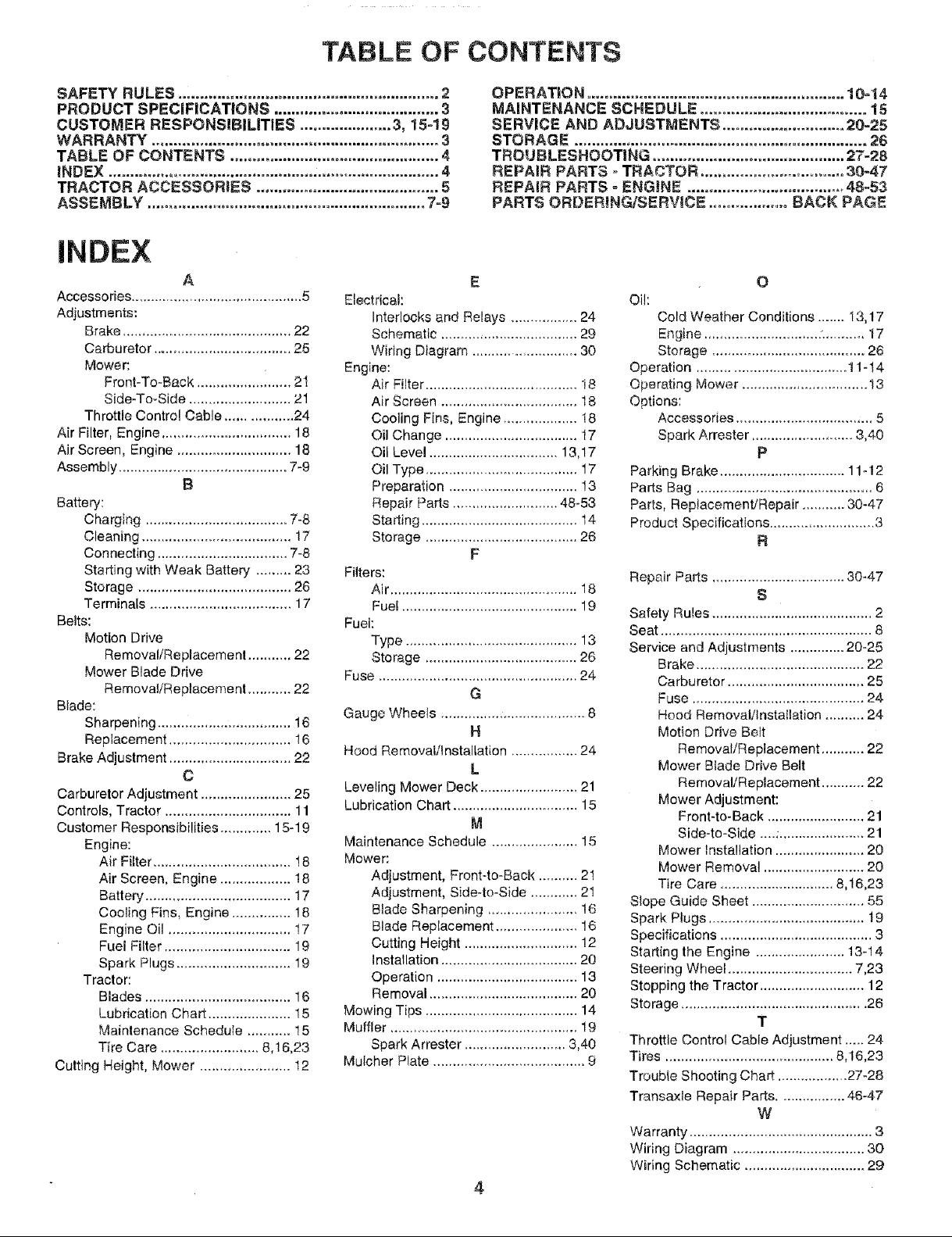
TABLE OF CONTENTS
SAFETY RULES ............................................................ 2
PRODUCT SPECIFICATIONS ...................................... 3
CUSTOMER RESPONSIBILITIES ..................... 3, 15-19
WARRANTY .................................................................. 3
TABLE OF CONTENTS ................................................ 4
INDEX ............................................... ,............................ 4
TRACTOR ACCESSORIES .......................................... 5
ASSEMBLY ................................................................ 7-9
INDEX
A
Accessories ............................................ 5
Adjustments:
Brake ........................................... 22
Carburetor ................................... 25
Mower'.
Front-To-Back ................. i...... 21
Side-To-Side .......................... 21
Throttle Control Cable ................. 24
Air Filter, Engine ................................. 18
Air Screen, Engine ............................ 18
Assembly ........................................... 7-9
B
Battery:
Charging .................................... 7-8
Cleaning ...................................... 17
Connecting ................................. 7-8
Starting with Weak Battery ......... 23
Storage ....................................... 26
Terminals .................................... 17
Belts:
Motion Drive
Removal/Replacement ........... 22
Mower Blade Drive
Remova!/Replacement ........... 22
Blade:
Sharpening .................................. 16
Replacement ............................... 16
Brake Adjustment ............................... 22
C
Carburetor Adjustment ....................... 25
Controls, Tractor ................................ 11
Customer Responsibilities ............. 15-19
Engine:
Air FiLter................................... t 8
Air Screen, Engine .................. 18
Battery ..................................... 17
Cooling Fins, Engine ............... 18
Engine Oil ............................... 17
Fuel Filter ................................ 19
Spark Plugs ............................. 19
Tractor:
Blades ..................................... 16
Lubrication Chart ..................... 15
Maintenance Schedule ........... 15
Tire Care ......................... 8,16,23
Cutting Height, Mower ....................... t2
Electrical:
Interlocks and Relays ................. 24
Schematic ................................... 29
Wiring Diagram .......................... 30
Engine:
Air Filter ....................................... 18
Air Screen .................................. 18
Cooling Fins, Engine ................... 18
Oil Change .................................. 17
Oil Level ................................. 13,17
Oil Type ....................................... 17
Preparation ................................. !3
Repair Parts ........................... 48-53
Starting ....................................... 14
Storage ....................................... 26
Filters:
Air ................................................ 18
Fuel ............................................. 19
Fuel:
Type ............................................ 13
Storage ....................................... 26
Fuse ................................................... 24
Gauge Wheels .................................... 8
Hood Removal/Installation ................. 24
Leveling Mower Deck ......................... 21
Lubrication Chart ................................ 15
Maintenance Schedule ...................... 15
Mower:
Adjustment, Front-to-Back .......... 2I
Adjustment, Side-to-Side ............ 2t
Blade Sharpening ....................... 16
Blade Replacement ..................... 16
Cutting Height ............................. 12
Installation ................................... 20
Operation .................................... 13
Removal ...................................... 20
Mowing Tips ....................................... 14
Muffler ............................................... 19
Spark Arrester .......................... 3,40
Mulcher Plate ....................................... 9
OPERATION ........................................................... 10=14
MAINTENANCE SCHEDULE ...................................... 15
SERVICE AND ADJUSTMENTS ............................ 20-25
STORAGE ................................................................... 26
TROUBLESHOOTING ............................................ 27-28
REPAIR PARTS - TRACTOR .................................. 30-47
REPAIR PARTS oENGINE .................................... 48-53
PARTS ORDERING!SERVICE .................. BACK PAGE
E
Oil:
Cold Weather Conditions ....... I3,17
Engine ............................ :........... 17
Storage ....................................... 26
Operation .................................... t 1-14
Operating Mower ................................ t3
Options:
Accessories ............................... ,,, 5
Spark Arrester .......................... 3,40
Parking Brake ................................ 11-12
Parts Bag ............................................. 6
Parts, Rep_acemenVRepair ........... 30-47
Product Specifications ........................... 3
F
Repair Parts .................................. 30-47
Safety Rules ......................................... 2
Seat ...................................................... 8
Service and Adjustments .............. 20-25
Brake ........................................... 22
G
H
L
M
Carburetor ................................... 25
Fuse ........................................... 24
Hood Removal/Installation .......... 24
Motion Drive Belt
Removal/Replacement ........... 22
Mower Blade Drive Belt
Removal/Replacement ........... 22
Mower Adjustment:
Front-to-Back ......................... 21
Side-to-Side ....:...................... 21
Mower Installation ....................... 20
Mower Removal .......................... 20
Tire Care ............................. 8,16,23
Slope Guide Sheet ............................. 55
Spark Plugs ........................................ 19
Specifications ....................................... 3
Starting the Engine ....................... 13-14
Steering Wheel ................................ 7,23
Stopping the Tractor ........................... 12
Storage ............................................... 26
Throttle Control Cable Adjustment ..... 24
Tires ........................................... 8,16,23
Trouble Shooting Chart .................. 27_28
Transaxle Repair Parts ................. 46-47
Warranty ............................................... 3
Wiring Diagram .................................. 30
Wiring Schematic ............................... 29
O
P
R
S
T
W
4
Page 5
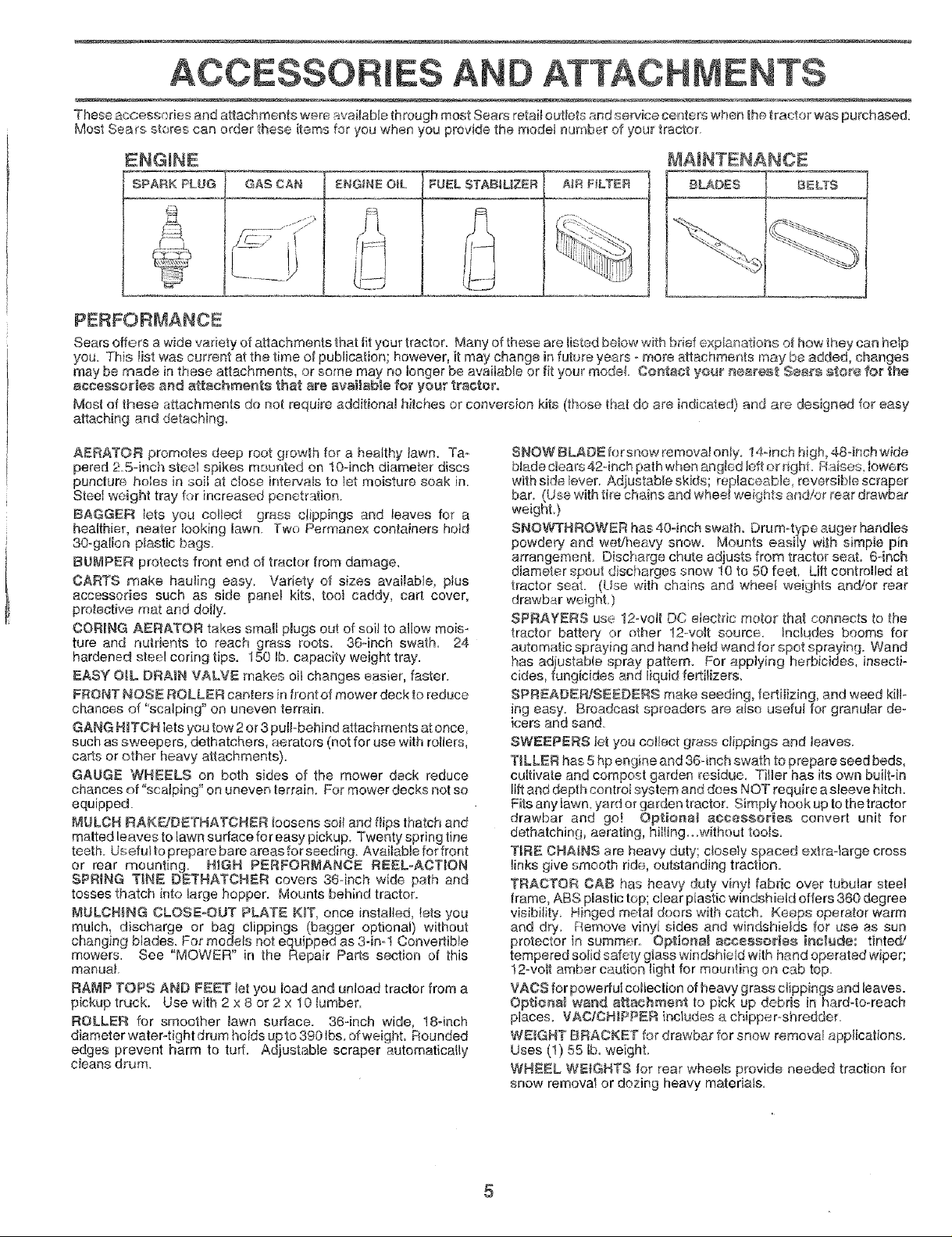
IES
"Theseaccessories and attachments were available through most Seers retait outlets end service centers when the tractor was purchased:
Most Sears stores can order these items for you when you provide the model number of your tractor,
ENGINE
SPARK PLL_G GAg CAN ENGINEOiL FUEL STABtUZER AJR FtLTEFI BLADES BELTS
PERFORMANCE
Sears offers a wide variety of attachments that fit your tractor. Many of these are Iisted be!ow with brief explanatio_-_eof how they can help
you. This list was current at the time of puMicafion; however, it may change in future years - more attachments may be added, changes
may be made in these attachments, or some may no longer be avaitab{e or fit your model Contacl yo_ r_arest See_'s store for the
accessories and attachments that are available for your tractor.
Most of these attachments do not require additional hitches or conversion kits (those that do are indicated) and are designed for easy
attaching and detaching,
AERATOR promotes deep root growth for a healthy' lawn. Ta-
pered 2.5-inch steei spikes mounted on 10-inch diameter discs
puncture holes in soil at close intervals to let moisture soak in.
Steel weight tray for increased penetration.
BAGGER lets you collect grass clippings and leaves for a
healthier, nearer looking iawn Two Permanex containers hold
30-gallon plastic bags.
BUMPER protects front end of tractor from damage.
CARTS make hauling easy. Variety of sizes avai}able, pius
accessories such as side pane_ kits, toot caddy, cart cover,
protective mot and deity.
COR_NG AERATOR takes small plugs out of soil to allow mois-
ture and nutrients to reach grass roots. 36qnch swath. 24
hardened steel coring tips. 150 lb. capacity weight tray.
EASY O_L.DRAIN VALVE makes oil changes easier, faster.
FRONT NOSE ROLLER canters infront of mower deck to reduce
chances of "sca_ping" on uneven terrain.
GANG H_TCH lets you tow 2 or 3 putt-behind attachments at once,
such as sweepers, dethatchers, aerators (not for use with rollers,
carts or other heavy attachments).
GAUGE WHEELS on both sides of the mower dock reduce
chances of "scalping" on uneven terrain. For mower decks not so
equipped.
MULCH RAKE/DETHA'FCHER loosens soil and flips thatch and
malted leaves to [awn surface for easy pickup. Twenty spring fine
teeth. Usefultopreparebaroareasforseeding. Available for front
or rear mounting. H_GR PERFORMANCE REEL-ACTION
SPRING T_NE OETRATCNER covers 36-inch wide path and
tosses thatch into large hopper. Mounts behind tractor.
MULCHNG CLOSE-OUT PLATE K_T, once installed, lets you
mulch, discharge or bag clippings (bagger optional) without
ch_._ngingblades. For models not equipped as 3-inol Convertible
mowers. See "MOWER" in the Repair Parts section of this
manual
RAMP TOPS AND FEET Jet you load and unload tractor from a
pickup truck. Use with 2 x 8 or 2 x 10 lumber.
ROLLER for smoother Jawn surface. 36-inch wide, 18-inch
diameter water4ight drum holds upto 390 lbs. of weight. Rounded
edges prevent harm to tuff. Adjustable scraper automatically
c_eans drum,
SNOWBLADEforsnowmmova!on_y. 14-inch high,484nchwide
blade clears 42-inch path when angled left or right Raises_ lowers
with side lever, Adiustable skids; _eplaceabie reversible Scraper
bar. (Use with tire chains and wheel weights a_ld/or rear drawbar
weight.)
SNOWTHROWER has 40qnch swath, Drum-type auger handles
powdery and we_Jheevy snow. Mounts easiiy wi_h simple pin
a_rangement. Discharge chute adjusts from tractor seat. 64nch
diameter spout disct_arges snow 10 to 50 feet. Lift controlled at
tractor seat. (Use with chains and wheel weights and!or rear
drawbar weight,)
SPRAYERS use 12-vott DO etectdc motor that connects to the
tractor battery or other 12-vo_t source. Includes booms for
automatic spraying and hand hetd wand for spot spraying. Wand
has adiustable spray pattern. For applying herbicides, insecti-
cides, fungicides and liquid fertilizers,
SPREADE_S_DERS make seeding, fertilizing, and weed kill-
ing easy. Broadcast spreaders are a_so useful for granular de-
icers and sand.
SWEEPERS Jetyou coltect grass c|ippings and leaves.
T_LLER has 5 hp engine and 36-inch swath to prepare seed beds,
cultivate and compost garden residue. Tiller has its own built-in
lift and depth control system and does NO'[ require a sleeve hitch.
Fits any lawn, yard or garden tractor. Simpty hook up to the tractor
drawbar and go! Optional accessories convert unit for
dethatching, aerating, hilling_,,without toots.
TIRE CHAINS are heavy duty; c_ose_yspaced extraolarge cross
links give smooth ride, outstanding traction.
TRACTOR CAB has heavy duty vinyl fabdc over tubular steel
frame, ABS plastic top; clear plastic windshield offers 360 degree
visibility, Hinged metal doors with catch_ Keeps operator warm
and dry. Remove vinyi sides and windshields for use as sun
protector in summer. Optiona! accessories ir_c_ude: tinted!
tempered solid safety glass windshield with hand operated wiper;
12-vott amber caution light for mounting on cab top.
VACS for powedu{ collection ofheavy grass clippings and leaves.
Opt_o_a_ wand a_achme_t to pick up debris in hard4o-reach
places. VAC/CN_PRER includes e chipper_shredder.
WEIGHT BRACKET for drawbar for snow removal applications.
Uses (!) 55 Iboweight.
WHE_L WEIGHTS {or rear wheels provide needed traction for
snow remova! or dozing heavy materials.
5
Page 6
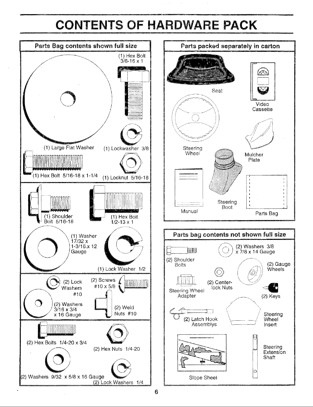
CONTENTS OF HARDWA PACK
Parts Bag contents shown full size
(1) Hex Bolt
3/8-16 x 1
\
o i
/
(1) Large Flat Washer (1) Lockwasher 3/8
(1) Hex Bolt 5/16-18 x 1-1/4 (1) kocknut 5/16-18
Parts packed separately in carton
Seat
Video
Cassette
Steering
Wheel Mulcher
Plate
I"' Bolt 5/16-18 1/2-13x 1
_. Washers
_/ \ #10
L _ )(2) Washers
_. / 3/16 x3/4
(2) Hex Bolts 1/4-20 x 3/4
._(2) Lock
x 16 Gauge
r (1) Hex Bolt
17/32 X -_
(1)Washer d( (A_," i
1-3/16.x 12
Gauge _/" /
(1) Lock Washer 1/2
#10 x 5/8
(2) Screws
(2) Weld
Nuts #10
Steering
Manua_
Parts bag contents not shown full size
(2) Shoulder
Bolts
Steering Wheel
Adapter
2) Latch Hook
Assemblys
Boot
(2) Center-
lock Nuts
" / Steering
Parts Bag
(2) Washers 3/8
x 7/8 x 14 Gauge
/
L
J ......... -,, (2) Keys
\/ /
,_ 1 Insert
........../ Wheel
(2) Gauge
Wheels
(2) Hex Nuts 1/4-20
[2) Washers 9/32 x 5/8 x 16 Gauge
Lock Washers 1/4
Slope Sheet
Extension
Steering
Shaft
Page 7
ASSEM
Your new tractor has been assembled at the factory with exception of those paris left unassembied for shipping purposes_
To ensure sate and proper operation of your tractor all parts and hardware you assemble must be tightened securely. Use
the correct tools as necessary lo insure proper tightness.
TOOLS REQUIRED FOR ASSEMBLY
A socket wrench set witt make assembly easier. Standard
wrench sizes are listed
(1} 3/4" Socket w/drive rachet
(2) 7/16" wrenches Phillips Screwdriver
(2) 1/2" wrenches Tire pressure gauge
(t) 9/t6 _wrench Utility knife
When right or left hand is mentioned in this manual, it
means when you are in the operating position (seated
behind the steering wheel).
TO REMOVE TRACTOR FROM CARTON
UNPACK CARTON
Remove all access#ble toose parts and parts cartons
from carton (See page 6).
,, Cut, _rom top to bottom, along lines on all four corners
of carton, and lay panels flat.
,, Cheek for any additional toose parts or cartons and
remove
BEFORE ROLUNG TRACTOR OFF SKID
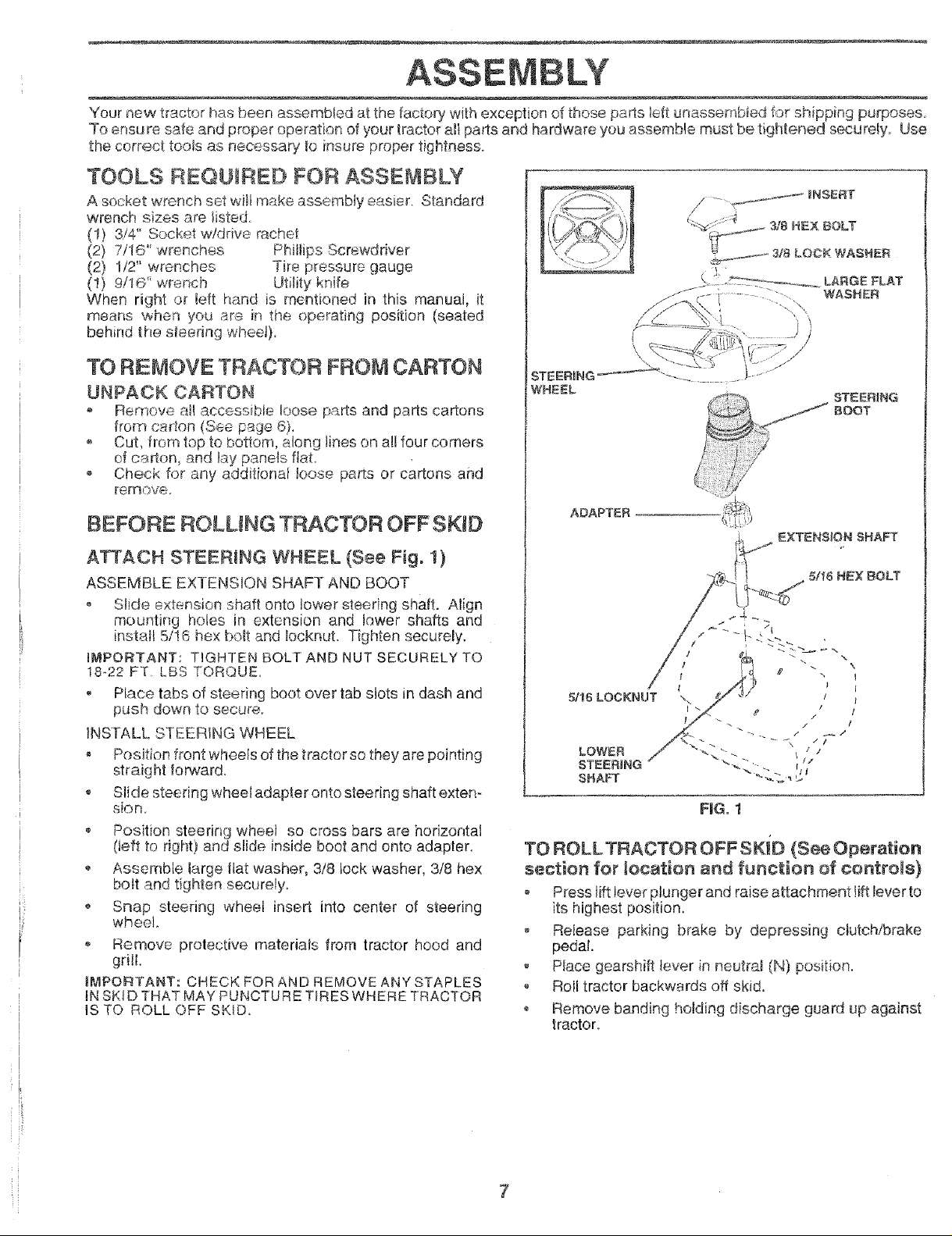
A_ACH STEERING WHEEL {See Fig. 1)
ASSEMBLE EXTENSION SHAFT AND BOOT
Slide extension shaft onto lower steering shaft. Align
mounting holes in extension and lower shafts and
install 5/!6 he× bolt and Iocknut. Tighten securely.
IMPORTANT: TIGHTEN BOLT AND NUT SECURELY TO
18-22 FT LBS TORQUE.
Ptace tabs of steering boot over tab slots in dash and
push down to secure_
INSTALL STEERING WHEEL
. Position front wheels of the tractor so they are pointing
straig ht forward.
Slide steering wheel adapter onto steering shaft exten-
sion.
Position steering wheel so cress bars are horizontal
(left to right} and slide inside boot and onto adapter.
Assemble large flat washer, 3/8 lock washer, 3/8 hex
bott and tighten seourely_
Snap steering wheel insert into center of steering
wheel
• Remove protective materials from tractor hood and
grill
IMPORTANT: CHECK FOR AND REMOVE ANY STAPLES
lN SK!D THAT MAY PUNCTURE TIRES WHERE TRACTOR
IS TO ROLL OFF SKID,
, _:\
.- <
ADAPTER
FIGo 1
TO ROLL TRACTOR OFF SKiD (See Operation
section for location and function of controls)
Press lift tever plunger and raise attachment lift lever to
its Nghest position.
o Release parking brake by depressing clutch/brake
pedal.
Place gearshift lever in neutra_ (N) position.
Roll tractor backwards off skid.
• Remove banding holding discharge guard up against
tractor.
_UNSERT
WASHER
STEERING
BOOT
EXTENSION SHAFT
5/I6 HEX BOLT
7
Page 8
BLY
HOW TO SET UP YOUR TRACTOR
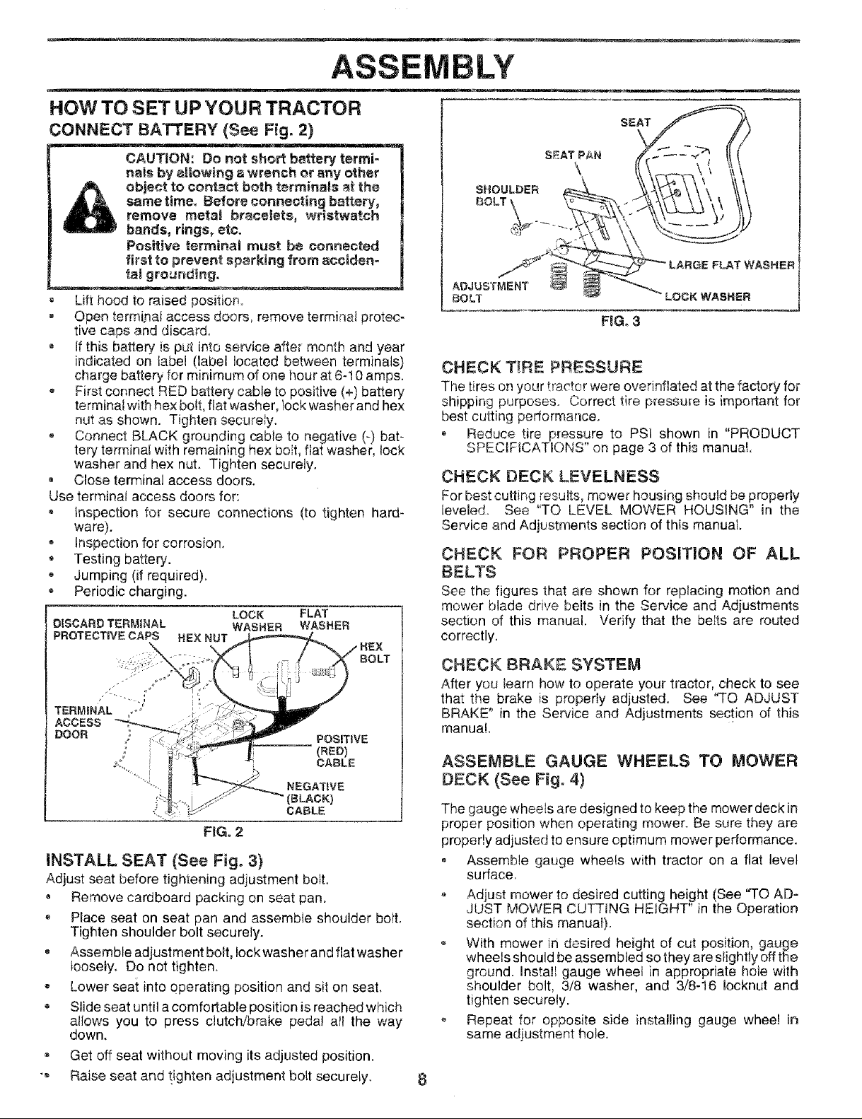
CONNECT BATTERY (See Fig. 2)
CAUTION: Do not short b_ttery termi-
nals by a|iowing awrench or any other
object to contact both terminals _ the
same time, Before connecting battery,
remove metal bracelets, wristwatch
bands, rings, etc.
Positive terminal must be connected
first to prevent sparking from acciden_
talgrognding,
Lifthood toraisedposition
- Open terrnif_ai access doors, remove terminal protec-
tive caps and discard.
If this battery is put dntoservice after month and year
indicated on label (label located between terminals)
charge battePj for minimum of one hour at 6-10 amps.
,, First connect RED battery cable to positive (+) battery
terminal with hex bolt, fiat washer, lock washer and hex
nut as shown. Tighten securely.
* Connect BLACK grounding cable to negative (-) bat-
tery terminal with remaining hex ooit, fiat washer, lock
washer and hex nut. Tighten securely.
Close terminal access doors.
Use terminal access doors for:
Inspection for secure connections (to tighten hard-
ware).
Inspection for corrosion.
Testing battery.
Jumping (if required).
Periodic charging.
LOCK FLAT
DISCARD TERMINAL WASHER WASHER
PROTECTIVE CAPS HEX NUT
SEAT
\
F_Go3
CHECK T!RE PRESSUAE
The tires on your tractor were overinftated at the factory, for
shipping purposes. Correct tire pressure is important for
best cutting performance.
, Reduce tire pressure to PSi shown in "PRODUCT
SPECIFICATIONS" on page 3 of this manual.
CHECK DECK LEVELNESS
For best cutting lesults, mower housing should be properly
leveled. See "TO LEVEL MOWER HOUSING" in the
Service and Adjustments section of this manual
CHECK FOR PROPER POSITION OF ALL
BELTS
See the figures that are shown for replacing motion and
mower blade drive belts in the Service and Adjustments
section of this manual. Verify that the belts are routed
correctly.
FIG. 2
INSTALL SEAT (See Fig. 3)
Adjust seat before tightening adjustment bott.
• Remove cardboard packing on seat pan.
Place seat on seat pan and assemble shoulder bolt.
Tighten shoulder bolt securely.
, Assemble adjustment bolt, Iockwasher and flat washer
tooseJy_ Do not tighten.
• Lower seat into operating position and sit on seat.
, Slide seat until a comfortable position is reached which
allows you to press clutch/brake pedal all the way
down.
Get off seat without moving its adjusted position.
"_ Raise seat and tighten adjustment bolt securely.
CHECK BRAKE SYSTEM
After you Iearn how to operate your tractor, check to see
that the brake is properly adjusted. See "TO ADJUST
BRAKE" in the Sewice and Adjustments section of this
manual.
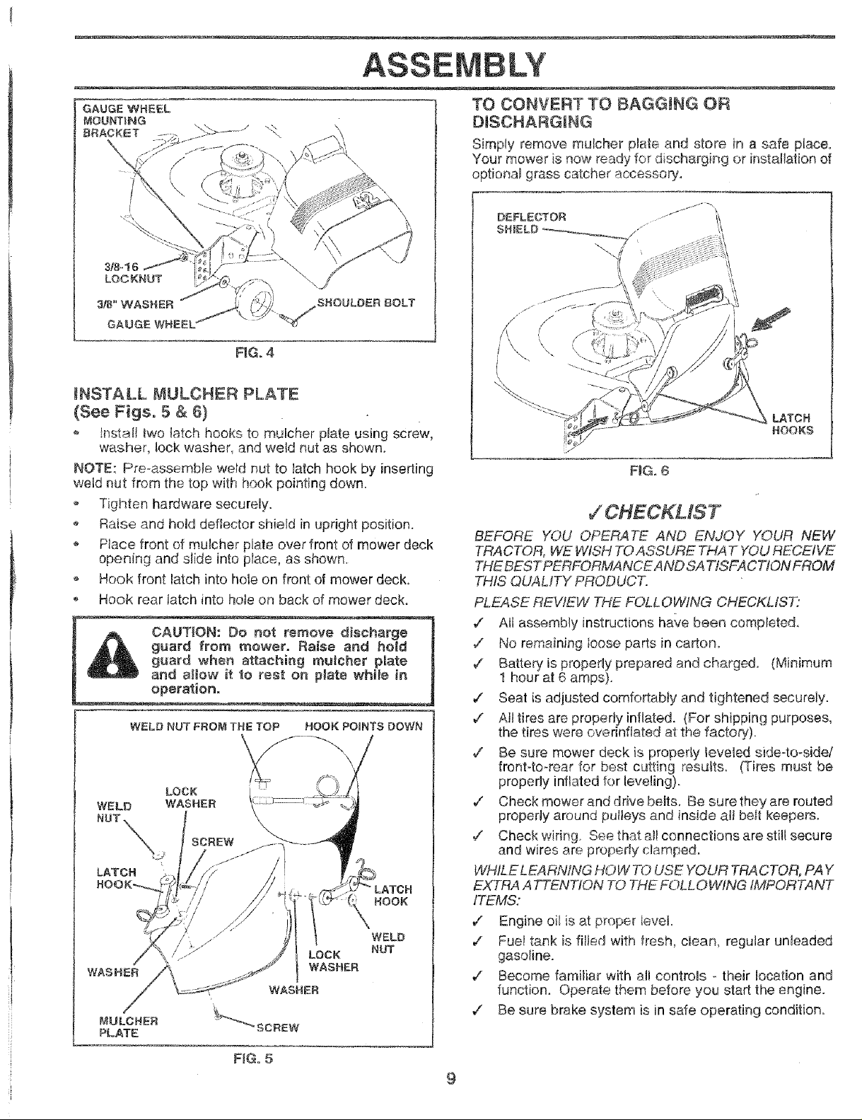
ASSEMBLE GAUGE WHEELS TO MOWER
DECK (See Fig. 4)
The gauge wheels are designed to keep the mower deck in
proper position when operating mower Be sure they are
proper!y adjusted to ensure optimum mower performance.
Assemble gauge wheels with tractor on a flat level
surface
,, Adjust mower to desired cutting height (See "TO AD-
JUST MOWER CUTTING HEIGHT" in the Operation
section of this manual)
With mower in desired height of cut position, gauge
wheels should be assembled so they are slightly offthe
ground, install gauge wheel in appropriate hole with
shoulder bolt, 3/8 washer, and 3/8-16 Iocknut and
tighten securely.
o Repeat for opposite side installing gauge whee! in
same adjustment hole.
Page 9
ASSE
GAUGE WHEEL
MOUNTING
BRACKET
318-! 6
LOOKNUT
3t8" WAS_-_ER
GAUGE WHEEL
\\
SHOULDER BOLT
FIG° 4
iNSTALL MULCHER PLATE
(See Figs° 5 & 6)
o !nstall two tatch hooks to mulcher plate using screw,
washer, lock washer, and weld nut as shown.
NOTE: Pre-assemble we_d nut to latch hook by inserting
weld nut from the top with hook pointing down.
o Tighten hardware securely.
,, Raise and held deflector shieid in upright position.
Place front of mulcher plate over front of mower deck
opening and slide into place, as shown.
o Hook front latch into hole on front of mower deck.
Hook rear latch into hole on back of mower deck.
guard from mower. Raise and hold
CAUTION: Do not remove discharge
guard when attaching muleher plate
and at_ow it to rest on plate while in
operation.
WELD NUT FROM THE TOP HOOK POINTS DOWN
\,
LATCH
HOOK
WASHER
TO CONVERT TO BAGGING OR
DISCHARGING
Simply remove mulcher plate and store in a safe place.
Your mower is now ready for discharging or installation of
optional grass catcher accessory.
DEFLECTOR
SH
FiG. 6
,/CHECKMST
BEFORE YOU OPERA TE AND ENJOY YOUR NEW
TRACTOR, WE WISH TOASSURE THAT Y'OURECEIVE
THE BEST PERFORMANCE AND SA77SFACTION FROM
THIS QUALITY PRODUCT.
PLEASE REVIEW THE FOLLOWING CHECKLIS7_"
¢" Atl assembly instructions have been completed.
,/ No remaining toose parts in carton.
¢ Battery is properly prepared and charged. (Minimum
1 hour at 6 amps)
,/ Seat is adjusted comfortabIy and tightened securely.
¢" At! tires are properly inflated. (For shipping purposes,
the tires were overinfiated at the factory)
/ Be sure mower deck is properly teveled side-to-side/
front-to-rear for best cutting results. (Tires must be
properly inflated for leveling).
v" Check mower and drive belts. Be sure they are routed
properly around pulteys and inside all belt keepers.
,/ Check wiring See that al! connections are still secure
and wires are properly ctamped_
WHfLE LEARNING HOW 7"0 USE YOUR TRACTOR, PAY
EXTRA ATTENTION TO THE FOLLOWING iMPORTANT
ITEMS:
v" Engine oil {sat proper levet.
,/ Fuel tank is filled with fresh, clean, regular unleaded
gasoline.
•/ Become familiar with all controls o their location and
function. Operate them before you start the engine.
7 Be sure brake system is in safe operating condition.
FiG. 5
Page 10
OPERATIO
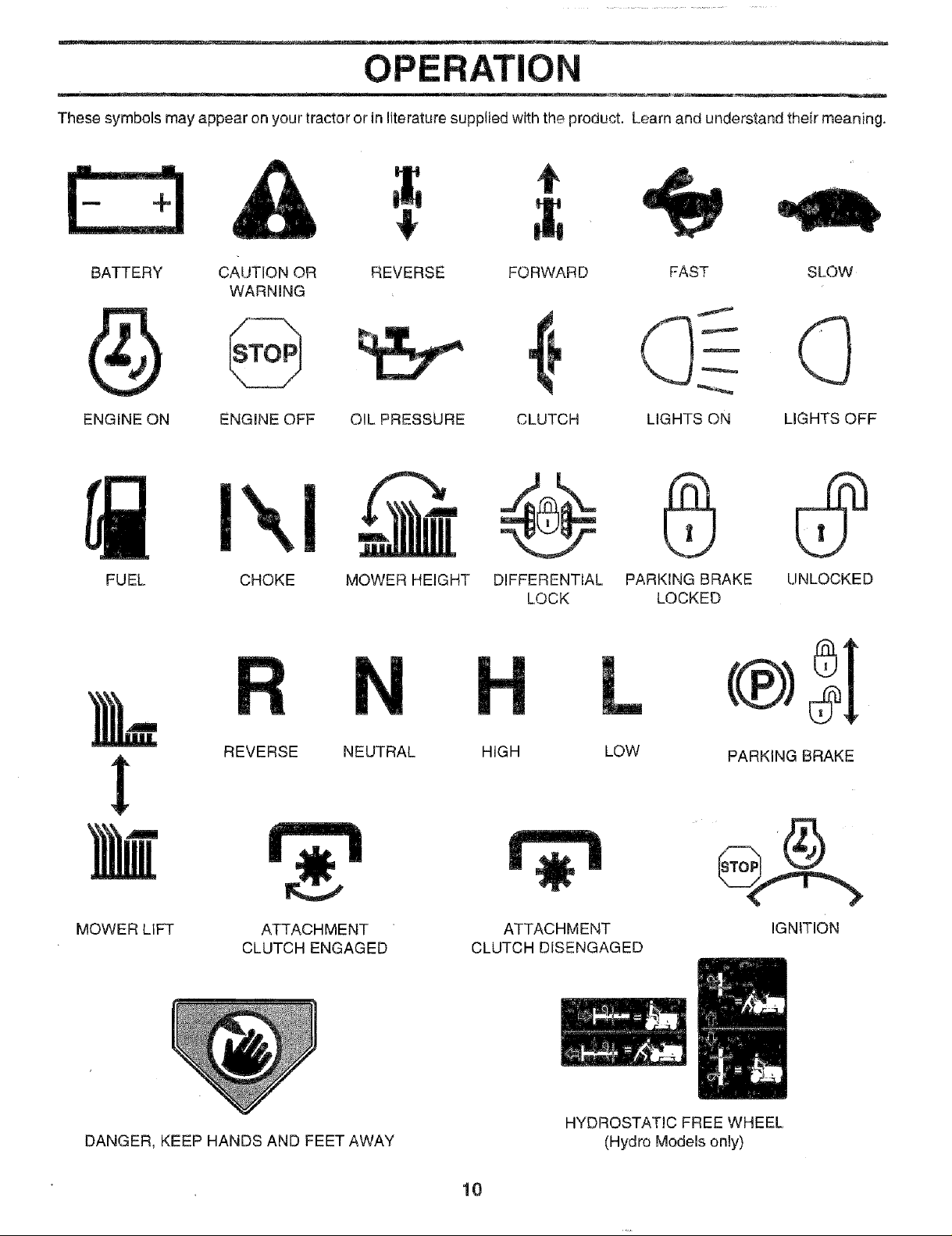
These symbols may appear on your tractor or in literature supplied with the product. Learn and understand their meaning.
t
E3
$
BATTERY
ENGINE ON
FUEL CHOKE MOWER HEIGHT DIFFERENTIAL
CAUTION OR FORWARD FAST SLOW
WARNING
ENGINE OFF OIL PRESSURE CLUTCH LIGHTS ON LIGHTS OFF
REVERSE
LOCK
PARKING BRAKE UNLOCKED
LOCKED
L
REVERSE NEUTRAL HIGH
MOWER LIFT ATTACHMENT
CLUTCH ENGAGED
DANGER, KEEP HANDS AND FEET AWAY
ATTACHMENT
CLUTCH DISENGAGED
HYDROSTATIC FREE WHEEL
10
LOW
(Hydro Models only)
PARKING BRAKE
IGNITION
Page 11
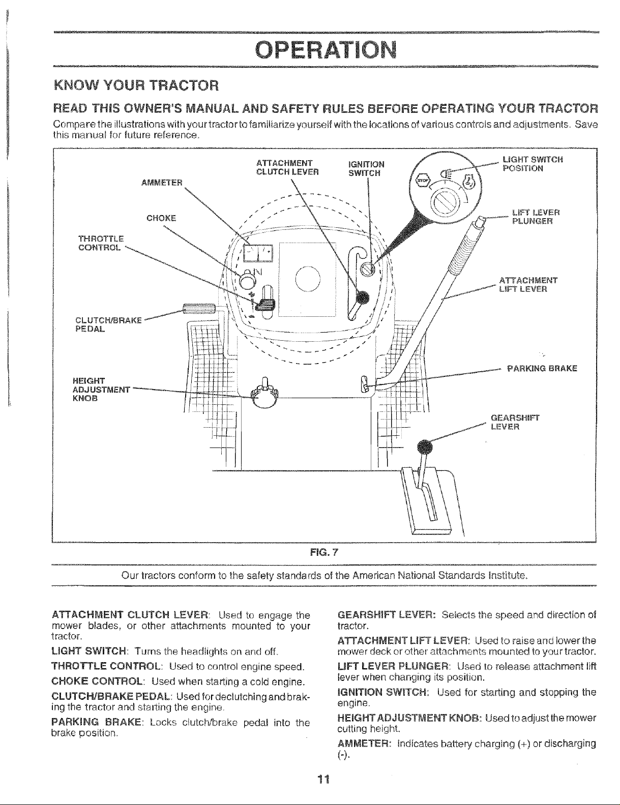
KNOW YOUR TRACTOR
READ THiS OWNER'S MANUAL AND SAFETY RULES BEFORE OPERATING YOUR TRACTOR
Compare the illustrations with your tractor to familiarize yourself with the locations of various controls and adjustments Save
this manual for future reference.
CLUTCH/BRAKE
PEDAL
HEEGHT
ADJUSTMENT
KNOB
ATTACHMENT IGNmON POS_T_ON
CLUTCH LEVER SWITCH
UGHT SW_TOH
l-
Our tractors conform to the safety standards of the American National Standards _nstitute.
ATTACHMENT CLUTCH LEVER: Used to engage the
mower blades, or other attachments mounted to your
tractor.
LIGHT SWITCH: Turns the headlights on and off
THROTTLE CONTROL: Used to control engine speed.
CHOKE CONTROL: Used when starting a cold engine.
CLUTORtBRAKE PEDAL: Used for declutching and brak-
ing the tractor and starting the engine.
PARKING BRAKE: Lacks clutch/brake pedal into the
brake position
FIG. 7
GEARSHIFT LEVER: Selects the speed and direction of
tractor.
ATTACR_.,_ENT LiFT LEVER: Used to raise and lower the
mower deck or other attachments mounted to your tractor.
L_Fr LEVER PLUNGER: Used to release attachment lift
lever when changing its position.
IGNRTDONSW_TCH: Used for starting and stopping the
engine.
HEmGHTADJUST[_ENT KNOB: Used to adjust the mower
cutting height,
AMMETER: Indicates battery charging (+) or discharging
(-).
11
Page 12
oreign obj_
__e. Always wear safety glass_te operating your J
_justments or repairs. We rec_._ion _afety mask
over th
HOW TO USE YOUR TRACTOR
! A__eav- I
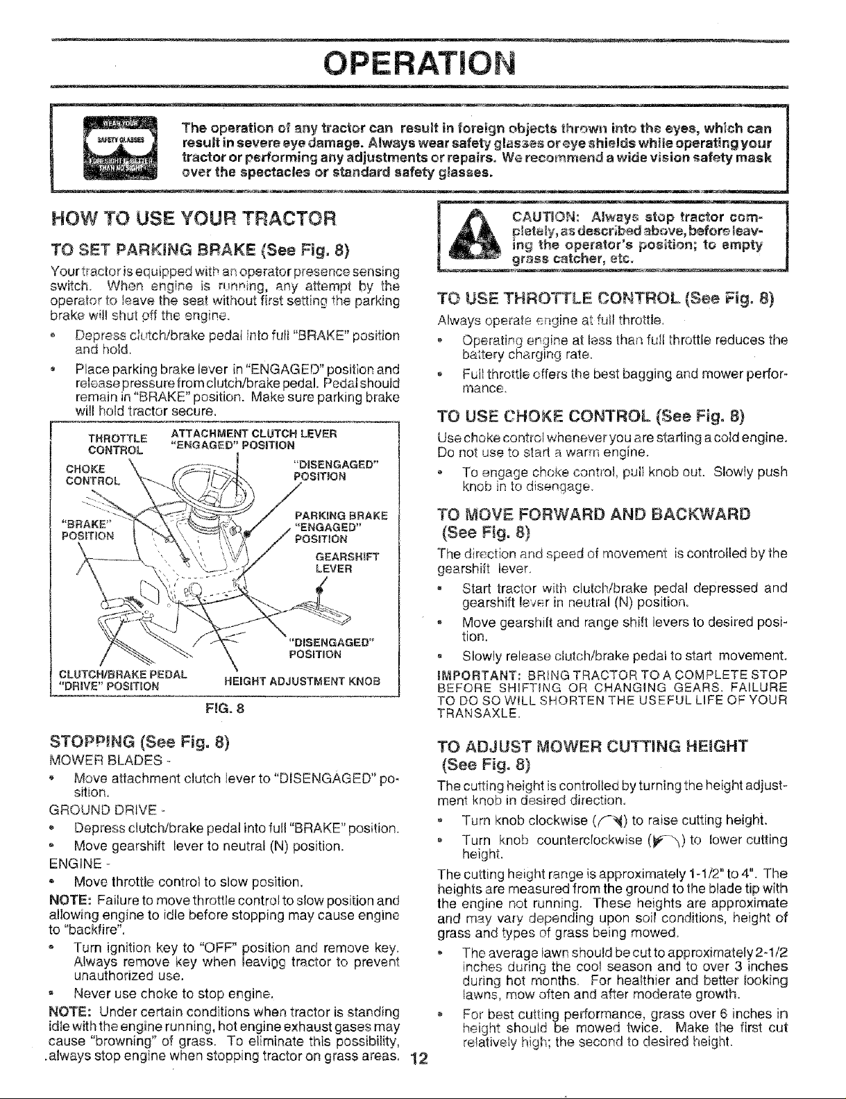
TO SET PARKING BRAKE {See Fig. 8)
Your tractor is equipped with an operator presence sensing
switch When engine is running, any attempt by the
operator to leave the seat without first setting the parking
brake will shut pff the engine°
Depress c_utch/brake pedat into full "BRAKE" position
and hold,
Place parking brake lever in "ENGAGED" position and
releasepressure from clutch/brake pedal. Pedal should
remain in"BRAKE" position. Make sure parking brake
will hold tractor secure,
THROTTLE
CONTROL
CHOKE
CONTROL
ATTACHMENT CLUTCH LEVER
"ENGAGED"POSITION
"DISENGAGED"
POSiTiON
! toempty I
TO USE THROTTLE CONTROL (See "-Fig,8)
Always operate engine at full throttle,
, Operating engine at less than full throttle reduces the
baltery charging rate.
, Full throttle offers the best bagging and mower perfor-
rnance.
TO USE CHOKE CONTROL (See Fig. 8)
Use choke control whenever you are starting acold engine.
Do not use to stad a warm engine.
• To engage choke control, pull knob out. Slowly push
knob in to disengage_
PARKtNG BRAKE
"ENGAGED"
POSITION
GEARSHIFT
LEVER
"DISENGAGED"
POSITION
CLUTCH/BRAKE PEDAL
"DR_VE" POSMON
HEIGHT ADJUSTMENT KNOB
FIG. 8
STOPPING (See Fig. 8)
MOWER BLADES -
Move attachment clutch lever to "DISENGAGED" po-
sition,
GROUND DRIVE -
Depress clutch/brake pedal into full "BRAKE" position.
o Move gearshift lever to neutral (N) position.
ENGINE -
® Move throttle control to slow position,
NOTE: Failure to move throttle control to slow position and
allowing engine to idle before stopping may cause engine
to "backfire".
- Turn ignition key to "OFF" position and remove key.
Always remove key when teaviog tractor to prevent
unauthorized use.
o Never use choke to stop engine.
NOTE: Under certain conditions when tractor is standing
idle with the engine run ning, hot engine exhaust gases may
cause "browning" of grass. To eliminate this possibility,
.always stop engine when stopping tractor on grass areas, 12
TO MOVE FORWARD AND BACKWARD
(See Fig. 8)
The dir_>ction and speed of movement is controlled by the
gearshift tever.
Start tractor with clutch/brake pedal depressed and
gearshift lever in neutral (N) position.
Move gearshift and range shift levers to desired posi-
tion.
, Slowly release clutch/brake pedal to start movement.
IMPORTANT: BRING TRACTOR TO A COMPLETE STOP
BEFORE SHIFTING OR CHANGING GEARS. FAILURE
TO DO SO W!LL SHORTEN THE USEFUL LIFE OF YOUR
TRANSAXLE.
TO ADJUST MOWER CU_ING HEIGHT
(See Fig. 8)
The cutting height is controlled by turning the height adjust-
ment knob in desired direction.
o Turn knob clockwise (#--_) to raise cutting height.
Turn knob counterclockwise (_-_,_)to tower cutting
heighL
The cutting height range is approximately 1-1/2" to 4". The
heights are measured from the ground to the blade tip wi[h
the engine not running. These heights are approximate
and rnay vary depending upon soil conditions, height of
grass and types of grass being mowed.
The average lawn should be cut to approximately 2-!/2
inches during the cool season and to over 3 inches
during hot months. For healthier and better tooking
lawns, mow often and after moderate growth,
For best cutt{ng performance, grass over 6 inches in
height should be mowed twice. Make the first cut
relatively high; the second to desired height.
Page 13
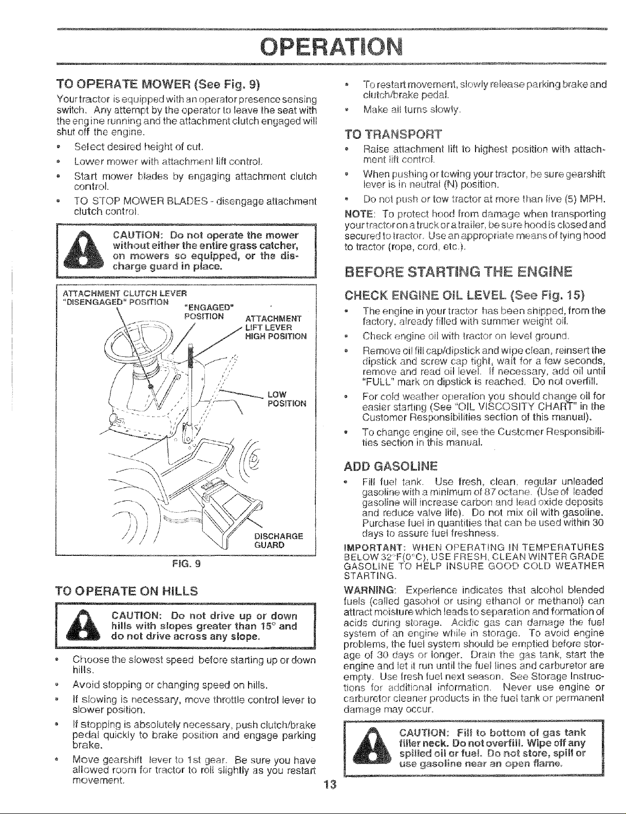
TO OPERATE MOWER (See Fig. 9}
Your tractor is equipped with an operator presence sensing
switch. Any attempt by the operator to leave the seat with
the eng ine running and the attachment clutch engaged will
shut off the engine.
o Select desired height of cut,
, Lower mower with attachmenf lift control.
Start mower bMades by engaging attachment clutch
control
. TO STOP MOWER BLADES --disengage attachment
clutch control_
witho_t either the entire grass catcher,
I!_ CAUTION: 13onot operate the mower
on mowers so equipped, or the dis-
charge guard in ptace.
To restart movement, slowly release parking brake and
ci_tch!brake pedal
, Make all lurns slowly,
TO TRANSPORT
• Raise attachment lift to highest position with attach_
ment iifl control
o When pushing or towhg yourtractor be sure gearshift
lever is it, neutral (IX!)position.
Do not push or tow tractor at more than five (5) MPH.
NOTE: To protect hood from damage when transporting
your tractoron a truck or a trailer, be s__Jre hoed is closed and
secured to tractor. Use an appropriate means of tying hood
to tractor {rope, cord. etc.)_
BEFORE STARTING THE ENGINE
CHECK EiNGINE OIL LEVEL (See Fig, 15)
. The engine in your tractor has been shipped, from the
factory already filled with surnmer weight oil
Check engine oil with tractor on ievel ground
o Remove oil fill cap/dipstick and wipe clean reinsert the
dipstick and screw cap tight, wait for a few seconds,
remove and read oH level If necessar!i, add oil until
"FULL" mark on dipstick is reached Do not ovediII.
For cold weather operatior_ yo_.sshould change oil for
easier starting (See "OIL VISCOSITY CHART" in the
Customer Responsibilities section of this manual)°
. To change engine oil, see the Customer Responsibili-
ties section in this manual.
FIG. 9
TO OPERATE ON HILLS
o Choose the slowest speed before starling up or down
hills.
. Avoid stopping or changing speed on hills.
if slowing is necessary, move throttle control lever to
slower position
If stopping is absolutely necessary, push clutch!brake
pedal quickly to brake position and engage parking
brake.
o Move gearshift lever to 1st gear. Be sure you have
allowed room for tractor to roit stightly as you restart
movement_
ADD GASOLINE
. Fill fuel tank. Use fresh, clean regular unleaded
gasoline with a m nimum of 87 octane_ (Use of leaded
gasoline will increase carbon and lead oxide deposits
and reduce valve life) Do not mix oil with gasoline.
Purchase fcJetin quantities that can be used within 30
days to assure fuel freshness.
IMPORTANT: WHEN OPERATING IN TEMPERATURES
BELOW32 F(0'_O),USE FRESH CLEAN WINTER GRADE
GASOLINE TO HELP INSURE GOOD COLD WEATHER
STARTING.
WARNING: Experience indicates that alcohol blended
fuels (caNed gasohol or using ethanol or methanol) can
attract moisture which leads to separation and formation of
acids during storage. Acidic gas can damage the fue!
system of an engine while in storage_ To avoid engine
problems, the fuel system should be emptied before stor-
age of 30 days or longer. Drain the gas tank, start the
engine and let it run until the fuet lines and carburetor are
empty. Use fresh fuel next season. See Storage Instruc-
tions for additional information Never use engine or
carburetor cleaner products in the fuet tank or permanent
damage may occur
1 t_ f_ll-Wipe°ffanY
_NII or
13
Page 14
OPERATION
TO START ENGINE (See Fig. 8)
When starting the engine for the first time or if the engine
has run out of rue!, it will t_._keextra cranking time to move
fuel from the tank to the engine.
Sit on seat in operating position, depress clutch/brake
pedal and set parking brake.
Place g_ar shift iever in neutral (N) position
, Move attachment clutch to "DISENGAGED" position.
Move throttie conbot to fast position
,, PulI choke con_,'rolout for a coid engine start attempt.
Fo_a w_m_ entitle sta_ attempt the choke controi may
not be needed.
Note: Before sta_ing, read the warm and coid star}sg
procedures beDw.
Insertke2 _n_o_gn_tlonandturnkeyc_ockwlseto ._TART
position and release key as soon ss engine starts. Do
noJ run star!or continuously for more than fifteen sec-
onds per minute. !f the engiPe does not start after
several attempts, push choke centre! in wait a few
minutes and try again, tfengine still does not start, pull
the choke control out and retry.
WARM WEATHER STARTING (500 F and above)
When engine starts, slowly push choke control in until
the engine begins to run smoothly. Ifthe engine starts
to run roughly, put! the choke controt ou_ slightly for a
few seconds and then continue to push the control in
slowly,
• The attachments and ground drive can now be used. If
the engine does not accept the load, restart the engine
and aJtowit Io warm up for one minute using the choke
as described above.
COLD WEATHER STARTING (50° F and below)
,, When engine sta_s, slowly push choke control in untit
the engine begins to run smoothly Continue to push
the choke control in small steps attowing the engine to
accept small changes in speed and load, untii the
choke control is fully in. _f the engine starts to run
roughly, pu!l the choke control out slightly for a few
seconds and then continue to push the control in
slowly. This may require, an engine warm-up period
from several seconds to several minutes, depending
on the temperature.
, The attachments can be used during the engine warm-
up period and may require the choke control be pulted
out _sfightly
NOTE: If at a high altitude (above 3000 feet) or in cold
temperatures (below 32 F) the carburetor fuel mixture may
need to be adjusted for'best engine performance. See "TO
ADJUST CARBURETOR" in the Service and Adjustments
section of this manuai.
MOWING TiPS
Tire chains cannot be used when the mower housing is
attached to tractor.
, Mower should be properly ieveled for best mowing
pedormance. See "TO LEVEl_ MOWER HOUSING" in
the Service and Adiustments section of this manuat.
', The left hand side of mower should be used for trim-
ming.
- Drive so that clippings are discharged onto the area
that has been cut. Have the cut area to the right of the
tractor. This wil! result in a mare even distribution of
clippings and more uniform cutting.
o When mowing large areas, start by turning to the right
so that clippings wilI discharge away from shrubs,
fences, driveways, etc. After one or two rounds, mow
in the opposite direction making left hand turns until
finished (See Fig. 10 }
If g_'ass;s extremeiy tall, it shouid be mow_d twice to
reduce iced and possib e fire hazard from dried clip-
pings. Ma',<efirs_ cut relat vety high; the secededto the
desir_ d height.
, Do not mow grass when it is wet. Wet grass will p_ug
mower a_d leave undesirable clu _nps A'!,-,_¢g_ass to
dr_ before mowing.
• Aw_ss operator engne at rut! th_oit!e when mowin.g to
ass_ re better n owing performs.rice m,.d proper dis-
charge of matafi_l. Regulate gruund speea by seiect-
ing e !o_ ennt_gh gear to give the mower cuthog
pedormanee as weti as the quality of cut aesired.
, When operating attachments, select a ground speed
that will suit the terrain and give best performance of
the attachment being used.
FIG,, 10
MULCHING MOWING TIPS
iMPORTANT FOR BEST PERFORMANCE, KEEP
MOWER HOUSING FREE OF BUILT-UP GRASS AND
TRASH. CLEAN AFTER EACH USE
o The special mulching blade will recut the grass clip-
pings many times and reduce them in size so that as
they fall or_o iha iawn they will disperse into the grass
and not be noticed. Also, tr_e mulched grass will
biodegrade quickty to provide nutrients for the lawn.
Always mu_c_ wth your highest engine (blade) speed
as this will provide the best recutting action of the
blades
Avoid cutting your lawn when it is wet. Wet grass tends
to form clumps and interferes with the mulching action.
The besttime to mow your lawn is the earty afternoon.
At this time _hegrass has dried and the newly cut area
will not be exposed to the direct sun.
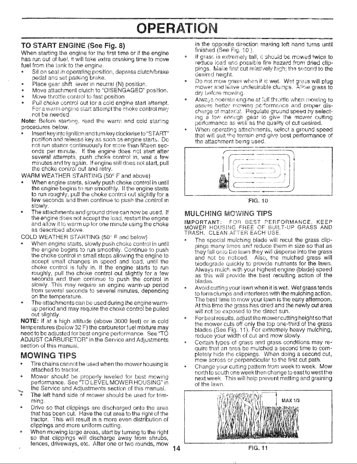
For best results, adjust the mower cuttihg height so that
the mower cuts off only the top one-third of the grass
blades (See Fig. 11). For extremely heaw mulching,
reduce your width of cut and mow slowly.
o Certain types of grass and grass conditions may re-
quire tha_ an area be mulched a second time to com-
pletely hide the clippings When doing a second cut,
mow across or perpendicular to the first cut path.
Change your cutting pattern from week to week. Mow
north to south one week then change to east to west the
next week. This will help prevent matting and graining
of the lawn.
14 NG° tl
Page 15
CUSTO RESPONSIBIUTI
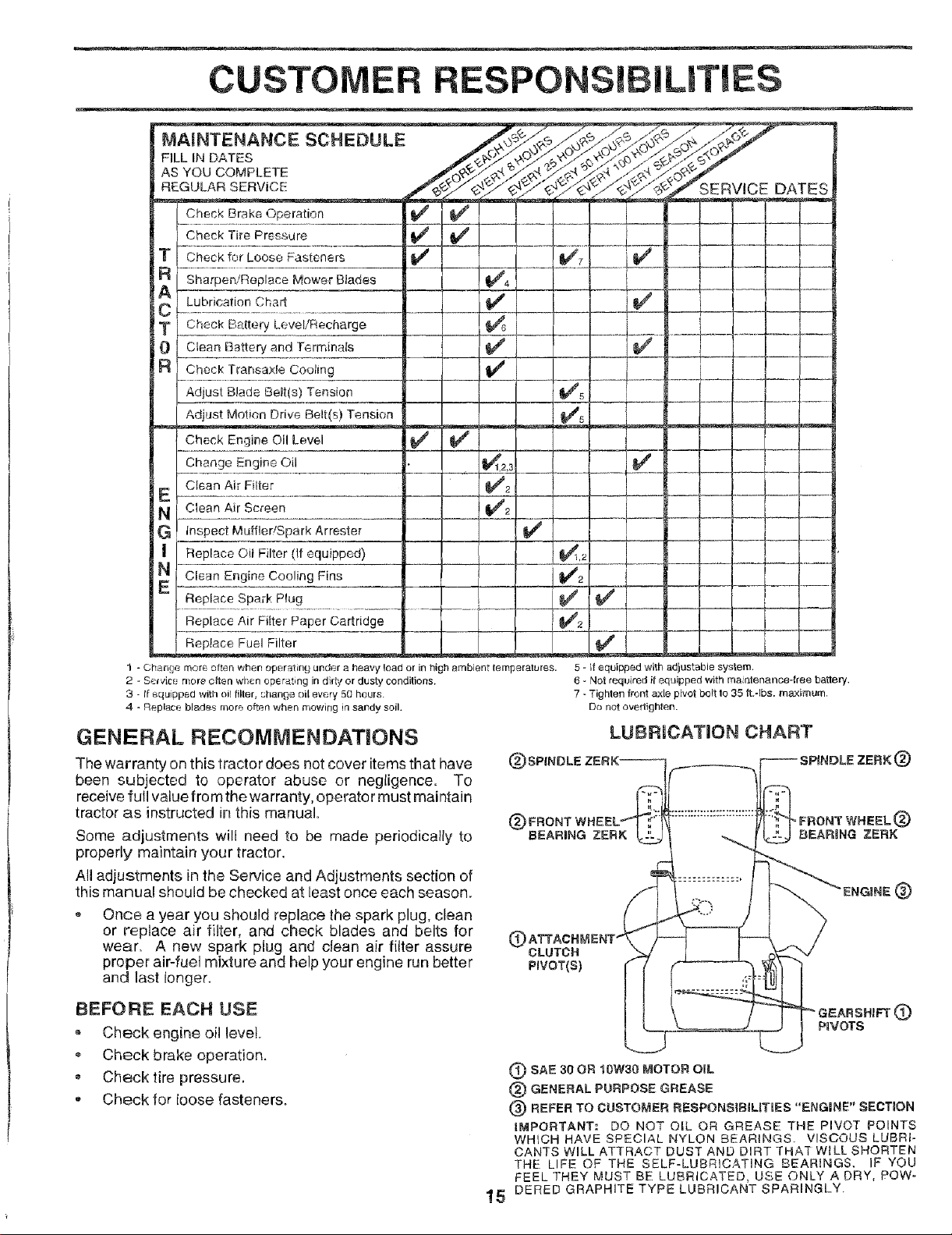
MAINTENANCE SCHEDULE
FiLL IN DATES
AS YOU COMPLETE
REGULAR SERVICE
Check Brake Operation
Check Tire Prc-ssure
Check for Loose Fasteners
Sharpen/Replace Mower Blades
Lubrication Chart
Check B£ttery Level/Recharge
Ctean Battery and Terminals
Check Transa×fe Cooling
Adjust Blade Belt(s) Tension
Adjust Motion Drive Belt(s) Tension
Engine Oil Level
Change Engine Oil
Clean Air Filter
Clean Air Screen
Inspect Muffler/Spark Arrestor
Replace 0il Filter (If equipped)
Clear] Engine Cooling Fins
Replace Spark Plug
Replace Air Fitter Paper Cartridge
Replace Fuel Filter
1 - Chan£e mere often when operating under a heavy load or in hi 1 ambient tern
2 Se_vice mere often when operating in didy or dusty conditions.
3 - tf equipped with oil filter, change oil every 50 hours.
4 - Replace blades more often when mowing in sandy soil.
GENERAL RECOMMENDATIONS
The warranty on this tractor does not cover items that have
been subjected to operator abuse or negligence. To
receive full value from the warranty, operator must maintain
tractor as instructed in this manual.
Some adjustments will need to be made periodically to
properly maintain your tractor.
All adjustments in the Service and Adjustments section of
this manual should be checked at least once each season,
- Once a year you should replace the spark plug, clean
or replace air filter, and check blades and belts for
wear_ A new spark plug and clean air filter assure
proper air-fuel mixture and help your engine run better
and last longer.
SERVICE DATES
>aratures.
5 - If equipped with adjustable system.
6 - Not required if equipped with mairllenance-free battery.
7 - Tighten front axle pivot belt to 35 ft.-Ibs, maximum.
Do not ovedighten.
LUBRICATION CHART
(_SPINDLE (_)
(_FRONT
BEARING ZERK
G
OLUTCR
PIVOT(S)
BEFORE EACH USE
. Check engine oil level
• Check brake operation.
Check tire pressure.
Check for loose fasteners.
P_VOTS
®
(_ SAE 30 OR 10W30 MOTOR OiL
(_ GENERAL PURPOSE GREASE
G) REFER TO CUSTOMER RESPONSIBlUTIES "ENG|NE" SECTION
IMPORTANT." DO NOT OIL OR GREASE THE PIVOT POINTS
WHICH HAVE SPECIAL NYLON BEARINGS. VISCOUS LUBRI-
CANTS WILL ATTRACT DUST AND DIRT THAT W_LL SHORTEN
THE LIFE OF THE SELF-LUBRICATING BEARINGS. IF YOU
FEEL THEY MUST BE LUBRICATED, USE ONLY A DRY, POW-
1_ DERED GRAPHITE TYPE LUBRICANT SPARINGLY.
Page 16
CUSTOMER RESPO ILmTIES
TRACTOR
Always ob_rve safety rules when performing any mainte-
nance.
BRAKE OPERATION
Iftractor requires n'tore than six (6) feet stopping distance
at high speed inhighest gear, then brake must be adjusted.
(See "TO ADJUST BRAKE" in the Service and Adjust-
ments section of this manual).
TIRES
, Maintain proper ai,_'pre_-sure in all tires (See "PROD°
UC[ SPECIFICATIQ,',!S" on page 3 of this manual),
Keep tires free of gasoiine oil, or insect control chemi-
cals which can harm rubber.
• Avoid stumps, stones, deep ruts, sharp objects and
other hazards that may cause tire damage.
NOTE: To seal tire punctures and prevent flat tires due to
slow leaks, tire sealant may be purchased from your local
parts dealer. Tire sealant also prevents tire dry rot and
corrosion.
BLADE CARE
For best results mower blades must be kept sharp. Re-
place bent or damaged blades.
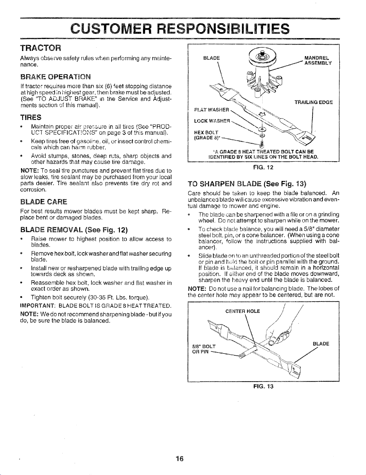
BLADE REMOVAL (See Fig. 12)
Raise mower to highest position to allow access to
blades.
, Remove hexbolt, lockwasherandflatwashersecuring
blade.
Install new or resharpened blade with trailing edge up
towards deck as shown.
. Reassemble hex bolt, lock washer and flat washer in
exact order as shown.
, Tighten bolt securely (30-35 Ft. Lbs. torque).
IMPORTANT: BLADE BOLT lS GRADE 8 HEATTREATED.
NOTE: We do not recommend sharpening blade- but ifyou
do, be sure the blade is balanced.
BLADE
TRAiLiNG EDGE
FLAT WASHER
HEXBOLT -.@
*A GRADE 8 HEAT TREATED BOLT CAN BE
IDENTIFIED BYSIXLINES ONTHEBOLTHEAD,
FiG, 12
TO SHARPEN BLADE (See Fig. 13)
Care should be taken [o keep the blade balanced. An
unbeiancea blade will cause excessive vibration and even-
tual damage to mower and engine.
° The blade can be sharpened with a file or on a grinding
wheel. Do not attempt to sharpen whi{e on the mower.
To check blade balance, you will need a 5/8" diameter
steel bolt, pin, or acone balancer. (When using a cone
ba]ancer, follow the instructions supplied with baF
ancer).
* Slide blade on _oan unthreaded portion of the steel bolt
or pin and i_,,:_Idthe bo{t or pin parallel with the ground.
if blade is b_Janced, it should remain in a horizontal
position. !t either end of the blade moves downward,
sharpen the heavy end until the blade is balanced.
NOTE: Do not use a nail for balancing blade. The lobes of
the center hole may appear to be centered, but are not°
/
CENTER ROLE
,//
16
518" BOLT
OR PIN
BLADE
FIG. 13
Page 17
CUSTO ILITIES
BATTERY
Your tractor has a battery charging system which is suffi-
cient for normal use. However, periodic charging of the
battery with an automotive charger will extend its life.
• Keep battery and terminals ciean.
• Keep battery bolts tight,
o Keep smafl vent holes open.
• Recharge at 6-10 amperes for 1 hour.
TO CLEAN BATTERY AND TERMINALS
Corrosion and did on the battery and terminals can cause
the battery to "leak" power.
® Remove terminal guard.
, Disconnect BLACK battery cable first then RED bat-
tery cable and remove battery from tractor.
= Rinse the battery with plain water and dry.
• Clean terminals and battery cable ends with wire brush
until bright.
, Coat terminals with grease or petroleum jeily.
, Reinstall battery (See "CONNECT BATTERY" in the
Assembly section of this manual).
V=BELTS
Check V-belts for deterioration and wear after !00 hours of
operation and replace if necessary. The belts are not
adjustable. Replace belts if they begin to slip from wear.
TRANSAXLE COOLING
Keep transaxle free from build-up of dirt and chaff which
can restrict cooling.
ENGINE
LUBR!CATION
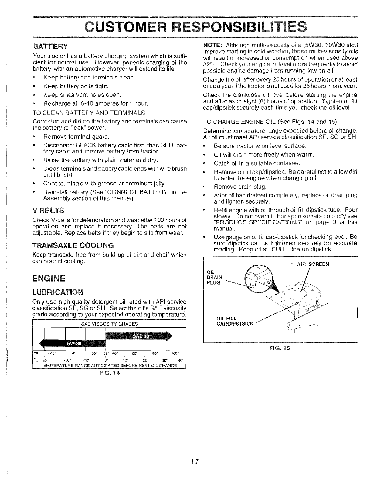
Only use high quality detergent oil rated with API service
classification SF, SG or SH. Select the oil's SAE viscosity
grade according to your expected operating temperature.
SAE VISCOSITY GRADES
NOTE: Although multi-viscosity oils (5W30, 10W30 etc.)
improve starting in cold weather, these multi-viscosity oils
will result in increased oil consumption when used above
32_'F. Check your engine oil level more frequently to avoid
possible engine damage from running low on oil.
Change the oil after every 25 hours of operation or at least
once a year ifthe tractor is not used for 25 hours in one year.
Check the crankcase oil level before starting the engine
and after each eight (8) hours of operation. Tighten oil fill
cap/dipstick securely each time you check the oi! levet.
TO CHANGE ENGINE OIL (See Figs. 14 and 15)
Determine temperature range expected before oil change.
All oil must meet APt service classification SF, SG or SH.
, Be sure tractor is on level surface.
• Oil will drain more freely when warm.
- Catch oil in a suitable container.
, Remove oi! fill cap/dipstick. Be careful not to allow dirt
to enter the engine when changing oil.
Remove drain plugo
After oil has drained completely, replace oil drain plug
and tighten securely.
o Refill engine with oil through oi! fitl dipstick tube. Pour
slowly. Do not overfill. For approximate capacity see
"PRODUCT SPECIFICATIONS" on page 3 of this
manual.
• Use gauge on oil fill cap/dipstick for checking level. Be
sure dipstick cap is tightened securely for accurate
reading. Keep oil at "FULL" line on dipstick.
OIL
DRAIN
PLUG
OIL FILL
CAP/DIPSTSICK
:C -30_ _20° -10 ° 0° 10 ° 20 ° 30 ° 40 °
TEMPERATURE RANGE ANTICIPATED BEFORE NEXT OIL CHANGE
RG. 14
FiG. 15
17
Page 18

CUSTOMER RESPONSIBILITIES
AIR FILTER (See Fig. 16)
Your engine wil] not mn _roper_y using a dirty air fiker.
Clean the foam pre-cleaner after every 25 hours of opera°
tion or every season, Sewice paper cad.ridge every 100
hours of operation or every season, whichever occurs first.
Service air cleaner more often under dusty conditions.
• Remove knob(s) and cover,
TO SERVICE PRE-CLEANER
, Slide foam pre-clear_er off cartridge,
Wash it in Tiquiddeterg)n_ and water.
, Squeeze it dry in a ciean cloth
, Saturate it in engine oil. Wrap it in clean, absorbent
cloth and squeeze to remove excess oil.
• If verj dirty or damaged, replace pre-cleaner.
o Reinstall pre-cleaner over cartridge.
, Reinstall cover and secure with knob(s).
TO SERVICE CARTRIDGE
, Remove wing nuts and cartridge plate.
, Carefully remove cartridge to prevent debris from en-
tering carburetor.
Clean cartridge by tapping gently on flat surface, tfvery
dirty or damaged, replace cartr dge
• Reinstall cartridge plate, wing nuts, precleaner, cover
and secure with knob(s).
IMPORTANT: PETROLEUM SOLVENTS, SUCH AS
KEROSENE, ARE NOT TO BE USED TO CLEAN THE
CARTRIDGE. THEY MAY CAUSE DETERiORATiON OF
THE CARTRIDGE. DO NOT OIL. CARTRIDGE, DO NOT
USE PRESSURIZED AIR TO CLEAN OR DRY
CARTRIDGE,
CLEAN AIR SCREEN (See Fig. 17)
Air screen must be kept free of dirt and chaff to prevent
engine damage from overhoating. Clean with awire brush
or compressed air to remove dirt and stubborn dried gum
fibers.
ENGINE COOLING FINS (See Fig. i7)
Remove any dust, dirt or oil from engine cooling fins to
prevent engine damage from overheating. Air guide covers
must be removed. Remove side panels and hood (See "TO
REMOVE HOOD AND GRILL ASSEMBLY" in the Service
and Adjustments section of this manual).
AIR GUIDE COVER (BOTH SIDES)
WING NUT
FOAM
PRE-CLEANER
AiR SCREEN
FIG. 17
CARTRIDGE
<__ PLATE
3ARTRIDGE
FKG.16
18
Page 19

CUSTOMER RESPO ILITIES
MUFFLER
inspect and replace corroded muffler and spark arrester (if
equipped) as it could create a fire hazard and/or damage.
CLAMP
SPAR K PLUGS
Replace spark plugs at the beginning of each mowing
season or after eveR' 100 hours of operation, whichever
occurs first. Spark plug type and gap setting are shown in
"PRODUCT SPECIFICATIONS" on page 3 of this manual.
IN-LIME FUEL FILTER (See Fig, 18)
The fuel filter should be replaced once each season. Iffuel
filter becomes ctogged, obstructing fuel flow to carburetor,
replacement is required.
= With engine coo!, remove filter and plug fuel line
sections.
, Place new fue! filter in position in fuel line with arrow
pointing towards carburetor.
° Be sure there are no fuel line leaks and clamps are
properly positioned.
, Immediately wipe up any spilled gasoline.
'!
F
FILTER _ --
NG. 18
CLEANING
o Clean engine, battery, seat, finish, etc. of all foreign
matter.
• Keep finished surfaces and wheels free of all gasoline,
oil, etc.
Protect painted surfaces with automotive type wax.
We do not recommend using a garden hose to clean your
tractor unless the electrical system, muffler, air filter and
carburetor are covered to keep water out. Water in engine
can result in a shortened engine life.
19
Page 20

_-- _ ii i = i,,i, ii !,,m. i= - --
SERVICE AND ADJUSTMENTS
CAUTION: BEFORE PERFORMING ANY SERVICE OR ADJUSTMENTS:
_ Depress cButcbJbrake pedal fully and set parking brake.
= Place gearshift lever in neutral (N) position.
, Place attachment clutch in "DISENGAGED" position.
Turn ignition key "OFF" and remove key.
, Make sure the blades and all moving parts have compiete!y stepped.
, Disconnect spark plu9 wire from spark plug and place wire where it cannot come in contact with
plug.
TRACTOR
TO REMOVE MOWER (See Fig. 19)
Mower will be easier to remove from the right side oftractor.
Place at_achrnent clutch in "DISENGAGED" position.
- Move attachment liftlever forward to {ower mower to its
lowest position.
* Rolr belt off engine pulley.
, Disconnect clutch rod from clutch lever by removing
retainer spring.
, Disconnect anti-sway bar from chassis bracket by
removing retainer spring.
, Disconnect suspension arms from rear deck brackets
by removing retainer springs.
o Disconnect front links from deck by removing retainer
springs,
, Raise lift lever to raise suspension arms. Slide mower
out from under tractor.
IMPORTANT: IF AN ATTACHMENT OTHER THAN THE
MOWER IS TO BE MOUNTED TO THE TRACTOR,
REMOVE THE FRONT LINKS,
TO INSTALL MOWER {See Fig= 19)
Raise attachment lift lever to its highest position.
• Slide mower under tractor with discharge guard to right
side of tractor.
Lower lift lever to its lowest position,
install mower in reverse order of removal instructions.
SUSPENS!ON
RETAINER
SPRING
ANTI=SWAY BAR
- _ o_
LEVER
CLUTCH
RETAINER
SPRING
PULLEY
1
RETAINER
SPRINGS
(BOTH SIDES)
FIG. 19
20
Page 21

SERVICE AN ADJU ENTS
TO LEVEL MOWER HOUSING
Adjust the mower while tractor is parked on level ground or
driveway. Make sure tires are properly inflated (See
"PRODUCT SPECIFICATIONS" on page 3 ofthis manual).
Iffires are over or undednftated, you will not properly adjust
your mower.
SIDE-TO-SIDE ADJUSTMENT (See Figs. 20 and 21)
* Raise mower to its highest position.
- At the midpoint of both sides of mower, measure height
from bottom edge of mowerto ground. Distance "A" on
both sides of mower should be the same or within 1/4"
of each other.
o If adjustment is necessary, make adjustment on one
side of mower only.
• To raise one side of mower, tighten lift link adjustment
nut on that side.
• To lower one side of mower, loosen lift link adjustment
nut on that side.
NOTE: E_achfull turn of adjustment nut will change mower
height about 1/8".
Recheck measurements after adjusting.
BOTTOM EDGE BOTTOM EDGE
OF MOWER TO OF MOWER TO
GROUND GROUND
FRONT-TO-BACK ADJUSTMENT (See Figs. 22 and 23)
LMPORTANT: DECK MUST BE LEVEL SIDE-TO-SIDE. IF
THE FOLLOWING FRONT-TO-BACK ADJUSTMENT IS
NECESSARY, BE SURE TO ADJUSTBOTH FRONT LINKS
EQUALLY SO MOWER WILL STAY LEVEL SIDE-TO-
SIDE,
To obtain the best cutting results, the mower housing
should be adjusted so that the front is approximately 1/8" to
1/2" lower than the rear when the mower is in its highest
position.
Check adjustment on right side of tractor. Measure dis-
tance "D" direclly in front and behind the mandrel at bottom
edge of mower housing as shown.
Before making any necessary adjustments, check that
both front links are equal in length. Both links should be
approximately 10-3/8".
• If links are not equal in length, adjust one link to same
length as other tink.
• To lower front of mower loosen nut "E" on both front
links an equal number of turns.
• When distance "D" is 1/8" to 1/2" lower at front than
rear, tighten nuts "F" against trunnion on both front
links.
, To raise front of mower, loosen nut "F" from trunnion on
both front links. Tighten nul "E" on both front links an
equal number of turns.
, When distance "D" is 1/[_" to 1/2" lower at front than
rear, tighten nut"F"against trunnion on both front links.
Recheck side4o-side adiustment..
F_G. 20
_\ SUSPENSION
\ ARM
FIG. 21
LiFT LINK
ADJUSTMENT NUT
NUT
21
FRONT LINKS TRUNNION
FiG. 23
I
E
Page 22

SERVICE AND ADJUSTMENTS
TO REPLACE MOWER BLADE DRIVE BELT
(See Fig. 24)
The mower blade drive belt may be replaced without tools.
Park the tractor on level surface. Engege parking brake.
BELT REMOVAL -
° Remove mower from tractor (See "TO REMOVE
MOWER" in this section of this manual).
• Work belt off b3th mandrel pulleys arid idler pulleys.
• Pull belt away from mower.
BELT INSTALLATION -
Install new belt in reverse order of removal.
, Make sure belt is in all pulley grooves and inside all belt
guides
, Install mower in reverse order of removal instructions.
MANDREL IDLER
PULLEY PULLEYS
MANDREL
PULLEY
FIG. 24
WITH PARKING BRAKE "ENGAGED"
NUT "A""
JAM NUT
OPERATING ARM
FIGo 25
TO REPLACE MOTION DRIVE BELT
(See Fig. 28)
Park the tractor on leve! surface. Engage parking brake.
For assistance, there is a belt installation guide decal on
bottom side of left footrest.
- Remove mower (See "TO REMOVE MOWER" in this
section of this manual.)
= Remove upper belt keeper,
Remove belt from stationary idler and clutching idler.
Pull belt slack toward rear of tractor. Remove belt
upwards from transaxle pulley by deflecting belt keep-
ers.
, Pull belt toward front of tractor and remove downwards
from around engine pulley.
• Install new belt by reversing above procedure.
IMPORTANT: MAKE SURE UPPER BELT KEEPER IS
POSITIONED PROPERLY BETWEEN LOCATOR TAB.
TO ADJUST BRAKE (See Fig. 25)
Your tractor is equipped with an adjustable brake system
which is mounted on the right side of the transaxle.
If tractor requires more than six (6) feet stopping distance
at high speed inhighest gear, then brake must be adjusted.
- Depress clutch/brake pedal and engage parking brake.
= Measure distance between brake operating arm and
nut "A" on brake rod.
If distance is other than 1-1/2", loosen jam nut and turn
nut "A" until distance becomes 1-1/2". Retighten jam
nut against nut "A".
Road test tractor for proper stopping distance as stated
above. Readjust if necessary. If stopping distance is
still greater than six (6) feet in highest gear, further
maintenance is necessary. Contact your nearest au-
thorized service center/department.
22
PULLEY
CLUTCHNG
iDLER
iDLER
PULLEY
TABS
_UPPER BELT
KEEPER
FiG. 26
Page 23

SERVICE AND ADJUSTMENTS
TRANSAXLE SHIFTER LINKAGE AND AD-
JUSTMENT (See Figs. 27 and 28)
The transaxle should be in neutral when the gear shift lever
is in the neutral (N) (lock gate) position. The adjustment is
preset at the factory; however, if adjustment is needed,
proceed as tollows:
• Make sure transaxle is in neutral (N).
Loosen two Iocknuts on tie rod.
Turn center rod until gearshift lever falls into neutral
lock gate on fender console.
Tighten Iocknuts securely.
LEVER
LOCK GATE
FiG, 27
LOCKNUTS
TO REMOVE WHEEL FOR REPAIRS
(See Fig, 29)
. Block up e.xla securely.
, Remove axle cover, retaining ring and washersto allow
wheel removaI (rear wheel contains a square key oDo
not lose).
• Repair tire and reassembleo
, OR rear wheels only: align grooves in rear wheel hub
and axle. Insert square key.
Replace washers and snap retaining ring securely in
axle groove.
Replace axle cover.
NOTE: To seal tire punctures and prevent flat tires due to
slow leaks, tire sealant may be purchased from your local
parts dealer. Tire sealant also prevents tire dry rot and
corrosion.
WASHERS
CENTER ROD
TRANSAXLE
FIG. 28
TO ADJUST STEERING WHEEL ALIGNMENT
If steering wheel crossbars are not horizontal (left to right)
whenwheels are positioned straight forward, remove steer-
ingwheel and reassemble per instructions inthe Assembly
section of this manual.
FRONT WHEEL TOE-IN/CAMBER
The front wheel toe-in and camber are not adjustable on
your tractor° if damage has occurred to affect the front
wheel toe-in or camber, contact your nearest authorized
service center/department.
AXLE COVER
SQUARE KEY <REAR
WHEEL ONLY)
FIG. 29
TO START ENGINE W_TH A WEAK BATTERY
'See Fig. 30}
CAUTION: Lead-acid batteries gener-
and smoking materials away from bat-
ateexptesivegases. Keepsparks, flame
teries. Always wear eye protection
when around batteries.
If your battery is too weak to start the engine, it should be
recharged. If "jumper cables",are used for emergency
starting, follow this procedure:
IMPORTANT: YOUR TRACTOR iS EQUIPPED WITH A 12
VOLT NEGATIVE GROUNDED SYSTEM. THE OTHER
VEHICLE MUST ALSO BE A 12 VOLT NEGATIVE
GROUNDED SYSTEM. DO NOT USE YOUR TRACTOR
BATTERY TO START OTHER VEHICLES.
TO ATTACH JUMPER CABLES o
• Connect each end of the RED cable to the POSiTiVE
(+) terminal of each battery, taking care not to short
against chassis.
Connect one end of the BLACK cable to the NEGA-
TIVE (-) terminal of fully charged battery.
o
Connect the other end of the BLACK cable to good
CHASSIS GROUND, away from fuei tank and battery.
TO
REMOVE CABLES, REVERSE ORDER -
BLACK cable first from chassis and then from the fully
charged battery.
23"
RED cable last from both batteries.
Page 24

VICE ADJUSTMENTS
FiG. 30
TO REPLACE HEADLIGHT BULB
• Raise hood.
• Pull bulb holder out of the hole in the backside of the
grill.
, Replace bulb il! holder and push bulb holder securely
back intothe hole tnthe backside of the grill.
, Close hood.
iNTERLOCKS AND RELAYS
Loose or damaged wiring may cause your tractor to run
poorly, stop running, or prevent it from starting.
• Check wiring. See electrical wiring diagram in the
Repair Parts section of this manual.
ENGINE
TO ADJUST THROTTLE CONTROL CABLE
(See Fig. 32)
The throttte controt has been _resat at the factory and
adjustment should not be necessary. Check adjustment as
described be!ow before loosening cable. If adjustment is
necessa_', proceed as follows:
With ei_g!r_eno_running, move fllrottle centre! !ever to
fast position.
, Check that swivel is against side of quarter circle. If it
is not, loosen cab!e clamp screw and pull caD/e back
until swivel is against quarter circle. Tighten cable
clamp screw securely.
TO ADJUST CHOKE CONTROL (See Fig. 33)
The cl_oke control has been preset at the factory and
adjustment should not be necessary', Chock adjustment as
described below before loosening cab!e, if adjustment is
necessary,, proceed as follows:
• With engine not running, move choke control (located
on dash panel) to full choke position.
• Remove air cleaner cover, filter and cartridge plate to
expose carburetor choke (see "AIR FILTER" in the
Customer Responsibilities section of this manual).
• Choke should be closed. If it is not, loosen casing
ciamp screw and move choke cable until choke is
completely closed. Tighten casing clamp screw se-
curely.
Reassemble air cleaner.
CLAMP SCREW __
TO REPLACE FUSE
Replace with 30 amp automotive-type plug-in fuse. The
fuse holder is located behind the dash.
TO REMOVE HOOD AND GRILL ASSEMBLY
(See Fig. 31)
• Raise hood.
• Unsnap headlight wire connector.
, Stand infront of tractor. Grasp hood at sides, tilt toward
engine and lift off of tractor.
• To replace, reverse above procedures.
HOOD
\
\
\- /
, }
FiG. 31 24
HEADLIGHT
WIRE
CONNECTOR
QUARTER
CIRCLE
SWIVEL
FIG. 32
I '
CASING / :_J_'_.q__ /
CLAMP _ --,
scREw ,
FIG. 33
Page 25

SERVICE AN ADJUSTMENTS
TO ADJUST CARBURETOR (See Figs. 34 &
35)
The carburetor has been preset at the factory and adjust-
ment should not be necessary. However, minor adjust-
ment may be required to compensate for differences in fuel,
temperature, altitude or [cad. If the carburetor does need
adjustment, proceed as follows:
In general, turning the mixture screw in (clockwise) de-
creases the supply offuel to the engine giving aleaner fuel/
air mixture. Turning the mixture screw out (counterclock-
wise) increases the supply of fuel to the engine giving a
richer fuel!air mixture
IMPORTANT: DAMAGE TO THE NEEDLES AND THE
SEATS IN CARBURETOR MAY RESULT IF SCREW IS
TURNED IN TOO TIGHT.
PRELIIVHNARY SETTING -
• Be sure you have a clean air filter, and the throttle
controt cable and choke are adjusted properly (see
above).
® With engine off turn idle mixture screw in (clockwise)
closing itfinger tight and then turn out (counterclock-
wise) 1-4/4 to 1-1/2 turns.
FINAL SETTING -
Start engine and allow to warm for five minutes. Make
final adjustments with engine running and shift/motion
control lever in neutral (N) position.
- With throttle control lever in slow position, hold throttle
lever against idle speed screw and adjust idle speed
screw to obtain !200 to 1400 RPM.
o While still holding throttle lever against idle speed
screw, turn idle mixture screw in (clockwise) until
engine begins to die and then turn out (counterclock-
wise) until engine runs rough. Turn screw to a paint
midway between those two positions.
= Continue to hold throttle lever against idle speed screw
and adjust idle speed screw to obtain 900 to 1200 RPM.
Release throttle lever.
ACCELERATION TEST -
Move throttle control lever from slow to fast position. If
engine hesitates or dies, turn idle mixture screw out
(counterclockwise) 1/8 turn. Repeat test and continue
to adjust, if necessary, until engine accelerates
smoothly.
High speed stop is factory adjusted. Do not adjust -
damage may result.
tI_PORTANT: NEVER TAMPER W_TH THE ENGINE
GOVERNOR, WHICH IS FACTORY SET FOR PROPER
ENGINE SPEED. OVERSPEEDING-THE ENGINEABOVE
THE FACTORY HIGH SPEED SETTING CAN BE
DANGEROUS. IF YOU THtNKTHE ENGiNE-GOVERNED
HIGH SPEED NEEDS ADJUSTING, CONTACT YOUR
NEAREST AUTHORIZED SERVICE CENTER/
DEPARTMENT WHICH HAS PROPER EQUIPMENT AND
EXPERIENCE TO MAKE ANY NECESSARY
ADJUSTMENTS.
_DLE SPEED
SCREW
IDLE M_XTURE
SCREW
THROTTLE
LEVER
FIG. 34
IDLE SPEED (_-_
LEVER
mDLE M_XTURE
SCREW
F_Go35
25
Page 26

STORAGE
Immediately prepare your tractor for storage at the end of
the season or if the tractor wil{ not be used for 30 days or
more,
,_ ,L _ inside a building
_ w_achan openfRame
_ or spark_ engine to cool
TRACTOR
Remove mower from tractor for winter storage. When
mower is to be stored for a period of time, clean it thor-
oughly, remove all dirt, grease, leaves, etc. Store in a
clean, dry area.
= Clean entire tractor (See"CLEANING" inthe Customer
Responsibilities section of this manual).
, inspect and replace belts, if necessary (See belt re-
placement instructions in the Service and Adjustments
section of this manual).
* Lubricate as shown in the Customer Responsibilities
section of this manual.
, Be sure that all nuts, bolts and screws are securely
fastened. Inspect moving parts for damage, breakage
and wear. Replace if necessary.
• Touch up all rusted or chipped paint surfaces; sand
lightly before painting.
BATTERY
= Fully charge the battery for storage.
• After a period of time in storage, battery may require
recharging.
® To help prevent corrosion and power leakage during
long periods of storage, battery cables should be
disconnected and batter/cleaned thoroughly (see "TO
CLEAN BATTERY AND TERMINALS" in the Cus-
tomer Responsibilities section of this manual).
After cleaning, leave cables disconnected and place
cables where they cannot come in contact with battery
terminals.
Be sure battery drain tube is securely attached.
, If battery is removed from tractor for storage, do not
store battery directly on concrete or damp surfaces.
ENGINE
FUEL SYSTEM
LMPORTANT: IT IS iMPORTANT TO PREVENT GUM
DEPOSITS FROM FORMING IN ESSENTIAL FbEL
SYSTFM PARTS SUCH AS CARBURETOR, FUEL F{LTER,
FUEL HOSE, OR TANK DURING STORAGE. ALSO,
EX!_ERIENCE ;NDICATES CHAT ALCOHOL BLENDED
FUELS (CALLED GASOHOL OR USING ETHANOL OR
METHANOL) CAN ATTRACT MOISTURE WHICH LEADS
TO SEPARATION AND FORMATION OF ACIDS DURING
STORAGE, ACIDIC GAS CAN DAMAGE THE FUEL
SYSTEM OF AN ENGINE WHILE IN STORAGE.
, Drain the fuel tank.
• Start the enoine and let it run until the fue! lines and
carburetor are empty.
Never use engine orcarbur_tor cleaner products in the
fuji tank or permanent damage may occur.
® Use fresh fuel next season.
NOTE: Fuel stabilizer is an acceptable aiternat,ve in
mlntm_z_ngthe formation of fuel gum deposits during stor-
age, Add stabilizer to gasoline in fue! tank or storage
container. Always follow the mix ratio found on stabilizer
container. Run engine at least 10 minutes after adding
stabilizer to allow the stabilizer to reach the carburetor, Do
notdrain the gas tank and carburetor if using fuel stabilizer.
ENGmNE OiL
Drain oil (with engine warm) and replace with clean engine
oil, (Sea "ENGINE" in the Customer Responsibilities
section of this manual).
CYUNDERS
Remove spark plug(s).
Pour one ounce of oil through spark plug hole(s) into
cylinder(s).
o Turn ignition key to"START" position fora few seconds
to distribute oil.
• Replace with new spark plug(s).
OTHER
• Do not store gasoline from one season to another,
, Replace your gasoline can if your can starts to rust.
Rust and/or dirt in your gasoline wil! cause problems,
o If possible, store your tractor indoors and cover it to
give protection from dust and dirt.
, Cover your tractor with a suitable protective cover that
does not retain moisture. Do not use plastic. Plastic
cannot breathe which allows condensation to form and
will cause your tractor to rust.
IMPORTANT: NEVER COVER TRACTOR WHILE ENGINE
AND EXHAUST AREAS ARE ST_LL WARM.
26
Page 27

TROUBLESHOOTING POINTS
PROBLEM
Will not start
Hard to start
Engine will not turn over
CAUSE
1. Out of fue!.
2. Engine net"CHOKED" properly.
3. Engine flooded.
4. Bad spark plug.
5. Dirty air filter.
6. Dirty fuel filter.
7. Water in fuel
B. Loose or damaged wiring.
9. Carburetor out of adjustment.
10. Engine valves out of adjustment.
1. Dirty air filter.
2. Bad spark plug.
3. Weak or dead battery.
4. Dirty fuel filter.
5. Stale or dirty fuel,
6. Loose or damaged wirirlg.
7. Carburetor out of adjustment.
8. Engine vaives outof adjustment.
1. Clutch/brake pedal not depressed.
2. Attachment clutch is engaged.
3. Weak or dead battery.
4. Blown fuse.
5. Corroded battery terminals.
6. Loose or damaged wiring.
7. Faulty ignition switch.
8. Faulty solenoid or starter.
9. Faulty operator presence switch(es).
CORRECTION
1. Fil! fuel tank.
2, See "TO START ENGINE" in Operation section.
3. Wait several minutes before attempting to start.
4. Replace spark plug.
5. Cleantreplace air filter.
6. Replace fuel filter.
7. Drain fuel tank and carburetor, refill tank with fresh
gasoline and replace fuel filter.
8. Check all wiring.
9. See "To Adjust Carburetor' in Service Adjustments
section.
10. Contact an authorized service center/department.
1. Clean/replace air filter.
2. Replace spark plug.
3. Recharge or replace battery.
4. Replace fuel filter.
5. Drain fuel tank and refill with fresh gasoline.
6. Check all wiring.
7. See"To Adjust CarburetoK' in Service Adjustments
section.
8. Contact an authorized service center/department.
1. Depress clutch/brake pedal.
2. Disengage attachment clutch.
3. Recharge or replace battery.
4. Replace fuse.
5. Clean battery terminals.
6. Check all wiring.
7. Check/replace ignition switch.
8. Check/replace solenoid or starter.
9. Contact an authorized sexvice center/department,
Engine clicks but will not
start
Loss of power
Excessive vibration
1. Weak or dead battery.
2. Corroded battery terminals.
3, Loose or damaged wiring.
4. Faulty solenoid or starter.
1. Cutting too much grass/too fast.
2. Throttle in "CHOKE" position.
3. Build-up of grass, leaves and trash under mower.
4. Dirty air filter.
5. Low oil levelidirtyoil.
6. Faulty spark plug.
7. Dirty fue! filter.
8, Stale or dirty fuel.
9. Water in fuel.
10. Spark plug wire loose.
11. Dirty engine air screenffins.
12. Dirty/clogged muffler.
13. Loose or damaged wiring.
14. Carburetor out of adjustment.
15. Engine valves out of adjustment.
1. Worn, bent or loose blade.
2. Bent blade mandrel.
3. Loose/damaged part(e).
1. Recharge or replace battery.
2. Clean batten/terminals.
3. Check el! wiring.
4. Check/replace solenoid or starter.
1. Set in "Higher Cut" position/reduce speed.
2. Adjust throttle control.
3. Clean underside of mower housing.
4. Clean/replace air filter.
5. Check oil level/change oil.
6. Clean and regap or change spark plug.
7. Replace fuel filter.
8. Drain fuel tank and refill with fresh gasoline.
9. Drain fuel tank and carburetor, refill tank with fresh
gasoline and replace fuel filter.
10. Connect and tighten spark plug wire.
11. Clean engine air screen/fins.
12. Clean/replace muffler.
13. Check all wiring.
14. See "To Adjust Carburetor" in Service Adjustments
section.
15. Contact an authorized service center/department.
1. Replace blade. Tighten blade bolt.
2. Replace blade mandrel.
3. Tighten loose part(s). Replace damaged parts.
27
Page 28

TROUBLESHOOTi POINTS
PROBLEM
H . ,
Engine continuesto run
when operatorle_ws seat
with a_aohmentciutch
engaged
Poorcut-uneven
Mower blades wig not
rotate
Poor grass discharge
CAUSE
1. Fealty op_rator-safety presence control system
1. Worn. bsntor loose blade.
2. Mower deck not level,
3, Buildup of grass, leaves, and trash undor mower.
4, Bent blade mandrel.
5. Clogged mower deck vent holes from buildup of
grass, leaves, and trash around mandr_ls,
1. Obstruction in clutch mechanism,
2, Worn/damaged mower drive belt.
3, Frozen idler pulley.
4. Frozen blade mandref,
1, Engine speed too slow.
2. qravei speed too fast.
3. Wet grass.
4. Mower deck not level.
5. Low/uneven tire air pressure,
6, Worn, bent or loose olade.
7. Buildup of grass, !_aves and trash under mower.
8. Mower drive belt worn.
9. Blades improperly installed
10, Impro0er blades used.
1. Clogged mower deck vent holes from buildup of
grass, leaves, and trash around mandrels.
CORRECTUON
1. Chect wiring, ;witches ar,d connectJor_s. _fnot
corrected, car;loci an authorized service cent(÷r,r
department,
1. Replace blade. Tighten blade bolt.
2, Leveimower deck.
3, C,leart underside o mower housing.
4. Replace _lade mandrel
5. Cean around mandrels to open vent holes.
1. Remove obstruction.
2, Replace mower drive b.Jt,
3. Replace idler pulley.
4. Replece blade mandrei.
1. Place throttle control in "FAST" position.
2. Shift to slower speed.
3. Allow grass to dry before mowing.
4, Level m_:w_r deck
5. Check tires for proper air pressure.
6. Repiace/sharpen blade, Tighten blade bolt.
7. Clean underside rff mower housing,
8. Replace mower drive belt.
9. Reinstall blades sharp edge down.
!0. Replace with blades listed in this manual.
11. Clean around mandrels to open vent holes.
Headlight(s) not working
(if so equipped)
Battery will not charge
Engine "backfires"
when turning engine
"OFF"
1 Switch is "OFF".
2, Bulb(s) burned out
3. Faulty light switch.
4. Loose or damaged wiring.
5. Blown fuse.
1. Bad battery cell(s).
2. Poor cable connections.
3. Faulty regulator (if so equipped).
4. Faulty alternator.
1. Engine throttle control not set at "SLOW"
position for 30 seconds before stopping engine.
1. Turn switch"ON".
2. Repiac,; bulb(s).
3, Check/replace light switch.
4. Check widng and connections,
5. Replace fuse.
1. Replace battery.
2. ChecWclean all connections,
3. Replace regulator.
4. Replace alternator.
1. Move throttle control to "SLOW" position and allow
to idle for 30 seconds before stopping engine.
28
Page 29

SCHEMATIC
TRACTOR - - MODEL NUMBER 917.259565
AMMETER
(OPTIONAL)
'z [/ IGNITION
03
SWITCH
RED
oll o
"tl "
BATTERY
FUSE 30AMP.
r___ Jc .....
I --i--- I
WH,TE '--_ O "
/
........ J
CLUTCH / BRAKE
(PEDAL UP)
BLACK
HOUR b
METER
(OPTIONAL)
BIJ_C K
_,1 --- I
.... t _
RED
STARTER
F-
j SOLENOID
L WHITE
SEAT SWITCH
.........WHITE I f,_._ ! f'_ _.____ I ..... 1
......... I
, .......L____: .....
:::_'-'_ ATT MENT CLUTCH q, ..........GROUNDING €1"'
(CLUTCH OFF) 1 CONNECTOR |
(NOT OCCUPIED)
-2-1
BUICK
O
iGNITiON SWITCH
o_ cl.CUiT! "MAKE"
_ RuN_4_#+_L_j _0NE
START B + L + S NONE
L START [ +L+S_
BLACK _-i IGNITIONUNIT
CHARGING SYSTEM OUTPUT
3AMP DC @ 3600 RPM
BLUE
ORANGE 5 AM_AC @ 3600 F]PM _ 4-.-
LIGHTING SYSTEM OUTPUT DIODE _ALTERNATOR
14 VOLTS AC MIN. @ 3600 RPM (LIGHTS OFF)
BROWN BLACK
TWIN CYL ENGINES)
28 'dOLTS AC MIN, @ 3600 RPM
(CHARGtNG SYSTEM DISCONNECTED)
HEADLIGHTS I
YOUR TRACTOR IS L----_O C_-_ I
EQUIPPED WITH A SPECIAL "-._ (
ALTERNATOR SYSTEM.
THE LIGHTS ARE NOT _ -- ---(_)---- (
CONNECTED TO THE NON-REMOVABLE REMOVABLE _J_
BATTERY, BUT HAVE THEIR CONNECTIONS CONNECTIONS
///
OWN ELECTRICAL SOURCE.
BECAUSE OF THIS, THE
BRIGHTNESS OF THE LIGHTS WIRING INSULATED CLIPS
WILL CHANGE WITH ENGINE NOTE: IF WIRING INSULATED
SPEED. AT IDLE THE LIGHTS CLIPS WERE REMOVED FOR
WILL DIM. AS THE ENGINE IS SERVICING OF UNIT, THEY
SPEEDED UP, THE LIGHTS SHOULD BE REPLACED TO
WILL BECOME THEIR BRIGHTEST. PROPERLY SECURE YOUR WIRING.
29
Page 30

REPAIR PARTS
ELECTRICAL
TRACTOR - - MODEL NUMBER 917.259565
\
I
/
Page 31

REPAIR PARTS
ELECTRICAL
TRACTOR - =MODEL NUMBER 917.259565
KEY PART
NO. NO. DESCRiPTiON
1 144926
2 74760412
3 STD551025
4 STD551125
6 STD541025
7 7697J
8 7603J
9 109596X
10 145211
11 150109
12 145769
16 153664
19 STD551125
20 73350400
21 147430
22 4152J
24 4799J
25 146148
26 108824X
28 145491
29 121305X
3O 1403O1
31 124211X
32 141226
33 10931gx
40 156442
41 71110408
42 131563
43 145673
44 73640400
45 121433X
52 141940
55 17490508
70 140413
Battery
Bolt, Hex 1/4-20 x 3/4
Washer 9/32 x 5/8 x 16 Gauge
Washer, Lock 1/4
Nut, Hex 1/4-20
Tube
Tray, Battery
Clamp, Hose
Bolt, Btr Front !/4-20 x 7-1/2
Holddown Battery Front Mount
Nut, Push Nylon Battery Front 1/4
Switch interlock Push-In
Washer, Lock 1/4
Nut, Hex, Jam 1/4-20
Harness, Light Socket (w/4152J)
Light Bulb
Cable, Battery
Cable, Battery
Fuse
Cable, Ground
Switch, Seat
Switch, Ignition 4 Position
Nut, Ignition
Cover, Ignition Switch
Key, Molded, Craftsman
Harness, Ignition
Bolt Blk Fin Hex 1/4-20 UNC x 1/2
Cover, Terminal
Solenoid
Nut Keps BIk Hex 1/4-20 UNC
Ammeter Rectangular 6 Amp
Protection Wire Loop (Hour Meter)
Screw Thdro! 5/16-18 x 1/2
Harness Engine B&SFrec Dual
NOTE: All component dimensions given in U.S. inches
1 inch = 25.4 mm
31
Page 32

REPAIR PARTS
TRACTOR ==MODEL NUMBER 917.259565
CHASSIS AND ENCLOSURES
29
28
\
31
14
37
58
53
12
55
57
6O
74
\ 38 ---.._.
3
3 /
3
14
32
Page 33

REPAIR PARTS
TRACTOR - - MODEL NUMBER 917,259565
CHASSIS AND ENCLOSURES
KEY PART
NO. NO. DESCRnPTION
1 159527
2 140356
3 17490612
4 STD55!025
5 155272
9 150156X011
10 STD533710
11 155927
12 145660
13 155936
14 17490608
17 144983X558
18 126938X
20 156437
23 124028X
25 19131312
26 STD541437
28 145198X558
29 155217
30 151287X558
31 139976
37 17490508
38 139886
39 139887
51 73800400
52 19091416
53 145201
54 1703O814
55 145202
57 STD552507
58 140547
6O 7214O6O6
64 154798
71 73680400
74 STD541437
122 !57301
123 152927
140 158418
142 156095
143 154966
144 1542O7
145 156524
147 74760412
Chassis
Drawbar
Screw, Thd., Roll. 3/8-16 x 3/4 Type TT
Washer 13/32 x 3/4 x 16 Gauge
Bumper Hood/Dash
Dash, Silkscreened
Bolt, Carriage 3/6-16 x 1
Panel, Dash, LH
Clip Tinnerman Grille P/L
Panel, Dash, RH
Screw, Thd., Roll. 3/8-16 x 1/2 Type TT
Hood Assembly
Bumber Hood
Plate Mtg Battery Fuel Tank
Bushing, Snap, Nylon, Fuel Line
Washer 13/32 x 13/16 x 12 Gauge
Locknut, Hex, with Insert 3/8-!6 UNC
Grille, W!Clips MS-558
Lens, Grille
Fender/Footrest
Bracket, Fender/Support
Screw, Thdrol. 5/16-18 x 1/2 TYT
Pivot Bracket Assembly, LH, Mower, Rear
Pivot Bracket Assembly, RH, Mower, Rear
Nut Lock W/Insert I/4 - 20 UNC
Washer 9/32 X 7/8 X 16 Ga.
Bracket Grille Pickoff LH
Screw, Hex Head, Spiderlock #8 x 7/8 AB
Bracket Grille Pickoff RH
Bolt FinHex 1/4 -20 UNC X.75
Air Duct P!L 18HP B&S Opp. Twin
Bolt Rdhd Sqnk 3/8-16 UNC x 3/4
Dash Lower STLT
Nut Crownlock 1/4-20 UNC
Nut Crownlock 3/8-16 UNC
Bracket Shift STLT
Screw
Bracket Suspension Front
Plate Reinforcement STLT
Backrest Swaybar Chassis
Bracket Footrest STLT
Rod Pivot Chassis/Hood
Bolt Hex Hd 1/4o20 UNC x 3/4
NOTE: All component dimensions given in U.S. inches
1 inch = 25.4 mm
33
Page 34

REPAIR PARTS
DRIVE
88 87
86
81
TRACTOR ==MODEL NUMBER 917.259565
84
18
58
5
5
18
' 26
l®/
51
49_-- _
6
62
3536 /:
34
37
51,.-_
75
53
27
34
Page 35

REPAIR
DRIVE
PARTS
TRACTOR ,.- MODEL NUMBER 917,259565
KEY PART
NO. NO.
2 146682
3 123666X
4 12000028
5 121520X
6 17490512
8 154792
10 STD561210
11 10570lX
13 74550412
14 STD551125
15 74490544
18 STD523710
19 STD541437
21 106933X
22 130804
24 STD541237
25 106888X
26 STD551 O37
27 STD561210
28 145204
29 124236X
30 130807
31 127275X
32 STD523107
34 !55071
35 120183X
36 STD551062
37 STD571810
38 123674X
39 STD523727
40 4470J
41 154777
42 19131312
47 127783
48 154604
49 !23205X
50 STD523715
51 STD541437
KEY PART
DESCRIPTION NO. NO, DESCRIPTION
Transaxle (See Breakdown) 52 STD54143t
Dana 430-114 53 1057!0X
Spring, Return, Brake 55 105709X
Pulley, Transaxle 56 STD523712
Ring, Retainer 5; 160855
Strap, Torque
Screw, Thd., Roll. 5/16-18x 3/4 59 140312
Rod Shifter Fender STLT 61 17490612
Pin, Cotter 62 8883R
Washer, Shift Plate 63 !40186
Bolt 1/4-28 UNF W/Patch Grade 8 64 71170764
Washer
Bolt, Hex Flghd 5/16-18 Grade 5 65 STD551143
Bolt Fin Hex 3/8-16 UNC >_1. Gr 5 66 154778
Nut 70 134683
Knob 72 19132012
Rod, Brake 74 109502X
Nut 75 121749X
Spring, Brake Rod 76 STD581075
Washer 77 123583X
Pin 78 121748X
Rod, Parking Brake 79 2228M
Cap, Parking Brake, Red 80 160783
Bracket, Transaxle 81 156044
Keeper, Belt, L.H. 82 123782X
Bolt 83 19171216
Shaft Assembly, Foot Pedal 84 145643
Bearing, Nylon 85 150360
Washer 86 71208
Roll Pin 87 19212016
Pulley, Idler, Flat 88 12000008
Boll 89 154886
Spacer, Split .395x .59 90 124346X
Keeper, Belt, Idler Fool-Proof 112 19091210
Washer 13/32x 13/16 x12 Gauge 116 72110610
Pulley, Idler, V-Groove, Plastic 118 154774
Bellcrank Assembly 121 154419
Retainer, Belt
Bolt
Nut Crown Lock 3/8-16 UNC
127274X
NOTE: Al! component dimensions given in U.S. inches
1 inch = 25.4 mm
Nut Crown Lock 5/16-18 UNC
Link, Clutch
Spring, Clutch Return
Bolt Fin Hex 3/8-16 x 1-1t4
V-Belt, Ground Drive
Keeper, Bell, R.H.
Keeper, Belt, Center Span
Screw, Thd., Roll. 3/8-16 x 3/4
Cover, Pedal
Putley, Engine
Bolt, Hex Head, Fin.
7/16_20 x 4 Grade 5
Washer
Keeper, Belt, Engine, Fool-Proof
Guide, Belt RH Engine
Washer 13/32 x 1-1/4 x 12 Gauge
Spacer, Axle
Washer 25/32 x 1-1/4 x 16 Gauge
E-Ring
Key, Square 2.0 x .1845t.1865
Washer 25/32 x 1-5/8 x 16 Gauge
Key Woodruff #9 3/16 x 3/4
Arm, Shift
Sfl.aft Assembly
Spring, Torsion
Washer 17/32 x 3/4 x .16 Gauge
Tie Rod
Nut, Nylock
Bushing, Pivot
Washer
E-Ring
Console, Shift, STLT
Nut, Self-Threading, Washer Hd 1/4
Washer 9/32 x 3/4 x 10 Gauge
Boll Rdhd Sqneck 3/8-16 x 1.25
Spacer Bellcrank
Nytiner Clutching STL
35
Page 36

REPAIR PARTS
STEERING ASSEMBLY
TRACTOR - - MODEL NUMBER 917.259565
!
i
• 36
62
11
44 i:d_
4O
88 70
61
67
\
\
43
\ 53
\\./'/•
36
Page 37

REPAIR PARTS
STEERING ASSEMBLY
TRACTOR - ° MODEL NUMBER 917.259565
KEY PART
NO. NO.
'i 139768
2 154427
3 156483
4 t 5Y473
5 6266H
6 121748X
7 192720!6
8 12000029
9 3366R
10 156438
tl STD55!137
13 154779
15 73901000
17 156546
18 57079 .
19 124035X
20 !26684X
22 7110O41O
23 127501
25 154406
26 126847X
27 136874
28 19131416
29 17490612
30 STD561210
32 130465
36 155099
37 152927
38 139769
39 19133808
40 STD541537
41 100711L
42 145O54
43 12t749X
44 153720
46 !21232X
47 6855M
51 STD541431
53 73680600
54 74780520
62 156594
63 STD523710
65 154780
66 154404
67 74781044
68 154429
69 160367
70 74780636
DESCR|PT|ON
Steering Wheel
Axle Assembly STMP Dropped STL
Spiadte Assembly, L.H.
Spin]die Assembl_i, R.H.
Bearing, Race, T,_rust, Hardened
Washer 25/32 × 15/8 x 16 Gauge
Washer 27/32 x 1-114 x 16 Gauge
Ring, KIip
Bearing, Steering Column
Draglink Extended Stamped
Washer, Loci{
_earing Axle STLT/GT
Nut, Lock, FIange 5/8-11 UNC
Shaft Assemb}y, Steering
Washer, Thrust .515 x .750 x .033
S[_pport, Shaft
Washer, Shim 1/4 x 5/8 × .062
Screw, Hex Socket Head
1/4-20 x 5/8
Pittman Shaft Assembly
Bracket, Steering
Bushing, Link, Drag
Gear, Sector
Washer 13/32 x 7/8 x 16 Gauge
Screw, Thd, Roll. 3/8-16 x 3/4
Pin
Rod, Tie
Bushing, Steedng
Screw
Insert, Steering Wheei
Washer 13/32 x 2-3/8 x 8 Gauge
Gripco Nut
Adaptor, Steering Wheel
Boot, Steering Shaft
Washer 25/32 x 1ol/4 x 16 Gauge
Extension Shaft Steering LR.LT
Cap, Spindle
Fitting, Grease
Nut Lock Hex w!Ins. 5/16-18 UNC
Nut, Crown!ock 3/8-16 UNC
Bolt Fin Hex 5/16-18 UNC x 1-1/4
Kit Steering Asm Service
Bolt, Fin Hex 3/8-16 UNC x 1 Gr 5
Spacer Axle
Bearing Arm Pittman
Bolt, Fin Hex 5/8-11 UNC x 2-3/4
Axle, Brace
Spacer, Brace, Axle
Bolt, Fin, Hex 3/8-16 UNC x 2-1/4
NOTE: Ati component dimensions given in U.S. inches
1 inch = 25.4 mm
37
Page 38

REPAIR PARTS
SEAT ASSEMBLY
\
\
\
\
\
\,
TRACTOR - - MODEL NUMBER 917.259565
KEY PART
NO. NO,
1 140123
2 140551
3 74760616
4 19131610
5 145006
6 STD541437
7 124181X
8 17490616
9 19131614
10 ,155925
12 121246X
25
23
17 12
DESCRIPTION
Seat
Bracket Pnt Pivot Seat (blk)
Bolt Fin Hex 3/8-16 UNC x 1
Washer Fiat 13/32 x 1 x 10 Ga
Ctip Push-in
Nut Lock Hex W!Ins 3/8 -16 UNC
Spring Seat Cprsn 2 250 BIk Zi
Screw 3/8-16xl
Washer 13/32 x 1 x 14 Ga
Pan Pnt Seat (blk)
Bracket Pnt Mounting Switch
5
KEY PART
NO. NO.
13 121248X
14 72050411
15 134300
16 121250X
17 123976X
21 153236
22 STD541431
23 74780814
24 19171912
25 127018X
26 STD551150
DESCRIPTION
Bushing Snap BIk Nyl 50 Id
Bolt Rdhd Sht Nk 1/4-20xl-3/8
Spacer Split 28 X 96 Zinc
Spring Cprsn 1 27 BIk Pnt
Nut Lock 1/4 Lge Fig Gr 5 Zinc
Bolt Shoulder 5/16-18 Unc
Nut Lock Hex W!Ins 5/16-18
Bolt Fin Hex 1/2-13 X7/8 Gr 5
Washer 17/32 X 1-3/16 X 12 Ga
Bolt Shoulder 5/16-18 X 62
Washer Lock HW HIcl Spr 1/2
NOTE: AII component dimensions given in U.S. inches
1 inch = 25,4 mm
38
Page 39

REPAIR PARTS
DECALS
!4 !3 !4
TRACTOR - - MODEL NUMBER 917.259565
17
22
19
15.
KEY PART
NO. NO.
1 156439
2 273503
3 151299
4 151300
6 133644
7 150927
9 146709
10 150333
11 !56368
13 146046
KEY PART
DESCRIPTION NO. NO.
Decal Fender Danger Sears 14 147139
Decal, Engine 19.5 HP Turbo 15 160396
Decal Hood Rh Craftsman 17 158215
Decal Hood Lh Craftsman 19 138047
Decal Maint Customer Sears Dora 20 156787
Decal Panel Side B&S 22 149516
Deca[ Fender Craftsman Gold - - 138311
Decal Cap CNSMR Help Line SRS -- 154515
Decal Fender STLT Oper Inst E/S - - 154516
Decal V-belt Dr Sch - - 161406
- - 161407
KEY PART
NO. NO. DESCRIPTION
1 59192
2 65139
3 106222X
4,10
11
4 59904
5 106732X427
6 278H
7 9040H
8 106108X427
9 122082X
10 7152J
11 104757X
-- 144334
DESCRIPTfON
Decal Chassis 42"
Decal Mower Drive Schematic
Decal Insert, Hood
Decal Battery Diehard Sears
Decal Deck'Mower EZ3 Mulching
Decat Battery
Decal Lift Handle
Pad Footrest Lh STLT
Pad Footrest Rh STLT
Manual, Owner's (English)
Manual, Owner's (Spanish)
Valve Cap, Tire
Stem, Valve
Tire, Front
Tube, Front Tire
(Not Provided, Service Item Only)
Rim, Fron_
Fitting, Grease (Front Wheel Only)
Bearing, Flange (Front Wheel Only)
Rim, Rear
Tire, Rear
Tube, Rear Tire
(Not Provided, Service Item Only)
Cap, Axle
Sea}ant, Tire (10 oz. Tube)
NOTE: All component dimensions given in U. B. inches
1 inch = 25.4 mm
39
Page 40

REPAIR PARTS
ENGINE
TRACTOR - =MODEL NUMBER 917.259565
14
10
13
31
39
I
37
40
29
OPTIONAL EQUIPMENT
Spark Attester
4O
Page 41

REPAIR PARTS
ENGINE
TRACTOR - - MODEL NUMBER 917o259565
KEY PART
NO. NO. DESCRIPTION
1 151273
2 17720410
.......
4 149723
5 144069
6 144068
7 138129
8 150176
10 145552
11 STD551125
12 STD522507
13 272250'
14 13280336
15 13200300
16 STD551237
17 17490624
23 156123
25 145996
26 73920600
27 152927
29 137180
31 157103
32 155971
33 123487X
34 106082X
35 17490512
37 8543R
38 .......
39 !09227X
40 3645J
41 139277
81 128861
Control Throt Paddle 32 22
Screw Hex Thd Cut 114-20x5/8 T
Engine (See Breakdown) Briggs
Model No. 42E707-2631-E1
Muffler Exhaust
Exhaust f_sm. Left
Exhaust Asm. Right
Clamp Tube Double Engine
Bolt 5/16 - 18 UNC X 3/4 W/Seres
Heat Shield Lt
Washer Lock Hvy. Helical 1/4
Bolt Fin Hex 1/4-20 x 3/4
Gasket Muffler
Nipple Pipe 4-1/2"
Elbow Std 90 Degree 3/8-18 Npt
Washer Lock Ext Tooth 3/8
Screw Thdrol 3/8-16x1-1/2 Tytt
Shield Browning
Control Choke
Nut Keps 3/8-24 Unf
Screw T-l #10-32 x 5 x 3/8 Flange
Arrestor Spark
Tank Fuel 3 50 Rear
Cap Fuel Guage STLT
Clamp Hose BIk
Spacer Pad
Screw Thdrol 5/16-18 x 3/4 TYT
Line Fuel
Plug Oil Drain (Order From Engine
Manufacturer)
Pad Idler 1.75 x .75 x .06
Bushing
Stem Tank Fuel
Nut, Flange 1/4-20,Starter Nut
NOTE: All component dimensions given in U.Soinches
1 inch = 25.4 mm
41
Page 42

REPAIR PARTS
MOWER LIFT
TRACTOR - = MODEL NUMBER 917.259565
28 27
25 24
23
7
13
19
49
30
3
5O
4
13
f
N
19
15
42
Page 43

REPAIR PARTS
MOWER LIFT
TRACTOR =° MODEL NUMBER 917o259565
KEY PART
NO, NOo DESCRIPTION
1 159460 Wire Assy,, Inner, with Plunger
2 159471 Shaft Asm. Lift
3 105767X Pin Groove
4 12000002 E Ring #5!33-62
5 19211621 Washer 21/32xl x21 Ga.
8 120163X Bearing Nylon
7 125631X Grip Handle Fluted
8 122365X Button Plunger Read
11 139865 L}nkLift Lh Fixed Length
12 139866 Link Lift Rh Fixed Length
13 STD624008 Retainer Spring
!5 127218 Link Front
16 73350800 Nut Jam Hex 1/2-13 Unc
17 130171 Trunnion BIk Zinc
18 73800800 Nut LockW/Wsh 1/2-13 Unc
19 139868 Arm Suspension Rear
20 STD624008 Retainer Spring
23 110807X Nut Spring
24 19131016 Washer 13/32 x 5/8 x 16 Ga.
25 2876H Spring 2-1/8"
26 76020308 Pin cotter 3/32 x !/2
27 126971X Rod Adj. Lift
28 73350600 Nut Hex Jam 3/8-16
29 138057 Knob Inf. 3/8-16
30 150233 Trunnion Infin. Height
31 140302 Bearing, Pivot, Lift, Special
32 73540600 Nut, Crownlock 3/8-24
49 145212 Nut Flange Lock
50 110452X Nut Push
NOTE: All component dimensions given in U.S. inches
1 inch = 25.4 mm
43
Page 44

REPAIR PARTS
MOWER DECK
TRACTOR - - MODEL NUMBER 917.259565
68
59
34
• 33
32
17
16
105 /_
106--
'_104
105
27
6
21
44
Page 45

REPAIR PARTS
TRACTOR - -.MODEL NUMBER 917.259565
MOWER DECK
KEY PART KEY PART
NO, NO. DESCRiPTiON NOo NO.
DESC_|PTION
1 144393
2 STD533107
3 138017
4 138440
5 STD624008
6 130832
8 _50857
9 STD551137
10 140296
11 134149
12 129895
13 137645
14 128774
15 110485X
16 140329
17 72110610
18 72140505
19 132827
20 136888
21 STD541431
22 134753
23 131267
24 105304X
25 123713X
26 110452X
27 130968
28 19111016
29 131491
30 157722
31 129963
32 153535
33 137266
34 STD533717
35 133835
36 131494
37 19131316
4O STD541437
41 133551
43 140083
44 140088
45 STD624003
46 137729
48 133944
49 155066
50 131340
51 STD541410
52 139888
53 131845X900
Mower Housing
Bolt
Bracket Assembly,Sway Bar, Front
Bracket Assembly, Sway Bar
Retainer Spring
Arm, Suspension, Rear
Bait, Hex 3/8-24 x 1.25 Grade 8
Washer, Lock
Washer, Hardened
Blade, Mulching
Bearing, Bail
Shaft Asser'nbly, Mandrel, Vented
dncludes Key Number 6)
Housing, Mandre!, Vented
Bearing, Ball, Mandrel
Siripper, Vented Mower Deck
Bolt, Carriage 3/8-16 x 1-1/4
Bolt, Carriage 5/16-18 x 5/8
Bolt, Shoulder
Baffle, Vortex
Nut Crown!ock 5/16-18 UNC
Stiffener Bracket
Bracket, Deflector
Cap, Sleeve
Spdng, Torsion, Deflector
Nut, Push
Shield, Deflector
Washer 11/32 x 5/8 × 16 Gauge
Rod, Hinge
Screw Thdrol Washer Head
Washer, Spacer
Pulley, Mandrel
Nut, Top!ock, Flanged
Bolt
Fastner, Christmas Tree
Pulley, Idler, Flat
Washer 13/32 x 13/16 x 16 Gauge
Nut Crownlock 3/8-16 UNC
Rod, Pivot, with Nibs
Rod, Clutch, Secondary, with Nibs
Guard, Mandrel, Loll.
Retainer
Screw, Thd. Roll 1/4-20 x 5/8
Washer, Hardened
Roller Assembly, Cam Follower
Bolt, Shoulder #10-24 Grade 5
Locknut
Bolt, Shoulder 5/16-18 UNC
Arm Assembly, Pad, Brake
54 133943
55 155046
56 122052X
58 140086
59 141043
67 149846
68 144200
71 142427
72 131870
73 127847
74 121748X
75 12000029
76 128903
77 127845
78 154809
79 127498
80 153701
81 73350600
82 142028
83 !20958X
84 156084
85 72140618
92 STD541437
101 136420
102 71161010
103 19061218
104 STD551110
105 130758
106 2029J
111 155197
112 155198
113 17490512
114 73510600
115 72110504
116 137644
117 133957
118 73930600
119 19121414
121 143723
128 153390
129 19131312
130 STD523710
131 STD533710
132 19132293
-- 130794
145411
NOTE: All component dimensions given in U.S. inches
1 inch = 25.4 mm
Washer, Hardened
Arm, idler
Spacer, Retainer
Spring, Torsion Brakes
Guard, TUV Jdter
Knob Custom Oval
V-Belt
Rod, Clutch, Primary, with Nibs
Spring, Return
Arm, Clutch, Secondary
Washer 25/32 x 1-5/8 x 16 Gauge
Ring, Klip
Boit, Shoulder 3/8-16 UNC x 1.44
Keeper, Spring
Lever Asm. Clutch Pri PIm STLT
Bushing, Large, Brass
Spring, Mower Clutch
Nut, Hex Jam 3/8-18 Unc
Trunnion, Adj.
Washer, Sintered
Keeper Belt idler
Bolt RDHD Sq 3/8-18 UNC x 2-1/4
Nut
Mulcher Cover
Screw
Washer #10
Washer, Lock
Latch Assembly, Bagger
Nut, Weld
Bracket, Gauge, Wheel L.H.
Bracket, Gauge, Wheel R.H.
Screw Thdrol 5/!6-18 x 3/4
Nut, Hex, Keps 5/!6-18 UNC
Bolt, Carriage 5/!6 UNC x 1/2
Bolt, Shoulder
Wheel, Gauge
Nut, Centerlock 3/8-16
Washer 3/8 x 7/8 x 14 Gauge
Bracket
Washer Felt ,
Washer 13/32 x 13/16 x 12 Ga.
Bolt, Fin Hex 3/8-16 UNC x I Gr. 5
Bolt, RDHD SQNK 3/8-16 UNC x 1
Washer 13/32 x 1-3/8 x 4 Ga.
Mandrel Assembly (Includes Key
Numbers 8-10, 12-15, 31 and 32)
Mower Deck, Complete (Standard
45
Page 46

REPAmR PARTS
TRACTOR ==MODEL NUMBER 917o259565
DANA TRANSAXLE o ?_ODEL NUMBER 4360ot 14
52
53
54
_2
46
70
Page 47

REPAIR PARTS
TRACTOR ==MODEL NUMBER 917.259565
DANA TRANSAXL_ - MODEL NUMBER 4360-114
KEY PART KEY PART
NO. NO. DESCRiPTiON NO. NO. DESCRiPTiON
1 160955
2 2274J
3 134400
4 i05904X
5 160940
6 134788
7 108727X
8 120951X
9 !48266
10 2225J
11 134793
12 143697
I3 120415X
14 142674
15 106846X
16 106095X
17 105909X
18 !05910X
19 148269
20 160943
21 138246
22 138238
23 148268
24 143673
25 2244J
26 105916X
27 120470X
28 110070X
29 142677
30 142681
31 124644X
32 108980X
33 120406X
34 134796
35 105925X
36 2228J
Housin_ Upper 37 2231J
Screw, lapping, 1/4-20 X .734 38 160944
Bail, Detent 39 124639X
Spring, Detent 40 120472X
Screw, Tapping, No. 10-24 X .482 41 105928X
Assy, Kit, Shifter 42 106605X
V-Ring 43 "I34394
Puck, Friction 44 120473X
Bearing, Flange 45 160942
Ring, Retaining 46 142678
Assy, Kit, Shim, .625 Shaft 47 124641X
Gear, Spur, 15T 48 106589X
Washer, Plain, .632 X 1.38 X .046 49 120408X
Key, Woodruff, No. 9 50 105937X
Assy, Kit, Input Shaft 51 2226J
Pinion, Bevel, I4T 52 134401
Ring, Retaining 53 2264J
Chain, 24 Pitches 54 160946
Seal, Oil 55 160947
Gear, Spur, 12T 56 160948
C011ar,Clutch 57 110071X
Assy, Kit, Clutch Keys 58 120952X
Bearing, Flange 59 160949
Shaft, Intermediate 60 160950
Key, Woodruff, No. 61 61 160951
Ring, Retaining 62 120961X
Sprocket, 18T 63 7294J
Spacer, 1.131X1.45X.494 64 108989X
Gear, Spur, 3TT 65 160952
Gear, Spur, 35T 66 120954X
Gear, Spur, 30T 67 160953
Gear, Spur, 25T 68 138244
Gear, Spur, 22T 69 108996X
Gear, Spur, 19T 70 160954
Washer, Plain, .640 X 1.37 X .061 71 73810500
Washer, Plain, .632 X 1.00 X .046 72 120416X
Washer, Plain, .632 X 1.00 X .031
Assy, Gear, Comb., 12T & 30T
Shaft, qdler
Spacer, .633 X .87 X .755
Sprocket, 9T
Gear, Bevel, 42T
Assy, Kit, Shim, .750 Shaft
Shaft, Drive
Cover, Detent
Gear, Spur, 12T
Gear, Spur, 20T
Gear, Spur, 25T
Gear, Spur, 28T
Gear, Spur, 31T
Washer, Plain, .832 X 1.00 X .060
Washer, Neoprene
Washer, Plain, .758 X 1.25 X .031
Axle, LH
Gear, Miter, 12T, Splined
Ring, Retaining
Gear, Spur, 32T
Shaft, Cross
Gear, Miter, 12T, Idler
Axle, RH
Housing, Lower
Puck, Friction
Disc, Brake
Spacer, Brake Puck
Jaw, Brake
Pin, Dowel
Screw, Tapping, 5/16-18 X 2.35
Lever, Actuating
Washer, Plain, .321 X 1.00 X .055
Bracket, Anti-Rotation
Nut, Lock, 5t16-24
Grease
NOTE: All component dimensions given in U.S. inches
1 inch = 25.4 mm
47
Page 48

REPAIR PARTS
TRACTOR - - MODEL NUMBER 917,259565
BRIGGS & STRATTOH ENGINE - MODEL NUMBER 42E707', TYPE NUMBER 2631=E1
868_ @40 35
36 _)33 34
219A
_ 4s
534
12
?
525
523
284A
842
422
284
_t
642
643
535
445
235
161
601
240
524 0
537
48
Page 49

REPAIR PARTS
TRACTOR =o MODEL NUMBER 917.259565
BRIGGS & STRATTON ENGINE - MODEL NUMBER 42E707, TYPE NUMBER 2631-E1
103
232
202
435 "_,. 634 _,._
257
4.68
1O05
332
Q 75
188
1oo6
54
52
_726
49
383
Page 50

REPAIR PARTS
TRACTOR = - MODEL NUMBER 917.259565
BRIGGS & $TRATTON ENGINE =MODEL NUMBER 42E707, TYPE NUMBER 2631=E1
801
783
653
803
544
201
209A 209
414 207 y
307
@ 592
5O
Page 51

REPAIR PARTS
TRACTOR ..=MODEL NUMBER 917.259565
BRIGGS & STRATTON ENGINE _ MODEL NUMBER 42E707, TYPE NUMBER 2631=E1
8A_ 9
10A
10
3
22
881
5A
13
t019 LABEL KIT]
REQUIRES SPECIAL TOOLS
TO INSTALL. SEE REPAIR
iNSTRUCTION MANUAL,
304
3O7
306
3O8
305
305
308A
307
3O5
306A
51
Page 52

REPAIR PARTS
TRACTOR o- MODEL NUMBER 917.259565
BRIGGS & STRATTON ENGINE - MODEL NUMBER 42E707, TYPE NUMBER 2631 -El
KEY PART KEY PART
NO. NO. DESCRiPTiON NO. NO. DESCRIPTION
1 497074
2 399265
3 391086
4 493304
5 493457
5A 493458
7 271867
7A 271868
8 495754
8A 222892
9 27803
10 94382
IOA 94830
11 28O225
12 273208
271188
271189
13 94565
15 94239
16 394028
94196
19 399264
20 291675
22 94724
23 491180
24 222698
25 498584
498585
498586
498587
26 394959
394960
394961
394962
27 263129
28 498319
391286
29 394306
397158
32 94671
33 390420
34 261528
35 65906
36 26828
40 221596
41 292260
42 494553
45 261368
46 214484
50 213290
51 271412
51A 281412
52 _270884
53 93970
Cylinder Assembly 54 93208
Bushing 75 222511
* Seal, Oil 78 95039
Sump, Engine 91 499281
Head, Cylinder #1 95 93499
Head, Cylinder #2 96 221939
* Gasket, Cylinder Head #1 97 499172
* Gasket, Cylinder Head #2 98 91920
Breather Assembly #1 99 26157
Cover, Breather Cylinder #2 102 271607
(Used Only on Key #572, 103 298514
Air Baffle with Holes for Mounting) 104 231435
* Gasket, Breather 105 394882
Screw, Seres 107 499655
Screw, Seres 108 225373
Tube, Breather 109 392673
* Gasket, Crankcase, .015" Thick 116 280474
* Gasket, Crankcase, .005" Thick 117 232018
* Gasket, Crankcase, .009" Thick 232022
Screw, Cylinder Head
Plug, Oil Drain 119 94152
Crankshaft 121 491539
Timing Gear Key 125 19306
Bushing 127 223472
* Seal, Oil 161 496599
Screw, Seres 165 94289
Ftywhee[ 187 299146
Key, Flywheel 188 94627
Piston Assembly, Standard Size 201 262683
Piston Assembly, .010" Oversize 202 262684
Piston Assembly, .020" Oversize 203 280997
Piston Assembly, .030" Oversize 205 93971
Ring Set, Standard Size 206 94298
Ring Set, .010" Oversize 207 262337
Ring Set, .020" Oversize 209 262352
Ring Set, .030" Oversize 209A 261563
Lock, Piston Pin 219 394348
Pin, Piston, Standard Size 219A 393415
Pin, Piston, .005" Oversize 220 222773
Rod, Connecting, Standard Size 222 491282
Rod, Connecting, .020" Undersize 224 94297
Screw, Connecting Rod
Valve, Exhaust
Valve, Intake
Spring, Valve, Intake
Spring, Valve, Exhaust
Retainer, Valve, Intake
Retainer, Valve, Exhaust
Keeper, Valve
Tappet, Valve
Gear, Cam
Manifold, Intake
.... Gasket, Carburetor Mounting
Spacer, Carburetor
* Gasket, Intake Manifold Mounting
Screw, Hex Head,
Carburetor to Manifold
* included in Gasket Set (495868)
** Included in Carburetor Kit (491539)
*** Included in Carburetor Kit (491539),
.... Included in Gasket Set (495868),
NOTE: All component dimensions given in U.S. inches
Screw, Phillips
Washer, Spring
Screw, Hex
Body Assembly, Upper
Screw, Seres
Valve, Throttle
Shaft, Throttle
Screw, Fillister Head
Spring, Throttle Adjust
Gasket, Carburetor Body
Float, Carburetor
Pin, Float Hinge
Valve, Needle
Body Assembly, Lower
Valve, Choke
Shaft, Choke
O-Ring
Jet. Needle Valve, Fixed
Jet, Needle Valve, Fixed,
High Altitude
Screw, Hex Head
Carburetor Kit
Carburetor
Plug, Welch
Base, Air Cleaner
Nut, Wing
Line, Fuel, 28" Long (Cut to Suit)
Screw
Link
Link
Crank, Bell
Screw, Hex Head
Nut
Spring, Control, Rod
Spring, Governor
Spring, Governor Idle
Gear, Governor
Oil Slinger
Washer, Thrust
Bracket, Control
Screw, Torx®
and Pump Repair Kit (393397)
and Carburetor Kit (491539)
1 inch = 25.4 mm
52
Page 53

REPAIR PARTS
TRACTOR - =MODEL NUMBER 917.259565
BRIGGS & STRATTON ENGINE - MODEL NUMBER 42E707, TYPE NUMBER 2631-E1
K!_Y PART KEY PART
NO° NO. DESCRIPTION NO. NO. DESCRiPTiON
227 491297 Lever Assembly, Governor 556 93585
229 62199 Washer 562 93853
230 223882 Washer, Governor Crank, Inside 567 9481!
235 224995 Shield, Fuel Spray
240 394358 Filter, Fuel 569 272645
244 230318 Connector, Fuel Line 572 224816
257 93897 Screw, Seres 573 491304
284 94674 Screw, Hex Head 592 92278
284A 94882 Screw, Hex Head 661 93053
304 495469 Housing, Blower, Red 615 94296
305 94786 Screw, Sems 615A 263080
306 222846 Shield, Cylinder 616 491530
306A 223734 Shield, Cylinder 634 271013
307 94930 Screw, Self-Tapping 634A 491287
308 224774 Cover, Air Guide 635 66538
308A 224775 Cover, Air Guide 642 225008
309 497596 Motor, Starter 643 496700
310 94003 Bolt, Thru 653 93585
311 497608 Brush Set 726 391362
332 230674 Nut, Hex
333 394891 Armature, Magneto 741 262989
334 94731 Screw, Sems 783 280104
337 802592 Plug, Spark 80! 394860
356 494705 Wire, Stop 802 497607
358 495868 Gasket Set 803 497604
363 19203 Flywheel Puller 819 946/'5
383 89838 Wrench, Spark Plug 842 270920
391 280197 Body, Pump 847 495715
392 261395 *** Spring, Diaphragm 85! 493880
394 272638 *** Diaphragm, Carburetor 858 270989
414 220680 Washer 859 271025
422 222875 Bracket, Oil Fill 860 261358
432 221377 *** Cap, Spring 861 393397
434 223688 Cover, Diaphragm 868 497212
435 93829 Screw, Diaphragm Cover 869 261463
445 394019 Filter, Air 870 213316
468 497908 Screen, Rotating 871 261961
474 393474 Alternator 231218
482 93621 Screw, 877 393456
510 497606 Drive, Starter 881 495901
523 494947 Cap, Oil Fill 955 397862
524 271157 * Seal, Fill Tube 1005 281053
525 495348 Tube, Oil Fill (includes Seals 1006 224901
528 393815 Hose, Vacuum 1019 496726
534 94823 Screw, Air Cleaner 1090 497605
535 272490 Filter, Air
537 271411 .... Gasket, Air Cleaner
544 497603 Armature, Starter
552 262332 Lower Bushing, Governor
552A 262331 Upper Bushing, Governor
* Included in Gasket Set (495868)
** included in Carburetor Kit (491539)
*** Included in Carburetor Kit (491539),
and Pump Repair Kit (393397)
Screw, Hex Head
Bolt, Governer Lever
Screw, Hex Head,
Back Plate to Cylinder
* Gasket, Base
Baffle, Air, Cylinder #2
Plate, Back
Nut, Hex.
Clamp, Hose
Retainer, E_Ring
Retainer
Crank, Governor
"* Washer, Throttle Shaft
* Seal, Governor Shaft
Boot, Spark Plug
Cover, Air Cleaner
Plato, Air CIoaner
Screw, Hex Head
Gear, Ring
(Includes Mounting Parts)
Goar, Timing :..
Goar, Starter
Cap, Drive
Cap, End
Housing, Starter
Screw, Hex Head
* Seal, Cap
Tube Assembly, Oil
Terminal, Cable
*** Diaphragm, Carburetor
*** Gasket, Pump
*** Spring, Diaphragm
Repair Kit, Pump
Seal, Valve
Seat, Valve, Intake
Seat, Valve, Exhaust
Bushing, Guide (Exhaust Only)
Bushing, Guide (intake, Brass)
Wire, Alternator
Plate, Cover '
Plug and Seal, Solenoid
Fan, Flywheel
Retainer, Fan
Label Kit
Retainer, Brush
.... Included in Gasket Set (495868),
and Carburetor Kit (491539)
NOTE: All component dimensions given in U.S. inches
1 inch = 25.4 mm
53
Page 54

SERVICE NOTES
54
Page 55

SUGGESTED GUIDE FOR SiGHTiNG SLOPES FOR SAFE OPERATION
ONLY RiDE UP AND DOWN HILL,
SIGHTING
_UIDE
SIGHT AND HOLD THIS LEVEL WiTH
SKY LINE OR TREE.
NOT ACROSS HiLL
t _ Operate your Tractor up and down the face of slopes (not
O ally to prevent tipping or loss of control. Exercise extreme
greater than 15°), never across the face. Make turns gradu-
caution when changing direction on slopes.
Page 56

I:RrlFTZHrlN
OWNER'S
MANUAL
MODEL NO.
917.259565
IF YOU NEED
REPAIR SERVICE
OR PARTS:
FOR REPAIR SERVICE, CALL
THIS TOLL FREE NUMBER:
1-800-4-REPAIR
(1-800-473-7247)
FOR REPLACEMENT PARTS
INFORMATION AND
ORDERINGi'CALL THIS
TOLL FREE NUMBER:
1-800-FON-PART
(1-800-366-7278)
FOR CONSUMER ASSISTANCE
HOT LINE, CALL-I-HIS
TOLL FREE NUMBER:
1-800-659-5917
19.5 HP
ELECTRIC START
42" MOWER
6 SPEED TRANSAXLE
LAWN TRACTOR
Each tractor has its own model number. Each engine has
its own model number.
The model number for your tractor will be found on the
model plate located under the seat.
The model number for your engine will be found on the
blower housing of the engine.
All parts listed herein may be ordered from any Sears,
Roebuck and Co. Service Center/Department and most Re-
tail Stores.
WHEN ORDERING REPAIR PARTS, ALWAYS GIVE THE
FOLLOWING INFORMATION:
• PRODUCT- TRACTOR
• MODEL NUMBER - 917.259565
• ENGINE MODEL NO. - 42E707-2631-E1
• PART NUMBER
• PART DESCRIPTION
Your Sears merchandise has added value when you
consider Sears has service units nationwide staffed with
Sears trained technicians.., professional technicians
specifically trained to insure that we meet our pledge to
you, we service what we sell.
161406 07.11.97 KFSW
Printed in U.S.A.
 Loading...