

Craftsman 917259340 Owner’s Manual

Assembly
Operation
Customer Responsibiiities
Service and Adjustments
®Repair Parts
®
CAUTION: Read and follow all safety rules and instructions before operating this equipment°
FOR CONSUMER ASSISTANCE HOT LINE, CALL THIS TOLL FREE NUMBER: 1_800-659-5917

Safe Operation Practices for Ride-On Mowers
IMPORTANT: THIS CUTTING MACHINE IS CAPABLE OF AMPUTATING HANDS AND FEET AND THROWING OBJECTS.
FAILURE TO OBSERVE THE FOLLOWING SAFETY INSTRUCTIONS COULD RESULT IN SERIOUS INJURY OR DEATH..
SAFETY RULES
I. GENERAL OPERATION
• Read, understand, and follow all instructions in the manual
and on the machine before starting.
• Only allow responsible adults, who are famitiar with the
instructions, to operate the machine.
• Clear the area of objects such as rocks, toys, wire, etc.,
which could be picked up and thrown by the blade.
° Be sure the area isclear of otherpeople before mowing. Stop
machine if anyone enters the area.,
• Never carry passengers.
• Do not mow in reverse unless absolutely necessary_ Always
look down and behind before and while backing.
o Be aware of the mower discharge direct_on and do not point
it at anyone. Do not operate the mower without either the
entire grass catcher or the guard in place,
° Slow down before turning.
° Never leave a running machine unattended. Always turn off
blades, set parking brake, stop engine, and remove keys
before dismounting_
• Tum off bIades when not mowing.
° Stop engine before removing grass catcher or unclogging
chute.
• Mow only in daylight or good artificial light.
• Do not operate the machine while under the Influence of
alcohol or drugs.
° Watch for traffic when operating near or crossing roadways.
• Use extra care when loading or unloading the machine into
a trailer or truck_
II. SLOPE OPERATION
Slopes are a major' factor related to loss-of-control and
tipover accidents, which can result in severe injuryordeath.
All slopes require extra caution, If you cannot back up the
slope or if you feel uneasy on it, do not mow it.
DO:
• Mow up and down slopes, not across.
• Remove obstacles such as rocks, tree limbs, etc.
• Watch for holes, ruts, or bumps. Uneven terrain could
overturn the machine° Tall grass can hide obstacles.
° Use slow speed° Choose a low gear so that you will not have
to stop or shift while on the slope..
° Follow the manufacturer's recommendations for' wheel
weights or counterweights to improvestability,.
• Use extra care with grass catchers or other attachments
These can change the stability of the machine.
° Keep atl movement onthe slopes slow and gradual Do not
make sudden changes inspeed or direction,.
• Avoid starting or stopping on a slope. If tires lose traction,
disengage the blades and proceed slowly straight down the
slope.
DO NOT:
, Do not turnon slopes unless necessary, andthen,turnslowly
and gradually downhill, ifpossibte_
• Do not mow near drop-oils, ditches, or embankments. The
mower could suddenly turn over if a wheel is over the edge
of a cliffor ditch, or if an edge caves in..
• Do not mow Qn wet grass. Reduced traction could cause
sliding.
° Do not try to stabilize the machine by puttingyour foot on Ihe
ground.
• Do not use grass catcher on steep slopes.
!11, CHILDREN
Tragic accidents can occur if the operator' is not alert tothe
presence of children° Children are often attracted to the
machine and the mowing activity,. Never assume that
children will remain where you last saw them..
• Keep children out of the mowing area and under the watchful
care of another responsible adult.
• Be alert and turn machine off if children enter the area.
• Before and when backing, look behind and down for small
children.
• Never carry children. They may fall off and be seriously
injured or interfere with safe machine operation _
° Never allow children to operate the machine.
° Use extra care when approaching blind corners, shrubs,
trees, or other' objects that may obscure vision.
IV. SERVICE
• Useextra careinhandling gasoline and otherfuels. Theyate
flammable and vapors are explosive,
Use only an approved container.,
Never remove gas cap or add fuel with the engine
running. Allow engine to cool before refueling_ Do not
smoke.
Never refuel the machine indoors.
Never store the machine or' fuel container inside where
there is an open flame, such as a water heater.
° Never run a machine inside a closed area.,
• Keep nuts and bolts, especially blade attachment bolts, tight
and keep equipment in good condition,,
• Never tamper with safety devices.. Check their proper
operationregularly..
• Keepmachine free of grass, leaves, or otherdebris build-up_
Clean oil or fuel spillage_ Allow machine to cool before
storing.
,, Stop and inspect the equipment if you strike an object.
Repair, if necessary, before restarting.
° Nevermake adjustments or repairs witt]the engine running.
° Grasscatcher components aresubject towear, damage, and
deterioration, which could expose moving parts or allow
objects to be thrown. Frequently check components and
replace withmanufacturer'srecommended parts, when nec-
essary_
• Mower blades are sharp and carl cuL Wrap the blade(s) or
wear gloves, and use extra caution when servicing them.
° Check brake operation frequently_. Adjust and service as
required
.................. ......................
Look for this symbol to point out im-
portant safety precautions. It means
ia
_ ire and place wire whereit cannot contact
The engine exhaust from this product con-
tains ctiemicals known to the State of Califor-
nia to cause cancer, birth defects, or other
reproductive harm.
2
CAUTIONt l! BECOME ALERTIIt YOUR
SAFETY IS INVOLVED.
,ll,/i,,,lllll iill i
CAUTION: Always disconnect spark plug
spark plug in order to prevent accidental
starting when setting up, transporting,
adjusting or making repairs.
,, ,,,,,,,,,,,,,,,,,,, ,, ..................................
,,,,,,,,,,,,,,,,,,,,,,,,,,,,,,,,,,,,,,, .......'.................
WARNING &
,,,,,,,,, ,,,,,,,, ,,,, ,, ..................

CONGRATULATIONS on your purchase of a Sears
Tractor_ It has been designed, engineered and manufac-
tured to give you the best possible dependability and
performance._
Should you experience any problem you cannot easily
remedy, please contact your nearest Sears Authorized
Service Center/Department,. We have competent, well-
trained technicians and the proper tools to service or repair
this tractor,.
Please read and retain this manual. The instructions will
enable you to assemble and maintain your tractor properly.
Always observe the "SAFETY RULES".
MODEL
NUMBER
917o259340
SERIAL
NUMBER
DATE OFPURCHASE
THE MODELAND SERIAL NUMBERSWILL BE FOUND
ON A PLATE UNDER THE SEAT°
YOU SHOULD RECORD BOTH SERIAL NUMBER AND
DATE OF PURCHASE AND KEEP IN ASAFE PLACE
FOR FUTURE REFERENCE_
PRODUCT SPECIFICATIONS
HORSEPOWER: 15.5
GASOLINE CAPACITY 1.25 GALLONS
AND TYPE: UNLEADED REGULAR
OiL TYPE (API-SF!SG): SAE 30 (above 32°F)
SAE 5W-30 (below 32°F)
OIL CAPACITY: 3,0 PINTS
SPARK PLUG: CHAMPION RJ19LM
(GAP: _030")
VALVE CLEARANCE: INTAKE: .005" - _007"
EXHAUST: .009" - .011"
GROUND SPEED (MPH): FORWARD: 5°5
REVERSE: 2.5
TIRE PRESSURE: FRONT: t4 PSI
REAR: 10 PSI
C---_GING SYSTEM: 3 AMPS BATTERY
5 AMPS HEADLIGHTS
BATTERY: AMP/HR: 25
MIN. CCA: 190
CASE SIZE: U1R
BLADE BOLT TORQUE: 30-35 FT. LBS
AINTENANCE AGREEMENT
A Sears Maintenance Agreement is available on this prod_
uct. Contact your nearest Sears store for details,.
CUSTOMER RESPONSIBILITIES
• Read and observe the safety rules,,
o Follow a regularschedule inmaintaining, caring for and
using your tractor.
. Follow the instructions under"Customer Responsibili-
ties" and "Storage" sections of this owner's manual.
WARNING: This tractor is equipped with an internal
combustion engine and should not be used on or near any
unimproved forest-covered, brush-covered or grass-covo
ered land unless the engine's exhaust system is equipped
with a spark arrester meeting applicable local or state laws
(if any). If a spark arrester is used, it should be maintained
in effective working order by the operator°
in the state of California the above is required by law
(Section 4442 of the California Public Resources Code)_
Other states may have similar laws. Federal laws apply on
federal lands° A spark arrester for the muffler is available
through your nearest Sears Authorized Service Center!
Department (See REPAIR PARTS section ofthis manual)°
LIMITED TWO YEAR WARRANTY ON CRAFrSMAN RIDING EQUIPMENT
Fortwo (2) years from the date of purchase,ifthis Craftsman RidingEquipmentis maintained, lubricated and tuned up according
to the instructionsin the owner's manual, Sears wilt repair or replace, free of charge, any parts found to be defective in materiat
or workmanship.
This Warranty does not cover:
° Expendable items which become worn dudng normal use, such as blades, spark plugs, air cleaners, belts, etc_
° Tire replacement or repair caused by punctures from outside objecls, such as nails, thorns, stumps, or glass..
• Repairs necessary because of operator abuse, negligence, improper storage or accident or the failure to maintain the
equipment according to the instructions contained in the owner's manual.
. Riding equipment used for commercial or rental purposes.
LIMITED 90 DAY WARRANTY ON BATTERY
For ninety (90) days from date of purchase, if any battery' included with this riding equipment proves defective in matedal or
workmanship and our testing determines the battery will not hold a charge, Sears wi[i replace the battery at no charge,
IN-HOME WARRANTY SERVICE ON YOUR CRAFTSMAN RIDING EQUIPMENT IS AVAILABLE AT NO-CHARGE FOR 30
DAYS FROM THE DATE OF PURCHASE. PLEASE CONTACT YOUR NEAREST SERVICE CENTER, AFTER 30 DAYS
FROM THE DATE OF PURCHASE, WARRANTY SERVICE IS AVAILABLE BY TAKING YOUR CRAFTSMAN RIDING EQUIP*
MENT TO YOUR NEAREST SEARS SERVICE CENTER. (IN-HOME WARRANTY SERVICE WiLL STILL BE AVAILABLE
AFTER 30 DAYS FROM THE DATE OF PURCHASE BUT A STANDARD TRIP CHARGE WILL APPLY) THIS WARRANTY
APPLIES ONLY WHILE THIS PRODUCT IS IN THE UNITED STATES.
This Warranty gives you specific legal rights, and you may also have other rights which may vary from state to state.
SEARS, ROEBUCK AND CO. D/817 WA, HOFFMAN ESTATES, IL 60179
3

TABLE OF CONTENTS
SAFETY RULES ............................................................ 2
PRODUCT SPECIFICATIONS ...................................... 3
CUSTOMER RESPONSIBILITIES ..................... 3, 17-21
WARRANTY .................................................................. 3
TABLE OF CONTENTS ................................................ 4
INDEX ............................................................................ 4
TRACTOR ACCESSORIES .......................................... 5
ASSEMBLY .............................................................. 7-10
INDEX
Accessodes ...........................................................5
Adjustments:
Brake ..........................................................24
Carburetor'. ...........................................27
Mower:
Front-To-Back ..............................23
Side-To-Side ............................23
Throttle Control Cable ........................27
Air Filter, Engine ..........................................20
Air Screen, Engine ......................................20
Assembly .....................................................7-10
Battery:
Charging ...........................................8
Cleaning ........................................ 19
Connecting ....................................... 7
Starling with Weak Battery ..............26
Storage ...................................................28
Terminals ............................................19
Belts:
Motion Drive
Removal/Replacement .................24
Mower Blade Driv3
Removal!Replacement ...............23
Blade:
Sharpening ...................................................18
Replacement ................................ 18
Brake Adjustment ..........................................24
Carburetor Adjustment ..........................27
Controls, Tractor .........................................12
Customer Responsibilities ..................17-21
Engine:
Air Filter..................................................20
Air Screen, Engine ..........................20
Battery ....................................... I8
Cooling Fins, Engine ...................21
Engine Oil ............................... 19
Fuel Filter............................................21
Spark Plugs ................................21
Tractor:
Blades ...............................................18
Lubrication Chad ......................17
Maintenance Schedule ........... 17
Tire Care .....................................8,18,27
Culling Height, Mower ....................................13
A
Electrical:
Interlocks and Relays ....................26
Schematic .........................................31
Wiring Diagram ...............................32
Engine:
Air Filter ..................................................20
Air Screen ....................................................20
Cooling Fins, Engine ....................20
Oil Change ................................................19
Oil Level ....................................15,19
B
Oil Type .................................................18
Preparation ...............................................15
Repair Pads ................................50-55
Stading ......................................................15
Storage .............................................28
Filters:
Air ..........................................................20
Fuel .......................................................................21
Fuel:
Type ......................................................15
Storage .................................................. 28
Fuse ............................................................................26
Gauge Wheels ......................................................9
Hood Removal/Installation ................. 26
C
Leveling Mower Deck ................................23
LubricationChad .................................. 16
Maintenance Schedule ..............................t7
Mower:
Adjustment, Front4o-Back .......... 23
Adjustment, Side4o-Side ......................23
Blade Sharpening ..................................18
Blade Replacement ...................... 18
Cutting Height ............................. 13
Installation ............................................22
Operation ..............................................14
Removal ..............................................22
Mowing Tips ..............................................16
Muffler ...........................................................21
• Spark Arrester .............................3,42
Mulcher Plate ......................................................10
OPERATION ........................................................... 11-16
MAINTENANCE SCHEDULE ...................................... 17
SERVICE AND ADJUSTMENTS ............................ 22-27
STORAGE ................................................................... 28
TROUBLESHOOTING ............................................ 29-30
REPAIR PARTS - TRACTOR ................................. 32-47
REPAIR PARTS - ENGINE .................................... 50-55
PARTS ORDERING/SERVICE .................. BACK PAGE
E
Oi1:
Cold Weather Conditions ........ 15,19
Engine ...............................................................t9
Storage ...................................................28
Operation ...............................................11-16
Operating Mower ..............................................14
Options:
Accessories ...............................................5
Spark Arrester_ ........................... 3,42
Parking Brake .........................................12-13
Pads Bag ............................................................6
Pads, Replacement/Repair _.......... 32_47
Product Specifications ...................................3
O
P
R
F
Repair Pads ......................................32-47
S
Safety Rules ........................................................2
Seat ..............................................................................8
Service and Adjustments .....................21-26
Brake ...........................................................23
G
H
L
M
Carburetor. .................................................26
Fuse ..................................................25
Hood Removal/Installation ............25
Motion Drive Belt
Remova!/Replacement .................23
Mower Blade Drive Belt
Removal/Replacement .............23
Mower Adjustment:
Frqnt4o_Back ...............................22
Side4o-Stde .....................................22
Mower installation ................................21
Mower Removal ............................ 21
Tire Care .......................................... 8,17,24
Slope Guide Sheet ...............................................57
Spark Plugs .........................................................20
Specifications .............................................3
Stading the Engine .................................14
Steering Wheel ......................................7,24
Stopping the Tractor ............................. 12
Storage ...........:......................................................27
T
Throttle Control Cable Adjustment ..... 26
Tires ....................................................8,I7,24
Trouble Shooting Chad ............................28-29
Transaxle Repair Pads ......................48-49
W
Warranty .......................................................................3
Wiring Diagram .................................................32
Wiring Schematic ............................................31
4
ACCESSORtES AND ATTACHMENTS
jjj iii/,l,J/u,,,i II,,,,,,,I,,,,II,II,,HI,,,
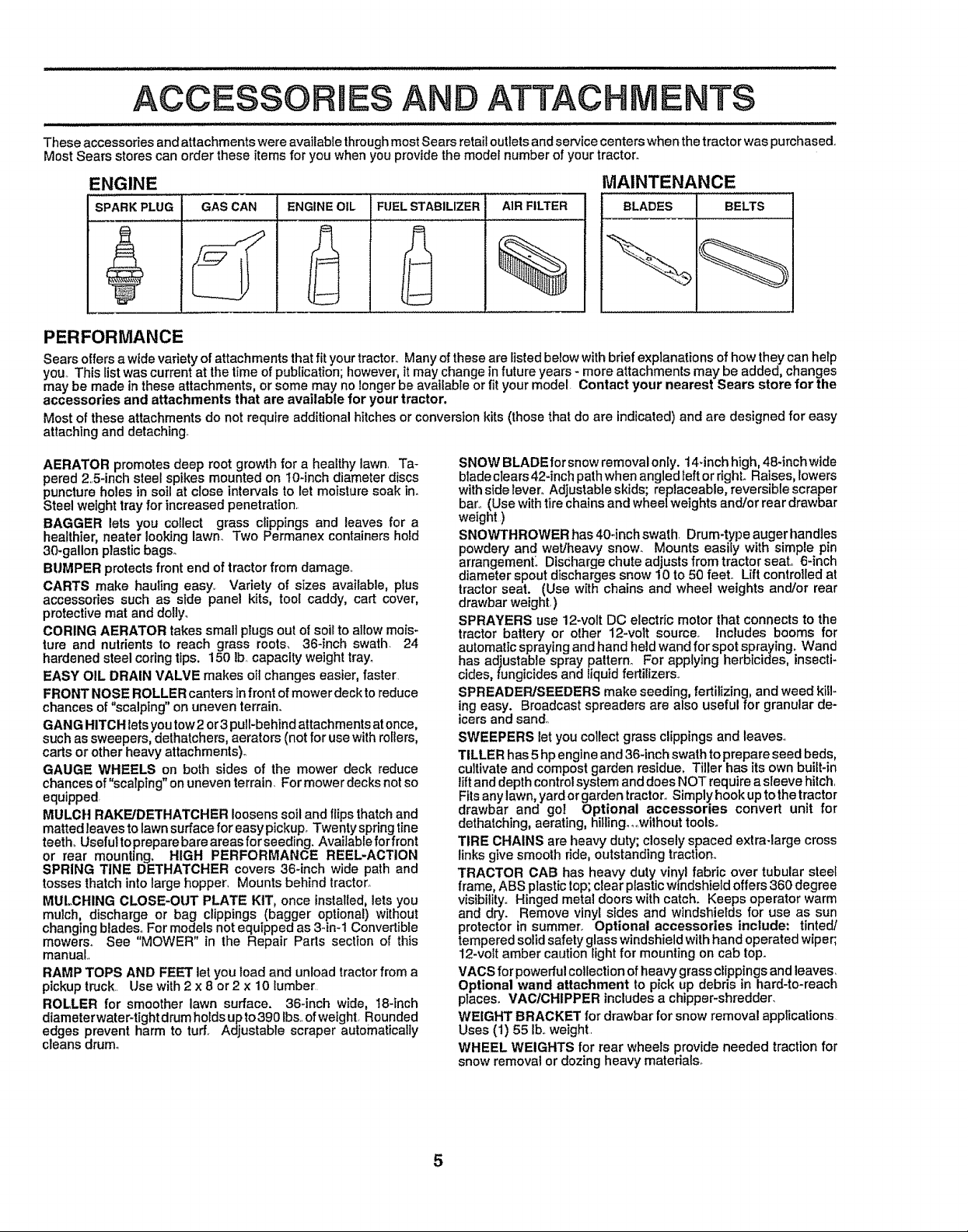
These accessories and attachments were available through most Sears retail outlets and service centers when the tractor was purchased..
Most Sears stores can order these items for you when you provide the model number of your tractor+
ENGINE
SPARKPLUG GAS CAN ENGINEOIL
FUELSTABILIZER AIR FILTER
MAINTENANCE
BLADES BELTS
%
PERFORMANCE
Sears offersa wide variety of attachments that fityourtractor,. Many of theseare listed below with briefexplanations of how they can help
you..This list was current at the time of publication;however,it may change in future years +more attachments may be added, changes
may be made inthese attachments, or some may no longer be available orfityour model. Contact your nearest Sears store for the
accessories and attachments that are available for your tractor.
Mostof these attachments do not require additionalhitches or conversion kits (those that do are indicated) and are designed for easy
attaching and detaching.
AERATOR promotes deep root growth for a healthy lawn. Ta+
pered 25-inch steel spikes mounted on 10-inch diameter discs
puncture holes in soil at close intervals to let moisture soak in+
Steel weight tray for increased penetration.
BAGGER lets you collect grass clippings and leaves for a
healthier, neater looking lawn. Two Permanex containers hold
30-gallon plastic bags.
BUMPER protects front end of tractor from damage..
CARTS make hauling easy. Variety of sizes available, plus
accessories such as side panel kits, tool caddy, cart cover,
protective mat and doliy_
CORING AERATOR takes smal] plugs out of soil to allow mois+
lure and nutrients to reach grass roots. 36-inch swath. 24
hardened steel coring tips. 150 Ib, capacity weight tray°
EASY OIL DRAIN VALVE makes oil changes easier, faster.
FRONT NOSE ROLLER canters in front of mower deck to reduce
chances of "scalping" on uneven terrain.
GANG HITCH letsyou tow2 or3 pull-behind attachments atonce,
such as sweepers, dethatchers, aerators (not for use with rollers,
carts or other heavy attachments)°
GAUGE WHEELS on both sides of the mower deck reduce
chances of"scalping" on uneven terrain. For mower decks not so
equipped
MULCH RAKFJDETHATGHER loosens soil and flips thatch and
matted leaves to lawn surface for easy pickup+ Twenty spring line
teeth° Useful toprepare bare areas for seeding. Available for front
or rear mounting. HIGH PERFORMANCE REEL-ACTION
SPRING TINE DETHATCHER covers 36-inch wide path and
tosses thatch into large hopper. Mounts behind tractor.
MULCHING CLOSE-OUT PLATE KIT, once installed, lets you
mulch, discharge or bag clippings (bagger optional) without
changing blades° For models not equipped as 3-in-1 Convertible
mowers° See "MOWER" in the Repair Parts section of this
manual
RAMP TOPS AND FEET let you load and unload tractor from a
pickuptruck.. Use with 2 x 8 or2 x 10 lumber
ROLLER for smoother lawn surface. 36+inch wide, 18-inch
diameterwater+tight drum hotds upto 390 Ibs+.ofweight. Rounded
edges prevent harm to turf. Adjustable scraper automatically
cleans drum°
SNOW BLADE for snow removal only. 14+inchhigh, 48+inchwide
blade clears 42+inchpath when angledleft or righL Raises, lowers
with side lever° Adjustable skids; replaceable, reversible scraper
bar.. (Use with tire chains and wheel weights and/or rear drawbar
weight )
SNOWTHROWER has 40+inchswath Drum+type auger handles
powdery and wet/heavy snow. Mounts easily with simple pin
arrangement_ Discharge chute adjusts from tractor seal 6-inch
diameter spout discharges snow 10 to 50 feel Lift controlled at
tractor seat. (Use with chains and wheel weights and/or rear
drawbar weight,)
SPRAYERS use 12-volt DC electric motor that connects to the
tractor battery or other 12-volt source, includes booms for
automatic spraying and hand held wand for spot spraying. Wand
has adjustable spray pattern_ For applying herbicides, insecti-
cides, fungicides and liquid fertilizers_+
SPREADER/SEEDERS make seeding, fertilizing, and weed kill-
ing easy. Broadcast spreaders are also useful for granular de-
icers and sand.
SWEEPERS let you collect grass clippings and leaves°
TILLER has 5hp engine and 36-inch swath to prepare seed beds,
cultivate and compost garden residue. Tiller has its own buiLt-in
lift and depth control system and does NOT require a sleeve hitch.
Fitsany lawn, yard or garden tractor..Simply hook upto the tractor
drawbar and gol Optional accessories convert unit for
dethatching, aerating, hitling_,.without tools°
TIRE CHAINS are heavy duty; closely spaced extra-large cross
links give smooth ride, outstanding traction,.
TRACTOR CAB has heavy duly vinyl fabric over tubular steel
frame, ABS plastic top;clear plastic windshield offers 360 degree
visibility. Hinged metat doors with catch. Keeps operator warm
and dry. Remove vinyi sides and windshields for use as sun
protector in summer, Optional accessories include; tinted/
tempered solid safety glass windshield withhand operated wiper;
12-volt amber caution _ightfor mounting on cab top.
VAGS for powerful collection of heavy grass clippings and leaves.
Optional wand attachment to pick up debris in hard-to-reach
places. VAOICHIPPER includes a chipper-shredder.
WEIGHT BRACKET for drawbar for snow removal applications
Uses (1) 55 Ib+.weight.
WHEEL WEIGHTS for rear wheels provide needed traction for
snow removal or dozing heavy materials+
5

CONTENTS OF HARDWARE PACK
Parts Bag contents shown full size
(1) Hex Boit 3/8-16 x I
_Ju,,llJ,,u,ll, i,llllllllllllllll ill u
Parts packed separately in carton
(1) Large Flat Washer
(!) Lockwasher 3/8
@
(1) Hex Bolt 5116-18 x 1-1/4 (1) Locknut 5/16-18
(1) Hex Bolt
1/2-t3 x 1
(1) Washer
17/32 x 1-3/16 x 12 Gauge
Seat
Steering
Wheet
Video
Cassette
Manual
Parts bag contents not shown full size
r;
Mulcher
Steering
Plate
Parts Bag
Boot
(1) Shoulder Bolt 5!16-18
@
(2) Lock Washers #10
(2) Screws #t0 x 5/8 .----_ 1
(2) Weld Nuts #10
(2) Washers 3/16 x 3/4 x 16 Gauge L.I
(2) Hex Bolts 1/4-20 x 3/4
(2) Hex Nuts
1/4-20
(2) Washers
9/32 x 518x t6 Gauge (2) Lock Washers 1/4
(2) Shoulder
Bolts
_(2 (2) Washers 3/8
Steering Wheel
Adapter
(2) Latch Hook
Assemblys
Stope Sheet
6
(_x 7/8 x 14 Gauge
(2) Center-
lockNuts
) Gauge
Wheels
(2) Keys
Steering
Extension
Shaft
Steering
Wheel
Insert

ASSEMBLY
Your new tractor has been assembled at the factory with exceptionof those parts left unassembledfor shipping purposes.
To ensure safe and proper operationof yourtractoral! parts and hardware you assemble must be tightenedsecurely_ Use
the correct tools as necessary to insure ProPertightness.
TOOLS REQUIRED FOR ASSEMBLY
A socket wrench set will make assembly easier_ Standard
wrench sizes are listed,
(1) 5/16"wrench (1) 3/4" Socketw!ddve rachet
(2) 7/16" wrenches Phillips Screwdriver
(1) 1/2" wrench Tire pressure gauge
(1) 9116" wrench Utility knife
When right or left hand is mentioned in this manual, it
means when you are in the operating position (seated
behind the steering wheet)_
TO REMOVE TRACTOR FROM CARTON
UNPACK CARTON
• Remove all accessible loose parts and parts cartons
from carton (See page 6)°
• Cut, from top to bottom, along lines on all four corners
of carton, and tay panels flaL
• Check for any additional loose parts or cartons and
remove°
STEERING
WHEEL
ADAPTER.
LARGE FLAT
WASHER
STEERING
BOOT
BEFORE ROLLING TRACTOR OFF SKiD
ATTACH STEERING WHEEL (See Fig, 1)
ASSEMBLE EXTENSION SHAFT AND BOOT
o Slide extension shaft onto lower steering shaft.. Align
mounting holes in extension and lower shafts and
install 5/16 hex bolt and locknuL Tighten securely°
IMPORTANT: TIGHTEN BOLT AND NUT SECURELY TO
18-22 FT. LBS TORQUE,.
o Place tabs of steering boot over tab slots in dash and
push down to secure_
INSTALL STEERING WHEEL
° Position front wheels of the tractor so theyare pointing
straight forward.
• Slide steering wheel adapter onto steering shaft exten-
sion.
° Position steering wheeJ and sleeve assembly socross
bars are horizontal (left to right) and slide onto adapter.
° Assemble large flat washer, 3/8 iock washer, 3/8 hex
bolt and tighten securely.
• Snap steering wheel insert into center of steering
wheel.
° Remove protective plastic from tractor hood and gdlL
IMPORTANT: CHECK FOR AND REMOVEANY STAPLES
tN SKID THAT MAYPUNCTURE TIRES WHERETRACTOR
IS TO ROLL OFF SKID.
! _._EXTENSION SHAFT
5/16 HEX BOLT
\
5/16 LOCKNUT \
LOWER
STEERING
SHAFT
I
!
0 / I
_, \\ I/
€ t
/
FIG. 1
TO ROLL TRACTOR OFF SKID (See Opera-
tion section for location and function of con-
trols)
° Press liftleverplungerand raise attachment liftlever to
its highest position°
• Release parking brake by depressing clutchtbrake
pedal°
° Place freewheel control in freewheeling position to
disengage transmission (See "TO TRANSPORT" in
the Operation section of this manual),.
° Roll tractor backwards off skid.
° Remove banding holding discharge guard up against
tractor,
7

CONNECT BAI"i'ERY (See Figs. 2 and 3)
BLY
CAUTION: Do not short battery termi-
nals. Before connecting battery, re-
bands, rings, etc.
move metal bracelets, wristwatch
Positive terminal must be connected
first to prevent sparking from acciden-
tal grounding.
uJl.i
• Remove cardboard packing from seat pan and lift seat
pan to raised posRion_
• Open battery box door.
• Remove terminal protective caps and discard.
• Ifthis battery is put into service after month and year
indicated on label (label located between terminals)
charge battery for minimum of one hour at 6-10 amps_
• First connect RED battery cable to positive (+) terminal
with hex bolt, fiat washer, lock washer and hex nut as
shown, Tighten securely.
• Connect BLACK grounding cable to negative (-) termi-
nal with remaining hex bolt, flat washer, lock washer'
and hex nut Tighten securely.
• Close battery box door.
Open battery box door for:
° inspection for secure connections (to tighten hard-
ware).
Inspection for corrosion°
Testing battery.
o
Jumping (if required)..
Periodic charging.
DISCARD
POSITIVE PROTECTIVE
(RED) CABLE CAPS
TERMINAL
SEAT
PAN
BOXDOOR
FIG_ 3
INSTALL SEAT (See Fig. 4)
Adjust seat beforetightening adjustment bolt,,
• Remove cardboard packing on seat pan.
• Place seat on seat pan and assemble shoulder boit.
• Assemble adjustment bolt, lockwasherandflatwasher
loosely. Do not tighten.
• Tighten shoulder' bolt securely.
• Lower seat into operating position and sit on seat.
• Slide seat until a comfortable position is reached which
allows you to press clutch/brake pedal all the way
down.
• Get off seat without moving its adjusted position.
• Raise seat and tighten adjustment bolt securely.,
SEAT
LOCK
HEX
WASHER
NUT
NEGATIVE
(BLACK) CABLE
/
FIG. 2
FLAT
WASHER
HEX
BOLT
SEAT PAN
SHOULDER
BOLT
LOCK WASHER
ADJUSTMENT
BOLT
LARGE FLAT WASHER
FIG, 4
8

ASSEMBLY
CHECK TIRE PRESSURE
The tires onyourtractor were overinflatedat thefactory for
shipping purposes,, Correct tire pressure is important for
best cutting performance°
• Reduce tire pressure to PSi shown in "PRODUCT
SPECIFICATIONS" on page 3 of this manual..
CHECK DECK LEVELNESS
For best cutting results, mower housing should be properly
teveledo See 'q'O LEVEL MOWER HOUSING" in the
Service and Adjustments section of this manual..
CHECK FOR PROPER POSITION OF ALL
BELTS
See the figures that are shown for replacing motion and
mower blade drive belts in the Service and Adjustments
section of this manual.. Verify that the belts are routed
correctly°
CHECK BRAKE SYSTEM
After youlearnhowtooperate your tfactor,checkto see that
the brake is properly adjusted° See "TO ADJUST BRAKE"
in the Service and Adjustments section of this manual.
ASSEMBLE GAUGE WHEELS TO MOWER
DECK (See Fig. 5)
Assemble gauge wheels withtractor on a flat level surface.
° Adjust mower to desired cutting height (See "TO AD-
JUST MOWER CUTTING HEIGHT" in the Operation
section of this manual)°
, With mower in desired height of cut position, gauge
wheels should be assembled so they are slightly off the
ground.. Install gauge wheel in appropriate hole with
shoulder bolt, 3/8' washer and 3/8-16 Iocknut and
tighten securely.
• Repeat for opposite side installing gauge wheel in
same adjustment hole.
GAUGE WHEEL 1
MOUNTING
FIG. 5
_SHOULDER BOLT
9

A
INSTALL MULCHER PLATE
(See Figs. 6 & 7)
- Install two latch hooks to mulcher plate using screw,
washer, lock washer, and weld nut as shown..
NOTE; Pre-assemble weld nut to latch hook by inserting
weld nut from the top with hook pointing down.
• Tighten hardware securely.
° Raise and hold deflector' shield in upright position.
= Place front of mulcher plate over' front of mower deck
opening and slide into place, as shown.
° Hook front latch intohole on front of mower deck.
° Hook rear latch into hole on back of mower deck.
iii1[1111IL ii i iiiii I I
guard from mower. Raise and hold
guard when attaching mulcher plate
I _ CAUTION: Do not remove discharge
TO CONVERT TO BAGGING OR
DISCHARGING
Simply remove mulcher plate and store in a safe place.
Your mower is now ready for discharging or installation of
optionaI grass catcher accessory.
WELD WASHER
LATCH
WASHER
MULCHER
PLATE
and allow it to rest on plate while in
operation.
WELD NUT FROM THE TOP HOOK POINTS DOWN
LOCK
SCREW
HOOK
WELD
LOCK
WASHER
NUT
FIG. 6
LY
DEFLECTOR
SHIELD
LATCH
HOOKS
FIG. 7
,/CHECKLIST
BEFORE YOU OPERATE AND ENJOY YOUR NEW
TRACTOR, WE WISH TO ASSURE THAT YOU RECEIVE
THEBEST PERFORMANCE AND SA TISFA CTION FROM
THIS QUALITY PRODUCT,
PLEASE REVIEW THE FOLLOWING CHECKLIST:
/ All assembly instructions have been cornpleted.
,/ No remaining loose parts incarton_
#" Battery isproperly prepared and charged, (Minimum
1 hour at 6 amps).
V' Seat is adjusted comfortably and tightened securely,
/ Afl tires are properly inflated. (For' shipping purposes,
the tires were overinflated at the factory)_
,I Be sure mower deck is property leveled side-to-side/
front-to-rear for best cutting results_ (Tires must be
properly inflatedfor leveling).
v" Check mower and drive belts. Be sure they are routed
properly around pulleys and inside all belt keepers,
v" Check wiring. See that all connections are still secure
and wires are properlyclamped,
/ Before driving tractor', be sure freewheel control is in
drive position.
WHILE LEARNIIVG HOW TO USE YOUR TRACTOR, PAY
EXTRA A TTENTION TO THE FOLLOWING IMPORTANT
ITEMS:
J Engine oil isat proper' level
J" Fuel tank is filled with fresh, cJean, regular unleaded
gasoline.
,/ Become familiar "with all controls - their' location and
function. Operate them before you start the engine_
J Be sure brake system is in safe operating condition_
v" tt isimportant to purge the transmission before operat-
ingyour tractor for the first time. Follow proper starting
and transmission purging instructions(See'q'O START
ENGINE" and "PURGE TRANSMISSION" in the Op_
eration section of this manual).
10

OPERATION
These symbols may appear on your product or in literature supplied with the product. Learn and understand their meaning..
REVERSEBATTERY CAUTION OR FORWARD FAST SLOW
WARNING
ENGINE ON ENGINE OFF OIL PRESSURE CLUTCH LIGHTS ON LIGHTS OFF
MOWER LIFT
CHOKEFUEL MOWER HEIGHT
REVERSE NEUTRAL
ATTACHMENT
CLUTCH ENGAGED
If _°_ I
DIFFERENTIAL PARKING BRAKE UNLOCKED
LOCK LOCKED
L
HIGH
ATTACHMENT
CLUTCH DISENGAGED
LOW PARKING BRAKE
IGNITION
DANGER, KEEP HANDS AND FEET AWAY
HYDROSTATIC FREE WHEEL
(Hydro Models only)
11
OPERATION
KNOW YOUR TRACTOR
READ THIS OWNER'S MANUAL AND SAFETY RULES BEFORE OPERATING YOUR TRACTOR
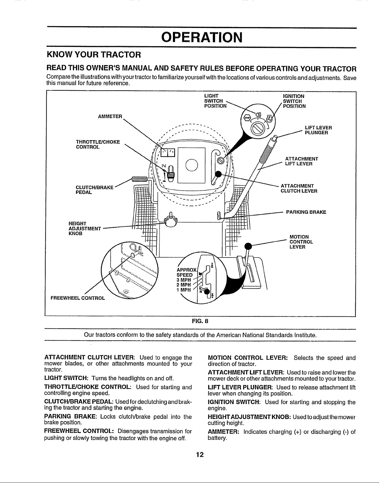
Compare the illustrationswithyourtractor to familiarize yourself with the locations of various controls and adjustrnents_ Save
this manual for future reference°
LIGHT IGNITION
SWITCH SWITCH
AMMETER
THROTTLFJCHOKE
CONTROL
©
POSITION
LIFT LEVER
PLUNGER
ATTACHMENT
LIFT LEVER
CLUTCHJBRAKE
PEDAL
HEIGHT'
ADJUSTMENT
KNOB
APPROX
SPEED
3 MPH
2 MPH
1MPH
FREEWHEEL CONTROL
Our tractors conform to the safety standards of the American National Standards Institute.
ATI'ACHMENT CLUTCH LEVER: Used to engage the
mower blades, or' other attachments mounted to your
tractor.
LIGHT SWITCH: Turns the headlights on and off,.
THROTTLE/CHOKE CONTROL: Used for starting and
controlling engine speed°
CLUTCHIBRAKE PEDAL: Used for declutching and brak-
ingthe tractor and starting the engine°
PARKING BRAKE: Locks clutch/brake pedal into the
brake position,,
FREEWHEEL CONTROL: Disengages transmission for
pushing or'slowly towing the tractor with the engine off.,
ATTACHMENT
CLUTCH LEVER
PARKING BRAKE
MOTION
CONTROL
LEVER
FIG, 8
MOTION CONTROL LEVER: Selects the speed and
direction of tractor,
ATTACHMENT LIFT LEVER: Used to raise and lower the
mower deck or other'attachments mounted to your tractor,
LIFT LEVER PLUNGER: Used to release attachment lift
lever when changing itsposition.
IGNITION SWITCH: Used for starting and stopping the
engine.
HEIGHTADJUSTMENT KNOB: Usedto adjustthernower
cutting heighL
AMMETER: Indicates charging (+) or discharging (-) of
battery.
12

OPERATION
The operation of any tractor can result in foreign objects thrown into the eyes, which can
result in severe eye damage. Always wear safety glasses oreye shields while operating your
tractor or performing any adjustments or repairs. We recommend a wide vision safety mask
over the spectacles or standard safety glasses.
HOW TO USE YOUR TRACTOR
TO SET PARKING BRAKE (See Fig, 9)
Your tractor is equipped with an operator presence sensing
switch. When engine is running, any attempt by the
operator to leave the seat without first setting the parking
brake will shut off the engine°
• Depress clutch/brake pedal intofull "BRAKE" position
and hold.
° Place parking brake lever in"ENGAGED" positionand
release pressure from clutch/brake pedal Pedalshould
remain in "BRAKE" position. Make sure parking brake
will hold tractor secure.
ATTACHMENT CLUTCH LEVER
THROTTLE/
CHOKE
CONTROL
"BRAKE"
POSITION
CLUTCH/BRAKE PEDAL
"DRIVE" POSITION
STOPPING (See Fig. 9)
MOWER BLADES -
" Move attachment clutch lever to "DISENGAGED" po-
sition.
GROUND DRIVE -
- Depress clutch/brake pedal intofuII"BRAKE" position.
° Move motion control lever to neutral (N) position°
IMPORTANT: THE MOTION CONTROL LEVER DOES
NOT RETURN TO NEUTRAL (N) POSITION WHEN THE
CLUTCH/BRAKE PEDAL iS DEPRESSED
ENGINE *
- Move throttle control to slow (._8_) position_
NOTE= Failure to move throttle control to slow (._)
position and allowing engine to idle before stopping may
cause engine to "backfire".
"ENGAGED" POSITION
PARKING BRAKE
'ENGAGED"POSITION
MOTION CONTROL
LEVER
"DISENGAGED"
k POSITION
HEIGHT ADJUSTMENT KNOB
FIG. 9
- Turn ignitionkey to "OFF" position and remove key.
Always remove key when leaving tractor to prevent
unauthorized use_
° Never use choke to stop engine.
NOTE: Under certain conditions when tractor is standing
idlewith the engine running, hot engine exhaust gases may
cause "browning" of grass_ To eliminate this possibility,
always stop engine when stopping tractor on grass areas.
CAUTION: Always stop tractor com-
pletely, as described above, before leav-
IA .............
ing the operator's position; to empty
grass catcher, etc.
TO USE THROTTLE CONTROL (See Fig. 9)
Always operate engine at full throttle.
• Operating engine at less than full throttle reduces the
battery charging rate.
° Full throttle offers the best bagging and mower perfor-
mance.
TO MOVE FORWARD AND BACKWARD (See
Fig, 9)
The direction and speed of movement is controlled by the
motion control lever,.
• Start tractor with motion control lever in neutral (N)
position.
• Release parking brake and clutch/brake pedal.
° Slowly move motion control lever to desired position.
TO ADJUST MOWER CUTTING HEIGHT (See
Fig. 9)
The cutting height iscontrolled by turning the height adjust-
ment knob in desired direction.
• Turn knob clockwise ((-'_1)to raise cutting height°
° Turn knob counterclockwise (p--'.,)to lower cutting
height°
The cutting height range isapproximately 1-1/2" to 4". The
heights are measured from the ground to the blade tip with
the engine not running. These heights are approximate
and may vary depending upon soil conditions, height of
grass and types of grass being mowed,
° The average lawn should be cut to approximately 2-1/2
inches during the cool season and to over 3 inches
during hot months, For healthier and better looking
lawns, mow often and after moderate growth,
° For best cutting performance, grass over 6 inches in
height should be mowed twice. Make the first cut
relatively high; the second to desired height.
13
OPERATION
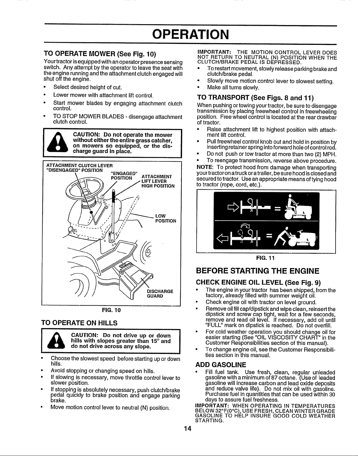
TO OPERATE MOWER (See Fig. 10)
Your tractor isequipped with an operator presencesensing
switch. Any attempt by the operator' to leave the seat with
the engine running and the attachment clutch engaged will
shut off the engine.
• Select desired height of cut.
° Lower mower with attachment lift control.
• Start mower blades by engaging attachment clutch
control.
TO STOP MOWER BLADES - disengage attachment
c_utchcontrol.
without either the entire grass catcher, i
on mowers so equipped, or the dis- J
cAUTION: Do notoperate the mower ........1
charge guard in place, I
ATTACHMENT CLUTCH LEVER
"DISENGAGED" POSITION
°ENGAGED"
POSITION ATTACHMENT
j LIFr LEVER
HIGH POSITION
LOW
POSITION
IMPORTANT: THE MOTION CONTROL LEVER DOES
NOT RETURN TO NEUTRAL (N) POSITION WHEN THE
CLUTCHfBRAKE PEDAL IS DEPRESSED.
• To restart movement, slowly release parking brake and
clutch/brake pedal
° Slowly move motion control lever to slowest setting+
• Make all turns slowly..
TO TRANSPORT (See Figs. 8 and 11)
When pushingor'towingyour'tractor, be sure todisengage
transmissionby placingfreewheel control infreewheeling
position. Free wheel controlis located at the rear drawbar
oftractor.
• Raise attachment lift to highest position with attach-
ment liftcontrol.
• Pullfreewheel controlknob out and hold inpositionby
inserting retainer'springintoforward hole of controlrod.
• Do not push or'tow tractor at more than two (2) MPH.
Ii
• To reengage transmission,reverse above procedure.
NOTE: To protecthoodfrom damage when transporting
yourtractoron atruckoratrailer,besure hood is closedand
securedtotractoroUsean appropriate means oftyinghood
to tractor (rope, cord, etc.)+
BEFORE STARTING THE ENGINE
_)_DGIuSCRHDARGE
FIG. 10
TO OPERATE ON HILLS
CAUTION: Do not drive up or down
iA.....................
• Choose the slowest speed before starting up or down
hills+
• Avoid stopping or changing speed on hills+
° if slowing is necessary, move throttle control lever to
slower position.
• tf stopping is absolutely necessary', push clutch/brake
peaal quickly to brake position and engage parking
brake+
• Move motion control lever to neutral (N) position°
hills with slopes greater than 15° and
do not drive across any slope.
CHECK ENGINE OIL LEVEL (See Fig. 9)
• The engine inyour tractor'has been shipped, from the
factory, already filled with summer weight oil..
• Check engine oil with tractor on level ground°
• Remove oil fill cap/dipstlck and wipe clean, reinsert the
dipstick and screw cap tight, walt for a few seconds,
remove and read oil level. If necessary, add oil until
"FULL" mark on dipstick is reached+ Do not overfill
• For' cold weather-operation you should change o+lfor
easier starting (See "OIL VISCOSITY CHART" in the
Customer Responsibilities section of this manual)+
• To change engine oil, see the Customer' Responsibili-
ties section inthis manual
ADD GASOLINE
• Fill fuel tank. Use fresh, clean, regular unleaded
gasolinewitha minimum of 87 octane.. (Use of leaded
gasolinewillincrease carbon and lead oxidedeposits
and reduce valve life)+ Do not mix oil with gasoline.
Purchasefuel in quantities that can be used within30
days to assure fuel freshness+
IMPORTANT: WHEN OPERATING IN TEMPERATURES
BELOW 320F(O°C),USE FRESH, CLEAN WINTER GRADE
GASOLINE TO HELP INSURE GOOD COLD WEATHER
STARTING+
14
FIG. 11

OPERATI
WARNING: Experience indicates that alcohol blended
fuels (called gasohol or using ethanol or methanol) can
attract moisture which leads to separation and formation of
acids during storage° Acidic gas can damage the fuel
system of an engine while in storage° To avoid engine
problems, the fuel system should be emptied before stor-
age of 30 days or longer. Drain the gas tank, start the
engine and let it run until the fuel lines and carburetor are
empty. Use fresh fuel next season° See Storage Instruc-
tions for additional information.. Never use engine or
carburetor cleaner products in the fuel tank or permanent
damage may occur°
Fill to bottom of gas tank
filler neck. Do not overfill. Wipe off any
spilled oil or fuel Do not store, spill or
use gasoline near an open flame.
TO START ENGINE (See Fig. 9)
When startingthe engine for the first time or if the engine
has runout of fuel, it willtake extra cranking time to move
fuel from the tank to the engine°
o Depressclutch/brake pedal and set parking brake.
o Place motioncontrollever in neutral (N) position.
• Move attachment clutchto "DISENGAGED" position°
o Move throttlecontrolto choke (N) position.
Note: Before starting, read the warm and cold starting
procedures below.
o Insertkeyintoignitionandturnkeyc!ockwiseto"START"
positionand release key as soon as enginestarts. Do
not run starter continuouslyfor more than fifteen sec-
onds per minute_ If the engine does not start after
several attempts, move throttle control to fast (,_)
position,waitafew minutesand tryagain.. Ifenginestill
does not start, move the throttle controlback to the
choke (N) positionand retry°
WARM WEATHER STARTING (50° F and above)
° When enginestarts, movethe throttle control tothe fast
(,_) position°
. The attachments and ground drive can now be used. if
theengine does not accept the load, restart the engine
and allow it to warm up for one minute using the choke
as described above..
COLD WEATHER STARTING ( 50° F and below)
° When engine starts, allow engine to run with the throttle
control inthe choke (N) position untii the engine runs
roughly, then move throttle control tofast (,_) position.
This may require an engine warm-up period from
several seconds to several minutes, depending on the
temperature..
HYDROSTATIC TRANSMISSION WARM UP
° Before driving the unit in cold weather, the transmis-
sion should be warmed up as follows:
= Be sure the tractor is on level ground.
o Place the motion control lever in neutral..
Release the parking brake and letthe clutch/brake
slowly return to operating position.
° Allow one minute for transmission to warm up_
This can be done during the engine warm up
period.
° The attachments can also be used during the engine
warm-up period after thetransmission has been warmed
up°
NOTE: If at a high altitude (above 3000 feet) or in cold
temperatures (below 32 F) the carburetor fuel mixture may
need to be adjusted for best engine performance. See "TO
ADJUST CARBURETOR" in the Service and Adjustments
section of this manual,.
PURGE TRANSMISSION
freewheel leverwhile the engine is run-
CAUTION: Never engage or disengage
ning.
To ensure proper operation and performance, itis recom-
mended that the transmission be purged before operating
tractor for the first time° This procedure will remove any
trapped air inside the transmission which may have devel-
oped during shipping of your tractor.
IMPORTANT: SHOULD YOUR TRANSMISSION REQUIRE
REMOVAL FOR SERVICE OR REPLACEMENT, IT
SHOULD BE PURGED AFTER REINSTALLATION
BEFORE OPERATING THE TRACTOR,
• Place tractor safely on level surface with engine off and
parking brake set,,
° Disengage transmission by placing freewheel control
in freewheeling position (See "TO TRANSPORT" in
this section of manual).
° Sitting in the tractor seat, start engine. After the engine
is running, move throttle control to slow (,_!) position.
With motion control lever inneutral (N) position, slowly
disengage clutch/brake pedal.
° Move motion control lever to full forward position and
hold for five (5) seconds. Move lever to full reverse
position and hold for five (5) seconds,. Repeat this
procedure three (3) times,.
NOTE: Dudng this procedure there will be no movement of
drivewheels. The air isbeing removed from hydraulic drive
system..
• Move motion control leverto neutral (N) position° Shut-
off engine and set parking brake.
• Engage transmission by placing freewheel control in
driving position (See'q'O TRANSPORT" inthis section
of manual)°
° Sittinginthetractor seat, startengine. Afterthe engine
is running, move throttle control to half (1/2) speed.
With motion control lever inneutral (N) position, slowly
disengage clutch/brake pedal°
• Slowly move motion control lever forward, after the
tractor moves approximately five (5) feet, slowly move
motion control lever to reverse position. After the
tractor moves approximately five (5) feet return the
motion control levertothe neutral (N) position. Repeat
this procedure with the motion control lever three (3)
times..
° Your tractor is now purged and now ready for normal
operation.
15
OP
MOWING TIPS
i
Tire chains cannot be used when the mower housing is
attached to tractor.
• Mower should be properly leveled for best mow!,ng
performance. See q'O LEVEL MOWER HOUSING in
the Service and Adjustments section of this manual
. The left hand side of mower should be used for trim-
ming.
• Drive so that clippings are discharged onto the area
that has been cut. Have the cut area to the right ofthe
machine. This will result in a more even distribution of
clippings and more uniform cutting°
o When mowing large areas, start by turning to the right
so that clippings will discharge away from shrubs,
fences, driveways, etc. After one or two rounds, mow
in the opposite direction making left hand turns until
finished (See Fig. 12 )o
• If grass isextremely tall, it should be mowed twice to
reduce load and possible fire hazard from dried clip-
pings. Make first cut relatively high; the second to the
desired heighL
= Do not mow grass when it is wet° Wet grass will plug
mower and leave undesirable clumps. Allow grass to
dry before mowing_
• Always operate engine at full throttle when mowing to
assure better mowing performance and proper dis*
charge of material Regulate ground speed by select-
ing a low enough gear to give the mower cutting
performance as well as the quality of cut desired.
• When operating attachments, select a ground speed
that will suit the terrain and give best performance of
the attachment being used°
MULCHING MOWING TIPS
IMPORTANT: FOR BEST PERFORMANCE, KEEP
MOWER HOUSING FREE OF BUILT*UP GRASS AND
TRASH. CLEAN AFTER EACH USE,
The special mulching blade will recut the grass clip-
pings many times and reduce them in size so that as
they fall onto the lawn they will disperse intothe grass
and not be noticed° Also, the mulched grass will
biodegrade quickly to provide nutrients for the lawn.
Always mulch with your highest engine (blade) speed
as this will provide the best recutting action of the
blades,,
. Avoid cutting your lawn when it iswet. Wet grass tends
to form clumps and interfereswith the mulching action_
The best time to mow your' lawn is the early afternoon.
At this time the grass has dried and the newly cut area
will not be exposed to the direct sun°
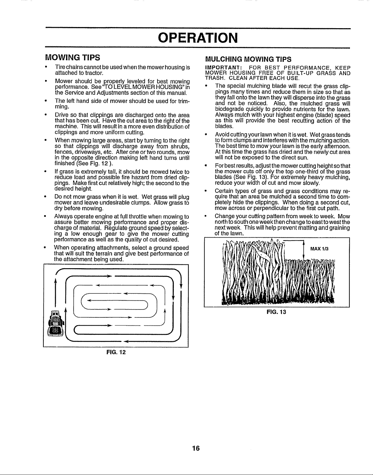
° For best results, adjust the mower cutting height so that
the mower cuts off only the top one-third of the grass
blades (See Fig. 13). For extremely heavy mulching,
reduce your width of cut and mow slowly.
• Certain types of grass and grass conditions may re-
quire that an area be mulched a second time to com-
pletely hide the clippings. When doing a second cut,
mow across or perpendicular to the first cut path.
• Change your cutting pattern from week to week. Mow
north to south one week then change to east towest the
next week_ This will help prevent matting and graining
of the lawn.
MAX 1/3
f
1111±
FIG. 13
FIG, 12
16

CUSTOMER RESPONSIBtL ES
' M_JNTE'NANCE SCHEDULE .,,_'___./__o_//_,,'f
AS YOUCOMPLETE _'___O_,_=0_ €0"__"_._ _._ _. _._._ _.,_,_ ._O_
REGULAR SERVICE ..... ._" __.,_ SERVICE DATES
CheckBrakeOPorat_on _ i . . ,
Check Tire Pressure _'
JT 13'hockfor Loose Fasteners _#t
iR Sharpe_Replace Mower Blades _#_',
iA
iC LU,,€,ti0,Chart V' v"
T CheckBatteryLevel;Recharge " = ............... _ ................. i,,i
o Crea.Ba.eryandTer_,°a,s........... _' .... [,_' .[_
R Check Transaxle Cooling _ ...................... ! ........................
Adjust Blade Belt(s) Tension _#'s
Adjust Motion Drive Belt(s) Tension _Js
Check Engine Ofl Level _
cha,ge Engine Oil il_ _2,3 '_ ......
Ciea°AirF,!er.......... J_ ,.,
N CleanAirSo,reen ...._
G Inspect Muffier/Spark Arrester
I Replace Oil Filter (If equipped) _.2
N €ie_n EnginecoolinoFins _,'_= ........
E Rep,acesp,rkPi.g......................................... v' v" .....
Replace Air Filter Paper Cartridge _#'2
Replace Fuel Filter _#'
t _Change more often when operatingunder a heavy lead or tn high ambient temperatures
2 - Service more often when operatingin dirty or dusty conditions
3 - l! equipped with oil filter, change olt every 50 hours
4 - Replace blades more often when mowing _nsandy soil
v'
v', ...................v'
5 - II equippedwith adjustable system
6 - Not requi_ed ifequipped with maintenance-free battery
7 * Tighten frontaxIa pivot boll to 35 ft-1bs, maximum
Do net overt_ghten
GENERAL RECOMMENDATIONS
The warranty on this tractor does not cover itemsthat have
been subjected to operator abuse or negligence,. To
receive full value from the warranty, operator must maintain
tractor as instructed in this manual
Some adjustments wilt need to be made periodically to
properly maintain your tractor.
All adjustments in the Service and Adjustments section of
this manual should be checked at least once each season.
Once a year you should replace the spark plug, clean
or replace air filter, and check blades and belts for
wear_ A new spark plug and clean air filter assure
proper air-fuel mixture and help your engine run better
and last longer.
BEFORE EACH USE
• Check engine oil level,,
o Check brake operation.
• Checktire pressure.
° Check for loose fasteners,.
LUBRICATION CHART
_) SPINDLE ZERK _IDLE ZERK(_)
(_) t: "FRONT WHEEL (_)
BEARING ZERK BEARING ZERK
ENGINE(_)
@
CLUTCH
PIVOT(S)
(_) SAE 30 OR 10W30 MOTOR OIL
(_) GENERAL PURPOSE GREASE
(_) REFER TO CUSTOMER RESPONSIBILITIES "ENGINE" SECTION
IMPORTANT: DO NOT OIL OR GREASE THE PIVOT POINTS
WHICH HAVE SPECIAL NYLON BEARINGS. VISCOUS LUBRi-
CANTS WILL ATTRACT DUST AND Of RT THAT WILL SHORTEN
THE LIFE OF THE SELF-LUBRICATING BEARINGS. IF YOU
FEEL THEY MUST BE LUBRICATED, USE ONLY A DRY, POW-
DERED GRAPHITE TYPE LUBRICANT SPARINGLY.
17

ill illlllllllllJllllllllJllllJllllJllllJllllllllllllllllii iiilllJlllllilll ii ii illll i iJ iiii iiii i i/ i i
CUSTOMER RESPONSIBILITIES
TRACTOR
Always observe safety rules when performing any mainte-
nance.
BRAKE OPERATION
if tractor requires more than six (6) feet stopping distance
at high speed in highest gear, then brake must be adjusted.
(See "TO ADJUST BRAKE" in the Service and Adjust-
rnents section of this manual).
TIRES
• Maintain proper air pressure in all tires (See "PROD-
UCT SPECIFICATIONS" on page 3 of this manual).
° Keep tires free of gasoline, oil, or insect control chemi-
cals which can harm rubber.
• Avoid stumps, stones, deep ruts, sharp objects and
other hazards that may cause tire damage.
BLADE CARE
For'best results mower blades must be kept sharp° Re-
place bent or damaged blades_
BLADE REMOVAL (See Fig. 14)
• Raise mower to highest position to allow access to
blades.
• Remove hex bolt, lock washerand flat washer securing
blade.
° Install new or resharpened blade with trailing edge up
towards deck as shown.
° Reassemble hex bolt, lock washer and flat washer in
exact order as shown,
° Tighten bolt securely (30-35 FL Lbs. torque).
IMPORTANT: BLADE BOLTISGRADE 8 HEATTREATED.
NOTE: We do notrecommend sharpening blade- but ifyou
do, be sure the blade is balanced.
TO SHARPEN BLADE (See Fig. 15)
Care should be taken to keep the blade balanced, An
unbalanced blade will cause excessive vibration and even-
tual damage to mower and engine.
° The blade can be sharpened with a file or on a gdnding
wheel° Do not attempt to sharpen while on the mower.
• To check blade balance, you will need a 5/8" diameter'
steel bolt, pin, or a cone balancer,, (When using a cone
balancer, follow the instructions supplied with hal-
anGer).
° Slide blade on to an unthreaded portion of the steel bolt
or'pin and hold the bolt or pin parallel with the ground.
if blade is balanced, it should remain in a horizontal
position_ If either end of the blade moves downward,
sharpen the heavy end until the blade is balanced°
NOTE: Do not use a nail for balancing blade. The lobes of
the center hole may appear to be centered, but are not.
CENTER HOLE / /
518. LADE
FIG. 15
BLADE MANDREl,.
TRAILtNG EDGE
FLAT WASHER %_.
HEX BOLT
(GRADE
*A GRADE 8 HEAT TREATED BOLT CAN BE
IDENTtRED BY SIX LINES ON THE BOLT HEAD,
FIG. 14
ASSEMBLY
18
 Loading...