

Craftsman 917259290 Owner’s Manual

[R UFTZ
MODEL NUMBER 917.259290
• Assembly
• Operation
• Customer Responsibilities
• Service and Adjustments
• Repair Parts
OWNER'S MANUAL
CAUTION: Read and follow all safety rules and instructions before operating this equipment.
FOR CONSUMER ASSISTANCE HOT LINE, CALLTHIS TOLL FREE NUMBER: 1-800-659-5917
IIIIIIIIII I III IIIIII
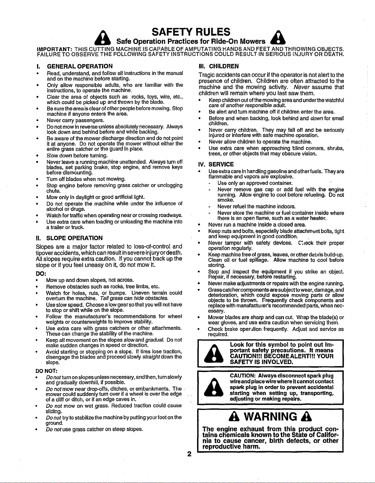
Safe Operation Practices for Ride-On Mowers
SAFETY RULES
IMPORTANT: THIS CUTTING MACHINE IS CAPABLE OF AMPUTATING HANDS AND FEET AND THROWING OBJECTS.
FAILURE TO OBSERVE THE FOLLOWING SAFETY INSTRUCTIONS COULD RESULT IN SERIOUS INJURY OR DEATH.
I. GENERAL OPERATION
• Read, understand, and follow all instructions inthe manual
and on the machine before starting.
• Only allow responsible adults, who are familiar with the
instructions, to operate the machine.
• Ciear the area of objects such as rocks, toys, wire, etc.,
which could be picked up and thrown bythe blade.
• Be surethe area isclear of other people before mowing. Stop
machine if anyone enters the area.
• Never carry passengers.
• Donot mow in reverse unless absolutely necessary. Always
look clownand behind before and while backing.
• Beaware of the mower discharge directionand do notpoint
it at anyone. Do not operate the mower without either the
entire grass catcher or the guard in place.
• Slow down before turning.
• Never leave a running machine unattended. Always turn off
blades, set parking brake, stop engine, and remove keys
before dismounting.
• Turn off blades when not mowing,
• Stop engine before removing grass catcher or unclogging
chute.
• Mow only in daylight or good artificial light.
• Do not operate the machine while under the influence of
alcohol or drugs.
• Watch for traffic when operating near or crossing roadways.
• Use extra care when loading or unloading the machine into
a trailer or truck.
!1. SLOPE OPERATION
Slopes are a major factor related to loss-of-control and
tipover accidents, which can result in severe injury or death.
All slopes require extra caution. If you cannot back up the
slope or if you feel uneasy on it, do not mow it.
DO:
• Mow up and down slopes, not across.
• Remove obstacles such as rocks, tree limbs, etc.
* Watch for holes, ruts, or bumps. Uneven terrain could
overturn the machine. Tall grass can hide obstacles.
• Use slowspeed. Choose a low gear so that you will not have
to stop or shift while on the slope.
• Follow the manufacturer's recommendations for wheel
weights or counterweights to improve stability.
• Use extra care with grass catchers or other attachments.
These can change the stability of the machine.
• Keep all movement on the slopes slow and gradual Do not
make sudden changes in speed or direction.
• Avoid starting or stopping on a slope. If tires lose traction,
disengage the blades and proceed slowly straight down the
slope.
DO NOT:
• Donot turn on slopesunlessnecessary,and then,turnslowly
and gradually downhill,if possible.
• Do notmow near drop-offs,ditches, or embankments. The-
mowercould suddenly turnover if a wheel is over the edge .
ofa cliffor ditch, or ifan edge caves in.
• Do not mow on wet grass. Reduced traction could cause
sliding.
• Do not try to stabilizethemachine by putting yourfoot onthe
ground.
• Do not use grass catcher on steep slopes.
IlL CHILDREN
Tragic accidents can occur if the operator is not alert to the
presence of children. Children are often attracted tothe
machine and the mowing activity. Never assume that
children will remain where you last saw them.
• Keep childrenout ofthe mowingarea and under thewatchful
care of another responsible adult.
• Be alert and turn machine off ifchildren enter the area.
• Before and when backing, look behind and down for small
children.
• Never carry childran. They may fall off and be seriously
injuredor interferewith safe machine operation.
• Never allow childrento operate the machine.
• Use extra care when approaching blind comers, shrubs,
trees, or other objectsthat may obscure vision.
IV.
SERVICE
o
Use extra care inhandlinggasoline andotherfuels. Theyare
flammable and vapors are explosive.
Use only an approved container.
Never remove gas cap or add fuel with the engine
running. Allow engine to cool before refueling. Do not
smoke.
- Never refuel the machine indoors.
- Never store the machine orfuel container inside where
there is an open flame, such as a water heater.
o
Never run a machine inside a closed area,
Keep nuts and bolts, especially blade attachment bolts, tight
and keep equipment in good condition.
Never tamper with safety devices. C',leck their proper
operation regularly.
Keep machine free of grass, leaves, or other debris build-up.
Clean oil or fuel spillage. Allow machine to cool before
storing.
Stop and inspect the equipment if you strike an object.
Repair, if necessary, before restarting.
Never make adjustments or repairs with the engine running.
t
Grass catchercomponents are subjecttowear, damage, and
deterioration, which couid expose moving parts or allow
objects to be thrown. Frequently check components and
replace with manufacturer's recommended parts, when nec-
essary.
Mower blades are sharp and can cut. Wrap the blade(s) or
wear gloves, and use extra caution when servicing them.
Check brake oper:_tion frequently. Adjust and service as
required.
III i|1 i
Look for this symbol to point out im-
portant safety precautions. It means
CAUTION!!! BECOMEALERT!!! YOUR
SAFETY IS INVOLVED.
I IIIIIII i L
i i Hi
CAUTION: Always disconnect spark plug
wireand placewirewhere itcannot contact
spark plug in order to prevent accidental
starting when setting up, transporting,
adjusting Or making repairs.
] i
& WARNING A
The engine exhaust from this product con-
tains chemicals known to the State of Califor-
nia to cause cancer, birth defects, or other
reproductive harm.
IIII II iiiiiirl
2

CONGRATULATIONS on your purchase of a Sears
Tractor. It has been designed, engineered and manufac-
tured to give you the best possible dependability and
performance.
Should you experience any problem you cannot easily
remedy, please contact your nearest Sears Authorized
Service Center/Department. We have competent, well-
trainedtechniciansand the propertoolstoserviceor repair
this tractor.
Please read and retain this manual. The instructionswill
enable you to assemble and maintainyour unitproperly.
Always observethe "SAFETY RULES".
MODEL
NUMBER 917.259290
SERIAL
NUMBER
DATE OFPURCHASE
THE MODEL AND SERIAL NUMBERS WILLBE FOUND
ON A PLATE UNDER THE SEAT.
YOU SHOULD RECORD BOTHSERIAL NUMBER AND
DATE OF PURCHASE AND KEEP IN A SAFE PLACE
FOR FUTURE REFERENCE.
PRODUCT SPECIFICATIONS
HORSEPOWER: 13.5
GASOLINE CAPACITY 1.25 GALLONS
AND TYPE: UNLEADED REGULAR
OIL TYPE (API-SF/SG): SAE 30 (above 32°F)
SAE 5W-30 (below 32°F)
OIL CAPACITY: 3 PINTS
SPARK PLUG: CHAMPION RJ19LM
(GAP: .030") STD361458
VALVE CLEARANCE: INTAKE: .005" - .007"
EXHAUST: .009" - .011"
GROUND SPEED (MPH): FORWARD:
1st 1.0
2nd 1.3
3rd 2.1
4th 3.1
5th 4.0
6th 5.1
REVERSE: 1.6
TIRE PRESSURE: FRONT: 14 PSI
REAR: 12 PSI
CHARGING SYSTEM: 3 AMPS BATTERY
5 AMPS HEADLIGHTS
MAINTENANCE AGREEMENT
A Sears Maintenance Agreement is available on this prod-
uct. Contact your nearest Sears store for details.
CUSTOMER RESPONSIBILITIES
° Read and observe the safety ruIes.
• Followa regular schedule in maintaining, caring for and
using your tractor.
• Followthe instructions under"Customer Responsibili-
ties" and "Storage" sections of this owneCs manual.
WARNING: This tractor is equipped with an internal
combustion engine and should not be used on or near any
unimproved forest-covered, brush-covered or grass-cov-
ered land unless the engine's exhaust system is equipped
BATTERY: AMP/H R: 25
MIN. CCA: 190
CASE SIZE: U1R
BLADE BOLT TORQUE: 30-35 FT. LBS.
witha spark arrester meeting applicable local or state laws
(if any). Ifa spark arrester is used, it should be maintained
in effective working order by the operator.
In the state of California the above is required by law
(Section 4442 of the California Public Resources Code).
Other states may have similar laws. Federal laws apply on
federal lands. Aspark arrester for the muffler is available
through your nearest Sears Authorized Service Center/
Department (See REPAIR PARTS section ofthis manual).
LIMITED TWO YEAR WARRANTY ON CRAFTSMAN RIDING EQUIPMENT
For two (2) years from the date of purchase, if this Craftsman Riding Equipmentis maintained, lubricatedand tuned up according
to the instructions in the owner's manual, Sears wilt repair or replace, free of charge, any parts found to be defective in material or
workmanship.
This Warranty does not cover:
• Expendable items which become worn during normal use, such as blades, spark plugs, aircleaners, belts, etc.
• Tire repTacement or repair caused by punctures from outside objects, such as nails, thorns, stumps, or glass.
• Repairs necessary because of operator abuse, negligence, improper storage or accident orthe faiiure to maintain the
equipment according to the instructions contained inthe owner's manual.
• Riding equipment used for commercial or rental purposes.
LIMITED 90 DAY WARRANTY ON BATTERY
For ninety (90) days from date of pumhase, if any battery included with this riding equipment proves defective in material or
workmanshipand our testingdetermines the battery wilt not hoidacharge, Sears will replace the battery at no charge.
IN-HOME WARRANTY SERVICE ONLYOUR CRAFTSMAN RIDING EQUIPMENT IS AVAILABLE AT NO-CHARGE FOR 30
DAYS FROM THE DATE OF PURCHASE; PLEA,SE CONTACT YOUR NEAREST SERVICE CENTER; AFTER 30 DAYS FROM
THE DATE OF PURCHASE, WARRANTY SERVICE IS AVAILABLE BYTAKING YOUR CRAFTSMAN RIDING EQUIPMENT TO*
YOUR NEAREST SEARS SERVICE CENTER. (iN-HOME WARRANTY SERVICE WILL STILL BE AVAILABLE AFTER 30 DAYS
FROM THE DATE OF PURCHASE BUT A STANDARD TRIP CHARGE WILL APPLY.) THIS WARRANTY APPLIES ONLY
WHILE THIS PRODUCT IS IN THE UNITED STATES.
ThisWarranty gives you specific legal rights,and you may aTsohave otherrightswhich may van! from state to state.
SEARS, ROEBUCK AND CO., D/817 WA, HOFFMAN ESTATES, IL 60179
IIII] I iiiii I I I
3
.............................TABLE O CONTEN:FS ..........................
i i i,,llll, ,,,,,,,,,,,,,,,,,,,,,,, .......................
SAFETY RULES ............................................................ 2
PRODUCT SPECIFICATIONS ...................................... 3
CUSTOMER RESPONSIBILITIES ..................... 3, 15-18
WARRANTY .................................................................. 3
TRACTOR ACCESSORIES .......................................... 5
ASSEMBLY ................................................................ 7-9
OPERATION ........................................................... 10-14
INDEX
A
Accessories ........................................... 5
Adjustments;
Brake ............................................ 21
Carburetor .................................... 24
Mower
Front-To-Back ......................... 20
Side-To-Side ........................... 20
Throttle Control Cable .................. 24
Air Filter, Engine ............................. 17-18
Air Screen, Engine .............................. 18
Assembly ............................................ 7-9
B
Battery:
Charging ........................................ 8
Cleaning ....................................... 17
Installation ...................................... 9
Levels ........................................ 8,16
Preparation .................................... 8
Starting with Weak Battery .......... 22
Storage ........................................ 25
Terminals ..................................... 17
Belt:
Motion Drive
Removal/Replacement ........... 21
Mower Belt(s)
Removal/Replacement ........... 21
B!ade:
Sharpening .................................. 16
Replacement ................................ 16
Brake Adjustment ................................ 21
C
Carburetor Adjustment ........................ 24
Controls, Tractor ................................. 11
Customer Responsibilities ............. 16-18
Engine:
Air Filter .................................... 17
Air Screen ................................ 18
Cooling Fins ............................. 18
Engine Oil ........................... 13,17
Fuel Filter ................................. 18
Spark Plug(s) ........................... 18
Tractor:
Battery ................................. 16-17
Blade ........................................ 16
Lubrication Chart ....:................ 15
Maintenance Schedule. ........... 15
Tire Care ....... :.................. 8,16,22
Transaxle ................................. 17
Cutting Height, Mower ........................ 12
Electrical:
Interlocks and Relays .................. 23
Schematic .................................... 29
Wiring Diagram ............................ 30
Engine:
Air Filter ................................... t7-18
Air Screen .................................... 18
Cooling Fins ................................. 18
Oil Change ................................... 17
Oit Level ....................................... 13
Oil Type ................................... 13,17
Preparation .................................. 13
Repair Parts ............................ 48-52
Starting ......................................... 14
Storage ........................................ 25
Filter:
Air Filter ........................................ 17
Fuel .............................................. 18
Fuel:
Type ............................................. 14
Storage ........................................ 25
Fuse .................................................... 23
Hood Removal/Installation .................. 23
Leveling Mower Deck .......................... 20
Lubrication:
Chart ............................................ 15
Engine .......................................... 17
Maintenance Schedule ....................... 15
Mower:
Adjustment, Front-to-Back ........... 20
Adjustment, Side-to-Side ............. 20
Blade Replacement ..................... 16
Blade Sharpening ........................ 16
Cutting Height .............................. !2
Installation .................................... 19
Operation ..................................... 13
Removal ....................................... 19
Mowing Tips .............._......................... 14
Muffler ................... ...._........................ ... 18
Spark Arrester ..L.:... .................. 3,40
MAINTENANCE SCHEDULE ...................................... 15
SERVICE AND ADJUSTMENTS ............................ 19-24
STORAGE ................................................................... 25
TROUBLESHOOTING .......................... .................. 26-27
REPAIR PARTS - TRACTOR ................................. 30-47
REPAIR PARTS - ENGINE .................................... 48-52
PARTS ORDERING/SERVICE ................ BACK COVER
E
Oil:
Cold Weather Conditions ........ 13,17
Engine .......................................... 17
Storage ........................................ 25
Operation ....................................... 10-14
Operating Mower ................................ 13
Options:
Accessories .................................... 5
Spark Arrester ........................... 3,40
O
P
Parking Brake ................................ 11,12
Parts Bag .............................................. 6
Parts, Replacement/Repair ............ 30-47
F
Product Specifications.......................... 3
R
Repair Parts ................................... 30-47
S
Safety Rules ......................................... 2
Seat ............................... ........................ 8
H
L
M
Service and Adjustments ............... 19-24
Carburetor .................................... 24
Fuse ............................................. 23
Hood Removal/Installation ........... 23
Motion Drive Belt
Removal/Replacement ........... 21
Mower Belt(s)
Removal/Replacement ........... 21
Mower Adjustment
Front-to-Back .......................... 20
Side-to-Side ............................ 20
Mower Removal!Installation ......... 19
Tire Care .............................. 8,16,22
Slope Guide Sheet .............................. 55
Spark Plug(s) ...................................... 18
Specifications ........................................ 3
Starting the Engine ........................ 13-14
Steering Wheel ................................ 7,22
Stopping the Tractor ........................... 12
Storage ................................................ 25
T
Throttle Control Cable Adjustment ...... 24
Tires ............................................ 8,16,22
Trouble Shooting Chart .................. 26-27
Transaxle ............................................ 17
W
Warranty ................................................ 3
Wiring Diagram ................................... 30
4
Wiring Schematic ................................ 29
IES AND ATTACHMENTS
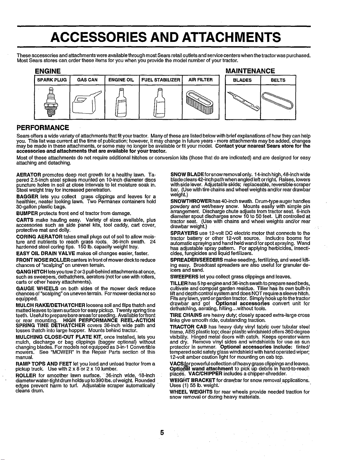
These accessories and attachments wereavailable throughmost Sears retail outlets and service centers when the tractorwas purchased.
Most Sears stores can order these itemsfor you when you provide the model number of your tractor.
ENGINE
SPARK PLUG GAS CAN FUELSTABILIZER AIRFILTERENGINEOIL
MAINTENANCE
BLADES BELTS
PERFORMANCE
Sears offers awide variety of attachments that fit your tractor. Many of these are listed below with brief explanations of how theycan hetp
you. This list was current at the time of publication; however, itmay change infuture years - more attachments may be added, changes
may be made in these attachments, or some may nolonger be available or fit your model. Contact your nearest Sears store for the
accessories and attachments that are available for your tractor,
Most of these attachments do not require additional hitches or conversion kits (those that do are indicated) and are designed for easy
attaching and detaching.
AERATOR promotes deep root growth for a healthy lawn. Ta-
pered 2.5-inch steel spikes mounted on 10-inch diameter discs
puncture holes in soil at close intervals to let moisture soak in.
Steel weight tray for increased penetration,
BAGGER lets you collect grass clippings and leaves for a
healthier, neater looking lawn. Two Permanex containers hold
30-gallon plastic bags.
BUMPER protects front end of tractorfrom damage.
CARTS make hauling easy. Variety of sizes available, plus
accessories such as side panel kits, tool caddy, cart cover,
protective matand doily.
CORING AERATOR takes small plugsout of soilto allow mois-
ture and nutrients to reach grass roots. 36-inch swath. 24
hardened steel coringtips. 150 lb. capacity weight tray.
EASY OIL DRAIN VALVE makes oilchanges easier, faster.
FRONT NOSE ROLLER cantersinfront of mowerdeckto reduce
chances of =scalping" on uneven terrain.
GANG HITCH letsyoutow2 or3 pull-behindattachments atonce,
suchas sweepers, dethatchers, aerators(notfor use withrollers,
carts or other heavy attachments).
GAUGE WHEELS on both sides of the mower deck reduce
chances of"scalping" on uneventerrain. Formower decksnotso
equipped.
MULCH RAKEJDETHATCHER loosenssoiland flipsthatch and
matted leavesto lawn surfacefor easy pickup. Twenty springline
teeth. Usefultopreparebareareasforseeding. Availableforfront
or rear mounting. HIGH PERFORMANCE REEL-ACTION
SPRING TINE DETHATCHER covers 36-inch wide path and
tosses thatch intolarge hopper. Mounts behind tractor.
MULCHING CLOSE-OUT PLATE KIT, once installed, lets you
mulch, discharge or bag clippings (bagger optional) without
changingblades. For models notequippedas 3-in-1 Convertible
mowers. See "MOWER" in the Repair Parts section of this
manual.
RAMP TOPS AND FEET let you Ioad and unloadtractorfrom a
pickuptruck. Use with 2 x 8 or 2 x 10 lumber.
ROLLER for smoother lawn surf.ace. 36:inch wide, .18-inch
diameterwater-tightdrum holdsupto3901bs.ofweight. Rounded.
edges prevent harm to turf. Adjustable scraper automatically
cleans drum.
SNOW BLADEforsnow removalonly. 14-inch high, 48-inch wide
biadeclears 42-inchpathwhen angledleft orright. Raises, lowers
withsidelever. Adjustableskids; replaceable, reversiblescraper
bar. (Usewithtire chainsand wheel weightsand/or rear drawbar
weight.)
SNOWTHROWER has40-inch swath. Drum-type auger handles
powdery and wet/heavy snow. Mounts easily with simple pin
arrangement. Discharge chute adjusts from tractor seat. 6-inch
diameter spout discharges snow 10 to 50 feet. Liftcontrolledat
tractor seat. (Use with chains and wheel weights and/or rear
drawbar weight.)
SPRAYERS use 12-volt DC electric motor that connects to the
tractor battery or other 12-volt source. Includes booms for
automaticspraying and hand heldwand for spot spraying. Wand
has adjustable spraypattern. For applying herbicides, insecti-
cides, fungicides and liquid fertilizers.
SPREADER/SEEDERS make seeding, fertilizing, andweed kiU-
ing easy. Broadcast spreaders are also useful for granular de-
icersand sand.
SWEEPERS letyou collect grass clippingsand leaves.
TILLER has 5hpengine and 36-inch swath toprepare seedbeds,
cultivateand compostgarden residue. Tiller has its own built-in
liftand depthcontrolsystemand does NOT requirea sleeve hitch.
Fitsany lawn,yardorgardentractor. Simply hookup tothetractor
drawbar and go! Optional accessories convert unit for
dethatching,aerating, hilfing...without tools.
TIRE CHAINS are heavy duty; closely spaced extra-large cross
linksgive smooth ride, outstanding traction.
TRACTOR CAB has heavy duty vinyl fabric over tubular steel
frame, ABS plastictop;clear plastic windshieldoffers360 degree
visibility. Hinged metal doors with catch. Keeps operator warm
and dry. Remove vinyl sides and windshields for use as sun
protector in summer. Optional accessories include: tinted/
tempered solid safety glasswindshield with handoperatedwiper;
12-volt amber caution lightfor mounting on cab top.
VACS_r powerfulcollectionofheavy grass clippingsand leaves.
Option) wand attachment to pick up debris in hard-to-reach
pib.€_i. VACtCHIPPER includes a chipper-shredder.
WEIGHT BRACKET for drawbar for snow removal applications.
Uses (t) 55 lb.weight.:
WHEEL WEIGHTS for rear wheeIs provide needed traction for
snowremoval or dozing heavy materials.
5
iiiii iiiiiiiiii , i iiii i ii IH IIIII1"""1 I I IIIII IIIIIIIIIIIII
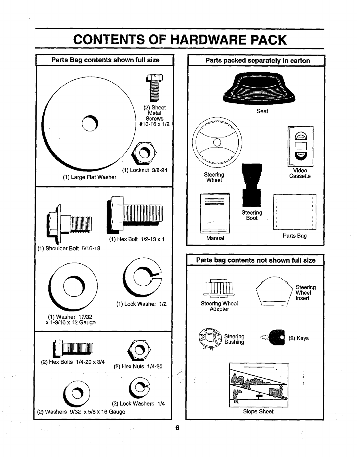
OF HARDWARE PACK
........... ,,ill ,,,,,,,,,,,,,,,,,,,,,,,,,
""'1,
±,, iiiiiii IIIHI IIIIII IIIIIIIIIII
Parts Bag contents shown full size
II I Illllllllll IlllIllllllll Ill
ii1,1,,,,,,i i i i i
i iiiiiii i,11111111 i
Parts packed separately in carton
I IIIIIIIIIIII I IIIIIIII i IIIL
O Screws
(1) Large Flat Washer
(1) Shoulder Bolt 5/16-18
(2) Sheet
Metal
#10-16 x 1/2
(1) Locknut 3/8-24
(1) Hex Bolt 1!2-13 x 1
Seat
Video
Steering
Cassette
Wheel
Steering
Boot
Manual
ii.t iii
Parts bag contents not shown full size
Parts Bag
iJr
I
!
I
|
!
I
"!
I
I
I
(1) LockWasher 1Q/2
(1) Washer 17/32
x 1-3/16 x 12 Gauge
I !fllltltI!1111f1111tlIItI1
(2) Hex Bolts 1/4-20 x 3/4
(2) Hex Nuts 1/4-20
(2) LockWashers 1/4
(2) Washers 9/32 x 5/8 x 16 Gauge
, Wheel
_ Steering
Insert
Steering Whee!
Adapter
_ teering
Bushing
_(2) Keys
Slope Sheet
II
6

LY
i Wl i|l ii
Your new tractor has been assembled at the factory with exception of those parts left unassembted for shipping purposes.
To ensure safe and proper operation of your tractor all parts and hardware you assemble must be tightened securely. Use
the correct tools as necessary to insure proper tightness.
TOOLS REQUIRED FOR ASSEMBLY
A socket wrenchset will make assemblyeasier. Standard
wrench sizes are listed.
(1) 5/16" wrench (1) 3/4" wrench
(2) 7/16" wrenches Tire pressure gauge
(1) 1/2" wrench Utility knife
(1) 9/16" wrench
When right or left hand is mentioned in this manual, it
means when you are in the operating position (seated
behind the steering wheel).
TO REMOVE TRACTOR FROM CARTON
UNPACK CARTON
• Remove att accessible loose parts and parts cartons
from carton (See page 6).
• Cut, from top to bottom, along lines on a]lfour corners
of carton, and lay panels flat.
° Check for any additional loose parts or cartons and
remove.
BEFORE ROLLING TRACTOR OFF SKID
(ASSEMBLY
POSITION)
.__31_EERING WHEELINSERT
_4LOCKNUT
(_LARGEFLAT WASHER
STEERING WHEEL
STEERING
BUSHING
SHEET
TABS
;:Z
METAL
SCREW
ATTACH STEERING WHEEL (See Fig. 1)
• Slide the steering bushing over the steeringshaft.
• Raise steering shaftforward untilscrew holesindash
line up with steering bushing. Install two (2) sheet
metalscrews and tighten securely.
• Positionsteering boot over steeringshaft.
° Place tabs ofsteering boot over tab slotsin dash and
push down to secure.
• Slidesteeringwheel adapter ontouppersteering shaft.
• Positionfront wheels of thetractorsothey are pointing
straightforward.
• Positionsteering wheel so cross bars are horizontal
(leftto right)and slide ontoadapter.
• Assemble large flat washer and 3/8-24 locknut and
tighten securely.
° Snap steering wheel insert into center of steering
wheel.
• Remove protective plasticfrom tractorhood and grill.
IMPORTANT:CHECK FORAND REMOVE ANY STAPLES
IN SKIDTHATMAY PUNCTURE TIRES WHERE TRACTOR
IS TO ROLLOFF SKID.
STEERING SHAFT
(SHIPPING POS_ION)
FIG. 1
TO ROLLTRACTOR OFFSKID (See Operation
section for location and function of controls)
• Pressliftleverplungerand raise attachmentliftleverto
itshighest position.
• Release parking brake by depressing clutch!brake
pedal.
° Place gearshiftlever in neutral (N) position.
• Roll tractorbackwards off skid.
° Remove banding holding discharge guard up against
tractor.
7
ASSEMBLY
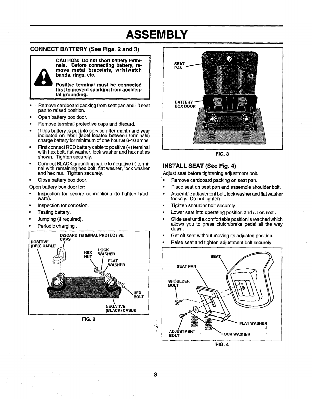
CONNECT BATTERY (See Figs. 2 and 3)
i.ii i. ,,,,,,,,,,,,,,,,,,
CAUTION: Do not short battery termi-
nals. Before connecting battery, re-
move metal bracelets, wristwatch
bands, rings, etc.
Positive terminal must be connected
first to prevent sparking from acciden-
tal grounding.
II IIIIIII ummmmmmm ,
• Remove cardboardpacking from seat pan and lift seat
pan to raised position.
• Open battery box door.
• Remove terminal protective caps and discard.
• if this battery is put into service after month and year
indicated on label (label located between terminals)
chargebattery for minimum of one hour at 6-10 amps.
* First connect RED battery cable to positive(+)terminal
with hex bolt, flat washer, lock washer and hex nut as
shown. Tighten securely.
• Connect BLACK grounding cable to negative (-) termi-
nal with remaining hex bolt, flat washer, lock washer
and hex nut. Tighten securely.
• Close battery box door.
Open battery box door for:
• Inspection for secure connections (to tighten hard-
ware).
• Inspection for corrosion.
• Testing battery.
, Jumping (if required).
• Periodic charging.
DISCARD TERMINAL PROTECTIVE
POSITIVE /
CAPS
SEAT
PAN
BOX DOOR
FIG. 3
INSTALL SEAT (See Fig. 4)
Adjustseat beforetightening adjustmentbolt.
° Remove cardboard packingon seat pan.
• Place seat on seat pan and assembte shoulderbolt.
° Assembleadjustmentbolt,Iockwasherand flatwasher
loosely. Do not tighten.
• Tighten shoulderbolt securely.
• Lower seat intooperating positionand siton seat.
• Slideseat untila comfortablepositionisreachedwhich
altows you to press clutch!brake pedal all the way
down.
• Get offseat withoutmoving itsadjusted position.
• Raise seat and tighten adjustment bolt securety.
HEX WASHER
(RED) CABL_ LOCK
v! WASHER
NUT
FIG. 2
FLAT
NEGATIVE
(BLACK) CABLE
BOLT
8
SEAT
SEAT PAN
SHOULDER
BOLT
FLAT WASHER
ADJUSTMENT
BOLT LOCK WASHER
FIG. 4
ill i ii,,,,,,i | i ,lllllll ,,i,,, i
ASSEMBLY
i H
CHECK TIRE PRESSURE
The tires onyourtractor were overinflated at thefactoryfor
shippingpurposes. Correcttire pressure isimportantfor
best cuttingperformance.
• Reduce tire pressure to PSI shown in "PRODUCT
SPECIFICATIONS" on page 3 of this manual.
CHECK DECK LEVELNESS
For best cuttingresults, mower housing should be properly
leveled. See 'q'O LEVEL MOWER HOUSING" in the
Service and Adjustments section of this manual.
CHECK FOR PROPER POSITION OF ALL
BELTS
See the figures that are shown for replacing motion and
mower blade drive belts in the Service and Adjustments
section of this manual. Verify that the belts are routed
correctly.
CHECK BRAKE SYSTEM
After you learn how to operate your tractor, checkto see
that the brake is properly adjusted. See 'q'O ADJUST
BRAKE" in the Service and Adjustments section of this
manual
v"CHECKLIST
BEFORE YOU OPERATE AND ENJOY YOUR NEW
TRACTOR, WE WISH TOASSURE THAT YOU RECEIVE
THEBEST PERFORMANCEAND SATISFACTION FROM
THIS QUALITY PRODUCT.
PLEASE REVIEW THE FOLLOWING CHECKLIST:
,I All assembly instructionshave been completed.
,f No remainingloose parts in carton.
,f Batteryis properlyprepared and charged. (Minimum
1 hourat 6 amps).
4 Seat isadjustedcomfortably and tightenedsecurely.
,! AIJtires are properlyinflated. (For shippingpurposes,
the tires were overinflated at the factory).
,/ Be sure mower deck is properly leveled side-to-side/
front-to-rear for best cutting results. (Tires must be
properlyinflatedfor leveling).
4 Check mowerand drive belts. Be surethey are routed
properlyaroundpulleys and inside all belt keepers.
,/ Checkwiring. See that all connectionsare stillsecure
and wires are properly clamped.
WH/LELEARNtNG HOW TO USE YOUR TRACTOR, PAY
EXTRA ATTENTION TO THE FOLLOWING IMPORTANT
ITEMS:
/ Engine oil is at proper level.
#" Fuel tank is filled with fresh, clean, regular unleaded
gasoline.
,/ Become familiar with all controls - their Iocation and
function. Operate them before you start the engine.
,# Be sure brake system is in safe operating condition.
9
i, ,,,,,,,,,,,,,,,,,,,,,,,, ,,,,,,,,,,,,,,,,,,,,,,,, ,,,,,,,,,, ...........................................
OPERATION
............ ii, iuuuuuuuuum mllll luuu ml
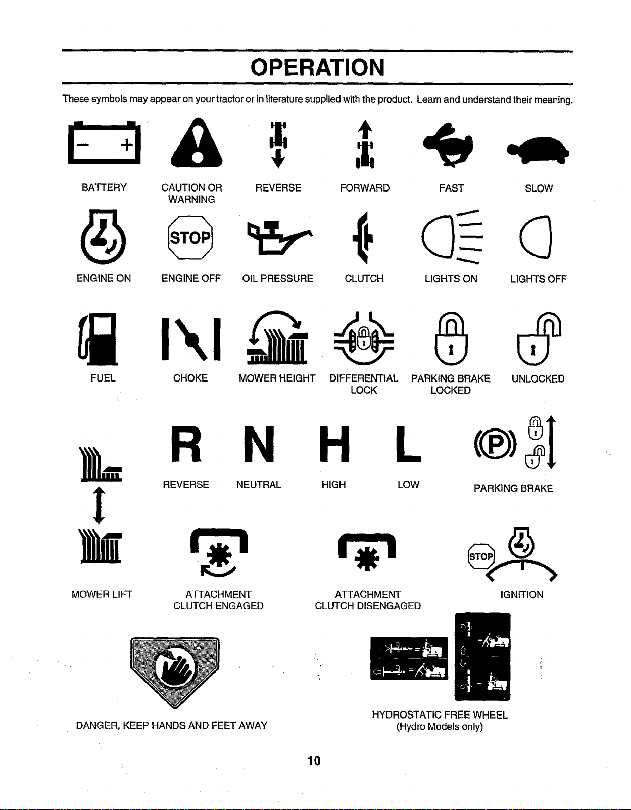
These symbols may appear on your tractororin literature supplied withthe product. Learnand understand their meaning.
A ,
BATTERY CAUTION OR REVERSE FORWARD FAST SLOW
WARNING
ENGINE ON ENGINE OFF OIL PRESSURE CLUTCH LIGHTS ON LIGHTS OFF
FUEL CHOKE MOWER HEIGHT UNLOCKED
DIFFERENTIAL PARKING BRAKE
LOCK LOCKED
R N H L
L
REVERSE NEUTRAL HIGH LOW
PARKING BRAKE
!
MOWER LIFT
ATTACHMENT
CLUTCH ENGAGED
ATTACHMENT
CLUTCH DISENGAGED
IGNITION
DANGER, KEEP HANDS AND FEET AWAY
HYDROSTATIC FREE WHEEL
(Hydro Models only)
10
iill l ,HIIII ii,,ll IIH,,,,,,IIIIIIIIIIlll III1"1 I II I,,lllll HHI I I
OPERATION
i lira ii i i
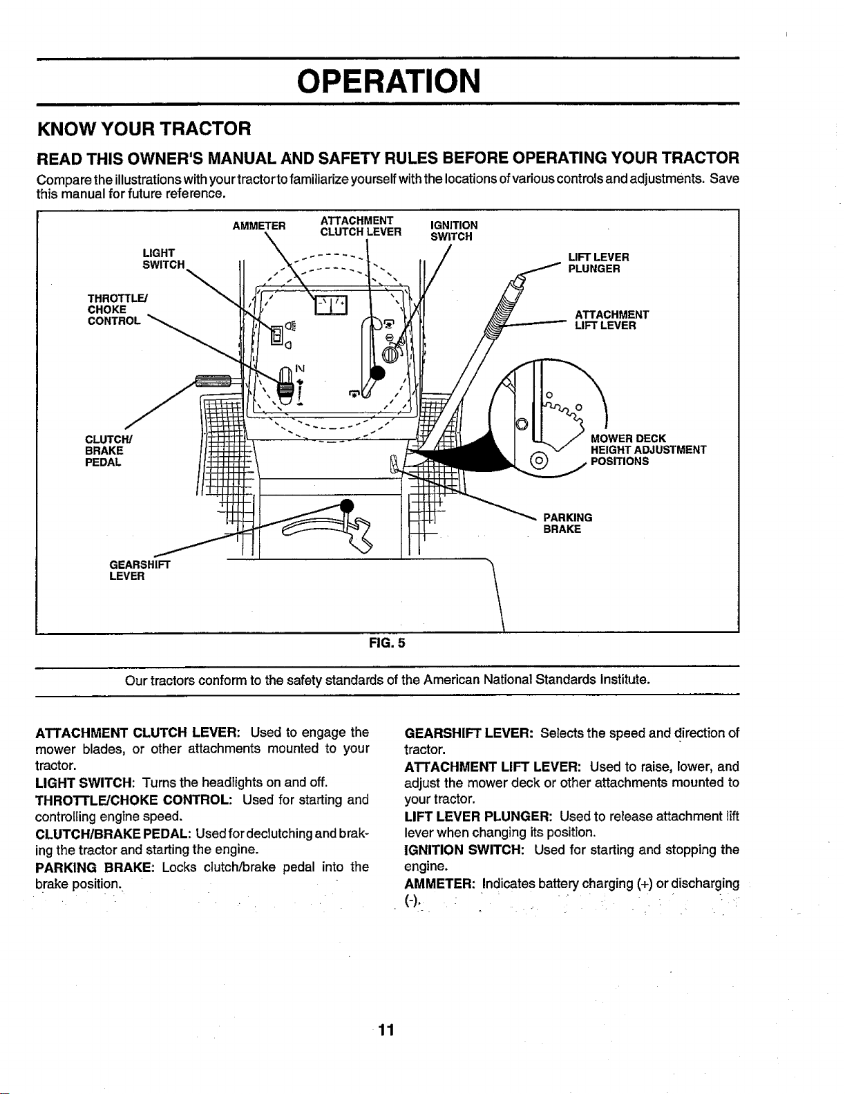
KNOW YOUR TRACTOR
READ THIS OWNER'S MANUAL AND SAFETY RULES BEFORE OPERATING YOUR TRACTOR
Compare the illustrationswithyourtractortofamiliarizeyourselfwiththe locationsofvariouscontrolsand adjustments. Save
this manual for future reference.
THROTTLE/
CHOKE
CONTROL
CLUTCH/
BRAKE
PEDAL
GEARSHIFT
LEVER
AMMETER ATTACHMENT IGNITION
SWITCH
LIGHT 221 UFTLEVER
CLUTCH LEVER SWITCH
MOWER DECK
HEIGHT ADJUSTMENT
POSITIONS
_PARKING
BRAKE
Our tractors conform to the safety standards of the American National Standards Institute.
ATTACHMENT CLUTCH LEVER: Used to engage the
mower blades, or other attachments mounted to your
tractor.
LIGHT SWITCH: Turns the headlightson and off.
THROI-rLE/CHOKE CONTROL: Used for starting and
controllingengine speed.
CLUTCH/BRAKE PEDAL: Usedfordeclutching and brak-
ingthe tractor and starting the engine.
PARKING BRAKE: Locks clutch/brake pedal into the
brake position.,
FIG. 5
GEARSHIFT LEVER: Selects the speed and direction of
tractor.
ATTACHMENT LIFT LEVER: Used to raise, lower, and
adjust the mower deck or other attachments mounted to
yourtractor.
LIFT LEVER PLUNGER: Used to retease attachment lift
lever when changing its position.
IGNITION SWITCH: Used for starting and stopping the
engine.
AMMETER: Indicatesbattery charging (+) or discharging
(-)..... _.
_ , • o, .
11
iii 1,1,,,,,,,i i,i iiiiiiiiiiiiii ii i ,,, ,, ,,,,,,,,,,
RATION
i iiii iiiiii IIII iiiiiiiiiiiiiiiiiiiiiii iii i JIHIIIIIIIIIIIIIII
iiiiiiiiii iiiiiiiiiiiiii iiiiiiiii iiiiiiii iiiiiiiiiiiiiiiiiiiiii IIII iiii iiiiiiiiiiiiiiii i iiiiiiiii ] II
The operation of any tractor can result in foreign objects thrown into the eyes, which
can result in severe eye damage. Always wear safety glasses or eye shields while
operating your tractor or performing anyadjustments orrepairs. We recommend awide
vision safety mask over the spectacles or standard safety glasses.
i,i ........................
HOW TO USE YOUR TRACTOR
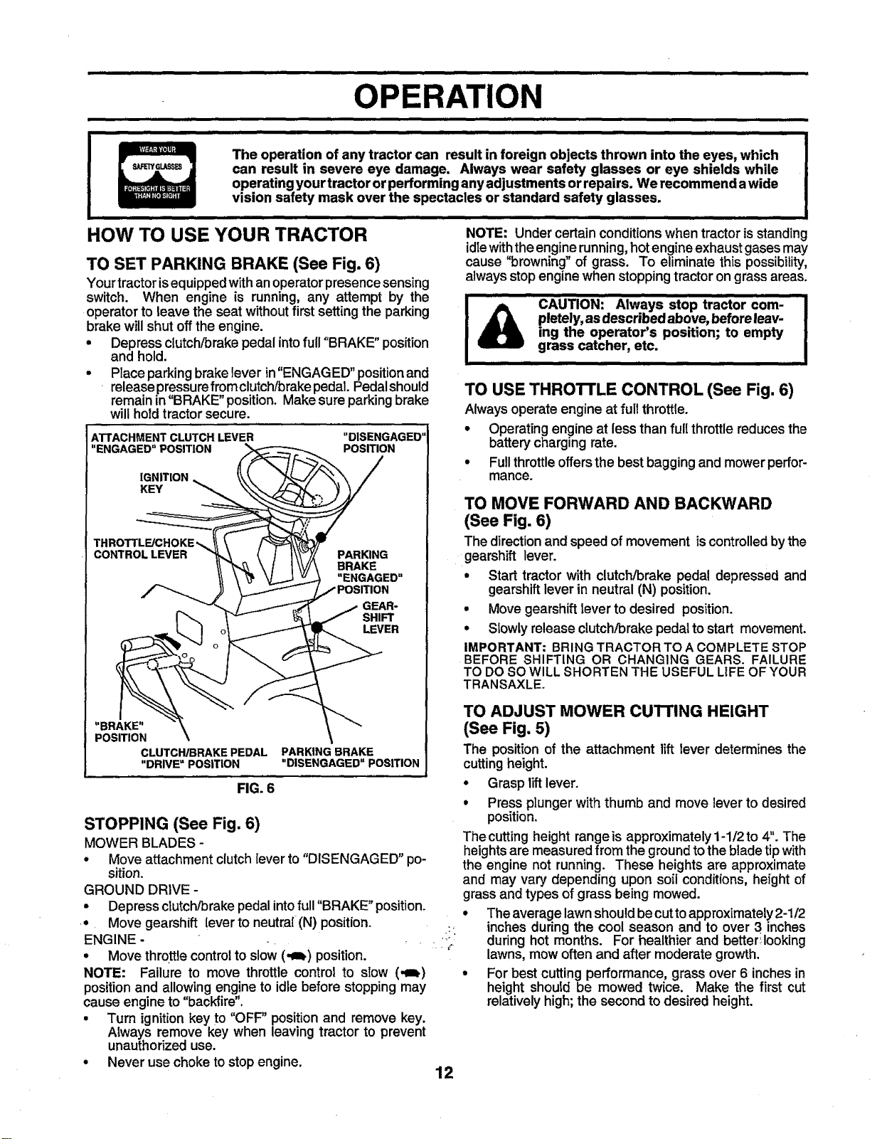
TO SET PARKING BRAKE (See Fig. 6)
Yourtractor is equipped withanoperator presence sensing
switch. When engine is running, any attempt by the
operator to leave the seat without first setting the parking
brake will shut off the engine.
• Depress clutch/brake pedal into full"BRAKE" position
and hold.
• Place parking brake lever in"ENGAGED" position and
release pressure fromclutch/brake pedal. Pedal should
remain in "BRAKE position. Make sure parking brake
will hold tractor secure.
ATTACHMENT CLUTCH LEVER
"ENGAGED" POSITION
IGNITION
KEY
THROTTL_CHOKE_
CONTROLLEVER PARKING
"DISENGAGED"
POSITION
BRAKE
"ENGAGED"
_OSITION
GEAR-
SHIFT
LEVER
NOTE: Under certain conditionswhen tractor is standing
idle with the engine running, hotengine exhaust gases may
cause 'browning of grass. To eliminate this possibility,
always stop engine when stopping tractor on grass areas.
................................CAUTION:Always stop tractor com,
ing the operator's position; to empty
pletely, asdescribed above, before leav-
grass catcher, etc.
TO USE THROTTLE CONTROL (See Fig. 6)
Always operate engine at full throttle.
° Operating engine at less than full throttle reduces the
battery charging rate.
• Fullthrottle offers the best bagging and mower perfor-
mance.
TO MOVE FORWARD AND BACKWARD
(See Fig. 6)
The directionand speed of movement iscontrolledbythe
gearshift lever.
° Start tractor with clutch/brake pedal depressed and
gearshift lever in neutral (N) position.
° Move gearshift lever to desired position.
° Slowly release clutch/brake pedal to start movement.
IMPORTANT: BRING TRACTOR TO A COMPLETE STOP
BEFORE SHIFTING OR CHANGING GEARS. FAILURE
TO DOSO WILL SHORTEN THE USEFUL UFE OF YOUR
TRANSAXLE.
|
"BRAKE" \
POSITION \
CLUTCH/BRAKE PEDAL PARKING BRAKE
"DRIVE = POSITION "DISENGAGED" POSITION
FIG. 6
STOPPING (See Fig. 6)
MOWER BLADES -
° Move attachment clutch lever to "DISENGAGED" po-
sition.
GROUND DRIVE -
• Depress dutch!brake pedal into full "BRAKE" position.
• Move gearshift lever to neutra[ (N) position.
ENGINE - .
° Move throttle control to slow (,gb) position.
NOTE: Failure to move throttle control to slow (-=_)
position and allowing engine to idle before stopping may
cause engine to "backfire".
• Turn ignitionkey to "OFF" position and remove key.
Always remove key when leaving tractor to prevent
unauthorized use.
• Never use choke to stop engine.
TO ADJUST MOWER CUTTING HEIGHT
(See Fig. 5)
The position of the attachment liftlever determines the
cutting height.
° Grasp lift lever.
• Press plunger with thumb and move lever to desired
position.
The cutting height range is approximately 1-1/2 to 4". The
heights are measured from the ground to the blade tip with
the engine not running. These heights are approximate
and may vary depending upon soil conditions, height of
grass and types of grass being mowed.
° The average lawn should becut to approximately 2-1/2
inches during the cool season and to over 3 inches
during hot months. For healthier and better'.looking
lawns, mow often and after moderate growth.
• For best cutting performance, grass over 6 inches in
height should be mowed twice. Make the first cut
relatively high; the second to desired height.
12
iiiiiiiiiiiii HI I
OPERATION
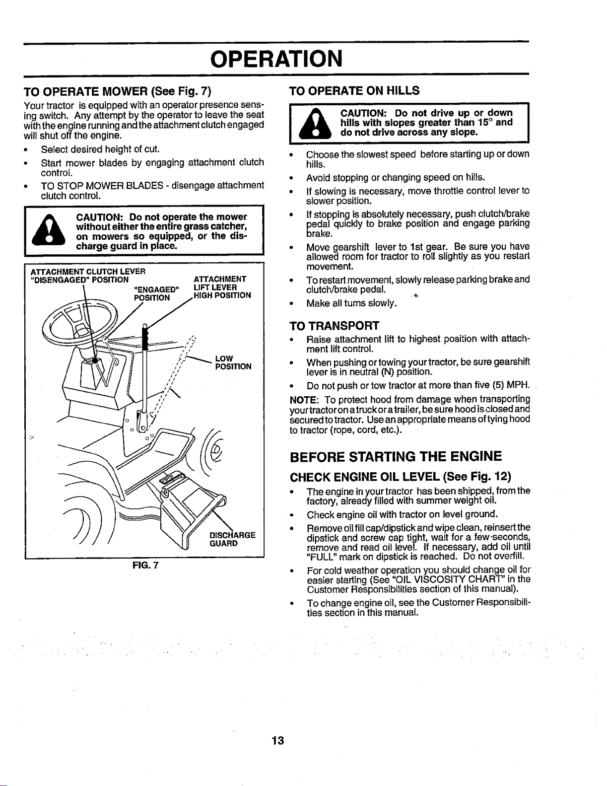
TO OPERATE MOWER (See Fig. 7)
Yourtractor isequipped withan operator presencesens-
ingswitch. Any attempt by the operatorto leave the seat
withtheengine running andtheattachment clutchengaged
will shut off the engine.
• Select desired heightof cut.
• Start mower blades by engaging attachment clutch
control
° TO STOP MOWER BLADES - disengage attachment
clutch control.
i = i ,1
without either the entire grass catcher,
CAUTION: Do not operate the mower
on mowers so equipped, or the dis-
II III III IIIIIIIIIIIIII [ II I
ATTACHMENT CLUTCH LEVER
"DISENGAGED" POSITION
charge guard in place.
"ENGAGED"
POSITION
ATTACHMENT
LIFT LEVER
HIGH POSITION
TO OPERATE ON HILLS
i iiiii i ii IIIII,,,IIIIIIH I II I,I,,HI,I_
hills with slopes greater than 15° and
CAUTION: Do not drive up or down
do not drive across any slope.
II I I Ill I I HI I
• Choose the slowest speed before starting upor down
hills.
° Avoid stopping or changing speed on hilts.
• If slowing is necessary, move throttle control lever to
slower position.
° If stopping is absolutely necessary, push clutch/brake
pedal quickly to brake position and engage parking
brake.
° Move gearshift lever to 1st gear. Be sure you have
allowed room for tractor to roll slightly as you restart
movement.
° To restart movement, slowly release parking brake and
clutch/brake pedal.
• Make all turns slowly.
TO TRANSPORT
• Raise attachment lift to highest positionwith attach-
ment liftcontrol.
° When pushingortowingyourtractor, be sure gearshift
lever is in neutral (N) position.
° Do notpushor tow tractorat more than five (5) MPH.
NOTE: To protecthoodfrom damage when transporting
yourtractoronatruckoratrailer, besurehoodisclosedand
securedtotractor. Use an appropriatemeans oftyinghood
to tractor (rope, cord, etc.).
I
FIG. 7
DISCHARGE
GUARD
BEFORE STARTING THE ENGINE
CHECK ENGINE OIL LEVEL (See Fig. 12)
° The engineinyourtractor hasbeen shipped,fromthe
factory,already filled with summer weight oil.
• Check engine oilwithtractor on level ground.
• Remove oilfillcap!dipstickandwipe clean, reinsertthe
dipstickand screw cap tight, wait for a few-seconds,
remove and read oil lever, if necessary, add oil until
"FULL" markon dipstickis reached. Do not overfill.
• For cold weather operation you should change oilfor
easier starting (See "OIL VISCOSITY CHART" inthe
Customer Responsibilitiessection ofthis manual).
• To change engine oil,see the Customer Responsibili-
ties section inthis manual.
13
ii i i, i ii,,llllllllllllll ii i illll ii, i i ii H I Illl,,I
ATION
ii IIIIIIIIII IIIIIIIIIIIIIIIIII I IIIIIII I I II IIIIIIIIIIIIIIIIIIII IIIIIIIIIIIIIIIIIIIIII i I II I I IIIII I
ADD GASOLINE
° Fill fuel tank. Use fresh, clean, regular unleaded
gasoline with aminimum of 87 octane. (Useof leaded
gasoline will increase carbon and lead oxide deposits
and reduce valve life). Do not mix oil with gasoline.
Purchase fuet in quantities that can be used within 30
days to assure fuel freshness.
IMPORTANT: WHEN OPERATING IN TEMPERATURES
BELOW32°F(0°C), USE FRESH, CLEAN WINTER GRADE
GASOLINE TO HELP INSURE GOOD COLD WEATHER
STARTING.
WARNING: Experience indicates that alcohol blended
fuels (called gasohol or using ethanol or methanol) can
attract moisture which leads to separation andformation of
acids during storage. Acidic gas can damage the fuel
system of an engine while in storage. To avoid engine
problems, the fuel system should be emptied before stor-
age of 30 days or longer. Drain the gas tank, start the
engine and let it run until the fuel lines and carburetor are
empty. Use fresh fuel next season. See Storage Instruc-
tions for additional information. Never use engine or
carburetor cleaner products in the fuel tank or permanent
damage may occur.
i b I IIIII
\
TO START ENGINE (See Fig. 6)
When starting the engine for the first time or if the engine
has run out of fuel, it will take extra cranking time to move
fuel from the tank to the engine.
• Depress clutch/brake pedal and set parking brake.
• Place gear shift lever in neutral (N) position.
• Move attachment clutch to "DISENGAGED" position.
• Move throttle control to choke (_) position.
Note: Before starting, read the warm and cold starting
procedures below.
• Insertkey[ntoignitionandturn keyclockwise to"START"
position and release key as soon as engine starts. Do
not run starter continuously for more than fifteen sec-
onds per minute. If the engine does not start after
several attempts, move throttle control to fast (,_)
position, wait afew minutes andtry again. Ifengine still
does not start, move the throttle control back to the
choke ([\1) position and retry.
WARM WEATHER STARTING (50° F and above)
• When engine starts, movethe throttle control tothe fast
(,_) position.
• The attachments and ground drive can nowbe used. If ;
the engine does not accept the load, restart the engine
and allow itto warm upfor one minute using the choke ; "
as described above.
filler neck. Do not overfill. Wipe off any
spilled oil or fuel. Do not store, spill or
CAUTION: Fill to bottom of gas tank
use gasoline near an open flame.
I HIIII I IIII I III
COLD WEATHER STARTING ( 50° F and below)
• When engine starts, a.llqwengine to run with the throttle
control in the choke ._%,1)position until the engine runs
roughly, then move tl'irdttle control to fast (,_) position.
This may require an engine warm-up period from
several seconds to several minutes, depending on the
temperature.
• The attachments can also be used dudng the engine
warm-up period.
NOTE: if at a high altitude (above 3000 feet) or in cold
temperatures (below 32 F)the carburetor fuel mixture may
need to be adjusted for best engine performance. See 'q'O
ADJUST CARBURETOR" in the Service and Adjustments
section of this manual.
MOWING TIPS
• Tire chainscannotbe used when the mower housing is
attached to tractor.
• Mower should be properly leveled for best mowing
performance. See'q'O LEVEL MOWER HOUSING" in
the Service and Adjustments section of this manual.
• The left hand side of mower should be used for trim-
ming.
• Drive so that clippings are discharged onto the area
that has been cut. Have the cut area to the right of the
machine. This will result in a more even distribution of
clippings and more uniform cutting.
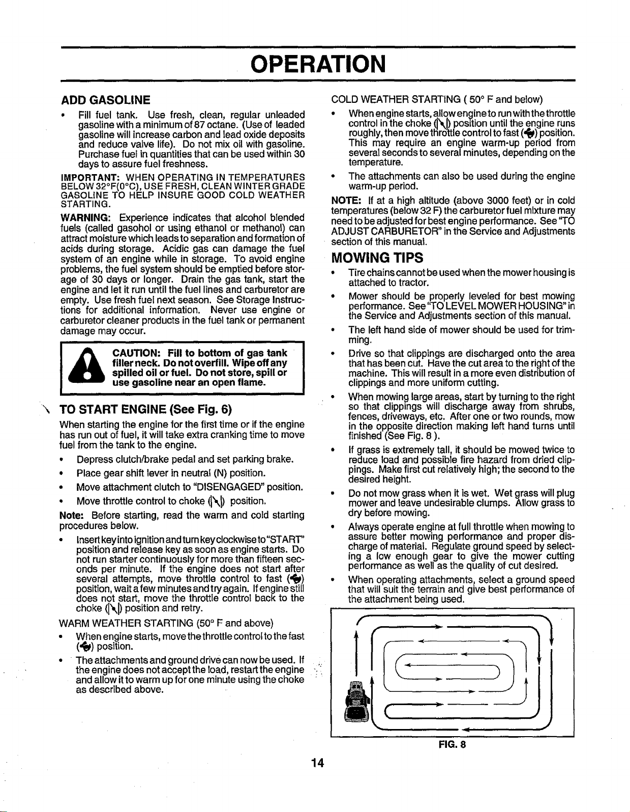
• When mowing large areas, start by turning to the right
so that clippings will discharge away from shrubs,
fences, driveways, etc. After one or two rounds, mow
in the opposite direction making left hand turns until
finished (See Fig. 8 ).
• tf grass is extremely tall, it should be mowed twice to
reduce load and possible fire hazard from dried clip-
pings. Make first cut relatively high; the second to the
desired height.
• Do not mow grass when it is wet. Wet grass will plug
mower and leave undesirable clumps. Allow grass to
dry before mowing.
° Always operate engine at full throttle when mowing to
assure better mowing performance and proper dis-
charge of material. Regulate ground speed by select-
ing a low enough gear to give the mower cutting
performance as well as the quality of cut desired.
• When operating attachments, select a ground speed
that will suit the terrain and give best performance of
the attachment being used.
f
14
(
i ,ll
FIG. 8
CUSTOMER
MAINTENANcElllI "' SCHEDULE'' ""'"' ' '" ..........."....................... J____ If
REGULAR SERV!CE .... /___SERVICE DATES
IBILITIES
CheckTirePressure
CheckforLooseFasteners
C
R Sharpen/ReplaceMowerBtades _64
T CheckBatteryLevel/Recharge
0 CleanBatteryandTerminals
R CheckTransaxTeCooling
AdjustBladeBelt(s)Tension
AdjustMotionDriveBelt(s)Tension
ii i IIIIIIIiiiiiiii
CheckEngineOilLevel
ChangeEngineOil
Clean Air Filter
E .....
N Clean Air Screen
G i Inspect MufflerlSpark Arrester
I ReplaceOilFilter(If equipped)
Fins
ReplaceSparkPlug
ReplaceAirFilterPaperCartridge
ReplaceFuelFilter
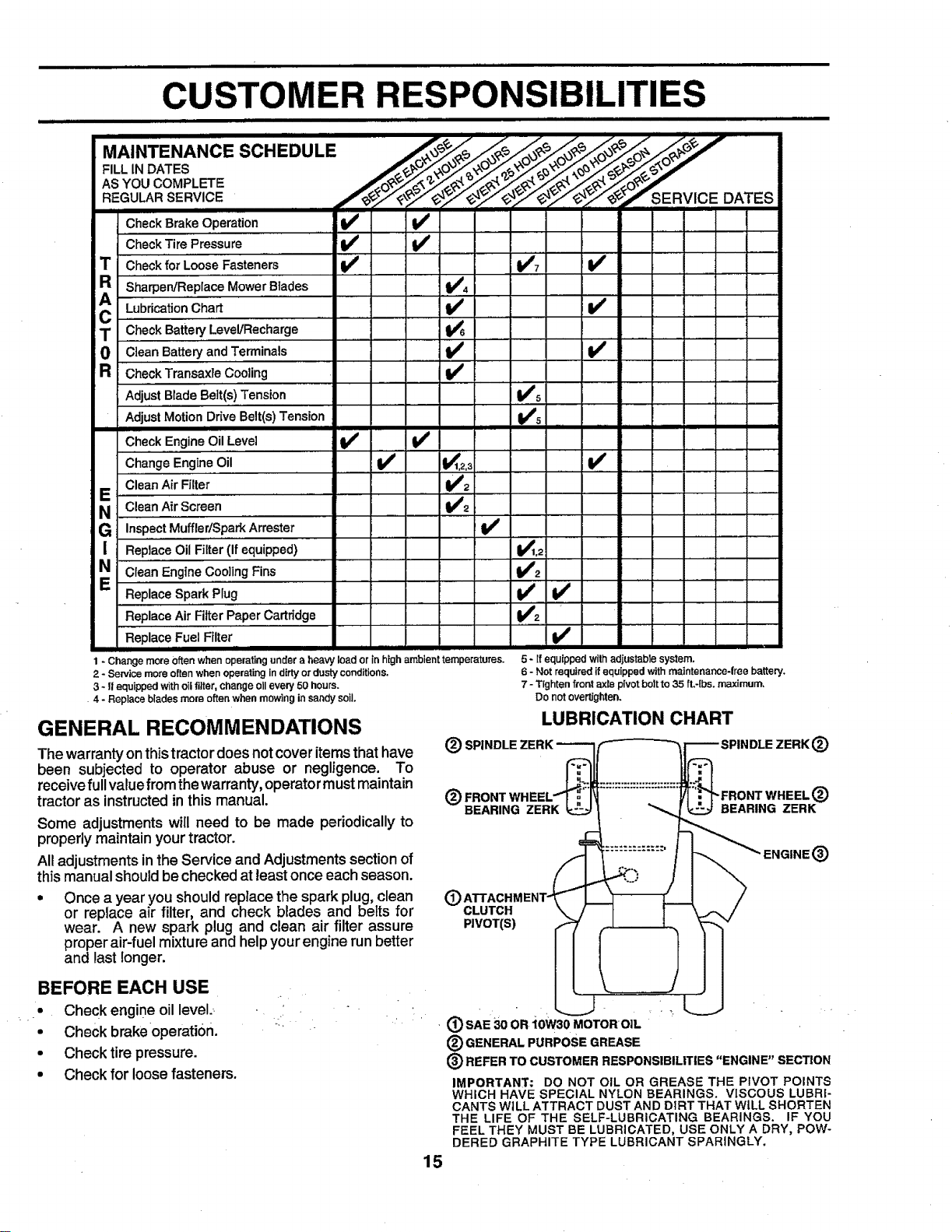
1 - Change more Often when operating under a heavy load or in high ambient temperatures.
2 - Service more often when operating in dirtyordusty conditions.
3 - If equipped with oil tilter, change oilevery 50 hours.
=4 - Replace blades more often when mowing in sandysoil.
......,_,
.......... _1#5
v' v'
V' 1_,21,.......... V'
GENERAL RECOMMENDATIONS
The warrantyon thistractordoes not cover itemsthat have
been subjected to operator abuse or negligence. To
receivefullvaluefrom thewarranty, operatormustmaintain
tractor as instructedin this manual.
Some adjustmentswill need to be made periodically to
properlymaintain your tractor.
All adjustments inthe Service and Adjustmentssectionof
this manualshouldbe checked at least once each season.
• Once a year you should replacethe spark plug,clean
or replace air filter, and check blades and beFtsfor
wear. A new spark plug and clean air filter assure
proper air-fuel mixture and helpyour engine run better
and last longer.
v'
v' v'
v'
ii ii
V'0
V',
v'
v'2
v' v'
V'2
V"
5 * ff equipped withad|ustable system,
6 - Not required if equipped with maintenance*free battery,
7 - Tighten front axle pivot bolt to 35 ft.-lbs, maximum.
Do notovertJghten.
LUBRICATION CHART
(_) SPINDLE ZERK
(_ "FRONT WHEEL (_)
BEARING ZERK BEARING ZERK
®
CLUTCH
PIVOT(S)
®
BEFORE EACH USE
• Check engine oil level
• Check brakeoperati0n.
• Check tire pressure.
• Check for loose fasteners.
• (_) SAE 30 OR "lOW30 MOTORO]L ' " ; "
(_) GENERAL PURPOSE GREASE
(_) REFER TO CUSTOMER RESPONSIBILITIES "ENGINE" SECTION
IMPORTANT: DO NOT OIL OR GREASE THE PIVOT POINTS
WHICH HAVE SPECIAL NYLON BEARINGS. VISCOUS LUBRI-
CANTS WILL ATTRACT DUST AND DIRT THAT WILL SHORTEN
THE LIFE OF THE SELF-LUBRICATING BEARINGS. IF YOU
FEEL THEY MUST BE LUBRICATED, USE ONLY A DRY, POW-
DERED GRAPHITE TYPE LUBRICANT SPARINGLY.
15
iiiii i i ii,,,,,m ii ,,,,, i iiii i iiiiiiiiiii iiiiiiiiii ii
CUSTOMER
TRACTOR
Alwaysobserve safety ruleswhen performingany mainte-
nance.
BRAKE OPERATION
If tractor requires more than six (6) feet stopping distance
at highspeed inhighestgear, thenbrake mustbe adjusted.
(See '_TOADJUST BRAKE" in the Service and Adjust-
ments section ofthismanual).
TIRES .
• Maintain proper air pressure in all tires (See "PROD-
UCT SPECIFICATIONS" on page 3 of this manual).
• Keep tires free of gasoline, oil,or insect control chemi-
cals which can harm rubber.
• Avoid stumps, stones, deep ruts, sharp objects and
other hazards that may cause tire damage.
BLADE CARE
For best results mower blades must be kept sharp. Re-
place bent or damaged blades.
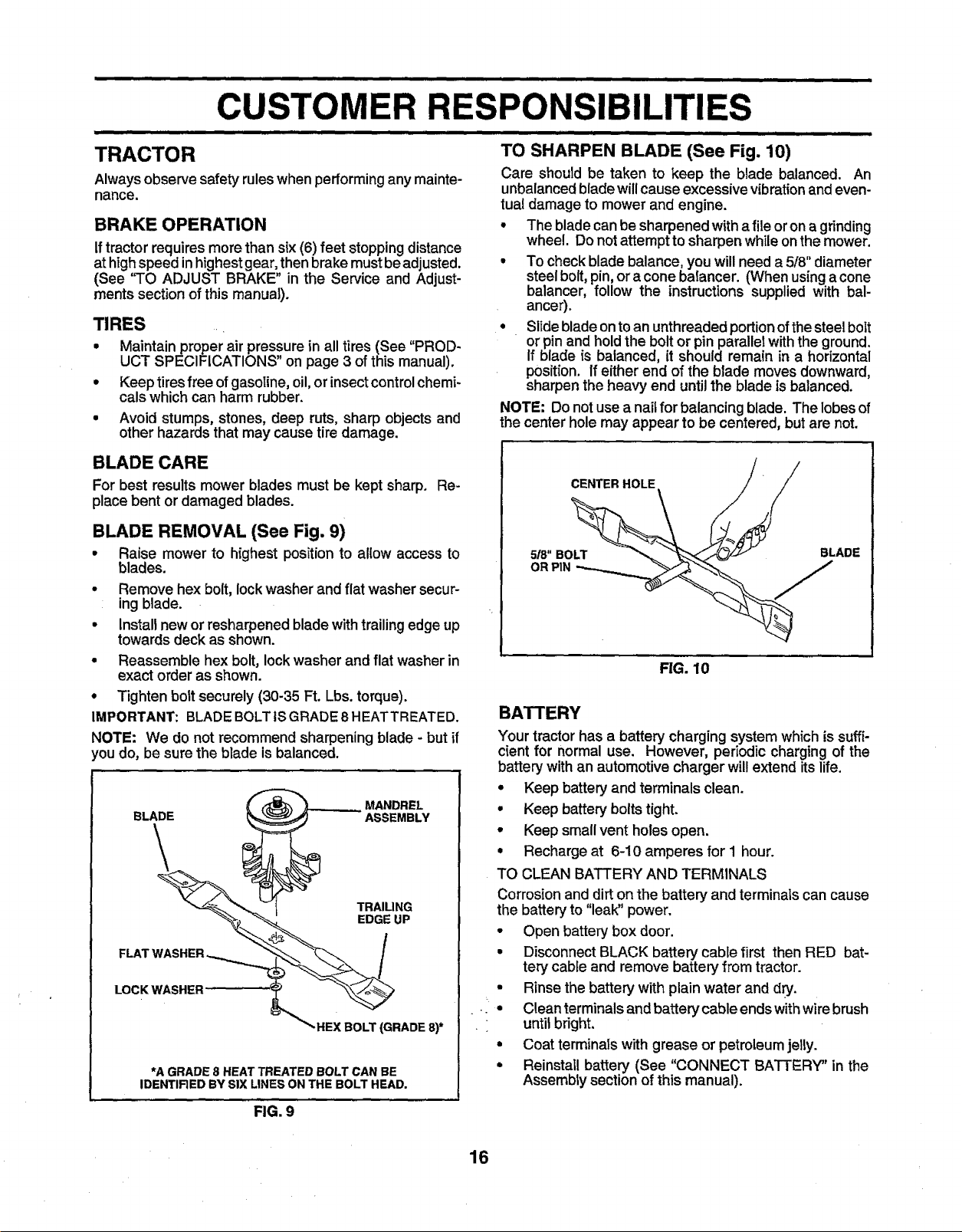
BLADE REMOVAL (See Fig. 9)
• Raise mower to highest position to allow access to
blades.
• Remove hex bolt, lock washer and flat washer secur-
ing blade.
• install new or resharpened blade with trailing edge up
towards deck as shown.
• Reassemble hex bolt, lock washer and flat washer in
exact order as shown.
• Tighten bolt securely (30-35 Ft. Lbs. torque).
IMPORTANT: BLADE BOLTtS GRADE 8 HEATTREATED.
NOTE: We do not recommend sharpening blade - but if
lou do, be sure the blade is balanced.
BLADE ASSEMBLY
MANDREL
\
TRAILING
EDGE UP
FLAT WASHER _ _ /
LOCKWASHER _'__
_'HEX BOLT (GRADE 8)*
*A GRADE 8 HEAT TREATED BOLT CAN BE
IDENTIRED BY SIX LINES ON THE BOLT HEAD.
FIG. 9
SIBILITIES
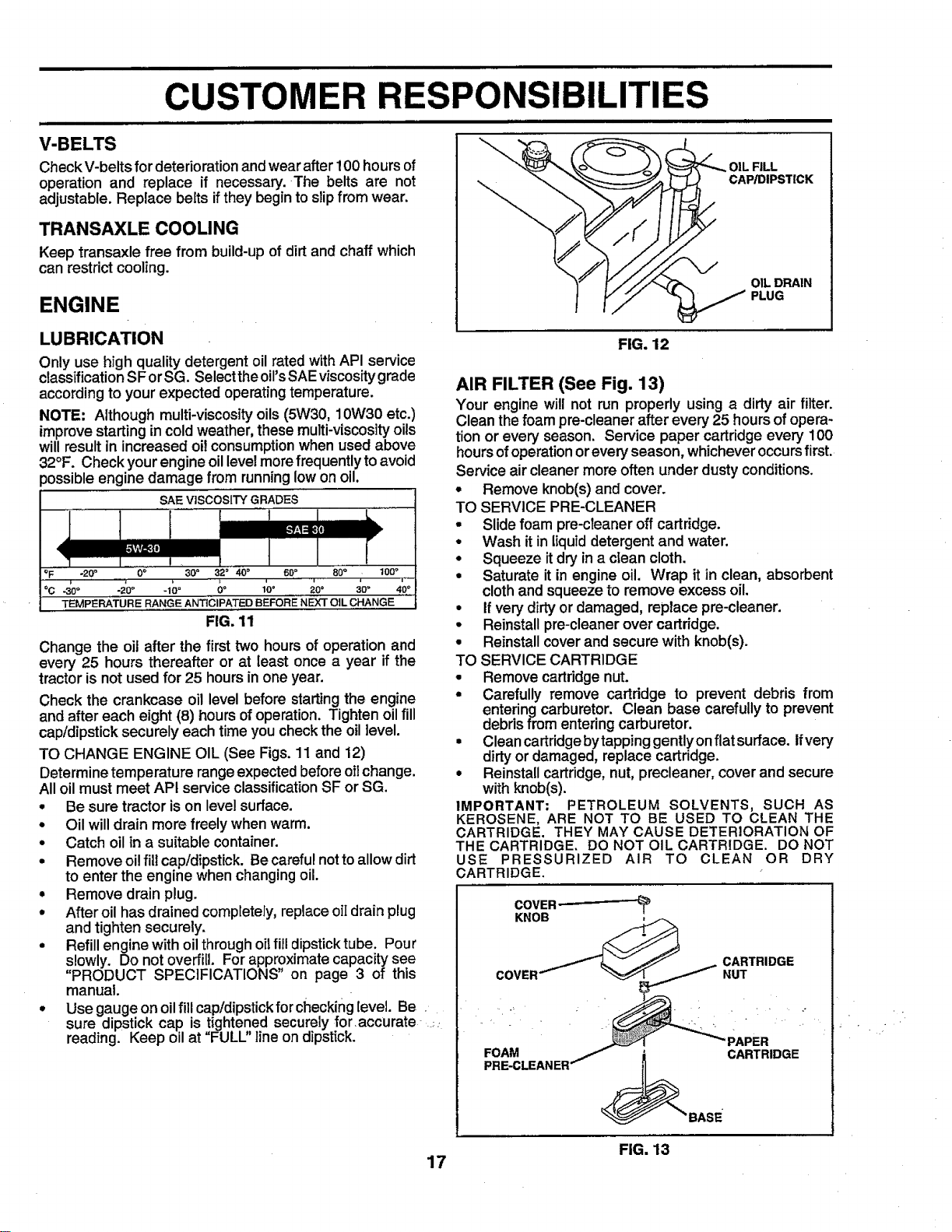
TO SHARPEN BLADE (See Fig. 10)
Care should be taken to keep the blade balanced. An
unbalancedbladewillcause excessive vibrationandeven-
tual damage to mower and engine.
• The bladecan be sharpened with afile oron a grinding
wheel. Donot attempt tosharpen whileonthe mower.
• To check blade balance, you willneed a 5/8" diameter
steelbolt,pin,ora cone balancer. (When usingacone
balancer, follow the instructions supplied with bal-
ancer).
• Slideblade onto an unthreaded portion of thesteel bolt
or pin and hold the bolt or pin parallel with the ground.
If blade is balanced, it should remain in a horizontal
position. If either end of the blade moves downward,
sharpen the heavy end until the blade is balanced.
NOTE: Do not use a nail for balancing blade. The lobes of
the center hole may appear to be centered, but are not.
CENTER HOLE /" /
OR PIN _J
FIG. 10
BATTERY
Your tractor has a battery charging system whichis suffi-
cient for normal use, However, periodic charging of the
battery with an automotivecharger will extend its life.
• Keep battery and terminals clean.
• Keep battery bolts tight.
• Keep small vent holes open.
• Recharge at 6-10 amperes for 1 hour.
TO CLEAN BATTERY AND TERMINALS
Corrosion and dirt on the battery and terminals can cause
the battery to "leak" power.
• Open battery box door.
• DisconnectBLACK battery cabie first then RED bat-
tory cable and remove battery from tractor.
• Rinse the battery with plain water and dry.
• Clean terminals and battery cable ends with wire brush
until bright.
• Coat terminals with grease or petroleum jelly.
• Reinstall battery (See "CONNECT BATTERY" in the
Assembly section of this manual).
16
iiiiiiiiiiiiiiiiii ii iiiiiiiiiiiiiiiiiiii iii ii ii
CUSTOMER RESPONSIBI
V-BELTS
Check V-belts fordeterioration andwear after 100 hours of
operation and replace if necessary. The belts are not
adjustable. Replace belts if they begin to slip from wear.
TRANSAXLE COOLING
Keep transaxle free from build-up of dirt and chaff which
can restrict cooling.
ENGINE
OIL FILL
CAP/DIPSTICK
OIL DRAIN
PLUG
LUBRICATION
Only use high quality detergent oilrated with API service
classificationSF orSG. Selectthe oil'sSAEviscositygrade
accordingto your expected operatingtemperature.
NOTE: Although multi-viscosity oils (5W30, 10W30 etc.)
improvestarting in cold weather, these multi-viscosity oils
will result in increased oil consumption when used above
32°F. Check your engine oil level more frequently to avoid
possible engine damage from running low on oil.
SAE VISCOSITY GRADES
4 i,
oF -20 ° 0_ 30 ° 32 ° 40 ° 60° 80 ° 100o
°c -_o° -_o oo _° soo 3o° 40°
-_0 _ .....
TEMPERATURE RANGE ANTICIPATED BEFORE NEXT OIL CHANGE
FIG. 11
Change the oil after the first two hours of operation and
every 25 hours thereafter or at least once a year if the
tractor is not used for 25 hours in one year.
Check the crankcase oil level before starting the engine
and after each eight (8) hours of operation. Tighten oil fill
cap/dipstick securely each time you check the oil level.
TO CHANGE ENGINE OIL (See Figs. 11 and 12)
Determine temperature range expected before oil change.
All oil must meet API service classification SF or SG.
• Be sure tractor is on level surface.
• Oil will drain more freely when warm.
• Catch oil in a suitable container.
• Remove oil fill cap/dipstick. Be careful not to allow dirt
to enter the engine when changing oil.
• Remove drain plug.
• After oil has drained completely, replace oiI drain plug
and tighten securely.
• Refill engine with oil through oil fill dipstick tube. Pour
slowly. Do not overfill. For approximate capacity see
"PRODUCT SPECIFICATIONS" on page 3 of this
manual.
• Use gauge on oil fill cap/dipstick for checking level. Be
sure dipstick cap is tightened securely for accurate _
reading. Keep oil at "FULU' line on dipstick.
FIG. 12
AIR FILTER (See Fig. 13)
Your engine will not run properly using a dirty air filter.
Cleanthe foampre-cleaner after every 25 hoursof opera-
tion or every season. Service paper cartridge every 100
hoursof operationorevery season, whicheveroccursfirst.
Service air cleaner more often under dusty conditions.
• Remove knob(s) and cover.
TO SERVICE PRE-CLEANER
• Slide foam pre-cTeaneroff cartridge.
• Wash it in liquid detergent and water.
• Squeeze it dry in a clean cloth.
• Saturate it in engine oil. Wrap it in clean, absorbent
cloth and squeeze to remove excess oil.
• If very dirty or damaged, replace pre-cleaner.
• Reinstall pre-cleaner over cartridge.
• Reinstall cover and secure with knob(s).
TO SERVICE CARTRIDGE
• Remove cartridge nut.
• Carefully remove cartridge to prevent debris from
entering carburetor. Clean base carefully to prevent
debris from entering carburetor.
• Clean cartridge by tapping gentlyon flat surface, if very
dirty or damaged, replace cartridge.
• Reinstall cartridge, nut, precleaner, cover and secure
with knob(s).
IMPORTANT: PETROLEUM SOLVENTS, SUCH AS
KEROSENE, ARE NOT TO BE USED TO CLEAN THE
CARTRIDGE. THEY MAY CAUSE DETERIORATION OF
THE CARTRIDGE. DO NOT OIL CARTRIDGE. DO NOT
USE PRESSURIZED AIR TO CLEAN OR DRY
CARTRIDGE.
COVER
KNOB _
FOAM / _ CARTRIDGE
17
PRE-CLEANER _"BASE
FIG. 13
 Loading...