

Craftsman 917259011 Owner’s Manual

CRI F
NUMBER 917.259011 ........_OWNER'S=MANUAL_
° Assembly
° Operation
° Customer Responsibilities
° Service and Adjustments
• Repair Parts
For answers to your questions
about this product, Call:
1-800-659-5917 _
Sears Craftsman Help Line
5 am -5 pro, Mort - Sat
CAUTION: Read and follow all safety rules and instructions before operating this equipment.

Safe Operation Practices for Ride-On Mowers
IMPORTANT: TH IS CUTTING MACHIN E IS CAPABLE OF AM PUTATING HAN DS AND FEET AND TH ROWING OBJ ECTS.
FAILURE TO OBSERVE THE FOLLOWING SAFETY INSTRUCTIONS COULD RESULT IN SERIOUS INJURY OR DEATH.
I. GENERAL OPERATION
• Read, understand,and fol[owal! instructions in the manual
and on the machine before starting.
• Only allow responsible adults, who are familiar with the
instructions, to operate the machine.
• Clear the area of objects such as rocks, toys, wire, etc.,
which could be picked up and thrown by the blade.
• Besure the area is clear of other peoplebefore mowing. Stop
machine if anyone enters the area.
• Never carry passengers.
• Do not mow in reverse unless absolutely necessary. Always
look down and behind before and while backing.
• Be aware of the mower discharge direction and do not point
it at anyone. Do not operate the mower without either the
entire grass catcher or the guard in p[ace.
• Slow down before turning.
• Never leave a running machine unattended. Always turn off
blades, set parking brake, stop engine, and remove keys
before dismounting.
• Turn off blades when not mowing.
• Stop engine before removing grass catcher or unclogging
chute.
• Mow only in daylight or good artificial light.
• Do not operate the machine while under the influence of
alcohol or drugs.
• Watch for traffic when operating near or crossing roadways.
• Use extra care when loading or unloading the machine into
a trailer or truck.
il. SLOPE OPERATION
Slopes are a major factor related to loss-of-control and
tipover accidents, which can result in severe injury ordeath.
All slopes require extra caution. Ifyou cannot back up the
slope or ifyou feel uneasy on it, do not mow it.
DO:
• Mow up and down slopes, not across.
• Remove obstacles such as rocks, tree limbs, etc.
• Watch for holes, ruts, or bumps. Uneven terrain could
overturn the machine. Tallgrass can hide obstacles.
• Useslow speed. Choose a low gearso thatyou will not have
to stop or shift while on the slope.
• Follow the manufacturer's recommendations for wheel
weights or counterweights to improve stability.
• Use extra care with grass catchers or other attachments.
These can change the stability of the machine.
• Keep allmovement on the slopes stow and gradual Do not
make sudden changes in speed or direction.
• Avoid starting or stopping on a slope. If tires lose traction,
disengage the blades and proceed slowly straight down the
slope.
DO NOT:
• Donot turn ons}opes unless necessary, and then, turn slowly
and gradually downhill, if possible.
• Do not mow near drop-offs, ditches, or embankments. The
mower could suddenly turn over [fa wheel is over the edge
of a c[iff or ditch, or if an edge caves in.
• Do not mow on wet grass. Reduced traction could cause
sliding.
• Do not try to stabilize themachine by putting your foot onthe
ground.
• Do not use grass catcher on steep slopes.
SAFETY RULES
IlL CHILDREN
Tragic accidents can occur if the operator is not alert to the
presence of children. Children are often attracted to the
machine and the mowing activity. Never assume that
children will remain where you last saw them.
• Keep children out of the mowing area and under the watchful
care of another responsible adult.
• Be alert and turn machine off if children enter the area.
• Before and when backing, Iook behind and down for small
children.
• Never carry children. They may fall off and be seriously
injured or interfere with safe machine operation.
• Never allow children to operate the machine.
• Use extra care when approaching blind corners, shrubs,
trees, or otherobjects that may obscure vision.
IV. SERVICE
• Useextra careinhandling gasoline and otherfuels. They are
flammable and vapors are explosive.
Use only an approved container.
Never remove gas cap or add fuel with the engine
running. Allow engine to cool before refueling. Do not
smoke.
Never refuel the machine indoors.
Never store the machine or fuel container inside where
there is an open flame, such as a water heater.
• Never run a machine inside a closed area.
• Keep nuts and bolts, especially blade attachment bolts, tight
and keep equipment in good condition.
• Never tamper with safety devices. Check their proper
operation regularly.
• Keep machine free of grass, [eaves, or other debris build-up.
Clean oil or fuel spillage. Allow machine to cool before
storing.
• Stop and inspect the equipment if you strike an object.
Repair, if necessary, before restarting.
• Never make adjustments or repairs with the engine running.
• Grass catcher components are subject to wear, damage, and
deterioration, which could expose moving parts or allow
objects to be thrown. Frequently check components and
replace with manufactu rer's recommended parts, when nec-
essary.
• Mower blades are sharp and can cut. Wrap the blade(s) or
wear gloves, and use extra caution when servicing them.
• Check brake operation frequently. Adjust and service as
required.
r i
The engine exhaust from this product con-
Look for this symbol to point out impor-
tant safety precautions. It means
CAUTION]l! BECOME ALERT!!! YOUR
SAFETY IS INVOLVED.
irl ,r
CAUTION: Always disconnect spark plug
wire and place wire where it cannot contact
spark plug in order to prevent accidental
starting when setting up, transporting,
adjusting or making repairs.
ii
i i nil
A WARNING A
tains chemicals known to the State of Califor-
nia to cause cancer, birth defects, or other
reproductive harm.
2

CONGRATULATIONS on your purchase of a Sears
Tractor. It has been designed, engineered and manufac-
tured to give you the best possible dependability and
performance.
Should you experience any problem you cannot easily
remedy, please contact your nearest Sears Authorized
Service Center/Department Department. We have com-
petent, well-trained technicians and the proper tools to
service or repair this tractor.
Please read and retain this manual. The instructionswill
enable you to assemble and maintain your tractor properly.
Always observe the "SAFETY RULES".
MODEL
NUMBER 917.259011
SERIAL
NUMBER
DATEOFPURCHASE
THE MODELAND SERIAL NUMBERS WILL BE FOUND
ON A PLATE UNDER THE SEAT.
YOUSHOULDRECORDBOTHSERtALNUMBERAND
DATE OF PURCHASE AND KEEP IN A SAFE PLACE
FOR FUTURE REFERENCE.
MAINTENANCE AGREEMENT
A Sears Maintenance Agreement is available on this prod-
uct. Contact your nearest Sears store for details.
CUSTOMER RESPONSIBILITIES
• Read and observe the safety rules.
• Follow a regular schedule in maintaining, caring for and
using your tractor.
• Follow the instructions under "Customer Responsibili-
ties" and "Storage" sections of this owner's manual.
PRODUCT SPECIFICATIONS
HORSEPOWER: 22.5
GASOLINE CAPACITY 3.5 GALLONS
AND TYPE: UNLEADED REGULAR
OIL TYPE (APt-SF/SG): SAE 10W30 (above 32°F)
SAE 5W-30 (below 32°F)
OIL CAPACITY: Wi FILTER: 4.2 PINTS
W!O RLTER: 3.7 PINTS
SPARK PLUG: CHAMPION RC12YC
(GAP: .030")
VALVE CLEARANCE: NOT*ADJUSTABLE
GROUND SPEED (MPH): FORWARD: O- 5.8
REVERSE: 0-2.1
TIRE PRESSURE: FRONT: 14 PSI
REAR: 10 PSI
CHARGING SYSTEM: 15 AMPS @ 3600 RPM
BATTERY: AMP/HR: 35
MIN. CCA: 280
CASE SIZE: U1R
BLADE BOLT TORQUE: 30-35 FT. LBS.
WARNING; This tractor is equipped with an internal
combustion engine and should not be used on or near any
unimproved forest-covered, brush-covered or grass-cov-
ered land unless theengine's exhaust system is equipped
with a spark arrester meeting appticable local or state laws
(if any). Ifaspark arrestor is used, itshouEdbe maintained
in effective working order by the operator.
In the state of California the above is required by law
(Section 4442 of the California Public Resources Code).
Other states may have similar laws. Federal laws apply on
federal lands. A spark arrestor for the muffler is available
through your nearest Sears Authorized Service Center/
Department (See REPAIR PARTS section ofthis manual).
LIMITED TWO YEAR WARRANTY ON CRAFTSMAN RIDING EQUIPMENT
For two (2) years from the date of purchase, if this Craftsman Riding Equipment is maintained, lubricated and tuned up according
to the instructionsin the owner's manual, Sears will repair or replace, free of charge, any parts found to be defective in material
or workmanship.
This Warranty does not cover:
• Expendable items which become worn during normal use, such as blades, spark plugs, air cleaners, belts, etc.
• T_rereplacement or repair caused by punctures from outside objects, such as nails, thorns, stumps, or glass.
• Repairs necessary because of operator abuse, negligence, improperstorage or accident at the failure to maintain the
equipment according to the instructionscontained in the owner's manual.
• Riding equipment used for commercial or rental purposes.
LIMITED 90 DAY WARRANTY ON BATTERY
For ninety (90) days from date of purchase, if any battery included with this riding equipment proves detective in material or
workmanship and our testing determines the battery will not hold a charge, Sears will replace the battery at no charge.
IN-HOME WARRANTY SERVICE ON YOUR CRAFTSMAN RIDING EQUIPMENT IS AVAILABLE AT NO-CHARGE FOR 30
DAYS FROM THE DATE OF PURCHASE. PLEASE CONTACT YOUR NEAREST SERVICE CENTER. AFTER 30 DAYS
FROM THE DATE OF PURCHASE, WARRANTY SERVICE IS AVAILABLE BY TAKING YOUR CRAFTSMAN RIDING EQUIP-
MENT TO YOUR NEAREST SEARS SERVICE CENTER. (IN-HOME WARRANTY SERVICE WILL STILL BE AVAILABLE
AFTER 30 DAYS FROM THE DATE OF PURCHASE BUT A STANDARD TRIP CHARGE WILL APPLY.) THiS WARRANTY
APPLIES ONLY WHILE THIS PRODUCT IS IN THE UNITED STATES.
This Warranty gives you specific Iegal rights, and you may also have other rights which may vary from state to state.
SEARS, ROEBUCK AND CO., D/817 WA, HOFFMAN ESTATES, IL 60179
k
3

i|lni=l ii ill
TABLE OF CONTENTS
SAFETY RULES ............................................................ 2
PRODUCT SPEC|FICAT|O NS ...................................... 3
CUSTOMER RESPONSIBILITIES ..................... 3, 17-20
WARRANTY .................................................................. 3
TRACTOR ACCESSORIES ..................................... 5,15
ASSEMBLY .............................................................. 7-10
OPERATION ........................................................... 11-16
=
MAINTENANCE SCHEDULE ...................................... 17
SERVICE AND ADJUSTMENTS ............................ 21-27
STORAGE ................................................................... 28
TROUBLESHOOTING ............................................ 29-30
REPAIR PARTS - TRACTOR ................................. 32-50
REPAIR PARTS - ENGINE .................................... 51-58
PARTS ORDERING/SERVICE ................ BACK COVER
INDEX
A
Accessories ........................................... 5
Adjustments:
Brake ............................................ 23
Carburetor .................................... 27
Clutch Pulley ................................ 23
Gauge Wheels ............................. 14
Mower
Front-To-Back ......................... 22
Side-To-Side ........................... 21
Throttle Control Cable .................. 27
Air Filter, Engine .................................. 20
Air Screen, Engine .............................. 19
Assembly .......................................... 7-10
B
Battery:
Charging ........................................ 8
Cleaning ....................................... 20
Starting with Weak Battery ........... 25
Storage ........................................ 28
Terminals ..................................... 19
Belt:
Motion Drive
Removal/Replacement ............ 24
Mower Drive
Removal/Replacement ............ 22
Mower Blade Drive
Removal/Replacement ............ 23
Blade:
Sharpening ................................... 18
Replacement ................................ 18
Brake Adjustment ................................ 23
C
Carburetor Adjustment ........................ 27
Clutch Pulley ....................................... 23
Controls, Tractor ................................. 12
Customer Responsibilities .............. 17-20
Engine:
Air Filter .................................... 20
Air Screen ................................ 19
Cooling Fins ............................. 20
Engine Oil ........................... 15,19
Fuel Filter ................................. 20
Spark Plug(s) ........................... 20
Tractor:
Battery ...................................... 18
Blade ........................................ 18
Lubrication Chart ...................... 17
Maintenance Schedule ............ 17
Tire Care .......................... 8,18,25
Transaxle ................................. 19
Cutting Height, Mower ......................... 13
E
EJectrical:
fntedocks and Relays .................. 26
Schematic .................................... 31
Wiring Diagram ............................ 32
Engine:
Air Filter........................................ 20
Air Screen .................................... 19
Cooling Fins ................................. 20
Oil Change ................................... 19
Oil Level....................................... 15
Oil Type................................... 15,19
Preparation .................................. 15
Repair Parts ............................ 51-58
Starting ......................................... 15
Storage ........................................ 28
F
FiJter:
Air Filter ........................................ 20
Fuel .............................................. 20
Oil ................................................. 20
Fuel:
Storage ........................................ 28
Type ............................................. 15
Fuse .................................................... 26
H
Headlights ........................................... 26
Hood Removal/Installation .................. 26
L
Leveling Mower Deck .......................... 22
Lubrication:
Chart ........................................... 17
Engine .......................................... I9
M
Maintenance Schedule ....................... 17
Mower:
Adjustment, Front-to-Back ........... 22
Adjustment, Side-to-Side ............. 21
Blade Replacement ...................... 18
Blade Sharpening ........................ 18
Cutting Height .............................. 13
Installation .................................... 21
Operation ..................................... 14
Removal ....................................... 21
Mowing Tips ........................................ 16
Muffler ................................................. 20
Spark Arrester ........................... 3,40
O
Oil:
Cold Weather Conditions ........ 15,19
Engine .......................................... 19
Storage ........................................ 28
4
Operation t 1-16
Operating Mower ................................ 14
Options:
Accessories .................................... 5
Spark Arrester ........................... 3,40
P
Parking Brake ...................................... 13
Parts Bag .............................................. 6
Parts, Replacement/Repair ............ 32-50
Product Specifications ........................... 3
R
Repair Parts ................................... 32-50
S
Safety Rules .......................................... 2
Seat ....................................................... 8
Service and Adjustments ............... 21-27
Carburetor .................................... 27
Clutch Pulley ................................ 23
Fuse ............................................. 26
Hood Removal/Installation ........... 26
Motion Drive Belt
Removal/Replacement ............ 22
Mower Drive Belt
Removal/Replacement ............ 22
Mower Blade Drive Belt
Removal/Replacement ............ 23
Mower Adjustment
Front-to-Back .......................... 22
Side-to-Side ............................ 21
Mower Removal/Installation ......... 21
Tire Care .............................. 8,t6,25
Slope Guide Sheet .............................. 59
Spark Plug(s) ...................................... 20
Specifications ........................................ 3
Starting the Engine ............................. 15
Steering Wheel ................................ 7,24
Stopping the Tractor ........................... 13
Storage ................................................ 28
T
Throttle Control Cable Adjustment ...... 26
Tires............................................ 8,18,25
Troubleshooting Chart ................... 29-30
Transaxle ............................................ 19
W
Warranty ................................................ 3
Wiring Diagram ................................... 32
Wiring Schematic ................................ 31
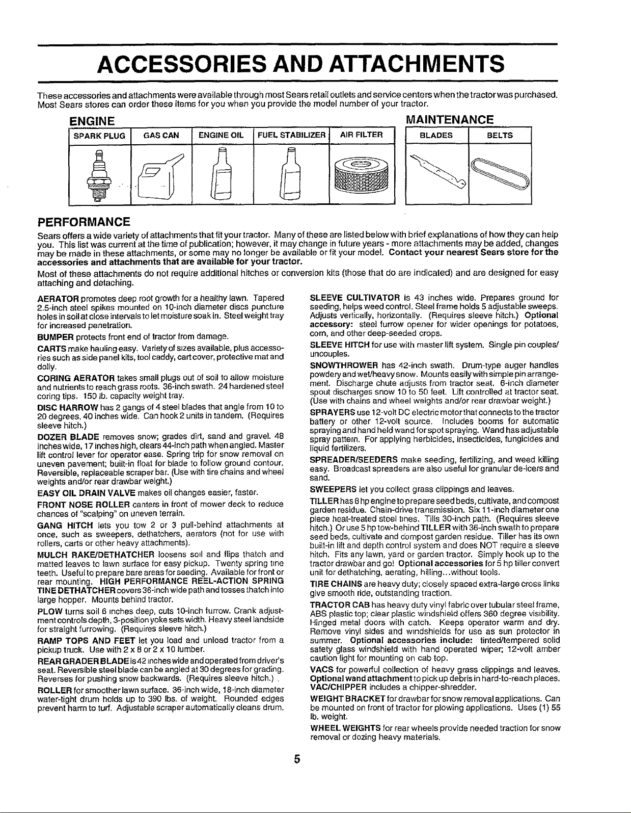
ACCESSORIES AND ATTACHMENTS
These accessories and attachments were available through most Sears retail outletsand service centers when the tractor was purchased.
Most Sears stores can order these items for you when you provide the model number of your tractor.
ENGINE
SPARK PLUG
GAS CAN ENGINE OIL FUEL STABILIZER
AIR FILTER
PERFORMANCE
Sears offers a wide variety of attachments that fit your tractor. Many ofthese are listed below with brief explanations of how they can help
you. This Fistwas current at the time of publication; however, it may change in future years - more attachments may be added, changes
may be made in these attachments, or some may no longer be available or fit your model. Contact your nearest Sears store for the
accessories and attachments that are available for your tractor.
Most of these attachments do not require additional hitches or conversion kits (those that do are indicated) and are designed for easy
attaching and detaching.
AERATOR promotes deep root growth for a healthy lawn. Tapered
2.5-inch steel spikes mounted on 10-inch diameter discs puncture
holes insoil at close intervals to let moistu re soak in. Steel weight tray
for increased penetration,
BUMPER protects front end of tractor from damage.
CARTS make hauling easy. Variety of sizes available, plus accesso-
ries such as side panel kits, tool caddy, cart cove r, protective mat and
dolly.
CORING AERATOR takes small plugs out of soil to allow moisture
and nutdentsto reach grass roots. 36°inch swath. 24 hardened steel
coring tips. 150 lb. capacity weight tray.
DISC HARROW has 2 gangs of 4 steel blades that angle from 10 to
20 degrees, 40 inches wide. Can hook 2 units in tandem. (Requires
sleeve hitch.)
DOZER BLADE removes snow; grades dirt, sand and gravel. 48
inches wide, 17 inches high, clears 44-inch path when angled, Master
lift control lever for operator ease. Spring trip for snow removal on
uneven pavement; buitt-in float for blade to follow ground contour.
Reversible, replaceable scraper bar. (Use with tire chains and wheet
weights and/or rear drawbar weight.)
EASY OIL DRAIN VALVE makes oil changes easier, faster.
FRONT NOSE ROLLER canters in front of mower deck to reduce
chances of "scalping" on uneven terrain.
GANG HITCH lets you tow 2 or 3 pull-behind attachments at
once, such as sweepers, dett_atchers, aerators (not for use with
rollers, carts or other heavy attachments).
MULCH RAKF_JDETHATCHER loosens soil and flips thatch and
matted leaves to lawn surface for easy pickup. Twenty spring t=ne
teeth. Useful to prepare bare areas for seeding. Available for front or
rear mounting. HIGH PERFORMANCE REEL-ACTION SPRING
TINE DETHATCH ER covers 36-inch wide path and tosses thatch into
large hopper. Mounts behind tractor.
PLOW turns soil 6 inches deep, cuts 10-inch furrow. Crank adjust-
ment controls depth, 3-position yoke sets width. Heavy steel landside
for straight furrowing. (Requires sleeve hitch.)
RAMP TOPS AND FEET let you load and unload tractor from a
pickup truck. Use with 2 x 8 or 2x 10 lumber.
REAR GRADER BLADE is42 inches wide and operated from driver's
seat. Reversible steel blade can be angled at 30 degrees for grading.
Reverses for pushing snow backwards. (Requires sleeve hitch.) .
ROLLER for smoother lawn surface. 36-inch wide, 18-inch diameter
water-tight drum holds up to 390 Ibs. of weight. Rounded edges
prevent harm to turf. Adjustable scraper automatically cleans drum.
SLEEVE CULTIVATOR is 43 inches wide. Prepares ground for
seeding, helps weed control. Steel frame holds 5 adjustable sweeps.
Adjusts vertically, horizontally. (Requires sleeve hitch.) Optional
accessory: steel furrow opener for wider openings for potatoes,
corn, and ether deep-seeded crops.
SLEEVE HITCH for use with master lift system. Single pin couples/
uncouples.
SNOWTHROWER has 42-inch swath. Drum-type auger handles
powdery and wet/heavy snow. Mounts easilywith simpJe pin arrange-
ment. Discharge chute adjusts from tractor seat, 6-inch diameter
spout discharges snow 10 to 50 feet. Lift controlled at tractor seat.
(Use with chains and wheel weights and!or rear drawbar weight.)
SPRAYERS use t 2-volt DC electric motor that connects to the tractor
battery or other 12-volt source. Includes booms for automatic
spraying and hand held wand for spot spraying. Wand has adjustable
spray pattern. For applying herbicides, insecticides, fungicides and
liquid fertilizers.
SPREADER/SEEDERS make seeding, fertilizing, and weed killing
easy. Broadcast spreaders are also useful for granular de-icers and
sand.
SWEEPERS tet you collect grass clippings and leaves.
TILLER has 8hp engine to prepare seed beds, cultivate, and compost
garden residue. Chain-drive transmission. Six 11-inch diameterone
piece heat-treated steel tines. Tills 30-inch path. (Requires sleeve
hitch.) Or use 5 hp tow-behind TILLER with 36-inch swath to prepare
seed beds, cultivate and compost garden residue. Tiller has its own
built-in lift and depth control system and does NOT require a sleeve
hitch, Fits any lawn, yard or garden tractor. Simply hook up to the
tractor drawbar and go! Optional accessories for 5 hp tiller convert
unit for dethatching, aerating, hilling...without toots.
TIRE CHAINS are heavy duty; closely spaced extra-large cross links
give smooth ride, outstanding traction.
TRACTOR CAB has heavy duty vinyl fabric over tubuJar steeJ frame,
ABS plastic top; clear plastic windshield offers 360 degree vis=bility.
Hinged metal doors with catch. Keeps operator warm and dry.
Remove vinyl sides and windshields for use as sun protector in
summer. Optional accessories include: tinted/tempered solid
safety glass windshield with hand operated wiper; 12-volt amber
caution light for mounting on cab top.
VACS for powerful collection of heavy grass clippings and leaves.
Optional wand attachment to pick up debris in hard-to-reach places.
VAC/CH[PPER includes a chipper-shredder.
WEIGHT BRACKET for drawbar for snow removal applications. Can
be mounted on front of tractor for plowing applications. Uses (1) 55
Ib, weight.
WHEEL WEIGHTS for rear wheels provide needed traction for snow
removal or dozing heavy materials.
MAINTENANCE
BLADES BELTS
5

i i ill || i
ii |
CONTENTS OF HARDWARE PACK
ii i
III IIIII
(4) Shoulder Bolt _ (12) Crownlock Nuts (4) Wheels/_ (4) Bracke_--_
I(t--_--_ _t,._]IJ3t16x8 (12) Carriage Bolts ((i/_;)) __
i/_i 5116-18 x 518 "_-_ IIIII 1 /
-t..(.-_..) ) (4)o!evisPins --l lllloJ (
• 4,"Ltcknui _'-_/14 Washers i(_ II _-___qJ_ J Nil
_i//_#_-] b 3/8 x _1)4x 14 Ga. : I "j # _
Parts Bag contents
I (4) Retainer Springs It !
I (double loop) ill
I (4) Adjusting Bar [J_J
i
(1) Shoulder Bolt
5/16-18
O
(1) Washer 17/32 x 1-3/16 x 12 Gauge
i ii |
Springs (double loop)
I
aier Springs (single loop)
(1) Knob
Parts packed separately in carton
Steering
Seat
Manual Cassette
Sleeve
Video
Steering
I
i
i
i
i
i i
I
i
Parts Bag
i=
Wheel
Parts bag contents not shown full size
!!_ )ililiill "l_
(2) Front Link Assemblies
(4) Retainer Springs
(2) Hex Bolts 1/4-20 x 3/4
(2) Washers
9/32 x 5/8 x 16 Ga.
(4) Clevis Pins
(2) Hex Nuts
1/4-20
(2) Lock
ihers 1/4
__./)_ Steering _€
Insert
Wheel
(2) Keys
Slope Sheet
6

i |111 • i|11
ASSEMBLY
Your new tractor has been assembled at the factory with the exception ofthose parts left unassembled for shipping purposes.
To ensure safe and proper operation of your tractor all parts and hardware you assemble must be tightened securely. Use
the correct tools as necessary to insure proper tightness.
TOOLS REQUIRED FOR ASSEMBLY
A socket wrench set will make assembly easier. Standard
wrench sizes are listed.
(2) 7/16" wrenches Tire pressure gauge
(1) 1/2" wrench Utility knife
(1) 9/16" wrench PNers
(1) 3/4" socket with drive ratchet
When right or left hand is mentioned in this manual, it
means when you are in the operating position (seated
behind the steering wheel).
TO REMOVE TRACTOR FROM CAR-
TON
STEERING WHEEL INSERT
I' ' RGE FLAT
WASHER
STEERING
WHEEL
E"
UNPACK CARTON
• Remove all accessible loose parts and parts cartons
from carton (See page 6).
• Cut, from top to bottom, along lines on all four corners
of carton, and lay panels flat.
• Check for any additional loose parts or cartons and
remove.
• Remove mower and packing materials.
BEFORE ROLLING TRACTOR OFF SKID
ATTACH STEERING WHEEL (See Fig, 1)
• Remove hex bolt, lock washer and large flat washer
from steering shaft.
• Position front wheels of the tractor so they are pointing
straight forward.
• Slide steering sleeve over steering shaft.
• Position steering wheel so cross bars are horizontal
(left to right) and slide onto steering wheel adapter.
• Secure steering wheel tosteering shaft with hex bolt,
lockwasher and largeflat washer previously removed.
Tighten securely.
• Snap steering wheel insert into center of steering
wheel.
• Remove protective materials from tractor hood and
grill.
IMPORTANT: CHECK FORAND REMOVEANY STAPLES
IN SKiDTHAT MAY PUNCTURETIRES WHERE TRACTOR
_°I_Jr.PF_I<._CTOR OFF SKID (See
Operation section for location and
function of controls)
• Press lift lever plunger and raise attachment lift lever to
its highest position.
• Release parking brake by depressing clutch!brake
pedal.
• Place freewheel control in freewheeling position to
disengage transmission (See 'q-O TRANSPORT" in
the Operation section of this manual).
• Roll tractor backwards off skid.
STEERING STEERING
ADAPTER
WHEE" ///// SHAFT
I / / ._ ...I _"
STEERING / s / / 1
SLEEVE 7 _. , i /
y ! _l i / i
FIG, 1
CONNECT BATTERY (See Fig. 2)
CAUTION: Do not short battery termi-
nals by allowing a wrench or any other
object to contact both terminals at the
same time. Before connecting battery,
remove metal bracelets, wristwatch
bands, rings, etc.
Positive terminal must be connected
first to prevent sparking from acciden-
tal grounding.
• LEfthood to raised position.
• Open terminal access doors, remove terminal protec-
tive caps and discard.
• If this battery is put into service after month and year
indicated on label (label located between terminals)
charge battery for minimum of one hour at 6-I0 amps.
• First connect RED battery cable to positive (+) battery
terminal with hexbolt, flat washer, lock washer and hex
nut as shown. Tighten securely.
• Connect BLACK grounding cable to negative (-) bat-
tery terminal with remaining hex bolt, flat washer, lock
washer and hex nut. Tighten securely.
• Close terminal access doors.
7
i i in iiiii
ASSEMBLY
= |
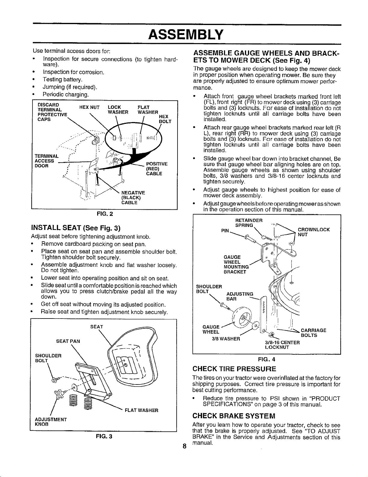
Use terminal access doors for:
• Inspection for secure connections (to tighten hard-
ware).
• Inspection for corrosion.
• Testing battery.
• Jumping (if required).
• Periodic charging.
DISCARD
TERMINAL WASHER WASHER
PROTECTIVE HEX
CAPS BOLT
TERMINAL
ACCESS
DOOR
HEX NUT LOCK FLAT
NEGATIVE
(BLACK)
CABLE
FIG. 2
POSITIVE
(RED)
CABLE
ASSEMBLE GAUGE WHEELS AND BRACK-
ETS TO MOWER DECK (See Fig. 4)
The gauge wheels are designed to keep the mower deck
in proper position when operating mower. Be sure they
are properly adjusted to ensure optimum mower perfor=
mance.
Attach front gauge wheel brackets marked front left
(FL), front right (FR) to mower deck using (3) carriage
bolts and (3) Iocknuts. For ease of installation do not
tighten locknuts until al[ carriage bolts have been
installed.
Attach rear gauge wheel brackets marked rear left (R
L), rear right (RR) to mower deck using (3) carriage
bolts and (3) locknuts. For ease of installation do not
tighten !ocknuts until all carriage bolts have been
installed.
• Slide gauge wheel bar down into bracket channel, Be
sure that gauge wheel bar aligning holes are on top.
Assemble gauge wheels as shown using shoulder
bolts, 3/8 washers and 3/8-16 center iocknuts and
tighten securely.
• Adjust gauge wheels to highest position for ease of
mower deck assembly.
• Adjustgaugewheels before operating moweras shown
in the operation section of this manual.
INSTALL SEAT (See Fig. 3)
Adjust seat before tightening adjustment knob.
• Remove cardboard packing on seat pan.
• Place seat on seat pan and assemble shoulder bolt.
Tighten shoulder bolt securely.
• Assemble adjustment knob and flat washer loosely.
Do not tighten.
• Lower seat into operating position and sit on seat.
• Slide seat until a comfortable position is reached which
allows you to press clutch/brake pedal all the way
down.
° Get off seat without moving itsadjusted position.
• Raise seat and tighten adjustment knob securely.
SEAT
SEAT PAN
SHOULDER
BOLT
I
ADJUSTMENT
KNOB
FIG. 3
FLAT WASHER
FIG. 4
CHECK TIRE PRESSURE
The tires on your tractor were overinflated at the facto ryfor
shipping purposes. Correct tire pressure is important for
best cutting performance.
° Reduce tire pressure to PSI shown in "PRODUCT
SPECIFICATIONS" on page 3 of this manual.
CHECK BRAKE SYSTEM
After you learn how to operate your tractor, check to see
that the brake is properly adjusted. See "TO ADJUST
BRAKE" in the Service and Adjustments section of this
manual.
8
ASSEMBLY
i i
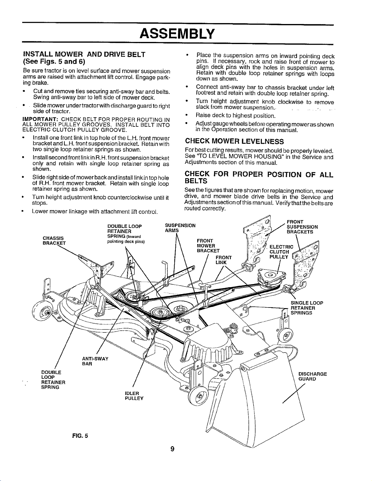
INSTALL MOWER AND DRIVE BELT
(See Figs. 5 and 6)
Be sure tractoris on level surface and mower suspension
arms are raised with attachment lift control. Engage park-
ing brake.
• Cut and remove ties securing anti-sway bar and belts.
Swing anti-sway bar to left side of mower deck.
• Slide mower under tractor with discharge guard to right
side of tractor.
IMPORTANT: CHECK BELT FOR PROPER ROUTING IN
ALL MOWER PULLEY GROOVES. INSTALL BELT INTO
ELECTRIC CLUTCH PULLEY GROOVE.
• Install one front link intop hole of the L.H. front mower
bracket and L.H. front suspension bracket. Retain with
two single loop retainer springs as shown.
• Installsecond front linkin R.H. front suspension bracket
only and retain with single loop retainer spring as
shown.
• Slide right side of mower back and install linkin top hole
of R.H. front mower bracket. Retain with single loop
retainer spring as shown.
° Turn height adjustment knob counterclockwise until it
stops.
• Lower mower linkage with attachment lift control.
DOUBLE LOOP
RETAINER
CHASSIS SPRING (Inward
BRACJ GET pointing deck pins)
• Connect anti-sway bar to chassis bracket under left
° Turn height adjustment knob clockwise to remove
• Raise deck to highest position.
• Adjust gauge wheels before operating mower as shown
CHECK MOWER LEVELNESS
For best cutting results, mower should be properly leveled.
See 'q-O LEVEL MOWER HOUSING" in the Service and
Adjustments section of this manual.
CHECK FOR PROPER POSITION OF ALL
BELTS
See thefigures that are shown for replacing motion, mower
drive, and mower blade drive belts in the Service and
Adjustments section of this manual Verify that the belts are
routed correctly.
SUSPENSION
ARMS
Place the suspension arms on inward pointing deck
pins. If necessary, rock and raise front of mower to
align deck pins with the holes in suspension arms.
Retain with double loop retainer spdngs with loops
down as shown.
footrest and retain with double loop retainer spring.
slackfrom mower suspension.. _ _ ._ _
in the Operation section of this manual.
FRONT
SUSPENSION
BRACKETS
FRONT
MOWER
BRACKET
FRONT
LINK
ELECTRIC
CLUTCH
PULLEY
DOUBLE
LOOP
RETAINER
SPRING
SINGLE LOOP
RETAINER
SPRINGS
ANTI-SWAY
BAR
DISCHARGE
GUARD
IDLER
PULLEY
FIG. 5
9

=ill
ASSEMBLY
,,"CHECKLIST
BEFORE YOU OPERATE AND ENJOY YOUR NEW
TRACTOR, WE WISH TOASSURE THAT YOU RECEIVE
THE BESTPERFORMANCEAND SATISFACTION FROM
THIS QUALITY PRODUCT.
PLEASE REVIEW THE FOLLOWING CHECKLIST:
,/ All assembly instructions have been completed.
,f No remaining loose parts in carton.
€" Battery is properly prepared and charged. (Minimum
1 hour at 6 amps).
J Seat is adjusted comfortably and tightened securely.
,I All tires are properly inflated. (For shipping purposes,
the tires were overinflated atthe factory).
,z Be sure mower deck is propedy leveled side-to-side/
front-to-rear for best cutting results. (Tires must be
properly inflated for leveling).
,/ Check mower and drive belts. Be sure they are routed
properly around pulleys and inside all belt keepers.
Z" Check wiring. See that all connections are stilf secure
and wires are properly clamped.
J Before driving tractor, be sure freewheel control is in
drive position.
WHILE LEARNING HOWTO USE YOUR TRACTOR, PAY
EXTRA ATTENTION TO THE FOLLOWING IMPORTANT
ITEMS:
#" Engine oil is at proper level.
J Fuel tank is filled with fresh, clean, regular unleaded
gasoline.
J Become familiar with all controls - their location and
function. Operate them before you start the engine.
#" Be sure brake system is in safe operating condition.
v" It is important to purge the transmission before operat-
ing your tractor for the first time. Follow proper starting
and transmission purging instructions (See'q-o START
ENGINE" and "PURGE TRANSMISSION" in the Op-
eration section of this manual).
10

i i
OPERATION
ii ii i iii ii
These symbols may appear on your tractor or in literature supplied with the product. Learn and understand their meaning.
CZ3A
BA'I-FERY CAUTION OR REVERSE FORWARD FAST SLOW
WARNING
ENGINE ON ENGINE OFF OIL PRESSURE CLUTCH LIGHTS ON LIGHTS OFF
FUEL CHOKE MOWER HEIGHT DIFFERENTIAL PARKING BRAKE UNLOCKED
LOCK LOCKED
R N H L
k
REVERSE NEUTRAL HIGH LOW
PARKING BRAKE
i
MOWER LIFT
ATTACHMENT
CLUTCH ENGAGED
ATTACHMENT
CLUTCH DISENGAGED
IGNITION
DANGER, KEEP HANDS AND FEET AWAY
HYDROSTATIC FREE WHEEL
(Hydro Models only)
11

OPERATION
KNOW YOUR TRACTOR
READ THIS OWNER'S MANUAL AND SAFETY RULES BEFORE OPERATING YOUR TRACTOR.
Comparethe illustrationswith yourtractortofamiliarize yourselfwiththe locationofvariouscontrolsand adjustments. Save
this manual for future reference.
AMMETER
cHOKECONTROL
THROTTLE CONTROL
ATTACHMENT
CLUTCH SWITCH
LIFT LEVER
PLUNGER
LIGHT SWITCH
CLUTCH/BRAKE
PEDAL
HEIGHT ADJUSTMENT
KNOB
HOURMETER
LIFT LEVER
IGNITION SWITCH
PARKING BRAKE
LEVER
MOTION
CONTROL
LEVER
FREE WHEEL CONTROL
Our tractors conform to the safety standards of the American National Standards Institute.
AI-I'AC HMENTCLUTCH SWITCH -Used toengage mower
blades orother attachments mounted to your tractor.
LIFT LEVER- Used to raiseand lower mower deck or other
attachments mounted to your tractor.
CLUTCH/BRAKE PEDAL - Used for declutching and
braking the tractor and starting the engine.
MOTION CONTROL - Selects the speed and direction of
tractor.
CHOKE CONTROL - Used when starting a cold engine.
LIGHT SWITCH - Turns the headlights on and off.
HOURMETER - Indicates hours of operation.
FIG. 6
THROI-I-LE CONTROL - Used to control engine speed.
FREEWHEEL CONTROL - Disengages transmission for
pushing or slowly towing the tractor with the engine off.
IGNITION SWITCH - Used to start and stop the engine.
AMMETER - Indicates battery charging (+) or discharging
(-).
PARKING BRAKE LEVER - Locks clutch/brake pedal into
the brake position.
HEIGHT ADJUSTMENT KNOB - Used to adjust the mower
height.
12

OPERATION
The operation of any tractor can result inforeign objects thrown into the eyes, which can result
in severe eye damage. Always wear safety glasses or eye shields while operating your tractor
or performing any adjustments or repairs.
spectacles or standard safety glasses.
I II
HOW TO USE YOUR TRACTOR
TO SET PARKING BRAKE (See Fig.7)
Your tractor is equipped with an operator presence sensing
switch. When engine is running, any attempt by the
operator to leave the seat without first setting the parking
brake will shut off the engine.
• Depress clutch/brake pedaJinto full "BRAKE" position
and hold.
• Place parking brake lever in "ENGAGED" position and
release pressure fromclutch/brake pedal. Pedal should
remaTnin"BRAKE" position. Make sure parking brake
wilt hold tractor secure.
PUSH IN TO ATTACHMENT CLUTCH
THROTTLE "DISENGAGE" SWITCH PULL OUT TO
CONTROL LEVER "ENGAGE'
CHOKE
CLUTCWBRAKE
PEDAL "BRAKE"
POSITION
IGNITION
MOTION
CONTROL
LEVER
HEIGHT
"DRIVE" ADJUSTMENT PARKING
POSITION KNOB BRAKE
"DISENGAGED .... ENGAGED"
POSITION POSITION
FIG. 7
STOPPING (See Fig, 7)
MOWER BLADES -
• Move attachment clutch switch to "DISENGAGED"
position.
GROUND DRIVE -
° Depress clutch/brake pedal intofull "BRAKE" position.
• Move motion control lever to neutrat (N) position.
IMPORTANT: THE MOTION CONTROL LEVER DOES
NOT RETURN TO NEUTRAL (N) POSITION WHEN THE
CLUTCH/BRAKE PEDAL IS DEPRESSED.
ENGINE -
• Move throttle control to slow position.
NOTE: Failureto movethrottlecontrol to slow position and
allowing engine to idle before stopping may cause engine
to "backfire".
• Turn ignition key to "OFF" position and remove key.
Always remove key when leaving tractor to prevent
unauthorized use.
• Never use choke to stop engine.
We recommend a wide vision safety mask over the
NOTE: Undercertain conditions when unit is standing idle
with the engine running, hot engine exhaust gases may
cause "browning" of grass. To eliminate this possibility,
always stop engine when stopping tractor on grass areas.
i
pletely,as described above, before leav-
CAUTION: Always stop tractor com-
ing the operator's position; to empty
grass catcher, etc.
TO USE CHOKE CONTROL (See Fig. 7)
Use choke control whenever you are starting a cold engine.
Do not use to start a warm engine.
• To engage choke control, pull knob out. Slowly push
knob in to disengage.
TO USE THROTTLE CONTROL (See Fig. 7)
Always operate engine at full throttle.
• Operating engine at less than full throttJe reduces the
battery charging rate.
• Full throttle offers the best bagging and mower perfor-
mance.
TO MOVE FORWARD AND BACKWARD
(See Fig.7)
The direction and speed of movement is controlled by the
motion control lever.
• Start tractor with motion control lever in neutral (N)
position.
° Release parking brake and clutch/brake pedal.
• Slowly move motion control lever to desired position.
TO ADJUST MOWER CUTTING HEIGHT
(See Fig.7)
The cutting height iscontrolled byturning the height adjust-
ment knob in desired direction.
• Turn knob clockwise (_) to raise cutting height.
° Turn knob counterclockwise (P_) to lower cutting
height.
The cutting height range is approximately 1-1/4" to 4-1/2".
The heights are measured from the ground to the blade tip
with the engine not running, These heights are approxi-
mate and may vary depending upon soil conditions, height
of grass and types of grass being mowed.
• The average lawn should be cutto approximately2-1/2
inches during the cool season and to over 3 inches
during hot months. For healthier and better looking
lawns, mow often and after moderate growth.
• For best cutting performance, grass over 6 inches in
height should be mowed twice. Make the first cut
relatively high; the second to desired height.
13

OPERATION
|,, i iiiii i ii
TO ADJUST GAUGE WHEELS (See Fig. 8)
Gauge wheels are properly adjusted whentheyare slightly
off the ground when mower is atthe desired cutting height
in operating position. Gauge wheels then keep the deck in
proper position to help prevent scaIping in most terrain
conditions.
• Be sure tractor is on a flat tevel surface.
• Lower mower and adjust mower to desired cutting
" height. -
• Remove retainer spring and clevis pin which secure
each gauge wheel bar.
• Lower gauge wheels to ground. Raise gauge wheels
slightly to align holes in bracket and gauge wheel bar
and insert clevis pin. Gauge whee]s should be slightly
off the ground.
• Replace retainer spring into clevis pin.
IMPORTANT: BE SURE TO READJUST GAUGE WHEELS
IF YOU CHANGE THE CUTTING HEIGHT OF TH EMOWER
DECK.
i=lG. 8
TO OPERATE MOWER (See Figs. 6 and 7)
Your tractor is equipped with an operator presence sens-
ing switch. Any attempt by the operator to leave the seat
with the engine running andthe attachment clutch engaged
will shut off the engine.
• Select desired height of cut.
• Lower mower with attachment lift control.
• Start mower blades by engaging attachment clutch
control.
• TO STOP MOWER BLADES - disengage attachment
clutch control.
TO OPERATE ON HILLS
ii i,
iA cA,.,..r,o,,,:oonot0r,voupor,'ownI
• Choose the slowest speed before starting up or down
hills.
• Avoid stopping or changing speed on hills.
• If slowing is necessary, move throttle control lever to
slower position.
• Ifstopping is absolutely necessary, push clutch/brake
pedal quickly to brake position and engage parking
brake.
• Move motion control lever to neutral (N) position.
IMPORTANT: THE MOTION CONTROL LEVER DOES
NOT RETURN TO NEUTRAL (N) POSITION WHEN THE
CLUTCH/BRAKE PEDAL IS DEPRESSED.
• To restart movement, slowly release parking brakeand
clutch/brake pedal.
• Slowly move motion control lever to slowest setting.
• Make all turns slowly.
TO TRANSPORT (See Figs. 6 and 10)
When pushing or towing your tractor, besure to disengage
transmission by placing freewheel control in freewheeling
position. Free wheel control is located at the rear drawbar
of tractor.
• Raise attachment lift to highest position with attach-
ment lift control.
Remove retainer spring from freewheel control rod.
Push control rod in to disengage transmission and
reinsert retainer spring into control rod hole now on
back side of the bracket.
• Do not push or tow tractor at more than two (2) MPH.
• To reengage transmission, reverse above procedure.
NOTE: To protect hood from damage when transporting
your tractor on a truck or a trailer, be sure hood is closed
and secured to tractor. Use an appropriate means of tying
hood to tractor (rope, cord, etc.).
hills with slopes greater than 15° and
do not drive'across any slope.
without either the entire grass catcher,
_ CAOTIC)N: Do not operate the mower
on mowers so equipped, or the dis-
charge guard in place.
'?/)<
FIG. 9 14
FIG. 10

OPERATION
BEFORE STARTING THE ENGINE
CHECK ENGINE OIL LEVEL (See Fig. 11)
• The engine in your tractor has been shipped, from the
factory, already filled with summer weight oil.
° Check engine oil with tractor on level ground.
• Unthread and remove oil fill cap/dipstick; wipe oil off.
Reinsert the dipstick into the tube and rest oil fill cap on
the tube. Do not thread the cap ontothe tube. Remove
and read oil level. If necessary, add oil until "FULL"
mark on dipstick is reached. Do not overfill.
• For cold weather operation you should change oil for
easier starting (See "OIL VISCOSITY CHART" in the
Customer Responsibilities section of this manual).
° To change engine oil, see the Customer Responsibili-
ties section in this manual.
E.G..Eo%+,0"
FIG. 11
ADD GASOLINE
• Fill fuel tank. Use fresh, ctean, regular unleaded
gasoline with a minimum of 87 octane. (Use of leaded
gasoline will increase carbon and lead oxide deposits
and reduce valve life). Do not mix oil with gasoline.
Purchase fuel in quantities that can be used within 30
days to assure fuel freshness•
IMPORTANT: WHEN OPERATING IN TEMPERATURES
BELOW 32°F(0°C), USE FRESH, CLEAN WINTER GRADE
GASOLINE TO HELP iNSURE GOOD COLD WEATHER
STARTING.
WARNING: Experience indicates that alcohol blended
fuels (called gasohol or using ethanol or methanol) can
attract moisture which leads to separation and formation of
acids during storage. Acidic gas can damage the fuel
system of an engine while in storage. To avoid engine
problems, the fuel system should be emptied before stor-
age of 30 days or longer. Drain the gas tank, start the
engine and let it run until the fuel lines and carburetor are
empty. Use fresh fuel next season. See Storage Instruc-
tions for additional information. Never use engine or
carburetor cleaner products in the fuel tank or permanent
damage may occur.
i
filler neck. Do not overfill. Wipe off any
CAUTION: Fill to bottom of gas tank
spilled oil or fuel. Do not store, spill or
use gasoline near an open flame.
TO START ENGINE (See Fig. 7)
When starting the engine for the first time or if the engine
has run out of fuel, itwilt take extra cranking time to move
fuel from the tank to the engine.
• Be sure freewheel control is in the transmission en-
gaged position.
• Sit on seat in operating position, depress clutch/brake
pedal and set parking brake•
° Place motion control lever in neutral (N) position.
• Move attachment clutch to "DISENGAGED" position.
• Move throttle control to fast position
• Pull choke control out for a cold engine start attempt.
For awarm engine start attempt the choke control may
not be needed.
Note: Before starting, read the warm and cold starting
procedures below.
• Insert keyintoignition and turnkeyclockwise to"START"
position and release key as soon as engine starts. Do
not run starter continuously for more than fifteen sec-
onds per minute. If the engine does not start after
several attempts, push choke control in, wait a few
minutes and tryagain. Ifengine still does not start, pull
the choke control out and retry.
WARM WEATHER STARTING (50° F and above)
• When engine starts, slowly push choke control in until
the engine begins to run smoothly. Ifthe engine starts
to run roughly, pull the choke control out slightly for a
few seconds and then continue to push the control in
slowly.
• The attachments and ground drive can now be used. If
the engine does not accept the load, restart the engine
and allow itto warm upfor one minute using the choke
as described above.
COLD WEATHER STARTING (50=F and below)
• When engine starts, slowly push choke control in until
the engine begins to run smoothly. Continue to push
the choke control in small steps allowing the engine to
accept small changes in speed and load, until the
choke control is fully in. If the engine starts to run
roughly, pull the choke control out slightly for a few
seconds and then continue to push the control in
slowly. This may require an engine warm-up period
from several seconds to several minutes, depending
on the temperature.
HYDROSTATIC TRANSMISSION WARM UP
• Before driving the unit in cold weather, the transmis-
sion should be warmed up as follows:
• Be sure the tractor is on level ground.
• Place the motion control lever in neutral.
Release the parking brake and let the clutch/brake
slowly return to operating position.
• Allow oneminute fortransmissiontowarm up.This
can be clone during the engine warm up period.
• The attachments can be used during the engine warm-
up period afterthe transmission has been warmed up
and may require thechoke control be pulled out slightly.
NOTE: If at a high altitude (above 3000 feet) or in cold
temperatures (below 32 F) the carburetor fuel mixture may
need to be adjusted for best engine performance. See '70
ADJUST CARBURETOR" in the Service and Adjustments
section of this manuat.
15

OPERATION
PURGE TRANSMISSION
freewheel lever while the engine isrun+
CAUTION: Never engage or disengage
ning.
To ensure proper operation and performance, it is recom-
mended that the transmission be purged before operating
tractor for the first time. This procedure will remove any
trapped air inside the transmission which may have devel-
oped during shipping of your tractor.
IMPORTANT: SHOULD YOUR TRANSM ISSION REQUIRE
REMOVAL FOR SERVICE OR REPLACEMENT, IT
SHOULD BE PURGED AFTER REINSTALLATION
BEFORE OPERATING THE TRACTOR.
• Place tractorsafely on level surface with engine offand
parking brake set.
• Disengage transmission by placing freewheel control
in freewheeling position (See "TO TRANSPORT" in
this section of manual).
• Sitting inthe tractor seat, start engine. Afterthe engine
is running, move throttle control to slow position. With
motion controt lever in neutral (N) position, slowly
disengage clutch/brake pedal.
• Move motion control lever to full forward position and
hold for five (5) seconds. Move lever to full reverse
position and hold for five (5) seconds. Repeat this
procedure three (3) times.
NOTE: Duringthis procedure there will be no movement of
drive wheels. The air is being removed from hydraulic drive
system.
• Move motion control leverto neutral (N)position. Shut-
off engine and set parking brake.
• Engage transmission by placing freewheel control in
driving position (See 'q-OTRANSPORT" inthis section
of manual).
• Sitting inthetractor seat, startengine. Afterthe engine
is running, move throttre control to hatf (1/2) speed.
With motion control lever in neutral (N) position, slowly
disengage clutch/brake pedal.
• Slowly move motion control lever forward, after the
tractor moves approximately five (5)feet, slowly move
motion control lever to reverse posttion. After the
tractor moves approximately five (5) feet return the
motion control lever tothe neutral (N) position. Repeat
this procedure with the motion control lever three (3)
times.
• Your tractor is now purged and now ready for normal
operation.
MOWING TIPS
• Tire chains cannot be used when the mower housing
is attached to tractor.
• Mower should be properly leveled for best mowing
performance. See'q-O LEVEL MOWER HOUSING" in
the Service and Adjustments section of this manual.
• Use the runner on the right hand side of mower as a
guide. The blade cuts approximately an inch outs;de
the runner (See Fig. 9).
• The left hand side of mower should be used for trim-
ming.
• Drive so that clippings are discharged onto the area
that has been cut. Have the cut area to the right of the
tractor. This will result in a more even distribution of
clippings and more uniform cutting.
• When mowing large areas, start by turning to the right
so that clippings will discharge away from shrubs,
fences, driveways, etc. After one or two rounds, mow
in the opposite direction making left hand turns until
finished (See Fig. 12).
• If grass isextremely tall, it should be mowed twice to
reduce load and possible fire hazard from dried clip-
pings. Make first cut relatively high; the second to the
desired height.
• Do not mow grass when it is wet. Wet grass will plug
mower and leave undesirable clumps. Al!ow grass to
dry before mowing.
• Always operate engine at full throttle when mowing to
assure better mowing performance and proper dis-
charge of material. Regulate ground speed by select-
ing a low enough gear to give the mower cutting
performance as wetl as the quality of cut desired.
• When operating attachments, select a ground speed
that will suit the terrain and give best performance of
the attachment being used.
f
It
-%
C
FIG. 12
16

CUSTOMER RESPONSIBILITIES
MAINTENANCE SCHEDULE j,___o_'_o__, _
FILL IN DAT ES /_/_ _U__/__ pp"
AS YOU COMPLETE ;((_ _._ _._/ _._/_.._ ._S_/_ .%_O':
REGULARSERVICE /_¢"_r___ERVICE DATES
Check Brake Operation .!## Ik/'
Check Tire Pressure if V'
T Check for Loose Fasteners V p V'z if
Sharpen/Replace Mower Blades 1##'4
A
C Lubrication Chart .. I_
T Check Battery Level/Recharge 1_6
0 Ctean Battery and Terminals If if
a CheckTransaxle Cooling If
Adjust Blade Belt(s) Tension Ks
Adjust Motion Drive Belt(s) Tension 1##'5
Check Engine Oil Level I_
Change Engine Oil _1.2.3 V _'
Clean Air Fitter 1_2
E
Clean Air Screen
N
G Inspect MufflerlSparkArrester
I Replace Oi! Filter (If equipped) Ik_t2
CEean Engine Cooling Fins 11/'2
Replace Spark PFug If
Replace Air Filter Paper Cartridge t/2
Replace Fuel Fiffer V _
1 - Change more oftenwhen operatmg under a heavy load or in htgh ambient temperatures.
2 - Service more often when operating indirty or dusty condJttons.
3 - If equipped with oil filter, change oil every 50 hours.
4 - Replace blades more often when mowing tn sandy soil.
t 111111nnn
GENERAL RECOMMENDATIONS
The warranty on this tractor does not cover items that have
been subjected to operator abuse or negligence. To
receive full value from thewarranty, operator must maintain
tractor as instructed in this manual.
Some adjustments will need to be made periodically to
properly maintain your tractor.
All adjustments in the Service and Adjustments section of
this manual should be checked at least once each season.
Once a yearyou should replace the spark plug, clean
or replace air filter, and check blades and belts for
wear. A new spark plug and clean air filter assure
proper air-fuel mixture and help your engine run better
and last longer.
,, , ,,,
" ,, i
5 - If equipped with adiustable system,
6 - Notrequired it equipped wuthmaintenance-free battery.
7 - Tighten front axle pivot bolt to 35 ft -Ibs. maxtmum.
Do not overhghten.
LUBRICATION CHART
(_)TIE ROD BALL JOINTS
(_) SPINDLE
(_)FRONT WHEEL (_)
BEARING ZERK BEARING ZERK
(_) STEERINC
SECTOR GEAR ENGINE (_)
TEETH
ZERK(_)
i r
BEFORE EACH USE
• Check engine oil level.
- Check brake operation.
• Chock tire pressure,
• Check for loose fasteners.
IMPORTANT: DO NOT OIL OR GREASE THE PIVOT POINTS
WHICH HAVE SPECIAL NYLON BEARINGS. VISCOUS LUBRI-
CANTS WILL ATTRACT DUST AND DIRT THAT WILL SHORTEN
THE LIFE OF THE SELF-LUBRICATING BEARINGS. IF YOU
FEEL THEY MUST BE LUBRICATED, USE ONLY A DRY, POW-
DERED GRAPHITE TYPE LUBRICANT SPARINGLY.
(_ SPRAY SILICONE LUBRICANT (MOVE BOOTS TO LUBRICATE)
(_) GENERAL PURPOSE GREASE
(E) REFER TO CUSTOMER RESPONSIBILITIES "ENGINE" SECTION
17
CUSTOMER RESPONSIBILITIES
TRACTOR
Always observe safety rules when performing any mainte-
nance.
BRAKE OPERATION
If tractor requires more than six (6)feet stopping distance
at high speed inhighest gear, then brake must beadjusted.
(See "TO ADJUST BRAKE" in the Service and Adjust-
ments section of this manual).
TIRES
• Maintain proper air pressure in all tires (See "PROD-
UCT SPECIFICATIONS" on page 3 of this manual).
• Keep tires free of gasoline, oil, or insect control chemi-
cals which can harm rubber.
• Avoid stumps, stones, deep ruts, sharp objects and
other hazards that may cause tire damage.
NOTE: To seal tire punctures and prevent flat tires due to
slow leaks, tire sealant may be purchased from your local
parts dealer. Tire sealant also prevents tire dry rot and
corrosion.
BLADE CARE
For best results mower blades must be kept sharp. Re-
place bent or damaged blades.
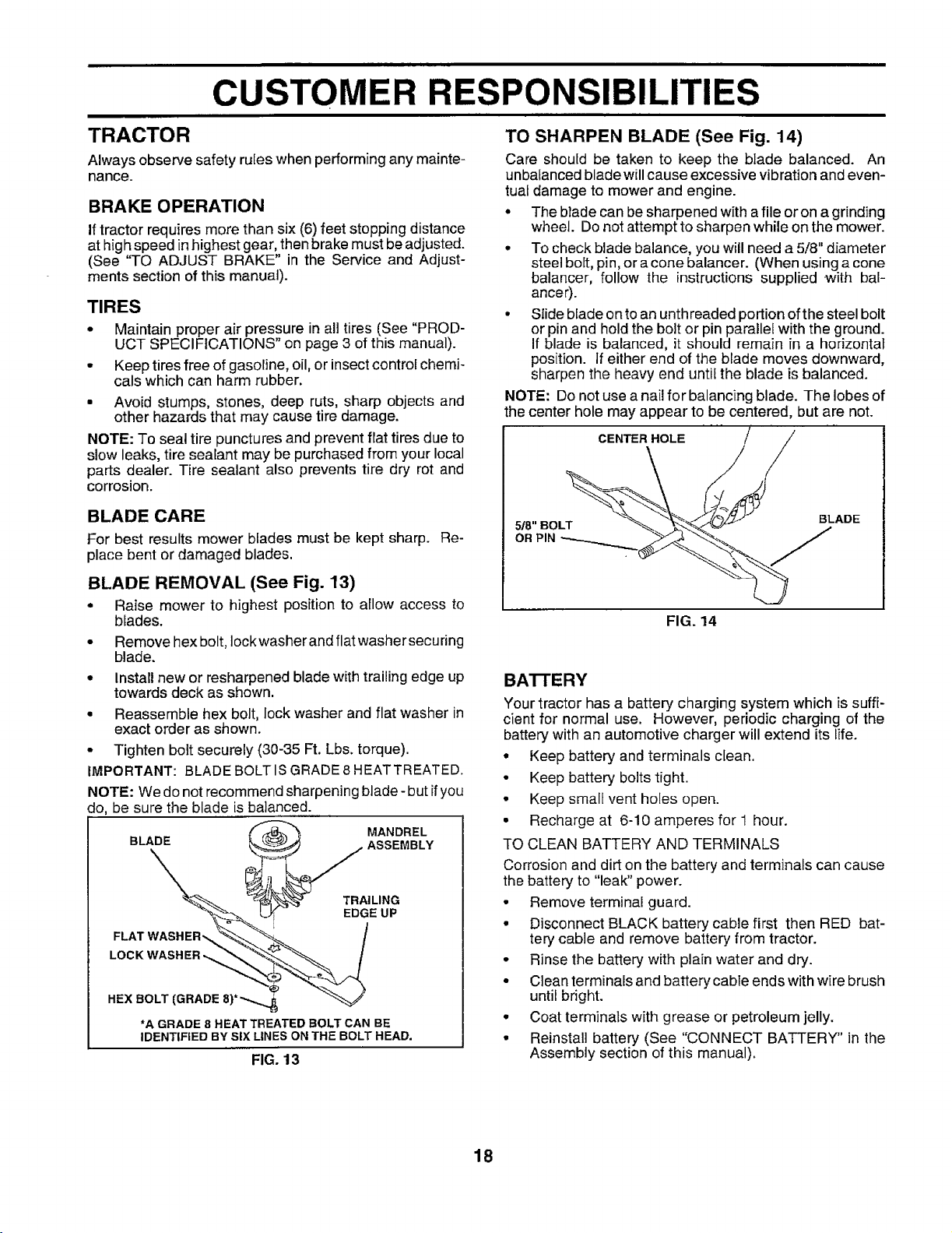
BLADE REMOVAL (See Fig. 13)
• Raise mower to highest position to allow access to
blades.
• Remove hex bolt, Iockwasher and flat washer securing
blade.
• Install new or resharpened blade with trailing edge up
towards deck as shown.
• Reassemble hex bolt, lock washer and flat washer in
exact order as shown.
• Tighten bolt securely (30-35 Ft. Lbs. torque).
IMPORTANT: BLADE BOLT IS GRADE 8HEATTREATED.
NOTE: Wedo not recommend sharpening blade- butifyou
do, be sure the blade is balanced.
MANDREL
BLADE Lk_L--_'_ - ASSEMBLY
_'_ L__ EDGE UP
LOCKWASHER-._ _
HEX BOLT (GRADE 8)*"-.._
*A GRADE 8 HEAT TREATED BOLT CAN BE
IDENTIFIED BY SIX LINES ON THE BOLT HEAD.
FIG. 13
TO SHARPEN BLADE (See Fig. 14)
Care should be taken to keep the blade balanced. An
unbalanced blade willcause excessive vibration and even-
tual damage to mower and engine.
• The blade can be sharpened with afile or on agrinding
wheel. Do notattempt to sharpen while on the mower.
• To check blade balance, you will need a 5/8" diameter
steel bolt, pin, or a cone balancer. (When using a cone
balancer, follow the instructions supplied with bal-
ancer).
• Slide blade on to an unthreaded portion ofthe steel bolt
or pinand hold the bolt or pin parallel with the ground.
If blade is balanced, it should remain in a horizontal
position. If either end of the blade moves downward,
sharpen the heavy end until the blade is balanced.
NOTE: Do not use a nail for balancing blade. The lobes of
the center hole may appear to be centered, but are not.
CENTER HOLE
/
5/8"BOLT BLADE
OR PIN j
FIG. 14
BA'I-rERY
Your tractor has a battery charging system which is suffi-
cient for normal use. However, periodic charging of the
battery with an automotive charger will extend its life.
* Keep battery and terminals clean.
• Keep battery bolts tight.
o Keep small vent holes open.
• Recharge at 6-10 amperes for 1 hour.
TO CLEAN BATTERY AND TERMINALS
Corrosion and dirt on the battery and terminals can cause
the battery to "leak" power.
° Remove terminal guard.
° Disconnect BLACK battery cable first then RED bat-
tery cable and remove battery from tractor.
• Rinse the battery with plain water and dry.
• Clean terminals and battery cable ends with wire brush
until bright.
• Coat terminals with grease or petroleum jelly.
° Reinstall battery (See "CONNECT BATTERY" in the
Assembly section of this manual).
18
 Loading...