

Craftsman 917258543 Owner’s Manual

[RI /:TXH nN°
MODEL NUMBER 917.258543 OWNER'SMANUAL
oAssembly
° Operation
oCustomer Responsibilities
oService and Adjustments
° Repair Parts
.......GAUTION: Read and follow all safety rules and instructions before operating this equipment.
FOR CONSUMER ASSISTANCE HOT LINE, CALLTHIS TOLL FREE NUMBER: 1-800-659-5917
_-_'11 IIIIIIIIIIIIIIIIIIIIIIII I IIIIIIIIII'NIII
II1[ _ IIl_ll_'llL. z:_
SAFETY RULES
A Safe Operation Practices for Ride-On Mowers &
IMPORTANT: THIS CUTTING MACHINE IS CAPABLE OF AMPUTATING HANDS AND FEET AND THROWING OBJECTS,
FAILURE TO OBSERVE THE FOLLOWING SAFETY INSTRUCTIONS COULD RESULT IN SERIOUS INJURY OR DEATH.
I.
GENERAL OPERATION
Read understand, and follow all instructions in the manual
and on the machine before starting
Only allow responsible adults who are familiar with the
instructions, to operate the machine
Clear the area of objects such as rocks toys, wire etc,
which could be picked up ahd tl_ro_fi b_/the blade:
t
Be sure the area is clear of other people before mowing Stop
machine if anyone enters the area.
Never carry passengers.
Do not mow in reverse unless absolutely necessary. Always
look down and behind before and while backing,
Be aware of the mower discharge direction and do not point
it at anyone Do not operate the mower without either the
entire grass catcher or the guard in place,
• Slow down before turning.
o Never leave a running machine unattended, Aiways turn off
blades, set parking brake, stop engine, and remove keys
before dismounting,
- Turn off blades when not mowing
• Stop engine before removing grass catcher or unclogging
chute
- Mow only in daylight or good artificial light,
• Do not operate the machine while under the influence of
alcohol or drugs
• Watch for traffic when operating near or crossing roadways
• Use extra care when loading or unloading the machine into
a trailer or truck
II, SLOPE OPERATION
Slopes are a major factor related to loss of control and
tipover accidents which can result in severe injury or death
All slopes require extra caution If you cannot back up the
slope or if you feet uneasy on it do not mow it
DO:
• Mow up and down slopes, not across
• Remove obstacles such as rocks, tree limbs, etc
• Watch for holes, ruts, or bumps Uneven terrain could
overturn the machine Taft grass can hide obstacles
• Use slow speed Choose a low gear sothat you will not have
to stop or shift while on the slope
• Follow the manufacturer's recommendations for wheel
weights or counterweights to improve stability
• Use extra care with grass catchers or other attachments
These can change the stability of the machine
• Keep all movement on the slopes slow and gradual Do not
make sudden changes in speed or direction
• Avoid starting or stopping on a slope If tires lose traction
disengage the blades and proceed slowly straight down the
slope,,
.... DO N_OTL
Do not turnOnslopes unless necessa_ a_ th6n, fur#;_16_ly ................
and gradually downhill, if possible
Do not mow near drop offs ditches or embankments The
mower could suddenly turn over if a wheel isover the edge
of a cliff or ditch, or il an edge caves in
• Do not mow on wet grass° Reduced traction could cause
sliding
• Do not try to stabilize the machine by putting your foot on the
ground
• Do not use grass catcher on steep slopes
ill, CHILDREN
Tragic accidents can occur ifthe operator is not alert to the
presence of children. Children are often attracted to the
machine and the mowing activity Never assume that
children will remain where you last saw them,
- _eepci3iLdrenoutofthemowing areaandunderthewatchful
care ofanother reslhdnsibleadult :
, Be alert and turn machine off if children enter the area
• Before and when backing, look behind and down for small
children
• Never carry children They may fall off and be seriously
injured or interfere with safe machine operation
• Never allow children to operate the machine
• Use extra care when approaching blind corners shrubs
trees, or other objects that may obscure v_slon
iV. SERVICE
• Use extra care {nhandling gasoline and other fuels They are
flammable and vapors are explosive,,
Use only an approved container
Never remove gas cap or add fue! with the engine
running Allow engine to cool before refueling Do not
smoke
Never refuel the machine indoors
Never store the machine or fuel container inside where
there is an open flame, such as a water heater
• Never run a machine inside a closed area
• Keep nuts and bolts, especially blade attachment bolts tight
and keep equipment in good condition
o Never tamper with safety devices Check their proper
operation regularly
• Keep machine lree of grass, leaves, or other debds build-up
Clean oil or fuel spillage Allow machine to coot before
storing
• Stop and inspect the equipment if you strike an oh}act
Repair, if necessary before restarting
• Never make adjustments or repairs with the engine running
• Grass catcher components are subject to wear, damage, and
deterioration, which could expose moving parts or allow
objects to be thrown Frequently check components and
replace with manufacturer's recommended parts, when nec-
essary.
° Mower blades are sharp and can cuL Wrap the blade(s) or
wear gloves, and use extra caution when servicing them,,
• Check brake operation frequently. Adjust and service as
required°
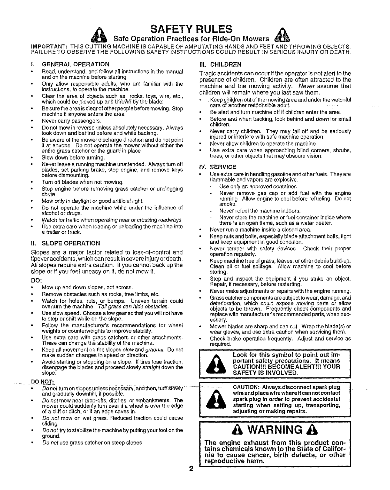
portant safety precautions. It means
Look for this symbol to point out im-
CAUTIONI!! BECOME ALERTII! YOUR
.L i n u.,ll. I n I I
iii ii ii iii iiii i
SAFETY IS INVOLVED.
CAUTION_ _Always.disconnect spark plug
spark plug in order to prevent accidental
wire and place wire where it cannot contact
starting when setting up, transporting,
adjusting or making repairs.
,,,,,,,,,,,,,,,,,, ii n,,,,,IJl i,,,i, i I
& WARNING A
The engine exhaust from this product con-
tains cl-iemicals known to the State of Califor-
nia to cause cancer, birth defects, or other
reproductive harm.
iin ,, i inun,i iiii,J Ji,,,,w

CONGRATULATIONS on your purchase of a Sears
Tractor° It has been designed, engineered and manufac-
tured to give you the best possible dependability and
performance.
PRODUCT SPECIFICATIONS
HORSEPOWER: 15.0
GASOLINECAPACITY 1..25GALLONS
ANDTYPE: UNLEADED REGULAR
Should you experience any problem you cannot easily
remedy, please contact your nearest Sears Authorized
Service Center/Departmento We have competent, we[F
trained technicians and the proper' tools to service or repair
this tractor_
Please read and retain this manual The instructions will
enable you to assemble and maintain your tractor properly.
Always observe the "SAFETY RULES".
MODEL
NUMBER 917.258543
SERIAL
NUMBER
OIL TYPE (API-SF/SG/SH):
SAE 10W30 (above 32°F)
SAE 5W-30 (below 32 F)
OiL CAPACITY: W/FILTER: 4.0 PINTS
WiO FILTER: 3.5 PtNT8
SPARK PLUG: CHAMPION RC12YC
(GAP: .040")
VALVE CLEARANCE: NO-["ADJUSTABLE
GROUND SPEED(MPH): FORWARD:
1st 1_1
2nd 1.5
3rd 2,3
4th 3.5
5th 4,4
6th 5.7
DATEOFPURCHASE
THE MODEL AND SERIAL NUMBERS WILL BE FOUND
ON A PLATE UNDER THE SEAT.
YOUSHOULDRECORDBOTHSERIALNUMBERAND
DATE OF PURCHASE AND KEEP IN A SAFE PLACE
FOR FUTURE REFERENCE,
MAINTENANCE AGREEMENT
A Sears Maintenance Agreement is available on this prod-
uct. Contact your nearest Sears store for'details.
TIRE PRESSURE: FRONT: 14 PSI
CHARGING SYSTEM: 3 AMPS BATTERY
BATTERY: AMP/HR: 30
BLADE BOLT TORQUE: 30-35 FT_LBS.
WARNING: This tractor is equipped with an interna
combustion engine and should not be used on or near any
REVERSE: 1.7
REAR: 10 PSI
5 AMPS HEADLIGHTS
MIN, CCA: 240
CASE SIZE: U1R
unimproved forest-covered, brush-covered or grass-cow
CUSTOMER RESPONSIBILITIES
• Read and observe the safety rutes.
° Followa regularschedulein maintaining,caring forand
using your tractor.
• Follow the instructions under"Customer Responsibili-
ties" and "Storage" sections of this owner's manual.
ered land unless the engine's exhaust system is equipped
with a spark arrester meeting applicable local or state taws
(if any)_ If a spark attester is used, it should be maintained
in effective working order by the operator.
In the state of California the above is required by law
(Section 4442 of the California Public Resources Code)°
Otherstates rnay have similar laws° Federal laws apptyon
federal land& A spark arrestor for the muffler is available
through your nearest Sears Authorized Service Cented
Department (See REPAIR PARTS section of this manual).
i1 n,unn,,,,,,n,,= I u
LIMITED TWO YEAR WARRANTY ON CRAFTSMAN RIDING EQUIPMENT
Fortwo(2) yearsfromthe date ofpurchase,ifthisCraftsman Riding Equipmentismaintained,lubricatedandtunedupaccording to
the instructionsin the owner's manual, Sears willrepairor replace, free of charge,any partsfound to be defective in matedaior
workmanship.
This Warranty does notcover:
• Expendable itemswhich becomeworn duringnormal use,such as blades,spark plugs,air cleaners, belts,etc;
• Tire replacementor repaircaused by puncturesfrom outsideobjects,such as halts,thorns,stumps, orglass.
, Repairs necessary because of operatorabuse negligence, improper'storage oraccident or thefailure to maintainthe
equipment according to the instructionscontained {nthe owner's manual
• Riding equipment used for commercialorrenta! purposes.
LIMITED 90 DAY WARRANTY ON BATTERY
:For- ninety-(90) days from dateof purchase;if any battery included with this riding equipment_provesdefective_{n material or
workmanship and ourtesting determines the battery will not holda charge, Searswill replacethe batteryat no charge..
IN-HOME WARRANTY SERVICE ON YOURCRAFTSMAN RIDING EQUIPMENTiSAVAILABLEAT NO-CHARGE FOR 30 DAYS
FROM THE DATE OF PURCHASE. PLEASE CONTACT YOUR NEARESTSERVICE CENTER. AFTER 30 DAYS FROM THE
DATE OF PURCHASE,WARRANTY SERVICE1SAVAILABLE BY TAKINGYOUR CRAFTSMAN RIDING EQUIPMENTTO YOUR
NEAREST SEARS SERVICE CENTER. (IN-HOMEWARRANTY SERVICEWiLL STILL BE AVAILABLE AFTER 30 DAYS FROM
THE DATE OF PURCHASE BUT A STANDARD TRiP CHARGEWiLL APPLY.) THIS WARRANTY APPLIES ONLY WHILE THIS
PRODUCT IS IN THE UNITED STATES.
This Warranty gives you specific legalrights, and you may also have ether rightswhich may varyfrom state to state_
SEARS, ROEBUCK AND CO., D/817 WA, HOFFMAN ESTATES, IL 60179
=1,1 m m 11'="nHMUl = ,'U In U = ImH'l
TABLE OF CONTENTS
SAFETY RULES ............................................................ 2
PRODUCT SPECIFICATIONS ...................................... 3
CUSTOMER RESPONSIBILITIES ..................... 3, 15-19
WARRANTY .................................................................. 3
TABLE OF CONTENTS ............................................... 4
ASSEMBLY ................................................................ 7-9
OPERATION ............... ;........................................... 10-14
INDEX
A
Accessories ........................................... 5
Adjustments:
Brake ................................................ 22
Carburetor ..................................... 25
Mower:
Front-To-Back .......................... 21
Side-To-S_de ............................ 21
Throttle Control Cable ................. 25
Air Filter, Engine ..................................... t 8
Air Screen, Engine ................................. 18
Assembly .................................................. 7-9
B
Battery:
Charging ......................................... 7
Cleaning .............................................16
Starting with Weak Battery .......... 23
Storage .............................................. 26
Terminals ......................................... 16
Belts:
Motion Drive
Removal/Replacement ...............22
Mower Blade Drive
Removal!Replacement ........... 22
Blade:
Sharpening ..................................... 16
Replacement ....................................16
Brake Adjustment .......................................22
C
Carburetor Adjustment ....................... 25
Controls, Tractor .................................. 11
Customer Responsibilities ..............15-19
Engine:
Air Filter.........................................18
Air Screen, Engine ..................... 18
Battery .......................................... t7
Cooling Fins, Engine ................. 18
Engine Oil ......................................17
Fuel Filter,........................................19
Spark Plugs .................................18
Tractor:
.... Blades k;_Z., ........ :.........:.,:.;..Lo,:.o:16
Lubrication Chart ......................15
Maintenance Schedule ............ 15
Tire Care .:................... 9,t6,23
Cutting Height, Mower'. .........................12
E
Electrical:
Interlocks and Relays .....................24
Schematic .............................................29
Wiring Diagram ............................... 30
Engine:
Air Filter ...........................................18
Air Screen .....................................18
Cooling Fins, Engine .................... 18
Oil Change ..........................................17
Oil Level ..................................... 13,17
0iiType ...............................................17
Preparation ...................................... 13
Repair Parts ...............................48-53
Starting..................................................14
Storage ..................................................26
Filters:
Air..................................................18
Fuel...................................................19
Fuel:
Type .......................................................13
Storage............................................26
Fuse .......................................... 24
Gauge Wheels ...........................................8
Hoed Removal/Installation ................. 24
Leveling Mower Deck ..............................21
Lubrication Chart ........................................ 15
Maintenance Schedule ..........................15
Mower:
Adjustment, Front-to-Back .............21
Adjustment, Side-to-Side ..............2t
Blade Sharpen ng ....................... 16
Blade Replacement .................... 16
Cutting Height ......................................12
Installation ............................................ 20
Operation ............................................t3
Removal .................................................20
Mowing Tips ...............................................14
Muffler_......................................................18
Spark Arrester ............................. 3,40
....MulcherPlate..,,,,,.......................................9
Oil:
Cold Weather Conditions ..........14,17
Engine .............................................t7
Storage.............................................. 26
MAINTENANCE SCHEDULE ....................................... 15
SERVICE AND ADJUSTMENTS ............................ 20-25
STORAGE ................................................................... 26
TROUBLESHOOTING .............................................. 27-28
REPAIR PARTS - TRACTOR ................................. 30-47
REPAIR PARTS- ENGINE .................................... 48-53
PARTS ORDERING/SERVICE .................. BACK PAGE
Operation.............................................10-I4
Operating Mower. .....................................13
Options:
Accessories ...............................................5
Spark Attester ...........................3,40
P
Parking Brake .....................................11-t2
PartsBag ......................................................6
Parts, Replacement/Repair ...............30-47
Product Specifications .............................3
R
F
Repair Parts ..................................... 30-47
S
Safety Rules ................................................2
Seat ............................................................8
Service and Adjustments ..................20-25
Brake .................................................22
G
H
L
M
Carburetor ................................... 25
Fuse ..................................................24
Hood Removal/Insta!latien .............24
Motion Drive Belt
Remova!/Replacement ............22
Mower Blade Drive Belt
•Removal/Replacement ............22
Mower Adjustment:
Front-to-Back ..............................21
Side-to-Side ................................21
Mower Installation .............................20
Mower Removal ..............................20
Tire Care ................................ 9,16,23
Slope Guide Sheet .....................................55
Spark Plugs ..............................................18
Specifications .......................................... 3
Starting the Engine ..............................13-14
Steering Wheel ....................................7,23
Stopping the Tractor _..................................12
Storage ........................................................26
T
Throttle Control Cable Adjustment ......25
Tires...............................................9 16,23
0
Trouble Shooting Chart ......................27-28
Transaxle Repair Parts ......................46-47
W
Warranty ..........................................................3
Wiring Diagram ...................................... 30
Wiring Schematic ....................................29
i IH,,,,I,,II nl ,,,,,,,,,, ,,,,,,, lUl II1,111111111lUln I! nnn in nl nlnn,
ACCESSORIES AND ATTACHMENTS
iiiiiiiiiiiiiiiiiii iii iiiiiiiiiiiii i iiiiiii iii ...... ii iiiiiiiiiiiiiiiiiiiii i iiiiiiiiiiiii i i iiiiiiiiiiiii
These accessories and attachments were available through most Sears retail outlets and service centers when the tractor was purchased..
Most Sears stores can order these items for you when you provide the model number' of your tractor°
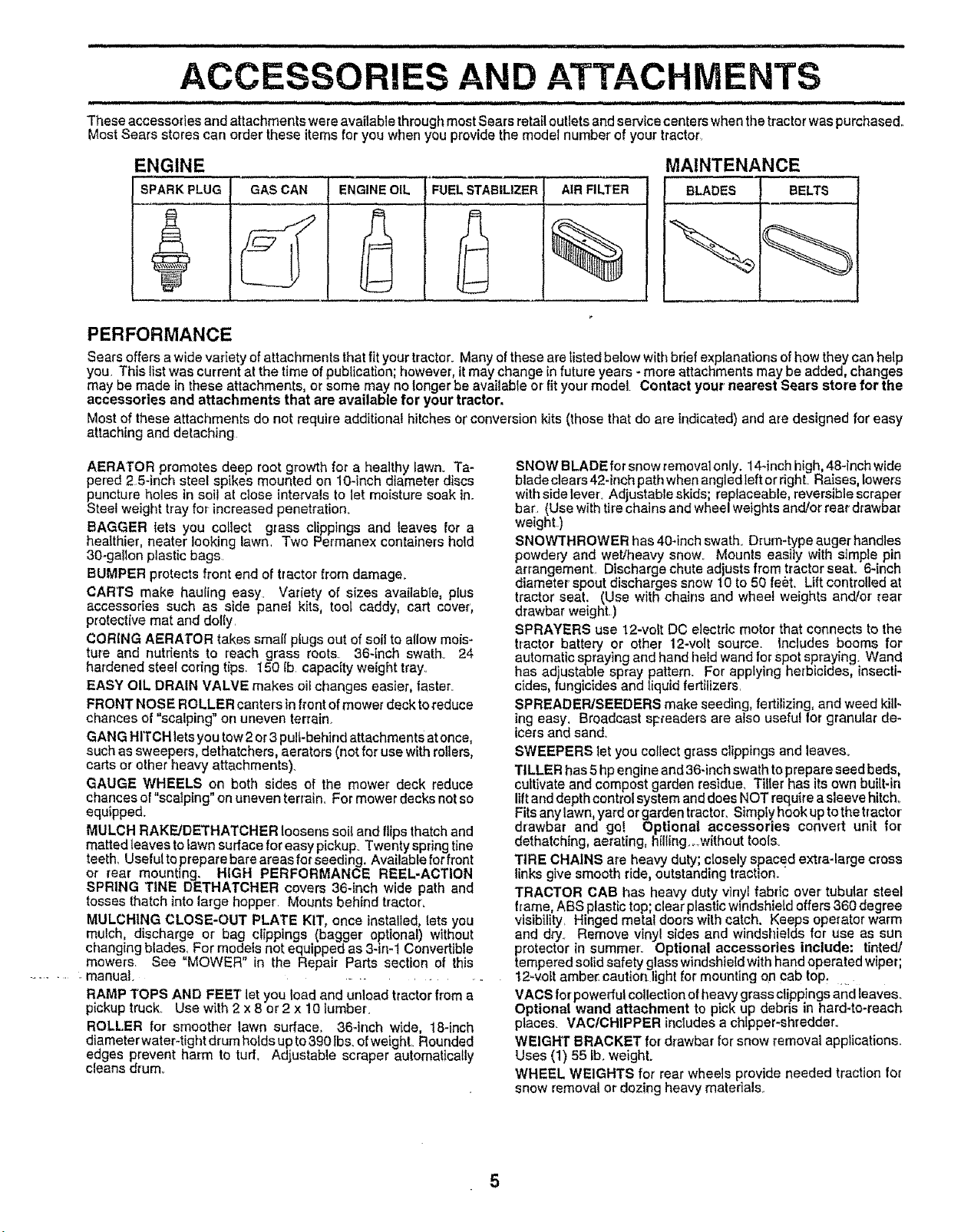
ENGINE MAINTENANCE
SPARK PLUG GAS CAN ENGINE OIL FUELSTABILIZER AIR FILTER BLADES BELTS
PERFORMANCE
Sears offers a wide variety of attachments thatfit your tractor. Many of these are tisted below with brief explanations of how theycan help
you. This list was current at the time ofpublication; however, it may change in future years - more attachments may be added, changes
may be made in these attachments, or some may no tonger be available or fit your model Contact your nearest Sears store for the
accessories and attachments that are available for your tractor.
Most of these attachments do not require additional hitches or conversion kits (those that do are indicated) and are designed for easy
attaching and detaching
AERATOR promotes deep root growth for a healthy lawn. Ta-
pered 2 54nch steel spikes mounted on 10-inch diameter discs
puncture holes in soil at close intervals to let moisture soak in..
Steel weight tray for increased penetration.
BAGGER iets you collect grass clippings and leaves for a
healthier, nearer looking lawn. Two Permanex containers hold
30-gallon plastic bags.
BUMPER protects front end of tractor from damage_
CARTS make hauling easy. Variety of sizes available, plus
accessories such as side panel kits, tool caddy, cart cover,
protective mat and dolly.
CORING AERATOR takes small plugs out of soil to allow mois-
ture and nutrients to reach grass roots 36-inch swath° 24
hardened steel coring tips. 1501b capac{tyweighttray_
EASY OIL DRAIN VALVE makes oil changes easier, faster_
FRONT NOSE ROLLER canters in front of mower deck to reduce
chances of "scalping" on uneven terrain.
GANG HITCH lets you tow 2 or 3 pull-behind attachments at once,
such as sweepers, dethatchers, aerators (not for' use with roUers,
carts or other heavy attachments).
GAUGE WHEELS on both sides of the mower deck reduce
chances of "scalping" on uneven terrain_ For mower decks not so
equipped.
MULCH RAKE/DETHATCHER loosens soil and flips thatch and
matted leaves to lawn surface for easy pickup. Twenty spring tine
teeth.. Uselultopreparebareareasfcrseeding, Availableforfront
or rear mounting. HIGH PERFORMANCE REEL-ACTION
SPRING TINE DETHATCHER covers 36-inch wide path and
tosses thatch into large hopper. Mounts behind tractor.
MULCHING CLOSE-OUT PLATE KIT, once installed, lets you
mulch, discharge or bag clippings (bagger optional) without
changing blades, For models not equipped as 3-in-1 Convertible
mowers. See "MOWER" in the Repair Parts section of this
manual .........
RAMP TOPS AND FEEl" let you load and unload tractor from a
pickup truck. Use with 2 x 8 or 2 x 10 lumber.
ROLLER for smoother lawn surface. 36-inch wide, 18-inch
diameter water-tight drum holds up to 390Ibs. of weight.. Rounded
edges prevent harm to turf. Adjustable scraper automatically
cleans drum.
SNOW BLADEfor snowremovalonly. 14-inch high,48-1nchwide
btade clears 424nch path when angledteft or righL Raises, lowers
with side lever_.Adjustable skids; replaceable, reversible scraper
bar. (Use with tire chains and wheel weights and/or rear drawbar
weight )
SNOWTHROWER has 40-inch swath. Drum4ype auger handles
powdery and wet/heavy snow_ Mounts easily with simple pin
arrangement. Discharge chute adjusts from tractor seat. 6-inch
diameter spout discharges snow 10 to 50 feet. Lift controlled at
tractor seat. (Use with chains and wheel weights and/or rear
drawbar weight.)
SPRAYERS use 12-volt DC electric motor that connects to the
tractor battery or other 12-volt source Includes booms for
automatic spraying and hand held wand for Spot spraying. Wand
has adjustable spray pattern. For applying herbicides, insecti-
cides, fungicides and liquid fertilizers.
SPREADEPJSEEDERS make seeding, fertilizing, and weed kitl-
}ng easy, Broadcast spreaders are also useful for granular de-
tcefs and sand..
SWEEPERS let you collect grass clippings and leaves_
TILLER has 5hp engine and 36-inch swath to prepare seed beds,
cultivate and compost garden residue. Tiller has its own built-in
lift and depth control system and does NOT require a sleeve hitch_
Fits any lawn, yard or garden tractor. Simply hook up tothe tractor
drawbar and go! Optional accessories convert unit for
dethatching, aerating, hil_ing.o.witheut tools.
TIRE CHAINS are heavy duty closely spaced extra-large cross
links give smooth ride, outstanding tractlon_
TRACTOR CAB has heavy duty vinyl fabric over tubular steel
f_ame, ABS plastic top; clear plastic windshield offers 360 degree
visibility. Hinged metal doors with catch. Keeps operator warm
and dry. Remove vinyl sides and windshields for use as sun
protector in summer.. Optional accessories include, tinted/
tempered solid safety glass windshield with hand operated wiper;
12_volt amber, caution light for mounting on cab top.._
VACS for powerful co!lection of heavy grass clippings and {eaves°
Optional wand attachment to pick up debris in hard4o-reach
places. VAC/CHIPPER includes a chipper-shredder.
WEIGHT BRACKET for drawbar for snow removal applications..
Uses (1) 55 Ib. weight.
WHEEL WEIGHTS for' rear wheels provide needed traction for
snow removal or dozing heavy material&
5
i ,,,, .... i1,1,,i ..................... _ "",, ..........
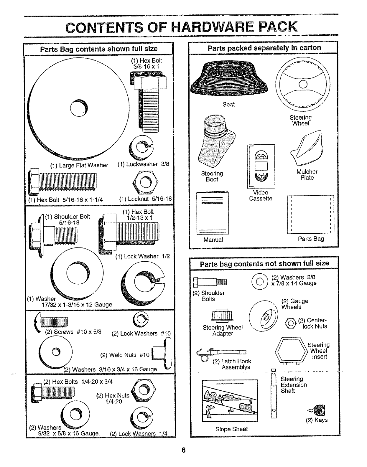
CONTENTS OF HARDWARE PACK
Parts Bag contents shown full size
(1) Hex Bolt
3/8-16 x 1
©
G
Seat
Steering
Wheel
(1) Large Flat Washer
(1) Hex Bolt 5/16-18 x 1-1/4
-J 5/16-18
(1) Shoulder Bolt [_ [
=z_ _r =__x (1) Lock Washer 1/2
(1) Was
17/32 x 1-3/16 x 12 Gauge
i iii, ,111 i,i,
_ws #10 x 5/8 (2) Lock Washers #10
(t) Lockwasher 3/8
(1) Lecknut 5/16_18
.......... ,11....................
(1) Hex Bolt
1/2-13 x t
Steering
Boot
Video
Cassette
Manual
-._ i i,i i, i
Hill III1'
Parts bag contents not shown full size
(2) Shoulder
Bo}ts
Steering Wheel
Adapter
(2) Latch Hook
Assemblys
, ,i,,,111 i i,, ii ,i i,iiii
x 7/8 x 14 Gauge
2) Washers 3/8
Mulcher
Plate
I t
......... T
Parts Bag
Wheels
(2) Center -
(2) Gauge
lock Nuts
Swteering
heel
Insert
t
i
!
(2) Hex Bolts 1/4-20 x 3/4
(2) Washer,, _ _ !/4-20
9/32 x 5/8 x 16 Gauge 12) Lock Washers 1/4
(2) Hex Nuts
Steering
--- Extension
Shaft
o
- (2) Keys
SJope Sheet
6
ASSEMBLY
= nn mnH n= ,,Hi =
Your new tractor has been assembled at the factory with exception of those parts {eft unassembled for shipping purpose&
To ensure safe and proper operation of your tractor all parts and hardware you assemble must be tightened securely. Use
the correct tools as necessary to insure proper tightness,
TOOLS REQUIRED FOR ASSEMBLY
A socket wrench set will make assembly easier, Standard
wrench sizes are listed.
(1) 3/4" Socket w/drive rachet
(2) 7/16" wrenches (1) Phillips Screwdriver
(2) 1/2" wrenches Tire pressure gauge
(1) 9/16" wrench Utility knife
When right or left hand is mentioned in this manual, it
means when you are in the operating position (seated
behind the steering wheel),
TO REMOVE TRACTOR FROM CARTON
UNPACK CARTON
• Remove all accessible loose parts and parts cartons
from carton (See page 6).
• Cut, from top to bottom, along lines on all four'corners
of carton, and lay panels flat.
• Check for any additional loose parts or cartons and
remove.
BEFORE ROLLING TRACTOR OFF SKID
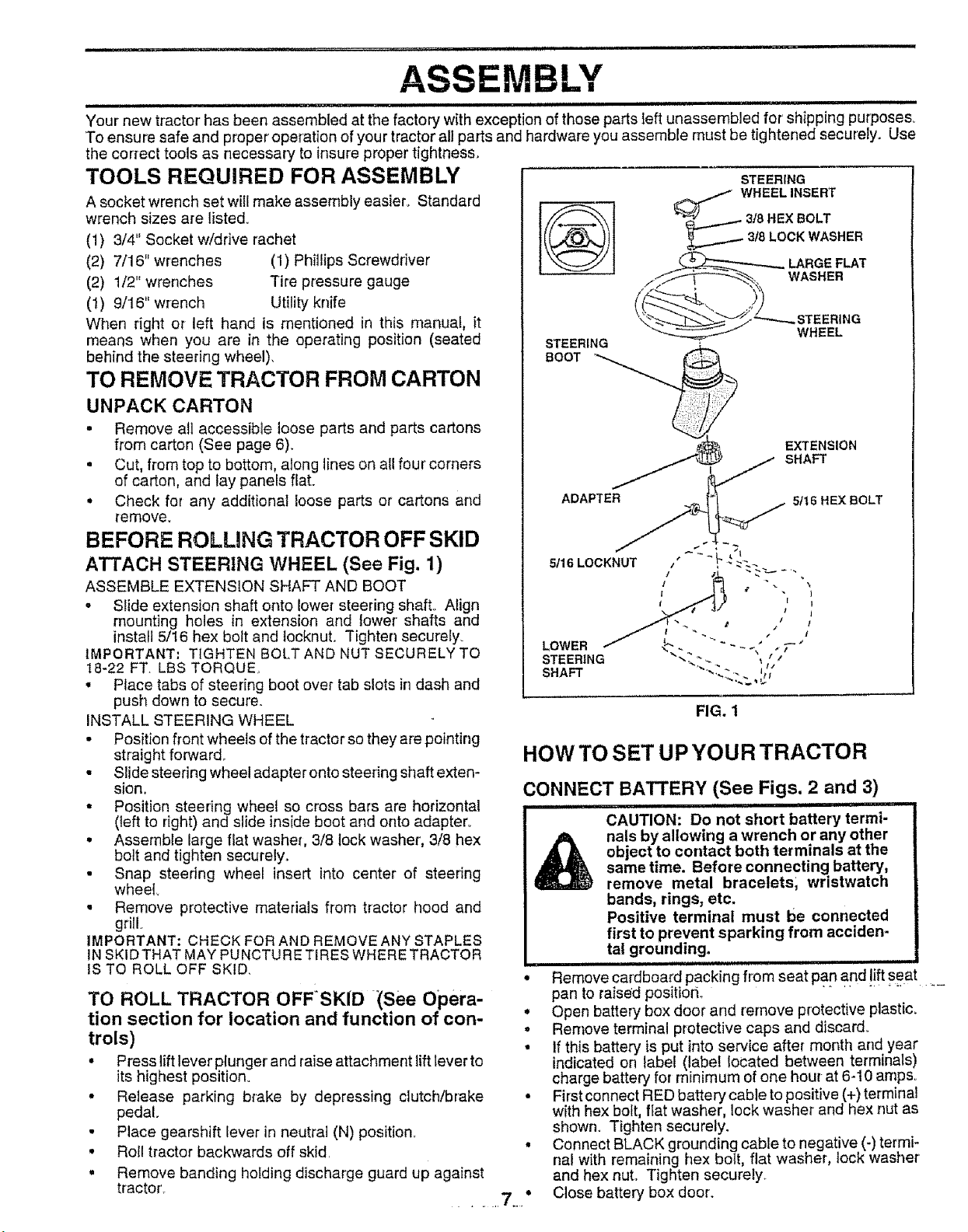
ATTACH STEERING WHEEL (See Fig, 1)
ASSEMBLE EXTENSION SHAFT AND BOOT
° Slide extension shaft onto lower steering shaft., Align
mounting holes in extension and lower shafts and
install 5/16 hex bolt and locknut. Tighten securely.
IMPORTANT; TIGHTEN BOLT AND NUT SECURELY TO
18-22 FT LBSTORQUEr
• Place tabs of steering boot over tab slots in dash and
push down to secure,
INSTALL STEERING WHEEL
• Position front wheels of the tractor so they are pointing
straight forward.,
• Slide steering wheeladapteronto steering shaft exten-
sion,
• Position steering wheel so cross bars are horizontal
(left to right) and slide inside boot and onto adapter°
• Assemble large flat washer, 3/8 tock washer, 3/8 hex
bolt and tighten securely.
• Snap steering wheel insert into center of steering
wheel,
° Remove protective materials from tractor hood and
grill.
IMPORTANT, CHECK FOR AND REMOVE ANY STAPLES
IN SKID THAT MAY PUNCTURE TIRES WHERE TRACTOR
IS TO ROLL OFF SKID,
TO ROLL TRACTOR OFF:SKID (See Opera-
tion section for location and function of con-
trols)
• Press lift lever' plunger' and raise attachment lift lever to
its highest position.
• Release parking brake by depressing clutch/brake
pedal.
• Place gearshift lever in neutral (N) position..
• Roll tractor backwards off skid.
° Remove banding holding discharge guard up against
tractor. ...... 7_."
__._ 318LOCKWASHER
STEERING
BOOT '_
ADAPTER
HOW TO SET UP YOUR TRACTOR
CONNECT BATTERY (See Figs. 2 and 3)
,, , ,tit ii
CAUTION: Do not short battery termi-
object to contact both terminals at the
nals by allowing a wrench or any other
sametime. Before connecting battery,
remove metal bracelets, wristwatch
bands, rings, etc.
Positive terminal must be connected
first to prevent sparking from acciden-
tal grounding.
Remove cardboard packing from seat pan and !ift seat ....
pan to raised positiorL
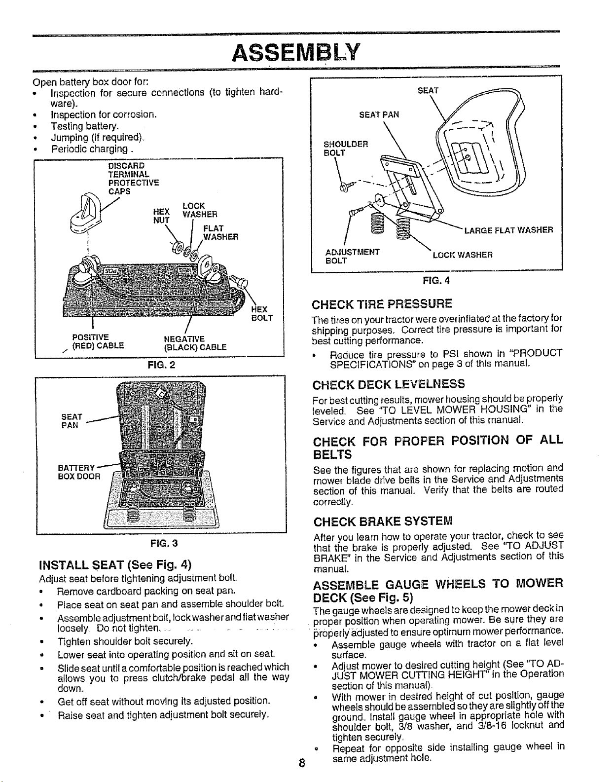
• Open battery box door and remove protective plastic,
° Remove terminal protective caps and discard_
• If this battery is put into service after month and year
indicated on label (label located between terminals)
charge battery for minimum of one hour at 6-10 amps,
° First connect RED battery cable to positive (+)terminal
with hex bolt, flat washer, lock washer and hex nut as
shown. Tighten securely.
• Connect BLACK grounding cable to negative (-) termi-
nal with remaining hex bolt, flat washer, lock washer'
and hex nut° Tighten securely.
Close battery box door.
STEERING
EXTENSION
SHAFT
5tl 6 HEX BOLT
FIG. 1
ASSEMBLY
...... ,,,.,,
Open battery box door for':
• Inspection for secure connections (to tighten hard-
ware).
• inspection for corrosion.
• Testing battery.
• Jumping (if required).
• Periodic charging.
DISCARD
TERMINAL
PROTECTIVE
LOCK
_ CAPS
i
i
WASHER
FLAT
WASHER
SEAT
SEAT PAN
SHOULDER
BOLT
LARGE FLAT WASHER
ADJUSTMENT LOCK WASHER
BOLT
FIG. 4
CHECK TiRE PRESSURE
The tires on your tractor were overinflated at the factory for
shipping purposes_ Correct tire pressure is important for
best cutting performance.
= Reduce tire pressure to PSI shown in "PRODUCT
SPECIFICATIONS" on page 3 of this manual.
POSITIVE
/ (RED) CABLE
HEX
BOLT
NEGATIVE
(BLACK)CABLE
FIG, 2
CHECK DECK LEVELNESS
For best cutting results, mower housing should be properly
SEAT
PAN
leveled. See "TO LEVEL MOWER HOUSING" in the
Service and Adjustments section of this manual
CHECK FOR PROPER POSITION OF ALL
BELTS
BATTEI
BOXDOOR
FIG, 3
INSTALL SEAT (See Fig. 4)
Adjust seat before tightening adjustment bolt,,
. Remove cardboard packing on seat pan.
• Place seat on seat pan and assemble shoulder bolt.
Assemble adjustment boit, lock washer and flat washer ...... ,= .... e- -re
loosely Do not tiahten proper' posmon when opera_mg moW_to _e sure m y a
• Tighten shoulder' bolt securely.
"' " ..................... pr0per'lyadjusted to ensure optimum mower •performance.
o Lower seat into operating position and sit on seat°
• Slide seat until a comfortable position isreached which
allows you to press clutch!brake pedal all the way
down.
• Get off seat without moving its adjusted position.
• Raise seat and tighten adjustment bolt securely.
See the figures that are shown for replacing motion and
mower blade drive belts in the Service and Adjustments
section of this manual Verify that the belts are routed
correctly.
CHECK BRAKE SYSTEM
After you learn how to operate your tractor, check to see
that the brake is properly adjusted_ See "TO ADJUST
BRAKE" in the Service and Adjustments section of this
manual,
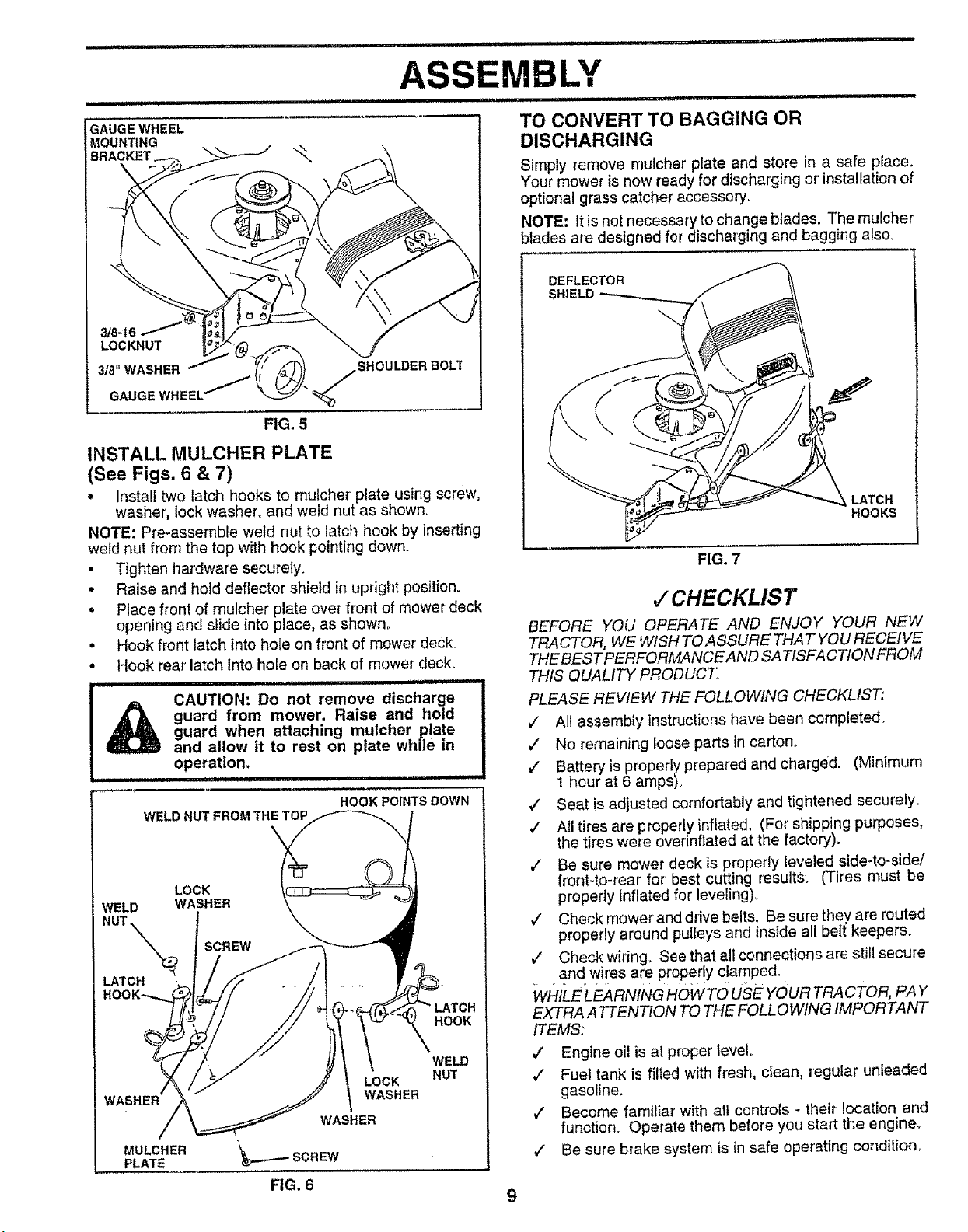
ASSEMBLE GAUGE WHEELS TO MOWER
DECK (See Fig. 5)
The gauge wheels are designed to keep the mower deck in
• Assemble gauge wheels with tractor on a flat level
surface.
° Adjust mower to desired cutting height (See "TO AD-
JUST MOWER CUTTING HEIGHT' in the Operation
section of this manual).
° With mower in desired height of cut position, gauge
wheels should be assembled so they are slightly off the
ground. Install gauge wheel in appropriate hole with
shoulder bolt, 3/8 washer, and 3/8-16 locknut and
tighten securelyo
Repeat for opposite side installing gauge wheel in
8
same adjustment hole.
ii =l=lll_ = ......... i= i lUlH .................... ='"="='
ASSEMBLY
ii ii IIIIIIIIIIIIHIII III q
GAUGE WHEEL
MOUNTING
BRACKET
3/8-16
LOCKNUT
318" WASHER jSHOULDER BOLl'
GAUGEWHEEL" "%
FIG, 5
INSTALL MULCHER PLATE
(See Figs. 6 & 7)
• Install two latch hooks to mulcher plate using screw,
washer, lock washer, and weld nut as shown.
NOTE: Pro-assemble weld nut to latch hook by inserting
weld nut from the top with hook pointing down.
• Tighten hardware securely.
• Raise and hold deflector shield in upright position.
• Place front of mulcher plate over front of mower deck
opening and slide into place, as shown
• Hook front latch into hole on front of mower deck_
• Hook rear latch into hole on back of mower deck.
i i i ,i ,i i,i1,1,1,111111 ii iiii i iiiiii
guard from mower. Raise and hold
guard when attaching mulcher plate
CAUTION: Do not remove discharge
and allow it to rest on plate while in
='1 M=
WELD
LATCH
WASHER
MULCHER
PLATE
operation,
WELD NUT FROM TH_
_...---_SCREW
FIG. 6
,, i iii iiiiil!l!lll iiii iiiii
HOOKPOINTSDOWN
LOCK
WASHER
WASHER
HOOK
WELD
NUT
9
iiii miNI, m NI, .......................II
TO CONVERT TO BAGGING OR
DISCHARGING
Simply remove mulcher plate and store in a safe place.
Your mower is now ready for discharging or installation of
optional grass catcher accessory.
NOTE: it is not necessary to change blades The mutcher
blades are designed for discharging and bagging also.
DEFLECTOR
FIG. 7
,/CHECKLIS T
BEFORE YOU OPERATE AND ENJOY YOUR NEW
TRACTOR, WE WISH TOASSURE THAT YOU RECEIVE
THEBES TPERFORMANCE AND SA TISFA C TION FROM
THIS QUALITY PRODUCT.
PLEASE REVIEW THE FOLLOWING CHECKLIST,
,/ All assembly instructions have been completed.
,/" No remainJng loose parts in carton.
,/ Batteryis property prepared and charged. (Minimum
t hour at 6 amps).
7 Seat is adjusted comfortably and tightened securely.
,/ All tires are properly inflated. (For shipping purposes,
the tires were ovennflated at the factory).
,/ Be sure mower deck is properly leveled side-to-side/
front-to-rear for best cutting resultS: (Tires must be
properly inflated for leveling).
,/ Check mowerand drive belts. Be sure they are routed
properly around pulleys and inside all belt keepers.
,/ Check wiring_ See that all connections are still secure
.... and wires are properly clamped.
WHILE LEA RN/NG NO WTO use YOUR TRACTOR, PAY
EXTRA ATTENTION TO THE FOLLOWING IMPORTANT
ITEMS:
,/ Engine oil is at proper level°
,/ Fuel tank is filled with fresh, clean, regular unleaded
gasoline.
v" Become familiar with atl controls - their location and
function. Operate them before you start the engine.
v" Be sure brake system is in safe operating condition.
LATCH
HOOKS
i, . . .................. _ u . nl i¸ ' i n ii, u i,i ......... ,,- ,,. ., .... _ _.".i=, ...... =,, n
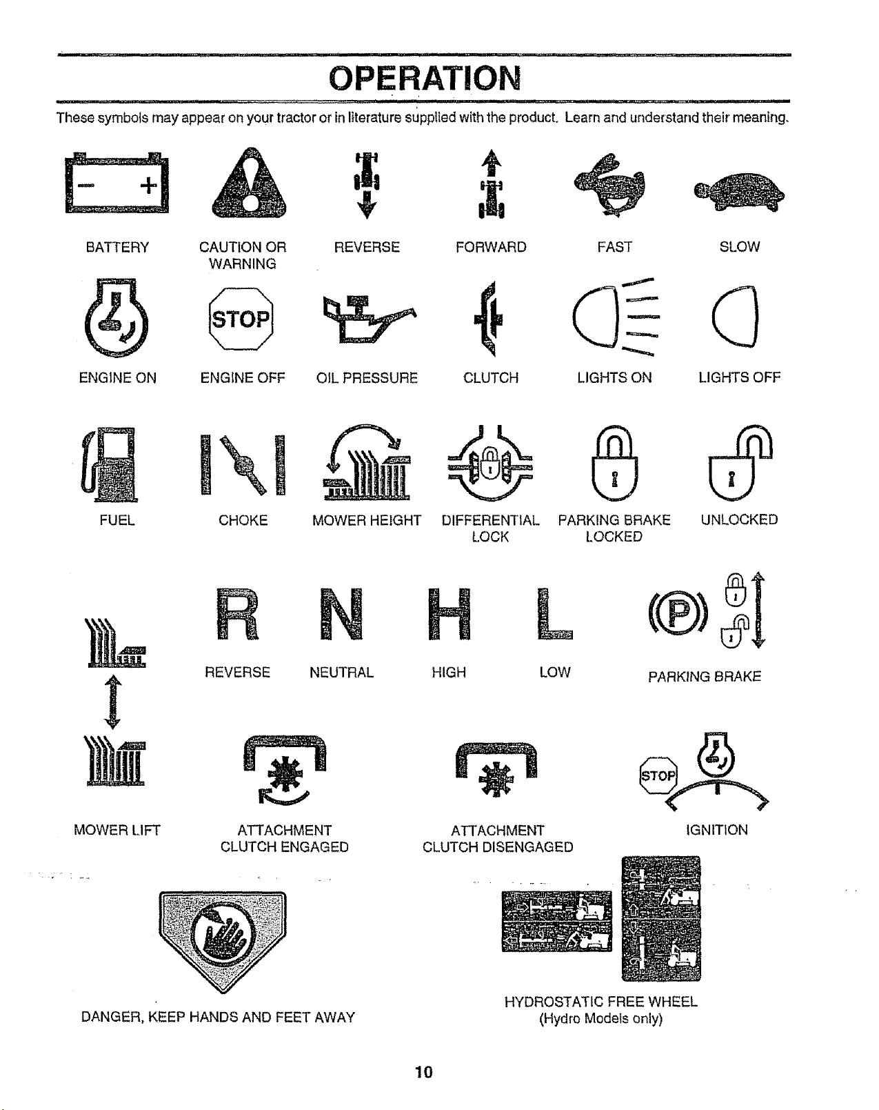
OPERATION
These symbols may appear on your tractor or inliterature sLtppUedwith the product. Learn and understand their meaning,
÷
BATTERY CAUTION OR REVERSE FORWARD FAST SLOW
WARNING
ENGINE ON ENGINE OFF OIL PRESSURE CLUTCH LIGHTS ON LIGHTS OFF
FUEL CHOKE MOWER HEIGHT UNLOCKEDDIFFERENTIAL PARKING BRAKE
LOCK LOCKED
L
MOWERLI_
REVERSE NEUTRAL HIGH
ATTACHMENT
CLUTCH ENGAGED
ATTACHMENT
CLUTCH DISENGAGED
LOW PARKING BRAKE
IGNITION
DANGER, KEEP HANDSANDFEETAWAY
HYDROSTATIC FREE WHEEL
(Hydro Models only)
10
=li== illll=i=ii,i ii i I==IH i, =ll, H ill
OPERATION
ijj I!ll iii iiiiiiiiii i i ii II iiii
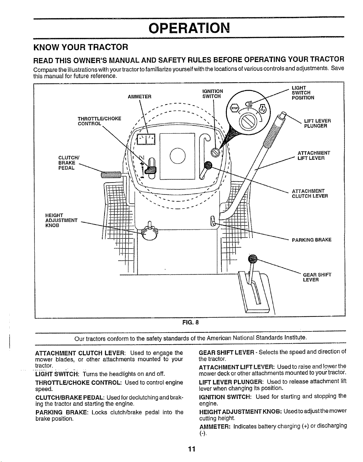
KNOW YOUR TRACTOR
READ THIS OWNER'S MANUAL AND SAFETY RULES BEFORE OPERATING YOUR TRACTOR
Compare the illustrationswith your tractor to familiarize yourself with the locations ofvarious controls and adjustments. Save
this manual for future reference.
CLUTCH/
BRAKE
PEDAL
HEIGHT
ADJUSTMENT
KNOB
THROTTL_CHOKE
CONTROL
AMMETER SWITCH POSITION
IGNITIO N SWtTC H
©
LIGHT
LIFT LEVER
PLUNGER
ATTACHMENT
LIFT LEVER
ATTACHMENT
CLUTCH LEVER
PARKING BRAKE
Our tractors conform to the safety standards of the American National Standards Institute.
ATTACHMENT CLUTCH LEVER: Used to engage the
mower blades, or other attachments mounted to your'
tractor.
LIGHT SWITCH: Turns the headlights on and off.
THROTTLE/CHOKE CONTROL: Used to control engine
speed.
CLUTCH/BRAKE PEDAL: Used for declutching and brak-
ingthe tractor and starting the engine.
PARKING BRAKE: Locks ctutch,_rake pedal into the
brake position_
GEARSHIFT
LEVER
FIG. 8
GEAR SHIFT LEVER - Selects the speed arid direction of
the tractor_
ATTACHMENT LIFT LEVER: Used to raise and lower the
mower deck or other' attachments mounted to yourtractor,.
LIFT LEVER PLUNGER: Used to release attachment lift
lever when changing its position.
IGNITION SWITCH: Used for starting and stopping the
engine,
HEIGHT ADJUSTMENT KNOB; Used to adjust the mower
cutting height,
AMMETER: Indicates battery charging (+) or discharging
(-)_
11
OPERATION
The operation of any tractor can result in foreign object s thrown into the eyes, which can
I _ ,_u== ] resultin severeeyedamage. Alwayswearsafetyglassesoreyeshieldswhile operatingyour
I _ tractor or performing any adjustments or repairs, We recommend a wide vision safety mask
I _ over the spectacles or standard safety glasses.
HOW TO USE YOUR TRACTOR
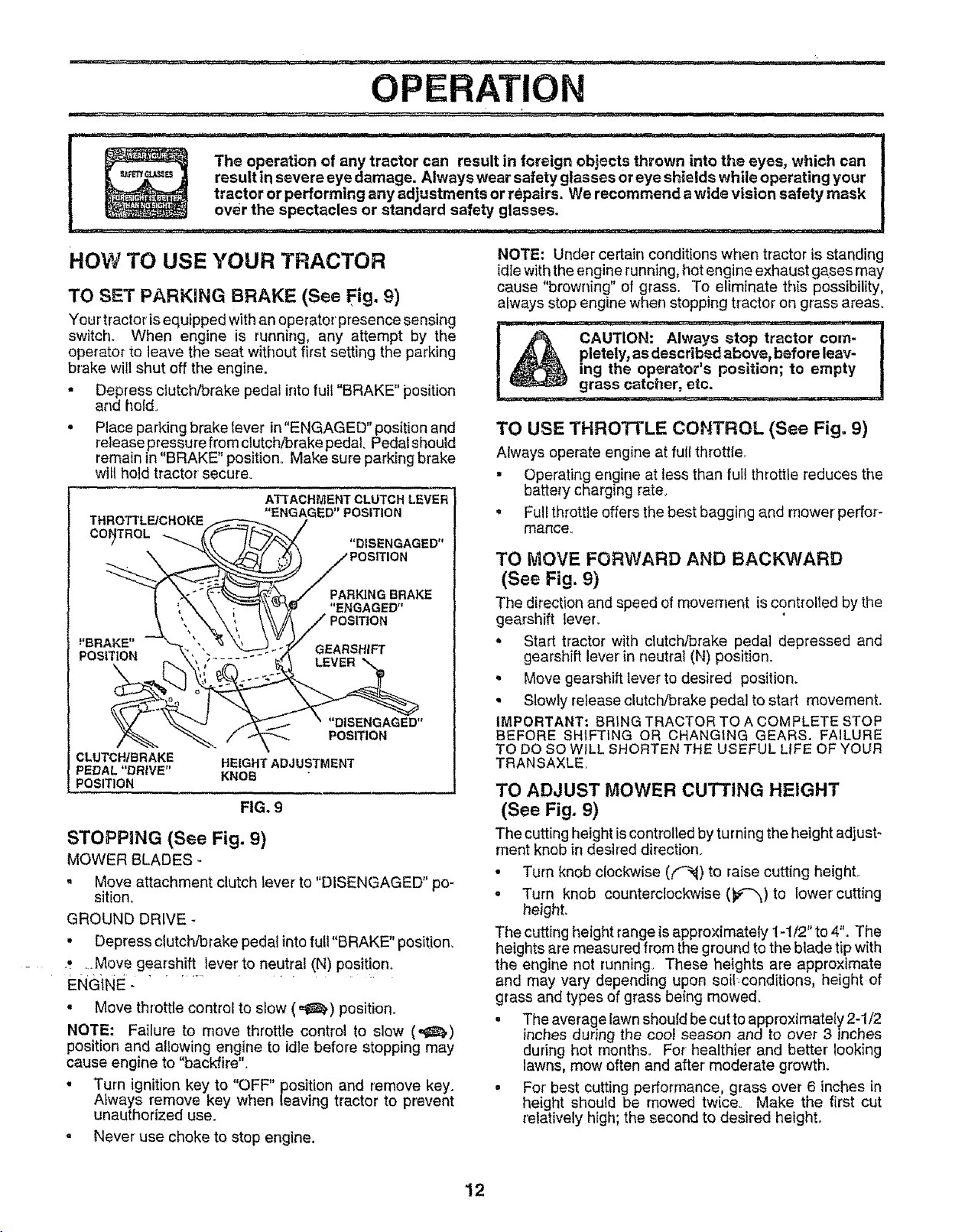
TO SET PARKING BRAKE (See Fig. 9)
Your'tractor'isequipped with an operator presence sensing
switch. When engine is running, any attempt by the
operator to leave the seat without first setting the parking
brake willshut off the engine.
• Depress clutch/brake pedal intofull "BRAKE" position
and hold_
* Place parking brake tever in"ENGAGED" position and
release pressure from clutch/brake pedaL Pedal should
remain in "BRAKE" position° Make sure parking brake
wilt hold tractor secure°
ATTACHMENT CLUTCH LEVER
THROTTLE/CHOKE
COI_TROL
_'BRAKE" GEARSHIFT
POS_ION
CLUTCH/BRAKE HEIGHT ADJUSTMENT
PEDAL "DRIVE" KNOB
POSITION
STOPPING (See Fig. 9)
MOWER BLADES -
• Move attachment clutch lever to "DISENGAGED" po-
sition.
GROUND DRIVE *
, Depress clutch/brake pedal into fuII"BRAKE" position.
_ _ :.Mov e gearshift _lever to neutral (N) posit!0n_
ENGINE -
• Move throttle control to slow (=l_) position.
NOTE: Failure to move throttle control to slow (,_,)
position and allowing engine to idle before stopping may
cause engine to "backfire".
• Turn ignition key to "OFF" position and remove key.
Always remove key when leaving tractor to prevent
unauthorized use.
, Never use choke to stop engine.
"ENGAGED" POSITION
PARKING BRAKE
"ENGAGED"
"DISENGAGED"
POS_ION
FIG. 9
NOTE: Under certain conditions when tractor is standing
idlewith the engine running, hot engine exhaust gases may
cause "browning" of grass. To eliminate this possibility,
always stop engine when stopping tractor on grass areas.
pletely, as described above, before leav-
CAUTION: Always stop tractor corn-
ing the operator's position; to empty
grass catcher, etc,
TO USE THROTrLE CONTROL (See Fig. 9)
Always operate engine at full thrott{e
• Operating engine at less than full throttle reduces the
battery charging rate.
, Full throttle offers the best bagging and mower perfor-
mance.
TO MOVE FORWARD AND BACKWARD
(See Fig. 9)
The direction and speed of movement is controlled by the
gearshift lever.
• Start tractor with dutch/brake pedal depressed and
gearshift lever in neutral (N) position.
• Move gearshift lever to desired position.
• Slowly release clutch/brake pedal to start movement.
IMPORTANT: BRING TRACTOR TO A COMPLETE STOP
BEFORE SHIFTING OR CHANGING GEARS. FAILURE
TO DO SO WILL SHORTEN THE USEFUL L{FE OF YOUR
TRANSAXLE
TO ADJUST MOWER CUTTING HEIGHT
(See Fig. 9)
The cutting height iscontrolled by turning the height adjust-
ment knob in desired direction.
• Turn knob c{ockwise ((_4) to raise cutting height,,
- Turn knob counterclockwise (_)to lower cutting
height.
The cutting height range is approximately ! -1/2" to 4". The
heights are measured from the ground to the blade tip with
the engine not running. These heights are approximate
and may vary depending upon soit conditions, height of
grass and types Of grass being mowed.
. The average lawn should be cutto approximately 2-1/2
inches during the cool season and to over 3 inches
dudng hot months. For healthier and better looking
lawns, mow often and after' moderate growth.
• For' best cutting performance, grass over 6 inches in
height should be mowed twice. Make the first cut
relatively high; the second to desired height,
12
L I ii ,11MI N, =::_ ::_ .................,1 ,..... =_
OPERATION
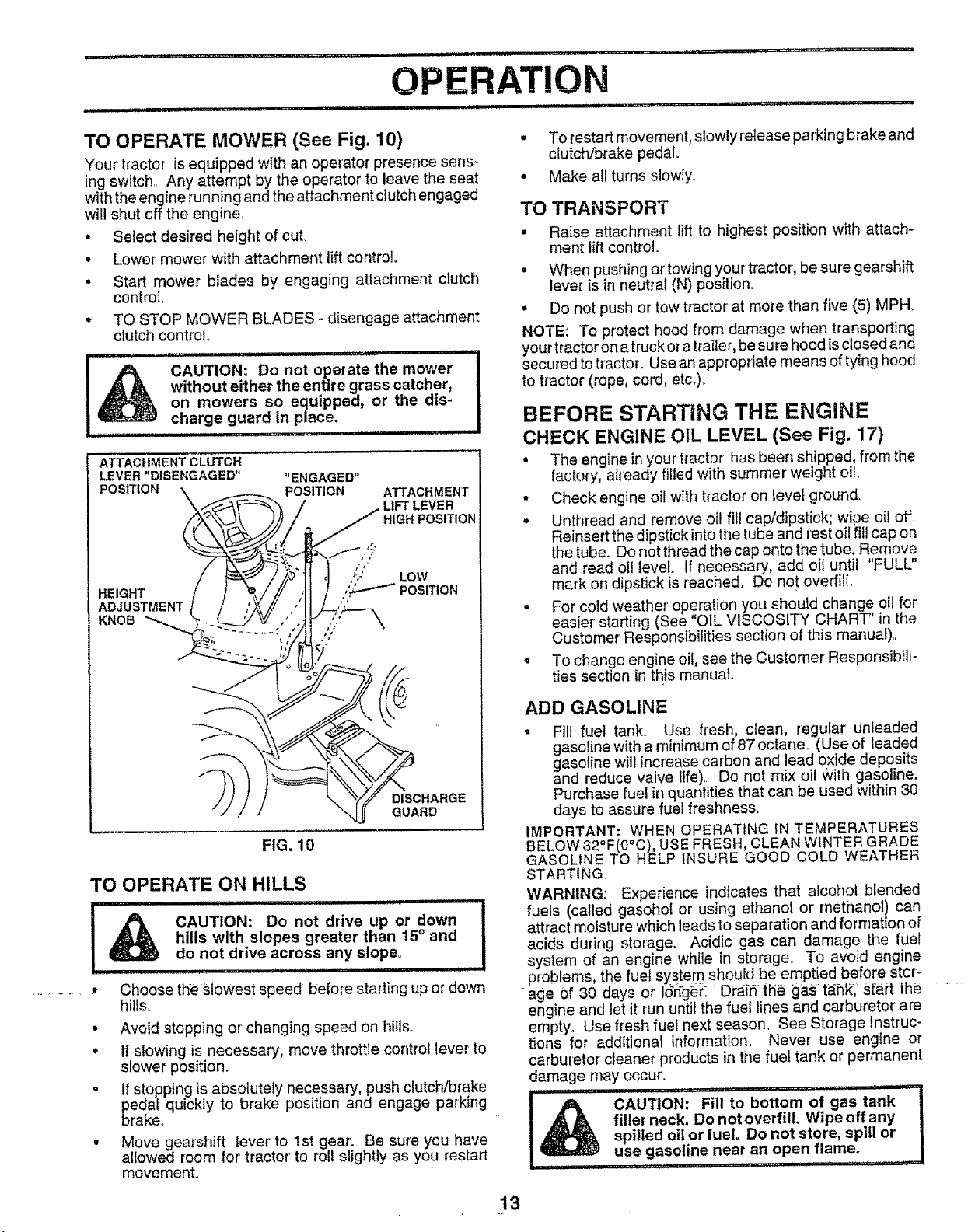
TO OPERATE MOWER (See Fig. 10)
Your'tractor [s equipped with an operator presence sens-
ing switch, Any attempt by the operator to leave the seat
with the engine running and the attachment clutch engaged
will shut off the engine.
* Select desired height of cuL
o Lower mower with attachment lift control.
. Start mower blades by engaging attachment clutch
control.
o TO STOP MOWER BLADES- disengage attachment
crutch control.
=ll L ii ....................................... ,, ii ii
without either the entire grass catcher,
CAUTION: Do not operate the mower
on mowers so equipped, or the dis-
charge guard in place.
,11 iiii iiu i
ATTACHMENT CLUTCH
LEVER "DISENGAGED" "ENGAGED"
POSITION \ _ POSITION ATTACHMENT
_/_ _._/ i_ HIGH POSITION
ADJUSTMENT t r /k_// ,/ ! /''
• To restart movement, slowly release parking brake and
clutch/brake pedal.
• Make all turns slowly_
TO TRANSPORT
o Raise attachment lift to highest position with attach-
ment lift control.
• When pushing or towing your tractor, be sure gearshift
lever is in neutral iN) position°
• Do not push or tow tractor at more than five (5) MPH_
NOTE: To protect hood from damage when transporting
your tractoron atruck oratrailer, be su re hood is closed and
secured to tractoL Use an appropriate means of tying hood
to tractor (rope, cord, etc.).
BEFORE STARTING THE ENGINE
CHECK ENGINE OIL LEVEL (See Fig. 17)
• The engine in your tractor has been shipped, from the
factory, already filled with summer weight oil..
- Check engine oil with tractor on level ground°
• Unthread and remove oil fill cap/dipstick; wipe oil off.
Reinsert the dipstick intothe tube and rest oil fill cap on
the tube. Do not thread the cap onto the tube. Remove
and read oil level if necessary, add oil until "FULL"
mark on dipstick is reached. Do not overfill
. For cold weather operation you should change oil for
easier' starting (See OiL VISCOSITY CHART' in the
Customer Responsibilities section of this manual),
• To change engine oil, see the Customer Responsibili-
ties section in this manual.
/ I _ GUARD
FIG. 10
TO OPERATE ON HILLS
ii i ml,l,i ,iH i,l,,,i,t ii,,N,N Nl'l
•i _#_ CAUTION: Do not drive up or down I
_ hills with slopes greater than 15° and
,,_ do not drive across any slope,
Ul, I ' I I H'H I ,,,,,,,,,,,,,,, ,,,,
...... _, - Choose the slowest speed before starting up or down
hills.
• Avoid stopping or changing speed on hills.
• If slowing is necessary, move throttle control lever to
slower position.
• If stopping is absolutely necessary, push clutch/brake
pedal quickly to brake position and engage parking
brake.,
• Move gearshift lever to 1st gear'. Be sure you have
aIIowed room for' tractor' to roll slightly as you restart
movement.
ADD GASOLINE
. Fill fuel tank_ Use fresh, clean, regular unleaded
gasoline with a minimum of 87 octane. (Useof leaded
gaso(ine will increase carbon and lead oxide deposits
and reduce valve life). Do not mix oil with gasoline.
Purchase fuel in quantities that can be used within 30
days to assure fuel freshness,
IMPORTANT: WHEN OPERATING IN TEMPERATURES
BELOW 32°F(0°C), USE FRESH, CLEAN WINTER GRADE
GASOLINE TO HELP INSURE GOOD COLD WEATHER
STARTING.
WARNING: Experience indicates that alcohol blended
fuels (called gasohot or using ethanol or methanol) can
attract moisture which leads to separation and formation of
acids during storage. Acidic gas can damage the fuel
I
system of an engine while in storage. To avoid engine
problems, the fuel system should be emptied before stor-
•age 0f 30 days or Idrtger. ' Di'a:[_ the _tas ta;nk;st-art the
engine and let it run untit the fuel lines and carburetor are
empty. Use fresh fuel next season. See Storage Instruc-
tions for addit]onat information. Never use engine or
carburetor cleaner products in the fuet tank or permanent
damage may occur.
'NI t HI", i ..... ,_ i
filler neck. Do not overfill Wipe off any
i_ AUTION: Fill to bottom of gas tank
................ I,=H i i ' =...............
spilled oil or fuel Do not store, spill or
use gasoline near an open flame.
13
OPERATION
TO START ENGINE (See Fig. X)
When starting the engine for the first time or' if the engine
has run out of fuel, it willtake extra cranking time to move
fuel from the tank to the engine.
• Sit on seat in operating position, depress clutch/brake
pedal and set parking brake.
• Place gear' shift lever in neutral iN) position.
• Move attachment clutch to "DISENGAGED" position.
• Move throttle control to choke iN) position°
Note: Before starting, feed the warm and cold starting
procedures below.
• Insert key intoignition and turn key clockwise to"START"
position and release key as soon as engine starts° Do
not run starter continuously for more than fifteen sec-
onds per minute_ If the engine does not start after
several attempts, move throttle control to fast (,f_)
position, wait a few minutes and try again. If engine still
does not start, move the throttle control back to the
choke iN) position and retry.
WARM WEATHER STARTING (50° F and above)
= When engine starts, move the throttle controlto the fast
(,t_) position.
. Th/aattachments and ground drive can now be used. If
the engine does not accept the load, restart the engine
and allow it to warm up for one minute using the choke
as described above.
COLD WEATHER STARTING ( 504 F and below)
• When engine starts, allow engine to run with the throttle
control in the choke (XI) position until the engine runs
roughly, then move throttle control to fast (.tl_) position,,
This may require an engine warm-up period from
several seconds to several minutes, depending on the
temperature.
• The attachments can also be used during the engine
warm-up period°
NOTE: If at a high altitude (above 3000 feet) or in cold
temperatures (below 32 F) the carburetor fuel mixture may
need to be adjusted for'best engine performance. See "TO
ADJUST CARBURETOR" in the Service and Adjustments
section of this manual..
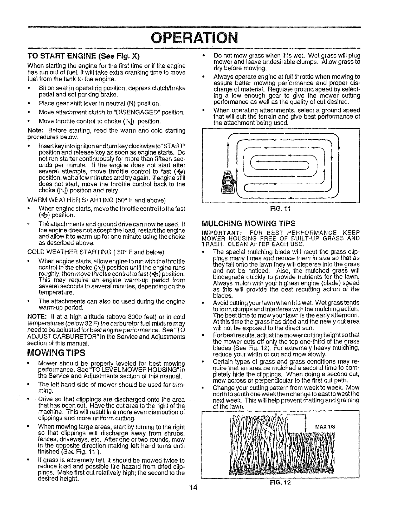
MOWING TIPS
• Mower should be ,properly leveled for best mowing
performance. See TO LEVELMOWER HOUSING" in
the Service and Adjustments section of this manual.
• The left hand side of mower' should be used for trim-
ming.
.. Ddve so that clippings are discharged onto the aFea
that has been cut. Have the cut area to the right of the
machine. This wilt result in a more even distribution of
clippings and more uniform cutting_
• When mowing large areas, start by turning to the right
so that clippings will discharge away from shrubs,
fences, driveways, etc. After one or two rounds, mow
in the opposite direction making left hand turns until
finished (See Fig. 11 ),,
- If grass is extremely tall, it should be mowed twice to
reduce load and possible fire hazard from dried clip-
pings. Make first cut relatively high; the second to the
desired height,.
• Do not mow grass when it is wet. Wet grass will plug
mower and leave undesirable clumps. Allow grass to
dry before mowing.
• Always operate engine at full throttle when mowing to
assure better mowing performance and proper dis-
charge of material., Regulate ground speed by select-
ing a low enough gear' to give the mower cutting
performance as wetl as the quality of cut desired.
• When operating attachments seiect a ground speed
that wilt suit the terrain and g ve best performance of
the attachment being used.
f
it(
FIG, 11
MULCHING MOWING TiPS
IMPORTANT: FOR BEST PERFORMANCE, KEEP
MOWER HOUSING FREE OF BUILT-UP GRASS AND
TRASH. CLEAN AFTER EACH USE.
• The special mulching blade wilt recut the glass clip-
pings many times and reduce them in size so that as
they fall onto the lawn they will disperse into the grass
and not be notice& Also, the mulched grass will
biodegrade quickly to provide nutrients for the lawn.
Always mulch with your' highest engine (blade) speed
as this will provide the best recurring action of the
blades.
• Avoid cutting your lawn whenit iswet. Wet grasstends
to form ctumps and interferes with the mulching action.,
The best time to mow your' lawn is the early afternoon,,
At this time the grass has dried and the newly cut area
will not be exposed to the direct sun,
• For best results, adjust the mower cutting height so that
the mower cuts off only the top one-third of the grass
blades (See Fig. 12). For extremely heavy mulching,
reduce your width of cut and mow slowly.
• Certain types of grass and grass conditions may re-
quire that an area be mulched a second time to com-
pletely hide the clippings,. When doing a second cut,
mow across or perpendicular to the first cut path.
• Change your cutting pattern from week to week. Mow
north to south one week then change to east to west the
nex_waek_ This willhelp prevent matting and graining
of the lawn.
MAX 1/3
FIG, 12
14
i,,u,,,i, i u,,i,,_lqqllll i i in'ill ¸ ' i iii u i i
CUSTOMER RESPONSIBILITIES
inunllUUl i lU i i i i ...........................................................
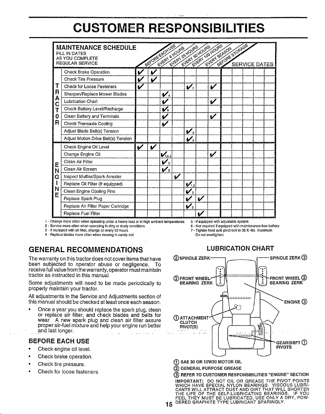
MA,NTENANCESC.EDuLE.....
F,LL,NDATES -
ASYOUCOMPLETE
CheckBrakeOperation I_
CheckTire Pressure ,,
T Checkfor LooseFasteners If
i i Sharpen/Rep lace Mower Btades 1_4
LubricationChart Irl/ V _
T Check Battery LeveVRecharge , V_
0 ,,C_eanBa_e_andTerminal. !V' V'
R Check Transaxle Cooling V _
Adjust Blade Belt(s) Tension
Adjust Motion Drive Belt(s) Tension
Check Engine Oil Level
ChangeEngineOit
CleanAirFiller
E
N ,CleanAir screen
G Inspect MuffledSparkArrester
I Replace Oil Fijter (If equipped)
CleanEngine Cooling Fins
ReplaceSparkPIug
Replace Air FilterPaper Cartridge
ReplaceFuelFiite{
t ..Change mote ellen when operating under a heavy load ot in high ambient temperatures
2 o Service more often when operating in dirty or dusty conditions
3 .. Ifequipped with oil filter, change oitevery 50 hours
4. Replace b)ades more eltan when mowing in sandy se()
v' v'
I
V#5
v',
v"_
v"
_2
VS
V' V'
6 - Not required Ifequipped with maintenance*free battery.
!v'
v'
5 - Ir equipped with adiustabie system
7 - Tlghlen front axle pivotbolt to 35 It-Ibs maximum
Do not evert{ghten
GENERAL RECOMMENDATIONS
The warranty on this tractor does not cover items that have
been subjected to operator' abuse or negligence. To
receive full value from the warranty, operator' must maintain
tractor as instructed in this manual,.
Some adjustments will need to be made periodically to
properIy maintain your' tractoL
All adjustments in the Service and Adjustments section of
this manual should be checked at least once each season.
• Once a year you should replace the spark plug, clean
or replace air filter, and check blades and belts for
wear. A new spark plug and clean air filter assure
proper' air-fuel mixture and help your engine run better
• and last longer. .......... -
BEFORE EACH USE
• Check engine oilteveL
• Check brake operation_
• Check tire pressure.
• Checkfor loose fasteners.
LUBRICATION CHART
®
_DLE ZERK (_)
FRONT WHEEL
BEARING ZERK
(_
CLUTCH
. P.IVOT(S)
PIVOTS
(_) SAE30OR10W30MOTOROIL
(_ GENERALPURPOSEGREASE
(3) REFERTOCUSTOMERRESPONSIBILITIES"ENGINE"SECTION
IMPORTANT: DO NOT OIL OR GREASE THE PIVOT POINTS
WHICHHAVE SPECIAL NYLONBEARINGS, VISCOUSLUBRI-
CANTSWiLL ATTRACTDUSTAND DIRTTHAT WILL SHORTEN
THE L(FE OF THE SELF-LUBRiCATING BEARINGS. IF YOU
FEELTHEY MUST BE LUBRICATED, USEONLY A DRY, POW-
15 DEREDGRAPHITETYPELUBRICANT SPARINGLY,
..=%
®
CUSTOMER RESPONSIBILiTiES
'IIIIN I.............................. ............. i II I IIIIIIIIIIIIIII................
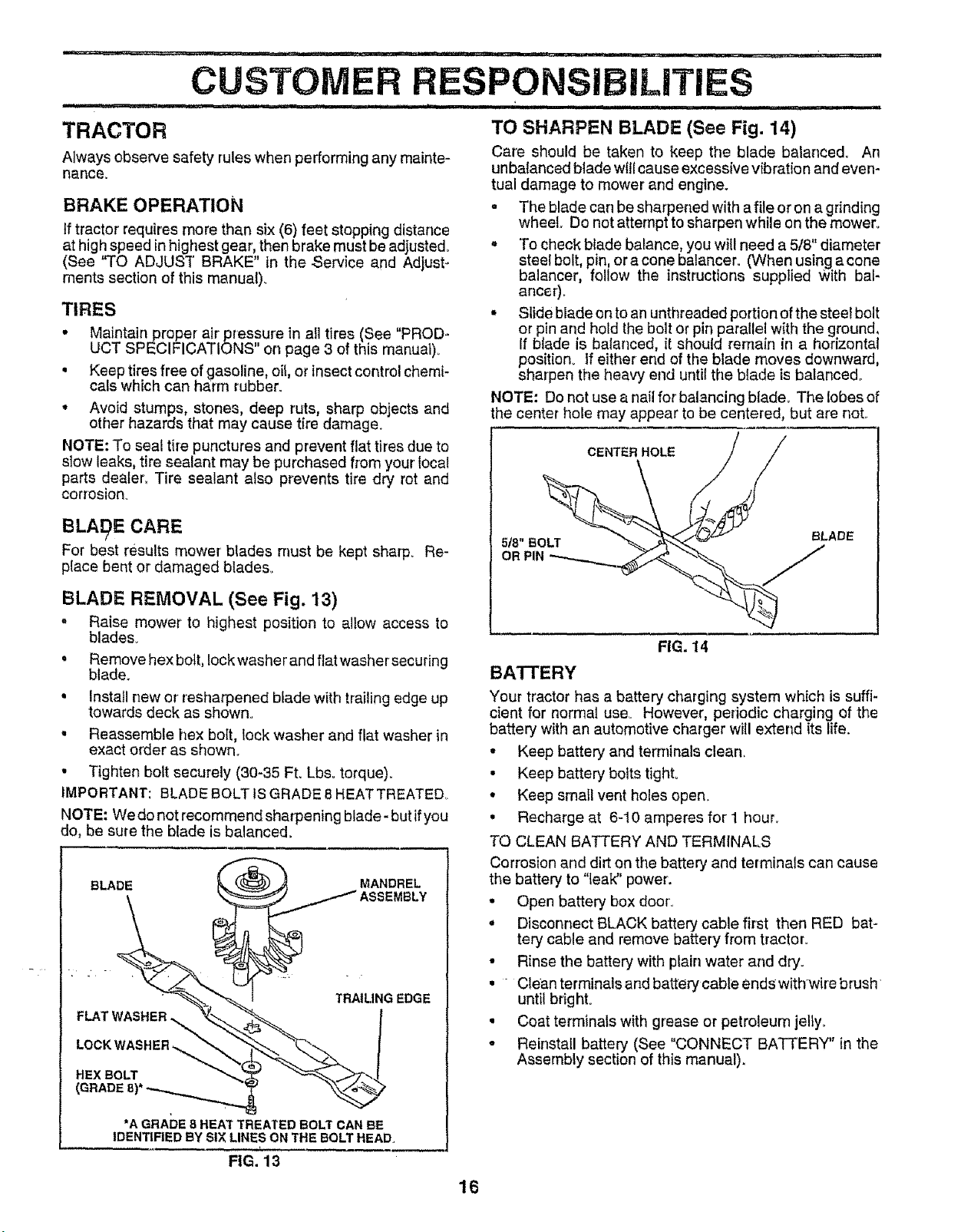
TRACTOR TO SHARPEN BLADE (See Fig. 14)
Always observe safety ruleswhen performing any mainte- Care should be taken to keep the blade balanced° An
nance, tual damage to mower and engine.
BRAKE OPERATION
tf tractor' requires more than six (6) feet stopping distance
at high speed in highest gear, then brake must be adjusted°
(See "TO ADJUST BRAKE" in the Service and Adjust-
ments section of this manual).
TIRES
• Maintainproper air pressure in all tires (See "PROD*
UCT SPECIFICATIONS on page 3 of this manual).
• Keep tires free ofgasoline, oil, or insect control chemi-
cals which can harm rubber.
• Avoid stumps, stones, deep ruts, sharp objects and
other hazards that may cause tire damage.
NOTE: To seal tire punctures and prevent flat tires due to
slow leaks, tire sealant may be purchased from your local
parts dealer, Tire sealant also prevents tire dry rot and
corrosion_
BLA£_E CARE
For best results mower blades must be kept sharp. Re-
place bent or damaged blades.
unbatanced blade willcause excessive vibration and even-
• The blade can be sharpened with a file or on a grinding
wheel. Do not attempt to sharpen while on the mower.
° To check blade balance, you will need a 5/8" diameter
steel bolt, pin, or a cone balancer. (When using a cone
balancer, follow the instructions supplied With bal-
ancer_.
• Slide blade on to an unthreaded portion of the steel bolt
or pin and hold the bolt or pin parallel with the ground,
If blade is balanced, it should remain in a horizontal
position_ If either end of the blade moves downward,
sharpen the heavy end until the blade is balanced..
NOTE: Do notuse a nail for balancing blade. The lobes of
the center hole may appear to be centered, but are noL
CENTER HOLE
518" BOLT
OR PIN
BLADE
BLADE REMOVAL (See Fig. 13)
. Raise mower to highest position to allow access to
blades_
• Remove hex bott, Iockwasher and flat washer securing
blade_
• Install new or resharpened blade with trailing edge up
towards deck as shown.
• Reassemble hex bolt, lock washer and flat washer in
exact order as shown°
• Tighten bolt securely (30-35 Ft. Lbs. torque).
IMPORTANT: BLADE BOLT tSGRADE 8 HEATTREATED.
NOTE: We do not recommend sharpening blade- but ifyou
do, be sure the blade is balanced.
EDGE
'
BATTERY
Your tractor has a battery charging system which is suffi-
cient for normal use° However, periodic charging of the
battery with an automotive charger wiil extend its life.
• Keep battery and terminals clean,
• Keep battery bolts tight.
• Keep small vent holes open.
, Recharge at 6-10 amperes for' 1 hour.
TO CLEAN BATTERY AND TERMINALS
Corrosion and dirt on the battery and terminals can cause
the battery to "leak" power.
• Open battery box door..
• Disconnect BLACK battery cable first then RED bat-
tery cable and remove battery from tractor°
• Rinse the battery with plain water and dry.
• Clean terminals and battery cable ends withwire brush
until bright°
• Coat terminals with grease or petroleum jelly.
• Reinstall battery (See "CONNECT BATTERY" in the
Assembly section of this manual).
FIG. 14
*A GRADE 8 HEAt" TREATED BOLT CAN EE
IDENTIFIED BY SIX LINES ON THE BOLT HEAD,
FIG. 13
16
i i .................................................... ,r,,-_- ........... , ii iiiiiiiii1,11111
CUSTOMER RESPONSIBILITIES
ii i i i iiiiiii iiiiiiii ii i i iii ii ii i
V-BELTS
Check V_beits for deterioration and wear after 100 hours of
operation arid replace if necessary. The baits are not
adjustable. Replace belts if they begin to slip from wear.
TRANSAXLE COOLING
Keep transaxle free from build-up of dirt and chaff which
can restrict cooling,
ENGINE
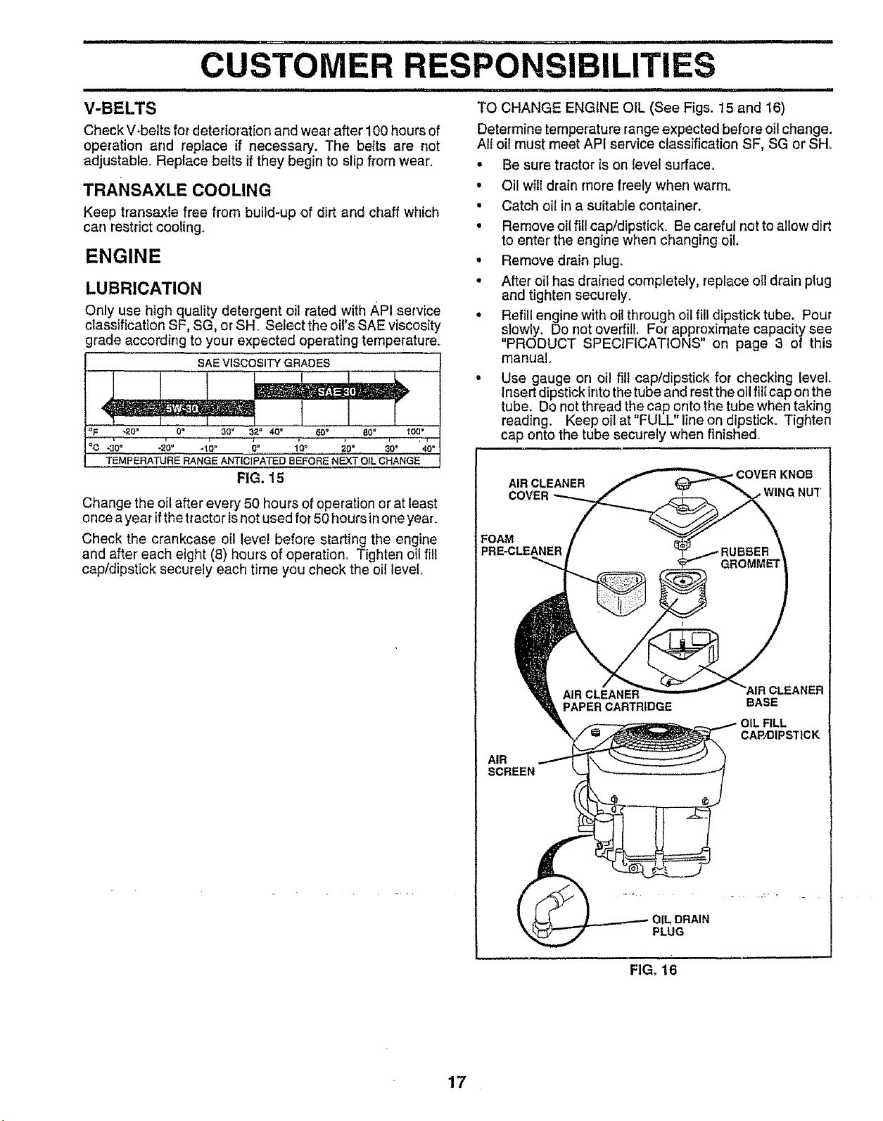
LUBRICATION
Only use high quality detergent oil rated with API service
classification SF, SG, orSH Select the oil's SAE viscosity
grade according to your expected operating tempe[ature.
SAE VISCOSITY GRADES
!
._ ' .2o° 0. _o, 3_o 40. .........60° S0• _oo°
°c-=o° . 'oo G° 1o, • 40"
TEMP ERATUR E RANGE ANTIC|PATED B EFORE N EXT O(L CHANGE
FIG, 15
Change the oil after every 50 hours of operation or at least
once a year if the tractor isnot used for 50 hours in one year.
Check the crankcase oil level before starting the engine
and after each eight (8) hours of operation. Tighten oil fill
cap/dipstick securely each time you check the oil level.
TO CHANGE ENGINE OIL (See Figs. 15 and 16)
Determine temperature range expected before oi! change.
All oil must meet API service classification SF, SG or SH,
° Be sure tractor is on (eve( surface.
• Oi! will drain more freely when warm.
° Catch oi! in a suitable container.
° Remove oil fill cap/dipstick. Be careful not to allow dirt
to enter' the engine when changing oil
• Remove drain plug.
• After oil has drained completely, replace oil drain ptug
and tighten securely,
• Refill engine with oil through oil fill dipstick tube. Pour
slowly. Do not overfill. For approximate capacity see
"PRODUCT SPECIFICATIONS" on page 3 of this
manual.
= Use gauge on oil fill cap/dipstick for checking level.
Insert dipstick intothe tube and rest the oil fill cap on the
tube. Do not thread the cap onto the tube when taking
reading. Keep oil at FULL line on dipstick° Tighten
cap onto the tube securely when finished.
AIR CLEANER
COVER ,WING NUT
FOAM
PRE-CLEANER
COVER KNOB
17
AIR
SCREEN
PAPER CARTRIDGE
FIG_ 16
AIR CLEANER
BASE
FILL
CAP'DIPST1CK
OIL DRAIN
PLUG
 Loading...