

Page 1

/ ROFTZ
MODEL M 917.258532 OWNER'S MANUAL
oAssembly
, Operation
° Customer Responsibilities
° Service and Adjustments
oRepair Parts
®
CAUTION: Read and follow all safety rules and instructions before operating this equipment.
FOR CONSUMER ASSISTANCE HOT LINE, CALL THIS TOLL FREE NUMBER: 1-800-659-5917
I! IIIIIIIIIIIIIIIIIIIII!!!1111111 HIIIIIIIIII ....
Page 2
Safe Operation Practices for Ride-On Mowers
IMPORTANT: THIS CUTTING MACHINE IS CAPABLE OF AMPUTATING HANDS AND FEET AND THROWING OBJECTS.
FAILURE TO OBSERVE THE FOLLOWING SAFETY INSTRUCTIONS COULD RESULT IN SERIOUS INJURY OR DEATH_
SAFETY RULES
I. GENERAL OPERATION
• Read, understand, and follow all instructions in the manual
and on the machine before starting
• Only allow responsible adults, who are familiar with the
instructions, to operate the machine.
• Clear the area of objects such as rocks, toys, wire, etc..,
which could be picked up and thrown by the blade.
• Besure the area isclear ofother people before mowing Stop
machine if anyone enters ti_e area.
• Never carry passengers.
• Do not mow tn reverse unless absolutely necessary. Always
look down and behind before and while backing_
• Be aware of the mower' discharge direction and do not point
it at anyone.. Do not operate the mower without either the
entire grass catcher or the guard in place.
• Slow down before turning.
,, Never reave a running machine unattended. Always turn off
blades, set parking brake, stop engine, and remove keys
before dismounting
• Turn off blades when not mowing.
• Stop engine before removing grass catcher or unclogging
chute..
• Mow only in daylight or good artificial light.
- Do net operate the machine while under the influence of
alcohol or drugs.
- Watch for traffic when operating near or crossing roadways..
° Use extra care when loading or unloading the machine into
a trailer or truck.
II. SLOPE OPERATION
Slopes are a major factor related to loss-of-control and
tipoveraccidents, which can result in severe injury or death,
All slopes require extra caution. If you cannot back up the
slope or if you feel uneasy on it, do not mow it,
DO:
• Mow up and down slopes, not across,
° Remove obstacles such as rocks, tree limbs, etc
° Watch for ho]es, ruts, or bumps. Uneven terrain could
overturn the machine Tall grass can hide obstacles.
• Use slow speed_ Choose a low gear so that you will not have
to stop or shift while on the slop&
• Follow the manufacturer's recommendations for wheel
weights or counterweights to improve stability.
• Use extra care with grass catchers or other attachments.
These can change the stability of the machine
• Keep all movement on the slopes slow and gradual Do not
make sudden changes in speed or direction.
° Avoid starling or stepping on a slope, if tires lose traction,
disengage the blades and proceed slowly straight down the
slope
DO NOT:
° Donot turn on slopes unless necessary, and then, turn s_owly
and gradually downhill, if possible.
• Do not mow near drop-ells, ditches, or embankment& The
mower could suddenly turn over if a wheel isover the edge
ofa cliff or ditch, or if an edge caves in,
° Do not mow on wet grass. Reduced traction could cause
sliding
° Do not trytostabilize the machine by puttingyour foot onthe
ground.
• Do not use grass catcher on steep slopes.
!il. CHILDREN
Tragic accidents can occur if the operator is not alert to the
presence of children_ Children are often attracted to the
machine and the mowing activity Never' assume that
children will remain where you last saw them.
• Keep childrenout ofthe mowing area and under thewatchful
care of another responsible adult.
• Be alert and turnmachine off if children enter the area.
• Before and when backing, took behind and down for small
children.
• Never carry chi_drenoThey may faU off and be seriously
injuredor interfere with safe machine operation.
• Never allow children tooperate the machine,
• Use extra care when approaching blind comers, shrubs,
trees, or other objectsthat may obscure vision°
IV. SERVICE
• Use extra care inhandiing gasoline and other fuels, They are
flammable and vapors are explosiv&
• Use only an approved container_
- Never remove gas cap or add fuel with the engine
running. Allow engine to cool before refueling_ Do not
smoke
Never refuel the machine indoors,
- Never store the machine or fuel container inside where
there is an open flame, such as awater heater,
° Never run a machine inside a closed area.
° Keep nuts and bolts, especially blade attachment bolts, tight
and keep equipment in good condition,
° Never tamper with safety devices, Check their proper
operation regularly,
° Keep machine free of grass, leaves, or other debris build_up.
Clean oil or fuel spillage, Allow machine to cool before
storing
• Stop "and inspect the equipment if you stdke an objecL
Repair, if necessary, before restarting
• Never make adjustments or repairs with the engine running,
° Grass catcher components are subject towear, damage, and
deterioration, which could expose moving parts or allow
objects to be thrown. Frequently check components and
replace with manufacturer's recommended parts, when nero
essary,
° Mower blades are sharp and can cuL Wrap the blade(s) or
wear gloves, and use extra caution when servicing them_
° Check brake operation frequently, Adjust and service as
required,
Look for this symbol to point out im-
porlant safety precautions, it means
CAUTION!!! BECOME ALERT!H YOUR
SAFETY IS INVOLVED.
CAUTION: Always disconnect spark plug
wire and place wirewhere it cannot contact
spark plug in order to prevent accidental
starting when setting up, transporting,
adjusting or making repairs°
i ii i ,i i ii ii=ll u= i =l=l=l=l=l=nnu=Hl=u
i ill ,llu ull i/u lull
& WARNING
The engine exhaust from this product con-
tains ctiemicals known to the State of Califor-
nia to cause cancer, birth defects, or other
reproductive harm.
,Jlu,/,lu
2
Page 3

CONGRATULATIONS on your purchase of a Sears
Tractor, It has been designed, engineered and manufac-
tured to give you the best possible dependability and
performance.
Should you experience any problem you cannot easily
remedy, please contact your nearest Sears Authorized
Service Center!Department. We have competent, well-
trained technicians and the proper tools to service or repair
this tractor_
Please read and retain this manual. The instructions will
enable you toassemble and maintain your tractor properly_,
Always observe the "SAFETY RULES".
MODEL
NUMBER 917°258532
SERIAL
NUMBER
DATEOFPURCHASE
TH EMODEL AND SERIAL NUMBERS WILL BE FOUND
ON A PLATE UNDER THE SEAT,
YOU SHOULD RECORD BOTH SERIAL NUMBER AND
DATE OF PURCHASE AND KEEP IN A SAFE PLACE
--ORFUTURE REFERENCE.
PRODUCT SPECIFICATIONS
HORSEPOWER: 15.5
GASOLINE CAPACITY t °25 GALLONS
AND TYPE: UNLEADED REGULAR
OIL TYPE (API-SF/SG/SH): SAE 30 (above 32°F)
SAE 5W-30 (below 32"F)
OIL CAPACITY: 30 PINTS
SPARK PLUG: CHAMPION RJ19LM
(GAP: .434")
VALVE CLEARANCE: INTAKE: ,1005"-.007"
EXHAUST: ,449" - .Oll"
GROUND SPEED (MPH): FORWARD: 4- 5,5
REVERSE: 4- 2,4
TIRE PRESSURE: FRONT: 14 PSI
REAR: 14 PSI
CHARGING SYSTEM: 3 AMPS BATTERY
5AMPS HEADLIGHTS
BATTERY: AMP/HR: 25
MINoCCA: 190
CASE SIZE: U1R
BLADE BOLT TORQUE: 30-35 FT_LBSo
MAINTENANCE AGREEMENT
A Sears Maintenance Agreement is available on this prod-
ucL Contact your nearest Sears store for details.
CUSTOMER RESPONSIBILITIES
• Read and observe the safety rufes.
° Fo!lowa regular schedule in maintaining, caring for and
using your tractor.,
. Follow the instructions under"Customer Responsibili-
ties" and "Storage" sections of this owner's manual.
WARNING: This tractor is equipped with an internal
combustion engine and should not be used on or nearany
unimproved forest-covered, brush-covered or grass-cov-
ered landunless the engine's exhaust system is equipped
with aspark arrester meeting applicable local or state laws
(if any), If a spark arrester is used, itshould be maintained
in effective working order by the operator,
In the state of California the above is required by law
(Section 4442 of the California Public Resources Code).
Other states may have similar lawso Federal laws apply on
federal lands. A spark arrester for the muffler is available
through your nearest Sears Authorized Service Center/
Department (See REPAIR PARTS section of thismanual).
LIMITED TWO YEAR WARRANTY ON CRAFTSMAN RIDING EQUIPMENT
For twe (2) years from the date ef purchase, if this Craftsman Riding Equipment is maintained, lubricated and tuned up according
to the instructionsin the owners manual, Sears will repair or replace, free of charge, any parts found to be defective in material or
workmanship,
This Warranty does not cover:
• Expendable items which become worn during normal use, such as blades, spark plugs, air cleaners, belts, etc.
• Tire replacement or repair caused by punctures from outside objects, such as nails, thorns, stumps, or glass.
• Repairs necessary because of operator abuse, negligence, improper storage or accident or the failure to maintain the
equipment according to the instructions contained in the owner's manual.
o Riding equipment used for commercial or rental purposes°
LIMITED 90 DAY WARRANTY ON BATTERY
For ninety (94) days from date of purchase, if any battery included with this riding equipment proves defective in material or
workmanship and our testing determines the battery will not hold acharge, Sears wilt replace the battery at no charge,.
IN.HOME WARRANTY SERVICE ON YOUR CRAFTSMAN RIDING EQUIPMENT IS AVAILABLE AT NO-CHARGE FOR 30
DAYS FROM THE DATE OF PURCHASE PLEASE CONTACT YOUR NEAREST SERVICE CENTER. AFTER 30 DAYS FROM
THE DATE OF PURCHASE, WARRANTY SERVICE IS AVAILABLE BY TAKING YOUR CRAFTSMAN RIDING EQUIPMENT TO
YOUR NEAREST SEARS SERVICE CENTER. (IN-HOME WARRANTY SERVICE WILL STILL BE AVAILABLE AFTER 30 DAYS
FROM THE DATE OF PURCHASE BUT A STANDARD TRIP CHARGE WILL APPLY.) THIS WARRANTY APPLIES ONLY
WHILE THIS PRODUCT IS IN THE UNITED STATES°
This Warranty gives you specific legal rights, and you may also have other rights which may vary from state te state.
SEARS, ROEBUCK AND CO.,, D/817 WA, HOFFMAN ESTATES, IL 60179
3
Page 4
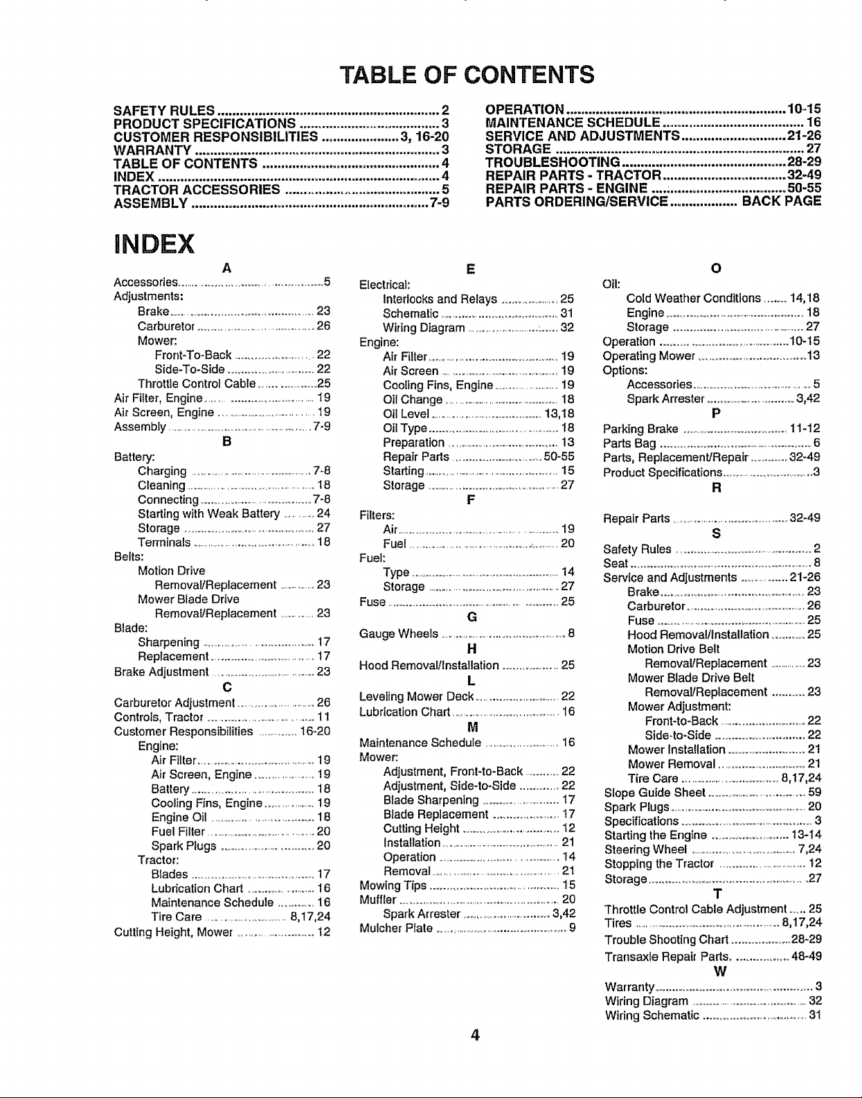
TABLE OF CONTENTS
SAFETY RULES ............................................................ 2
PRODUCT SPECIFICATIONS ...................................... 3
CUSTOMER RESPONSIBILITIES ..................... 3, 16-20
WARRANTY .................................................................. 3
TABLE OF CONTENTS ................................................ 4
INDEX ............................................................................ 4
TRACTOR ACCESSORIES .......................................... 5
ASSEMBLY ................................................................ 7-9
iNDEX
A
Accessories ...................................................5
Adjustments:
Brake ...............................................23
Carburetor ...................................... 26
Mower:.
Front-To-Back .............................22
Side-To-Side ...............................22
Throttle Control Cable .....................25
Air Filter, Engine .......................................19
Air Screen, Engine ..........................................19
Assembly .........................................................7-9
B
Battery:
Charging....................................................7-8
Cleaning .....................................................18
Connecting .......................................7-8
Starling with Weak Battery ...........24
Storage .......................................... 27
Terminals ..............................................18
Belts:
Motion Drive
Removal/Replacement .................23
Mower Blade Drive
Removal/Replacement ................23
Blade:
Sharpening ...........................................17
Replacement .......................................17
Brake Adjustment ........................................23
C
Carburetor Adjustment ..................................26
Controls, Tractor ......................................11
Customer Responsibilities ..................t6-20
Engine:
Air Filter ...............................................19
Air Screen, Engine ........................19
Battery ....................................... 18
Cooling Fins, Engine .......................19
Engine Oil .......................................18
Fuel Filter ...........................................20
Spark Plugs ....................................20
Tractor:
Blades ...........................................17
Lubrication Chad ........................16
Maintenance Schedule ........... 16
Tire Care ..............................8,!7,24
Cutting Height, Mower. ...........................12
Electrical:
Interlocks and Relays .....................25
Schematic ........................................31
Wiring Diagram .................................:.....32
Engine:
Air Filler..............................................19
Air Screen ......................................................19
Cooling Fins, Engine ................................19
Oil Change ...................................................18
Oil Level ................................................13,I8
Oil Type ............................................t8
Preparation ...........................................13
Repair Parts ..............................50-55
Starting ..................................................t5
Storage ..................................................27
Filters:
Air ...................................................................19
Fuel.............................................................20
Fuel:
Type ....................................................................14
Storage ...............................................27
Fuse ..................................................................25
Gauge Wheels ..............................................8
Hood Removal/installatien ....................25
Leveling Mower Deck ..............................22
Lubrication Chad ............................................16
Maintenance Schedule ...............................16
Mower:.
Adjustment, Front-to-Back ...........22
Adjustment, Side-to-Side ............ 22
Blade Sharpening ...........................17
Blade Replacement ........................17
Cutting Height ...................................12
Installation .......................................................21
Operation ................................................14
Removal .......................................................21
Mowing Tips............................................15
Muffler. ......................................................20
Spark Attester ..................................3,42
MulcherPlate....................................................9
OPERATION ........................................................... 1045
MAINTENANCE SCHEDULE ...................................... 16
SERVICE AND ADJUSTMENTS ............................ 2t-26
STORAGE ................................................................... 27
TROUBLESHOOTING ............................................ 28-29
REPAIR PARTS - TRACTOR ................................. 32-49
REPAIR PARTS - ENGINE .................................... 50-55
PARTS ORDERING/SERVICE .................. BACK PAGE
E
Oil:
Cold Weather Conditions .........14,18
Engine ...................................................18
Storage .................................................27
Operation ............................................10-t5
Operating Mower .....................................13
Options:
Accessories ...........................................5
Spark Arrester _..................................3,42
Parking Brake ...........................................t 1-12
Parts Bag .....................................................6
Parts, Replacement/Repair ...............32-49
Product Specifications ..........................................3
F
Repair Pads ..............................................32-49
Safety Rules ....................................................2
Seat .................................................................8
Service and Adjustments ...................21-26
Brake ...............................................23
G
H
L
M
Carburetor ...................................................26
Fuse .................................................................25
Hood Removal/InstaUation..........25
MotionDriveBelt
Removal/Replacement ................23
Mower Blade Drive Belt
Removal/Replacement .......... 23
Mower Adjustment:
Front-to-Back ................................22
Side4o-Side ............................22
Mower installation ...........................21
Mower Removal .................................21
Tire Care .....................................8,17,24
Slope Guide Sheet .....................................59
Spark Plugs .....................................................20
Specifications ........................................... ...... 3
Starling the Engine ..........................13-14
Steering Wheel ......................................7,24
Stopping the Tractor ....................................12
Storage .........................................................27
0
P
R
S
T
Throttie Control Cable Adjustment .....25
Tires .............................................................8,17,24
Trouble Shooting Chad ....................28-29
Transaxle Repair Pads ................. 48-49
W
Warranty...................................................3
Wiring Diagram ........................................32
Wiring Schematic ......................................31
4
Page 5
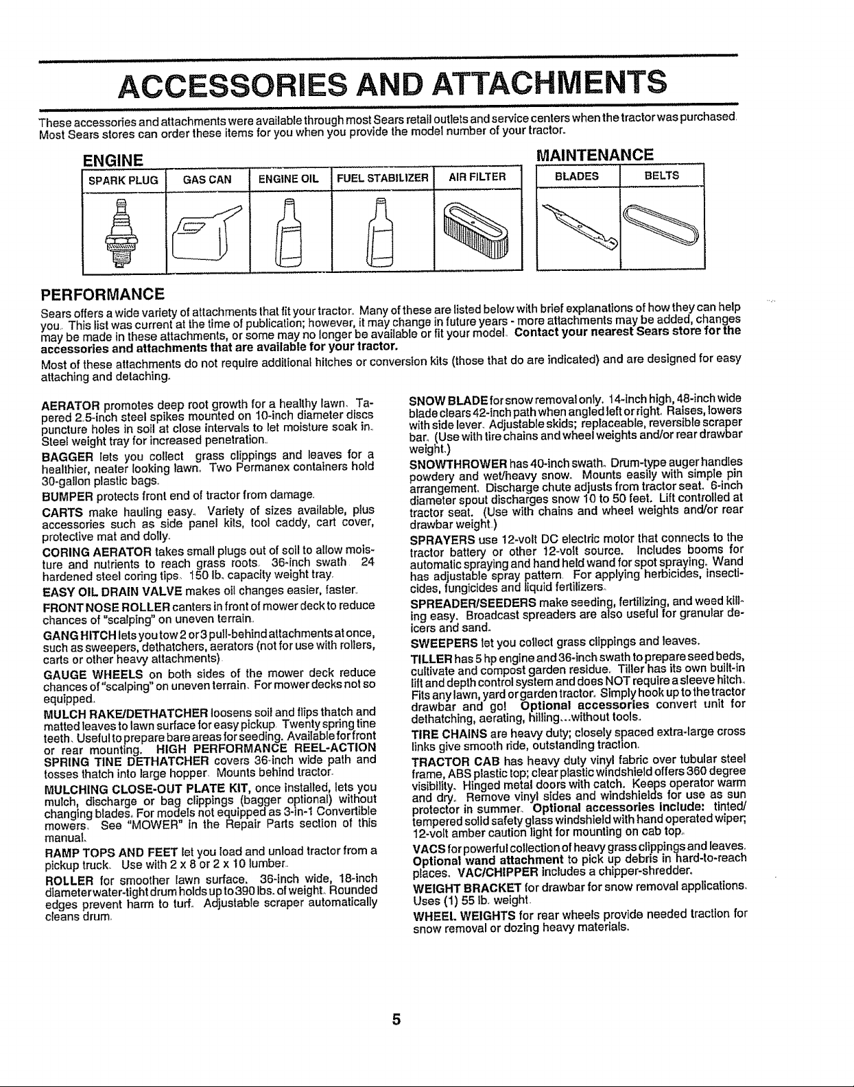
AND ATTACHM
These accessodes and attachments were available throughmost Sears retail outlets and service centers whenthe tractorwas purchased
Most Sears stores can order these items for you when you provide the model number of your tractor.
ENGIN E MAINTENANCE
GASCAN ENGINEOIL FUELSTABILIZER
PERFORMANCE
Sears offers a widevariety of attachmentsthat fityour tractor. Many ofthese are listed below with brief explanationsofhow theycan help
you This list was current at the time of publication; however, it may change in future years - more attachments may be added, changes
may be made in these attachments, or some may no longer be available or fit yourmodel. Contact your nearest Sears store for the
accessories and attachments that are available for your tractor.
Most of these attachments do not require additional hitches or conversion kits (those that do are indicated) and are designed for easy
attaching and detaching.
AERATOR promotes deep root growth for a healthy lawn. Ta-
pered 25-inch steel spikes mounted on 10-inch diameter discs
puncture holes in soil at close intervals to let moisture soak in.
Steel weight tray for increased penetration..
BAGGER lets you collect grass clippings and leaves for a
healthier, nealer looking lawn. Two Permane× containers hold
30-gallon plastic bags.
BUMPER protects front end of tractor from damage.
CARTS make hauling easy° Variety of sizes available, plus
accessories such as side panel kits, tool caddy, cart cover,
protective mat and dolly_
CORING AERATOR takes small plugs out of soil to allow mms-
ture and nutrients to reach grass roots. 36-inch swath 24
hardened steel codng tips_ I50 Ibmcapacity weight tray,
EASY OIL DRAIN VALVE makes oil changes easier, faster_.
FRONT NOSE ROLLER canters in front ofmower deck to reduce
chances of "scalping" on uneven terrain,.
GANG HITCH lets you tow 2or3 pull-behindattachments atonce,
such as sweepers, dethatchers, aerators (not for use with rollers,
carts or other heavy attachments)
GAUGE WHEELS on both sides of the mower deck reduce
chances of "scalping" on uneven terrain. For mower decks not so
equipped.,
MULCH RAKE/DETHATCHER loosens soil and flips thatch and
matted leaves to lawn surface for easy pickup, Twenty spdng tine
teeth. Useful toprepare bare areas for seeding. Available for front
or rear mounting. HIGH PERFORMANCE REEL-ACTION
SPRING T1NE DETHATCHER covers 36-inch wide path and
tosses thatch into large hopper Mounts behind tractor.
MULCHING CLOSE-OUT PLATE KIT, once installed, lets you
mulch, discharge or bag clippings (bagger optional) without
changing blades_ For models not equippedas 3-in-1 Convertible
mowers_ Sea "MOWER tn the Repair Parts section of this
manual.
RAMP TOPS AND FEET let you load and unload tractor from a
pickup truck. Use with 2 x 8 or 2 x 10 lumber.
ROLLER for smoother lawn surface. 36-inch wide, 18-inch
dlameter water-tight drum holds up to 390 tbs. ofweight° Rounded
edges prevent harm to turf. Adjustable scraper automatically
cleans drum,
SNOW BLADE forsnow removal only. 14-1nchhigh, 48-inch wide
blade clears 42-inch path when angled left or right° Raises, lowers
with side lever_ Adjustable skids; replaceable, reversible scraper
bar. (Use with lire chains and wheel weights and/or rear drawbar
weight.)
SNOWTHROWER has 40-inch swath° Drum-type auger handles
powdery and wet/heavy snow. Mounts easily with simple pin
arrangemenL Discharge chute adjusts from tractor seal 6-inch
diameter spout discharges snow 10 to 50 feet. Lift controlled at
tractor seat. (Use with chains and wheel weights and/or rear
drawbar weight..)
SPRAYERS use 12-vott DC electric motor that connects to the
tractor battery or other 12-volt source. Includes booms for
automatic spraying and hand held wand for spot spraying° Wand
has adjustable spray pattern For applying herbicides, insecti-
cides, lungicides and liquid fertilizers°
SPREADER/SEEDERS make seeding, fertilizing, and weed kill-
ing easy. Broadcast spreaders are also useful for granular de-
icers and sand.
SWEEPERS let you collect grass clippings and leaves.
TILLER has 5 hpengine and 36*inch swath toprepare seed beds,
cultivate and compost garden residue. Tiller has itsown built-in
lilt and depth control system and does NOT require asleeve hitch,
Fitsany lawn, yard orgarden tractor. Simply hook up to the tractor
drawbar and go! Optional accessories convert unit for
dethatching, aerating, hiliing_..without tools,,
TIRE CHAINS are heavy duty; closely spaced extra-large cross
Linksgive smooth ride, outstanding traction,
TRACTOR CAB has heavy duty vinyl fabric over tubular steel
frame, ABS plastictop; clear plastic windshield offers 360 degree
visibility. Hinged metal doors with catch, Keeps operator warm
and dry,. Remove vinyl sides and windshields for use as sun.
protector in summer, optional accessories include: tinted/
tempered solid safety glass windshield withhand operated wiper;,
12-volt amber caution light for mounting on cab top,
VACS for powerfulcollection of heavy grass clippings and leaves°
Optional wand attachment to pick up debris in hard-to-reach
ptaceso VACICHIPPER includesa chipper-shredder.
WEIGHT BRACKET for drawbar for snow removalapplications.
Uses (1) 55 Ib. weight.
WHEEl,. WEIGHTS for rear wheels provide needed traction for
snow removal or dozing heavy materials.
Page 6
i LIII I,IIlll,I¸ II I
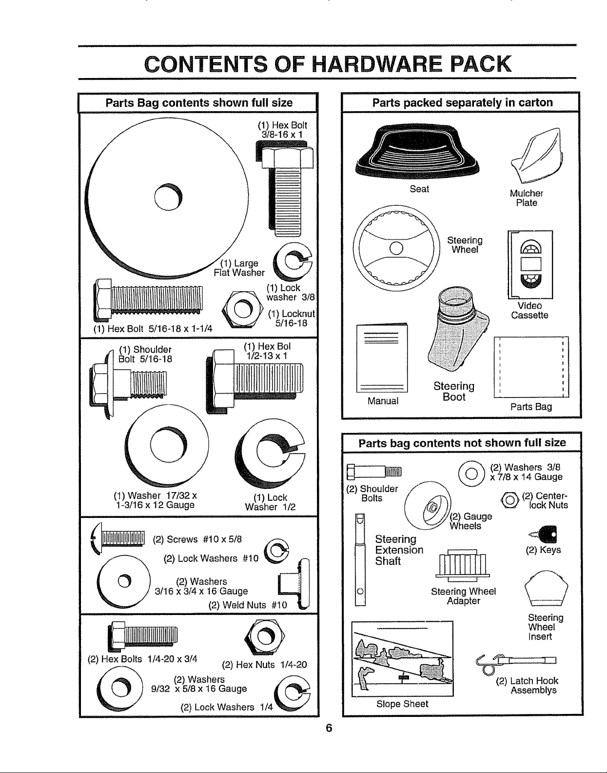
PACK
Parts Bag contents shown full size
(1) Hex Bolt
\
(1) Hex Bolt 5/16-18 x 1-t/4
(1) Shoulder (1) Hex Bol
Bolt 5/16-18 1/2-13 x I
3/8-16 x 1
(1) Lock
(1) Locknut
washer 3/8
5/16-18
Parts packed separately in carton
Manual
Seat
Steering
Wheel
Steering 1
Boot •
Mulcher
Plate
Video
Cassette
1
I
I
I
I
1'
Parts Bag
(1) Washer 17/32 x (1) Lock
1-3/16 x 12 Gauge Washer 1/2
I i,i, , iii i iiiiiiiiiiiiii,u 11111 i I
| (_ } (2) Washers I ! l
._ 3116X 3/4 X 16 Gauge _ l
H ,J"/'l'l'lJ'/' I I
(2) Weld Nuts #10 1LJ
@
(2) Hex Bolts 1/4-20 x 3/4
9/32 x 5/8 x 16 Gauge
(2) Washers
, m ,, i imnlnl HHHn,I i i l lll ill
(2) Lock Washers 1/4
(2) Hex Nuts 1/4-20
ii i i
Parts bag contents not shown full size
.......... m lllllllll ill nl i,,lliH,llllll
f/_-_ (2)Washers 3/8
_kJJ x7/8 x 14 Gauge
(2) ShoulderBoltsifz'q'_ _ !_B (2) Center-
(/"_/)) _ lock Nuts
\ [_////(2) Gauge
Steering
Extension
Shaft
o
Slope Sheet
uui
6
Wheels
,._,[__ (2) Keys
Steering Wheel
Adapter
(2) Latch Hook
Assemblys
Steering
Wheel
Insert
Page 7
LY
i IHH IIH,, I HI Illll i ......................... '" '"'"'
Your new tractor has been assembled at the factory with exception of those parts left unassembied for shipping purposes_.
To ensure safe and proper operation of your tractor all parts and hardware you assemble must be tightened securely_ Use
the correct tools as necessary to insure proper tightness°
TOOLS REQUIRED FOR ASSEMBLY
A socket wrench set wilt make assembly easier_ Standard
wrench sizes are listed_
(2) 7/16" wrenches Phillips Screwdriver
(1) 1/2" wrench Tire pressure gauge
(1) 9/16" wrench Utility knife
(1) 3/4" Socket w/drive rachet
When right or left hand is mentioned in this manual, it
means when you are in the operating position (seated
behind the steering wheel),.
TO REMOVE TRACTOR FROM CARTON
UNPACK CARTON
• Remove all accessible loose parts and parts cartons
from carton (See page 6).
- Cut, from top to bottom, along lines on all four corners
of carton, and lay panels fiat..
- Check for any additional loose parts or cartons and
remove.
BEFORE ROLLING TRACTOR OFF SKID
ADAPTER
5/t 6 LOCKNUT
'_'_ EXTENSION SHAFT
STEERING
BOOT
11, 5t16 HEX BOLT
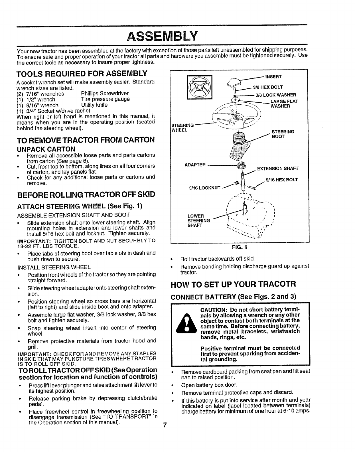
ATTACH STEERING WHEEL (See Fig. 1)
ASSEMBLE EXTENSION SHAFT AND BOOT
o Slide extension shaft onto lower steering shaft. Align
mounting holes in extension and lower shafts and
install 5/16 hex bolt and IocknuL Tighten securelyo
IMPORTANT: TIGHTEN BOLT AND NUT SECURELY TO
18-22 FT..LBS TORQUE,.
° Place tabs of steering boot over tab slots in dash and
push down to secure,
INSTALL STEERING WHEEL
• Position front wheels of the tractorsothey are pointing
straight forward,
. Slide steering wheel adapter onto steering shaft exten-
sion..
• Position steering wheel so cross bars are horizontal
(left to right) and slide insideboot and onto adapter.
° Assemble large flat washer, 3/8 lock washer, 3/8 hex
bolt and tighten securely.
° Snap steering wheel insert into center of steering
wheel
• Remove protective materials from tractor hood and
grill
IMPORTANT; CHECK FOR AND REMOVE ANY STAPLES
IN SKID THAT MAY PUNCTURE T1RESWHERETRACTOR
IS TO ROLL OFF SKID.
TO ROLL TRACTOR OFF SKID (See Operation
section for location and function of controls)
- Press tiftlever plunger and raise attachment lift leverto
its highest position°
• Release parking brake by depressing clutch/brake
pedal
• Place freewheel control in freewheeling position to
disengage transmission (See "TO TRANSPORT" in
the Operation section of this manual).
LOWER
STEERING
SHAFT
iI
FIG. 1
° Roll tractor backwards off skid_
° Remove banding holding discharge guard up against
tractor°
HOW TO SET UP YOUR TRACOTR
CONNECT BATTERY (See Figs. 2 and 3)
I I IIIII IIIIII I IIII I II I1'1 III IIIII
CAUTION: Do not short battery termi-
object to contact both terminals at the
nals by allowing a wrench or any other
sametime. Before connecting battery,
remove metal bracelets, wristwatch
bands, rings, etc.
Positive terminal must be connected
first to prevent sparking from acciden-
tal grounding.
................................... , ,,,,,,
Remove cardboard packing from seat pan and lift seat
pan to raised position,.
o
Open batter':/box door.
o
Remove terminal protective caps and discard.
o
tf this battery is put intoser¢ice after month and year
indicated on label (label located between terminals)
charge battery for minimum of one hour at 6-10 amps,
7
Page 8
iiu iiiJll iii iiii Ill i
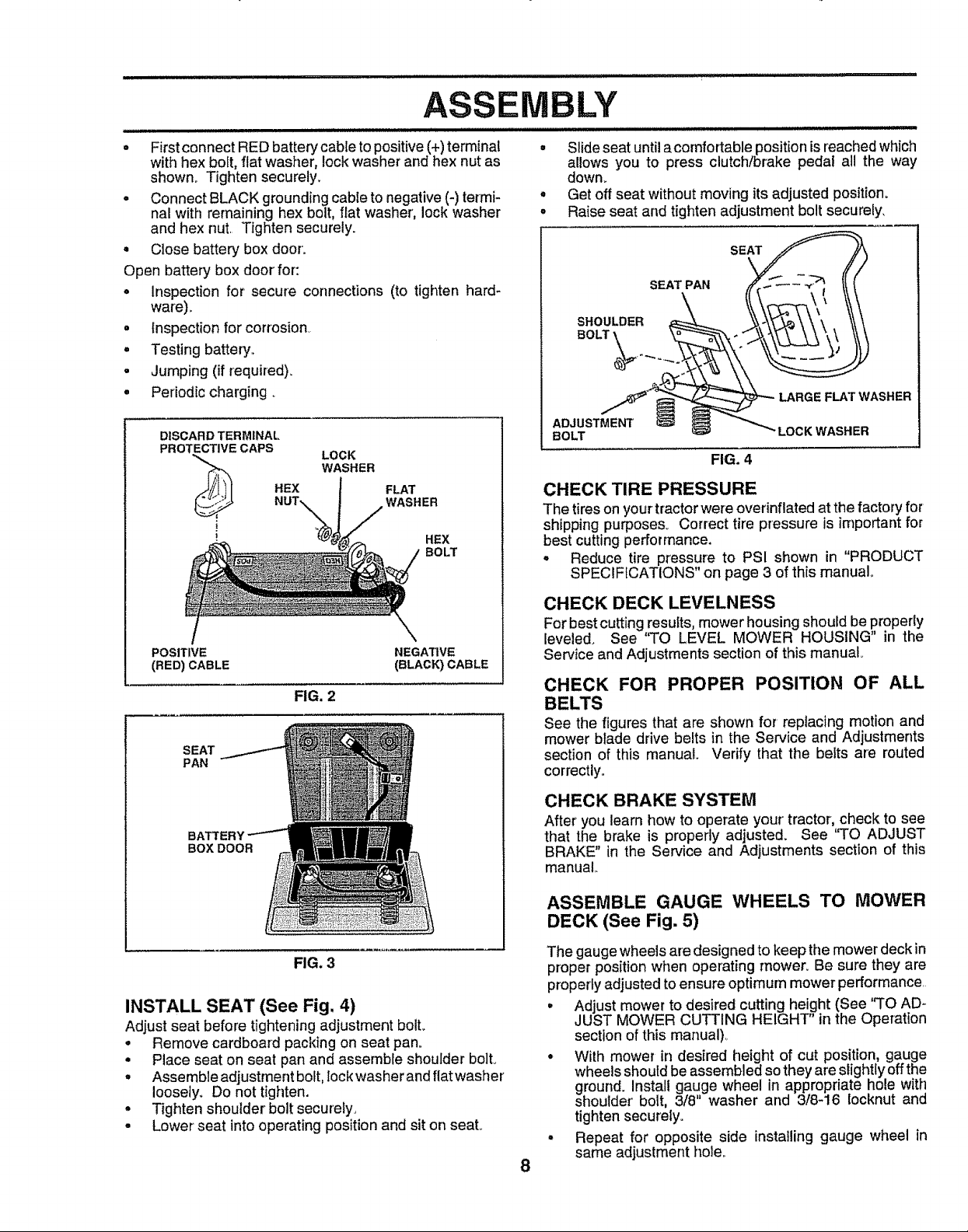
. Firstconnect RED battery cable to positive (+) terminal
with hex bolt, flat washer, lock washer and hex nut as
shown. Tighten securely,
• Connect BLACK grounding cable tonegative (-)termi-
nal with remaining hex bolt, flat washer', lock washer
and hex nut, Tighten securely.
° Close batter:/box door:
Open battery box door' for:
• Inspection for secure connections (to tighten hard-
ware),,
• Inspection for corrosion,
° Testing battery,,
• Jumping (if required).
° Periodic charging.
DISCARD TERMINAL
PROTECTIVE CAPS
_, REX
LOCK
WASHER
FLAT
WASHER
HEX
BOLT
IBLY
• Slide seat until acomfortable position is reached which
allows you to press clutch/brake pedal all the way
down_
Get off seat without moving its a_usted position°
Raise seat and tighten adjustment bolt securely,
SEAT
SEAT PAN
FLAT WASHER
ADJUSTMENT
BOLT LOCK WASHER
FIG. 4
CHECK TIRE PRESSURE
The tireson yourtractor were overinflatedat the factory for
shippingpurposes_ Correct tire pressure is important for
best cuttingperformance.
• Reduce tire pressure to PSI shown in "PRODUCT
SPECIFICATIONS" on page 3 of this manual..
POSITIVE NEGATIVE
(RED) CABLE (BLACK) CABLE
FIG. 2
SEAT
PAN
BOX DOOR
FIG. 3
INSTALL SEAT (See Fig. 4)
Adjust seat before tightening adjustment boll
° Remove cardboard packing on seat pan.
° Place seat on seat pan and assemble shoulder bolto
. Assembfeadjustmentboft, lockwasherandflatwasher
loosely. Do not tighten.
° Tighten shoulder bolt securely,
° Lower seat into operating position and sit on seat,,
CHECK DECK LEVELNESS
For best cuttingresults,mower housingshould be properly
leveled° See '_TO LEVEL MOWER HOUSING" in the
Service and Adjustments section ofthis manual
CHECK FOR PROPER POSITION OF ALL
BELTS
See the figures that are shown for replacing motion and
mower blade drive belts in the Service and Adjustments
section of this manual. Verify that the belts are routed
correctly.
CHECK BRAKE SYSTEM
After you learn how to operate your tractor, check to see
that the brake is properly adjusted. See "TO ADJUST
BRAKE" in the Service and Adjustments section of this
manual,,
ASSEMBLE GAUGE WHEELS TO MOWER
DECK (See Fig. 5)
The gauge wheels are designed to keep the mower deck in
proper position when operating mower, Be sure they are
properly adjusted to ensure optimum mower performance,
• Adjust mower to desired cutting height (See "TO AD-
JUST MOWER CUTTING HEIGHT" in the Operation
section of this manual),
• With mower in desired height of cut position, gauge
wheels should be assembled so they are slightly offthe
ground. Install gauge wheel in appropriate hole with
shoulder bolt, 3/8 washer and 3/8-16 Iocknut and
tighten securely.
° Repeat for opposite side installing gauge wheel in
same adjustment hole.
8
Page 9
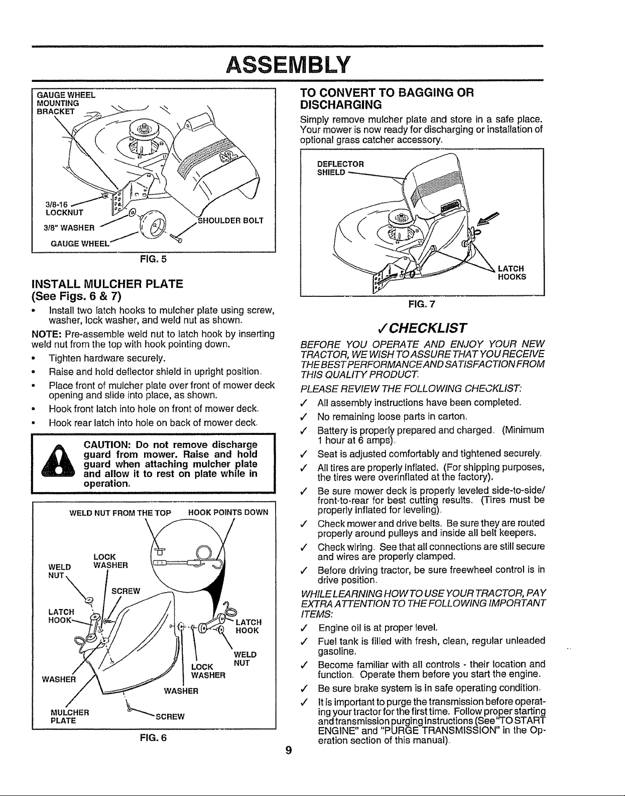
GAUGE WHEEL
MOUNTING
BRACKET
\,
EMBLY
i i lllll i i llllllllll,llllllll,lllll llliHl,,,,J,lll ill illl II/,/,/H,,,J,,,,
TO CONVERT TO BAGGING OR
DISCHARGING
Simply remove mulcher plate and store in a safe place.
Your mower is now ready for discharging orinstallationof
optional grass catcher accessory'.
DEFLECTOR
SHIELD
_OULDER BOLT
FIG. 5
INSTALL MULCHER PLATE
(See Figs. 6 & 7)
• Install two latch hooks to mulcher plate using screw,
washer, lock washer, and weld nut as shown_
NOTE: Pre-assemble weld nut to latch hook by inserting
weld nut from the top with hook pointing down.
• Tighten hardware securely.
. Raise and hold deflector shield in upright position.
° Place front of mulcher plate over front of mower deck
opening and slide into place, as shown.
° Hook front latch into hole on front of mower deck.
° Hook rear latch into hole on back of mower deck.
i,l_l,ll,ll,i..................................... ,i
guard from mower. Raise and hold
1_ CAUTION: Do not remove discharge
WELD WASHER
NUT "\'_,t._ _
LATCH
WASHER
MULCHER
PLATE
guard when attaching mulcher plate
and allow it to rest on plate while in
operation°
WELD NUT FROM THE TOP HOOK POINTS DOWN
LOCK
HOOK
WELD
LOCK
WASHER
NUT
FIG. 6
LATCH
HOOKS
FIG, 7
,/'CHECKLIST
BEFORE YOU OPERATE AND ENJOY YOUR NEW
TRACTOR, WE WISH TOASSURE THAT YOU RECEIt/E
THE BEST PERFORMANCE AND SATISFACTION FROM
THIS QUALITY PRODUCT.
PLEASE REVIEW THE FOLLOWING CHECKLIST:
,/ All assembly instructions have been completed.
,/ No remaining loose parts in carton
# Battery is properly prepared and charged (Minimum
1 hour at 6 amps).
,/ Seat is adjusted comfortably and tightened securely,
v" All tires are properly inflated. (For shipping purposes,
the tires were ovednflated at the factory),
v" Be sure mower deck is properly leveled side-to-side/
front-to-rear for best cutting results. (Tires must be
properlyinflated for leveling)
,/ Check mower and drive belts, Be surethey are routed
properly around pulleys and inside all belt keepers.
#" Check wiring. See that all connections are still secure
and wires are properly clamped.
v" Before driving tractor, be sure freewheel control is in
drive position.
WHILE LEARNING HOWTO USE YOUR TRACTOR, PAY
EXTRA ATTENTION TO THE FOLLOWING IMPORTANT
ITEMS:
#" Engine oil is at proper level.
v" Fuel tank isfilled with fresh, clean, regular unleaded
gasoline°
J" Become familiar with all controls - their location and
function, Operate them before you start the engine.
,/ Be sure brake system is in safe operating condition.
,/ ttis important to purge the transmission before operat-
ing your tractor for the first time. Follow proper starting
and transmission purging Instructions(See'TO START
ENGINE" and "PURGE TRANSMISSION" in the Op-
eration section of this manual)
9
Page 10
OPERATION
i,,,,,,,....... i,.ll.,uuu , iul,,.,_ , ............ l llll Hn..lll ll,l,llll,lu
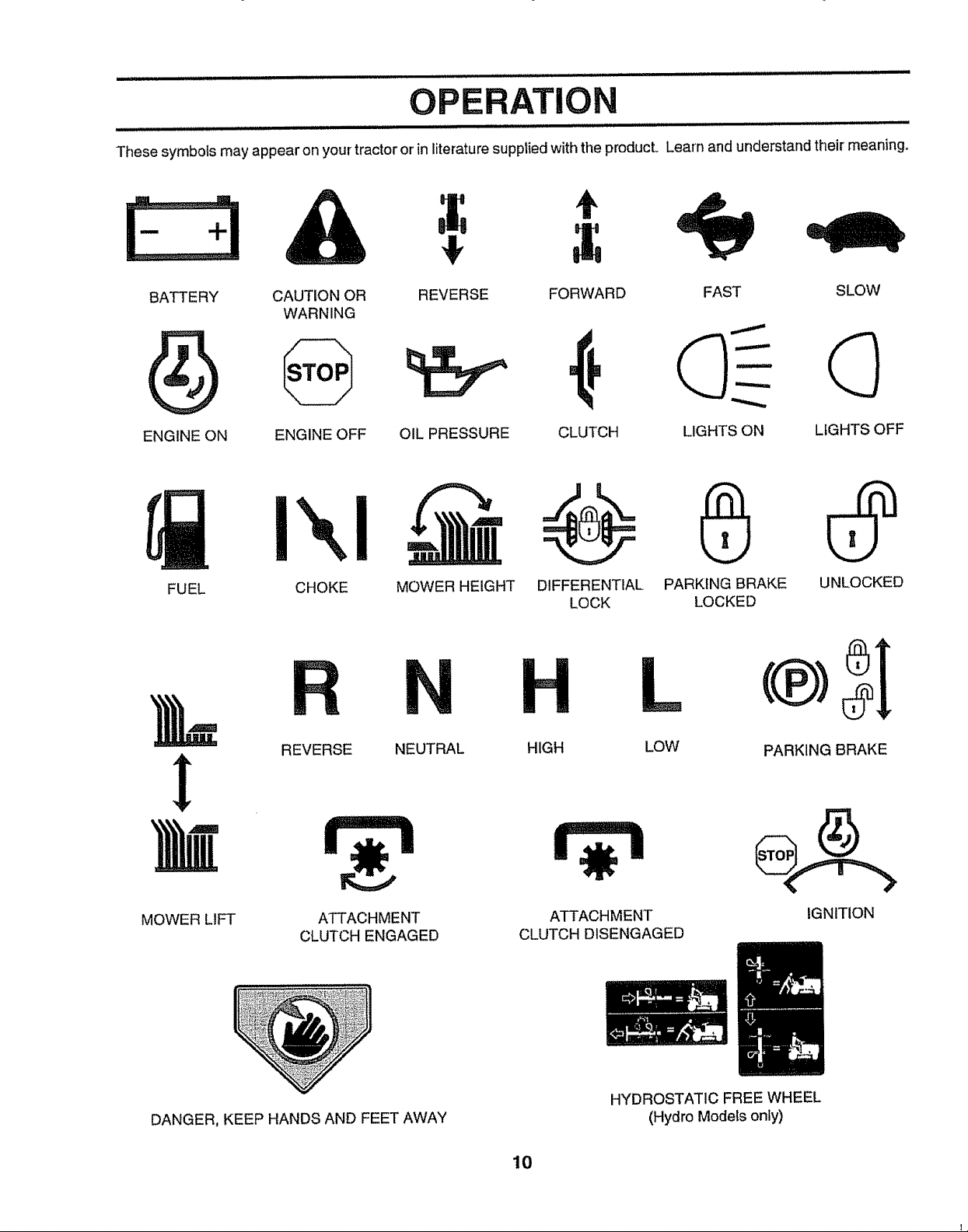
These symbols may appear on yourtractor orin literature supplied with the producL Learn and understand their meaning°
A
BATTERY CAUTION OR
WARNING
ENGINE ON ENGINE OFF
Ikl-
FUEL
CHOKE MOWER HEIGHT DIFFERENTIAL PARKING BRAKE UNLOCKED
REVERSE FORWARD FAST SLOW
OIL PRESSURE CLUTCH LIGHTS ON LIGHTS OFF
LOCK LOCKED
REVERSE NEUTRAL
MOWER LIFT
DANGER, KEEP HANDS AND FEET AWAY
ATTACHMENT
CLUTCH ENGAGED
HIGH LOW
ATTACHMENT
CLUTCH DISENGAGED
HYDROSTATIC FREE WHEEL
(Hydro Models only)
10
PARKING BRAKE
IGNITION
Page 11
OPERAT!
i i ii i iill
KNOW YOUR TRACTOR
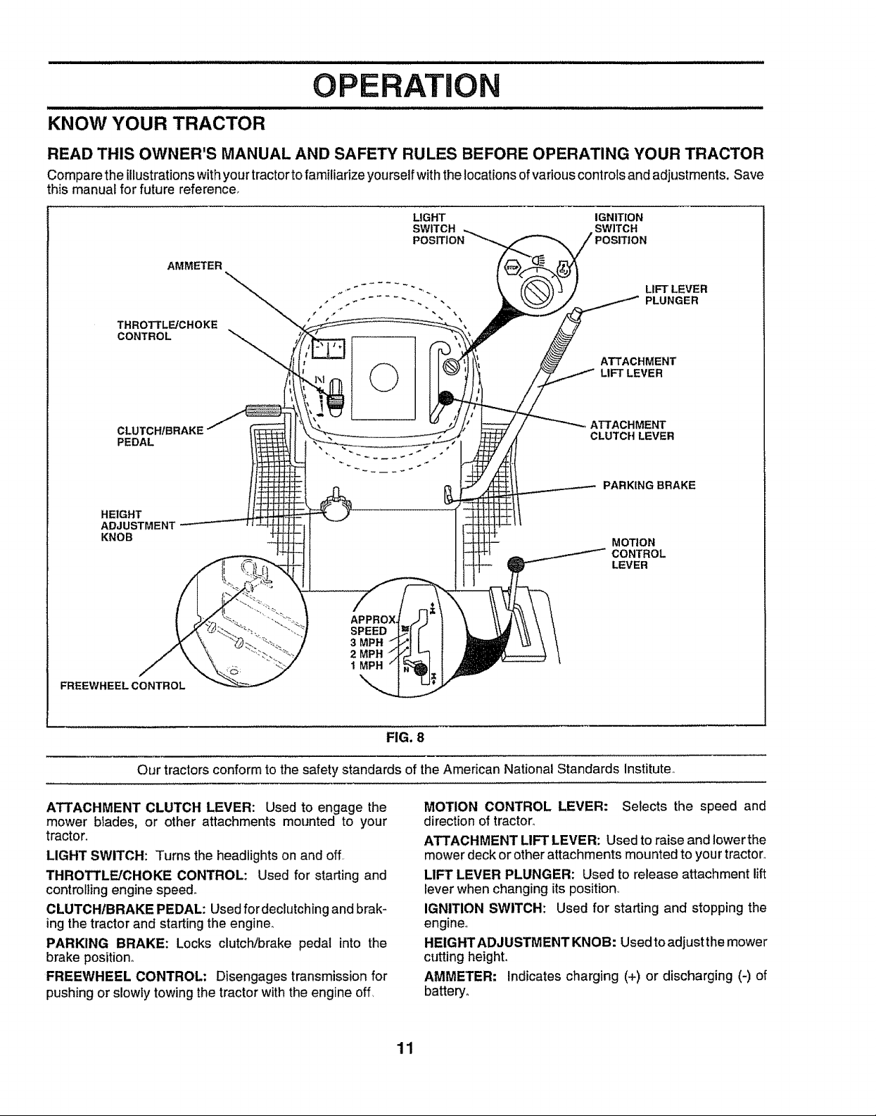
READ THIS OWNER'S MANUAL AND SAFETY RULES BEFORE OPERATING YOUR TRACTOR
Compare the illustrationswithyour tractor to familiarize yourself withthelocations of various controls and adjustments. Save
this manual for future reference,
LIGHT IGNITION
SWITCH SWITCH
AMMETER
THROTTLE/CHOKE
CONTROL
©
PEDAL
POSITION
LIFT LEVER
PLUNGER
ATTACHMENT
LIFT LEVER
ATTACHMENT
CLUTCH LEVER
PARKING BRAKE
HEIGHT
ADJUSTMENT
KNOB
SPEED
3 MPN
2 MPH
1MPH
FREEWHEEL CONTROL
Our tractorsconform to the safety standards of the American National Standards Institute,,
ATTACHMENT CLUTCH LEVER: Used to engage the
mower bIades, or other attachments mounted to your
tractor.
LIGHT SWITCH: Turns the headlights on and off
THROTTLE/CHOKE CONTROL: Used for starting and
controlling engine speed.
CLUTCHIBRAKE PEDAL: Used fordeclutching and brak-
ing the tractor and starting the engine_
PARKING BRAKE: Locks clutch/brake pedal into the
brake position_
FREEWHEEL CONTROL; Disengages transmission for
pushing or slowly towing the tractor with the engine off,
MOTION
CONTROL
LEVER
FIG. 8
MOTION CONTROL LEVER: Selects the speed and
direction of tractor°
ATTACHMENT LIFT LEVER: Used to raise and lowerthe
mower deck or other attachments mounted to your tractor_
LIFT LEVER PLUNGER: Used to release attachment lift
lever when changing its position,
IGNITION SWITCH: Used for starting and stopping the
engine,,
HEIGHTADJUSTMENTKNOB: Usedtoadjustthe mower
cutting height,,
AMMETER; Indicates charging (+) or discharging (-) of
battery°
11
Page 12
The operation of any tractor can result in foreign objects thrown into the eyes, which can
result insevere eye damage. Always wear safety glasses or eye shields while operating your
tractor or performing any adjustments or repairs. We recommend a wide vision safety mask
over the spectacles or standard safety glasses.
=lii illlllHll Lll I I H=H II IHHlllll
HOW TO USE YOUR TRACTOR
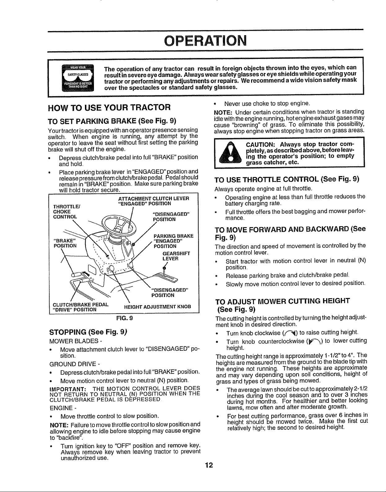
TO SET PARKING BRAKE (See Fig. 9)
Yourtractorisequippedwithan operatorpresence sensing
switch When engine is running, any attempt by the
operator to leave the seat without first setting the parking
brake will shut off the engine
= Depress clutch/brake pedal intofull 'BRAKE" position
and hold
• Place parking brake tever inENGAGED' position and
release pressu refrom clutch/brake pedal Pedalshould
remain in "BRAKE position Make sure parking brake
will hold tractor secure
ATTACHMENT CLUTCH LEVER
THROT]'LE/
CHOKE "DISENGAGED"
CONTROL POSITION
"BRAKE .... ENGAGED"
POSITION POSITION
CLUTCH/BRAKE PEDAL
"DRIVE" POSITION
STOPPING (See Fig. 9)
MOWER BLADES -
° Move attachment clutch lever to"DISENGAGED" po
sition
GROUND DRIVE
• Depress clutch/brake pedal intofull "BRAKE' position
- Move motion control lever to neutral (N) position
IMPORTANT: THE MOTION CONTROL LEVER DOES
NOT RETURN TO NEUTRAL (N) POSITION WHEN THE
CLUTCHIBRAKE PEDAL iS DEPRESSED
ENGINE
• Move throttle control to slow position
NOTE: Failure to move throttle control to slow positionand
allowing engine to idle before stopping may cause engine
to 'backfire'
• Turn ignition key to OFF" position and remove key
Always remove key when leaving tractor to prevent
unauthorized use
"ENGAGED" POSITION
PARKING BRAKE
GEARSHIFT
LEVER
"DISENGAGED"
POSITION
HEIGHT ADJUSTMENT KNOB
FIG. 9
, Never use choke to stop engine
NOTE: Under certain conditions when tractor is standing
idlewith the engine running, hot engine exhaust gases may
cause 'browning' of grass To eliminate this possibility,
always stop engine when stopping tractor on grass areas
CAUTION: Always stop tractor corn- |
pletely, asdescribed above, before leav-
ing the operator's position; to empty
grass catcher, etc._..............
TO USE THROTTLE CONTROL (See Fig. 9)
Always operate engine at full throttle
= Operating engine at less than full throttle reduces the
battery charging rate
,, Full throttle offers the best bagging and mower perfor
mance
TO MOVE FORWARD AND BACKWARD (See
Fig. 9)
The direction and speed of movement is controlledby the
motion controllever,.
° Start tractor with motion control lever in neutral (N)
position
° Release parking brake and clutch/brake pedal
° SIowly move motion control lever to desired position
TO ADJUST MOWER CUTTING HEIGHT
(See Fig. 9)
The cutting height iscontrolled by turning the height adjust_
ment knob in desired direction
= Turn knob clockwise (f-N) to raise cutting height
° Turn knob counterclockwise (_-_)to lower cutting
height
The cutting height range is approximately t 1/2" to 4'L The
heights aremeasured from the ground to the blade tip with
the engine not running These heights are approxtmate
and may vary depending upon soil conditions, height of
grass and types of grass being mowed
• The average lawn should be cut to approxirnateEy2-1/2
inchesduring the cool season and to over 3 inches
during hot months For heatthier and better looking
lawns mow often and after moderate growth
• For best cutting performance, grass over6 inchesin
height should be mowed twice Make the first cut
relatively high; the second to desired height
12
|
I
Page 13
i
OPERATION
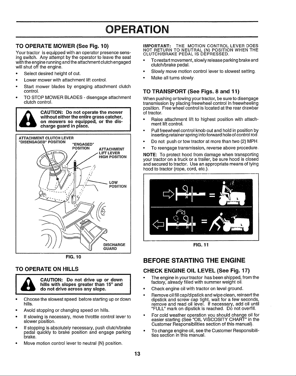
TO OPERATE MOWER (See Fig, 10)
Your tractor isequipped with an operator presence sens-
ingswitch. Any attempt by the operator to leave the seat
with the engine running andthe attachment clutch engaged
will shut off the engine
o Select desired height of cut.
- Lower mower with attachment lift control.
• Start mower blades by engaging attachment clutch
control
• TO STOP MOWER BLADES- disengage attachment
clutch control.
CAUTION: Do not operate the mower
without either the entire grass catcher,
on mowers so equipped, or the dis-
charge guard in place.
ATTACHMENT CLUTCH LEVER
"DISENGAGED" POSITION
\
"ENGAGED"
POSITION
ATTACHMENT
LEVER
HIGH POSITION
IMPORTANT: THE MOTION CONTROL LEVER DOES
NOT RETURN TO NEUTRAL (N) POSITION WHEN THE
CLUTCH/BRAKE PEDAL IS DEPRESSED
" To restart movement, slowly release parking brake and
clutch/brake pedal
• Slowly move motion control lever to slowest setting.
• Make all turns slowty
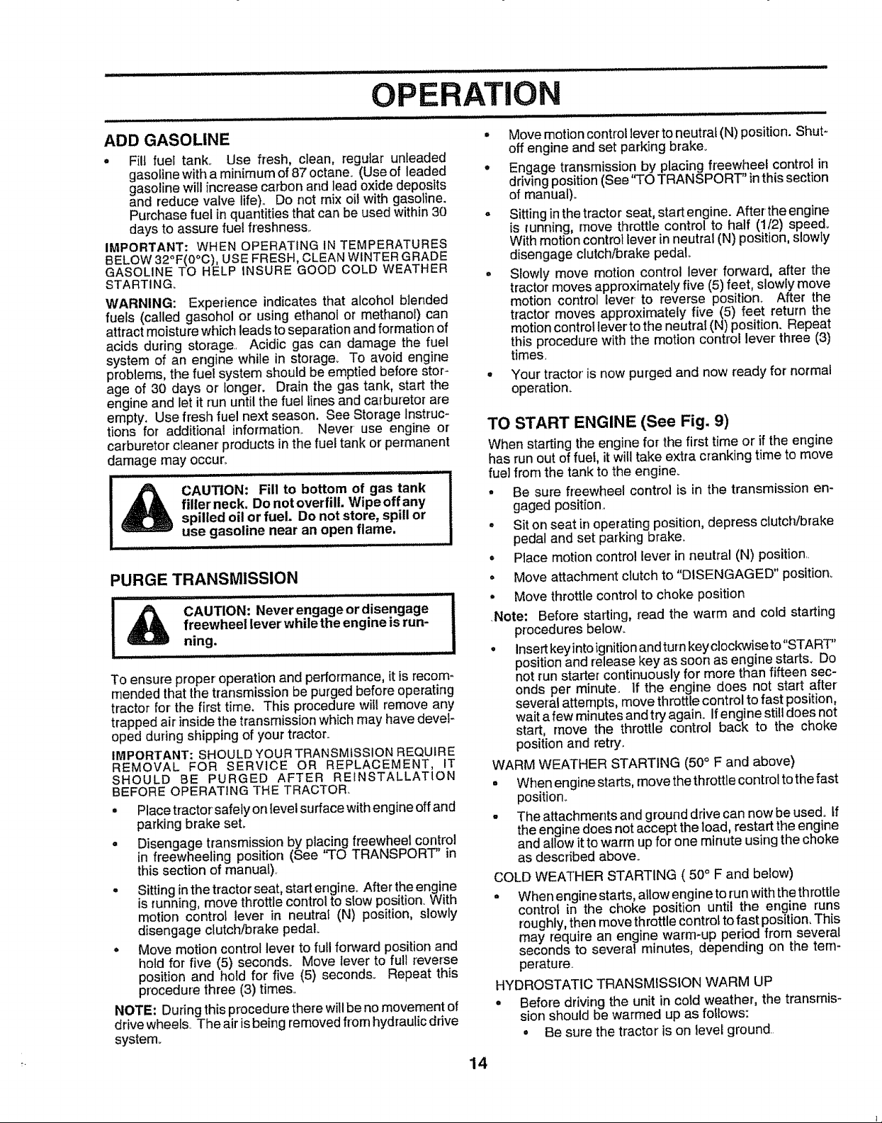
TO TRANSPORT (See Figs. 8 and 11)
When pushing or towing your tractor, be sure to disengage
transmission by placing freewheel control infreewheeling
position, Free wheel control is located at the rear drawbar
of tractor_
• Raise attachment lift to highest position with attach-
ment lift control.
. Put!freewheel control knob outand hold inposition by
inserting retainer spring intoforward hoJeof controt rod
• Do not push or tow tractor at more than two (2) MPH
° To reengage transmission, reverse above procedure°
NOTE: To protect hood from damage when transporting
your tractor on a truck or a traiier, be sure hood is closed
and secured to tractor. Use an appropriate means of tying
hood to tractor (rope, cord, etc)
DISCHARGE
GUARD
FIG. 10
TO OPERATE ON HILLS
&
o
Choose the slowest speed before starting up or down
hills°
°
Avoid stopping or changing speed on hills_
If slowing is necessary, move throttle control lever to
slower position°
°
If stopping is absolutely necessary, pushclutch/brake
pedal quickly to brake position and engage parking
brake°
Move motion control lever to neutral (N) position_
FIG. 11
BEFORE STARTING THE ENGINE
CHECK ENGINE OIL LEVEL (See Fig. '17)
• The engine in your tractor has been shipped, from the
factory, already filled with summer weight oil.
• Check engine oil with tractor on level ground_
• Remove oil fill cap/dipstick and wipe clean, reinsert the
dipstick and screw cap tight, wait for a few seconds,
remove and read oil level. If necessary, add oil until
"FULL" mark on dipstick is reached_ Do not overfill°
• For cold weather operation you should change oil for
easier starting (See "OIL VISCOSITY CHART" in the
Customer Responsibilities section of this manual)
• To change engine oil see the Customer Responsibili-
ties section in this manual
13
Page 14
H ill IHll Illllllllll I IJI/IIUH,,I,, Illl II ,ll,ll, Ill II' II Illl. I'l
ATION
ii ii, ill , Hll i i,i iHll,ll _ ,,_,,_..................................................................... .............
ADD GASOLINE • Movemottoncontrollevertoneutral(N)position. Shut_
, Fill fuel tank,. Use fresh, clean, regular unleaded
gasoline with a minimum of 87octane. (Use of leaded
gasoline will increase carbon and lead oxide deposits
and reduce valve life).. Do not mix oil with gasoline.
Purchase fuel in quantities that can be used within 30
days to assure fue! freshness..
IMPORTANT: WHEN OPERATING INTEMPERATURES
BELOW 32°F(0°C), USE FRESH, CLEAN WINTER GRADE
GASOLINE TO HELP INSURE GOOD COLD WEATHER
STARTING_
WARNING: Experience indicates that alcohol blended
fuels (called gasohol or using ethanol or methanol) can
attract moisture which leads to separation andformation of
acids during storage.. Acidic gas can damage the fuel
system of an engine while in storage° To avoid engine
problems, the fuel system should be emptied before stor-
age of 30 days or longer. Drain the gas tank, start the
engine and let it run until the fuel lines and carburetor are
empty. Use fresh fuel next season. See Storage Instruc-
tions for additional information._ Never use engine or
carburetor cleaner products in the fuel tank or permanent
damage may occur,,
,,,,,,,,,,,,...... ............
fillerneck, Do not overfill, Wipeoffany
!_ CAUTION: Fill to bottom of gas tank
spilled oil or fuel, Do not store, spill or
use gasoline near an open flame,
PURGE TRANSMISSION
freewheel lever while the engine isrun-
........................ iI & CAUTION: Never engage or disengage
ning. ............................
To ensure proper operation and performance, it is recom*
mended that the transmission be purged before operating
tractor for the first time. This procedure wiil remove any
trapped air inside thetransmission which may have deveF
oped during shipping of your tractor..
IMPORTANT: SHOULD YOUR TRANSMISSION REQUIRE
REMOVAL FOR SERVICE OR REPLACEMENT, IT
SHOULD BE PURGED AFTER REfNSTALLATION
BEFORE OPERATING THE TRACTOR.
° Placetractor' safely on level surface withengine offand
parkingbrake seL
o Disengage transmission by placing freewheel control
in freewheeling position (See q'O TRANSPORT' in
this section of manual)..
• Sitting inthe tractor seat, start engine..After the engine
is running, move throttle control to slow position_ With
motion control lever in neutral (N) position, slowly
disengage clutch/brake pedal
° Move motion control lever to full forward position and
held for five (5) seconds° Move lever to ful_reverse
position and hold for five (5) seconds.. Repeat this
procedure three (3) times_
NOTE: Dudng this procedure there will be no movement of
drive wheels.. The air isbeing removed from hydraulic drive
system.
off engine and set parking brake.
• Engage transmission by placing freewheel control in
driving position (See'q'O TRANSPORT' inthis section
of manual)_
° Sitting in the tractor seat, start engine. After-the engine
is running, move throttle control to half (1/2) speed.
With motion control lever in neutral (N) position, slowly
disengage clutch/brake pedal.
- Slowly move motion control lever' forward, after the
tractor moves approximately five (5) feet, slowly move
motion control lever to reverse position. After the
tractor moves approximately five (5) feet return the
motion control leverto the neutral (N) position. Repeat
this procedure with the motion contro! lever three (3)
times.
° Your tractor' is now purged and now ready for' normal
operation.
TO START ENGINE (See Fig, 9)
When starting the engine for the first time or if the engine
has run out of fuel, itwilltake extra cranking time to move
fuel fromthe tank tothe engine_
• Be sure freewheel control is in the transmission en-
gaged position.
° Sit on seat in operating position, depress clutch/brake
pedal and set parking brake.
° Place motion control lever in neutral (N) position..
• Move attachment clutch to "DISENGAGED" position_
° Move throttle control to choke position
,Note: Before starting, read the warm and cold starting
procedures below_
• Insert keyinto ignition andturn key clockwise to"START"
position and release key as soon as engine starts. Do
not run starter continuously for more than fifteen sec-
onds per minute. If the engine does not start after
several attempts, move throttle control to fast position,
wait afew minutes and try'again. Ifengine stilt does not
start, move the throttle control back to the choke
position and retry.
WARM WEATHER STARTING (50° F and above)
• When engine starts, move the throttle control tothe fast
position..
• The attachments and ground drive can now be used. tf
the engine does not accept the load, restart the engine
and allow itto warm up for one minute using the choke
as described above.
COLD WEATHER STARTING ( 50° F and below)
° When engine starts, atlowengine to run with thethrottle
control in the choke position until the engine runs
roughly, then move throttle control to fast position, This
may require an engine warm-up period from several
seconds to sever'at minutes, depending on the tern-
perature.
HYDROSTATIC TRANSMISSION WARM UP
• Before driving the unit in cold weather, the transmis-
sion should be warmed up as follows:
• Be sure the tractor is on level ground.
14
Page 15
OPERAT!
..................................... ,,,H' M '"',11",'1""'1'1' Jl I'1'1' ..........................
o Be sure the tractor is on level ground+
° Place the motion control lever in neutral
Release the parking brake and let the clutch/brake
slowly return to operating position.
o Allow one minute for transmission to warm up.
This can be done during the engine warm up
period_
- The attachments can also be used during the engine
warm-up periodafterthe transmission hasbeen warmed
up.
NOTE; If at a high altitude (above 3000 feet) or in cold
tempe ratures (below 32 F)the carburetor fuel mixture may
need to be adjusted for best engine performance. See 'q'O
ADJUST CARBURETOR" in the Service and Adjustments
section of this manual
MOWING TIPS
• Tire chains cannot be used when the mower housing
is attached to tractor+
° Mower should be properly leveled for best mowing
performance. See "TO LEVEL MOWER HOUSING" in
the Service and Adjustments section of this manual
• The left hand side of mower should be used for trim-
ming.
• Drive so that clippings are discharged onto the area
that has been cut. Have the cut area to the right of the
tractor. This will result in a more even distribution of
clippings and more uniform cutting+
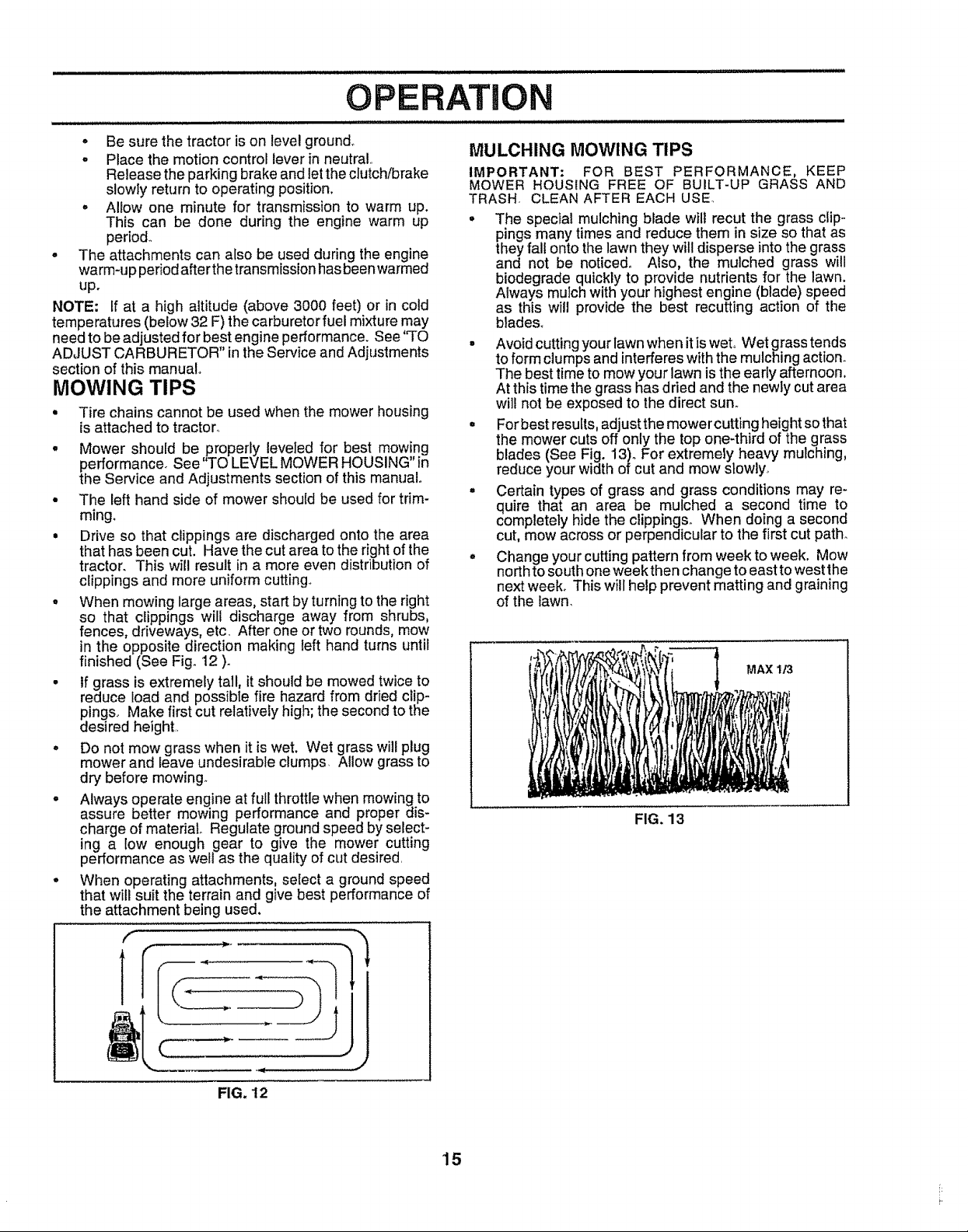
° When mowing large areas, start by turning to the right
so that clippings will discharge away from shrubs,
fences, driveways, etc, After one or two rounds, mow
in the opposite direction making left hand turns until
finished (See Fig+12 )+
• If grass is extremely tall, it should be mowed twice to
reduce load and possible fire hazard from dried clip-
pings. Make first cut relatively high; the second to the
desired height,
° Do not mow grass when it is wet. Wet grass will plug
mower and leave undesirable clumps Allow grass to
dry before mowing.
- Always operate engine at full throttle when mowing to
assure better mowing performance and proper dis-
charge of material. Regulate ground speed byselect-
ing a low enough gear to give the mower cutting
performance as welt as the quality of cut desired
• When operating attachments, select a ground speed
that will suit the terrain and give best performance of
the attachment being used.
f
MULCHING MOWING TIPS
IMPORTANT: FOR BEST PERFORMANCE, KEEP
MOWER HOUSING FREE OF BUILT-UP GRASS AND
TRASH CLEAN AFTER EACH USE
• The special mulching blade will recur the grass clip-
pings many times and reduce them in size so that as
they fall onto the lawn they will disperse into the grass
and not be noticed° Also, the mulched grass will
biodegrade quickly to provide nutrients for the lawn.
Always mulchwith your highest engine (blade) speed
as this will provide the best recutting action of the
blades°
• Avoidcuttingyourlawnwhen itiswet Wet grasstends
toformclumpsand interfereswiththemulchingaction.
The best time to mow your lawn is the early afternoon.
At this time the grass has dried and the newly cut area
will not be exposed to the direct sun.
° Forbest resuits, adjust the mower cutting height so that
the mower cuts off only the top one-third of the grass
blades (See Fig. 13)+For extremely heavy muiching,
reduce your width of cut and mow slowly+
. Certain types of grass and grass conditions may re-
quire that an area be mulched a second time to
completely hide the clippings. When doing a second
cut, mow across or perpendicular to the first cut path.
o Change your cutting pattern from week to week. Mow
north to south one week then change to east to west the
next week. This will help prevent matting and graining
of the lawn.
MAX 1/3
FIG. 13
t
FIG. 12
15
Page 16
CUSTOMER RESPON BILl
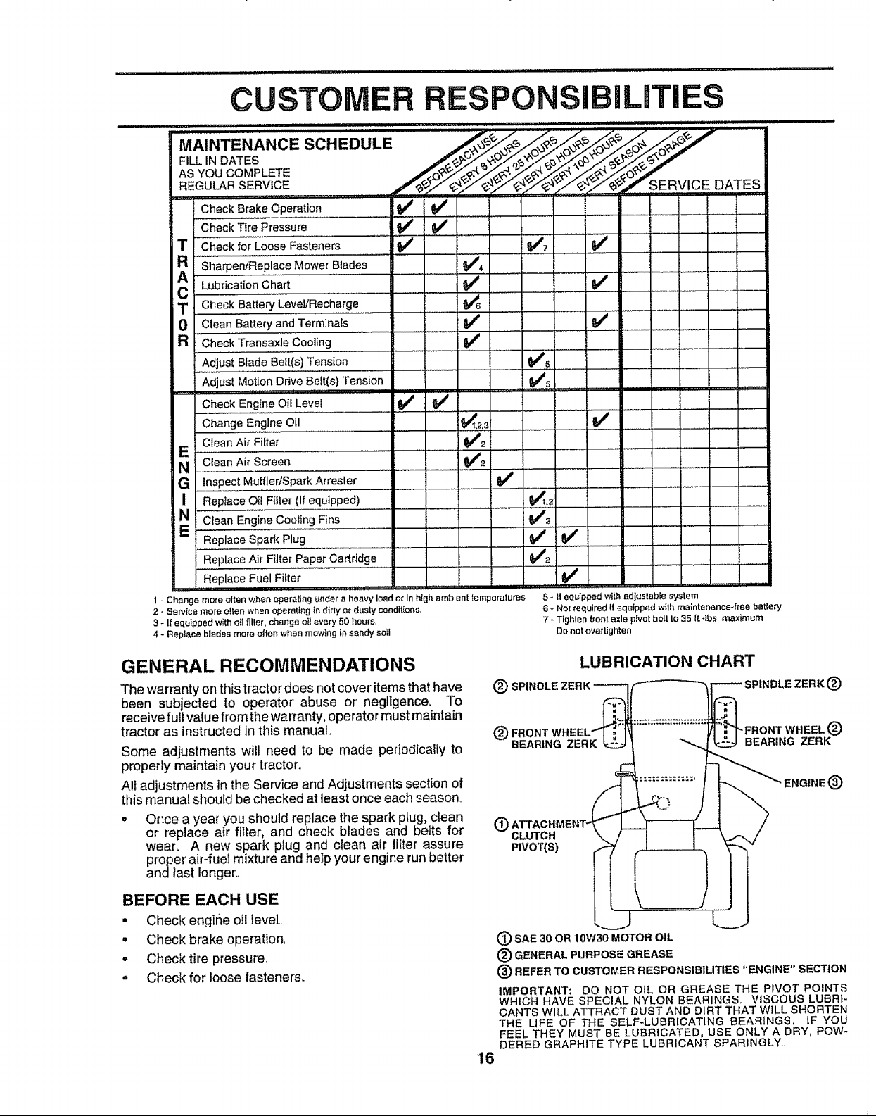
MAINTENANCE SCHEDULE /_/_o_-_./_o_J
AS YOU COMPLETE _3_ _" _'_'_' _"_'-' _-' _,_ ._O_'_
REGULAR SERVICE ......... _/_-_.,,__ RVICE DATE S
Check Brake Operation if _#' ....................
Check Tire Pressure .............if ___
T Check for Loose FaSteners _ _7 _/ .....
a Sharpen/Replace Mower Blades
Lubricatioo ha. ....V' .......
C ........... .................
i T Check Battery Level/Recharge" , _ ......
0 Clean 'Battery'a'nd Terminals .............. _/ ....... M #
R Check' Transaxi'e"cooling _ _
Adjus'i"Blade"'Be'it(s)Tension _#'s
Adjust Motion Drive Belt(s) Tension i_#'s
Check Engine Oil Levei if =_
Change Engine oil ............................ t_t,2,3 if .............
Clean Air Filter' _#_2
E' Clean Air Screen ........ _#'2 .................... ............
.......... ' ,rl,i,
G Inspect MufflerlSpark Attester t## ......................
I Replace OilFilter(Ifeq'u'i'Pped) VTL2 ......... _=
..... = ...... ..............
.................... ,.... ..., ...........
N Clean Engine Cooling Eins t##'2 _=
Replace Spark Plug ........ ' .......... ,',,,i' _# _ ",',','ii........
Replace Air Filter Paper Cartridge _2 ,,
Replace' Fuel Filter ' , ................... _ ........
1 - Change more often when eperaling _nder a heavy load of in high ambient temperatures
2- Service more oIlen when operating in dirty or dusty condit{ons,
3 * If equipped wittl otIfiller_ change eIl every 50 hours
4 - Repiace blades more often when mowing Insandy soil
GENERAL RECOMMENDATIONS
The warrantyon thistractordoes not cover itemsthat have
been subjected to operator' abuse or negligence. To
receive full valuefrom the warranty,operator must maintain
tractor as instructed in this manual,.
Some adjustments will need to be made periodically to
properly maintain your tractor°
All adjustments in the Service and Adjustments section of
this manual should be checked at least once each season.,
• Once a year you should replace the spark plug, clean
or replace air filter, and check blades and belts for
wear, A new spark plug and clean air filter assure
proper air-fuel mixture and help your engine runbetter
and last longer,
BEFORE EACH USE
• Check engihe oil level
• Checkbrake operation,
° Checktire pressure,
° Check for loose fasteners_
5 _ I! equipped with adjustable system
iS- Not required {f equipped withmaintenance-free batle_
7 - Tighlen front axle pivot belt to35 It, *lba maximum
Do not overtighten
LUBRICATION CHART
(_ SPINDLE ZERK_
(_) FRONT WHEELfl ; r,
BEARING ZERK
CLUTCH '
PIVOT(S)
SAE 30 OR 10W30 MOTOR OIL
(_ GENERAL PURPOSE GREASE
(_) REFER TO CUSTOMER RESPONSIBILITIES "ENGINE" SECT1ON
IMPORTANT: DO NOT OIL OR GREASE THE PIVOT POINTS
WHICH HAVE SPECIAL NYLON BEARINGS,, VISCOUS LUBRI-
CANTS WILL ATTRACT DUST AND DIRT THAT WILL SHORTEN
THE LIFE OF THE SELF-LUBR[CATING BEARINGS, IF YOU
FEEL THEY MUST BE LUBRICATED, USE ONLY A DRY, POW_
DERED GRAPHITE TYPE LUBRICANT SPARINGLY
16
-FRONT WHEEL _)
BEARING ZERK
ENGINE (_)
®
Page 17
CUSTOMER RESPONSIBiLiTiES
TRACTOR
Always observe safety rules when performing any mainte-
nance.
BRAKE OPERATION
If tractor requires more than six (6) feet stopping distance
at high speed in highest gear, then brake must be adjusted.,
(See 'q'O ADJUST BRAKE" in the Service and Adjust-
ments section of this manual)_
TIRES
• Maintain proper air pressure in all tires (See "PROD-
UCT SPECIFICATIONS" on page 3 of this manual).,
. Keep tires free of gasoline, oil, or insect control chemi-
cals which can harm rubber,,
- Avoid stumps, stones, deep ruts, sharp objects and
other hazards that may cause tire damage.
NOTE: To seal tire punctures and prevent flat tires due to
slow leaks, tire sealant may be purchased from your local
parts dealer.. Tire sealant also prevents tire dry rot and
corrosion,.
BLADE CARE
For best resuits mower blades must be kept sharF Re-
place bent or damaged blades.
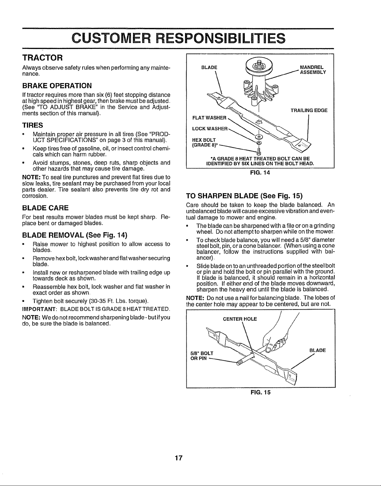
BLADE REMOVAL (See Fig. 14)
= Raise mower to highest position to allow access to
blades..
= Remove hex bolt, lock washer and flat washer securing
blade.
° install new or resharpened blade with trailing edge up
towards deck as shown.
° Reassemble hex bolt, lock washer and flat washer in
exact order as shown..
• Tighten bolt securely (30-35 Ft, Lbs,.torque).
IMPORTANT: BLADE BOLT ISGRADE 8 HEATTREATED.
NOTE: We do not recommend sharpening blade- but ifyou
do, be sure the blade is balanced..
BLADE
MANDREL
ASSEMBLY
\
TRAILING EDGE
HEX BOLT
(GRADE
*A GRADE 8 HEAT TREATED BOLT CAN BE
IDENTIFIED BY SIX LINES ON THE BOLT HEAD.
FIG. 14
TO SHARPEN BLADE (See Fig. '15)
Care should be taken to keep the blade balance& An
unbalanced blade will cause excessive vibration and even-
tual damage to mower and engine.
. The blade can be sharpened with a file or on agrinding
wheel Do not attempt to sharpen while on the mower.
o To check blade balance, you will need a 5/8" diameter
steel bolt, pin, ora cone balancer. (When using a cone
batancer, follow the instructions supplied with bal-
anceO.
, Slide blade on to anunthreaded portion of the steel bolt
or pin and hold the bolt or pin parallel with the ground.
If blade is balanced, it should remain in a horizontal
position° If either end of the blade moves downward,
sharpen the heavy end until the blade is balanced.
NOTE: Do not use a nail for balancing blade. The lobes of
the center hole may appear to be centered, but are not.
CENTER HOLE ///
17
FIG. 15
Page 18
CU SIBILITiES
.................................................. ,11111 iii iii iiiii i
BATTERY
Your tractor has a battery charging system which is suffi-
cient for normal use+ However, periodiccharging of the
battery with an automotive charger will extend its life+
• Keep battery and terminats clean.
- Keep battery bolts tight,
• Keep small vent holes open.
o Recharge at 6-10 amperes for 1 hour.
TO CLEAN BATI'ERY AND TERMINALS
Corrosion and dirt on the battery and terminals can cause
the battery to "leak" power,,
° Open battery box door,
• Disconnect BLACK battery cable first then RED bat-
tery cable and remove battery from tractor:
= Rinse the battery with plain water and dry,+
° Clean terminals and battery cable ends with wire brush
until bright,,
• Coat terminals with grease or petroleum jelly,.
= Reinstall battery (See "CONNECT BATTERY" in the
Assembly section of this manual).
V-BELTS
Check V-beEtsfor deterioration and wear after 100hours of
operation and replace if necessary+ The belts are not
adjustable, Replace belts if they begin to slip from wear°
TRANSAXLE COOLING
The fan and cooling fins of transmission shouJd be kept
clean to assure proper cooling,.
Do not attempt to clean fan or transmission while engine is
running or while the transmission is hot,
° Inspect cooling fan to be sure fan blades are intact and
clean,,
• Inspect cooling fins for' dirt, grass clippings and other
materials. To prevent damage to seals, do not use
compressed air+or high pressure sprayer to clean
cooling fins,.
TRANSAXLE PUMP FLUID
The transaxle was sealed at the factory and fluid mainte-
nance isnot required forthe life of thetransaxle, Should the
transaxle ever leak or require servicing, contact you r near-
est authorized service center/department,,
ENGINE
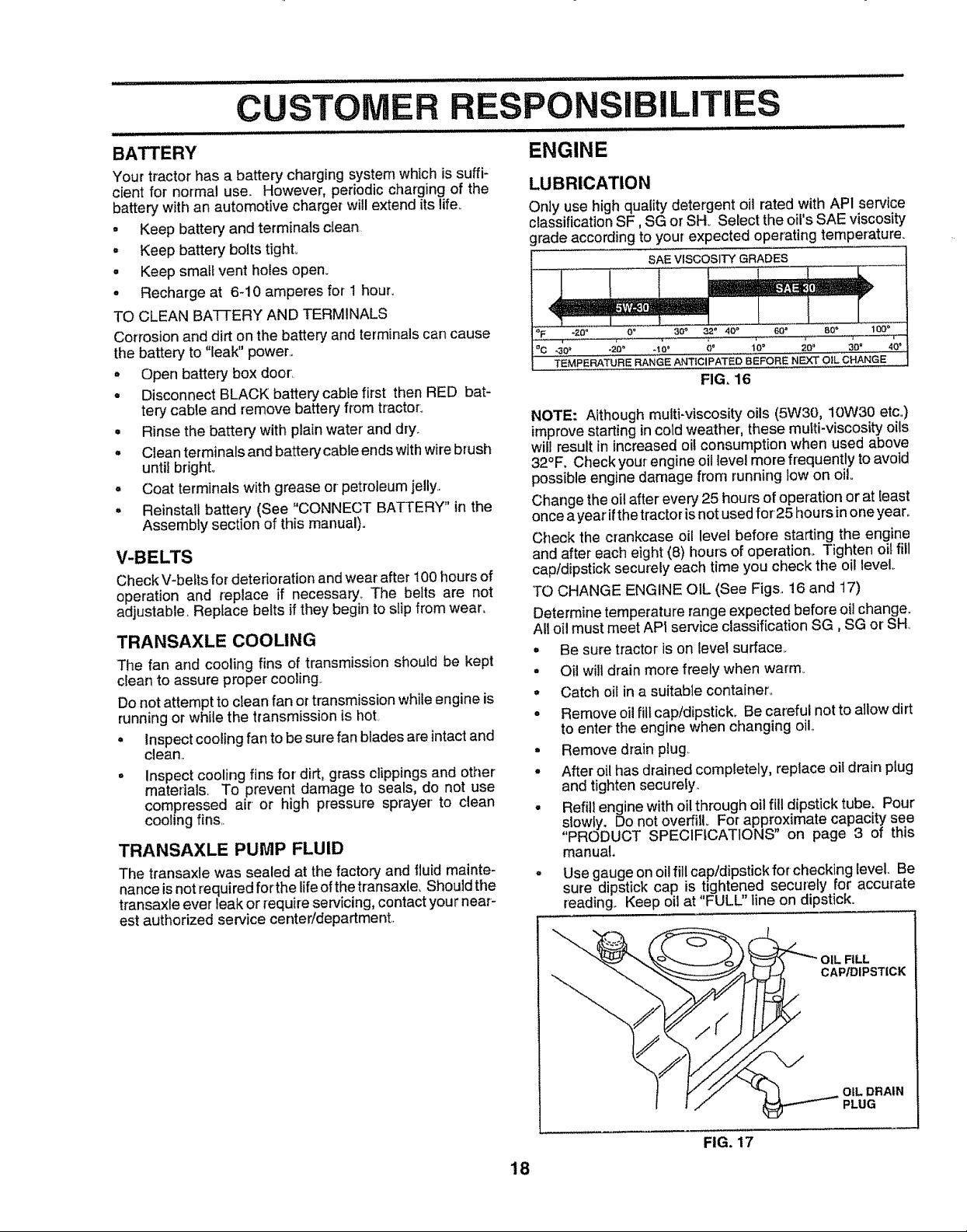
LUBRICATION
Only use high quality detergent oil rated with AP! service
classification SF, SG or SH+ Select the oil's SAE viscosity
grade according to your expected operating temperature+
SAE VISCOSITY GRADES
•30 '+ +20_ -10" 10" 20+ 30" 40+
TEMPERATURE RANGE ANTICIPATED BEFORE NEXT OiL CHANGE
FIG. 16
NOTE: Although multi-viscosity oils (5W30, 10W30 etc,)
improve starting in cold weather, these mufti-viscosity oils
will result in increased oil consumption when used above
32°F. Check your-engine oil level more frequently to avoid
possible engine damage from running low on oil+
Change the oil after every 25 hours of operation or at least
once ayear'if the tractor isnot used for25 hours in one year.
Check the crankcase oil level before starting the engine
and after each eight (8) hours of operation,, Tighten oil fill
cap/dipstick securely each time you check the oil level
TO CHANGE ENGINE OIL (See Figs, 16 and 17)
Determine temperatu rerange expected before oi! change.
All oil must meet API service classification SG, SG or SH
• Be sure tractor is on level surface,.
• Oil will drain more freely when warm,
° Catch oil in a suitable container,.
o Remove oil fill cap/dipstick. Be careful not to allow dirt
to enter the engine when changing oil,,
• Remove drain plug
o After oil has drained completely, replace oil drain plug
and tighten secureiy,
• Refill engine with oil through oil fill dipstick tube. Pour
slowly. Do not overfill For approximate capacity see
"PRODUCT SPECIFICATIONS" on page 3 of this
manual.
° Use gauge onoil fill cap/dipstick for checking level, Be
sure dipstick cap is t+ghtened securely for accurate
reading+ Keep oil at "FULL" line on dipstick.
18
CAP/DIPSTICK
OIL DRAIN
PLUG
FIG. 17
Page 19

CUSTOMER R
I III I I I I I I II I I II 'I III'I IIII'IIIIII'II'I'I I II I I_I I'I'UII]II]I I ' III IIII LLI II IIIII_IL II_ LI 'I'
AIR FILTER (See Fig+ 18)
Your engine will not run properly using a dirty air filter,
Clean the foam pre-cleaner after every 25 hours of opera-
tion or every season.. Service paper cartridge ever,.#100
hours of operation or every season, whichever occurs first.
Service air cleaner more often under dusty conditions.
- Remove knob(s) and cover.
TO SERVICE PRE-CLEANER
° Slide foam pre-cleaner off cartridge.
• Wash it in liquiddetergent and water
• Squeeze it dry in a clean cloth+
• Saturate it in engine oil.. Wrap it in clean, absorbent
cloth and squeeze to remove excess oil
• If very dirty or damaged, replace pre-cleaner..
• Reinstall pre-cleaner over cartridge,.
° Reinstall cover and secure with knob(s)°
TO SERVICE CARTRIDGE
o Remove cartridge nut+
• Carefully remove cartridge to prevent debris from
entering carburetor+ Clean base carefully to prevent
debris from entering carburetor
° Clean cartridge bytapping gently on fiat surface. Ifvery
dirty or damaged, replace cartridge°
° Reinstall cartridge, nut, precleaner, cover and secure
with knob(s).
IMPORTANT: PETROLEUM SOLVENTS, SUCH AS
KEROSENE, ARE NOT TO BE USED TO CLEAN THE
CARTRIDGE,. THEY MAY CAUSE DETERIORATION OF
THE CARTRIDGE DO NOT OIL CARTRIDGE.. DO NOT
USE PRESSURIZED AIR TO CLEAN OR DRY
CARTRIDGE.
PO BILITIES
i ii i iiiii i ii L i iii ii ii i i I
CLEAN AIR SCREEN (See Fig. 19)
Air screen must be kept free of dirt and chaff to prevent
engine damage from overheating. Clean with a wirebrush
or compressed air to remove dirt and stubborn dried gum
fibers°
ENGINE COOLING FINS (See Fig. 19)
Remove any dust, dirt or oil from engine cooling fins to
prevent engine damage from overheating_
, Remove screws from blower housing and lift housing
and dipstick tube assembly off engine
, Cover oil fill opening to prevent entry of dirt.
• Use compressed air or stiff bristle brush to thoroughly
clean engine cooling fins_
° To reassemble, reverse above procedure..
SCREWS BLOWER
DIPSTICK
TUBE
ASSEMBLY
HOUSING
AIR SCREEN
PLUG
COVER KNOB-'--__
COVER CARTRIDGE NUT
PAPER
CARTRIDGE
FIG. 18
ENGINE COOLING FINS
FIG, 19
19
Page 20

CUSTOMER RESPONSI ILITIES
ii iJ_,l ,i .......
MUFFLER
inspectand replace corroded muffler and spark arrester (if
equipped) as it could create a fire hazard and/or damage,.
SPARK PLUGS
Replace spark plugs at the beginning of each mowing
season or' after every 100 hours of operation, whichever
occurs first. Spark plug type and gap setting are shown in
"PRODUCT SPECIFICATIONS" on page 3 of this rnanual.
IN-LINE FUEL FILTER (See Fig. 20)
The fuel filter should be replaced once each season_ Iffuel
filter becomes clogged, obstructing fuel flow to carburetor,
replacement is required..
= With engine coo!, remove filter' and plug fuel line
sections..
= Place new fuel filter in position infuel line with arrow
pointing towards carburetor.,
o Be sure there are no fuel line leaks and clamps are
properly positioned..
• Immediately wipe up any spilled gasoline°
CLAMP
FUEL
FILTER
FIG. 20
CLEANING
° Clean engine, battery, seat, finish, etco of all foreign
rnatter_
• Keep finished surfaces and wheels free of allgasoline,
oil, etc_
• Protect painted surfaces with automotive type wax_
We do not recommend using a garden hose to clean your
tractor unless the electrical system, muffler, air fitter and
carburetor are covered to keep water-out, Water inengine
can result in a shortened engine life.
20
Page 21

...................... ii, i i
SERVICE AND ADJUSTMENTS
...................i,illlll i ii ill_l ii iiiiii illl,ll]l...... illll, ,,,i i i i i,,i,,lllll, l,,llll,,,i,
CAUTION: BEFORE PERFORMING ANY SERVICE OR ADJUSTMENTS:
° Place motion control lever in nelJtral (N) position.
o Depress clutch/brake pedal fully and set parking brake°
° Place attachment clutch in "DISENGAGED" position.
° Turn ignition key "OFF" and remove key,,
. Make sure the blades and all moving parts have completely stopped.
Disconnect spark plug wire from spark plug and place wire where it cannot come in contact
with plug.
.................................... ......................... i i ii i i i ii L, ii ll,llll i, i i i ,ll i
TRACTOR
TO REMOVE MOWER (See Fig. 21)
Mower will be easier to remove from the right sideof tractor_
• Place attachment clutch in "DISENGAGED" position
° Move attachment lift leverforward to lower mower to its
lowest position_
• Roll belt off engine pulley.
• Disconnect clutch rod from clutch lever by removing
retainer spring.
- Disconnect anti-sway bar from chassis bracket by
removing retainer spr=ng,
= Disconnect suspension arms from rear deck brackets
by removing retainer springs°
° Disconnect front links from deck by removing retainer
springs_
° Raise lift lever to raise suspension arms. Slide mower
out from under tractor_
IMPORTANT: IF ANATTACHMENT OTHER THAN THE
MOWER IS TO BE MOUNTED TO THE TRACTOR, THE
R.H. ANDL..H,SUSPENSION ARMS MUST BE REMOVED
FROM TRACTOR.
TO INSTALL MOWER (See Fig. 21)
• Raise attachment lift lever to its highest position,
o Slide mower under tractor with discharge guard to right
side of tractor.
- Lower liftlever to its lowest position°
• Install mower in reverse order of removal instructions.
RETAINER
SPRING
ANTI-SWAY BAR
RETAINER
SPRINGS
(BOTH SIDES)
FIG. 21
21
Page 22

SERVICE AND ADJUSTMENTS
TO LEVEL MOWER HOUSING
Adjust the mower while tractor is parked onlevel ground or
driveway. Make sure tires are property inflated (See
"PRODUCT SPECIFICATIONS" on page 3 ofthis manual).
Iftires are over'or underinflated, youwill notpropedyadjust
your-mower_
SIDE-TO-SIDE ADJUSTMENT (See Figs. 22 and 23)
• Raise mower to its highest position..
° Atthe midpoint of both sides of mower, measure height
from bottom edge of mower to ground_ Distance"A" on
both sides of mower should be the same or'within 1/4"
of each other.
= If adjustment is necessary, make adjustment on one
side of mower only.
• To raise one side of mower, tighten lift link adjustment
nut on that side.
° To lower one side of mower, loosen lift link adjustment
nut on that side.
NOTE: Each full turn of adjustment nut will change mower
height about 1/8'L
° Recheck measurements after adjusting.
BOTTOM EDGE BOTTOM EDGE
OF MOWER TO OF MOWER TO
GROUND GROUND
GROUND LINE A
i iii HlIH','llll'l I I =l=l=,l==l
FRONT-TO-BACK ADJUSTMENT (See Figs° 24 and 25)
IMPORTANT: DECK MUST BE LEVEL SIDE-TO-SIDE. IF
THE FOLLOWING FRONT-TO-BACK ADJUSTMENT IS
NECESSARY, BESURETO ADJUST BOTH FRONT LINKS
EQUALLY SO MOWER WILL STAY LEVEL SIDE-TO-
SIDE
To obtain the best cutting results, the mower housing
should be adjusted so that the front isapproximately I/8"
to 1/2" lower than the rear'when the mower is in its highest
position.
Check adjustment on rightside of tractor'. Measure dis-
tance"D" directly infront and behind the mandrel at bottom
edge of mower housing as shown.
= Before making any necessary adjustments, checkthat
both front links are equal in length. Both links should
be approximately 10-3/8".
. If links are not equal in length, adjust one link to same
length as other' link..
° To lower front of mower loosen nut "E" on both front
links an equal number of turns.
° When distance "D" is 1/8" to 1/2" lower at front than
rear, tighten nuts "F" against trunnion on both front
links.
° To raisefront ofmower, loosennut"F" from trunnionon
both front links. Tighten nut "E" on both front links an
equal number of turns,
° When distance "D" is 1/8" to t/2" lower at front than
rear,tighten nut"F" against trunnion on both front links..
° Recheck side-to-side adjustment.
\\
MANDREL
FIG, 22
SUSPENSION
ARM
FIG. 23
FIG. 24
BOTH FRONT LINKS MUST BE EQUAL IN LENGTH
LIFT LINK
ADJUSTMENT NUT
NUT "E"
NUT "F"
FRONT LINKS TRUNNION
22 FIG. 25
Page 23

SERVICE AND ADJUSTMENTS
TO REPLACE MOWER BLADE DRIVE BELT
(See Fig. 26)
The mower bladedrive belt may be replaced withouttools,
Park the tractor on level surfacer Engage parking brake,
BELT REMOVAL-
° Remove mower from tractor (See "TO REMOVE
MOWER" in this sectionof this manual).
° Work belt offbothmandrel pulleysand idler puIleyso
° Pull belt away from mower.,
BELT INSTALLATION
° Install new beetin reverse order of removal,
o Make sure beltisinall puiteygrooves and insideallbelt
guides°
° Install mower inreverse order of removal instruction&,
MANDREL IDLER
PULLEY PULLEYS
MANDREL
PULLEY
FIG, 26
TO ADJUST BRAKE (See Fig. 27)
Your tractor is equipped with an adjustable brake system
which is mounted on the side of the transaxle.
Iftractorrequires more than six (6) feet stopping distance
at high speed inhighest gear, then brake must be adjusted.
• Depress clutch/brake pedal and engage parking brake°
° Measure distance between brake operating arm and
nut "A" on brake rod.
if distance isother than 1-3/4", loosen jam nut and turn
nut "A" until distance becomes 1-3/4". Retighten jam
nut against nut "A".
Road test tractor for proper stopping distance as stated
above. Readjust if necessary. If stopping distance is
still greater than six (6) feet in highest gear, further
maintenance isnecessary. Contact your nearest au-
thorized service center/departmenL
ii,,i,l,ll,lll,l,l,i,illll,llllllllllllllllllli i L
WITH PARKING BRAKE "ENGAGED"
NUT "A"
JAM NUT
ARM
DO NOT TOUCH THIS NUT, IF FURTHER
BRAKE ADJUSTMENTIS NECESSARY
CONTACT YOUR NEAREST AUTHORIZED
SERVICE CENTER_EPARTMENT
FIG, 27
TO REPLACE MOTION DRIVE BELT
(See Fig. 28)
Park the tractor on level surface. Engage parking brake,
For assistance, there is a belt installationguide decal on
bottom side of left footrest.
• Remove mower (See "TO REMOVE MOWER" in this
section of this manuaL)
o Remove upper belt keeper°
° Remove belt from stationary idler and clutching idler,
° Pull belt slack toward rear of tractor. Carefully remove
belt upwards from transmission inputpulley and over
cooling fan blade&
• Pull belt toward front of tractor and remove downward
from around engine pulley.
• Install new belt by reversing above procedure_
IMPORTANT; MAKE SURE UPPER BELT KEEPER IS
POSITIONED PROPERLY BETWEEN LOCATOR TABS.
ENGINE "----_.._.._it
PULLEY _r*_,.,._ it-- LOCATOR
I_-;'T_,L_J_ _,.-" "'TABS
CLUTCHING _L--I_["
' "_ UPPER BELT
STATIONARY_ I KEEPER
IDLER !1 _
TRANSMISStON._,_,r _.,."_
23
FIG. 28
Page 24

CE
TO ADJUST MOTION CONTROL LEVER (See
Fig. 29)
The motion control lever has been preset atthe factory and
adjustment should not be necessary'.
If for any reason the motion control lever will not hold its
position while at a seJectedspeed, it maybe adjusted atthe
friction pack located on the rightside of transmission.
• Park tractor on level surface, Stop tractorby turning
ignition key to "OFF" position, and engage parking
brake,,
o Adjust motion control lever by tightening adjustment
Iocknut one half (1/2) turn.
NOTE: If for any reason the effort to move the motion
control lever becomes too excessive, reverse the above
adjustment procedure by loosening !ocknut 1/4 to 1/2tum_
Road test tractor after adjustment and repeat procedure if
necessary,.
TRANSMISSION REMOVAL/REPLACEMENT
Should your transmission require removal for service or
replacement, it should be purged after reinstallation and
before operating the tractor. See "PURGE TRANSMIS-
SION" in the Operation section of this manual
ADJUSTMENTS
i i i,, i,i _ ............................ i
TO REMOVE WHEEL FOR REPAIRS
(See Fig. 30)
= Block up axle securely.
° Remove axle cover, retaining ringand washers to allow
wheel removal (teatwheel contains a square key - Do
not lose).
° Repair' tire and reassemble.
, On rear wheels only: align grooves in rear wheel hub
and axle. Insert square key.
° Replace washers and snap retaining ring securely in
axle groove.
• Replace axle cover_
NOTE: To seal tire punctures and prevent flat tires due to
slow leaks, tire sealant may be purchased from your local
parts dealer. Tire sealant also prevents tire dry rot and
corrosion,
WASHERS
RETAINING
R_NG
ADJUSTMENT
LOCKNUT
FIG. 29
TO ADJUST STEERING WHEEL ALIGNMENT
If steering wheel crossbars are not horizontal (left to right)
when wheels are positioned straight forward, remove steer-
ing wheel and reassemble per instructions in the Assembly
section of this manual.
FRONT WHEEL TOE-IN/CAMBER
The front wheel toe-in and camber-are not adjustable on
your tractor.. If damage has occurred to affect the front
wheel toe-in or camber, contact your nearest authorized
service center/departmento
AXLE COVER
(REAR WHEEL ONLY)
FIG, 30
TO START ENGINE WITH A WEAK BATTERY
(See Fig, 31)
CAUTION: Lead-acid batteries gener-
ate explosive gases. Keep sparks, flame
and smoking materials away from bat-
I IIIIIIIIIIII ,j iii1!1111 II IIIII III IIIIUI IIIII III I IIII
if your battery is too weak to start the engine, it should be
recharged° If "jumper cables" are used for' emergency
starting, follow this procedure:
IMPORTANT; YOUR"TRACTORIS EQUIPPED WITH A 12
VOLT NEGATIVE GROUNDED SYSTEM, THE OTHER
VEHICLE MUST ALSO BE A 12 VOLT NEGATIVE
GROUNDED SYSTEM. DO NOT USE YOUR TRACTOR
BATTERY TO START OTHER VEHICLES.
TO ATTACH JUMPER CABLES -
• Connect each end of the RED cable to the POSITIVE
(+) terminal of each battery, taking care not to short
against chassis.
• Connect one end of the BLACK cable to the NEGA-
TIVE (-) terminal of fully charged battery.
= Connect the other end of the BLACK cable to good
CHASSIS GROUND, away from fuel tank and battery°
teries, Always wear eye protection
when around batteries.
......... i ,lllll ii i,,i,, i i _,J
24
Page 25

SERVICE AND ADJU ENTS
TO REMOVE CABLES, REVERSE ORDER -
- BLACK cable first from chassis and then fromthe fully
charged battery°
- RED cable last from both batteries,,
POSITIVE TERMINAL NEGATIVE TERMINAL
\
/HOOD
HEADLIGHT
\
FIG. 32
CABLES
CHARGED
BATTERY
POSITIVE TERMINAL
FIG. 31
\
NEGATIVETERMINAL
TO REPLACE HEADLIGHT BULB
. Raise hood.,
o Pull bulb holder out of the hole inthe backside of the
grill.
° Replace bulb in holder and push bulb holder securely
back into the hole in the backside of the grill,,
o Close hood°
INTERLOCKS AND RELAYS
Loose or damaged wiring may cause your tractor to run
poorly, stop running, or prevent it from starting,
o Check wiring. See electrical wiring diagram in the
Repair Parts section of this manual,
TO REPLACE FUSE
Replace with 30 amp automotive-type plug-in fuse_ The
fuse holder is located behind the dash,
ENGINE
TO ADJUST THROTTLE CONTROL CABLE
(See Fig. 33)
The throttle control has been preset at the factory and
adjustment should not be necessary° Check adjustment as
described below before loosening cable_ tf adjustment is
necessary, proceed as follows:
° With engine not running, move throttle control lever
from slow to choke position. Slowly move lever from
choke to fast position.
° Checkthat holes"A" ingovernor control lever andhole
in governor plate line-up., If holes "A" are not aligned,
Ioosenclampscrewand move throttle cable until holes
are aligned, Tighten clamp screw securely.
GOVERNOR GOVERNOR
CONTROL LEVER CONTROL PLATE
TO REMOVE HOOD AND GRILL ASSEMBLY
(See Fig. 32)
. Raise hood,
° Unsnap headlight wire connector,
° Stand infront oftractor, Grasp hood at sides, tilt toward
engine and lift off of tractor.
° To replace, reverse above procedures,
25
HOLES"A"
CLAMP THROTTLE
SCREW CABLE
FIG, 33
Page 26

TO ADJUST CARBURETOR (See Fig. 34)
The carburetor has been preset at the factory and adjust-
ment should not be necessary° However, minor adjust-
merit maybe required to compensate fordifferences infuel,
temperature, altitude or load. If the carburetor does need
adjustment, proceed as follows:
In general, turning idle mixture valve in (clockwise) de-
creases the supply of fuel tothe engine giving a teaner fuel/
air' mixture. Turning the idle mixture valve out (counter-
clockwise) increasesthe supply of fuel to the engine giving
a richer fuel/air mixture..
IMPORTANT: DAMAGE TO THE NEEDLE VALVE AND
THE SEAT IN CARBURETOR MAY RESULT IF SCREW tS
TURNED IN TOO TIGHT°
PRELIMINARY SETTING -
= Air cleaner assembly must be assembled to the carbu-
retor when making carburetor adjustments..
= Be sure the throttle control cable is adjusted properly
_seeabove_..
° With engine off turn idle mixture valve in (clockwise)
closing it finger tight and then turn out (counterclock-
wise) 1 full turn.
FINAL SETTING -
• Start engine and allow to warm for'five minutes. Make
final adjustments with engine running and shift/motion
control lever' in neutral (N) position°
o Move throttte control lever'to slow position_With finger,
rotate and hold throttle lever against idlespeed screw.
Turn idle speed screw to attafn 1750 RPM
• While still holding throttle lever against idte speed
screw, turn idle mixture valve in (clockwise) until en-
gine beginsto die and then turn out (counterclockwise)
until engine runs rough Turn valve to a point midway
between those two positions. Release throttle lever'.
ACCELERATION TEST -
• Move throttle control lever from stow to fast position., if
engine hesitates or dies, turn idle mixture valve out
(counterclockwise) 1/8 turn. Repeat test and continue
to adjust, if necessary, until engine accelerates
smoothly.
High speed stop is factory adjusted° Do not adjust -
damage may resulL
IMPORTANT: NEVER TAMPER WITH THE ENGINE
GOVERNOR, WHICH IS FACTORY SET FOR PROPER
ENGINESPEED. OVERSPEEDtNGTHE ENGINE ABOVE
THE FACTORY HIGH SPEED SETTING CAN BE
DANGEROUS. _FYOU THINK THE ENGINE-GOVERNED
HIGH SPEED NEEDS ADJUSTING, CONTACT YOUR
NEAREST AUTHORIZED SERVICE CENTER/
DEPARTMENT, WHICH HAS PROPER EQUIPMENT AND
EXPERIENCE TO MAKE ANY NECESSARY
ADJUSTMENTS.
THROTTLE IDLE SPEED
I
LEVER SCREW
26
IDLE MIXTURE
VALVE
FIG. 34
Page 27

Immediately prepare your tractor for storage at the end of
the season or if the tractor will not be used for 30 days or
more.
CAUTION: Never store the tractor with
gasoline in the tank inside a building
where fumes may reach an open flame
or spark. Allow the engine to cool
before storing in any enclosure.
TRACTOR
Remove mower from tractor for winter storage, When
mower is to be stored for a period of time, clean it thor-
oughly, remove all dirt, grease, leaves, etc. Store in a
clean, dry area_
• Clean entire tractor (See "CLEANING" in the Customer
Responsibilities section of this manual),.
• Inspect and replace belts, if necessary (See belt re-
placement instructions in the Service and Adjustments
section of this manual),
• Lubricate as shown in the Customer Responsibilities
section of this manual.
- Be sure that all nuts, bolts and screws are securely
fastened. Inspect moving parts for damage, breakage
and wear., Replace if necessary°
• Touch up all rusted or chipped paint surfaces; sand
lightly before painting.
BATTERY
° Fully charge the battery for storage.
. After a period of time in storage, battery may require
recharging,.
• To help prevent corrosion and power leakage during
long periods of storage, battery cables should be
disconnected and battery cleaned thoroughly (see'q'O
CLEAN BATTERY AND TERMINALS" in the Cus-
tomer Responsibilities section of this manual).
• After cleaning, leave cables disconnected and place
cables where they cannot come in contact with battery
terminals,
• Be sure battery drain tube issecurely attached,
• If battery is removed from tractor for storage, do not
store battery directly on concrete or damp surfaces.
ENGINE
FUEL SYSTEM
IMPORTANT: IT kS IMPORTANT TO PREVENT GUM
DEPOSITS FROM FORMING IN ESSENTIAL FUEL
SYSTEM PARTS SUCH AS CARBURETOR, FUEL FILTER,
FUEL HOSE, OR TANK DURING STORAGE. ALSO,
EXPERIENCE INDICATES THAT ALCOHOL BLENDED
FUELS (CALLED GASOHOL OR USING ETHANOL OR
METHANOL) CAN ATTRACT MOISTURE WHICH LEADS
TO SEPARATION AND FORMATION OF ACIDS DURING
STORAGE. ACIDIC GAS CAN DAMAGE THE FUEL
SYSTEM OF AN ENGINE WHILE tN STORAGE.
o
Drain the fuel tank_
• Start the engine and let it run untii the fuel lines and
carburetor are empty.
• Never use engine or carburetor cleaner products inthe
fuel tank or permanent damage may occur_
• Use fresh fuel next season.
NOTE: Fuel stabilizer is an acceptable alternative in
minimizing the formation of fuel gum deposits during stor-
age,. Add stabilizer to gasoline in fuel tank or storage
container, Always follow the mix ratio found on stabilizer
container. Run engine at least 10 minutes after adding
stabilizer to allow the stabilizer to reach the carburetor. Do
not drain the gas tank and carburetor if using fuel stabilizer.
ENGINE OIL
Drain oil (with engine warm) and replace with clean engine
oil. (See "ENGINE" in the Customer Responsibilities
section of this manual)_
CYLINDERS
° Remove spark plug(s),,
° Pour one ounce of oil through spark plug hole(s) into
cylinder(s).,
° Turn ignition keyto"START"position fora few seconds
to distribute oil.
Replace with new spark plug(s).
OTHER
, Do not store gasoline from one season to another°
o Replace your gasoline can if your can starts to rust.
Rust and/or dirt in your gasoline wilt cause problems.
• If possible, store your tractor indoors and cover it to
give protection from dust and dirt.
• Coveryourtractorwith asuitable protective cover that
does not retain moisture. Do not use plastic. Plastic
cannot breathe which allows condensation to form and
will cause your tractor to rust.
IMPORTANT: NEVER COVERTRACTOR WHILE ENGINE
AND EXHAUST AREAS ARE STILL WARM,
27
Page 28

......... ii
NG POINTS
PROBLEM
Will not start
Hard to start
Out of fuel
Engine not "CHOKED" properly
Engine flooded,
Bad spark plug
Dirty air {liter.
Dirty fuel filter,,
Water in fuel
Loose or damaged wiring..
Carburetor out of adjustmenL
Dirty air tilter
Bad spark plug
Weak or dead battery
Dirty fuel filter.
Stale or dirty fuel.
Loose or damaged winng
Carburetor out of adjuslment
8 Engine valves out of adjustment
CLutch/brakeperle{ not depressed,
Attachment clutch is engaged
Weak or dead battery,
Blown fuse
Corroded battery terminals
Loose or damaged wiring
Faulty ignition switch
Faulty solenoid or starter
Faulty operator presence switch(as)
CORRECTION
1,, Fill fuel tank.
2. See "TO START ENGINE" in Operation section
3. Wait several m{nutes before attempting to start,.
4, Replace spark plug.
5, Clean/replace air filter,
6, Replace fuel filter_
7,, Drain fuel tank and carburetor, refill lank with fresh
gasoline and replace fuel filter,
8. Check all wiring.
9, See "To Adjust Carburetor" in Service Adjustments
seclion.
10, Contact an authorized service centeddepartment.
1 Clean/replace air fittar,
2. Replace spark ptug
3. Recharge or replace battery.
4 Replace fuel filter..
5. Drain fuel tank and refillwith fresh gasoline,
6_ Check all wiring.
"7 See "To Adjust Carburetor" in Service Adjustments
section.
8, Contact an authorized service center/department
ill
1 Depress clutch/brake pedal,
2 Disengage attachment clutch
3 Recharge or _eplace battery,.
4, Replace fuse
5 Clean batter:! terminals,.
6. Check all wiring
7, Check/replace ignition switch
8, Check/replace solenoid or starter,
9 Contact an authorized service centeddepartment,
Engine clicks but will not
start
Loss of power
Excessive vibration
Weak or dead battery,
Corroded battery terminals
Loose or damaged wiring
Faulty solenoid or starter,
Cutting too much grass/too fast
Throttle in "CHOKE" position.
Build-up of grass, leaves and trash under mower,.
Dirty atr filter.
Low oil level/dirty oil.,
Faulty spark plug,
Dirty fuel filter
Stale or dirty fuel
Water in fuel.
Spark plug wire loose,
Dirty engine air screen/fins
D_rty/clogged muffler,
Loose or damaged wiring
Carburetor out of adjustment..
Engine valves out of adjustment,
...... JLll_=
Worn, bent or loose blade
Bent blade mandrel.
Loose/damaged part(s),
1 Recharge or replace battery,
2 Clean battery terminals,
3, ChsckalIwIrtng.
4, Check/replace solenoid or starter
!. Set in "Higher Cut" position!reduce speed
2 Adjust throttle control,
3 Clean underside of mower housing,
4. Clean/replace air' filter
5 Check oil level/change oil
6 Clean and regap or change spark plug
7, Replace fuel filter
8, Drain fuel tank and refill with fresh gasoline.
9 Drain fuel tank and carburelor, refill tank with fresh
gasoline and replace fuel filter,.
10. Connect and tighten spark plug wire,
tt, Clean engine air screen/fins,
12 Cleanlrepiace muffler
13, Check all wiring,
14, See "To Adjust Carburetor" in Service Adjustments
section.
t5, Contact an authodzed service center!department
1, Replace blade,. Tighten biade bolt
2, Replace blade mandrel.
3 Tighten loose part(s) Replace damaged parts
28
Page 29

TROUBLESHOOTING
POINTS
PROBLEM
Engine continues to run
when operator leaves seat
with attachment clutch
engaged
.......... , ,, ,,,,,,,,,ulul
Poor cut _uneven
Mower blades will not
rotate
Poor grass discharge
CAUSE
I., Faulty operator-safety presence control system t
1,. Worn, bent or loose blade..
2. Mower deck not leve!
3. Bu{ldup of grass, leaves, and trash under mowe[
4. Bent blade mandrel
5. Clogged mower deck vent holes from buildup of
grass, leaves, and trash around mandrels.
i
1. Obstruction In clutch mechanism,
2_ Worn/damaged mower drive belt..
3. Frozen idier pulley.
4. Frozen blade mandrel.
1o Eng{ne speed too slow.
2. Travel speed too fast..
3, Wet grass,
4.. Mower deck not level.
5, Low/uneven ttre air pressure
6. Worn, bent or loose blade
7. Buildup of grass, leaves and trash under mower
8. Mower drive belt worn
9. Blades improperly instal{ed
10.. Improper blades used
t"f, Clogged mower deck vent holes from buildup of
grass, {eaves, and trash around mandrels.
CORRECTION
Check wiring, switches and connections If not
corrected, contact an authorized service center/
department,
1. Replace blade. Tighten blade bolt.
2. Level mower deck,
3. Clean underside of mower housing
4. Replace blade mandrel
5. Clean around mandrels to open vent holes
1 Remove obstruction
2 Replace mowerdrive belt,
3 Replace idler pulley,
4 Replace blade mandrei.
1 Place throttta control in "FAST" position.
2 Shift to slower speed..
3 Alfow grass to dry before mowing
4. Level mower deck.
5. Checktires for proper air pressure.,
6 Replace/sharpen blade Tighten blade boit.
7. Clean underside of mower housing
8 RepIace mower ddve belt..
9 Reinstall blades sharp edge down.
10 Replace with blades listed in this manual.
t 1 Clean around mandrels to open vent holes
Headlight(s) not working
(if so equipped)
i tllllll i u i n iiiiiiiii
Battery will not charge
Loss of drive
nil i i ull,i
Engine "backfires"
when turning engine
"OFF"
"f. Switch is "OFF"
2 Bulb(s) burnedout
3 Fautty Iight switch
4., Loose or damaged wiring
5 Blown fuse,
1 Bad battery cell(s)
2 Poor cable connections
3. Faulty regulator (if so equipped)
4 Faulty alternator.
1. Freewheel control in "disengaged" position
2. Motion drive bert worn, damaged, or broken,,
3. Air trapped in transmission during shipment
or servicing.
i i
1. Engine throttlecontrol not set at "SLOW"
position for 30 seconds before stopping engine.,
1 Turn switch "ON"
2 Reptace bulb(s)
3. Check/replace light switch.,
4, Checkwirtng and connections
5 Replace fuse
t Replace battery
2 Check!clean all connections,
3 Replace regulator
4 Replace alternator
1 Place freewheel control tn "engaged" position,
2 Replace motion drive belt
3 Purge transmission
t Move throttle control to "SLOW" position and allow
to idIe for 30 seconds before stopping engine
29
Page 30

l lll llll II,,H_I,,,IIHIIH
...... i lllllll i i illl ill iiiill ,i i,l,i M Illl
SERVICE NOTES
i iii , llllllllll,ll i i iii ii ii ii ,
30
Page 31

SCHEMATIC
TRACTOR - - MODEL NUMBER 917.258532
AMMETER
(OPTIONAL)
RED
IGNITION
SWITCH
RED
RED
WHITE
BATTERY
FUSE30 AMP..
t
r-- -- --_ .....
,©
I
CLUTCHL------t-- - J
BRAKE
(PEDALUP)
BLACK
HOUR _ F"
METER
(OPTIONAL)
r UEL l,
I 'A\ LINE t
t j
FUELSHUT-OFF
SOLENOID l
ORANGE
BLACK
RED
STARTER
SOLENOID
WRITE
SEAT SWITCH
(NOT OCCUPIED)
]
1 t I
t I
_A_IT_ENT CL-UT(_H
(CLUTCH OFF) i
I I
I
, p
I
GROUNDING
CONNECTOR D
,1_ SPARK
BLACK
(_ IGNITIONUNIT
TWIN CYL, ENGINES)
CHARGING SYSTEM OUTPUT 28 VOLTS AC MIN, @ 3600 RPM
3 AMP DC O 3600 RPM (CHARGING SYSTEM DISCONNEC't'EO)
BLUE __
UGHT,NGSYSTEM_! ._- _ALTERNATOR I',
5AMpAoo3oooR_Ju= ','_"'_'-'"_"-"."" I!
PLUG
GAP w ......
PLUGS ON
BLACK
k
qP
P
b
IGNITION SWITCH
POSITION CIRCUIT "MAKE"
OFF G + M + L NONE
RUN/LIGHT B + L A + Y
RUN B + L NONE
START B + L + S NONE
z, _ , ,
NOTE
YOUR TRACTOR IS
EQUIPPED WITH A SPECIAL
ALTERNATOR SYSTEM BROWN
THE LIGHTS ARE NOT
CONNECTED TO THE
BATTERY, BUT HAVE THEIR
OWN ELECTRICAL SOURCE
BECAUSE OF THIS, THE
HEADLIGHTS
BRIGHTNESS OF THE LIGHTS
WILL CHANGE WITH ENGINE
SPEED. AT IDLE THE LIGHTS
WILL DIM. AS THE ENGINE IS NON-REMOVABLE
SPEEDED UP, THE LIGHTS CONNECTIONS
WILL BECOME THEIR BRIGHTEST.
REMOVABLE
CONNECTIONS
WIRING INSULATED CLIPS
NOTE: IFWIRING INSULATED CLIPS WERE REMOVED FOR
SERVICING OF UNIT, THEY SHOULD BE REPLACED TO
PROPERLY SECURE YOUR WIRING°
"_ 31
/77
Page 32

REPAIR PARTS
ELECTRICAL
19
TRACTOR-- MODEL NUMBER 917.258532
\!
?
/
/
33
I
/
!
!
/1
32
Page 33

REPAIR PARTS
ELECTRICAL
TRACTOR - - MODEL NUMBER 917.258532
KEY PART
NO. NOr DESCRIPTION
1 146139
2 74760412
3 STD551025
4 8TD551125
6 STD541025
7 I09238X
8 156417
9 109596X
16 153664
19 STD551125
20 73350400
21 147430
22 4152J
24 4799J
25 146147
26 108824X
28 4207J
29 121305X
30 140301
31 t242tlX
32 141226
33 I09310X
40 156442
41 7111O408
42 131563
43 145673
44 73640400
45 121433X
52 141940
70 140422
NOTE: All component dimensions given in U°S. inches
1 inch = 25.4 mm
Battery 12 Volt 25 Amp
Bolt, Hex Head 1/4-20 unc x 3/4
Washer
Washer
Nut
Tube, Plastic, 12"
Case, Battery' Mech Hinge
Clamp, Hose
Switch, |nterlock Push-In
Washer, Lock
Nut, Hex, ,Jam 1/4-20 UNC
Harness, Light Socket
(Includes 4152J)
Bulb, Light
Cable, Battery, 6 Gauge, Red, tl"
Cable, Batten], 6 Gauge, Red, W/t6
Wire
Fuse, 30 Amp
Cable, Ground, 6 Gauge, Black, 12"
Switch, Plunger
Switch, Ignition
Nut, Ignition
Cover, Key Switch
Key, Ignition
Harness, Ignition
Bolt, Hex Head, Fin 1/4-20 x 1/2
Cover, Terminal, Red
Solenoid
Nut Keps Blk Hex 1/4-20 UNC
Ammeter Rectangular 6 Amp
Protection Wire Loop
Harness Engine B&S
33
Page 34

REPAIR PARTS
TRACTOR - - MODEL NUMBER 917.258532
CHASSIS AND ENCLOSURES
28
12
37
6O
3
74
38_ 39
3
13
14
34
Page 35

REPAIR PARTS
TRACTOR - - MODEL NUMBER 917.258532
CHASSIS AND ENCLOSURES
KEY PART
NO. NO. DESCRIPTION
1 159527
2 140356
3 17490612
4 19131216
5 155272
9 150156X011
10 STD533710
11 146956
12 145660
13 146962
14 174906O8
17 144983X558
18 126938X
25 19131312
26 STD541437
28 !45198X558
29 145200
30 t51287X558
31 139976
38 139886
39 139887
51 7380O400
52 19091416
53 145201
54 17030814
55 145202
57 STD522507
60 STD533707
64 154798
71 7368040O
74 STD541437
140 150556
'142 156095
143 154966
144 154207
145 156524
146 154334
147 74760412
-- 5479J
NOTE: All component dimensions given in U.S,.inches
1 inch= 25°4 mm
Chassis Assembly
Drawbar
Screw, Thdo Roll. 3/8-16 x 3/4
Washer 13/32 x 3/4 x 16 Gauge
Bumper Hood/Dash
Dash
Bolt, Carriage 3/8-16 x 3/4
Panel, Dash, LH.
Clip Tinnerman Grille P/L
Panel, Dash, R.Ho
Screw Thdrol 3/8-16 x 1/2
Hood Assembly
Bumper Hood
Washer !3/32 x 13/16 x I2 Gauge
Nut
Grille w/Clips MS-558
Lens, Grilte
Fend/Ftrest Pnt STLT N HLD 558
Bracket, Fender Support
Pivot Bracket Assembly, L.H,.
Pivot Bracket Assembly, R.Ho
Nut Lock w/Insert 1/4-20 UNC
Washer 9/32 x 7/8 x 16 Gao
Bracket Grille Pickoff LH
Screw Spidertock Hex Hd #8-7/8
Bracket Grille Pickoff RH
Bolt, Fin Hex 1/4-20 UNC x .75
Bolt Rdhd Sqnk 3/8-'16 UNC x 314
Dash Lower STLT
Nut, Crownlock 1/4-20 UNC
Nut Crownlock 3/8-16 UNC
Bracket Chassis Front
Plate Reinforcement STLT
Bracket Swaybar Chassis
Bracket Pnt Footrest STLT
Rod Pivot Chassis/Hood
Screw Torx HdThd 5/16-18 UN-2A
Bolt, Hex Hd 1/4-20 UNC x 3/4
Plug, Button
35
Page 36

REPAIR PARTS
DRIVE
TRACTOR - - MODEL NUMBER 917.258532
57
87
72 70
66 116
oo i
\
77
95
3O
103
97
19
91
24
3O
62
22
36
61
32
84
64 f
37
100
27
121
).f 48
118
26
51
106
36
100
Page 37

REPAIR PARTS
TRACTOR - - MODEL NUMBER 917.258532
DRIVE
KEY PART KEY PART
NO, NO. DESCRIPTION NO, NO+ DESCRIPTION
1 t50071 Transaxle Assembly 63 140186
2 142431 Spring, Return, Brake 64 71170764
3 143995 Pulley, Transaxle 65 STD551143
8 154792 Rod Shift Fender 66 154778
10 STD561210 Pin Cotter 1/8 x 1 CAD 69 142432
15 74490544 Bolt Hex Flghd 5/16-t8 Gr+5 70 134683
16 STD541431 Nut Lock HexW/Ins. 5/16-18 Unc 7t 140158
18 STD523710 Bolt Fin Hex 3/8-16 Unc x 1Gr, 5 72 19132012
19 STD541437 Nut Lock Hex W/Wsh 3/8+16 Unc 73 156347
21 130564 Knob, Deluxe 1/2-13 74 121199X
22 145627 Rod, Brake Hydro 75 12t749X
24 73350600 Nut, Hex Jam 3/8-16 Unc 76 12000001
25 106888X Spring, Brake Rod 77 123583X
26 STD551037 Washer 78 121748X
27 76020412 Pin Cotter 1/8 x 3/4 CAD.. 81 156046
28 145204 Rod, Parking Brake 82 123782X
29 124236X Cap, Parking Brake 83 19171216
30 130807 Bracket, Transaxte 84 140548
31 127275X Keeper Belt Lh 86 71208
32 STD523107 Bolt Hex Hd 5/16-I8 Unc x 3/4 87 19212016
34 155071 Shaft, Foot Pedal 88 12000008
35 120183X Bearing, Nylon 89 154882
36 STD551062 Washer 91 74780536
37 STD571810 Pin, Roll 92 74780524
38 123674X Pulley, Idler, Flat 93 142564
39 STD523727 Bolt 94 140462
40 4470J Spacer, Split 95 144643
41 154777 Keeper, Belt Retainer 96 STD624003
42 19131312 Washer 13/32x 13/16x 12 Gauge 97 140469
47 127783 Pulley, Idler, V-Groove 98 73510600
48 154604 Bellcrank Assembly Clutch 100 19111216
49 123205X Retainer, Belt 102 141322
50 STD523715 Bolt 103 73940800
51 STD541437 Nut Crownlock 3/8-16 UNC 104 140156
52 STD541431 Nut, Crownlock 5/16-18 Unc 105 71070516
53 1057t0X Link, Clutch 106 74780520
55 105709X Spring, Return, Clutch 116 72110610
56 STD523712 Bolt Hex 3/8-16x 1-1/4 118 154774
57 140294 V-Belt, Ground Drive 12! 154419
59 140312 Keeper, Center Span
61 17490612 Screw Thdrol 3/8-16 x 3/4 Ty. TT
62 8883R Cover, Pedal
NOTE: All component dimensions given in U+& inches
1 inch = 25.4 mm
Pulley, Engine
Bolt 7/16-20 X 4 Gr+5
Washer Lock HW HIcl Spr 7/I6
Keeper Belt Engine
Screw
Keeper Belt Engine
Strap Torque Lh Hydro t8/20" T
Washer 13/32 x 1-1/4 x 12 Gauge
Strap Torque Rh Hydro
Spacer, Split
Washer 25/32 x 1-1/4 x 16 Gauge
E-Ring
Key, Square
Washer 25/32 x 1-5/8 x 16 Gauge
Shaft Asm..Cross Hydro 20" Tires
ring Torsion T/A
sher 17/32 x 3/4 x 16 Ga+
Rod, Tie Hydro 20" Tires
Bushing Rod Strig_ 629/632 ID
Washer 21/32 x 1-1/4 x 16 Ga,
Ring Klip #5304-62
Console, Shift
Bolt Fin Hex 5/16-18 x 2-'1/4
Bolt Fin Hex 5/6-!8 Unc x 1+1/2
Line Fuel Hydro 4"
Fan, Hydro 7"
Control Bypass Hydro 20" Tires
Retainer Spring 1 Zinc/Cad
Keeper Bolt Rh Hydro 0750, 18/20
Nut Keps He× 3/8-16 Unc
Washer 11/32 x 3/4 x 16 Ga.
Washer Bellville +501D x 1.50D
Nut Hex Jam Toplock 1/4-20 tJnf
Arm, Control Hydro
Screw Cap Hex 5/16 x 18 x 1
Boft Fin Hex 5/16-18 Unc x 1-1/4
Bolt Rdhd Sqnk 3/8-16 x 1.25
Spacer Bellcrank
Nyliner Clutching STL
37
Page 38

REPAIR PARTS
STEERING ASSEMBLY
..::::-t_.\_: ,,
62
TRACTOR - - MODEL NUMBER 917.258532
__41
__36
j1
68 70 13
4O
25
28
lO
30
67
38
Page 39

REPAIR PARTS
STEERING ASSEMBLY
TRACTOR - - MODEL NUMBER 917.258532
KEY PART
NO. NO. DESCRIPTION
t 139768
2 154427
3 156483
4 157473
5 6266H
6 121748X
7 19272016
8 12000029
9 3366R
10 I56438
11 STD551137
13 154779
15 73901000
16 132624
17 156546
18 57O79
19 124035X
20 126684X
21 STD551125
22 71100410
23 127501
25 154406
26 126847X
27 136874
28 19131416
29 17490612
30 STD561210
32 130465
36 155099
37 '152927
38 '139769
39 19133808
40 STD541537
41 't00711L
42 t45054
43 121749X
44 153720
46 121232X
47 6855M
51 STD541431
53 73680600
54 74780520
62 156594
63 STD5237!0
65 154780
66 154404
67 74781044
68 154429
69 160367
7O 74780636
Steering Wheel
Axle Assembly STMP Dropped STL
Spindle Assembly, L.H.
Spindle Assembly, R.H.
Bearing, Race, Thrust, Hardened
Washer 25/32 x 1-5/8 x 16 Gauge
Washer 27/32 x 1-1/4 x t6 Gauge
Ring, Klip
Bearing, Steering Column
Draglink Extended Stamped
Washer, Lock
Bearing Axle STLT!GT
Nut, Lock, Flange 5/8-11 UNC
Pin, Axle 5/8 x ! .55/1.54
Shaft Assembly, Steering
Washer, Thrust .515 x .750 x .033
Support, Shaft
Washer, Shim 1/4 x 518x .062
Washer
Screw, Hex Socket Head
1/4-20 x 5/8
Pitlman Shaft Assembly
Bracket, Steering
Bushing, Link, Drag
Gear, Sector
Washer 13/32 x 7/8 x 16 Gauge
Screw, Thd., Roll, 3/8-16 x 3/4
Pin
Rod, Tie
Bushing, Steering
Screw
Insert, Steering Wheel
Washer 13/32 x 2-3/8 x 8 Gauge
Gripco Nut
Adaptor, Steering Wheel
Boot, Steering Shaft
Washer 25/32 x 1-1/4 x 16 Gauge
Extension Shaft Steering LR.LT
Cap, Spindle
Fitting, Grease
Nut Lock Hex w/Ins. 5/t6-18 UNC
Nut, Crownlock 3/8-16 UNC
Bolt Fin Hex 5/16-18 UNC x !-i/4
Kit Steering Asm Service
Bolt, Fin Hex 3/8-16 UNC x 1 Gr5
Spacer Axle
Bearing Arm Pittman
Bolt, Fin Hex 5/8-11 UNC x 2-3/4
Axle, Brace
Spacer, Brace Axle
Bolt, Fin Hex 3/8-!6 UNC x 2-1t4
NOTE: All component dimensions given in U,S,.inches
1 inch= 25.4 mm
39
Page 40

REPAIR PARTS
SEAT ASSEMBLY
TRACTOR -- MODEL NUMBER 917.258532
5
i 21
KEY
NO.
1
2
3
4
5
6
7
8
9
lO
t2
13
14
PART
NO.
140123
140551
STD523710
19131610
145006
STD541437
124181X
17490616
19131614
i55925
121246X
121248X
72050411
KEY PART
DESCRIPTION NO. NO. DESCRIPTION
Seat
Bracket, Pivot, Seat
Bolt
Washer 13/32 x 1 x 10 Gauge
Clip, Push-in Hinged
Nut
Spring, Seat
Screw, Thd., Roll 3/8-16 x I
Washer 13/32 x 1 x 14Gauge
Pan, Seat Emboss QCK Conn.
Bracket, Switch Mounting
Bushing, Snap
Bolt, Carriage 114-20x 1-318
15 134300
16 121250X
17 123976X
21 153236
22 STD541431
23 74780814
24 19171912
25 127018X
26 STD551150
NOTE: All component dimensions given in U.S. inches
1 inch = 25.4 mm
Spacer, Split .28 x .88
Spring
Locknut, Flange 1/4 Grade 5
Bolt, Shoulder 5/16-18 UNC
Nut
Bolt, Hex Head, Fin.
1/2-13 x 7/8 Grade 5
Washer 17/32 x 1-3/16 x 12 Gauge
Bolt, Shoulder 5/16-18 x .62
Washer, Lock
4O
Page 41

REPAIR PARTS
TRACTOR - - MODEL NUMBER 917.258532
DECALS
9 13 2 6 3 18 7 7 18 4 t
8
t0
2O
21
KEY
NOo
10 156439
12 146O46
PART
NO°
1 156811
2 150333
3 151299
4 151300
6 133644
7 150927
8 156787
9 146709
14
DESCRIPTION
Decal, Oper. Instr.
Decal, Cap Cnsmr Help Line
Decal, Hood, R..H_
Decal, Hood, LoH.
Decal, Customer Maintenance
Decal, Side Panel
Decal, Deck Mower EZ3
Decal, Fender, Craftsman
Decal, Fender Danger
Decal, V-Belt Drive Schematic
KEY PART
NO. NO.
t3 147138
14 136832
18 151708
20 149516
21 156810
-- 138311
-- 142341
-- 154515
-- 154516
-- 160472
-- 160473
21
12 13
DESCRIPTION
Decal, Chassis, 6 Speed/42"
Decal, V-Belt Schematic
Decal, Ins,,Hood
Decal, Battery Dngr/Psn Eng
Decal, Fender Auto
Decal, Lift Handle
Decal, Drawbar Cntrl Mvt Hyd LT
Pad Footrest LH STLT
Pad Footrest RH STLT
Owner's Manual, English
Owner's Manual, Spanish
WHEELS & TIRES
5,8
4,10
11
KEY PART
NO. NO. DESCRIPTION
1 59192 Valve Cap, Tire
2 65139 Stem, Valve
3 106222X Tire, Front
4 59904 Tube, FrontTire
(Not Provided, Service item Only)
5 106732X427 Rim, Front
6 278H Fitting, Grease (Front Wheel Only)
7 9040H Bearing, Flange (Front Wheel Only)
8 106108X427 Rim, Rear
9 122082X Tire, Rear
10 7152J Tube, Rear Tire
(Not Provided, Service Item Only)
11 104757X Cap, Axle
- - 144334 Sealant, Tire 10 oz,.
NOTE: All component dimensions given in U,S,,inches
1 inch = 25°4 mm
4'1
Page 42

REPAIR PARTS
ENGINE
TRACTOR - - MODEL NUMBER 917.258532
3
7
4
37
29
\
OPTIONAL EQUIPMENT
Spark Arrester
33
23
42
Page 43

REPAIR PARTS
ENGINE
TRACTOR - - MODEL NUMBER 917.258532
KEY PART
NO. NO. DESCRIPTION
12150600
17720410
4 137352
13 272293
14 13280324
15 13200300
16 STD551237
23 156123
29 137180
31 109202X
32 123549X
33 123487X
35 17490512
37 137040
38 .......
40 124028X
44 17490412
46 19091416
62 STD55113t
72 71070512
78 17490620
81 128861
NOTE: All component dimensions given in U.S..inches
! inch= 25.4 mm
Control, Throttle
Screw, Hex Head, Thread Cutting
1/4-20 x 5/8
Engine (See Breakdown) Briggs
Model 28N707-0173-01
Muffler
Gasket, Exhaust
Nipple, Pipe 3/8 NPT x 3
Elbow, Standard 90°, 3/8-18 NPT
Washer
Shield, Heat
Arrestor, Spark
Tank, Fuel
Cap Assembly, Fuel Tank, Vented
Clamp, Hose
Screw Thdrol 5/16-18 x 3-4 Tyt
Line, Fuel
Plug, Oil Drain
(Order From Engine Manufacturer)
Bushing, Snap, Fuel Line
Screw, Hex Washer Head, Thdo, Rollo
1/4-20 x 3/4
Washer 9/32 x 7/8 x 16 Gauge
Washer, Lock
Screw, Hex Cap Head 5/16-18 x 3/4
Screw, Thd, Roll.. 3/8-16 x 1-1/4
Nut Flange !/4-20 Starter Nut
43
Page 44

REPAIR PARTS
MOWER LIFT
TRACTOR - - MODEL NUMBER 917.258532
7
49
13
11
19
32
3O
3
13
4
6
2
13
5O
\
26
6
4
I
\
2O
15
19
32
44
Page 45

REPAIR PARTS
MOWER LIFT
TRACTOR -- MODEL NUMBER 9'17.258532
KEY PART
NO. NO. DESCRIPTION
1 159460
2 159471
3 105767X
4 12000002
5 19211621
6 120183X
7 t25631X
8 122365X
11 139865
12 139866
13 STD624008
15 127218
16 73350800
17 130171
18 73800800
19 139868
2O STD624008
23 110807X
24 19131016
25 2876H
26 76020308
27 126971X
28 73350600
29 138057
30 150233
31 140302
32 735406OO
49 145212
50 110452X
Lift Lever Inner Wire Assembly
Shaft Assembly, Lift
Pin, Groove
E-Ring
Washer 21/32 x 1 x 2I Gauge
Bearing, Nylon
Grip, Handle, Fluted
Button, Plunger, Red
[.ink, Lift, LH.
Link, Lift, R.H.
Retainer Spring
Link, Front
Nut, Hex, ,Jam 1/2-13 UNC
Trunnion
Locknut, Hex, with Washer Insert
1/2-13 UNC
Arm, Suspension, Rear
Retainer Spring
Nut, Special
Washer 13/32 x 5/8 x 16 Gauge
Spring
Pin, Cotter 3/32 x 1/2
Rod, Adjust, Lift
Nut, Hex, Jam 3/8-16 UNC
Knob, Infinite Height Adjustment
Trunnion, Inf Height
Bearing, Pvt, Lift Spherical
Nut, Crownlock 3/8-24
Nut Hex Flange Lock
Push, Nut
NOTE: All component dimensions given in U_S.inches
1 inch = 25.4 mm
45
Page 46

REPAIR PARTS
MOWER DECK
76
TRACTOR - - MODEL NUMBER 917.258532
68
_'_40
105
113 111 !14
\
16
33
32
30
2
29
18
106
27
5 .-)
21
18
13_
46
Page 47

REPAIR PARTS
TRACTOR - - MODEL NUMBER 917.258532
MOWER DECK
KEY PART KEY PART
NO. NO. DESCRIPTION NO. NO. DESCRIPTION
1 144393 Mower Housing 56 122052X
2 STD533107 Bolt 58 140086
3 138017 Bracket Assembly,Sway Bar, Front 59 141043
4 138440 Bracket Assembly, Sway Bar 67 149846
5 STD624008 Retainer Spring 68 144200
6 130832 Arm, Suspension, Rear 71 142427
8 850857 Bolt, Hex 3/8-24 x 1.25 Grade 8 72 131870
9 STD551137 Washer, Lock 73 127847
10 140296 Washer, Hardened 74 121748X
11 134149 Blade, Mulching 75 12000029
t2 129895 Bearing, Ball 76 128903
t3 137645 Shaft Assembly, Mandrel, Vented 77 127845
14 128774 Housing, Mandrel, Vented 79 127498
15 110485X Bearing, Ball, Mandrel 80 153701
16 140329 Stripper, Vented Mower Deck 81 73350600
17 721!0610 Bolt, Carriage 3/8-16x 1-1/4 82 142028
18 STD533106 Bolt, Carriage 5/16-18 x 5/8 83 120958X
19 132827 Bolt, Shoulder 84 156084
20 136888 Baffle, Vortex 85 72140618
21 STD541431 Nut Crownlock 5/16-I8 UNC 92 STD541437
22 134753 Stiffener Bracket 101 136420
23 131267 Bracket, Deflector 102 71161010
24 105304X Cap, Sleeve 103 19061216
25 123713X Spring, Torsion, Deflector 104 STD551110
26 1!0452X Nut, Push 105 130758
27 130968 Shield, Deflector 106 2029J
28 19111016 Washer 11!32 x 5/8 x16 Gauge 111 155197
29 131491 Rod, Hinge 112 155198
30 157722 Screw Thd 113 174905t2
31 129963 Washer, Spacer 114 STD541431
32 153535 Pulley, Mandrel 115 72110504
33 137266 Nut, Toplock, Flanged t16 137644
34 STD533717 Bolt t17 133957
35 133835 Fastner, Christmas Tree !18 73930600
36 131494 Pulley, Idler, Flat 119 19121414
37 STD551037 Washer 13/32 x I3/t6 x t6 Gauge t21 143723
40 STD541437 Nut Crownlock3i8-16 UNC 128 153390
41 133551 Rod, Pivot, with Nibs 129 19131312
43 140083 Rod, Clutch, Secondary, with Nibs 130 STD523710
44 140088 Guard, Mandrel, LHo !31 STD533710
45 STD624003 Retainer 132 19132203
46 137729 Screw, Thd. Roll 1/4-20 x 5/8
48 133944 Washer, Hardened -- 130794
49 133940 Roller Assembly, Cam Follower
50 131340 Bolt, Shoulder #10-24 Grade 5 -- 145411
51 STD541410 Locknut
52 139888 Bolt, Shoulder 5/16-18 UNC
53 131845X900 Arm Assembly, Pad, Brake
54 133943 Washer, Hardened
55 140084 Arm, Idler
(includes Key Number 6) 78 154809
NOTE:
All component dimensions given in U.S. inches
1 inch= 2&4 mm
Spacer, Retainer
Spring, Torsion Brakes
Guard, TUV Idler
Knob Custom Oval
V-Belt
Rod, Clutch, Pdmary, with Nibs
Spring, Return
Arm, Clutch, Secondary
Washer 25/32 x 1-5/8 x 16 Gauge
Ring, Klip
Bolt, Shoulder 3/8-16 UNC x 1.44
Keeper, Spring
Lever Asm_ Clutch Pri PIm STLT
Bushing, Large, Brass
Spring, Mower Clutch
Nut, Hex Jam 3/8-16 Unc
Trunnion, Adj_
Washer, Sintered
Keeper, Belt Idler
Bolt, Carriage 3/8-16 x 2-1/4
Nut
Mulcher Cover
Screw
Washer #10
Washer, Lock
Latch Assembly, Bagger
Nut, Weld
Bracket, Gauge, Wheel L.Ho
Bracket, Gauge, Wheel Roll°
Screw Thdrol 5/16-18 x 3/4
Nut, Hex, Keps 5/16-18 UNC
Bolt, Carriage 5/16 UNC x 1/2
Bolt, Shoulder
Wheel, Gauge
Nut, Centerlock 3/8-16
Washer 3/8 x 7/8 x 14 Gauge
Bracket
Washer Felt
Washer 13/32 x 13/t6 x 12 Ga.
Bolt, Fin Hex 3/8-16 UNC x I Gro5
Bolt, RDHD SQNK 3/8-16 UNC x 1
Spacer, Washer 13/32 I.D. x 1-3/8
O.D. x 1/4
Mandrel Assembly (Includes Key
Numbers 8-10, 12-15, 31 and 32)
Mower Deck, Complete (Standard
Deck, Order Separately Mulcher
Plate and Gauge Wheel
Components, Key Nos. 101-106
and 111-121)
47
Page 48

REPAIR PARTS
TRACTOR - - MODEL NUMBER 917.258532
HYDRO GEAR TRANSAXLE - MODEL NUMBER 310-0650
58
19
34
t8
26
23
27
28
59
91
90
44
17
14
52
4
5
'36
35
48
Page 49

REPAIR PARTS
TRACTOR - - MODEL NUMBER 917,258532
HYDRO GEAR TRANSAXLE - MODEL NUMBER 310-0650
KEY PART KEY PART
NO. NO. DESCRIPTION NO. NO. DESCRIPTION
1 142930 Housing, Lower 43 142884 Washer 7/16 x 7/8 x .,060
2 !42931 Assembly, Upper Housing 44 I50829 Differential Assembly
3 142932 Seal, Lip 52 142991 Washer 3/4 x 1,5 x .13
4 142928 Ring, Wire Retaining 53 142961 Seal °75 x +1+25x +250
5 142933 Ring, Retaining 56 142963 Shaft, Input
6 142934 Bearing, Shaft Ball 58 142964 Bolt 1/4-20 x 1+38
7 142935 Bearing, Cradle 59 142965 Pin +50D x °43 1Dx +750
8 150771 Bearing, Thrust 30 x 52 x 13 62 142966 Arm, Control
9 !42937 Swashplate, Variable 63 142967 Puck, Dampener
13 142938 Block, Cylinder Assembly 64 142920 Set Screw
14 142939 Arm, Trunnion 68 142969 Spring
15 142940 Sea!, Lip 69 144610 Stud 5/16-24
17 142941 Guide, Slot 83 142971 Jackshaft Assembly
t8 150772 Shaft, Motor 85 150806 Jackshaft
19 150773 Bearing, Thrust 42 x 68 x 16 88 142973 Screw, Cap
23 142944 Block, Cylinder Assembly 89 142974 Washer 7/16 x 1 x 1/2
24 142945 Seal, Lip 10 x 25 x 7 90 142975 Sleeve Bearing
25 142946 Actuator, Bypass 91 142976 Seal, Wiper
26 150774 Center Section Assembly Kit 92 142977 Spring, Block
27 142948 Sea!, Lip 26 x 42 x 8 93 142978 Washer, Block Thrust
28 142949 Ring, Retaining 113 142917 Cap, Vent Assembly
29 142950 Washer 26 x 35 x I 114 142918 Fitting, O+Ring Assembly
34 142951 Oil Filter Element 119 142980 Spacer
35 142952 Arm, Bypass 134 144607 Nut, Castle 5/16-24
36 142953 Ring, Retaining 135 144608 Pin, Cotter
37 142954 Arm, Actuating I39 150775 Spring, Compression
38 142955 Pin, Actuating t40 150776 Nut, Hex 5/16-24
39 150777 Bolt 5/16-24 x 1-3/4
40 150778 Locknut,Hex 5/16-24 UNJC NOTE: Al! component dimensions given in U+Soinches
41 142958 Brake RotodStator Kit ! inch = 25+4 mm
49
Page 50

REPAIR PARTS
TRACTOR - - MODEL NUMBER 917.258532
BRIGGS & STRATTON ENGINE - MODEL NUMBER 28N707, TYPE NUMBER 0173-01
307
230
614
230 @
_4A
238 O
4O
3°@
868
4O
868A
166
1034
337
1022
45
562
_r REQUIRES SPECIAL TOOLS
TO INSTALL. SEE REPAIR
INSTRUCTION MANUAL.
7
1026
5O
Page 51

REPAIR PARTS
TRACTOR - - MODEL NUMBER 917.258532
BRIGGS & STRATTON ENGINE - MODEL NUMBER 28N707, TYPE NUMBER 0173-0'1
127 138
95 117 634 634B106 987
0
___.__t 104
137
121 CARBURETOR OVERHAUL KIT
_758
27 c-_
5 _ 142
147
®
1022
illlllllllllll i llU ii i ii l lll i i
1033 VALVE OVERHAUL KIT
III I IIIII III I
22
÷
15
!
!
52
REQUIRES SPECIAL TOOLS
TO INSTALL. SEE REPAIR
INSTRUCTION MANUAL.
130
95 987_
634B_
108
634
51
Page 52

REPAIR PARTS
TRACTOR -- MODEL NUMBER 917.258532
BRIGGS & STRATTON ENGINE - MODEL NUMBER 28N707, TYPE NUMBER 0173-01
i
523
524
284A
3
!
20 634A 842 524 868 868A
,i ,, ,,,,,,,,, ,, ,,,, ,,,,,,,,,,,,,,,,,,,,
358 GASKET SET
137
467
535
445
136
304
468
1006
977 cARBURETOR GASKET SET
668 224
455
188
334
!
726
52
Page 53

REPAIR PARTS
TRACTOR-- MODEL NUMBER 917.258532
BRIGGS & STRATTON ENGINE - MODEL NUMBER 28N707, TYPE NUMBER 0173-01
601
783
801
1090
31'1
803
544
53
Page 54

REPAIR PARTS
TRACTOR -- MODEL NUMBER 917.258532
BRIGGS & STRATTON ENGINE - MODEL NUMBER 28N707, TYPE NUMBER 0173-01
KEY PART KEY PART
NO, NO, DESCRIPTION NO. NO. DESCRIPTION
1 496412
2 399265
3 391086
5 495858
7 272614
8 495735
9 27803
10 94621
11 281246
12 271916
271997
271996
13 94728
15 94239
16 495162
94196
18 494238
20 291675
22 94624
23 492326
222698
24
25
495860
495977
495978
495979
26
495854
495852
495851
495855
27
260924
28
299691
391286
29
494504
495490
32
94695
32A
94648
33
495856
34
495857
35
262811
37
224502
40
224641
45
262411
46
496884
51
272465
52
272569
53
94637
75
224061
78
94832
Cylinder Assembly 95
Bearing, Cylinder 98
* Seal, Oil 104
Head, Cylinder 105
*** Gasket, Cylinder Head 106
Breather' Assembly 108
* Gasket, Valve Cover 1!7
Screw, Sems 118
Tube, Breather 121
* Gasket, Crankcase Cover, _015" 123
* Gasket, Crankcase Cover', .005" 125
* Gasket, Crankcase Cover, _009" 127
Screw, Cylinder Head 130
Plug, Oil Drain 131
Cran kshaft 133
Timing Gear Key 137
Base, Engine 138
* Seal, Oil 14i
Screw, Sems, Base Mounting 142
Flywheel and Ring Gear Assembly, 147
Magneto 164
Key, Flywheel 166
Piston Assembly, Standard Size 171
Piston Assembly, ..010"Oversize 187
Piston Assembly, °020"Oversize 188
Piston Assembly, .030" Oversize 192
Ring Set, Piston, Standard Size 201
Ring Set, Piston, ..010"Oversize 209
Ring Set, Piston, .020" Oversize 216
Ring Set, Piston, °030" Oversize 219
Lock, Piston Pin 222
Pin Assy..,Piston, Standard Size 224
Pin Assy. Piston, .005" Oversize 225
Rod Assembly, Connecting 227
Rod Assembly, Connecting, 230
.020" Undersize Crankpin Bore 232
Screw, Hex Washer Head, 1-57/64 238
Screw, Hex Washer Head, 1-5/8 240
Valve, Exhaust 265
Valve, Intake 284
Spring, Valve
Guard, Flywheel
Retainer, Valve Spring
Tappet, Valve
Gear, Can]
**** Gasket, Carburetor' (Carburetor to
Elbow) (Also Included in Gasket
Set, Part Number 495993)
*** Gasket, Carburetor'
(Elbow to Cylinder)
Stud, Carburetor Mounting
Washer, Spring
Screw, Pan Head
94098 ** Screw, Throttle
495800 Screw, Idle Speed
231789 ** Pin, Float Hinge
231855 ** Valve Float
231854 ** Seat, Iniet Valve
224540 Valve, Choke
231858 "* Jet, Needle Valve
495932 Valve, Needle
498116 Carburetor Overhaul Kit
94616 Screw, Elbow Mounting
498051 Carburetor Assembly
* _- ** Plug, Welch (Sold in Kit Only)
224539 Valve, Throttle
494379 Shaft and Lever, Throttle
494381 Float, Carburetor
281165 **** Gasket, Float Bowl
281164 .... Washer, Bowl
495931 Shaft and Lever, Choke
231859 ** Nozzle, Carburetor
497472 ** Pilot, Jet
214047 Elbow, Carburetor
94555 Stud, Rocker' Arm
281051 Nut, Air Cleaner Mounting
393815 Line, Fuel (11" Long, Cut to Suit)
94627 Screw, Sems
492160 Screw Assembly, Rocker Arm
262767 Link, Governor
260695 Spring, Governor
262766 Link, Choke
490815 Gear', Governor
495611 Plate, Governor Controt
94729 Screw, Sems, Air Cleaner
495157 Crank, Governor
493935 Lever Assembly, Governor
94742 Washer, Governor Crank
262785 Spring, Governor Link
262836 Cap, Valve
394358 Filter, Fuel (In Fuel Line)
221535 Clamp, Casing
94704 Screw, Hex Head
* Included in Gasket Set (495993)
** included in Carburetor Kit (497535)
*** Included in both Gasket Set (495993) and
Valve Overhaul Kit (495992)
**** Included in Gasket Set (495993), Carburetor Kit
(497535) and Carburetor Gasket Set (494385)
NOTE:
All component dimensions given in U.S,,inches
1 inch = 25.4 rnm
54
Page 55

REPAIR PARTS
TRACTOR - - MODEL NUMBER 9'17.258532
BRIGGS & STRATTON ENGINE - MODEL NUMBER 28N707, TYPE NUMBER 0173-01
KEY PART KEY PART
NO. NO. DESCRIPTION NO. NO. DESCRIPTION
284A 94073 Screw, HexHead 729A 225170
294 810068 Screw, Set 741 262932
304 496280 Housing, Blower 757 213998
305 94786 Screw, Hex, Head, 758 399891
Blower Housing Mounting 759 298909
306 225020 Shield, Cylinder 761 94593
307 94386 Screw, Cylinder Shield 783 280104
309 497595 Motor, Starter 801 394856
310 497602 Bott, Thru 802 497605
311 497608 Brush Set 803 497604
333 495859 Armature, Magneto 842 270920
334 93381 Screw, Sems, Armature Mounting 847 496415
337 491055 Plug, Spark 851 224110
346 93705 Screw, HexHead 868 494435
356 497708 Wire Assembly 868A 272610
358 495993 Gasket Set 871 262835
363 19203 Puller, Flywheel 872 281361
383 89838 Wrench, Spark PIug 875 495862
423 94073 Screw, Sems 877 393456
445 493909 Cartridge, Air Cleaner 947 497157
455 222561 Cup, Screen Mounting 965 94010
467 493903 Knob, Air Cleaner 975 495933
468 494439 Screen, Flush Rotating 977 494385
474 393474 Stator, Alternator 987 281166
482 93621 Screw, Seres 1005 281400
510 497606 Drive, Starter 1006 224413
523 495230 Cap and Dipstick, Oil FiIler 1019 496758
524 68838 *Seal, FilterTube 1022 272475
525 496113 Tube, Oil Filler 1023 224552
535 272403 Element, Filter 1026 494432
537 281106 *O-Ring, AirCleaner 495136
544 497603 Armature, Starter 1029 224554
552 231597 Bushing, Governor Crank 1033 495992
562 92613 Bolt, Carriage 1034 495248
592 231082 Nut, Hex 1044 94673
601 93053 Clamp, Fuel Pipe 1054 270723
611 493496 Elbow, Fuel Pipe 1058 272623
614 93306 Pin, Cotter 1090 497607
6t8 262803 Spring, Choke Return
634 281168 ** Seal, Choke Shaft
634A 491323 *Seal, Governor
634B 281167 ** Washer, Throttle Shaft
635 280872 Boot, Spark Plug
646 224546 Brace, Air Cleaner
657 93496 Screw, Seres
663 94620 Screw, Self-Tapping
668 280848 Spacer
718 230192 Pin, Dowel
726 392134 Gear, Ring
(Includes Mounting Hardware)
727 490324 Cover, Starter
728 94627 Screw, Hex Head
729 281390 Clip, Wire
RPM Settings: Low: 1650-1850, High: 3200-3400
* Included JnGasket Set (495993)
** Included in Carburetor Kit (497535)
*** Included in both Gasket Set (495993) and
Valve Overhaul Kit (495992)
**** Included in Gasket Set (495993), Carburetor Kit
(497535) and Carburetor Gasket Set (494385)
NOTE: All component dimensions given in U..S.inches
1 inch = 25.4 mm
Retainer, Wire
Gear, Timing
Link, Counterweight
Counterweight Assembly
Pin, Counterweight
Screw, Counterweight
Gear, Starter
Cap, Drive
Cap, End
Housing, Starter
Sea!, Oil Filler Cap
Fill Group, Oil
Terminal, ignitionCable
Seal Assembly, Valve
Gasket, Valve
Bushing, Guide (intake & Exhaust)
Cover, Air Cleaner
Body, Air Cleaner
Diode and Connector Assembly
Solenoid
Nut, Hex
Bowl Assembly, Carburetor
Carburetor Gasket Set
Seal, Throttle Shaft
Fan, Flywhee!
Retainer, Fan
Label Kit
Gasket, Cover
Cover, Rocker Arm
Rod, Push, Intake
Rod, Push, Exhaust
Arm, Rocker
Valve Overhaul Kit
Guide Assembly, Push Rod
Screw, Hex Head
Tie, Cable
Manual, Owner's
Retainer, Brush
55
Page 56

SERVICE NOTES
56
Page 57

NOTES
57
Page 58

58
Page 59

0
m
I,...
W
0
LLI
LL
oO
CC
0
O0
LLI
0
u)
Z
oO
/
/
/
/
/
/
/
0
0
o _
u_
0
LLI
a
(,P
W
i..-
o0
=)
O0
/
/
/
/-
/
/
Page 60

£RItFTXMIIN®
OWNER'S
MANUAL
MODEL NO=
917.258532
IF YOU NEED
REPAIR SERVICE
OR PARTS:
FOR REPAIR SERVICE, CALL
THIS TOLL FREENUMBER:
1-800-4-REPAIR
(1-800-473-7247)
FOR REPLACEMENT PARTS
INFORMATION AND
ORDERING, CALL THIS
TOLL FREE NUMBER:
1-800-FON-PART
(1-800-366-7278)
FOR CONSUMER ASSISTANCE
HOT LINE, CALL THIS
TOLL FREE NUMBER:
1-800-659-5917
15.5 HP
ELECTRIC START
42" MOWER
AUTOMATIC (HYDROSTATIC)
LAWN TRACTOR
Each tractor has its own model number. Each engine has
its own model number°
The model number for your tractor will be found on the
model plate located under the seat.
The model number for your engine will be found on the
blower' housing of the engine°
All parts listed herein may be ordered from any Sears,
Roebuck and Co. Service Center/Department and most Re-
tail Stores.
WHEN ORDERING REPAIR PARTS, ALWAYS GIVE THE
FOLLOWING INFORMATION:
', PRODUCT - TRACTOR
,' MODEL NUMBER - 917.258532
• ENGINE MODEL NO. - 28N707, TYPE NO. 0173-01
. PART NUMBER
° PART DESCRIPTION
Your Sears merchandise has added value when you
consider Sears has service units nationwide staffed with
Sears trained technicians.., professional technicians
specifically trained to insure that we meet our pledge to
you,we service what we sell.
160472 Revo2 02o17o98 BW/SDJ Printed in U.S.A.
 Loading...