

Craftsman 917258531 Owner’s Manual

SWA/_S
[Rn
MODEL NUMBER 917.258531
• Assembly
• Operation
• Customer Responsibilities
• Service and Adjustments
• Repair Parts
TSMaN
OWNER'S MANUAL
;AUTION: Read and follow all safety rules and instructions before operating this equipment.
FOR CONSUMER ASSfSTANCE HOT LINE, CALL THIS TOLL FREE NUMBER: t-800-659-5917
F------ IHH...........

& SAFETY RULES
IMPORTANT: TH_S CUTTING MACHINE IS CAPABLE OF AMPUTATING HANDS AND FEET AND THROWING OBJECTS.
FAILURE TO OBSERVE THE FOLLOWING SAFETY iNSTRUCTIONS COULD RESULT _NSERIOUS INJURY OR DEATH.
Safe Operation Practices for Ride-On Mowers
I. GENERAL OPERATION
= Read, understand, and follow all instructions in the manual
and on the machine before starting.
• Only allow responsible adults, who are familiar with the
instructions, to operate the machine.
° Clear the area of objects such as rocks, toys, wire, etc.,
which could be picked up and thrown by the blade.
• Be sure the area is clear of other people before mowing. Stop
machine ifanyone enters the area.
° Never carry passengers.
• Do not mow in reverse unless absolutely necessary. Always
look down and behind before and while backing.
• Be aware of the mower discharge direction and do not point
it at anyone. Do not operate the mower without either the
entire grass catcher or the guard in place.
• Slow down before turning,
• Never leave a running machine unattended, Always turn off
blades, set parking brake, stop engine, and remove keys
before dismounting.
• Turn off blades when not mowing.
° Stop engine before removing grass catcher or unclogging
chute.
- Mow only in daylight or good artificial right.
• Do not operate the machine while under the influence of
alcohoi or drUgSr
• Watch for traffic when operating near or crossing roadways,
• Use extra care when loading or unloading the machine into
a trailer or truck.
IL SLOPE OPERATION
Slopes are a major factor related to toss-of-control and
tipover accidents, which can result in severe injury ordeath.
All slopes require extra caution. If you cannot back up the
slope or if you feel uneasy on it, do not mow it.
DO:
• Mow up and down slopes, not across.
• Remove obstacles such as rocks, tree limbs, etc.
• Watch for holes, ruts, or bumps. Uneven terrain couid
overturn the machine. Tafl grass can hide obstacles,
• Use slow speed. Choose a low gear so that you witi not have
to stop or shift while on the slope,
• Follow the manufacturer's recommendations for wheet
weights or counterweights to improve stability.
• Use extra care with grass catchers or other attachments.
These can change the stability of the machine.
. Keep all movement on the slopes slow and gradual Do net
make sudden changes in speed or direction.
• Avoid starting or stopping on a slope, if tires lose traction,
disengage the blades and proceed slowly straight down the
slope.
DO NOT:
• Donottumonslopesunlessnecessary,andthen,turnslowly
and gradually downhill, if possible.
• Do not mow near drop-offs, ditches, or embankments. The
mower could suddenly turn over if a wheel is over the edge
of a cliff or ditch, or if an edge caves in.
• Do not mow on wet grass. Reduced traction could cause
sliding.
• Do not try to stabilize the machine by putting your foot on the
ground.
• Do not use grass catcher on steep slopes.
Ul. CHILDREN
Tragic accidents can occur ifthe operator is not alert to the
presence of children, Children are often attracted to the
machine and the mowing activity. Never assume that
children will remain where you last saw them.
. Keep children out of the mowing area and under the watchful
care of another responsible adult.
- Be alert and turn machine off if children enter the area.
* Before and when backing, look behind and down for small
children.
- Never carry children. They may fall off and be seriously
injured or interfere with safe machine operation.
- Never allow children to operate the machine.
. Use extra care when approaching blind corners, shrubs,
trees, or other objects that may obscure vision,
IV. SERVICE
• Use extracare inhandling gasoline and other fuels. Theyare
flammable and vapors are explosive.
Use only an approved container.
Never remove gas cap or add fuel with the engine
running. Al[ow engine to cool before refueling. Do not
smoke.
Never refuel the machine indoors.
Never store the machine or fuel container inside where
there is an open flame, such as a water heater.
° Never run a machine inside a closed area.
• Keep nuts and bolts, especially blade attachment bolts, tight
and keep equipment in good condition.
• Never tamper with safety devices. Check their proper
operation regulady.
• Keep machine free of grass, leaves, or other debris build-up.
C_ean oi! or fuel spillage. AlloW machine to cool before
storing.
° Stop and inspect the equipment if you strike an object.
Repair, if necessary, before restarting.
• Never make adjustments or repairs with the engine running.
• Grass catcher components are subject to wear, damage, and
deterioration, which could expose moving parts or allow
objects to be thrown. Frequently check components and
replace with manufactureCs recommended parts, when nec-
essary.
• Mower blades are sharp and can cut. Wrap the blade(s) or
wear gloves, and use extra caution when servicing them.
- Check brake operation frequently. Adjust and service as
required.
&
portant safety precautions. It means
CAUTION!!! BECOME ALERT!!! YOUR
Look for this symbol to point out im-
SAFETY IS INVOLVED.
CAUTION= Always disconnect spark plug
wire and place wire where it cannot contact
spark plug in order to prevent accidental
starting when setting up, transporting,
adjusting or making repairs.
nn mmH, i H,I,
i,i ,,,H
A WARNING A
The engine exhaust from this product con-
tains chemicals Known to the State of Ca=iTor-
nia to cause cancer, birth defects, or other
reproductive harm.
2
ii i i if rllllllH

CONGRATULATIONS on your purchase of a Sears
Tractor. It has been designed, engineered and manufac-
tured to give you the best possible dependability and
performance.
Should you experience any problem you cannot easily
remedy, please contact your nearesl Sears Authorized
Service Center/Department. We have competent, we!t-
trained technicians and the proper tools to service or repair
this tractor.
Please read and retain this manual. The instructions will
enable you to assemble and maintain your tractor properly.
Always observe the "SAFETY RULES".
MODEL
NUMBER 917.258531
SERIAL
NUMBER
DATEOFPURCHASE
THE MODEL AND SERIAL NUMBERSWtLL BEFOUND
ON A PLATE UNDER THE SEAT.
YOUSHOULD RECORDB©THSER{ALNUMBERAND
DATE OF PURCHASE AND KEEPIN A SAFE PLACE
FOR FUTURE REFERENCE.
PRODUCT SPECiFiCATiONS
HORSEPOWER: 15.5
GASOLINE CAPACITY
AND TYPE:
O_L TYPE (API-SFiSG/SH):
OiL CAPACITY: 3.0 PINTS
SPARK PLUG: CHAMPION RJ19LM
(GAP: .030")
VALVE CLEARANCE: INTAKE: _005" - .007"
GROUND SPEED (MPH): FORWARD: 0 - 5.5
TIRE PRESSURE: FRONT: 14 PSI
CHARGING SYSTEM: 3 AMPS BATTERY
BATTERY: AMPiHR: 25
BLADE BOLT TORQUE: 30-35 FT. LBS.
1.25 GALLONS
UNLEADED REGULAR
SAE 30 (above 32°F)
SAE 5W-30 (below 32°F)
EXHAUST: .009" - .011"
REVERSE: 0-2.4
REAR; 10 PSI
5 AMPS HEADLIGHTS
MtN. CCA: 190
CASE SIZE: U1R
, ,,,, ,,,,,,,,,
MAINTENANCE AGREEMENT
A Sears Maintenance Agreement is available on this prod-
uct. Contact your nearest Sears store for details.
CUSTOMER RESPONSiBILiTIES
, Read and observe the safety rules.
o Follow a regular schedule in maintaining, caring for and
using your tractor.
, Follow the instructions under "Customer Responsibili-
ties" and "Storage" sections of this owner's manual.
WARNING: This tractor is equipped with an internal
combustion engine and should not be used on or near any
unimproved forest-covered, brush-covered or grass,cov-
ered land unless the engine's exhaust system is equipped
with a spark arrester meeting applicable Iocat or state laws
(ifany). if a spark arrester is used, it should be maintained
in effective working order by the operator.
In the state of California the above is required by law
(Section 4442 of the California Public Resources Code).
Other states may have similar laws. Federallaws apply on
federal lands° A spark arrester for the muffler is available
through your nearest Sears Authorized Service Center/
Department (See REPAIR PARTS section of this manual).
LIMITED TWO YEAR WARRANTY ON CRAFTSMAN RIDING EQUIPMENT
For two (2) years from the date of purchase, if this Craftsman Riding Equipment is maintained, lubricated and tuned up according
to the instructions in the owner's manuat, Sears wifl repair or replace, free of charge, any parts found to be defective in material or
workmanship.
This Warranty does not cover:
• _Expendable items which become worn during normal use, such as blades, spark plugs, air cleaners, betts, etc.
• Tire replacement or repair caused by punctures from outside objects, such as nails, thorns, stumps, or glass.
• Repairs necessary because of operator abuse, negligence, improper storage or accident or the failure to maintain the
, equipment according to the instructions contained in the owner's manual.
, Riding equipment used for commercial or rental purposes.
LIMITED 90 DAY WARRANTY ON BATTERY
For ninety (90)days from date of purchase, if any battery included with this riding equipment proves defective in material or
workmanship and our testing determines the battery wil! not hold a charge, Sears will replace the battery at no charge.
IN-HOME WARRANTY SERVICE ON YOUR CRAFTSMAN RIDING EQUIPMENT iS AVAILABLE AT NO-CHARGE FOR 30
DAYS FROM THE DATE OF PURCHASE. PLEASE CONTACT YOUR NEAREST SERVICE CENTER. AFTER 30 DAYS FROM
THE DATE OF PURCHASE, WARRANTY SERVICE IS AVAILABLE BY TAKING YOUR CRAFTSMAN RIDING EQUIPMENT TO
YOUR NEAREST SEARS SERVICE CENTER. (IN-HOME WARRANTY SERVICE WiLL STILL BE AVAILABLE AFTER 30 DAYS
FROM THE DATE OF PURCHASE BUT A STANDARD TRIP CHARGE WILL APPLY.) THIS WARRANTY APPLIES ONLY
WHILE THIS PRODUCT IS IN THE UNITED STATES.
This Warranty gives you specific legal rights, and you may also have other rights which may vary from state to state.
SEARS, ROEBUCK AND CO., D/817 WA, HOFFMAN ESTATES, IL 6(]179
3
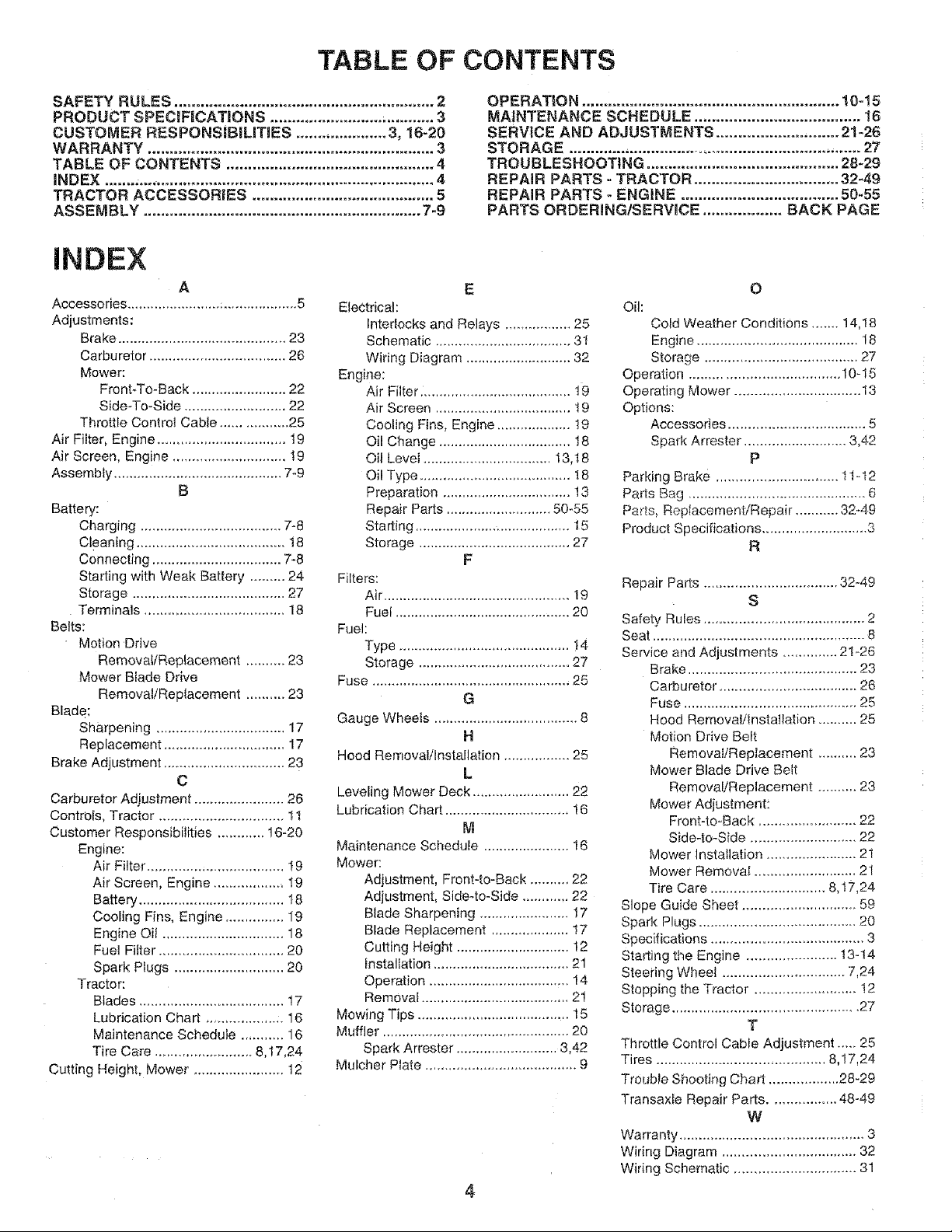
TABLE OF CONTENTS
SAFETY RULES ............................................................ 2
PRODUCT SPECIFICAT|ONS ...................................... 3
CUSTOMER RESPONSiBiUTIES ..................... 3, 16-20
WARRANTY .................................................................. 3
TABLE OF CONTENTS ................................................ 4
iNDEX ............................................................................ 4
TRACTOR AGCESSOR}ES .......................................... 5
ASSEMBLY ................................................................ 7-9
INDEX
A
Accessories ........................ ;................... 5
Adjustments:
Brake ........................................... 23
Carburetor ................................... 26
Mower:
Front_To-Back ........................ 22
Side*To-Side .......................... 22
Throttle Control Cabte ................. 25
Air Filter, Engine ................................. t9
Air Screen, Engine ............................. t9
Assembly ........................................... 7-9
B
Battery:
Charging .................................... 7-8
Cteaning ...................................... 18
Connecting ................................. 7-8
Starting with Weak Battery ......... 24
Storage ....................................... 27
Terminals .................................... 18
Belts:
Motion Drive
Removal/Replacement .......... 23
Mower Blade Drive
Removal/Replacement .......... 23
Blade:
Sharpening ................................. 17
Replacement ............................... 17
Brake Adjustment ............................... 23
C
Carburetor Adjustment ....................... 26
Controls, Tractor ................................ t 1
Customer Responsibilities ............ t 6-20
Engine:
Air Filter ................................... 19
Air Screen, Engine .................. !9
Battery ..................................... 18
Cooling Fins, Engine ............... 19
Engine Oil ............................... 18
Fuel Filter ................................ 20
Spark Plugs ............................ 20
Tractor:
Blades ..................................... ! 7
Lubrication Chart .................... 16
Maintenance Schedule ........... 16
Tire Care ......................... 8,17,24
Cutting Height, Mower ....................... t2
EleCtrical:
Interlocks and Relays ................ 25
Schematic ................................... 3t
Wiring Diagram ........................... 32
Engine:
Air Filter: ...................................... t9
Air Screen ................................... t 9
Cooling Fins, Engine ................... !9
Oil Change .................................. t8
Oil Leve_ ................................. 13,18
Oil Type ....................................... 18
Preparation ................................. 13
Repair Parts ........................... 50-55
Starting ........................................ t5
Storage ....................................... 27
Filters:
Air ................................................ 19
Fuel ............................................. 20
Fuel:
Type ............................................ t4
Storage ....................................... 27
Fuse ................................................... 25
Gauge Wheels ..................................... 8
Hood Removal/Installation ................. 25
Leveling Mower Deck ......................... 22
Lubrication Chart ................................ 16
Maintenance Schedule ...................... 16
Mower:
Adjustment, Front-to-Back .......... 22
Adjustment, Side-to-Side ............ 22
Blade Sharpening ....................... 17
Blade Replacement .................... 17
Cutting Height ............................. 12
Installation ................................... 21
Operation .................................... 14
Removai ...................................... 2!
Mowing Tips ....................................... 15
Muffler ................................................ 20
Spark Attester .......................... 3,42
Mulcher Plate ....................................... 9
OPERATION ........................................................... 10-15
MAINTENANCE SCHEDULE ...................................... 16
SERVICE AND ADJUSTMENTS ............................ 21-26
STORAGE .................................................................... 27
TROUBLESHOOTING ............................................ 28-29
REPAIR PARTS -TRACTOR ................................. 32-49
REPAIR PARTS - ENGINE .................................... 50-55
PARTS ORDERING/SERVmCE .................. BACK PAGE
E
Oi!:
Cold Weather Conditions ....... 14,18
Engine ......................................... 18
Storage ....................................... 27
Ope ration ...................................... 10-15
Operating Mower ................................ 13
Options:
Accessories ................................... 5
Spark Arrester .......................... 3,42
Parking Brake ............................... 11-t2
Pails Bag .............................................. 6
Paris, RepIacementiRepair ........... 32-.4.g
Product Specifications ........................... 3
F
Repair Parts .................................. 32-49
Safety Rules ......................................... 2
Seat ...................................................... 8
Service and Adjustments .............. 2!_26
Brake ........................................... 23
G
H
L
M
Carburetor ................................... 26
Fuse ............................................ 25
Hood Removal/Installation .......... 25
Motion Drive Belt
Removal/Replacement .......... 23
Mower Blade Drive Belt
Removal/Replacement .......... 23
Mower Adjustment:
Front-to-Back ......................... 22
Side-to-Side ........................... 22
Mower lnstaIlation ....................... 21
Mower Removal .......................... 21
Tire Care ............................. 8,17,24
Slope Guide Sheet ............................. 59
Spar]< Plugs ....................................... 20
Specifications ....................................... 3
Starting the Engine ....................... 13-14
Steering Wheel ............................... 7,24
Stopping the Tractor. ......................... t2
Storage ............................................... 27
Throttle Control Cable Adjustment ..... 25
Tires ........................................... 8,17,24
Trouble Shooting Chart .................. 28-29
Transaxle Repair Parts ................. 48-49
Warranty ............................................... 3
Wiring Diagram .................................. 32
Wiring Schematic ............................... 31
O
P
R
S
T
W
4
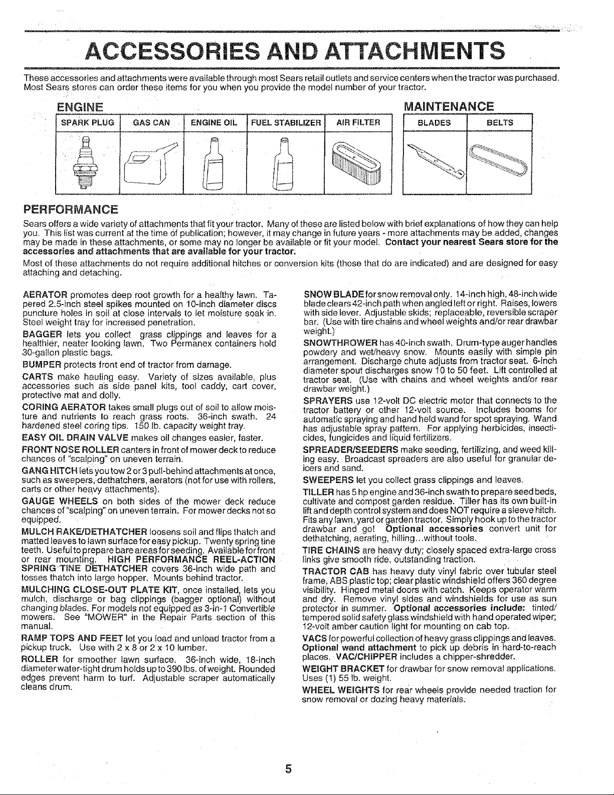
ACCESSORIES AND ATTACHMENTS
These accessories and attachments were available through most Sears retail outlets and service centers when the tractor was purchased.
Most Sears stores can order these items for you when you provide the model number of your tractor.
ENGINE
SPARK PLUG
GAS CAN AIR FILTER BLADES BELTSENGINE OIL
i FUEL STABILIZER
MAINTENANCE
PERFORMANCE
Sears offers a wide vadety ofattachments that fit your tractor. Many of those are listed below with brief explanations of how they can help
you. This list was current at the time Of publication; however, it may change infuture years - more attachments may be added, changes
may be made in these attachments, or some may no longer be available or fit your model. Contact your nearest Sears store for the
accessories and attachments that are available for your tractor.
Most of those attachments do not require additional hltches or conversion kits (those that do are indicated) and are designed for easy
attaching and detaching.
AERATOR promotes deep root growth for a healthy lawn. Ta-
pered 2.5-inch steel spikes mounted on 10-inch diameter discs
puncture holes in soif at close intervals to let moisture soak in.
Steel weight tray for increased penetration.
BAGGER !ets you collect grass clippings and leaves for a
hea{thier, nearer looking lawn. Two Permanex containers hold
30-gallon plastic bags.
BUMPER protects front end of tractor from damage.
CARTS make haufing easy= Variety of sizes available, plus
accessories such aS side panel kits, tool caddy, cart cover,
protective mat and dolly.
CORING AERATOR takes small plugs out of soil to allow mois-
ture and nutrients to reach grass roots. 36-inch swath. 24
hardened steel coring tips. 150 lb. capacity weight tray.
EASY OIL DRAIN VALVE makes oil changes easier, faster.
FRONT NOSE ROLLER canters in front of mower deck to reduce
chances of "scal_ing" on uneven terrain.
GANG HITCH lets you tow 2 or3 pt_tt-behind attachments atonce,
such as sweepers; dethatchers, aerators (not for use with to{lets,
carts or other heavy attachments).
GAUGE WHEELS on both sides of the mower deck reduce
chances of "scalping" on uneven terrain. For mower decks not so
equipped.
MULCH RAKF_./DETHATCHER loosens solt and flips thatch and
matted Ieaves to lawn surface for easy pickup. Twenty spring tine
teeth. Usefulto prepare bare areas for seeding. Available for front
or rear mounting. HiGH PERFORMANCE REEL-ACTiON
SPRING'TtNE DETHATCHER covers 36-inch wide path and
tosses thatch into large hopper. Mounts behind tractor.
MULCHING CLOSE-OUT PLATE KiT, once installed_ !ets you
mulch, discharge or bag clippings (bagger optional) without
changing blades. For models not equipped as 3-in-1 Converfible
mowers. See "MOWER" in the Repair Parts section of this
manual,
RAMP TOPS AND FEET let you load and unload tractor from a
pickup truck. Use with 2 x 8 or 2 x 10 lumber.
ROLLER for smoother lawn surface, 36-inch wide, 18-inch
diameter water-tight drum holds up to 390 lbs. of weight. Rounded
edges prevent harm to turf. Adjustable scraper automatically
cleans drum.
SNOW BLADE for snow removal only. 14-inch high, 48-inch wide
blade dears 42-inch path when angled left or right. Raises, lowers
with side lever. Adjustable skids; replaceable, reversible scraper
bar, (Use with tire chains and wheel weights and/or rear drawbar
weight.)
SNOWTHROWER has 40-inch swath. Drum4ype auger handles
powdery and wet/heavy snow. Mounts easily with simple pin
arrangement. Discharge chute adjusts from tractor seat. 6-inch
diameter spout discharges snow ! 0 to 50 feet. Lift controlled at
tractor seat. (Use with chains and wheel weights and/or rear
drawbar weight.)
SPRAYERS use 12-volt DC electric motor that connects to the
tractor battery or other 12-volt source, includes booms for
automatic spraying and hand held wand for spot spraying. Wand
has adjustable spray pattern. For applying herbicides, insecti-
cides, fungicides and ti_quidfertilizers.
SPREADER/SEEDERS make seeding, fertilizing, and weed kill-
ing easy. Broadcast spreaders are also useful for granular de-
icers and sand.
SWEEPERS let you collect grass clippings and leaves.
TILLER has 5 hp engine and 36-inch swath to prepare seed beds,
cultivate and compost garden residue. Tiiler has its own built-in
lift and depth cont rol system and does NOT require a sleeve hitch.
Fits any lawn, yard or garden tractor. Simp{y hook up to the tractor
drawbar and go! Optional accessories convert unit for
dethatching, aerating, hiliing...without tools.
TIRE CHAINS are heavy duty; closely spaced extra-large cross
links give smooth ride, outstanding traction.
TRACTOR CAB has heavy duty vinyl fabric over tubular steel
frame, ABS ptastic top; clear plastic windshield offers 360 degree
visibility. Hinged metal doors with catch. Keeps operator warm
and dry. Remove vinyl sides and windshields for use as sun
protector in summer. Optional accessories include: tinted/
tempered solid safety glass windshield with hand operated wiper;
12-vott amber caution light for mounting on cab top.
VACS for powerful collection of heavy grass clippings and leaves.
Optional wand attachment to pick up debris in hard-to-reach
places+ VAC/CHiPPER includes a chipper-shredder.
WEIGHT BRACKET for drawbar for snow removal applications.
Uses (t) 55 lb. weight.
WHEEL WEIGHTS for rear wheels provide needed traction for
snow removal or dozing heaw materials.

CO NTS OF HA E PACK
Parts Bag contents shown full size
(1) Hex Bolt 5/16-t8 x I-1/4
(1) Hex Bof
1/2-13 x 1
(1) Lock
(1) Locknut
washer 3/8
5/!6-18
Parts packed separately in carton
Seat
Steering
Wheel
Mulcher
Plate
video
_ _ Cassette
1
(1) Washer 17/32 x (1) Lock
1-3/16 x 12 Gauge Washer 1/2
(2) Washers | i i
3/16 x 3!4 x16 Gauge _ 1
(2) Weld Nuts #10
Steering '
Manual Boot ......
Parts Bag
Parts bag contents not shown full size
(2) Washers 3/8
x 7/8 x 14 Gauge
(2) Shoulder
Bolts
_ Gauge
Steering C
= Extension (2) Keys
Shaft
o
Wheels
Steering Wheel
Adapter
Q(2) Center-
lock Nuts
Steering
Wheel
Insert
(2) Hex Bolts 1/4-20 x 3/4
9/32 x 5/8 x 16 Gauge
(2) Washers
(2) Lock Washers 1/4
(2) Hex Nuts 1/4_20
(2) Latch Hook
Assemblys
Slope Sheet
!6
ASSE _iv.
,_ ................ ,.L.......................
Your new tractor has been assembled at the factory with exception of those parts left unassembled for shipping purposes.
To ensure safe and proper operation of your tractor all parts and: hardware you assemble must be tightened securely, Use
the correct tools as necessary to insure proper tightness.
TOOLS REQUIRED FOR ASSEMBLY
A socket wrench set will make assembly easier. Standard
wrench sizes are listed.
(2) 7/16" wrenches Phitlips Screwdriver
(1) 1/2" wrench Tire pressure gauge
(1) 9/16" wrench Utitity knife
(1) 3/4" Socket w/drive rachet
When right or left hand is mentioned in this manuat, it
means when you are in the operating position (seated
behind the steering wheel).
TO REMOVE TRACTOR FROM CARTON
UNPACK CARTON
Remove all accessible loose parts and parts cartons
from carton (See page 6);
• Cut, from top to bottom, along lines on all four corners
of carton, and lay panets flat,
Check for any additional loose parts or cartons and
remove.
BEFORE ROLLING TRACTOR OFF SKID
WHEEL ............ J....
ADAPTER --_ EXTENSION SHAFT
5/16 HEX BOLT
5116 LOCKNUT
STEERING
BOOT
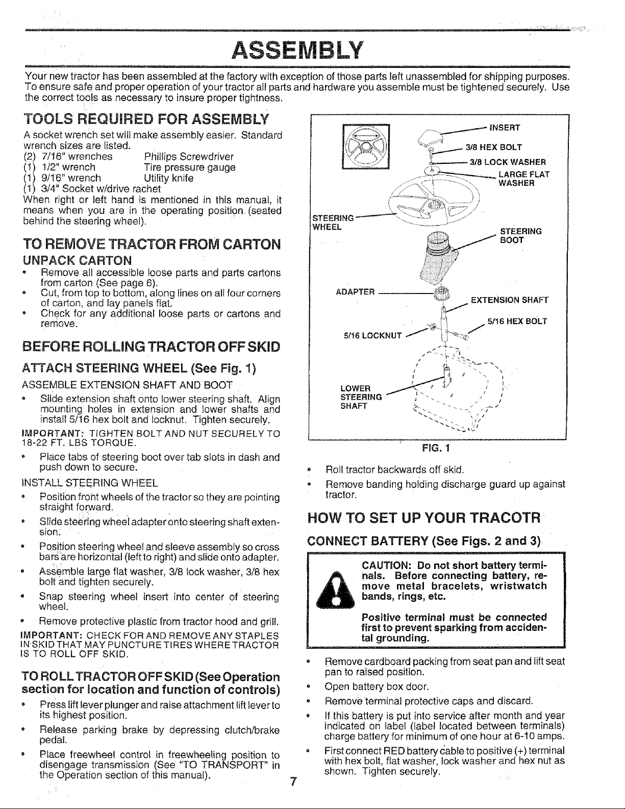
ATTACH STEERING WHEEL (See Fig. I)
ASSEMBLE EXTENSION SHAFT AND BOOT
, Slide extension shaft onto lower steering shaft. Align
mounting holes in extension and lower shafts and
install 5/16 hex bolt and locknut. Tighten securely.
IMPORTANT: TIGHTEN BOLT AND NUT SECURELY TO
18-22 FT. LBS TORQUE.
Place tabs of steering boot over tab slots in dash and
push down to secure.
INSTALL STEERING WHEEL
* Position front wheels of the tractor so they are pointing
straight forward.
o Slide steering wheei adapter onto steering shaft exten-
sion;
o Position steering wheel and sleeve assembly so cross
bars are horizontal (ieftto right) and slide onto adapter.
= Assemble large flat washer, 3/8 lock washer, 3/8 hex
bolt and tighten securely.
= Snap steering wheel insert into center of steering
wheel.
, Remove protective plastic from tractor hood and grill
IMPORTANT: CHECK FOR AND REMOVE ANY STAPLES
IN SKID THAT MAY PUNCTURE TIRES WHERE TRACTOR
IS TO ROLL OFF SKID.
TO RO LL TRACTOR OFF SK|D (See Operation
section for location and function of controls)
, Press liftlever plunger and raise attachment lift lever to
its highest position.
, Release parking brake by depressing clutch/brake
pedal.
o Place freewheel control in freewheeling position to
disengage transmission (See "TO TRANSPORT" in
the Operation Section of this manual).
LOWER _'
STEERING _ . l
SHAFT _ " - __ _ .'_
I
FIG. 1
- Roll tractor backwards off skid.
• Remove banding holding discharge guard up against
tractor.
NOW TO SET UP YOUR TRACOTR
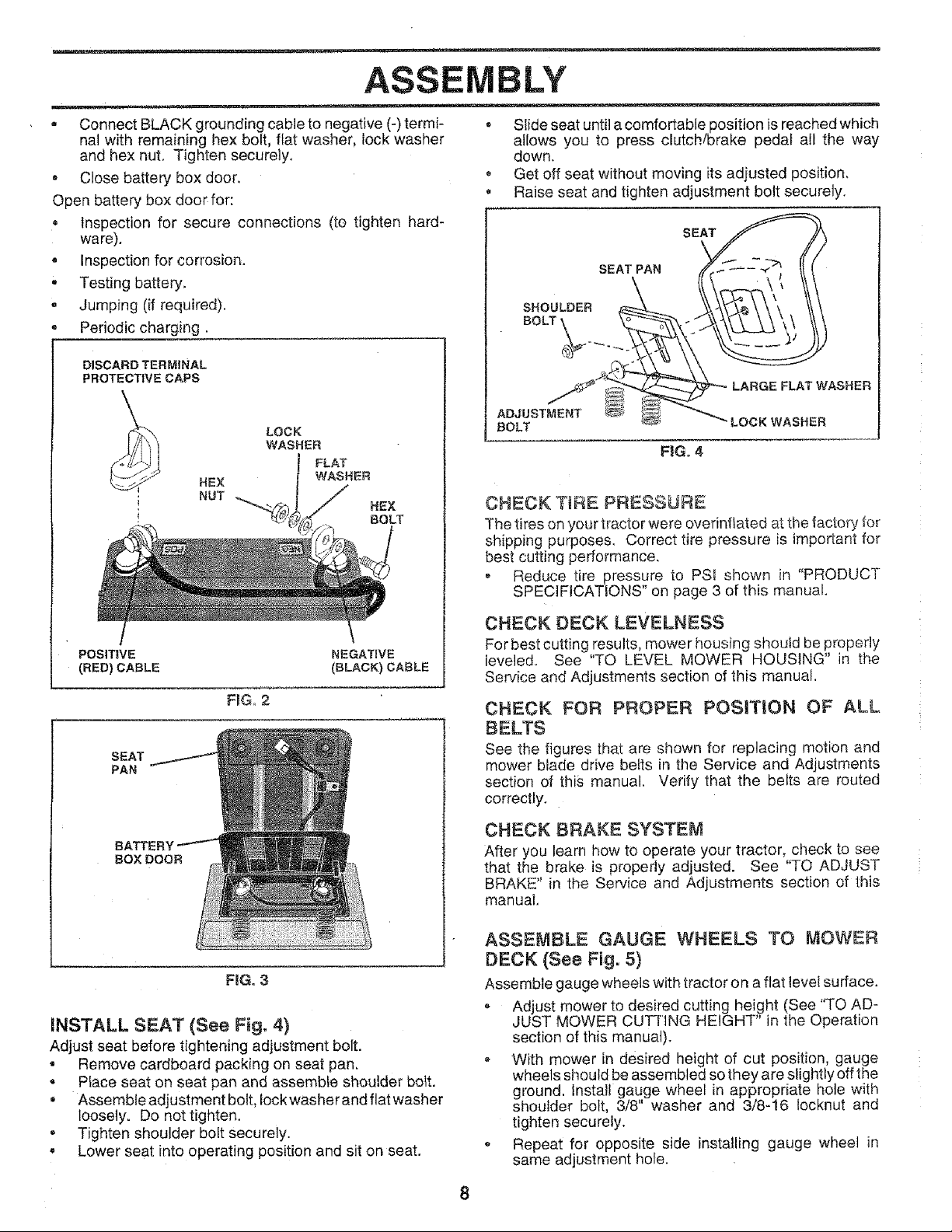
CONNECT BATTERY (See Figs. 2 and 3)
CAUTION: Do not short battery termi-
nals. Before connecting battery, re-
move metal bracelets, wristwatch
bands, rings, etc.
Positive terminal must be connected
first to prevent sparking from acciden-
........ =L= =_
Remove cardboard packing from seat pan and lift seat
pan to raised position.
• Open battery box door.
Remove terminal protective caps and discard.
If this battery is put into service after month and year
indicated on label (label located between terminals)
charge battery for minimum of one hour at 6-10 amps.
, First connect RED battery cabte to positive (+) terminal
with hex bolt, flat washer, lock washer and hex nut as
shown, Tighten securely.
7
tal grounding.
ASSEMBLY
= Connect BLACK grounding cable to negative (-) termi-
nal with remaining hex bolt, fiat washer, lock washer
and hex nut. Tighten securely,
, Close battery box door.
Open battery box door for:
Inspection for secure connections (to tighten hard-
ware).
• Inspection for corrosion.
• Testing battery,
• Jumping (if required).
Periodic charging.
DISCARD TERMINAL
PROTECTIVE CAPS
\
HEX
NUT
HEX
BOLT
, Slide seat until a comfortable position is reached which
allows you to press clutch/brake pedal all the way
down.
• Get off seat without moving its adjusted position,
• Raise seat and tighten adjustment bolt securely.
SEAT
SEAT PAN
SHOULDER
BOLT _
LARGE FLAT WASHER
ADJUSTMENT
BOLT
FiG. 4
"LOCK WASHER
CHECK T_RE PRESSURE
The tires on your tractor were ovefinflated at the factory for
shipping purposes. Correct tire pressure is important for
best cutting performance.
• Reduce tire pressure to PSI shown in "PRODUCT
SPECIFICATIONS" on page 3 of this manual.
I
POSITIVE NEGATWE
(RED) CABLE (BLACK} CABLE
F_G, 2
SEAT
PAN
BATTE
BOX DOOR
FiG. 3
INSTALL SEAT (See Fig, 4)
Adjust seat before tightening adjustment bolt.
• Remove cardboard packing on seat pan.
, Place seat on seat pan and assemble shoulder bolt.
• Assemble adjustment bolt, lock washer and flat washer
loosely. Do not tighten.
, Tighten shoulder bolt securely.
• Lower seat into operating position and sit on seat.
CHECK DECK LEVELNESS
For best cutting results, mower housing should be properly
leveled. See "TO LEVEL MOWER HOUSING" in the
Service and Adjustments section of this manual.
CHECK FOR PROPER POSITION OF ALL
BELTS
See the figures that are shown for replacing motion and
mower blade drive belts in the Service and Adjustments
section of this manual, Verify that the belts are routed
correctly.
CHECK BRAKE SYSTEM
After you learn how to operate your tractor, check to see
that the brake is properly adjusted. See "TO ADJUST
BRAKE" in the Service and Adjustments section of this
manual.
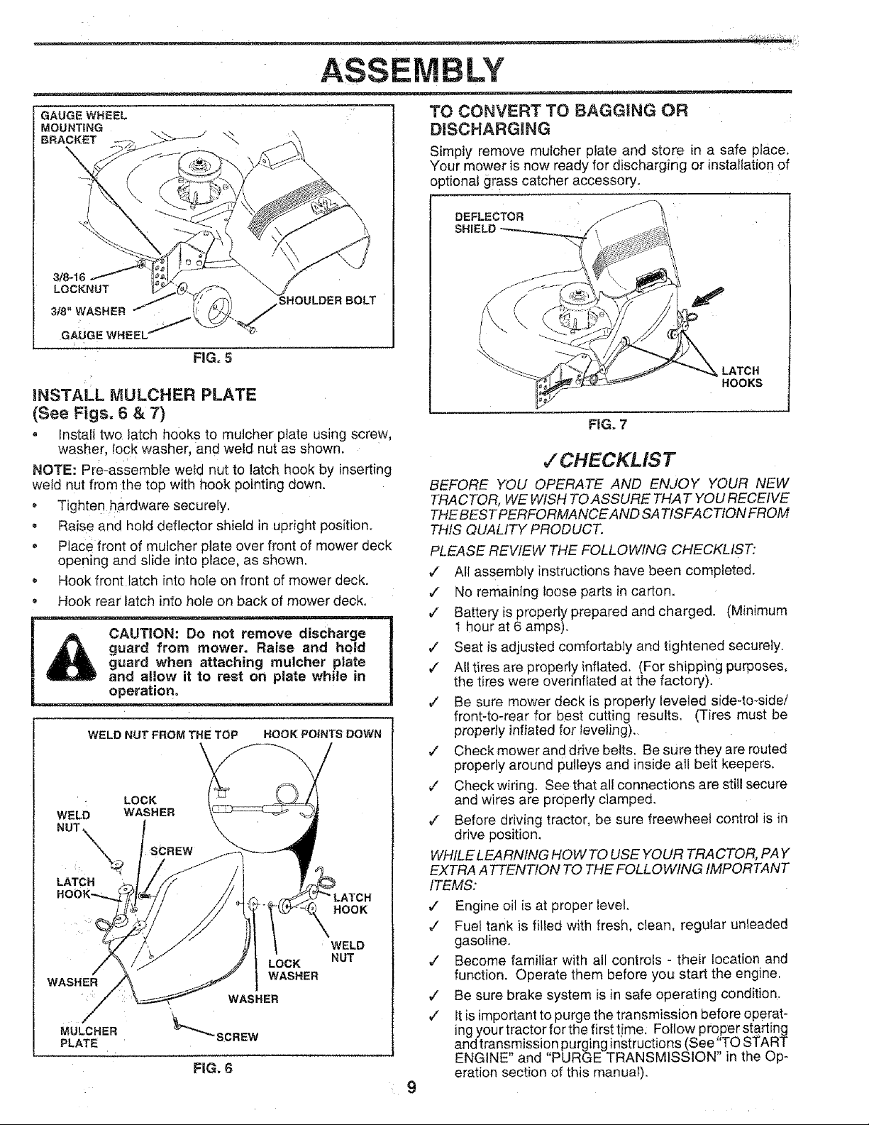
ASSEMBLE GAUGE WHEELS TO MOWER
DECK (See Fig. 5)
Assemble gauge wheels with tractor on a flat level surface.
, Adjust mower to desired cutting height (See "TO AD-
JUST MOWER CUTRNG HEIGHT" in the Operation
section of this manual).
* With mower in desired height of cut position, gauge
wheels should be assembled so they are slightly off the
ground. Install gauge wheel in appropriate hole with
shoulder bolt, 3/8" washer and 3/8-16 Iocknut and
tighten securely.
Repeat for opposite side installing gauge wheel in
same adjustment hole.
°_ i?i
BLY
GAUGE WHEEL
MOUNTING
BRACKET
3/8-16
LOCKNUT
318"WASHER
GAUGE WHEEL"
SHOULDER BOLT
FIG. 5
iNSTALL MULCHER PLATE
(See Figs. 6 & 7)
, Install two latch hooks to mutcher plate using screw,
washer, lock washer, and weld nut as shown.
NOTE: Pro-assemble weld nut to latch hook by inserting
weld nut from the top with hook pointing down.
= Tighten hardware securely.
• Raise and hold deflector shield in upright position.
• Place front of mutcher plate over front of mower deck
opening and slide into place, as shown.
• Hook front latch into hole on front of mower deck.
Hook rear latch into hole on back of mower deck.
CAUTION: Do not remove discharge
guard from mower. Raise and hold
guard when attaching mulcher plate
and allow it to rest on plate while in
operation.
WELD NUT FROM THE TOP HOOK POINTS DOWN
LOCK
WELD WASHER
NUT X SCREW
LATCH
LATCH
HOOK
WELD
NUT
WASHER
MULCHER
PLATE
LOCK
I WASHER
WASHER
FIG, 6
TO CONVERT TO BAGGING OR
DiSCHARGiNG
Simply remove mulcher plate and store in a safe place,
Your mower is now ready for discharging or installationof
optional grass catcher accessory.
DEFLECTOR
LATCH
HOOKS
FiG° 7
,/"CHECKLIST
BEFORE YOU OPERATE AND ENJOY YOUR NEW
TRACTOR, WE WISH TO ASSURE THAT YOU RECEIVE
THE BEST PERFORMANCEAND SATISFACTION FROM
THIS QUALITY PRODUCT.
PLEASE REVIEW THE FOLLOWING CHECKLIST:
,/ All assembly instructions have been completed.
,/ No remaining loose parts in carton.
¢ Battery is properly prepared and charged. (Minimum
1 hour at 6 amps).
¢ Seat is adjusted comfortably and tightened securely.
/ All tires are properly inflated. (For shipping purposes,
the tires were overinfiated at the factory).
¢ Be sure mower deck is properly leveled side-to-side/
front-to-rear for best cutting results. (Tires must be
properly inflated for leveling).
_" Checkmower and drive belts. Be sure they are routed
properly around pulleys and inside all belt keepers.
v" Check wiring. See that all connections are still secure
and wires are properly clamped.
,/ Before driving tractor, be sure freewheel control is in
drive position.
WHILE LEARNING HOW TO USE YOUR TRACTOR, PAY
EXTRA ATTENTION TO THE FOLLOWING IMPORTANT
ITEMS:
¢" Engine oil is at proper level.
¢" Fuel tank is filled with fresh, clean, regular unleaded
gasoline.
,/ Become familiar with all controls - their location and
function. Operate them before you start the engine.
,/ Be sure brake system is in safe operating condition.
¢" It isimportant to purge the transmission before operat-
ing your tractor for the first time: Fo!low proper starting
and transmission purging instructions (See"TO START
ENGINE" and "PURGE TRANSMISSION" in the Op-
eration section of this manual).
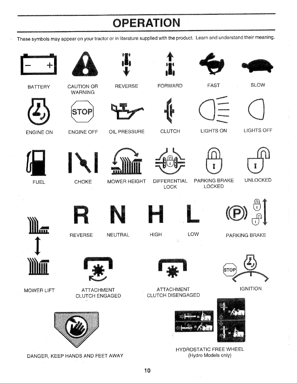
OPERATION
These symbols may appear on your tractor or in literature supp!ied with the product. Learn and understand their meaning.
t
,il
BATTERY
ENGINE ON
CAUTION OR
WARNING
ENGINE OFF
REVERSE
OIL PRESSURE
- IIT
FUEL CHOKE MOWER HEIGHT
FORWARD FAST SLOW
CLUTCH LIGHTS ON LIGHTS OFF
DIFFERENTIAL PARKING BRAKE UNLOCKED
LOCK LOCKED
REVERSE NEUTRAL
MOWER LIFT
DANGER, KEEP HANDS AND FEET AWAY
ATTACHMENT
CLUTCH ENGAGED
HIGH LOW
ATTACHMENT
CLUTCH DISENGAGED
HYDROSTATIC FREE WHEEL
(Hydro Modets only)
10
PARKING BRAKE
IGNITION
OPERATION
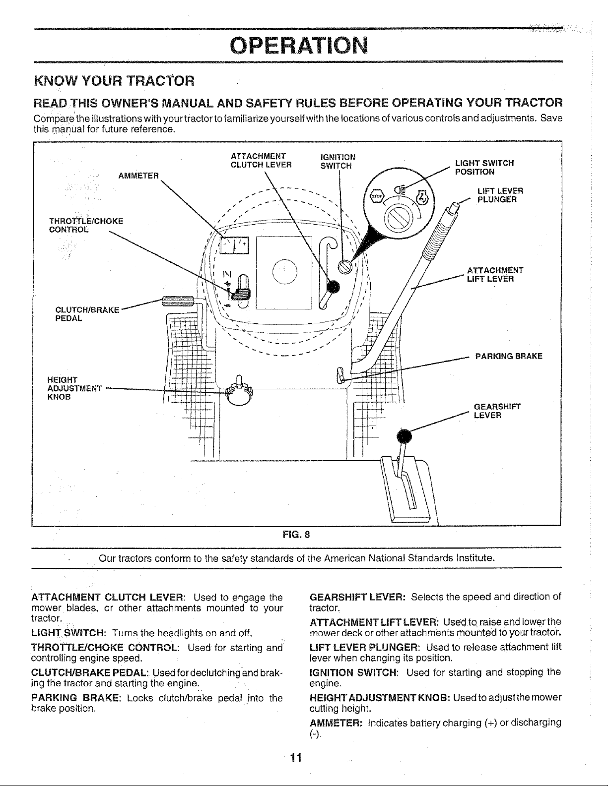
KNOW YOUR TRACTOR
READ,THIS OWNER'S MANUAL AND SAFETY RULES BEFORE OPERATING YOUR TRACTOR
Comparetheiilustrationswithyourtractor tofamiiiarizeyoursetfwiththe{ocations of various controls and adjustments. Save
this manUal for future reference,
CLUTCH/BRAKE
PEDAL
HEIGHT
ADJUSTMENT
KNOB
ATTACHMENT IGNITION
CLUTCH LEVER SWITCH
r
LIGHT SWITCH
POSITION
LiFT LEVER
PLUNGER
ATTACHMENT
LIFT LEVER
PARKING BRAKE
GEARSHIFT
LEVER
• Our tractors conform to the safety standards of the American National Standards institute,
ATTACHMENT CLUTCH LEVER: Used to engage the
mower blades, or other attachments mounted to your
tractor.
LIGHT SWITCH: Turns the headlights on and off.
THROTTLE]CHOKE CONTROL: Used for starting and
controlling engine speed.
CLUTCH/BRAKE PEDAL: Used for declutching and brak-
ing the tractor and starting the engine.
PARKING BRAKE: Locks clutch/brake pedal into the
brake position.
FIG. 8
GEARSHIFT LEVER: Selects the speed and direction of
tractor.
ATTACHMENT LIFT LEVER: Used to raise and lower the
mower deck or other attachments mounted to your tractor,
LiFT LEVER PLUNGER: Used to release attachment lift
lever when changing its position.
IGNITION SWITCH: Used for starting and stopping the
engine.
HEIGHT ADJUSTMENT KNOB" Used to adjust the mower
cutting height,
AMMETER: Indicates battery charging (+) or discharging
(4.
11 •
OPERATION
over the spectacles or standard safety gmasses.
HOW TO USE YOUR TRACTOR o Never use choke to stop engine.
NOTE: Under certain conditions when tractor is standing
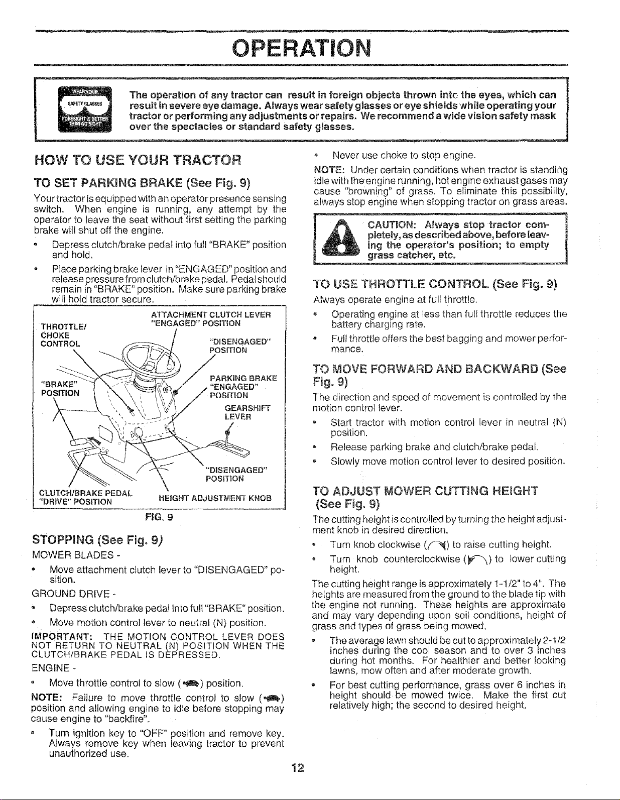
TO SET PARKING BRAKE (See Fig. 9)
Your tractor is equipped with an operator presence sensing
switch. When engine is running, any attempt by the
operator to leave the seat without first setting the parking
brake will shut off the engine.
, Depress clutch/brake pedal into full "BRAKE" position
and hold,
Place parking brake Iever in "ENGAGED" position and
release pressure from clutch/brake pedal. Pedal should
remain in "BRAKE" position. Make sure parking brake
will hold tractor secure,
ATTACHMENTCLUTCHLEVER
THROTTLE/
CHOKE
CONTROL
"ENGAGED"POSITION
idle with the engine running, hot engine exhaust gases may
cause "browning" of grass. To eliminate this possibility,
always stop engine when stopping tractor on grass areas.
pletely, as described above, before leav-
A CAUTION: A_ways stop tractor com-
ing the operator's position; to empty
grass catcher, etc.
TO USE THROTTLE CONTROL (See Fig. 9)
Always operate engine at full throttle,
, Operating engine at less than full throttle reduces the
battery Charging rate.
Futl throttle offers the best bagging and mower perfor-
mance.
GEARSHIFT
LEVER
"D|SENGAGED"
POSI]_ON
CLUTCH/BRAKE PEDAL
"DRIVE" POSITION
HE|GHT ADJUSTMENT KNOB
FIG. 9
STOPPING (See Fig. 9)
MOWER BLADES-
• Move attachment clutch lever to "DISENGAGED" po-
sition,
GROUND DRIVE -
Depress clutch/brake pedal into tuli "BRAKE" position,
Move motion control lever to neutral (N) position,
IMPORTANT: THE MOTION CONTROL LEVER DOES
NOT RETURN TO NEUTRAL (N) POSITION WHEN THE
CLUTCH/BRAKE PEDAL IS DEPRESSED,
ENGINE -
• Move throttle control to slow (,_) position.
NOTE: Failure to move throttle control to slow (,_)
position and allowing engine to idle before stopping may
cause engine to "backfire".
Turn ignition key to "OFF" position and remove key.
Always remove key when ieaving tractor to prevent
unauthorized use.
TO MOVE FORWARD AND BACKWARD (See
Fig. 9)
The direction and speed of movement is controlled by the
motion control lever.
• Start tractor with motion control tever in neutral (N)
position.
, Release parking brake and clutch/brake pedal
= Slowly move motion control fever to desired position.
TO ADJUST MOWER CUTTING HEIGHT
(See Fig. 9)
The cutting height is controlled by turning the height adjust-
ment knob in desired direction.
Turn knob clockwise (f_) to raise cutting height.
Turn knob counterclockwise (_) to lower cutting
height.
The cutting height range is approximately 1-I/2" to 4". The
heights are measured from the ground to the blade tip with
the engine not running, These heights are approximate
and may vary depending upon soif conditions, height of
grass and types of grass being mowed.
, The average lawn should be cutto approximately 2-I/2
inches during the cool season and to over 3 inches
during hot months. For healthier and better looking
lawns, mow often and after moderate growth.
For best cutting performance, grass over 6 inches in
height should be mowed twice. Make the first cut
relatively high; the second to desired height.
!2
• ::;7i!¸:I: !iir_!_i7:7!: ,
OPE AT!ON
t
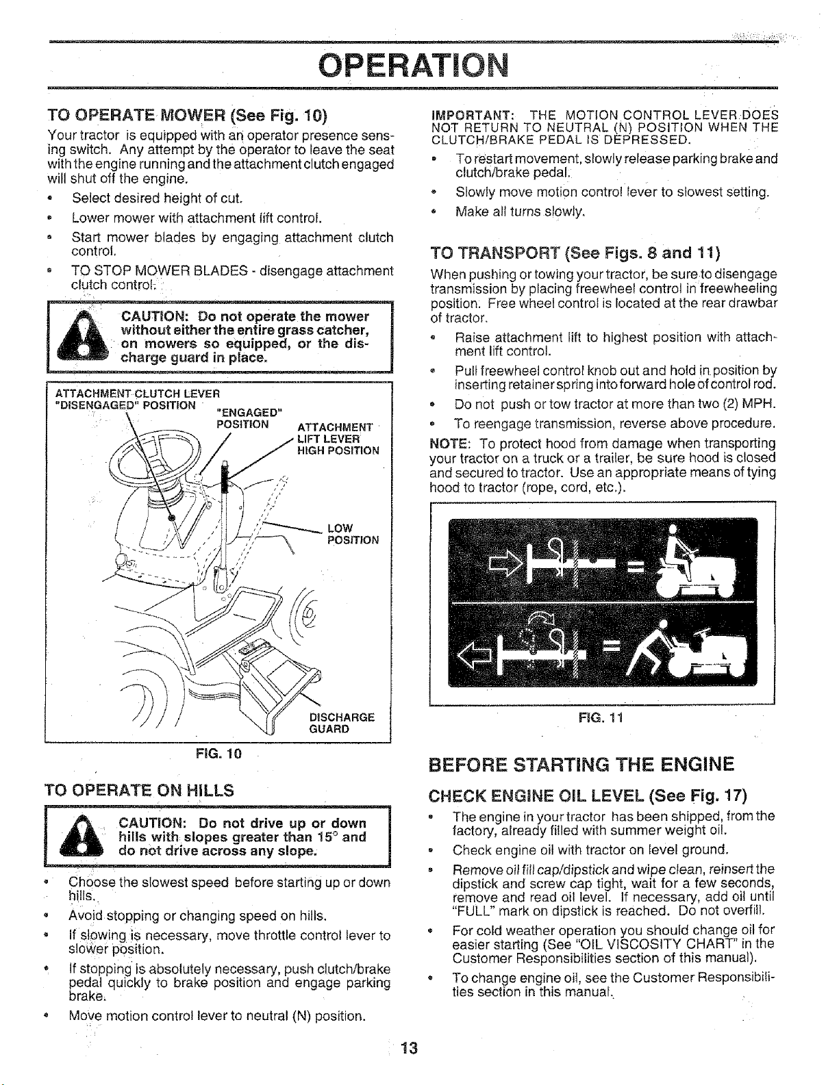
TO OPERATE ,MOWER (See Fig. 10}
Your tractor isequipped Withan operator presence sens-
ing switch. Any attempt by the operator to leave the seat
with the engine running and the attachment clutch engaged
will shut off the engine.
, Select desired height of cut.
, Lower mower with attachment lift control.
, Start mower blades by engaging attachment clutch
control.
. TO STOP MOWER BLADES - disengage attachment
clutch control;:
i _A w_regrasseatcher,
I t_l_ _pad, or the ills-
ATTACHMENT CLUTCH £EVER
"DISENGAGED" POSITION
charge guard in place,
charge guard in place. ................-_
,, \ "ENGAGED"
Y _ _--_._ / i LiFT LEVER
POSITION ATTACHMENT
IMPORTANT: THE MOTION CONTROL LEVER DoEs
NOT RETURN TO NEUTRAL (N) POSITION WHEN THE
CLUTCH/BRAKE PEDAL tS DEPRESSED•
, To restart movement, slowly release parking brake and
clutch/brake pedal;
* Slowly move motion control lever to slowest setting.
- Make all turns slowly.
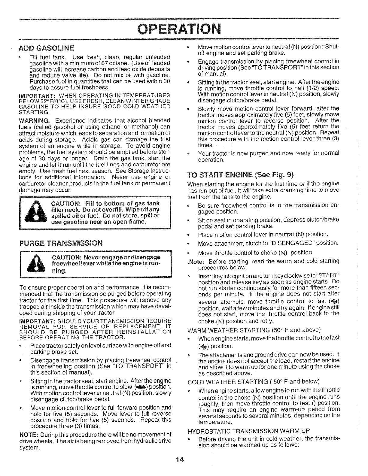
TO TRANSPORT (See Figs. 8 and 11)
When pushing or towing your tractor, be sure to disengage
transmission by placing freewheel control in freewheeling
position: Free wheel control is located at the rear drawbar
of tractor.
o Raise attachment lift to highest position with attach-
merit lift control.
- Pull freewheel control knob out and hold in position by
inserting retainer spring into forward hole of control rod.
, Do not push or tow tractor at more than two (2) MPH.
To reengage transmission, reverse above procedure.
NOTE: To protect hood from damage when transporting
your tractor on a truck or a trailer, be sure hood is closed
and secured to tractor. Use an appropriate means of tying
hood to tractor (rope, cord, etc.).
/ , ,,;::--__._
DISCHARGE
GUARD
FIG. 10
TO OPERATE ON HILLS
CAUTION: Do not drive up or down
! _ hills with:slopes greater than !5 ° and
• ChQose the slowest speed before starting up or down
hills.
• Avo!d stopping or changing speed on hills.
• If slowing iS necessary, move throttle control lever to
sl0wer P6sitiom
, If stopping is absolutely necessary, push clutch/brake
pedal quickly to brake position and engage parking
brake_
Move motion control lever to neutral (N) position.
FIG. 11
BEFORE STARTING TIlE ENGINE
CHECK ENGINE OIL LEVEL (See Fig. 17)
• The engine in your tractor has been shipped, from the
factory, already filled with summer weight oil.
• Check engine oil with tractor on level ground.
, Remove oil fill cap/dipstick and wipe clean, relnsert the
dipstick and screw cap tight, wait for a few seconds,
remove and read oil level. If necessary, add oil until
"FULL" mark on dipstick is reached. Do not overfill.
For cold weather operation you should change oil for
easier start ng (See OIL VISCOSITY CHART n t e
Customer Responsibilities section of this manual).
• To change engine oil, see the Customer Responsibili-
ties section in this manual,
l_ _ • h
i
i
13
OPERATION
ADD GASOMNE
o Fill fuel tank. Use fresh, clean, regular unleaded
gasoline with a minimum of 87 octane. (Use of leaded
gasoline will increase carbon and lead oxide deposits
and reduce valve life). Do not mix oil with gasoline.
Purchase fuel in quantities that can be used within 30
days to assure fuel freshness.
IMPORTANT: WHEN OPERATING IN TEMPERATURES
BELOW 32°F(0°C), USE FRESH, CLEAN WINTER GRADE
GASOLINE TO HELP INSURE GOOD COLD WEATHER
STARTING.
WARNING: Experience indicates that alcohol blended
fuels (called gasohol or using ethanol or methanol) can
attract moisture which leads to separation and formation of
acids during storage. Acidic gas can damage the fuel
system of an engine while in storage. To avoid engine
problems, the fuel system should be emptied before stor-
age of 30 days or longer. Drain the gas tank, start the
engine and let it run until the fuel lines and carburetor are
empty. Use fresh fuel next season. See Storage Instruc-
tions for additional information. Never use engine or
carburetor cleaner products in the fue! tank or permanent
damage may occur.
PURGE TRANSMISSION
To ensure proper operation and performance, it is recom-
mended that the transmission be purged before operating
tractor for the first time. This procedure will remove any
trapped air inside the transmission which may have devel-
oped during shipping of your tractor.
IMPORTANT: SHOULD YOUR TRANSMISSION REQUIRE
REMOVAL FOR SERVICE OR REPLACEMENT, IT
SHOULD BE PURGED AFTER REINSTALLATION
BEFORE OPERATING THE TRACTOR.
o Place tractor safely on level surface with engine off and
parking brake set.
• Disengage transmission by placing freewheel control
in freewheeling position (See "TO TRANSPORT" in
this section of manual).
• Sitting in the tractor seat, start engine. After the engine
is running, move throttle controi to slow (,4_) position.
With motion control lever in neutral (N) position, slowly
disengage clutch/brake pedal,
• Move motion control lever to full forward position and
hold for five (5) seconds. Move lever to full reverse
position and hold for five (5) seconds. Repeat this
procedure three (3) times.
NOTE: During this procedure there will be no movement of
drive wheels. The air is being removed from hydraulic drive
system.
• Move motion control lever to neutral (N) position:-Shut-
off engine and set parking brake.
, Engage transmission by placing freewheel control in
driving position (See "TO TRANSPORT" in this section
of manual)_
• Sitting inthetractor seat, start engine. Aftertheengine
is running, move throttle control to half (1/2) speed.
With motion control lever in neutral (N) position, slowly
disengage clutch/brake pedal.
, Slowly move motion control lever forward, after the
tractor moves approximately five (5) feet, slowly move
motion control lever to reverse position. After the
tractor moves approximately five (5) feet return the
motion control lever to the neutral (N) position. Repeat
this procedure with the motion control lever three (3)
times.
Your tractor is now purged and now ready for normal
operation.
TO START ENGINE (See Fig. 9}
When starting the engine for the first time or-if the engine
has run out of fuel, it will take extra, cranking time to move
fuel from the tank to the engine.
, Be sure freewheel control is in the transmission en-
gaged position.
Sit on seat in operating position, depress clutch/brake
pedal and set parking brake.
, Place motion control lever in neutral (N) position.
Move attachment clutch to "DISENGAGED" position.
o Move throttle control to choke (l\l) position
.Note: Before starting; read the warm and cold starting
procedures below.
• lnsertkeyintoignitionandturnkeyclockwiseto"START"
position and release key as soon as engine starts. Do
not run starter continuously for more than fifteen sec-
onds per minute, tf the engine does not start after
several attempts, move throttle control to fast (,_)
position wait a few minutes and try again. Ifengine still
does not start, move the throttle contro back to the
choke (N) position and retry.
WARM WEATHER STARTING (50° F and above)
- When engine starts, move the throttle control to the fast
(,f_) position.
The attachments and ground drive can now be used. If
the engine does not accept the toad, restart the engine
and allow it to warm up for one minute using the choke
as described above.
COLD WEATHER STARTING ( 50° F and below)
When engine starts, allow engine to run with the throttle
control in the choke (l\i) position until the engine runs
roughly, then move throttle control to fast 0 position.
This may require an engine warm-up period from
several seconds to several minutes, depending on the
temperature.
HYDROSTATIC TRANSMISSION WARM UP
• Before driving the unit in cold weather, the transmis-
sion should be warmed up as follows:
14
OPERATION
............. _ __=-.=
- Place the motion control lever in neutral.
Release the parking brake and let the clutch!brake
s]owty return to operating position.
Allow one minute for transmission to warm uo.
This can be done during the engine warm up
period.
• Theattachments can also be used during the engine
warm_up oeriod after the transmission has been warmed
up.
NOTE: If at a high altitude (above 3000 feet) or in cold
temperatures (below 32 F) the carburetor fuel mixture may
need to be adjusted for best engine performance. See "TO
ADJUST CARBURETOR" in the Service and Adjustments
section of this manual.
MOWING TKPS
Tire chains cannot be used when the mower housing
is attached to tractor.
Mower should be properly leveled for best mowing
performance. See"TQ LEVEL MOWER HOUSING" in
the Service and Adjustments section of this manual.
o The left hand side of mower should be used for trim-
ming.
= Drive so that clippings are discharged onto the area
that has been cut. Have the cut area to the right of the
tractor. This will result in a more even distribution of
clippings and more uniform cutting.
When mowing large areas, start by turning to the right
so that clippings will discharge away from shrubs,
fences, driveways, etc. After one or two rounds, mow
in the opposite direction making Ieft hand turns until
finished (See Fig. 12 ).
If grass is extremely tall, it should be mowed twice to
reduce load and possible fire hazard from dried clip-
pings. Make first cut relatively high; the second to the
desired height.
Do not mow grass when it is wet. Wet grass will plug
mower and leave undesirable clumps, Allow grass to
dry before mowing,
Always operate engine at full throttle when mowing to
assure better mowing performance and proper dis-
charge of material. Regulate ground speed by select-
ing a low enough gear to give the mower cutting
performance as well as the quality of cut desired.
• When Operating attachments, select a ground speed
that wilt suit the terrain and give best performance of
the attachment being used.
f
MULCHmNG MOWING TIPS
mMPORTANT: FOR BEST PERFORMANCE, KEEP
MOWER HOUSING FREE OF BUILT-UP GRASS AND
TRASH. CLEAN AFTER EACH USE,
• The special mulching blade will recut the grass clip-
pings many times and reduce them in size so that as
they fall onto the lawn they will disperse into the grass
and not be noticed. Also, the mulched grass wilt
biodegrade quickly to provide nutrients for the lawn.
Always mulch with your highest engine (blade) speed
as this will provide the best recutting action of the
blades.
• Avoid cutting your tawn when it is wet. Wet grass tends
to form clumps and interferes with the mulching action.
The best time to mow your lawn is the early afternoon.
At this time the grass has dried and the newly cut area
will not be exposed to the direct sun.
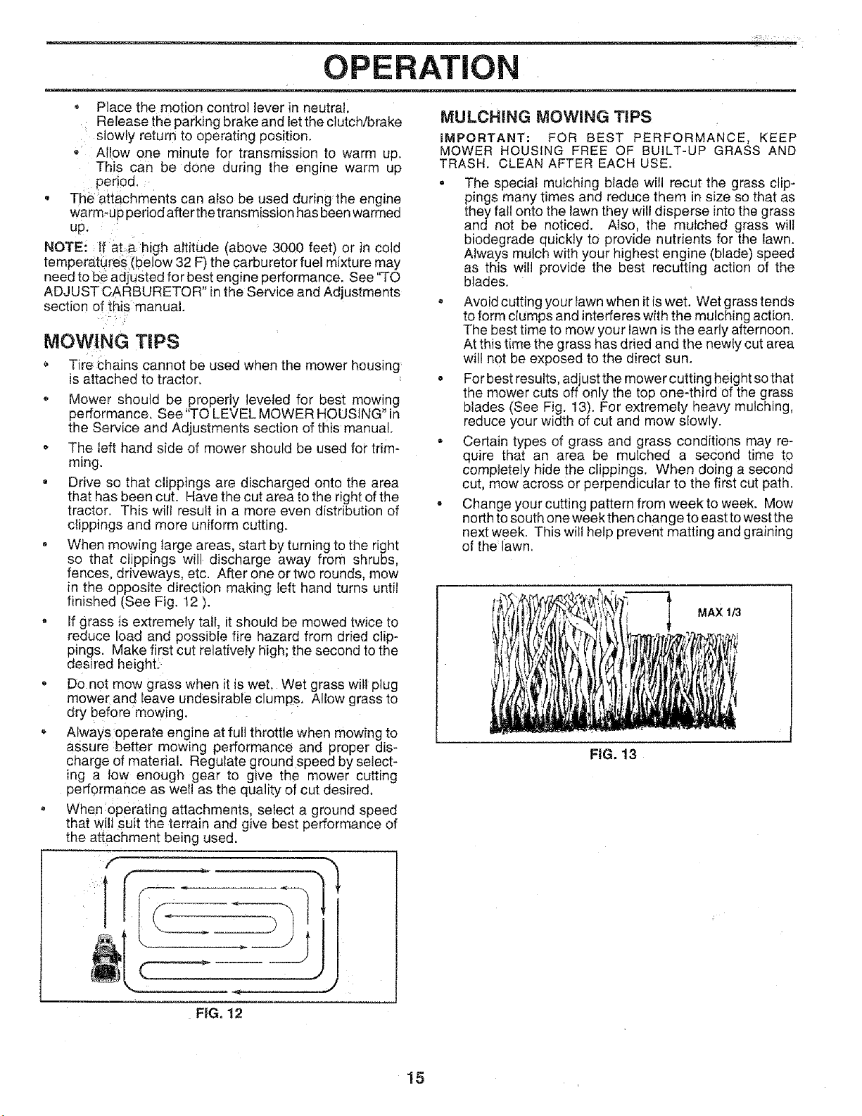
• For best results, adjust the mower cutting height so that
the mower cuts off only the top one,third of the grass
blades (See Fig. 13). For extremely heavy mulching,
reduce your width of cut and mow slowly.
= Certain types of grass and grass conditions may re-
quire that an area be mulched a second time to
completely hide the clippings. When doing a second
cut, mow across or perpendicular to the first cut path.
- Change your cutting pattern from week to week. Mow
north to south one week then change to east to west the
next week. This will help prevent matting and graining
of the lawn.
MAX 1./3
FIG. 13
FIG. 12
15
CUSTOM RESPONSIBILITIES
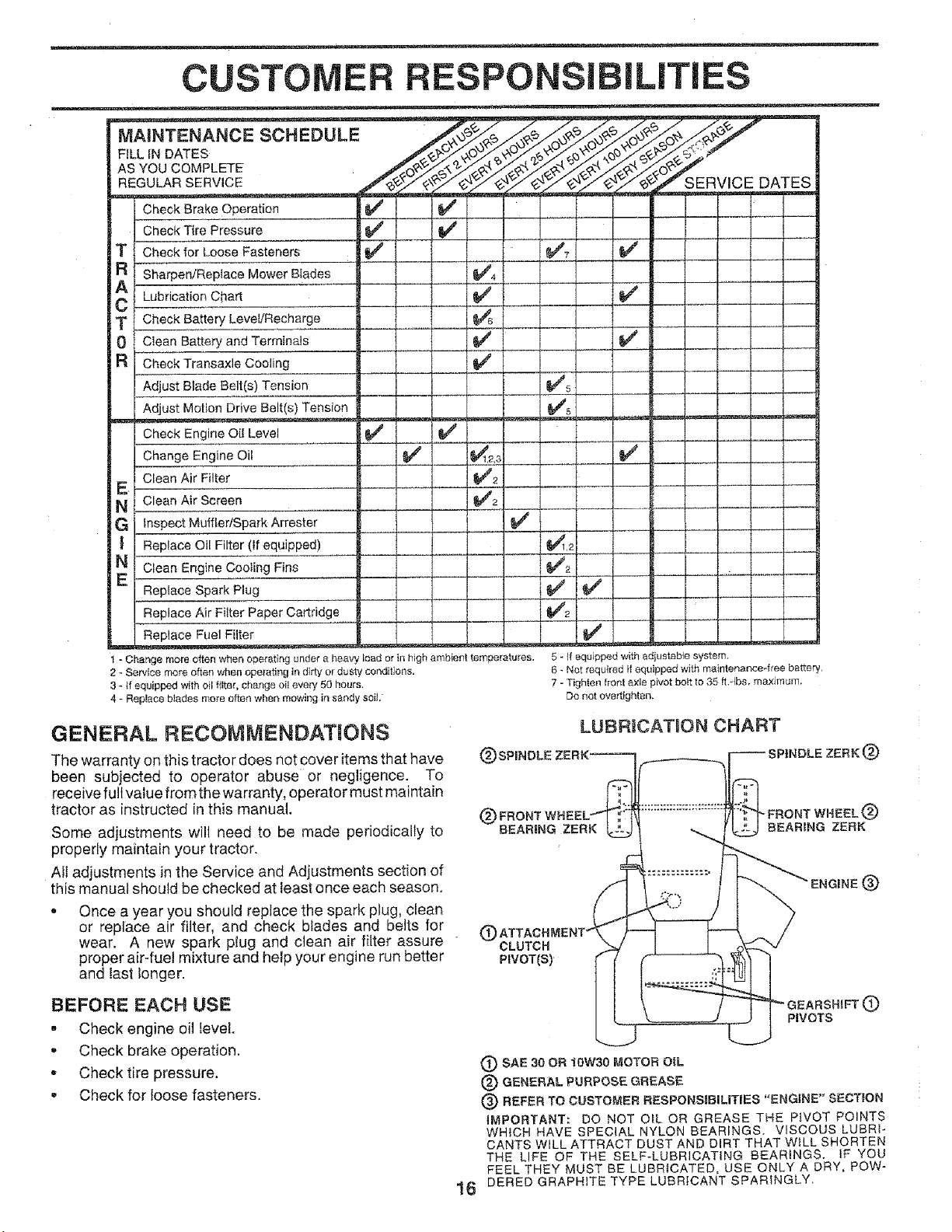
MAINTENANCE SCHEDULE
FILL tN DATES
AS YOU COMPLETE
REGULAR SERVICE
Check Brake Operation
Chec Tire Pressure _ !# #
T I C for Loose Fasteners
a f ,,n/Replace Mower Biades
At ....
C l _tionChart
T l Battery Level/Recharge __
0 t Clean Battery and Terminals
R I Check Transaxle Cooling
Adjust Blade Belt(s) Tension
Adjust Motion Drive Belt(s) Tension
Check Engine Oi[ Level _## _#'
a Engine Oil _ _2,3
_ERVICE DATES
_/7 !J
E 1 Clean Air Filter __ _2 L.
N t Clean f_ir Screen , L_2 ..........
G I InsF t Muffler/Spark Arrester
| I Replace Oil Filter (If equipped) _,2
N t Clean Engine Cooting Fins _f2
E I Re1 ,e Spark Plug _
,oAirF lferPaporCa , dge1 1 I IJ2
-R-eeplaceFuel Filter
1 - Change more often when operating under a heavy _oador in high ambient temperatures.
2 - Service mere often when operating in dirty o[ dusty conditions,
3 - if equipped with oil filter, change oil every 50 hours.
4 - Replace blades more often wl_en mowing in sandy soil,
GENERAL RECOMMENDAT|ONS
The warranty on this tractor does not cover items that have
been subjected to operator abuse or negligence. To
receive full value from the warranty, operator must maintain
tractor as instructed in this manual.
Some adjustments will need to be made periodically to
properly maintain your tractor.
Atl adjustments in the Service and Adjustments section of
this manual should be checked at least once each season.
• Once a year you should replace the spark plug, clean
or replace air filter, and check blades and belts for
wear. A new spark plug and clean air filter assure "
proper air-fuel mixture and help your engine run better
and last longer.
G
(_ FRONT
BEARING ZERK
C)ATTAC
CLUTCH
PIVOT(S)
F
5 _tf equipped with adiustabte system.
6 * Not required if equipped with maintenance*free battery,
7 - Tighten front axle pivot belt to 35 fLqbs, max4mum.
Do not overtighten,
LUBRICATION CHART
NDLE ZERK (_)
FRONT WHEEL
BEARING ZERK
9
BEFORE EACH USE
, Check engine oil level.
o Check brake operation.
• Checktire pressure.
• Check for loose fasteners.
,_EARSHIFT (_
PIVOTS
SAE 30 OR !0W30 MOTOR OIL
(_) GENERAL PURPOSE GREASE
(_) REFER TO CUSTOMER RESPONS_BiLiTIES "ENGINE" SECTION
IMPORTANT: DO NOT OiL OR GREASE THE PIVOT POINTS
WHICH HAVE SPECIAL NYLON BEARINGS, VISCOUS LUBRI-
CANTS WILL ATTRACT DUST AND DIRT THAT WILL SHORTEN
THE LIFE OF THE SELF*LUBRICATiNG BEARINGS, tF YOU
FEEL THEY MUST BE LUBRICATED, USE ONLY A DRY, POW-
DERED GRAPHITE TYPE LUBRICANT SPARINGLY,
16
CUSTOMER RESPONSIBILITIES
TRACTOR
Always observe safety rules when performing any mainte-
nance.
BRAKE OPERATION
ff tractor requires more than six (6) feet stopping distance
at high speed in highest gear, then brake must be adjusted.
(See "TO ADJUST BRAKE" in the Service and Adjust-
ments section of this manuat)i
TIRES
,, Maintain proper air pressure in all tires (See "PROD-
UCT SPECIFICATIONS,' on page 3 of this manual).
• Keep tires free of gasoline, oil, or insect control chemi-
cals which can harm rubber.
, Avoid stumps, stones, deep ruts, sharp objects and
other hazards that may cause tire damage.
NOTE: To seal tire punctures and prevent flat tires due to
slow leaks, tire sealant may be purchased from your local
parts dealer. Tire sealant also prevents tire dry rot and
corrosion.
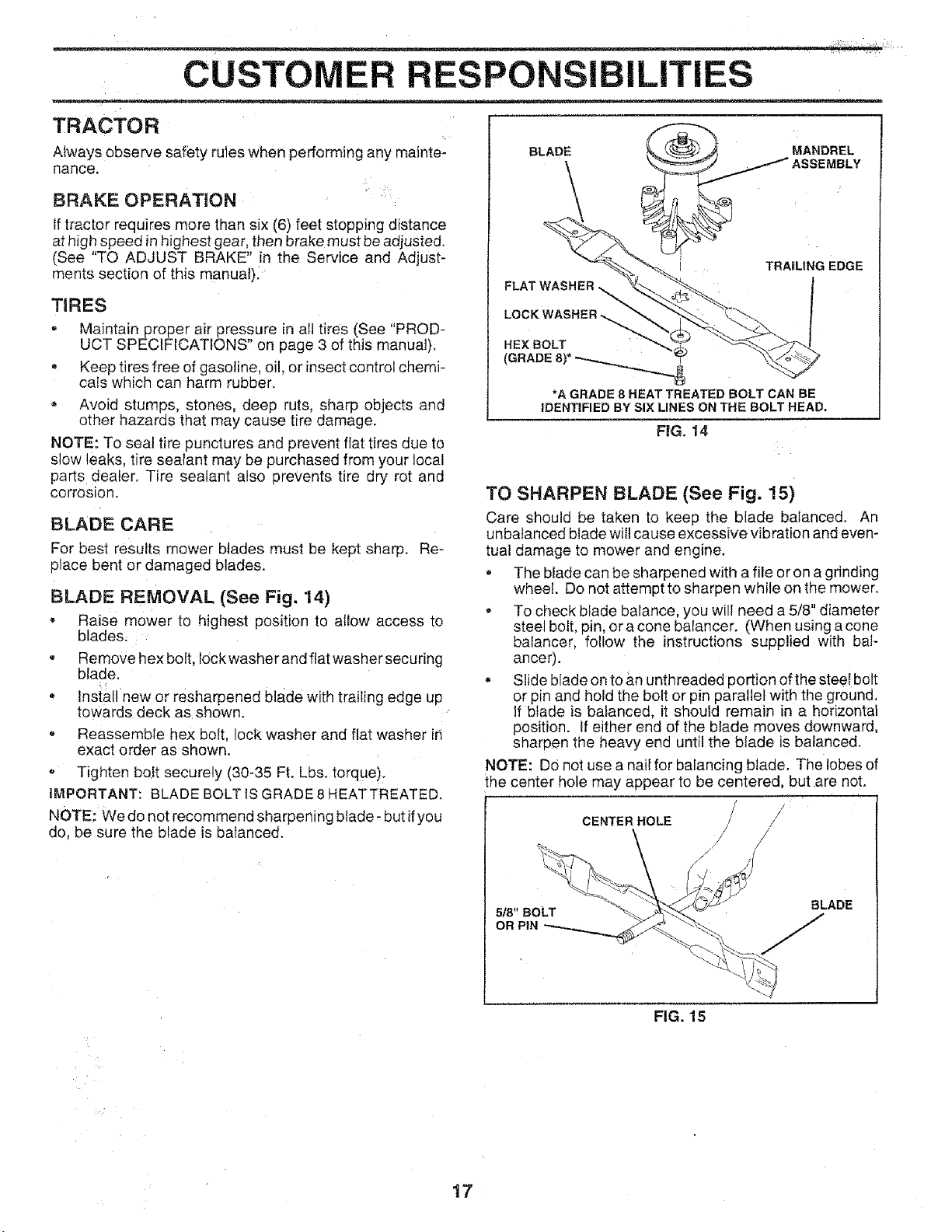
BLADE CARE
For best results mower blades must be kept sharp. Re-
place bent or damaged blades.
BLADE REMOVAL (See Fig. 14)
, Raise mower to highest position to allow access to
blades.
e
Remove hex bolt. lock washer and flat washer securing
blaae.
o
Install new or resharpened blade with trailing edge up
towards deck as shown.
e
Reassemble hex bolt. ocK washer and flat washer ir
exact order as shown.
- Tighten bolt securely (30-35 Ft. Lbs. torque).
IMPORTANT: BLADE BOLT IS GRADE 8 HEAT TREATED.
NOTE: We do natrecommend sharpening btade- but ifyou
do, be sure the blade is balanced.
......................... _!_h?_< ¸
o.,o, c
GE GE
FLAT WASHER _'_-""'_.z
*A GRADE 8 HEAT TREATED BOLT CAN BE
IDENTIFIED BY SIX LINES ON THE BOLT HEAD.
FIG. 14
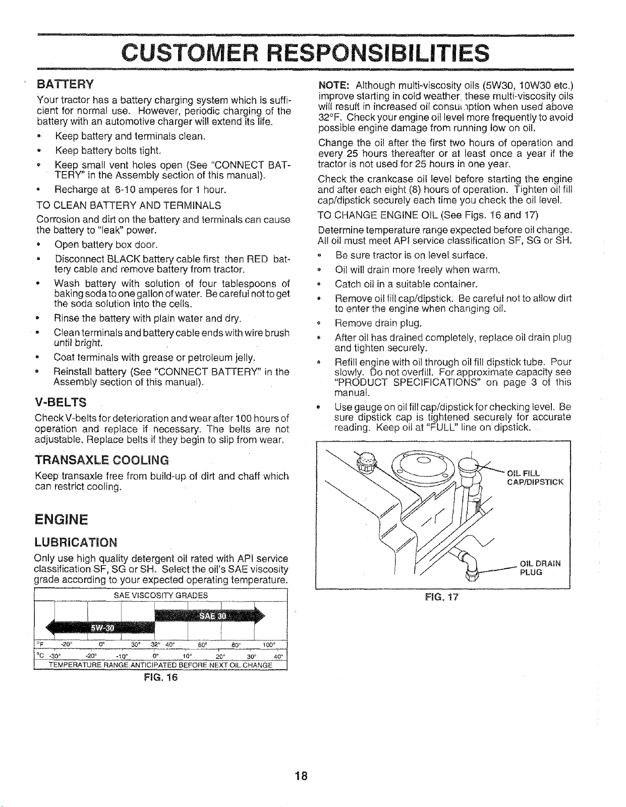
TO SHARPEN BLADE (See Fig. 15)
Care should be taken to keep the blade balanced. An
unbalanced blade will cause excessive vibration and even-
tual damage to mower and engine.
. The blade can be sharpened with a file or on a grinding
wheel. Do not attempt to sharpen while on the mower.
• To check blade balance, you will need a 5/8" diameter
steel belt, pin, or a cone balancer. (When using a cone
balancer, follow the instructions supplied with bai-
anoer).
• Slide blade on to an unthreaded portion of the steel bolt
or pin and hold the bolt or pin parallel with the ground.
If blade is balanced, it should remain in a horizontal
position. If either end of the blade moves downward,
sharpen the heavy end until the blade is balanced.
NOTE: DOnot use a nail for balancing blade. The lobes of
the center hole may appear to be centered, but are not.
CENTER HOLE /
17
5/8" BOLT
OR PIN
BLADE
FIG. 1,5
CUSTO RESPONSIBILITIES
BATTERY
Your tractor has a battery charging system which is suffi-
cient for normal use. However, periodic charging of the
battery with an automotive charger will extend its life.
• Keep battery and terminafs clean.
, Keep battery bolts tight,
- Keep small vent holes open (See "CONNECT BAT-
TERY" in the Assembly section of this manual).
, Recharge at 6-10 amperes for 1 hour.
TO CLEAN BATTERY AND TERMINALS
Corrosion and dirt on the battery and temninals can cause
the battery to "leak" power.
Open battery box door.
= Disconnect BLACK battery cable first then RED bat-
tery cable and remove battery from tractor.
• Wash battery with solution of four tablespoons of
baking soda to one gallon of water. Be careful ndtto get
the soda solution into the cells,
o
Rinse the battery with plain water and dry.
e
Clean terminals and battery cable ends with wire brush
until bright.
, Coat terminals with grease or petroleum jelly.
, Reinstall battery (See "CONNECT BATTERY!' in the
Assembly section of this manual).
V-BELTS
Check V-belts for deterioration and wear after 100 hours of
operation and replace if necessary. The belts are not
adjustable. Replace belts if they begin to slip from wear.
NOTE: Although multi-viscosity oils (5W30, 10W30 etc.)
improve starting in cold weather these multi-viscosity oils
will result in increased oil consu_nption when used above
32°F. Check your engine oil level more frequently to avoid
possible engine damage from running tow on oil.
Change the oii after the first two hours of operation and
every 25 hours thereafter or at least once a year if the
tractor is not used for 25 hours in one year.
Check the crankcase oil level before starting the engine
and after each eight (8) hours of operation. Tighten elf fill
cap/dipstick securely each time you check the oi! level.
TO CHANGE ENGINE OIL (See Figs. 16 and 17)
Determine temperature range expected before oil change.
All oil must meet API service classification SF, SG or SH.
o Be sure tractor is on level sudace.
Qit will drain more freely when warm.
, Catch oil in a suitable container.
Remove oil fill cap/dipstick: Be careful not to allow dirt
to enter the engine when changing oil.
Remove drain plug.
After oil has drained completely, replace oil drain plug
and tighten securely.
Refill engine with oil through oil fill dipstick tube. Pour
slowly. Do not overfill. For approximate capacity see
"PRODUCT SPECIFICATIONS" on page 3 of this
manual.
° Use gauge on oil fill cap/dipstick for checking level. Be
sure dipstick cap is tightened securely for accurate
reading. Keep oit at "FULL" line on dipstick.
TRANSAXLE COOLING
Keep transaxle free from build-up of dirt and chaff which
can restrict cooling.
ENGINE
LUBRiCAT!ON
Only use high quality detergent oil rated with API service
classification SF, SG or SH. Select the oil's SAE viscosity
grade according to your expected operating temperature.
SAE VISCOSITY GRADES
.20 ° 0_ 60 _
_30o _20o .I0o 0_ 10 ° 20 ° 30_ 40 °
TEMPERATURE RANGE ANTICIPATED BEFORE NEXT OIL CHANGE
FIG. 16
FILL
CAP/DIPSTICK
OIL DRA_N
PLUG
FilG. i7
18
 Loading...