

Page 1

CR/ FTX
MODEL NUMBER 917.258530 OWNER'S MANUAL
° Assembly
° Operation
° Customer Responsibilities
° Service and Adjustments
oRepair Parts
CAUTION: Read and follow all safety rules and instructions before operating this equipment.
FOR CONSUMER ASSISTANCE HOT LINE, CALL THiS TOLL FREE NUMBER: 1-800-659-5917
Page 2

Safe Operation Practices for Ride-On Mowers
IMPORTANT: THIS CUTTING MACHINE IS CAPABLE OF AMPUTATING HANDS AND FEET AND THROWING OBJECTS,
FAILURE TO OBSERVE THE FOLLOWING SAFETY INSTRUCTIONS COULD RESULT IN SERIOUS INJURY OR DEATH_
SAFETY RULES
I, GENERAL OPERATION
• Read, understand, and follow all instructionsinthemanual
and on the machine before starting
° Only allow responsible adults, who are familiar with the
instructions,tooperate the machine°
• Clear the area of objects such as rocks, toys, wire, etc.,
whichcould be picked up and thrown by the blade.
° Besurethe area is clear of otherpeoplebefore mowing Stop
machine if anyone enters the area.
• Never carry passengers°
• Do not mow in reverse unless absolutelynecessary Always
look down and behind before and while backing.
• Be aware of the mower discharge direction and do not point
it at anyone. Do not operate the mower withouteither the
entire grass catcher or the guard in place.
• Slow down before turn_ng_
• Never leave a running machine unattended. Always turnoff
blades, set parking brake, stop engine, and remove keys
before dismounting
° Turn off blades when not mowing
° Stop engine before removing grass catcher or unclogging
chute°
• Mow only indaylight or good artificial lighL
• Do not operate the machine while under the influence of
alcohol or drugs°
• Watch for trafficwhen operatingnear or crossingroadways.
° Use extra care when loading or unloading the machine into
a trailer ortruck._
I!. SLOPE OPERATION
Slopes are a major' factor related to loss-of-control and
tipover accidents, which carl result in severe injury or death°
Al! slopes require extra caution. If you cannot back up the
slope or if you feel uneasy on it, do not mow it..
DO:
° Mow up and down slopes, not across.
= Remove obstacles such as rocks, tree limbs, etc.
° Watch .for holes, ruts, or bumps. Uneven terrain could
overturn the machine. Tall grass can hide obstacles.
= Use slow speed. Choose a low gear so thatyou will not have
to stop or shift while on the slope.,
• Follow the manufacturer's recommendations for wheel
weights or counterweights to improve stability,
• Use extra care with grass catchers or other attachments_
These can change the stability of the machine.
• Keep all movement on the slopes slowand gradual. Do not
make sudden changes in speed or direction.
= Avoid starting or stopping on a slope. If tires lose traction,
disengage the blades and proceed slowly straight down the
slope.,
DO NOT;
° Donot turnonslopes unlessnecessary, andthen, turnslowly
and gradually downhill, ifpossible,.
° Do not mow near drop-offs, ditches, or embankments. The
mower could suddenly turn over if a wheel isover the edge
of a cliff or ditch, or if an edge caves in.
• Do not mow on wet grass. Reduced traction could cause
sliding.
• Do not tryto stabilize themachine by puttingyour foo!onthe
ground,
. Do not use grass catcher on steep slopesv
Ill. CHILDREN
Tragic accidents can occur ifthe operator is not alert to the
presence of children° Children are often attracted to the
machine and the mowing activity_ Never assume that
children will remain where you last saw them.
* Keep children out ofthe mowing area and under the watchful
care of another responsible aduEt.
' Be alert and turn machine off if children enter the area.
. Before and when backing, look behind and down for small
children.
* Never carry children. They may fall off and be seriously
injured or interfere with safe machine operation.
o Never allow children to operate the machine.
- Use extra care when approaching blind corners, shrubs,
trees, or other objectsthat may obscure vision.
IV. SERVICE
• Use extra care inhandlinggasoline and otherfuels_ They are
flammable and vapors are explosive,
Use only an approved container,
Never remove gas cap or add fuel with the engine
running. Allow engine to cool before refueling. Do not
smoke..
Never refuel the machine indoors.
- Never store the machine or fuel container inside where
there is an open flame, such as awater heater,.
° Never run a machine inside a closed area.
° Keep nuts and bolts, especially blade attachment bolts, tight
and keep equipment in good condition,.
= Never tamper with safety devices. Check their proper
operatio n regularly,
° Keep machine free of grass, leaves, or other debris build-up_
Clean oil or fuel spillage, Allow machine to cool before
storing.
° Stop and inspect the equipment if you strike an object°
Repair, if necessary, before restarting.
° Never make adjustments or repairs with the engine running_
° Grass catcher components are subject to wear-,damage, and
deterioration, whtch could expose moving parts or allow
objects to be thrown. Frequently check components and
replace with manufacturer's recommended parts, when nec-
essary.
• Mower blades are sharp and can cut. Wrap the blade(s) or
wear gloves, and use extra caution when servicing them.
° Check brake operation frequently. Adjust and service as
required.
i iHlll illll
portant safety precautions. It means
CAUTION!H BECOME ALERTH! YOUR
Look for this symbol to point out im-
SAFETY IS INVOLVED.
.....C'AUTION: Always disconnect spark plug
spark plug in order to prevent accidental
wireand placewirewhere it cannot contact
-,starting when setting up, transporting,
adjusting or making repairs,
ILII
WARNING
The engine exhaust from this product con-
tains ctiemicals known to the State of Califor-
nia to cause cancer, birth defects, or other
reproductive harm.
2
Page 3

CONGRATULATIONS on your purchase of a Sears
Tractor° It has been designed, engineered and manufac-
tured to give you the best possible dependability and
performance.
Should you experience any problem you cannot easily
remedy, please contact your nearest Sears Authorized
Service CentedDepartment. We have competent, well-
trained technicians and the proper tools toservice or repair
this tractor.
Please read and retain this manual° The instructions will
enable you to assemble and maintain your tractor properly_
Always observe the "SAFETY RULES".
MODEL
NUMBER 917°258530
SERIAL
NUMBER
DATE OF PURCHASE
THE MODEL AND SERIAL NUMBERS WILL BE FOUND
ON A PLATE UNDER THE SEAT°
YOU SHOULD RECORD BOTH SERIAL NUMBER AND
DATE OF PURCHASE AND KEEP IN A SAFE PLACE
FOR FUTURE REFERENCE_
PRODUL, SPECIFICATIONS
HORSEPOWER: 15.5
GASOLINE CAPACITY 1.25 GALLONS
AND TYPE: UNLEADED REGULAR
OIL TYPE (API-SF/SG): SAE 30 (above 32°F)
OIL CAPACITY: 3.0 PINTS
SPARK PLUG: CHAMPION RJtgLM
(GAP: °030")
VALVE CLEARANCE: INTAKE: .005" - ..007"
GROUND SPEED (MPH): FORWARD: 0- 5°5
TIRE PRESSURE: FRONT: 14 PSI
CHARGING SYSTEM: 3 AMPS BATTERY
BATTERY: AMP/HR: 25
BLADE BOLT TORQUE: 30-35 FT. LBS.
SAE 5W-30 (below 32°F)
EXHAUST: .009" - _011"
REVERSE: 0- 2.4
REAR: 10 PSi
5 AMPS HEADLIGHTS
MIN. CCA: 190
CASE SIZE: U1R
MAINTENANCE AGREEMENT
A Sears Maintenance Agreement is available on this prod_
uct. Contact your nearest Sears store for details_
CUSTOMER RESPONSIBILITIES
. Read and observe the safety rules,.
• Follow a regular schedule in maintaining, caring for and
using your tractor,
= Follow the instructions under "Customer Responsibili-
ties" and "Storage" sections of this owner's manual°
WARNING: This tractor is equipped with an internal
combustion engine and should not be used on or near any
unimproved forest-covered, brush-covered or grass-cov-
ered land unless the engine's exhaust system is equipped
with a spark arrester meeting applicable local orstate laws
(if any)° Ifa spark arrester is used, it should be maintained
in effective working order by the operator.
In the state of California the above is required by law
(Section 4442 of the Caiifornia Public Resources Code)°
Other states may have similar laws. Federal laws apply on
federal lands. A spark arrester for the muffler is available
through your nearest Sears Authorized Service Center/
Department (See REPAIR PARTS section of this manual)_
LIMITED TwO YEAR WARRAN ON CRAFTSMAN RIDING EQUIPMENT
For two (2) years from the date ofpurchase, if this Craftsman Riding Equipment is maintained, lubricated and tuned up according
to the instructionsin the owner's manual, Sears will repair or replace, free of charge, any parts found to be defective inmaterial or
workmanship.
This Warrant,/does not cover:
• Expendable items which become worn during normal use, such as blades, spark plugs, air cleaners, belts, etc.
• Tire replacement or repair caused by punctures from outside objects, such as nails, thorns, stumps, or glass.
° Repairs necessary because of operator abuse, negligence, improper storage or accident or the failure to maintain the
equipment according to the instructions contained in the owner's manual.
° Riding equipment used for commercial or rental purposes_
LIMITED 90 DAY WARRANTY ON BATTERY
For ninety (90) days from date of purchase, if any battery included with this riding equipment proves defective in material or
workmanshipand ourtesting determines the battery willnot hold a charge, Sears witIreplace the battery at no charge,
1N-HOME WARRANTY SERVICE ON YOUR CRAFTSMAN RIDING EQUIPMENT 1S AVAILABLE AT NO-CHARGE FOR 30
DAYS FROM THE DATE OF PURCHASE,. PLEASE CONTACT YOUR NEAREST SERVICE CENTER° AFTER 30 DAYS FROM
THE DATE OF PURCHASE, WARRANTY' SERVICE IS AVAILABLE BY TAKING YOUR CRAFTSMAN RIDING EQUIPMENT TO
YOUR NEAREST SEARS SERVICE CENTER. (IN-HOME WARRANTY SERVICE WILL STILL BE AVAILABLE AFTER 30 DAYS
FROM THE DATE OF PURCHASE BUT A STANDARD TRIP CHARGE WILL APPLY.) THIS WARRANTY APPLIES ONLY
WHILE THIS PRODUCT IS IN THE UNITED STATES.
This Warranty gives you specific legal rights, and you may also have other rights which may vary from state to state.
SEARS, ROEBUCK AND CO., D/817 WA, HOFFMAN ESTATES, IL 60179
.......................... , H, HHH,HH I IIII I IUl II NNNNII III
3
Page 4

TABLE OF CONTENTS
SAFETY RULES ............................................................ 2
PRODUCT SPECIFICATIONS ....................................... 3
CUSTOMER RESPONSIBILITIES ..................... 3, 16-20
WARRANTY .................................................................. 3
TABLE OF CONTENTS ................................................ 4
INDEX ............................................................................ 4
TRACTOR ACCESSORIES .......................................... 5
ASSEMBLY ................................................................ 7-9
INDEX
A
Accessories .....................................................5
Adjustments:
Brake .........................................................23
Carburetor ..........................................26
Mower:
Front-To-Back ................................22
Side-To-Side ....................................22
Throttle Control Cable ........................25
Air Filter, Engine ................................................19
Air Screen, Engine ........................................19
Assembly ............................................................7-9
B
Battery:
Charging ......................................................7-8
Cleaning .................................................18
Connecting ........................................7-8
Starting with Weak Battery .............24
Storage .............................................27
Tem]inats ................................................18
Belts:
Motion Drive
Removal/Replacement ..............23
Mower Blade Drive
Removal/Replacement .......... 23
Blade:
Sharpening ............................................17
Replacement ......................................17
Brake Adjustment .....................................23
C
Carburetor Adjustment ..........................26
Controls, Tractor. ...................................11
Customer Responsibilities ............. 16-20
Engine:
Air Filter..........................................19
Air Screen, Engine ......................19
Battery ...........................................................18
Cooling Fins, Engine ..................!9
Engine Oil .......................................18
Fuel Fiiter. ...........................................20
Spark Plugs ..................................20
Tractor:.
Blades ....................................................t7
LubricationChart ..........................i6
Maintenance Schedule ...................t 6
Tire Care ..................................8,t7,24
Cutting Height, Mower ..................................12
Electrical:
Interlocks and ReEays.......................25
Schematic .........................................31
Wiring Diagram ...................................32
Engine:
Air Filter,................................._........................19
Air Screen .........................................19
Cooling Fins, Engine ............................19
Oil Change ........................................18
Oil Level .........................................13,18
Oil Type .............................................18
Preparation ...........................................13
Repair Parts ............................................50-55
Starting .......................................................15
Storage ......................................................27
Filters:
Air..................................................................19
Fuel .............................................................20
Fuel:
Type ....................................................14
Storage ................................................27
Fuse .................................................................25
Gauge Wheels ....................................................8
Hood Removal/Installation .......................25
Leveling Mower Deck .................................22
LubricationChart ................................. 16
Maintenance Schedule ..............................16
Mower:
Adjustment, Front-to-Back ...............22
Adjustment, Side-to-Side ...............22
Blade Sharpening ..............................17
Blade Replacement ...................................17
Cutting Height ...........................................12
Installation................................................21
Operation ..........................................t4
Removal .............................................21
Mowing Tips ...............................................15
Muffler ...................................................:20
Spark Arraster .................................3,42
Mulcher Plate ........................................................9
OPERATION ........................................................... 10-15
MAINTENANCE SCHEDULE ...................................... 16
SERVICE AND ADJUSTMENTS ............................ 2%26
STORAGE ................................................................... 27
TROUBLESHOOTING ............................................ 28-29
REPAIR PARTS - TRACTOR ................................. 32-49
REPAIR PARTS - ENGINE .................................... 50-55
PARTS ORDERING/SERVICE .................. BACK PAGE
E
Oil:
Cold Weather Conditions .........14,18
Engine ...........................................................18
Storage ................................................27
Operation ................................................10-15
Operating Mower ...............................................13
Options:
Accessories .............................. .......... 5
Spark Arrester _...............................3,42
O
P
Parking Brake ........................................11-12
Parts Bag ......................................................6
Parts, Replacement/Repair ...............32-49
Product Specifications ....................................3
R
F
Repair Parts ..............................................32-49
S
Safety Rules ..............................................2
Seat ..................................................................8
Service and Adjuslments .................21-26
Brake ............................. ......................... 23
G
H
L
M
Carburetor _............................................26
Fuse ....................................................................25
Hood Removal/Installation ............25
Motion Drive Belt
RemovaUReplacement ..............23
Mower Blade Drive Belt
Removal/Replacement .......... 23
Mower Adjustment:
Front-to-Back ...............................22
Side-to-Side...........................................22
Mower Installation ............................... 21
Mower Removal ...................................21
Tire Care ...................................8,17,24
Slope Guide Sheet ................................59
Spark Plugs ..............................................20
Specifications .................................... ................. 3
Starting the Engine ................................... 13-14
Steering Wheel ............................................. 7,24
Stopping the Tractor ......................................12
Storage................................................................27
r
Throttle Control Cable Adjustment ..... 25
Tires ...........................................................8,17,24
Trouble Shooting Chart ........................28-29
Transaxle Repair Parts.....................48-49
W
Warranty ..............................................................3
WiringDiagram ..........................................32
Wiring Schematic ............................................31
4
Page 5

ACCESSORIES AND ATTACHMENTS
These accessories and attachments were available through most Sears retail outlets and service centers when the tractor was purchased,
Most Sears stores can order these items for you when you provide the model number of your tractor,
ENGINE MAINTENANCE
SPARK PLUG BLADESGASCAN ENGINEOIL
FUELSTABILIZER
AIRFILTER
BELTS
%
PERFORMANCE
Sears offers a wide variety of attachmentsthatfityourtractor_ Many ofthese are listed belowwith briefexplanationsof howthey can help
you° This listwas current at the time ofpublication;however, it may change infuture years - more attachments may be added, changes
may be made in these attachments, or some may no longer be available or fit your model Contact your nearest Sears store for the
accessories and attachments that are available for your tractor,
Most of these attachments do not require additional hitchesor conversionkits(those that do are indicated) and are designed for easy
attaching and detaching,
AERATOR promotes deep root growth for a heafthy lawn. Ta-
pered 25-inch steel spikes mounted on 10-inch diameter discs
puncture holes in soil at close intervalsto let moisture soak in,
Steel weight tray for increased penetration°
BAGGER lets you collect grass clippings and leaves for a
healthier, nearer looking lawn. Two Permanex containers hold
30-gallon plastic bags.
BUMPER protects front end of tractor from damage..
CARTS make hauling easy,, Variety of sizes available, plus
accessories such as side panel kits, tool caddy, cart cover,
protective mat and dolly,
CORING AERATOR takes small plugs out of soil to allow mois-
ture and nutrients to reach grass roots_ 36-inch swath_ 24
hardened steel coring tips,, 150 Ib,,capacity weight tray,
EASY OIL DRAIN VALVE makes oil changes easier, faster.
FRONT NOSE ROLLER canters infrontof mower deck to reduce
chances of "scalping" on uneven terrain.
GANG HITCH lets you tow2 or3 pul!-behind attachments at once,
such as sweepers, dethatchers, aerators (not for usewith rollers,
carts or other heavy attachments),
GAUGE WHEELS on both sides of the mower deck reduce
chances of"scalping" on uneven terrain_ For mower decks not so
equipped,,
MULCH RAKE/DETHATCHER loosens soil and flips thatch and
matted leaves tolawn surface for easy pickup,, Twenty spring tine
teeth,,Usefulto prepare bare areas forseeding. Available for front
or rear mounting. HIGH PERFORMANCE REEL-ACTION
SPRING TINE DETHATOHER covers 36-inch wide path and
tosses thatch into large hopper. Mounts behind tractor_
MULCHING CLOSE-OUT PLATE KIT, once installed, lets you
mulch, d scharge or bag clippings (bagger optional) without
changing blades. For models not equipped as 3-in-1 Convertible
mowers. See "MOWER" in the Repair Parts section of this
manual,
RAMP TOPS AND FEET let you load and unloadtractor from a
pickup truck, Use with 2 x 8 or2 x 10 lumber.
ROLLER for smoother lawn surface. 36_inch wide, 18-inch
dameter water*tight drum holds up to 390 tbs, ofweight° Rounded
edges prevent harm to furl Adjustable scraper automatically
cleans drum,
SNOWBLADEforsnowremoval only. 14-inch high,48-inch wide
blade clears 42-inch path when angled left or right° Raises, lowers
with side lever. Adjustable skids; replaceable, reversible scraper
bar, (Use with tire chains and wheel weights and/or rear drawbar
weight.)
SNOWTHROWER has 40-inch swath_ Drum-type auger handles
powdery and wet/heavy snow, Mounts easily with simple pin
arrangement,. Discharge chute adjusts from tractorseat,, 6cinch
diameter spout discharges snow 10 to 50 feet, Lift controlled at
tractor seat. (Use with chains and wheel weights and/or rear
drawbar weight)
SPRAYERS use 12-volt DC electdc motor that connects to the
tractor battery or other 12-volt source,, Includes booms for
automatic spray ng and hand heldwand for spot spraying. Wand
has adjustable spray pattern,, For applying herbicides, insecth
ctdes, fungfcidesand liquid fertilizers.
SPREADER/SEEDERS make seeding, fertilizing, and weed kilF
ing easy° Broadcast spreaders are also useful for granular de-
icers and sand.
SWEEPERS letyou collect grass clippings and leaves.
TILLER has 5 hpengine and 36-inch swath to prepare seed beds,
cu tivate and compost garden residue. Tiller has itsown built-in
lift and depth controlsystem and does NOT require asleeve hitch.,
Fits any lawn, yard or garden tractor. Simply hook up tothe tractor
drawbar and gol Optional accessories convert unit for
dethatching, aerating, hilling-.without tools,
3"1RECHAINS are heavy duty; c!osely spaced extra-large cross
links give smooth ride, outstanding tractton_
TRACTOR CAB has heavy duty vinyl fabric over tubular steel
frame, ABS plastic top; clear plastic windshield offers 360 degree
visibility,. Hinged metal doors with catch. Keeps operator warm
and dry,, Remove vinyl sides and windshields for use as sun
protector in summer, Optional accessories include: tinted/
tempered solid safety glass windshield with hand operated wiper;
12-volt amber caution light for mounting on cab top.
VACS for powerful collection of heavy grass clippings and leaves.
Optional wand attachment to pick up debris in hard-to-reach
places.. VAO/CHIPPER includes a chipper-shredder_
WEIGHT BRACKET for drawbar for snow removal appticationso
Uses (1) 55 lb. weighL
WHEEL WEIGHTS for rear wheels provide needed traction for
snow removal or dozing heavy materials,
5
Page 6

..............Parts ............... 1.... '.........
Bag contents shown full size
................... i ii IIIIIIIlUlIII I
NTS OF HARDWARE PACK
...................... ,,,,,,,,,,,,,,, .............. ......
Parts packed separately in carton
............ I ..... II i1,1111111111,111111
(1) Hex Bolt
3/8-!6 x I
[1) Large
at Washer
(1) Hex Bolt 5/16-18 x 1-1/4
.................. i i iiii iiii ii I/iiiiiiii
(1) Shoulder (1) Hex Bol
Bolt 5/16-18 1/2-13 x I
(1) Lock
washer 3/8
(1) Locknut
5/16-I 8
Seat
Mulcher
Plate
Steering
Wheel
Video
Cassette
Steering
Manual
iii iiii ii lul
- IIIIIIIH .............. I' I'll '11' '1111" '11'1 I
Boot
Parts Bag
, ,,,,,,,,,,,,
Part s bag contents not,shown ful! size
(1) Washer 17/32 x (1) Lock
1_3/16 x 12 Gauge Washer 1/2
titJ!!!ll!l!ltt!t!l!ltf!l{2) screws #10 x 5/8
'2'L°ckWashers#10 1
| (,_ } (2) Washers ! _ /
- // 3i16x3/4x16Gauge _ I
i]nll ............ I
(2) Hex Bolts 1/4_20 x 3/4 (2) Hex Nuts 1/4-20
9/32 x 5/8 x 16 Gauge
(2) Washers
......... iltul i ..........
(2) Weld Nuts #i0 I_
(2) Lock Washers 1/4
_ (2)Washers 3/8
_ x 7/8 x 14 Gauge
(2) Shoulder / _.. E'A_ (2) Center-
Bolts
f /_zf )] _ lock Nuts
\ _j'//(2) Gauge
Steering
Wheels <:_
Extension
Shaft
o
Steering Wheel
Adapter
1
(2) Latch Hook
Assemblys
Slope Sheet
........... LII II I I1_1111
6
(2) Keys
Steering
Wheel
Insert
Page 7

ASSEMBLY
Your new tractorhas been assembled at the factory with exception of those parts left unassembled for shipping purposes,
To ensure safe and proper operation of your tractor all partsand hardware you assemble must be tightened securely Use
the correct tools as necessary to insure proper tightness,
TOOLS REQUIRED FOR ASSEMBLY
A socket wrench set will make assembly easier, Standard
wrench sizes are listed.
(2) 7/16" wrenches Phillips Screwdriver
(1) 1/2" wrench Tire pressure gauge
(1) 9/16" wrench Utility knife
(1) 3/4" Socket wldrive rachet
When right or left hand is mentioned in this manual, it
means when you are in the operating position (seated
behind the steering wheel),,
TO REMOVETRACTOR FROM CARTON
UNPACK CARTON
• Remove all accessible loose parts and parts cartons
from carton (See page 6).
• Cut, from top to bottom, along tines on all four corners
of carton, and lay panels flat.
• Check for any additional loose parts or cartons and
remove,,
BEFORE ROLLINGTRACTOR OFF SKID
ATTACH STEERING WHEEL (See Fig. 1)
ASSEMBLE EXTENSION SHAFT AND BOOT
= Slide extension shaft onto lower steering shaft, Align
mounting bores in extension and tower shafts and
install 5116 hex bolt and locknut. Tighten securely.
IMPORTANT: TIGHTEN BOLT AND NUT SECURELY TO
18-22 FT, LBS TORQUE,
• Place tabs of steering boot over tab slots indash and
push down to secure,
INSTALL STEERING WHEEL
• Position front wheels of the tractorso theyare pointing
straight fow_ardo
,, Slidesteering wheel adapter onto steering shaft exten-
sion.
• Position steering wheel and sleeve assembly so cross
bars are horizontal (felt to right) and slide onto adapter°
• Assemble large fiat washer, 3/8 lock washer, 3/8 hex
bolt and tighten securely.
° Snap steering wheel insert into center of steering
wheel,
° Remove protective plastic from tractor hood and grill
IMPORTANT.* CHECK FOR AND REMOVE ANY STAPLES
lNSKIDTHAT MAYPUNCTURE TIRES WHERETRACTOR
1STO ROLL OFF SKID.
TO ROLLTRACTOR OFF SKID (See Operation
section for location and function of controls)
• Pressliftleverplungerand raise attachment lift leverto
itshighest position..
• Release parking brake by depressing clutch/brake
pedal.,
° Place freewheel control in freewheeling position to
disengage transmission (See q'O TRANSPORT" in
the Operation section of this manual).,
° Roll tractor backwards off skid,
° Remove banding holding discharge guard up against
CONNECT BATTERY (See Figs. 2 and 3)
• Remove cardboardpackingfrom seat pan and lift seat
• Open battery box door.
- Remove terminal protective caps and discard,
° If this battery is put intoservice after month and year
• First connect RED battery cable to positive (+)terminal
7
i .ii_ I [ ............._._....---_" INSERT
'_.....4-_ 3/8 HEX BOLT
:.._ _: _ 3/B LOCK WASHER
',__-..._ LARGEFLAT
STEERING -""-'---_ Z,.... _._"
WHEEL
_ _ STEERING
Ai_APTER '_i_' EXTENSION SHAFT
_,_,!_ /_'_-_,_ 5['16 HEX BOLT
5116 LOOKNUT / _"_,_._'-_._
t" ,
LOWER , j
STEERING ". - . /
SHAFT ,_. _- _ , _ .
4,
"l........... '_ WASHER
'_ BOOT
_ ' ?t
I $
pt t
FIG. '1
tractor°
I t III1[I
CAUTION: Do not short battery termi-
nals. Before connecting battery, re-
move metal bracelets, wristwatch
bands, rings, etc.
Positive terminal must be connected
first to prevent sparking from acciden-
tal grounding.
pan to raised position_
indicated on label (label Jocated between terminals)
charge battery for minimum of one hour at 6-10 amps.
with hex bolt, fiat washer, lock washer and hex nut as
shown. Tighten securely.
Page 8

............. ii iiii ii iiii
............... Ulll ..............
ASSEMBLY
............... ,,,,,,.,,
• Connect BLACK grounding cable to negative (-)termi-
nal with remaining hex bolt, flat washer, lock washer+
and hex nut+ Tighten securely.
• Close battery box door+
Open battery box door for:
= Inspection for secure connections (to tighten hard-
ware).
• Inspection for corrosion.
° Testing battery_
= Jumping (if required).
Periodic charging.
DISCARD
TERMINAL
PROTECTIVE
CAPS
RED FUSED
IGNITION WIRE
LOCK
WASHER
FLAT
WASHER
HEX
BOLT
• Slide seat until a comfortable position is reached which
allows you to press clutch/brake pedal all the way
down+
• Get off seat without moving its adjusted position.
° Raise seat and tighten adjustment bolt securely+
SEAT
SEAT PAN
SHOULDER
BOLT_+_++
LARGE FLAT WASHER
ADJUSTMENT
BOLT
LOCK WASHER
FIG. 4
CHECK TIRE PRESSURE
The tires onyour tractor were overinflated at the factory for
shipping purposes+ Correct tire pressure is important for'
best cutting performance,
• Reduce tire pressure to PSI shown in "PRODUCT
SPECIFICATIONS" on page 3 of this manual+
POSITIVE NEGATIVE
(RED) CABLE (BLACK) CABLE
FIG. 2
SEAT
PAN
BATTERY
BOX DOOR
FIG. 3
INSTALL SEAT (See Fig. 4)
Adjust seat before tighteningadjustment bolt.,
° Remove cardboard packingon seat pan.
. Place seat on seat pan and assemble shoulder bolt,
- Assemble adjustment bolt, lockwasherandflatwasher
loosely,, Do not tighten,,
• Tighten shoulder' bolt securely,
. Lower-seat into operating position and sit on seat,+
CHECK DECK LEVELNESS
Forbest cutting results, mower+housingshould be properiy
leveled+ See "TO LEVEL MOWER HOUSING" in the
Service and Adjustments section of this manual.
CHECK FOR PROPER POSITION OF ALL
BELTS
See the figures that are shown for replacing motLon and
mower blade drive belts in the Service and Adjustments
section of this manual+ Verify that the belts are routed
correctly+
CHECK BRAKE SYSTEM
After' you learn how to operate your tractor, check to see
that the brake is properly adjusted. See 'q'O ADJUST
BRAKE" in the Service and Adjustments section of this
manual
ASSEMBLE GAUGE WHEELS TO MOWER
DECK (See Fig. 5)
Assemble gaugewheelswithtractorona flat level surface+
° Adjust mower to desired cuttingheight (See 'q'O AD-
JUST MOWER CUTTING HEIGHT" in the Operation
section 'ofthis manual)+
° With mower in desired height of cut position, gauge
whee sshoutd be assembled sothey are slightly off the
ground..Installgauge wheel in appropriate hole with
shoulder bolt, 3/8 washer and 3/8-16 Iocknut and
tighten securely.
• Repeat for opposite side installing gauge wheel in
same adjustment hole+
8
Page 9

ASSEMBLY
GAUGE WHEEL
MOUNTING
BRACKET
-\
FIG. 5
INSTALL MULCHER PLATE
(See Figs. 6 & 7)
• Instalt two latch hooks to mulcher plate using screw,
washer, lock washer, and weid nut as shown.
NOTE: Pre-assemble weld nut to latch hook by inserting
weld nut from the top with hook pointing down..
° Tighten hardware securely.
° Raise and hold deflector shield in upright position,
° Place front of mulcher plate over front of mower deck
opening and slide into place, as shown.
° Hook front latch into hole on front of mower deck..
• Hook rear latch into hole on back of mower deck..
guard from mower_ Raise and hold
guard when attaching mulcher plate
I & CAUTION: Do not remove discharge
WELD WASHER
NUT .\\.. SCREW
LATCH
WASHER
MULCHER
PLATE
and allow it to rest on plate while in
operation.
WELD NUT FROM THE TOP HOOK POINTS DOWN
LOCK
\
LATCH
HOOK
WELD
LOCK
WASHER
WASHER
NUT
FIG. 6
TO CONVERT TO BAGGING OR
DISCHARGING
Simply remove mulcher plate and store in a safe place.
Your mower is now ready for discharging or installationof
optional grass catcher accessory.
DEFLECTOR
SHIELD
LATCH
HOOKS
FIG. 7
v" CHECKLIST
BEFORE YOU OPERATE AND ENJOY "fOUR NEW
TRACTOR, WE WISH TO ASSURE THAT YOU RECEIVE
THE BESTPERFORMANCEAND SAT/SFACTION FROM
THIS QUALITY PRODUCT,
PLEASE REVIEW THE FOLLOWING CHECKLIST:
J" All assembly instructions have been completed
,/ No remaining loose parts in carton.
,z Batten/is properly prepared and charged_ (Minimum
t hour at 6 amps).
,/ Seat is adjusted comfortably and tightened securely.
,I All tires are properly inflated. (For shipping purposes,
the tires were overinflated at the factory)°
,/ Be sure mower deck is properly leveled side-to-side/
front-to-rear for best cutting results. (Tires must be
properly inflatedfor leveling),.
#" Check mower and drive belts. Be sure they are routed
properlyaround pulieys and insideall belt keepers
,/ Check wiring. See that altconnections are stili secure
and wires are properly clamped.
,/ Before driving tractor, be sure freewheel control is in
drive position.
WHILE LEARNING HOW TO USE YOUR TRACTOR, PAY
EXTRA ATTENTION TO THE FOLLOWING IMPORTANT
ITEMS:
,I Engine oil is at proper level
J Fuel tank is _led with fresh, clean, regular unleaded
gasoline.
v" Become familiar with all controls - their location and
function. Operate them before you start the engine.
J" Be sure brake system is in safe operating condition.
,/" It is important to purge the transmission before operat-
ingyour tractor for the first timer Follow proper starting
and transmisslon purging instructions (See"TO START
ENGINE" and "PURGE TRANSMISSION" inthe Op-
eration section of this manua0
9
Page 10

OPERATION
........ . ........ in,ln,i llll,i ii i llll
These symbols may appear' onyour tractor or in literature supplied with the product. Learn and understand their meaning,
t
BATTERY CAUTION OR
WARNING
REVERSE
FORWARD FAST SLOW
6
ENGINE ON ENGINE OFF
FUEL CHOKE MOWER HEIGHT DIFFERENTIAL PARKING BRAKE UNLOCKED
R N H
OIL PRESSURE
CLUTCH LIGHTS ON LIGHTS OFF
LOCK LOCKED
REVERSE NEUTRAL
MOWER LIFT
DANGER, KEEP HANDS AND FEET AWAY
ATTACHMENT
CLUTCH ENGAGED
HIGH LOW
ATTACHMENT
CLUTCH DISENGAGED
HYDROSTATIC FREE WHEEL
(Hydro Models only)
10
PARKING BRAKE
IGNITION
Page 11
OPERATION
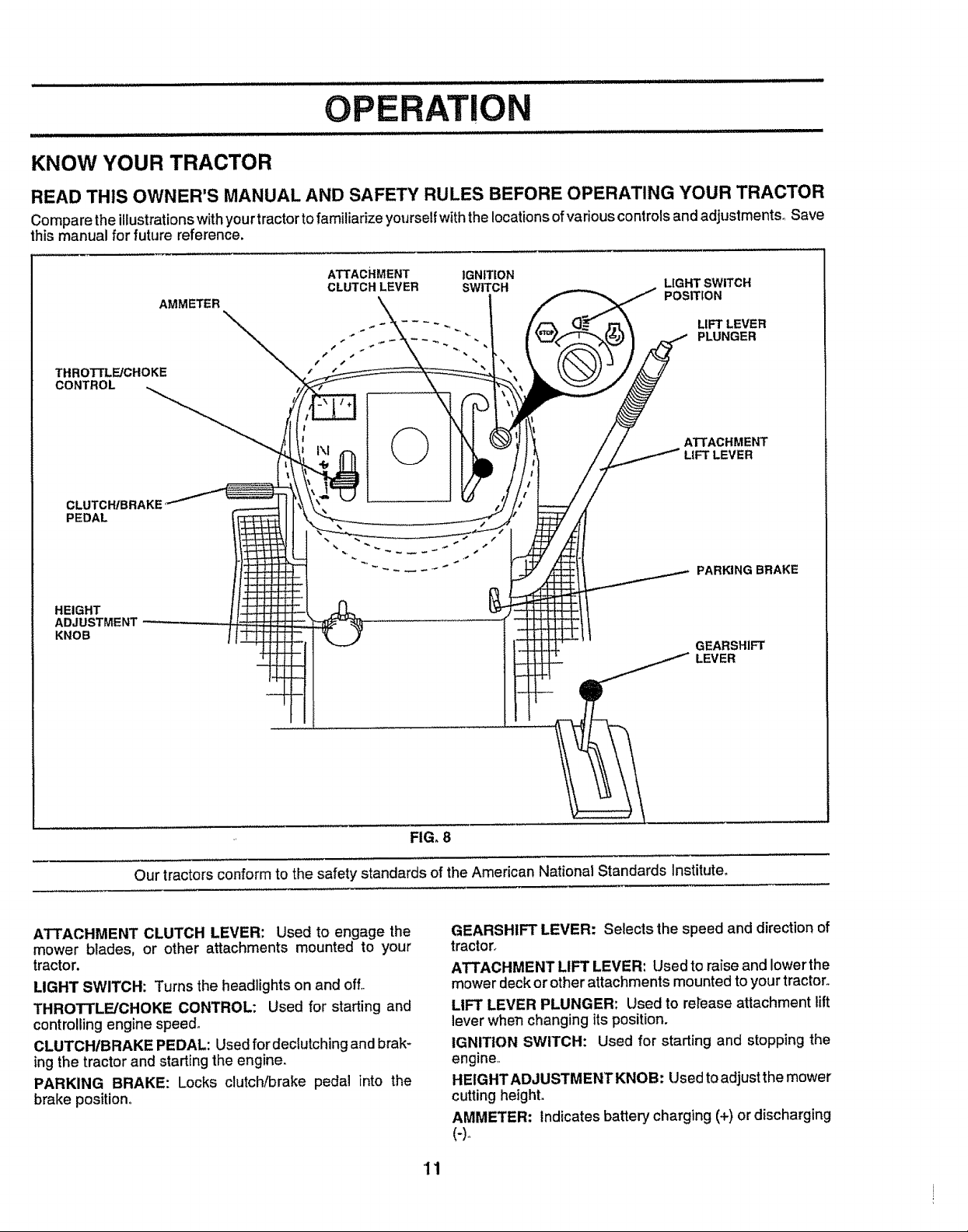
KNOW YOUR TRACTOR
READ THIS OWNER'S MANUAL AND SAFETY RULES BEFORE OPERATING YOUR TRACTOR
Compare the illustrationswithyour tractor to familiarizeyourself withthe locations of various controls and adjustments_ Save
this manual for future reference.
ATTACHMENT IGNITION
CLUTCH LEVER SWITCH LIGHT SWITCH
AMMETER POSITION
.. - PLUNGER
THROTTLE/CHOKE
CONTROL
\" _-\\.,.\\.,,.\ ~ LIFT LEVER
CLUTCH/BRAKE
PEDAL
HEIGHT
ADJUSTMENT
KNOB
!
' ©
FIG. 8
Our tractorsconform to the safety standards of the American National Standards Institute,
A'I-I'ACHMENT
LIFT LEVER
PARKING BRAKE
GEARSHIFT
LEVER
ATTACHMENT CLUTCH LEVER: Used to engage the
mower blades, or other attachments mounted to your
tractor.
LIGHT SWITCH: Turns the headlights on and off,
THROTTLE/CHOKE CONTROL: Used for starting and
controlling engine speed,
CLUTCHIBRAKE PEDAL: Used fordeclutching andbrak-
ing the tractor and starting the engine.
PARKING BRAKE: Locks clutch/brake pedal into the
brake position°
GEARSHIFT LEVER: Selects the speed and direction of
tractor_
ATTACHMENT LIFT LEVER: Used to raiseand lowerthe
mower deckor other attachments mounted to your tractor.
LIFT LEVER PLUNGER: Used to re_easeattachment tilt
lever when changing its position.
IGNITION SWITCH: Used for starting and stopping the
engine,,
HEIGHTADJUSTMENTKNOB: Used toadjustthe mower
cutting height.
AMMETER: indicates battery charging (+) or discharging
(-)_
'11
Page 12
The operation of any tractor can result in foreign objects thrown into the eyes, which can
result in severe eye damage. Always wear safety glasses or eye shields while operating your
tractor or performing any adjustments orrepairs. We recommend a wide vision safety mask
over the spectacles or standard safety glasses.
HOW TO USE YOUR TRACTOR
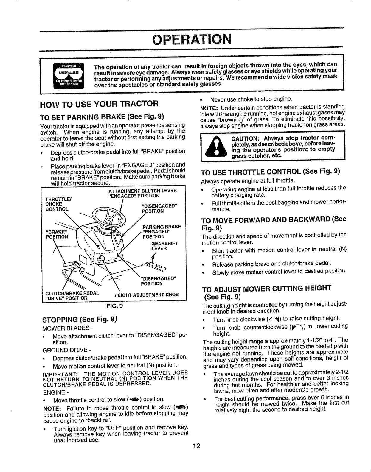
TO SET PARKING BRAKE (See Fig. 9)
Your tractor isequipped withan operator' presence sensing
switch., When engine is running, any attempt by the
operator' to leave the seat without first setting the parking
brake will shut off the engine.
= Depress clutch/brake pedal intofull "BRAKE" position
and hofd_
Placeparking brake lever in"ENGAG ED" position and
release pressure fromclutch/brake pedal. Pedal should
remain in "BRAKE" position. Make sure parking brake
wil! hold tractor secure.
ATTACHMENT CLUTCH LEVER
THROTTLE/
._ / "DISENGAGED"
.BRAKE,_'_-_'_
"'_ _/_ /"ENGAGED
"ENGAGED"POSITION
_J. POSITION
"\\ -t' / POSiT,oN
PO__
, "_\', _ _/_ / GEARSHIFT
"DISENGAGED"
.................. i i i ii ii i i ill,llll,l, IIHI L ,1/
, Never use choke to stop engine.
NOTE: Under certain conditions when tractor is standing
idle with the engirle running, hot engine exhaust gases may
cause browning of grass_ To eliminate this possibility,
always stop engine when stopping tractor on grass areas.
CAUTION: Always stop tractor com-
pletely, as described above, before leav-
I&
rng the operator's position; to empty
grass catcher, etc.
....................... H ..... •
TO USE THROTTLE CONTROL (See Fig. 9)
Always operate engine atfull throttle.
• Operating engine at less than full throttle ['educes the
battery charging rate,
• Full throttle offers the best bagging and mower' perfor-
mance.
TO MOVE FORWARD AND BACKWARD (See
Fig. 9)
The directionand speed of movement is controlledby the
motion control lever_
= Start tractor with motion control lever in neutral (N)
position_
- Release parking brake and clutch/brake pedal.,
• Slowly move motion control lever to desired position.
CLUTCH/RRAKE PEDAL
"DRIVE" POSITION
HEIGHT ADJUSTMENT KNOB
FIG. 9
STOPPING (See Fig. 9)
MOWER BLADES -
• Move attachment clutchlever to "DISENGAGED" po-
sition.
GROUND DRIVE -
• Depress clutch/brake pedal into fuII"BRAKE" position.
. Move motion control lever to neutral (N) position.
IMPORTANT: THE MOTION CONTROL LEVER DOES
NOT RETURN "1"ONEUTRAL (N) POSITION WHEN THE
CLUTCH/BRAKE PEDAL IS DEPRESSED.
ENGINE -
. Move throttle control to slow (o€_) position.
NOTE: Failure to move throttle control to slow (,,ll)
position and allowing engine to idle before stopping may
cause engine to "backfire"_
° Turn ignitionkey to "OFF" position and remove key.
Always remove key when leaving tractor to prevent
unauthorized use..
TO ADJUST MOWER CUTTING HEIGHT
(See Fig. 9)
The cutting height iscontrolled byturning the height adjust-
ment knob in desired direction.
• Turn knob clockwise (('-_) to raise cutting height.
• Turn knob counterclockwise (b#'_)to lower cutting
height.,
The cutting height range is approximately 1-1/2" to 4". The
heights are measured from the ground to the blade tip with
the engine not running. These heights are approximate
and may vary depending upon soil conditions, height of
grass and types of grass being mowed_
° The average lawn should be cut to approximately 2-1/2
inches during the cool season and to over 3 inches
during hot months° For healthier-and better looking
lawns, mow often and after moderate growth.
° For best cutting performance, grass over 6 inches in
height should be mowed twice. Make the first cut
relatively high; the second to desired height
12
Page 13

i i, i,,i,iiiii Jllllllll, ii i iii ii iiiii i ii iiiiii illl i illl Hmll ii
OPERATION
TO OPERATE MOWER (See Fig. 10)
Your tractor is equipped withan operator presence sens-
ing switch+ Any attempt by the operator to leave the seat
with the engine running and the attachment clutch engaged
will shut off the engine.
• Select desired height of cuL
• Lower mower with attachment lift control+
° Start mower blades by engaging attachment clutch
control.
• TO STOP MOWER BLADES - disengage attachment
clutch control.
without either the entire grass catcher,
CAUTION: Do not operate the mower
on mowers so equipped, or the dis-
charge guard in place.
ATTACHMENT CLUTCH LEVER
"DISENGAGED" POSITION
"ENGAGED"
POSITION ATTACHMENT
/ / LIFT LEVER
:_ ._, HIGH POSITION
/, '?-"-"-_--__ LOW
,'_--"_\ POSITION
+
IMPORTANT: THE MOTfON CONTROL LEVER DOES
NOT RETURN TO NEUTRAL (N) POSITION WHEN THE
CLUTCH/BRAKE PEDAL IS DEPRESSED+
° To restart movement, slowly release parking brake and
clutch/brake pedal
. Slowly move motion control lever to slowest setting+
° Make all turns slowly°
TO TRANSPORT (See Figs. 8 and 11)
When pushingortowingyourtractor, besure todisengage
transmissionby placingfreewheel controlin freewheeling
position. Free wheel controlis locatedat the rear drawbar
of tractor.
• Raise attachment lift to highest position with attach+
ment lift control°
° Putlfreewheel control knob out and hold inposition by
insertingretainer spring intoforward hole of control rod+
° Do not push or tow tractor at more than two (2) MPH
° To reengage transmission, reverse above procedure.
NOTE: To protect hood from damage when transporting
your tractor on a truck or a trailer, be sure hood is closed
and secured to tractor. Use an appropriate means of tying
hood to tractor (rope, cord, etc.),
RGE
FIG. 10
TO OPERATE ON HILLS
CAUTION: Do not drive up or down
I"A.................................I
• Choose the slowest speed before starting up or down
hills.
• Avoid stopping or changing speed on hills
• If slowing is necessary, move throttle control lever to
slower position.
• If stopping is absolutely necessary, push clutch/brake
pedal quickly to brake position and engage parking
brake+
Move motion control lever to neutral (N) position+
hills with slopes greater than !5 ° and
do not drive across any slope.
FIG, 11
BEFORE STARTING THE ENGINE
CHECK ENGINE OIL LEVEL (See Fig. 17)
. The engine inyour tractor has been shipped, from the
factory, already filled with summer weight oilo
° Check engine oil with tractor on level ground.
• Remove oil fillcap/dipstick and wipe clean, reinsert the
dipstick and screw cap tight, wait for a few seconds,
remove and read oil level If necessary, add oil until
"FULI_" mark on dipstick is reached. Do not overfiII.
° For cold weather operation you should change oil for
easier starting (See OIL VISCOSITY CHART' inthe
Customer Responsibilities section of this manual).
° To change engine oil, see the Customer Responsibili-
ties section in this manual,
13
Page 14
OPERATION
ADD GASOLINE - Move motion controlleverto neutral(N) position°Shub
= Fill fuel tank° Use fresh, clean, regular' unleaded off engine and set parkingbrake.
gasolinewitha minimum of87 octane. (Use of leaded ° Engage transmissionby placing freewheel controlin
gasoline will increase carbon and lead oxide deposits driving position(See "TO TRANSPORT' inthis section
and reduce valve life). Do not mix oil with gasoline, of manual).
Purchase fuel inquantities that can be used within30 • Sitting in the tractor seat, start engine. After the engine
days to assure fuel freshness_ is running, move throttle control to half (1/2) speed.
IMPORTANT: WHEN OPERATING IN TEMPERATURES With motion control lever inneutral (N) position, slowly
BELOW 32_F(0°C), USE FRESH, CLEAN WINTER GRADE disengage clutch/brake pedal.
GASOLINE TO HELP INSURE GOOD COLD WEATHER
STARTING° o Slowly move motion control lever forward, after the
WARNING: Experience indicates that alcohol blended motion control lever to reverse position. After the
fuels (called gasohol or using ethanol or methanol) can tractor moves approximately five (5) feet retum the
attract moisture which leads to separation andformation of motion control lever to the neutra! (N) position, Repeat
acids during storage. Acidic gas can damage the fuel
system of an engine while in storage. To avoid engine
problems, the fuel system should be emptied before stor-
age of 30 days or longer. Drain the gas tank, start the
engine and let it run until the fuel lines and carburetor' are
empty. Use fresh fuel next season. See Storage Instruc-
tions for additional information. Never use engine or
carburetor cleaner productsin the fuel tank or permanent
damage may occur.
illlllll/ nl ............................. .......... .....=
filler neck. Do not overfiU, Wipeoffany
CAUTION: Fill to bottom of gas tank
spilled oil or fuel. Do not store, spill or
use gasoline near an open flame.
,_,,,,,_,_,,,, , _, _,,,,,, ,,,, ,, ....................... _
I
PURGE TRANSMISSION
iiiiiiiiiii jill ...........
freewheel lever while the engine is run-
CAUTION: Never engage or disengage
............ i H IIH jllllllll iu. H
To ensure proper operation and performance, itis recom-
mended that the transmission be purged before operating
tractor for the first time° This procedure will remove any
trapped air inside the transmission which may have devel-
oped during shipping of your tractor.
IMPORTANT: SHOULD YOUR TRANSMISSION REQUIRE
REMOVAL FOR SERVtCE OR REPLACEMENT, tT
SHOULD BE PURGED AFTER REtNSTALLATION
BEFORE OPERATING THE TRACTOR°
• Place tractor safely on level surface with engine offand
parking brake set.
° Disengage transmission by placing freewheel control
in freewheeling position (See 'TO TRANSPORT" in
this section of manual).
o Sitting inthe tractor seat, start engine. After the engine
isrunning, move throttle control to slow (.gll_) position_
Wfth motion control leverinneutrai (N) position, slowly
disengage ctutchJbrake pedal.
. Move motion control leverto full forward position and
hotd for five (5) seconds_ Move lever to full reverse
position and hold for five (5) seconds. Repeat this
procedure three (3) times..
NOTE: During this procedure there will be no movement of
drive wheels. The air isbeing removed from hydraulic drive
system.
ning.
tractor moves approximately five (5) feet, slowly move
this procedure with the motion contro! lever three (3)
times,.
• Your tractor is now purged and now ready for normal
operation.
TO START ENGINE (See Fig. 9)
When starting the engine for the first time or if the engine
has run out offuel, itwill take extra cranking time to move
fuel from the tank to the engine.
• Depress clutch/brake pedal and set parkingbrake,
• Place motion controi lever' in neutral (N) position.
• Move attachment clutchto "DISENGAGED" position_
- Move throttle controlto choke (N) position.
Note: Before starting, read the warm and cold starting
procedures below.
° Insertkeyintoignitionandturnkeyctockwiseto"START"
positionand release key as soon as engine starts. Do
not runstarter continuouslyfor more than fifteen sec-
onds per minute. If the engine does not start after
several attempts, move throttle control to fast (,_,)
position, waita few minutes and try again° Ifenginestill
does not start, move the throttle control back to the
choke (tXI) position and retry'.
WARM WEATHER STARTING (50° F and above)
• When enginestarts, movethethrottlecontroltothefast
(,t_) position_
• The attachments and grounddrivecan now be use& If
the engfne does not accept the load, restarttheengine
and allowit to warm upfor one minuteusingthechoke
as described above.
COLD WEATHER STARTING ( 50° F and below)
° When engine starts, allow engine to runwith the throttle
control in the choke (N) position until the engine runs
roughly, then move throttle controJto fast (,_) position_
This may require an engine warm-up period from
several seconds to several minutes, depending on the
temperature°
HYDROSTATIC TRANSMISSION WARM UP
s Before driving the unit in cold weather, the transmis-
sion should be warmed up as foIIows:
° Be sure the tractor ison level ground_
° Place the motion control lever in neutral
Release the parking brake and let the clutch/brake
slowly return to operating position.
14
Page 15
OPERATION
• Allow one minute for transmission to warm up.
This can be done during the engine warm up MULCHING MOWING TIPS
period.
• The attachments can also be used during the engine
warm-up period after thetransmission hasbeenwarmed
up.
NOTE: If at a high altitude (above 3000 feet) or in cold
temperatures (below 32 F) the carburetor fuel mixture may
need to be adjusted for best engine performance. See "TO
ADJUST CARBURETOR" in the Service and Adjustments
section of this manual.
MOWING TIPS
° Tire chains cannot be used when the mower housing
is attached to tractor.
° Mower should be,properly leveled for best mow!ng
performance. See 'TO LEVEL MOWER HOUSING in
the Service and Adjustments section of this manual,.
• The left hand side of mower should be used for trim-
ming.
• Drive so that clippings are discharged onto the area
thathas been cut. Have the cut area to the right of the
tractor. This will result in a more even distribution of
ctippings and more uniform cutting°
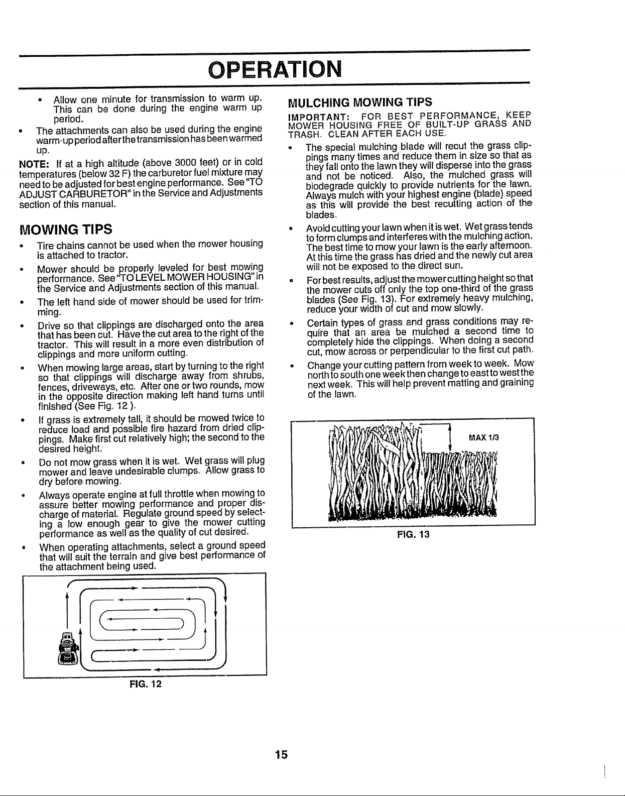
= When mowing large areas, start by turning to the right
so that clippings will discharge away from shrubs,
fences, driveways, etc, After one or two rounds, mow
in the opposite direction making left hand turns until
finished (See Fig. 12 )._
° If grass is extremely tall, it should be mowed twice to
reduce load and possible fire hazard from dried clip-
pings. Make first cut relatively high; the second to the
desired height,
Do not mow grass when it is wet. Wet grass wilt plug
mower and leave undesirable clumps. Allow grass to
dry before mowing.
Always operate engine at full throttle when mowing to
assure better mowing performance and proper dis-
charge of material Regulate ground speed by select-
ing a low enough gear to give the mower cutting
performance as well as the quality of cut desired.
When operating attachments, select a ground speed
that will suit the terrain and give best performance of
the attachment being used,,
f
IMPORTANT: FOR BEST PERFORMANCE, KEEP
MOWER HOUSING FREE OF BU1LT-UP GRASS AND
TRASH° CLEAN AFTER EACH USE.
• The special mulching blade will recut the grass clip-
pings many times and reduce them insize so that as
they fall onto the lawn they will disperse into the grass
and not be noticed. Also, the mulched grass will
biodegrade quickly to provide nutrients for the lawn.
Always mulch with your highest engine (blade) speed
as this will provide the best recurring action of the
blades.
• Avoid cutting your lawnwhen it iswet, Wet grass tends
to form clumps and interfereswith the mulching action.
The best time to mow your lawn is the early afternoon,
At this time the grass has dried and the newly cut area
will not be exposed to the direct sun.
. For best results, adjust the mowercutting height sothat
the mower cuts off only the top one-third of the grass
blades (See Fig, 13). For extremely heavy mulching,
reduce your width of cut and mow slowly°
• Certain types of grass and grass conditions may re-
quire that an area be mulched a second time to
completely hide the clippings. When doing a second
cut, mow across or perpendicular to the first cut path.
° Change your cutting pattern from week to week. Mow
north tosouth one week then change to east to west the
next week, This wili help prevent matting and graining
of the lawn,
MAX 1/3
FIG. 13
1
FIG. 12
15
Page 16

i Replace Oil Filter (If equipped) I
N clean Engine CoolingFIns
1 - Change mere often when operating under a heavy load or in high embtent temperatures
2 - Service mere often when operating in dirty ordustyconditions.
3 - If equipped withoil filter, change oiI every 50 hours.,
4 - Replace bIades mole ellen when mowing insandy soil,
................... i
Replace Spark Plug
Replace Air Ffltet Paper Cartridge
Replace Fuet Ftfter .... I
• = : :
5 -ifequipped w_thadjustable system,
8 ,,Net required ifequipped with maintenance-tree battery
7 * 13ghtenfront axle pivot bolt to 35 ftr-lbs maximum
Do not evettighten
GENERAL RECOMMENDATIONS
The warranty onthistractor does notcover itemsthat have
been subjected to operator abuse or negligence, To
receive fullvalue from thewarranty,operator mustmaintain
tractor as instructed inthis manual,
Some adjustments will need to be made periodically to
properly maintain your tractor..
All adjustments in the Service and Adjustments section of
this manual should be checked at least once each season..
Once a year you should replace the spark plug, clean
or replace air' filter, and check blades and belts for
wear'. A new spark plug and clean air filter assure
proper air-fuel mixture and help your engine runbetter
andlast longer.
BEFORE EACH USE
• Check engine oil level.
o Check brake operation.
• Check tire pressure..
• Checkfor loose fasteners.
LUBRICATION CHART
@
(_) BEARING ZERK
G
CLUTCH
PIVOT(S)
(_) SAE 30 OR 10W30 MOTOR OIL
(_) GENERAL PURPOSE GREASE
® REFER TO CUSTOMER RESPONSIBILITIES "ENGINE" SECTION
IMPORTANT; DO NOT OIL OR GREASE THE PIVOT POINTS
WHICH HAVE SPECIAL NYLON BEARINGS, VISCOUS LUBRI-
CANTS WILL ATTRACT OUST AND DIRT THAT WILL SHORTEN
THE LIFE OF THE SELF-LUBRICATING BEARINGS, IF YOU
FEEL THEY MUST BE LUBRICATED, USE ONLY A DRY, POW-
DERED GRAPHITE TYPE LUBRICANT SPARINGLY,
16
IPINDLE ZERK (_)
"FRONT WHEEL
BEARING ZERK
GEARSHIFT ®
PIVOTS
®
Page 17

CUSTOMER RESPONSIBI
: .... .... ii ill, llllll
TRACTOR
Always observe safety ruleswhen performing any mainte-
nanceo
BRAKE OPERATION
Iftractorrequires more than six(6) feet stopping distance
at high speed {nhighest gear, then brake must be adjusted,
(See 'q_OADJUST BRAKE" in the Service and Adjust-
ments section of this manual).
TIRES
BLADE
MANDREL
TRAILING EDGE
• Maintain proper air pressure in all tires (See "PROD-
UCT SPECIFICATIONS' on page 3 of this manual),.
• Keep tires free of gasoline, oil,or insect control chemi-
cals which can harm rubber,
• Avoid stumps, stones, deep ruts, sharp objects and
other hazards that may cause tire damage.
BLADE CARE
For best results mower blades must be kept sharp. Re-
place bent or damaged blades.
BLADE REMOVAL (See Fig. '14)
• Raise mower to highest position to allow access to
blades.
- Remove hex bolt, lock washer and flat washer securing
blade.
• Install new or resharpened blade with trailing edge up
towards deck as shown.
° Reassemble hex bolt, lock washer and flat washer in
exact order as shown.
• Tighten bolt securely (30-35 Ft° Lbs, torque)
IMPORTANT: BLADE BOLT ISGRADE 8 HEATTREATED.
NOTE: We do not recommend sharpening blade- but ifyou
do, be sure the blade is balanced°
HEX BOLT
(GRADE 8)*
*A GRADE 8 HEATTREATED BOLT CAN BE
IDENTIFIED BYSIXLINES ONTHE BOLT HEADo
FIG. 14
TO SHARPEN BLADE (See Fig. 15)
Care should be taken to keep the blade balanced° An
unbalanced blade willcause excessive vibration and even-
tual damage to mower and engine.
° The blade can be sharpened with afile or on a grinding
wheel. Do not attempt to sharpen while on the mower.
° To check blade balance, you will need a 518"diameter
steel bolt, pin, ora cone balancer. (When using acone
balancer, follow the instructions supplied with bal-
ancer).
• Slide blade on to an unthreaded portion of the steel bolt
or pin and hold the bolt or pin parallel with the ground.
If blade is balanced, it shoutd remain in a horizontal
position. Ifeither end of the blade moves downward,
sharpen the heavy end until the blade is balanced°
NOTE: Do not use a nail for balancing blade. The lobes of
the center hole may appear to be centered, but are not.
17
CENTER HOLE / /
FIG. 15
Page 18

t"
i
i
t
BA'I'rERY
Your tractor has a battery charging system which is suffi-
cient for normal use. However, periodic charging of the
battery with an automotive charger will extend its life.
• Keep battery and terminals clean_
• Keep battery bolts tighL
° Keep small vent holes open (See "CONNECT BAT-
TERY" in the Assembly section of this manual).
• Recharge at 6-10 amperes for1 hour,.
TO CLEAN BATTERY AND TERMINALS
Corrosion and dirt on the battery and terminals can cause
the battery to "leak" power,.
• Open battery box door,,
• Disconnect BLACK battery cable first then RED bat-
tery cable and remove battery from tractor.
• Wash battery with solution of four tablespoons of
baking soda to onegallon ofwater. Be careful not to get
the soda solution into the cells°
° Rinse the battery with plain water and dry.
° Clean terminals and battery cable ends with wire brush
until bright,
° Coat terminals with grease or petroleum jelty,
° Reinstall battery (See "CONNECT BATTERY" in the
Assembly section of this manual)°
V-BELTS
Check V-belts for deteriorationand wear after100 hoursof
operation and replace if necessary_ The belts are not
adjustableo Replace belts ifthey begin to slip from wear,,
NOTE: Although multFviscosity oils (5W30, 10W30 etc.)
improve starting in cold weather, these multi-viscosity oils
will result in increased oil consumption when used above
32°F. Check your engine oil level more frequently to avoid
possible engine damage from running tow on oil
Change the oil after the first two hours of operation and
every 25 hours thereafter or at least once a year if the
tractor is not used for 25 hours inone year'.
Check the crankcase oil level before starting the engine
and after each eight (8) hours of operation, Tighten oil fill
cap/dipstick securely each time you check the oil Level
TO CHANGE ENGINE OIL (See Figs. 16 and 17)
Determine temperature range expected before oil change.
All oif must meet AP1 sewice classification SFor SG,
• Be sure tractor ison level surface.
- Oil wil! drain more freely when warm,
• Catch oil in a suitable container.
• Remove oil fiil cap/dipstick. Be careful not to allow dirt
to enter the engine when changing oil
• Remove drain plug,
• After oil has drained completely, replace oil drain plug
and tighten securely,
° Refillengine with oil through oil fill dipstick tube, Pour
slowly, Do not overfill For approximate capacity see
'PRODUCT SPECIFICATIONS on page 3 of this
manual
- Use gauge onoil lilt cap/dipstick forchecklng level, Be
sure dipstick cap is tightened securely for accurate
reading_ Keep oil at "FULL" line on dipstick.
TRANSAXLE COOLING
Keep transaxle free from build_up of dirt and chaff which
can restrict cooling.
ENGINE
LUBRICATION
Only use high quality detergent oil rated with API service
classification SF or'SGoSelectthe oil's SAE viscosity grade
according to your expected operating temperature,
SAE VISCOSITY' GRADES
.20o 0_
-30° -20_ -10_ 0_ 10_ - _ 20°.... 30=
TEMPERATURE RANGE ANTICIPATED BEFORE NEXT OiL CHANGE
FIG. 16
CAP/DIPSTICK
OIL DRAIN
PLUG
FIG. 17
18
Page 19

CUSTOME NSIBILITIES
AIR FILTER (See Fig. 18)
Your engine will not run properly using a dirty air filter°
Clean the foam pre-cleaner after every 25 hours of opera-
tion or every season, Service paper cartridge every 100
hours of operation or every season, whichever occurs first.
Service air cleaner more often under dusty conditions.
= Remove knob(s) and cover.
TO SERVICE PRE-CLEANER
. Slide foam pre-c_eaner off cartridge.
= Wash itin liquiddetergent and water.
• Squeeze it dry in a clean cloth,,
= Saturate it in engine oil Wrap it in clean, absorbent
cloth and squeeze to remove excess oil
° If very dirty or damaged, replace pre-cleaner.
° Reinstall pre-cleaner over cartridge_
• Reinstall cover and sec[_rewith knob(s).
TO SERVICE CARTRIDGE
° Remove cartridge nut.
° Carefully remove cartridge to prevent debris from
entering carburetor. Clean base carefully to prevent
debris from entering carburetor,
° Clean cartridge bytapping gentlyonflat surface. Ifvery
dirty or damaged, replace cartndge.
o Reinstall cartridge, nut, precleaner, cover and secure
with knob(s).
IMPORTANT." PETROLEUM SOLVENTS, SUCH AS
KEROSENE, ARE NOT TO BE USED TO CLEAN THE
CARTRIDGE THEY MAY CAUSE DETERIORATION OF
THE CARTRIDGE, DO NOT OIL CARTRIDGEo DO NOT
USE PRESSURIZED AIR TO CLEAN OR DRY
CARTRIDGE.
CLEAN AIR SCREEN (See Fig. 19)
Air screen must be kept free of dirt and chaff to prevent
engine damage from overheating. Clean with awire brush
or compressed air to remove dirt and stubborn dried gum
fibers.
ENGINE COOLING FINS (See Fig. 19)
Remove any dust, dirt or oil from engine cooling fins to
prevent engine damage from overheating.
° Remove screws from blower housing and lifthousing
and dipstick tube assembly off engine.
° Cover oil fill opening to prevent entry"of dirt.
° Use compressed air or stiff bristle brush to thoroughly
clean engine cooling fins.
• To reassemble, reverse above procedure.
SCREWS BLOWER
DIPSTICK
TUBE
ASSEMBLY
HOUSING
SCREWS
AIR SCREEN
PLUG
COVER KNOB -""_
COVER __/
FOAM __
PRE-Ct.EANER
FIG. 18
CARTRIDGE NUT
PAPER
CARTRIDGE
ENGINECOOLING FINS
FIG. 19
19
Page 20

MUFFLER
inspect and replace corrodedmuffler and spark arrester (if
equipped) as it could create afire hazard andlor damage.
SPARK PLUGS
Replace spark plugs at the beginning of each mowing
season or after every 100 hours of operation, whichever
occurs first. Spark plug type and gap setting are shown in
"PRODUCT SPECIFICATIONS" on page 3 ofthis manual
IN-LINE FUEL FILTER (See Fig. 20)
The fuel _ter should be replaced once each season. Iffuel
filter becomes clogged, obstructing fuel flow to carburetor,
replacement is required_
• With engine cool, remove filter and plug fuet line
sections°
• Place new fuel filter in position infuel line with arrow
pointingtowards carburetor.
• Be sure there are no fuel line Ieaks and clampsare
properly positioned
• Immediately wipe up any spilled gasoline°
CLAMP
FUEL
FILTER
FIG. 20
CLEANING
• Clean engine, battery, seat, finish, etc. of all foreign
matter.
• Keep finishedsurfaces and wheels free of all gasoline,
oil, etc.
o Protect painted surfaces with automotive type wax.
We do not recommend using a garden hose to clean your
tractor unless the electrical system, muffler, air filter and
carburetor are covered to keep water out. Water in engine
can resultin a shortened engine life.
2O
Page 21

i i ii ,ll,llllll ii,i ,11,,llll,lll,ll,lll,,llllll,ll ii,l/i,illJl,ll,l,/,i,i :: ........................................
SERVICE AND ADJUSTMENTS
CAUTION: BEFORE PERFORMING ANY SERVICE OR ADJUSTMENTS:
Depress clutch/brake pedal fully and set parking brake.
0
Place motion control lever in neutral (N) position.
0
Place attachment clutch in "DISENGAGED" position.
o
Turn ignition key "OFF" and remove key.
o
Make sure the blades and all moving parts have completely stopped.
o
Disconnect spark plug wire from spark plug and place wire where it cannot come in contact
with plug.
I II I1'1]1'1 ,
TRACTOR
TO REMOVE MOWER (See Fig. 21)
Mower will be easier to remove from the right side oftractor,_
• Place attachment clutch in "DISENGAGED" positionn
• Move attachment liftlever forward tolower mower to its
lowest position.,
• Roll belt off engine pulley.
° Disconnect clutch rod from clutch lever by removing
retainer spring.
• Disconnect anti-sway bar from chassis bracket by
removing retainer spring,
° Disconnect suspension arms from rear deck brackets
by removing retainer springs.
, Disconnect front links from deck by removing retainer
springs°
° Raise lift lever to raise suspension arms° Slide mower
out from under tractor.
IMPORTANT', IF AN ATTACHMENT OTHER THAN THE
MOWER IS TO BE MOUNTED TO THE TRACTOR, THE
R,H. AND Loll. SUSPENSION ARMS MUST BE REMOVED
FROM TRACTOR.
TO INSTALL MOWER (See Fig. 21)
• Raise attachment lift lever to its highest position°
• Slide mower under tractor with discharge guard to right
side of tractor.
• Lower lift lever to its lowestposition.
• installmower in reverse order of removal instructions°
CLUTCt
SUSPENSION
RETAINER
SPRING
ANTI-SWAY BAR
LEVER
RETAINER
RETAINER
SPRINGS
(BOTH SIDES)
FIG. 21
21
Page 22

...... llllli,u _ ,,, : i i H,u roll .............: ...... i _,_,l,,i i , .................. i
SERVICE D ADJUSTMENTS
TO LEVEL MOWER HOUSING FRONT_TO-BACK ADJUSTMENT (See Figs. 24 and 25)
Adjust the mower while tractor isparkedon level ground or
driveway. Make sure tires are properly inflated (See
"PRODUCT SPECIFICATIONS" on page 3 ofthis manual).
If tiresare over or underinflated, you will not propedy adjust
your mower.
SIDE-TO-SIDE ADJUSTMENT (See Figs. 22 and 23)
, Raise mower to its highest position,
• At the midpoint of both sides of mower, measure height
from bottom edge of mower to ground. Distance "A' on
both sides of mower' should be the same or within 1/4"
of each other.
- If adjustment is necessary, make adjustment on one
side of mower only.
° To raise one side of mower, tighten lift iinkadjustment
nut on that side.
. To lower one side of mower, loosen lift link adjustment
nut on that side.
NOTE: Each full turn of adjustment nut wil{change mower
height about 1/8",.
° Recheck measurements after adjusting°
BOTTOM EDGE BOTTOM EDGE
OF MOWER TO OF MOWER TO
GROUND GROUND
IMPORTANT" DECK MUST BE LEVEL SIDE-TO-S1DEoIF
THE FOLLOWING FRONT-TO-BACK ADJUSTMENT IS
NECESSARY, BESURETO ADJUST BOTH FRONT LINKS
EQUALLY SO MOWER WILL STAY LEVEL S{DE-TO-
SIDE_
To obtain the best cutting results, the mower housing
should be adjusted so that the front isapproximately 1/4" to
3/4" lower than the rear when the mower is in its highest
position.
Check adjustment on right side of tractor, Measure dis-
tance"D" directly infront and behind the mandrel at bottom
edge of mower housing as shown°
, Before making any necessary adjustments, check that
both front linksare equal in length° Both links should
be approximately 10-3/8'L
° if iinksare not equa( in length, adjust one link to same
length as other link.
o To lower front of mower loosen nut "E" on both front
links an equal number of turns.
,, When distance "D" is 1/4" to 3/4" lower at front than
rear, tighten nuts "F" against trunnion on both front
links,
° To raisefront of mower, loosen nut"F" from trunnion on
both front links. Tighten nut "E" on both front links an
equal number of turns.
• When distance "D" is 1/4" to 3/4" lower at front than
rear, tightennut "F" against trunnionon both front links.
° Recheck side-to-side adjustmenL
GROUND UNE A
FIG. 22
LtFT LINK
ADJUSTMENT NUT
FIG. 23
MANDREL
FIG. 24
BOTHFRONT LINKSMUSTBE EQUAL IN LENGTH
NUT "E"
NUT "F"
FRONT LINKS TRUNNION
22 FIG. 25
Page 23

SERVICE AND ADJUSTMENTS
TO REPLACE MOWER BLADE DRIVE BELT
(See Fig. 26)
The mower blade drive belt may be replaced withouttools,
Park the tractor on level surface. Engage parking brake.
BELT REMOVAL-
• Remove mower from tractor (See 'q'O REMOVE
MOWER" inthis section of this manual).
• Work belt off both mandrel pulleys and idler pulleys_
• Pull belt away from mower_
BELT INSTALLATION -
° Install new belt in reverse order of removal.
° Make sure belt isinall pulley grooves and inside all belt
guides,
• install mower inreverse order of removal instructions,
MANDREL IDLER
PULLEY PULLEYS
MANDREL
PULLEY
FIG. 26
TO ADJUST BRAKE (See Fig. 27)
Your tractor is equipped with an adjustable brake system
which is mounted on the side ofthe transaxle.
If tractor requires more than six (6) feet stopping distance
athigh speed in highest gear, then brake must be adjusted.
• Depress clutch/brake pedal and engage parking brake.
° Measure distance between brake operating arm and
nut "A" on brake rod,
Ifdistance isother than 1-3/4", loosen jam nut and tu rn
nut A until distance becomes 1-3/4'L Retighten jam
nut against nut "A"o
Road test tractor for proper stopping distance as stated
above° Readjust if necessary'. If stopping distanceis
still greater than six (6) feet in highest gear, further
maintenance is necessary. Contact your nearest au-
thorized service center/department.
WITH PARKING BRAKE "ENGAGED"
NUT "A"
NUT
\
ARM
DO NOTTOUCH THIS NUT, IF FURTHER
BRAKE ADJUSTMENTIS NECESSARY
CONTACTYOUR NEAREST AUTHORIZED
SERVICE CENTER/DEPARTMENT
FIG, 27
TO REPLACE MOTION DRIVE BELT
(See Fig. 28)
Park the tractor on level surface° Engage parking brake°
For assistance, there is a belt installationguide decal on
bottom side of left footrest,
• Remove mower (See "TO REMOVE MOWER" in this
section of this manual,,)
• Remove upper belt keeper.
° Remove belt from stationary idler and clutching idler.
• Pull belt slack toward rearof tractor. Carefully remove
belt upwards from transmission input pulley and over
cooling fan blades.
° Put! belt toward front of tractor and remove downward
from around engine pulley°
° Install new belt by reversing above procedure.
IMPORTANT: MAKE SURE UPPER BELT KEEPER IS
POSITIONED PROPERLY BETWEEN LOCATOR TABS,
PULLEY
CLUTCHING
IDLER
STATIONARY"-.
IDLER
TRANSMISSION'
INPUT PULLEY
/ LOCATOR
23
___L'I _....... ,
FIG. 28
Page 24

AND ADJUSTMENTS
TO ADJUST MOTION CONTROL LEVER (See
Fig. 29)
The motion control lever has been preset at the factory and
adjustment should not be necessary°
If for any reason the motion control lever will not hold its
position while at a selected speed, it may be adjusted at the
friction pack located on the _f_;ntside of transmission.
• Park tractor on level surface. Stop tractor by turning
ignition key to "OFF" position, and engage parking
brake.
• Adjust motion control lever by tightening adjustment
locknut one half (1/2) turn,
NOTE= If for any reason the effort to move the motion
control lever becomes too excessive, reverse the above
adjustment procedure by loosening tocknutt/4 to 1/2turn.
Road test tractor after adjustment and repeat procedure if
necessary.
TRANSMISSION REMOVAL/REPLACEMENT
Should your transmission require removal for service or
replacement, it should be purged after reinstallation and
before operating the tractor. See "PURGE TRANSMIS-
SION" in the Operation section of this manual
TO REMOVE WHEEL FOR REPAIRS
(See Fig. 30)
, Blockup axle securely.
° Remove axle cover, retaining ringand washersto allow
wheel removal (rear wheel contains a square key- Do
not lose),
• Repair tire and reassembte_
° On rear wheels only: align grooves in rear wheel hub
and axleo Insert square key.
= Replace washers and snap retaining ring securely in
axle groove.
Replace axle cover,
WASHERS
RETAINING
RING
Q
AXLE COVER
!
SQUARE KEY
(REAR WHEEL ONLY)
FIG. 30
ADJUSTMENT
LOCKNUT
FIG. 29
TO ADJUST STEERING WHEEL ALIGNMENT
If steering wheel crossbars are not horizontal (left to right)
when wheels are positionedstraight forward, remove steer-
ing wheel and reassemble per instructions in the Assembly
section ofthis manual
FRONT WHEEL TOE-IN/CAMBER
The front wheel toe-in and camber' are not adjustable on
your tractor: If damage has occurred to affect the front
wheel toe-in or camber, contact your nearest authorized
service center/department,
TO START ENGINE WITH A WEAK BATTERY
(See Fig. 31)
I A CAUTION: Lead-acid batteries gener- I
! _1_ ate explosive gases. Keep sparks, flame
| _ and smoking materials away from bat- I
I _ teries. Always wear eye protection |
I _ when around batteries° i
............................... i IIIIII ........
tf your battery is too weak to start the engine, it should be
recharged_ ff "lumper cables" are used for emergency
starting, follow this procedure:
IMPORTANT: YOUR TRACTOR IS EQUIPPED WITH A 12
VOLT NEGATIVE GROUNDED SYSTEM. THE OTHER
VEHICLE MUST ALSO BE A 12 VOLT NEGATIVE
GROUNDED SYSTEM, DO NOT USE YOUR TRACTOR
BATTERY TO START OTHER VEHICLES,
TO ATTACH JUMPER CABLES -
° Connect each end of the RED cable to the POSITIVE
(+) terminal of each battery, taking care not to short
against chassis.
o Connect one end of the BLACK cable to the NEGA-
TIVE (_)terminal of futly charged battery.,
= Connect the other end of the BLACK cable to good
CHASSIS GROUND, away from fuel tank and battery.
TO REMOVE CABLES, REVERSE ORDER -
° BLACK cable first from chassis and then from the fully
charged battery.
= RED cable last from both battefles.
24
Page 25

S AND ADJ USTMENT
POSITIVE TERMINAL NEGATIVE TERMINAL
CABLES
__ _._ HOOD
CHARGED
BATTERY
POSITIVE TERMINAL NEGATIVE TERMINAL
FIG. 31
TO REPLACE HEADLIGHT BULB
- Raise hood.
• Pull bulb holder out of the hole in the backside of the
grill.
• Replace bulb inholder and push butb holder securely
back into the hole in the backside of the grill°
• Close hood.
INTERLOCKS AND RELAYS
Loose or damaged widng may cause your tractor to run
poorly, stop running, or prevent it from starting.
° Check wiring. See electrical wiring diagram in the
Repair Parts section of this manual.
TO REPLACE FUSE
Replace with 30 amp automotive-type plug-in fuse. The
fuse holder is located behind the dash.
FIG. 32
ENGINE
TO ADJUST THROTTLE CONTROL CABLE
(See Fig. 33)
The throttle control has been preset at the factory and
adjustment should not be necessary. Check adjustment as
described below before loosening cable° if adjustment is
necessary, proceedas follows:
- With engine not running, move throttle control lever
from slow (.If) to choke (l\l) position. Slowly move
lever from choke (1\1)to fast (,_) position.
° Checkthat holes"A" in governor control lever and hole
in governor plate line-up,, tf holes 'A" are not aligned,
loosen clamp screw and move throttle cable until holes
are aligned. Tighten clamp screw securely.
GOVERNOR GOVERNOR
CONTROL LEVER CONTROL PLATE
TO REMOVE HOOD AND GRILL ASSEMBLY
(See Fig. 32)
- Raise hood_
• Unsnap headlight wire connector.
• Stand infront of tractor. Grasp hood at sides, tilttoward
engine and lift off of tractor,,
° To replace, reverse above procedures°
HOLES "A" CLAMP THROTTLE
SCREW CABLE
FIG. 33
25
Page 26

S RVICE A ADJUSTMENTS
TO ADJUST CARBURETOR (See Fig. 34)
The carburetorhas been preset at the factory and adjust-
merit shouEd not be necessary. However', minor adjust-
ment may be required tocompensatefor differencesinrue!,
temperature, altitude or load. ifthe carburetordoes need
adjustment, proceed as follows:
In general, turning idle mixture vatve in (clockwise) de-
creasesthe supply offue! tothe enginegivingaleaner fuel/
air mixture. Turning the idle mixturevalve out (counter-
clockwise)increases the supplyoffuel tothe enginegiving
a richer fuel!air mixture°
IMPORTANT; DAMAGE TO THE NEEDLE VALVE AND
THE SEAT IN CARBURETOR MAY RESULT IF SCREW IS
TURNED IN TOO TIGHT,,
PRELIMINARY SETTING -
• Air'cleaner assembly must be assembted tothe carbu-
retorwhen making carburetor adjustments°
° Be sure the throttle control cable is adjusted properly
(see above)_
° With engine off turn idle mixture valve in (clockwise)
closing itfinger tight and then turn out (counterclock-
wise) 1 full turn.
FINAL SETTING o
° Start engine and atlow to warmfor five minutes. Make
final adjustments with engine running and shift/motion
control lever' in neutral (N) position.
° Move throttle control lever to slow (-a_) position,, With
finger, rotate and hold throttle lever against idlespeed
screw. Turn idle speed screw to attain 1750 RPM.
o While still holding throttle lever against idle speed
screw, turn idle mixture valve in (clockwise) until en-
gine begins to die and then turn out (counterclockwise)
until engine runs rough° Turn valve to a point midway
between those two positions. Release throttle lever.
ACCELERATION TEST -
• Move throttle control lever from slow (,_!) to fast (4)
position. If engine hesitates or dies, turn idle mixture
valve out (counterclockwise) 1/8 turn, Repeattest and
continue to adjust, if necessary, until engine acceler-
ates smoothly.
High speed stop is factory adjusted. Do not adjust -
damage may result.
IMPORTANT: NEVER TAMPER WITH THE ENGINE
GOVERNOR, WHICH IS FACTORY SET FOR PROPER
ENGINE SPEED, OVERSPEEDING THE ENGINE ABOVE
THE FACTORY HIGH SPEED SETTING CAN BE
DANGEROUS_ IF YOU THINK THE ENGINE-GOVERNED
HIGH SPEED NEEDS ADJUSTING, CONTACT YOUR
NEAREST AUTHORIZED SERVICE CENTER/
DEPARTMENT, WHICH HAS PROPER EQUIPMENT AND
EXPERIENCE TO MAKE ANY NECESSARY
ADJUSTMENTS.
i THROTTLE IDLE SPEED
LEVER SCREW
26
IDLE MIXTURE
VALVE
FIG. 34
Page 27

E
Immediately prepare your tractor for storage at the end of
the season or if the tractor will not be used for 30 days or
more,
CAUTION: Never store the tractor with
gasoline in the tank inside a building
where fumes may reach an open flame
or spark, Allow the engine to cool
before storing in any enclosure.
TRACTOR
Remove mower from tractor for winter storage, When
mower is to be stored for a period of time, clean it thor-
oughly, remove all dirt, grease, leaves, etc, Store in a
clean, dry area..
• Clean entire tractor (See"CLEANI NG" inthe Customer
Responsibilities section of this manuaf).
• Inspect and replace belts, if necessary (See belt re-
placement instructionsinthe Service and Adjustments
section of this manual)_
• Lubricate as shown in the Customer Responsibilities
section of this manual.
° Be sure that all nuts, bolts and screws are securely
fastened° Inspect moving parts for damage, breakage
and wear. Replace if necessary,
• Touch up all rusted or chipped paint surfaces; sand
lightly before painting.
BATTERY
• Fully charge the battery for storage.
° After a period of time instorage, battery may require
recharging.
° To help prevent corrosion and power leakage during
long periods of storage, battery cables should be
disconnected and battery cleaned thoroughly (see'q'o
CLEAN BATTERY AND TERMINALS" in the Cus-
tomer Responsibilities section of this manual).
° After cleaning, leave cables disconnected and place
cables where they cannot come in contact with battery
terminals°
• Be sure battery drain tube is securely attached.
° If battery is removed from tractor for storage, do not
store battery directly on concrete or damp surfaces.
ENGINE
FUEL SYSTEM
IMPORTANT: IT IS IMPORTANT TO PREVENT GUM
DEPOSITS FROM FORMING IN ESSENTIAL FUEL
SYSTEM PARTSSUCH AS CARBURETOR, FUEL FILTER,
FUEL HOSE, OR TANK DURING STORAGE. ALSO,
EXPERIENCE INDICATES THAT ALCOHOL BLENDED
FUELS (CALLED GASOHOL OR USING ETHANOL OR
METHANOL) CAN ATTRACT MOISTURE WHICH LEADS
TO SEPARATION AND FORMATION OF ACIDS DURING
STORAGE. ACIDIC GAS CAN DAMAGE THE FUEL
SYSTEM OF AN ENGINE WHILE IN STORAGE,
° Drain the fuel tank,
° Start the engine and let it run until the fuel lines and
carburetor are empty°
° Never use engine orcarburetor cleaner products in the
fuel tank or permanent damage may occur°
• Use fresh fuel next season,,
NOTE: Fuel stabilizer is an acceptable alternative in
minimizing the formation of fuel gum deposits during stor-
age., Add stabilizer to gasoline in fuel tank or storage
container. Always follow the mix ratio found on stabilizer
container, Run engine at least 10 minutes after adding
stabilizer to allow the stabilizer to reach the carburetor, Do
not drain the gas tank and carburetor ifusing fuel stabilizer.
ENGINE OIL
Drain oil (with engine warm) and replace with clean engine
oil (See "ENGINE" in the Customer Responsibilities
section of this manual).
CYLINDERS
- Remove spark plug(s).
° Pour one ounce of oil through spark plug hole(s) into
cylinder(s),
• Turn ignition key to"START" position for a few seconds
to distribute oil.
° Replace with new spark plug(s).
OTHER
• Do not store gasoline from one season to another,
° Replace your gasoline can if your can starts to rust.
Rust and/or dirt in your gasoline will cause problems,
° If possible, store your tractor indoors and cover it to
give protection from dust and dirt.
• Cover your tractor with a suitable protective cover that
does not retain moisture° Do not use plastic. Plastic
cannot breathe which allows condensation to form and
will cause your tractor to rust.
IMPORTANT: NEVER COVER TRACTOR WHILE ENGINE
AND EXHAUST AREAS ARE STILL WARM,.
27
Page 28

TROU
ii ........
DOTING POINTS
................ ,', _,,_,,,,,, = i=l== i ill ii =l=l L i ii .................. .: ....
PROBLEM
Will not start
Hard to start
Engine will not turn over
CAUSE
1,, Out of fuel
2o Engine not"CHOKED" properly.
3,, Eng{ne floodedv
44 Bad spark plug,
5_ D{rty air filter.
6_ Dirty fuel filter,
7, Water in fuel.
B. Loose or damaged wiring
9_ Carburetor out of adjustment.
10, Engine valves out of adjustment.
1, Dirty air liiter,
2 Bad spark plug.
3 Weak ordead battery.
4 Dirtyfuel filter_
5 Stare or dirty fuel..
6 Loose ordamaged wiring
7, Carburetor out of adjus_nent
8. Engine valves out of adjustment,
1. Clutch/brake pedal not depressed
2 Attachment clutch [s engaged.
3. Weak ordead batter].
4, BJewn fuse.
5. Corroded battery terminals,
6 Loose or damaged wiring,
7. Faulty ignitionswitch
B. Fault,] solenold or starter,
9, Faully operator presence switch(as)
CORRECTION
1. Fill fuet tank.
2 See "TO START ENGINE" in Operation section
3_ Wait several minutes before attempting to start.
4, Reptace spark plug.
5 Cleardreplaee air filter.
6. Replace fuel filler,
7 Drain fuel tank and carburetor, refill tank with fresh
gasoline and replace fuel filter.
B Check all wiring.
9, See "To Adjust Carburetor" in Service Adjustments
section.
10 Contact an authorized service centertdepartment,
1,, Clean/replace air filter
2, Replace spark plug,
3 Recharge or replace battery,,
4_ Reptace fuel filter
5, Drain fuel tank and refill with fresh gasoline
6. Check all wiring.
7, See "To Adjust Carburetor" in Service Adjustments
section.
8_ Contact an authorized service centar/department,.
1,, Depress clutch/brake pedal,
2 Disengage attachment clutch,
3_ Recharge or replace battery_
4, Replace fuse,,
5,. Clean battery terminals.
6. Check all wiring.
7 Check/replace ignition switch.
8,, Check/replace solenoid or starter_
9. Contact an authorized service centerldepartment
Engine clicks but will not
start
Loss of power
Excessive vibration
1,. Weak or dead battery,
2. Corroded battery terminals,
3 Loose or damaged wiring
4. Faulty solenoid or starter,
1,. Cutting too much grassttoo fast,
2. Throttle in "CHOKE" position.
3, Build-up of grass, leaves and trash under mower.
4. Dirty air fiftero
5 Low oil leveVdirty oil,
6. Faulty spark plug_
7,. Dirty fuel fiiter.
8. Stale or dirty fuel.
9 Water in fuel
10,, Spark plug wireloose
t 1. Dirty engine air screen/fins.
12. Dirtylciogged muffler,
13, Loose o_*damaged wiring,
14. Carburetor out ef adjustment
t 5. Engine valves out of adjustmenL
1. Worn, bent or loose btade.
2, Bent blade mandrel,
3. Loose/damaged part(s).
28
1, Recharge or replace battery,
2. Ctean battery termtnals_
3, Check all wiring,
4,, Checldrepface solenoid or starter,,
1_ Set tn "Higher Cut" position/reduce speed,
2, Adjust throttlecontrol
3. Clean underside of mower housing,
4. Clean/_'eptace air filter_
5 Check oi_level/change eli
6 Crean and regap or change spark plug
7, Reptace fuel filter_
8 Drain fuel tank and refitl with fresh gasoline,
9 Drain fuel tank and carburetor, refifl tank with fresh
gasoline and replace fuel filter.
t0 Connect and tighten spark plug wire,,
11 Clean engine air screen/fins.
12, Cleanireptace muffle_,
13 Check a_lwiring.
14. ,, See "To Adjust Carburetor" [n Service Adjustments
section.
15 Contact an authorized service center/department
I Replace blade Tighten blade bolt
2, Reptace btade mandrel
3, Tighten loose part(s), Replace damaged parts,.
Page 29

TROUBLESHOOT!
ii ]llll,ll,i/ ii i i ll,lll,,_,_ ......... ill ....................._.....................................
POINTS
PROBLEM
Engine continues to run
when operator !eaves seat
with attachment clutch
engaged
Poorcut-uneven
u i i i, iIII,IIIIJlHI, illl
Mower blades wt!! not
rotate
Poor grass discharge
CAUSE
_. Faulty operator-safety presence con!rot system,
1, Worn, bent or loose blade.
2, Mower deck not level,.
3. Buildup of grass, leaves, and trash under mower.
4., Bent blade mandrel
5, Clogged mower deck vent holes from buildup of
grass, leaves, and trash around mandrels
!, Obstruction in clutch mechanism
2- Wom,/damaged mower drive bell
3.. Frozen idler pulley.
4, Frozen blademandrel
1. Engine speed too slow,
2,, Travel speed too fast.
3. Wet grass,
4. Mower deck not leve!,
5. Low/uneven tire air pressure,,
6. Worn, bent or loose biade,
7. Buildup of grass, leaves and trash under mower
8. Mower drive belt worn,
9. Blades improperly Installed.
10. lmpreper blades used.
I1 ,, Ctogged mower deck vent holes from buildup of
grass, leaves, and trash around mandrels.
CORRECTION
i lllll,,,,,,,,uiill
t, Check wiring, switches and connections, If not
corrected, contact an authorized service centart
department,,
I. Replace blade, Tighten blade bolt
2, Levelmower deck.
3, Clean underside of mower housing,
4_ Replace blade mandrel,
5 Clean around mandrels to open vent holes,,
1, Remove obstruction,
2, Replace mower ddve belt
3_ Replace Idler pulley,,
4, Replace b_ade mandrel,
1. Place throttlecontrol in "FAST" position,,
2, Shift to slower speed.
3 Allow grass to dry before mowing
4, Level mower deck_
5,, Check tires for proper air pressure.
6o Replace/sharpen blade, Tighten blade bolt,
7,. Clean underside of mower housing
8. Replace mower drive belto
9,, Reinstall blades sharp edge down
10. Replace with blades listed In this manual,
11 Clean around mandrels to open vent holes,
Headlight(s) not working
(if so equipped)
Battery will not charge
Engine "backfires"
when turning engine
"OFF"
roll i i=l=l=l=,H i=
1., Switch Is"OFF"o
2. Bulb(s) bumed ouL
3. Faulty light switch.
4. Loose or damaged widng
5 Blown fuse,,
1,, Bad battery ceil(s),
2. Poor cable connections,
3, Faulty regulator (If so equipped),
4. Faulty alternator.
1. Engine throttlecontrol not set at =SLOW"
position for 30 seconds before stopping engine,
1,. Turn switch "ON",,
2, Replace bulb(s)_
3 Check/replace light switch°
4. Check wtdng and connections.
5, Replace fuse
1. Replace battery.
2, Check/clean allconnections.
3, Replace regulator,
4, Replace aItemator.
1, Move throttleconlrol to "SLOW" position and allow
to tdIe for 30 seconds before stopping engine,
29
Page 30

SERVICE NOTES
30
Page 31

SCHEMATIC
TRACTOR - - MODEL NUMBER 917.258530
RED
RED
AMMETER
WHITE
RE__2L
IGNITION
SWITCH
IGNITION SWITCH
POSITION CIRCUIT "MAKE"
OFF G + M + L NONE
RUN/LIGHT B + L ........A + Y,,
RUN B + L NONE
START B + L + S NONE
1,,,
BtACK
BATTERY
l I
FUSE30 AMP,
1 I
RED
STARTER
r---t
'O ', O', .......
" _ ! _ SOLENOID
CLUTCH1BRAKE
(PEDALUP) WHITE
WHITE _ t
t _ | -1 F-
J
SEAT SWITCH
(NOT OCCUPIED)
I I
I
BLACK L_ l
GROUNDING
"_ A HOUR"t.,--, I" CONNECTOR
(OPTIONAL)
BLUE _
I 1
1 _1
AFTER FIRE SOLENOID
BROWN
BLUE
ORANGE
BLACK
(_ IGNITION _ SPARK
CHARGING SYSTEM OUTPUT
3 AMP DO @ 3600 RPM
LIGHTING SYSTEM
UNIT PLUGS
28 VOLTS AC MIN, @ 3600 RPM
(CHARGING SYSTEM DISCONNECTED)
!
| | | HEADLIGHTS
NOTE
YOUR TRACTOR IS
EQUIPPED WITH A SPECIAL
ALTERNATOR SYSTEM_
THE LIGHTS ARE NOT
CONNECTED TO THE
BATTERY, BUT HAVE THEIR
OWN ELECTRICAL SOURCE,
BECAUSE OF THIS, THE
BRIGHTNESS OF THE LIGHTS
WILL CHANGE WITH ENGINE
SPEED. AT IDLE THE LIGHTS
WILL DIM. AS THE ENGINE IS
SPEEDED UP, THE LIGHTS
WILL BECOME THEIR BRIGHTEST,
SWITCH __--_
(OFF)
©
NON-REMOVABLE REMOVABLE
CONNECTIONS CONNECTIONS F
WIRING INSULATED CLIPS
NOTE: IFWIRING INSULATED
CLIPS WERE REMOVED FOR
SERVICING OF UNIT, THEY
SHOULD BE REPLACED TO
PROPERLY SECURE YOUR WIRING.
BLACK
L
F
)
)
)
I
)
P
P
31
Page 32

REPAIR PARTS
ELECTRICAL
19
TRACTOR - - MODEL NUMBER 917.258530
aT_Jr_
21
/
\I
26
\
i
/
t
/
32
I
/
/
I
/
6
I +t\
I
32
Page 33

REPAIR PARTS
ELECTRICAL
TRACTOR-- MODEL NUMBER 917.258530
KEY PART
NO. NO. DESCRIPTION
1 146139
2 747604!2
3 STD551025
4 STD551125
6 STD541025
7 109238X
8 156417
9 109596X
t6 153684
19 STD551125
20 73350400
2t 147430
22 4152J
24 4799J
25 146147
26 108824X
28 4207J
29 121305X
30 140301
31 124211X
32 141226
33 109310X
40 156442
41 71110408
42 131563
43 145673
44 73640400
45 121433X
52 141940
70 140422
NOTE: All component dimensions given in U.S. inches
1 inch = 25°4 mm
Battery 12 Volt 25 Amp
Bolt, Hex Head 1/4-20 unc x 3/4
Washer
Washer
Nut
Tube, Plastic, 12"
Case, Battery Mech Hinge
Clamp, Hose
Switch, {nterlock Push-In
Washer, Lock
Nut, Hex, ,Jam 1/4-20 UNC
Harness, Light Socket
(includes 4152J)
Bulb, Light
Cable, Battery, 6 Gauge, Red, 11"
Cable, Battery, 6
Wire
Fuse, 30 Amp
Cable, Ground, 6 Gauge, Black, 12"
Switch, Plunger
Switch, Ignition
Nut, ignition
Cover, Key Switch
Key, Ignition
Harness, Ignition
Bolt, Hex Head, Fin,, t/4-20 x 1/2
Cover, Terminal, Red
Solenoid
Nut Keps BIk Hex 1/4_20 UNC
Ammeter Rectangular 6 Amp
Protection Wire Loop
Harness Engine B&S
Gauge, Red, W/16
33
Page 34

REPAIR PARTS
TRACTOR -- MODEL NUMBER 917.258530
CHASSIS AND ENCLOSURES
28
12
6O
3 /
74
38_3 _ 39
3
34
14
Page 35

REPAIR PARTS
TRACTOR - - MODEL NUMBER 917.258530
CHASSIS AND ENCLOSURES
KEY PART
NO. NO. DESCRIPTION
1 153871
2 140356
3 17490612
4 19131216
5 155272
9 150156)(011
10 STD533710
11 "146956
12 145660
I3 146962
!4 1749O608
!7 144983X558
18 126938X
25 19131312
26 STD541437
28 145198X558
29 145200
3O 151287}<558
31 139976
38 139886
39 139887
51 73800400
52 1909'14i6
53 145201
54 17030814
55 1452O2
57 STD522507
60 STD533707
64 154798
74 STD541437
140 150556
142 156095
143 154966
144 154207
146 154334
+- 5479J
Chassis Assembly
Drawbar
Screw, Thd. Roll. 3/8-16 x 3/4
Washer 13/32 x 3/4 x 16Gauge
Bumper Hood/Dash
Dash
Bolt, Carriage 3/8-16 x 3/4
Panel, Dash, L.H.
Clip Tinnerman Grille P/L
Panel, Dash, R.H°
Screw Thdrol 3/8-16 x 1/2
Hood Assembly
Bumper Hood
Washer t3/32 x 13/16 x 12 Gauge
Nut
Grille wlClips MS-558
Lens, Grille
Fend/Ftrest Pnt BTLT N HLD 558
Bracket, Fender Support
Pivot Bracket Assembly, L.Ho
Pivot Bracket Assembly, R.H+
Nut Lock wltnsert 1/4-20 UNC
Washer 9/32 x 7/8 x 16 Ga.
Bracket Grille Pickoff LH
Screw Spiderlock Hex Hd #8-7/8
Bracket Grille Pickoff RH
Bolt, Fin Hex 1/4+20 UNC x .75
Bolt Rdhd Sqnk 3/8+16 UNC x 3/4
Dash Lower STLT
Nut Crownlock 3/8-16 UNC
Bracket Chassis Front
Plate Reinforcement STLT
Bracket Swaybar Chassis
Bracket Pnt Footrest STLT
Screw Torx Hd Thd 5/16-18 UN-2A
Plug, Button
NOTE: All component dimensions given in U,.S°inches
1 inch = 25+4mm
35
Page 36

REPAIR PARTS
DRIVE
TRACTOR - - MODEL NUMBER 917.258530
57
77
15
J
97
•:"_ 98 30
24
26
62
36
12
22
36
61
32
105
37
84100
27
106
10o
Page 37

REPAIR PARTS
TRACTOR - - MODEL NUMBER 917.258530
DRIVE
KEY PART KEY PART
NO. NO, DESCRIPTION NO. NO. DESCRIPTION
1 150071 Transaxle Assembly 63 140186
2 142431 Spring, Return, Brake 64 71170764
3 143995 PuIley, Transaxle 85 STD551143
8 154792 Rod Shift Fender 66 154778
10 STD561210 Pin Cotter 1/8 x I CAD 69 142432
15 74490544 Bolt Hex Ftghd 5/16-18 Gr_5 70 134683
16 STD541431 Nut Lock HexW/Ins. 5/t6-18 Unc 71 140158
18 STD523710 Bolt Fin Hex 3/8-16 Uncx 1 Gr..5 72 19132012
19 STD541437 Nut Lock Hex WiWsh 3/8-16 Unc 73 156347
21 130564 Knob, Deluxe 1/2-13 74 121199X
22 145627 Rod, Brake Hydro 75 121749X
24 73350600 Nut, HexJam 3/8-16 Unc 76 12000001
25 106888X Spring, Brake Rod 77 123583X
26 STD551037 Washer 78 t21748X
27 76020412 Pin Cotter 1/8 x 3/4 CAD_ 81 156046
28 145204 Rod, Parking Brake 82 123782X
29 124236X Cap, Parking Brake 83 19171216
30 t30807 Bracket, Transaxle 84 140548
31 127275X KeeperBelt Lh 86 71208
32 STD523107 Bolt Hex Hd 5/16-18 Unc x 3/4 87 19212016
34 155071 Shaft, Foot Pedal 88 12000008
35 120183X Bearing, Nylon 89 154882
36 STD551062 Washer 91 74780536
37 STD571810 Pin, Roll 92 74780524
38 123674X Pulley, Idler, Flat 93 142564
39 STD523727 Bolt 94 140462
40 4470J Spacer, Split 95 144643
41 154777 Keeper, Belt Retainer 96 STD624003
42 1913t312 Washer 13/32x 13/16 x't2 Gauge 97 140469
47 127783 Pulley, Idler, V-Groove 98 73510600
48 154604 BeNcrankAssembly Clutch 100 19111216
49 123205X Retainer, Belt 102 141322
50 STD523715 Bolt t03 73940800
51 STD541437 Nut Crownlock 3/8-'16 UNC 104 140156
52 STD54143I Nut, Crownlock 5/16-18 Unc 105 71070516
53 105710X Link, Clutch 106 74780520
55 t05709X Spring, Return, Clutch 116 72110610
56 STD523712 Bolt Hex 3/8-16 x 1-1/4 118 154774
57 140294 V-Belt, Ground Drive 121 154419
59 140312 Keeper, Center Span
61 174906t2 Screw Thdrol. 3/8-16 x 3/4 Ty,.TT
62 8883R Cover, Pedal
NOTE: All component dimensions given in U_S..inches
1 inch = 25.4 mm
Pulley, Engine
Bolt 7/16-20 X 4 Gro5
Washer Lock Hvy HIcl Spr 7/16
Keeper Belt Engine
Screw
Keeper Belt Engine
Strap Torque Lh Hydro 18/20" T
Washer '13/32 x 1-1/4 x 12 Gauge
Strap Torque Rh Hydro
Spacer, Split
Washer 25/32 x 1-1/4 x 16 Gauge
E-Ring
Key, Square
Washer 25/32 x 'I-5/8 x 16 Gauge
Shaft Asm. Cross Hydro 20" Tires
Spring Torsion T/A
Washer I7/32 x 3/4 x 16 Ga,,
Rod, Tie Hydro 20" Tires
Bushing Rod Strigo 629/632 ID
Washer 21/32 x 1-1/4 x 16 Ga.
Ring Klip #5304-62
Console, Shift
Bolt Fin Hex 5/16-18 x 2-1/4
Bolt Fin Hex 5/6-18 Unc x i-t/2
Line Fuel Hydro 4"
Fan, Hydro 7"
Contro/Bypass Hydro 20" Tires
Retainer Spring 1" ZtnclCad
Keeper Bolt Rh Hydro 0750° 18/20"
Nut Keps Hex 3/8-16 Unc
Washer 11/32 x3/4 x 16 Ga.
Washer BellvUle .501D x 1o50D
Nut Hex Jam Toplock 1/4-20 Unf
Arm, Control Hydro
Screw Cap Hex 5/16 x 18 x 1
Bolt Fin Hex 5/16_18 Unc x 1-1/4
Bolt Rdhd Sqnk 3/8-16 x 1,25
Spacer Bellcrank
Nyliner Clutching STL
37
Page 38

REPAIR PARTS
STEERING ASSEMBLY
62
TRACTOR - - MODEL NUMBER 917,258530
_41
,,÷ ,~
i-L-:
J
29"
27
J
47
11
40
25
32
28
3O
67
43
38
Page 39

REPAIR PARTS
STEERING ASSEMBLY
TRACTOR - - MODEL NUMBER 917.258530
KEY PART
NO. NO. DESCRIPTION
1 139768
2 154427
3 154422
4 154423
5 6266H
6 121748X
7 19272016
8 12OO0029
9 3366R
10 156438
11 STD551t37
t3 154779
15 739010OO
16 132624
17 156546
18 57079
19 t24035X
2O 126684X
21 STD551125
22 7t 100410
23 127501
25 154406
26 126847X
27 136874
28 19431416
29 17490612
30 STD561210
32 130465
36 155099
37 152927
38 139769
39 191338O8
40 STD541537
41 100711L
42 145O54
43 121749X
44 153720
46 121232X
47 6855M
51 STD541431
54 7478O520
62 156594
63 STD523710
65 154780
66 1544O4
67 74781044
68 154429
NOTE: Ait component dimensions given in U_S.inches
1 inch = 25.4 mm
Steering Wheel
Axle Assembly STMP Dropped STL
Spindle Assembly, Loll.
Spindle Assembly, R.H.
Bearing, Race, Thrust, Hardened
Washer 25/32 x 1-5/8 x 16 Gauge
Washer 27/32 x 1-1/4 x 16 Gauge
Ring, Klip
Bearing, Steering Column
Draglink Extended Stamped
Washer, Lock
Bearing Axle STLT!GT
Nut, Lock, Flange 5/8-11 UNC
Pin,Axle 5/8 x 1.55/1.54
Shaft Assembly, Steering
Washer, Thrust .515 x .750 x .033
Support, Shaft
Washer, Shim 1/4 x 5/8 x ..062
Washer
Screw, Hex Socket Head
1/4-20 x 5/8
Pittman Shaft Assembly
Bracket, Steering
Bushing, Link, Drag
Gear, Sector
Washer 13/32 x 7/6 x 16Gauge
Screw, Thdo, Roll. 3/8-16 x 3/4
Pin
Rod, Tie
Bushing, Steering
Screw
insert, Steering Wheel
Washer 13/32 x 2-3/8 x 8 Gauge
Gripco Nut
Adaptor, Steering Wheel
Boot, Steering Shaft
Washer 25/32 x 1-1/4 x 16 Gauge
Extension Shaft Steering LR.LT
Cap, Spindle
Fitting,Grease
Nut Lock Hex w/ins. 5/16-18 UNC
Bolt Fin Hex 5/16-18 UNC x 1-1/4
Kit Steering Asm Service
Bolt, Fin Hex 3/8-16 UNC x I Gr 5
Spacer Axle
Bearing Arm Pittman
Bolt, Fin Hex 5/8-11 UNC x 2-3/4
Axle, Brace
39
Page 40

REPAIR PARTS
SEAT ASSEMBLY
TRACTOR - - MODEL NUMBER 917,258530
10
KEY
NO.
1
2
3
4
5
6
7
8
9
10
12
13
14
PART
NO.
140123
140551
STD523710
19131610
145006
STD541437
124181X
17490616
19131614
155925
121246X
121248X
72050411
KEY PART
DESCRIPTION NOo NO. DESCRIPTION
Seat
Bracket, Pivot, Seat
Bolt
Washer 13/32 x 1 x 10 Gauge
Clip, Push-In Hinged
Nut
Spring, Seat
Screw, Thd., Roll. 3/8-16 x 1
Washer 13/32 x 1 x 14 Gauge
Pan, Seat Emboss QCK Conn.
Bracket, Switch Mounting
Bushing, Snap
Bolt, Carriage 1!4-20 x 1-3/8
15 134300
16 121250X
17 123976X
21 153236
22 STD541431
23 74780814
24 19171912
25 127018X
26 STD551150
NOTE: All component dimensions given in U.S inches
1 inch = 25,4 mm
Spacer, Split _28x .88
Spring
Locknut, Flange 1/4 Grade 5
Bolt, Shoulder 5/16-t8 UNC
Nut
Bolt, Hex Head, Fin.
1/2-13 x7/8 Grade 5
Washer 17/32 x 1-3/16 x 12 Gauge
Bolt, Shoulder 5/16-18 x .62
Washer, Lock
4O
Page 41

REPAIR PARTS
DECALS
TRACTOR - - MODEL NUMBER 917,258530
21
KEY
NO.
13 2 6 3 18 7 7 18 4
i
14
PART
NO.
DESCRIPTION
KEY PART
NO, NO.
10
2O
21
12 13
DESCRIPTION
1 156811
2 150333
3 151299
4 15130O
6 133644
7 15O927
8 156787
9 146709
I0 156439
12 146046
WHEELS & TIRES
2 _ 5,8
Decal, Oper, Instr.
Decal, Cap Cnsmr Help Line
Decal, Hood, R.H.
Decal, Hood, L.H.
Decal, Customer Maintenance
Decal, Side Panel
Decal, Deck Mower EZ3
Decal, Fender, Craftsman
Decal, Fender Danger
Decal, V-Belt Drive Schematic
4,10
7
13 147138
!4 136832
18 151708
2O 149516
21 15681O
-- 138311
-- 142341
-- 154515
-- 154516
-- 156788
-- 156789
KEY PART
NO. NO. DESCRIPTION
1 59192 Valve Cap, Tire
2 65139 Stem, Valve
3 106222X Tire, Front
4 59904 Tube, Front Tire
1I
5 106732X427 Rim, Front
6 278H Fitting, Grease (Front Wheel Only)
7 9040H Bearing, Flange (Front Wheel Only)
8 106108X427 Rim, Rear
9 122082X Tire, Rear
10 7152J Tube, RearTire
11 104757X Cap, Axle
- - 144334 Sealant, Tire 10 oz.
NOTE: All component dimensions given in U.S. inches
I inch = 25.4 mm
Decal, Chassis, 6 Speed/42"
Decal, V-Belt Schematic
Decal, Ins. Hood
Decal, Battery Dngr/Psn Eng
Decal, Fender Auto
Decal, Lift Handle
Decal, Drawbar Cntrl Mvt Hyd LT
Pad Footrest LH STLT
Pad Footrest RH STLT
Owner's Manual, English
Owner's Manual, Spanish
(Not Provided, Service Item Only)
(Not Provided, Service Item Only)
41
Page 42

REPAIR PARTS
ENGINE
TRACTOR =- MODEL NUMBER 917.258530
3
81
31
4O
29
\
OPTIONAL EQUIPMENT
38 78
_-3 _., _9 _'_
r
33
37
23
35
Spark Arrester
42
Page 43

REPAIR PARTS
ENGINE
TRACTOR -- MODEL NUMBER 917.258530
KEY PART
NO. NO. DESCRIPTION
12150600
1772041O
4 137352
13 272293
14 1328O324
15 t3200300
16 STD551237
23 156123
29 13718O
31 109202X
32 123549X
33 123487X
35 17490512
37 137040
38 .......
4O 124028X
44 17490412
46 190914t6
62 STD551131
72 71070512
78 17490620
81 128861
NOTE: All component dimensions given in U,Soinches
1 inch = 25.4 mm
Control, Throttle
Screw, Hex Head, Thread Cutting
1/4-20 x 5/8
Engine (See Breakdown) Briggs
Model 28N707-0173-01
Muffler
Gasket, Exhaust
Nipple, Pipe 3t8 NPT x 3
Elbow, Standard 90°, 3/8-18 NPT
Washer
Shield, Heat
Arrestor, Spark
Tank, Fuel
Cap Assembly, Fuel Tank, Vented
Clamp, Hose
Screw Thdrol 5/16-18 x 3-4 Tyt
Line, Fuel
Plug, Oil Drain
(Order From Engine Manufacturer)
Bushing, Snap, Fuel Line
Screw, Hex Washer Head, Thd,.,Roll
1/4-20 x 3/4
Washer 9/32 x 7/8 x 16 Gauge
Washer, Lock
Screw, Hex Cap Head 5/16-18 x 3/4
Screw, Thd. Roll. 3/8-16 x 1-1/4
Nut Flange 1/4-20 Starter Nut
43
Page 44

REPAIR PARTS
MOWER LIFT
TRACTOR =- MODEL NUMBER 917.258530
28
13
27
26
24
23
7
5
4
49
13
19
32
6
5
13
\
19
32
2O
15
161718 20
20
15
44
Page 45

REPAIR PARTS
MOWER LIFT
TRACTOR - - MODEL NUMBER 917.258530
KEY PART
NO. NO. DESCRIPTION
1 136973 Lift Lever Inner Wire Assembly
2 1451t7 Shaft Assembly, Lift
3 105767X Pin, Groove
4 12000002 E-Ring
5 192t162! Washer 21/32 x 1x 2! Gauge
6 120183X Bearing, Nylon
7 125631X Grip, Handle, Fluted
8 122365X Button, Plunger, Red
t0 122512X Spring
11 139865 Link, Lift, LoHo
12 139866 Link, Lift, R.H.
13 STD624008 Retainer Spring
15 127218 Link, Front
16 73350800 Nut, Hex, Jam 1/2-13 UNC
17 130171 Trunnion
18 73800800 Locknut, Hex, with Washer Insert
1/2-13 UNC
19 139868 Arm, Suspension, Rear
20 STD624008 Retainer Spring
23 110807X Nut, Special
24 19131016 Washer 13/32 x 5/8 x 16 Gauge
25 2876H Spring
26 76020308 Pin, Cotter 3/32 x 1/2
27 126971X Rod, Adjust, Lift
28 73350600 Nut, Hex, Jam 3/8-16 UNC
29 138057 Knob, Infinite Height Adjustment
30 i50233 Trunnion, Inf Height
31 140302 Bearing,Pvt, Lift Spherical
32 73540600 Nut, Crownlock 3/8-,24
49 145212 Nut Hex Flange Lock
NOTE: All component dimensions given in U.S_inches
1 inch= 25.4 mm
45
Page 46

REPAIR PARTS
MOWER DECK
76
TRACTOR - - MODEL NUMBER 917.258530
53
113 111 114
.116 \ \ _f I
58 35
\
2
16
,02
34
33
32
105 ._''104
106
27
_p_7/_129
92_@_. 3 "_ 92
19 / _/.
21
18
13_-
)
9---_
46
Page 47

REPAIR PARTS
TRACTOR - - MODEL NUMBER 917.258530
MOWER DECK
KEY PART KEY PART
NO. NO, DESCRIPTION NO. NO. DESCRIPTION
1 144393
2 STD533t07
3 138017
4 138440
5 STD624008
6 130832
8 85O857
9 STD55t137
10 14O296
11 134149
12 129895
13 t37645
14 128774
15 t10485X
16 140329
17 7211061O
18 STD533106
19 132827
20 136888
21 STD54t431
22 134753
23 131267
24 105304X
25 123713X
26 110452X
27 130968
28 !9"111016
29 131491
30 138776
31 129963
32 153535
33 137266
34 STD533717
35 133835
36 131494
37 STD55t037
4O STD541437
41 133551
43 140083
44 140O88
45 STD624003
46 137729
48 133944
49 133940
50 131340
51 STD541410
52 139888
53 131845X900
54 133943
55 140084
56 122052X
Mower Housing 58
Bolt 59
Bracket Assembly,Sway Bar, Front 67
Bracket Assembly, Sway Bar 68
Retainer Spring 71
Arm, Suspensuon, Rear 72
Bolt, Hex 3/8-24 x 1.25 Grade 8 73
Washer, Lock 74
Washer, Hardened 75
Blade, Mulching 76
Bearing, Ball 77
Shaft Assembly, Mandrel, Vented 78
(Includes Key Number 6) 79
Housing, Mandrel, Vented 80
Bearing, Ball, Mandrel 81
Stripper, Vented Mower Deck 82
Bolt, Carriage 3/8-16 x 1-1/4 83
Bolt, Carriage 5/16-18 x 5/8 84
Bolt, Shoulder 85
Baffle, Vortex 92
Nut Crown!ock 5/!6-18 UNC 101
Stiffener Bracket !02
Bracket, Deflector t03
Cap, Sleeve t04
Spring, Torsion, Deflector 105
Nut, Push 106
Shield, Deflector 11'1
Washer 11/32 x 5/8 x 16 Gauge !12
Rod, Hinge 113
Screw Thdrol Hex Head Zinc Mwr 114
Washer, Spacer 115
Pulley, Mandrel 116
Nut, Topfock, Flanged 1'17
Bolt 118
Fastner, Christmas Tree 119
Pulley, idler, Flat 121
Washer 13/32 x 13/16 x 16 Gauge 128
Nut Crownlock 3/8-16 UNC '129
Rod, Pivot, with Nibs 130
Rod, Clutch, Secondary, with Nibs 131
Guard, Mandrel, Loll. 132
Retainer
Screw, Thd. Roll 1/4-20 x 5/8 - -
Washer, Hardened
Roller Assembly, Cam Follower - -
Bolt, Shoulder #10-24 Grade 5
Locknut
Bolt, Shoulder 5/16-18 UNC
Arm Assembly, Pad, Brake
Washer, Hardened
Arm, Idler
Spacer, Retainer
NOTE: All component dimensions given in U.S inches
140086
141043
149846
144200
142427
131870
127847
121748X
12O00029
1289O3
127845
154809
127498
153701
73350600
142028
120958X
156084
72140618
STD541437
136420
71161010
19061216
STD551110
130758
2029J
155197
155198
17490512
STD541431
72!10504
137644
133957
7393O600
19121414
143723
153390
19131312
STD523710
STD533710
191322O3
130794
145411
1 inch = 25.4 mm
Spring, Torsion Brakes
Guard, TUV Idler
Knob Custom Oval
V_Belt
Rod, Clutch, Primary, with Nibs
Spring, Return
Arm, Clutch, Secondary
Washer 25/32 x 1-5/8 x 16 Gauge
Ring, Klip
Bolt, Shoulder 3/8-16 UNC x 1.44
Keeper, Spring
Lever Asm. Clutch Pri PIm STLT
Bushing, Large, Brass
Spring, Mower Clutch
Nut, Hex Jam 3/8-16 Uric
Trunnion, Adj_
Washer Sintered
Keeper Belt Idler Fixed
Bolt Carriage 3/8-16 x 2-1/4
Nut
Mulcher Cover
Screw
Washer #10
Washer, Lock
Latch Assembly, Bagger
Nut, Weld
Bracket, Gauge, Wheel L.Ho
Bracket, Gauge, Wheel R_H.
Screw Thdrol 5/16-t8 x 3/4
Nut, Hex, Keps 5/16-18 UNC
Bolt, Carriage 5/16 UNC x t/2
Bolt, Shoulder
Wheel, Gauge
Nut, Centerlock 3/8-16
Washer 3/8 x 7/8 x 14 Gauge
Bracket
Washer Felt
Washer 13/32 x 13/16 x 12 Ga.
Bolt, Fin Hex 3/8-16 UNC x I Gr. 5
Bolt, RDHD SQNK 3/8-I6 UNC x 1
Spacer, Washer 13/32 l.D. x 1-3/8
O.D_ x 1/4
Mandrel Assembly (Includes Key
Numbers 8-10, 12-15, 3t and 32)
Mower Deck, Complete (Standard
Deck, Order Separately Mulcher
Plate and Gauge Wheel
Components, Key Nos. 101-106
and 111-121)
47
Page 48

REPAIR PARTS
TRACTOR - - MODEL NUMBER 917.258530
HYDRO GEAR TRANSAXLE - MODEL NUMBER 310-0650
58
26
23
\
19
43
27
90 _3 52 ''--.
91 9
48
17
69
t4
4
5
3
35
"_13
Page 49

REPAIR PARTS
TRACTOR - - MODEL NUMBER 917.258530
HYDRO GEAR TRANSAXLE - MODEL NUMBER 310-0650
KEY PART KEY PART
NO, NO. DESCRIPTION NO. NO. DESCRIPTION
1 142930 Housing, Lower 43 142884 Washer 7/16 x 7/8 x °060
2 !42931 Assembly, Upper Housing 44 150829 DifferentialAssembly
3 142932 Seal, Lip 52 142991 Washer 3/4 x 1.5 x.'t3
4 142928 Ring, Wire Retaining 53 142961 Seal .75 x 1.25 x .250
5 142933 Ring, Retaining 56 142963 Shaft, Input
6 142934 Bearing, Shaft Ball 58 142964 Bolt 1/4-20x 1.38
7 142935 Bearing, Cradle 59 142965 Pin o5OD x .43 ID x.750
8 150771 Bearing, Thrust 30 x 52 x 13 62 142966 Arm, Control
9 142937 Swashplate, Variable 63 142967 Puck, Dampener
'13 142938 Block, Cylinder Assembly 64 142920 Set Screw
14 142939 Arm, Trunnion 68 142969 Spring
15 142940 Seal, Lip 69 144610 Stud 5/16-24
17 142941 Guide, Slot 83 142971 Jackshaft Assembly
18 150772 Shaft, Motor 85 150806 Jackshaft
19 150773 Bearing, Thrust 42 x 68 x t6 88 142973 Screw, Cap
23 142944 Block, Cy[fnder Assembly 89 142974 Washer 7/16 x I x t/2
24 142945 Seal, Lip 10 x 25 x 7 90 142975 Sleeve Bearing
25 142946 Actuator, Bypass 91 142976 Seaf, Wiper
26 150774 Center Section Assembly Kit 92 t42977 Spring, Block
27 142948 Sea!, Lip 26 x 42 x 8 93 142978 Washer, Block Thrust
28 142949 Ring, Retaining 113 142917 Cap, Vent Assembly
29 142950 Washer 26 x 35 x 1 114 142918 Fitting, O-Ring Assembly
34 142951 Oil Filter Element t19 142980 Spacer
35 142952 Arm, Bypass 134 144607 Nut, Castle 5/16-24
36 142953 Ring, Retaining 135 144608 Pin, Cotter
37 142954 Arm, Actuating 139 t50775 Spring, Compression
38 142955 Pin, Actuating 140 150776 Nut, Hex 5/16-24
39 150777 Bolt 5/t6-24 x 1_3/4
40 150778 Locknut, Hex 5/!6-24 UNJC NOTE: All component dimensions given in U.S. inches
41 142958 Brake Rotor/Stator Kit 1 inch = 25°4 mm
49
Page 50

REPAIR PARTS
TRACTOR - - MODEL NUMBER 917.258530
BRIGGS & STRATTON ENGINE - MODEL NUMBER 28N707, TYPE NUMBER 0173-01
230
_614
635 337
562
9
"h"REQUIRES SPECIAL TOOLS
TO INSTALL. SEE REPAIR
INSTRUCTION MANUAL.
230
634A
294
4O
868A
166
1029
1034
1022
1026
7
45
1023
50
Page 51

REPAIR PARTS
TRACTOR - - MODEL NUMBER 917.258530
BRIGGS & STRAI-I'ON ENGINE - MODEL NUMBER 28N707, TYPE NUMBER 0'173-0'1
127 138 106 987 95 117 634 634B
137 1_47
1033 VALVE OVERHAUL KIT
52
52
REQUIRES SPECIAL TOOLS
TO INSTALL, SEE REPAIR
INSTRUCTION MANUAL,
51
Page 52

REPAIR PARTS
TRACTOR - - MODEL NUMBER 917.258530
BRIGGS & STRATTON ENGINE - MODEL NUMBER 28N707, TYPE NUMBER 0173-01
3 20 634A 842 524 868 868A
358 'GASKET SET .......................
363
1 138
137
i]1 iiii lUl II IlUll _
977 CARBUREI'OR GASKET SET
467
171
535
445
304
305_
468
1006
78
52
668
_224
334
Page 53

REPAIR PARTS
TRACTOR -- MODEL NUMBER 917.258530
BRIGGS & STRATTON ENGINE - MODEL NUMBER 28N707, TYPE NUMBER 0173-01
'77_ _ ........
209
601
783
801
1090
311
53
803
Page 54

REPAIR PARTS
TRACTOR - - MODEL NUMBER 917.258530
BRIGGS & STRATTON ENGINE - MODEL NUMBER 28N707, TYPE NUMBER 0173-01
KEY PART KEY PART
NOo NO. DESCRIPTION NO. NO. DESCRIPTION
1 496412
2 399265
3 391086
5 495858
7 272614
8 495735
9 27803
10 94621
11 281246
12 271916
271997
271996
13 94728
t5 94239
16 495162
94196
18 494238
20 291675
22 94624
23 492326
24
222698
25
49586O
495977
495978
495979
26
495854
495852
495851
495855
27
260924
28
299691
391286
29
494504
495490
32
94695
32A
94648
33
495856
34
495857
35
262811
37
224502
40
224641
45
262411
46
496884
5t
272465
52
272569
53
94637
224061
75
78
94832
Cylinder Assembly 95
•Bearing, Cytinder 98
Seal, Oil 104
Head, Cylinder 105
•"*Gasket, Cylinder Head !06
Breather Assembly 108
• Gasket, Valve Cover 117
Screw, Sems 118
Tube, Breather 121
• Gasket, Crankcase Cover, o015" 123
• Gasket, Crankcase Cover, .005" 125
• Gasket, Crankcase Cover, °009" 127
Screw, Cylinder Head 130
Plug, Oil Drain 131
Crankshaft 133
Timing Gear Key 137
Base, Engine 138
• Seal, Oi! 141
Screw, Seres, Base Mounting 142
Flywheel and Ring Gear Assembly, 147
Magneto 164
Key, Flywhee_ 166
Piston Assembly, Standard Size 171
Piston Assembly, .010 Oversize 187
Piston Assembly, .020" Oversize 188
Piston Assembly, .030" Oversize 192
Ring Set, Piston, Standard Size 201
Ring Set, Piston, o010"Oversize 209
Ring Set, Piston, _02011Oversize 216
Ring Set, Piston, .030 Oversize 219
Lock, Piston Pin 222
Pin Assy., Piston, Standard Size 224
Pin Assy,., Piston, .005" Oversize 225
Rod Assembly, Connecting 227
Rod Assembly, Connecting, 230
.020" Undersize Crankpin Bore 232
Screw, Hex Washer Head, 1-57/64 238
Screw, Hex Washer Head, 1-5/8 240
Valve, Exhaust 265
Valve, Intake 284
Spring, Valve
Guard, Flywheel
Retainer, Valve Spring
Tappet, Valve
Gear', Cam
•*** Gasket, Carburetor (Carburetor to
Elbow) (Also Included in Gasket
Set, Part Number 495993)
•** Gasket, Carburetor
Etbow to Cylinder)
ud, Carburetor Mounting
Washer, Spring
Screw, Pan Head
94098
495800
231789
231855
231854
224540
231858
495932
498116
94616
498051
** Screw, Throttle
Screw, Idle Speed
** Pin, Float Hinge
"* Valve Float
** Seat, Iniet Valve
Valve, Choke
** Jet, Needle Valve
Valve, Needle
Carburetor Overhaul Kit
Screw, Elbow Mounting
. Carburetor Assembly
* Plug, Welch (Sold in Kit Only)
224539
494379
494381
281165
281164
495931
231859
497472
214O47
94555
281051
393815
94627
492160
262767
260695
262766
490815
495611
94729
495157
493935
94742
262785
262836
394358
221535
947O4
Valve, Throttle
Shaft and Lever, Throttle
Float, Carburetor
.... Gasket, Float Bowl
**** Washer, Bowl
Shaft and Lever, Choke
** Nozzle, Carburetor
** Pilot, Jet
Elbow, Carburetor
Stud, Rocker Arm
Nut, Air Cleaner Mounting
Line, Fuel (11" Long, Cut to Suit)
Screw, Sems
Screw Assembly, Rocker Arm
Link, Governor
Spring, Governor
Link, Choke
Gear, Governor
Plate, Governor Control
Screw, Seres, Air Cleaner
Crank, Governor
Lever Assembly, Governor
Washer, Govemor Crank
Spring, Governor Link
Cap, Valve
Filter, Fuel (In Fuel Line)
Clamp, Casing
Screw, Hex Head
* Included inGasket Set (495993)
** Included in Carburetor Kit (497535)
*** Included in both Gasket Set (495993) and
Valve Overhaul Kit (495992)
**** Included in Gasket Set (495993), Carburetor Kit
(497535) and Carburetor Gasket Set (494385)
NOTE: All component dimensions given inU.S. inches
t ineh= 25.4 mm
%
54
Page 55

REPAIR PARTS
TRACTOR - - MODEL NUMBER 917.258530
BRIGGS & STRATTON ENGINE - MODEL NUMBER 28N707, TYPE NUMBER 0173-O1
KEY' PART KEY PART
NO. NO. DESCRIPTION NO. NO. DESCRIPTION
284A 94073 Screw, Hex Head 729A 225170 Retainer, Wire
294 810068 Screw, Set 741 262932 Gear, Timing
304 496280 Housing, Blower 757 213998 Link, Counterweight
305 94786 Screw, Hex, Head, 758 399891 Counterweight Assembly
306 225020 Shield, Cyfinder 761 94593 Screw, Counterweight
307 94386 Screw, Cylinder Shield 783 280104 Gear, Starter
309 497595 Motor, Starter 801 394856 Cap, Drive
310 497602 Bolt, Thru 802 497605 Cap, End
311 497608 Brush Set 803 497604 . Housing, Starter
333 495859 Armature, Magneto 842 270920 Seal, Oil Filler Cap
334 93381 Screw, Sems, Armature Mounting 847 496415 Fill Group, Oil
337 491055 Plug, Spark 851 224110 Terminal, Ignition Cable
346 93705 Screw, Hex Head 868 494435 *** Seal Assembly, Valve
356 497708 Wire Assembly 868A 272610 *** Gasket, VaLve
358 495993 Gasket Set 87t 262835 Bushing, Guide (Intake & Exhaust)
363 19203 Puller, Flywheel 872 281361 Cover, Air Cleaner
383 89838 Wrench, Spark Plug 875 495862 Body, Air C_eaner
423 94073 Screw, Sems 877 393456 Diode and Connector Assembly
445 493909 Cartridge, Air Cleaner 947 497157 Solenoid
455 222561 Cup, Screen Mounting 965 94010 Nut, Hex
467 493903 Knob, Air Cleaner 975 495933 Bowl Assembly, Carburetor
468 494439 Screen, Flush Rotating 977 494385 Carburetor Gasket Set
474 393474 Stator, Alternator 987 281166 ** Seal, Throttle Shaft
482 93621 Screw, Sems I005 281400 Fan, Flywheel
510 497606 Drive, Starter 1006 224413 Retainer, Fan
523 495230 . Cap and Dipstick, Oil Filler 1019 496758 Label Kit
524 68838 Seal, Filler Tube 1022 272475 *** Gasket, Cover
525 496113 Tube, Oil Filler 1023 224552 Cover, Rocker Arm
535 272403 Element, Filter 1026 494432 Rod, Push, Intake
537 281106 * O-Ring, Air Cleaner 495136 Rod, Push, Exhaust
544 497603 Armature, Starter 1029 224554 Arm, Rocker
552 231597 Bushing, Governor Crank 1033 495992 Valve Overhaul Kit
562 92613 Bolt, Carriage I034 495248 Guide Assembly, Push Rod
592 231082 Nut, Hex 1044 94673 Screw, Hex Head
601 93053 Clamp, Fuel Pipe 1054 270723 Tie, Cable
611 493496 Elbow, Fuel Pipe !058 272623 Manual, Owner's
614 93306 Pin, Cotter 1090 497607 Retainer, Brush
6!8 262803 Spring, Choke Return
634 281168 ** Seal, Choke Shaft RPM Settings: Low: I650-1850, High: 3200_3400
634A 491323 *Seal, Governor
634B 281167 ** Washer, Throttle Shaft * Included in Gasket Set (495993)
635 280872 Boot, Spark Plug
646 224546 Brace, Air Cleaner ** Included in Carburetor Kit (497535)
657 93496 Screw, Sems
663 94620 Screw, Self-Tapping *** Included in both Gasket Set (495993) and
668 280848 Spacer Valve Overhaul Kit (495992)
718 230192 Pin, Dowel
726 392134 Gear, Ring .... Included inGasket Set (495993), Carburetor Kit
727 490324 Cover, Starter
728 94627 Screw, Hex Head NOTE: Ai! component dimensions given in U.S inches
729 281390 Clip, Wire 1inch = 25.4 mm
BIower Housing Mounting 759 298909 Pin, Counterweight
(includes Mounting Hardware) (497535) and Carburetor Gasket Set (494385)
55
Page 56

i llll ill i iilllll ii ii illl illll ......... , , .... illlllll ii ii i
SERVICE NOTES
............. , ,,, i ii ii iiiHi,i i llllll i
iiii III IIIlUll I III ,i iiiii II IIII
i ,ill ii illll ii illl ii ii ill
56
Page 57

................................. , H HHH,., I IH IlllH
SERVICE NOTES
Illllll Illll I IL' I
..................... ,,,,, ii_l. iillllllllllll i i,ii ii IH
57
Page 58

...... illlllll ..... i illllllll i i i iiill
E NOTES
II III IIIII I I IIIIII II II IIII IIIII I
58
Page 59

SUGGESTED GUIDE FOR SiGHTiNG SLOPES FOR SAFE OPERATION
ONLY RIDE UP AND DOWN HILL,
NOT ACROSS HILL
SIGHT AND HOLD THIS LEVEL WITH
SKY LINE OR TREE.
15° MAX.
IIHI Illlllllllllll Illll III II III
_, Operate your Tractor up and down the face of slopes (not [
_! _ greater than 15°), never across the face. Make turns gradu-
_1_ ally to prevent tipping or loss of control. Exercise extreme
caution when changing direction on slopes.
|
J
Page 60

£RRFTSM IN®
OW R'S
MANUAL
MODEL NO.
917.258530
IF YOU NEED
REPAIR SERVICE
OR PARTS:
FOR REPAIR SERVICE, CALL
THIS TOLL FREE NUMBER:
1-SO0-4-REPAIR
(1-800-473-7247)
FOR REPLACEMENT PARTS
INFORMATION AND
ORDERING, CALL THIS
TOLL FREE NUMBER:
1-800-FON-PART
(1-800-366-7278)
FOR CONSUMER ASSISTANCE
HOT LINE, CALL THIS
TOLL FREE NUMBER:
1-800-659-5917
15.5 HP
ELECTRIC START
42" MOWER
AUTOMATIC (HYDROSTATIC)
LAWN TRACTOR
Each tractor has its own model number, Each engine has
its own model number_
The model number for your tractor will be found on the
model pFatelocatedunder the seat.
The model number for your engine wilt be found on the
blower housing of the engine.
All parts listed herein may be ordered from any Sears,
Roebuck and Co..Service Center/Department and most Re-
tail Stores_
WHEN ORDERING REPAIR PARTS, ALWAYS GIVE THE
FOLLOWING INFORMATION:
° PRODUCT- TRACTOR
° MODEL NUMBER - 917.258530
° ENGINE MODEL NO. -28N707, TYPE NO. 0173-01
- PART NUMBER
° PART DESCRIPTION
Your Sears merchandise has added value when you
consider Sears has service units nationwide staffed with
Sears trained technicians.°, professionai technicians
specifically trained to insure that we meet our pledge to
you, we service what we sell.
II I'llHIIIII
156788
Rev,_2 11,26,96 KFSW/TR
IIIIIIIIIIIIIII111 III
Printed in U_S.,Ao
I"1III1'1111"I I'1'11
L.
 Loading...