

Craftsman 917258515 Owner’s Manual

L U 917.258515 OWNER'S MANUAL
oAssembly
Operation
Customer Responsibilities
Service and Adjustments
Repair Parts
®
For answers to your questions
about this product, Call:
1-800-659-5917
Sears Craftsman Help Line
5am - 5pro,Mon- Sat
CAUTION: Read and follow al! safety rules and instructions before operating this equipment=
FOR CONSUMER ASSISTANCE HOT LINE, CALL THIS TOLL FREE NUMBER: 1-800-659-5917

OOHT£HT$ OF H RE OK
,,a C
(1) Large Flat Washer
\
\
(2} Sheet
Meta
Screws
(i) Locknut 3/8o24
.t /_os
'Wheel
Video
Cassette
(1) _shou_derBolt 5/16oi8 (_j Hex Bu...... .-o,,_x 1
(!) Lock Washer 1/2
(___,_!_h_ _7/32
x I ,Gi! 6 x t2 Gauge
(2) Lock Washers #10
(2) Washers 3/16 x 3/4 x 16 Gauge
i% I (2) Wetd Nuts #10
(2) oc_ews #_0 x 5/8
@
(2) Nex Bolts t/4o20 x 3/4
(2) Hex Nuts 1/4o20
Boot
M_.nual Parts Bag
Parts bag contents not shown fun size
Wheel
Insert
Steednq When
(2) Keys
(2} Latch Hook
(2) Lock Washers 1/4
(2) Washers 9/32 x 5/8 x 16 Gauge
@
Slope Sheet
6

ASSE
Your new tractor has been assembled at the factory with exception of those parts Ueffunassembted for shipping purposes.
To ensure safe and proper operation of your tractor all parts and hardware you assemble must be tightened securely° Use
the correct too_s as necessary to insure proper tightness.
TOOLS REQUIRED FOR ASSEMBLY
A socket wrench set will make assembly easier. Standard
wrench sizes are listed.
(1) 5/18" wrench (1) 3/4" wrench
(2) 7/18" wrenches Tire pressure gauge
(1) !/2" wrench Utility knife
(1) 9/16" wrench (1) pMlips screwdriver
When right or left hand is mentioned in this manual, it
means when you are in the operating position (seated
behind the steering wheel).
TO REMOVE TRACTOR FROM CARTON
UNPACK CARTON
• Remove alJ accessible loose parts and parts cartons
from carton (See page 8).
, Cut, from top to bottom, along lineson all four corners
of carton, and lay panels fiat°
• Check for any additional loose parts or cartons and
remove.
STEERING
WHEEL __
ADAPTER TABS
STEERING
(ASSEMBLY
POSITION)
STEERING
BUSHING
/
SHEET
METAL
SCREW
BEFORE ROLLING TRACTOR OFF SKiD
ATTACH STEERING WHEEL (See Fig. 1)
• Slide the steering bushing over the steering shaft.
• Raise steering shaft forward until screw holes in dash
line up with steering bushing. Install two (2) sheet
metal screws and tighten securely.
, Position steering boot over steering shaft.
• Place tabs of steering boot over tab slots in dash and
push down to secure.
, Slide steering wheel adapter onto upper steering shaft.
• Position front wheels of the tractor so they are pointing
straight forward.
, Position steering wheel so cross bars are horizontal
(left to right) and slide onto adapter.
• Assemble large flat washer and 3/8-24 Iocknut and
tighten securely.
o
Snap steering wheel insert into center of steering
wheel
®
Remove protective materials from tractor hood and
griH.
IMPORTANT:CHECK FOR AND REMOVE ANY STAPLES
IN SKID THAT MAY PUNCTURE TIRES WHERE TRACTOR
iS TO ROLL OFF SKID.
STEERING SHAFT
(SHIPPING POSIT!ON)
FiG. 1
TO ROLL "'_"""''
n_.,_vn OFF SKiD (See Opera-
tion section for location and function of con-
trois)
, Press liftlever plunger and raise attachment liftlever to
its highest position.
, Release parking brake by depressing clutch/brake
pedal.
• Place gearshift lever in neutral (N) position.
, Roll tractor backwards off skid.
, Remove banding holding discharge guard up against
tractor.
7
HOW TO SET UP YOUR TRACTOR
;E
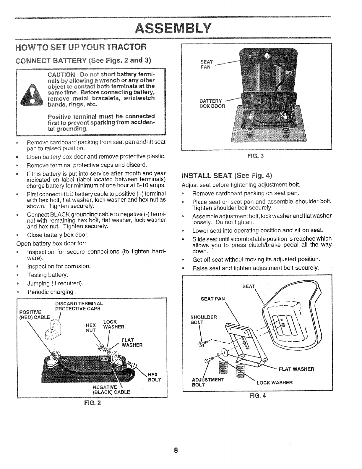
CONNECT BAKERY (See Figs. 2 and 3)
CAUTION: Do not short battery termio
hats by allowing a wrench or any other
obieet to contact both terminals at the
same time,, Before conneetin 9 battery,
remove meta_ bracelets, wristwatch
bands, rings, etco
Positive terminam must be connected
first to prevent sparking from acciden°
tat grounding°
o Remove cardboard packing from seat pan and tilt seat
pan to raised position.
o Open battery box door and remove protective ptastic.,
o Remove terminal protective caps and discard.
o if this battery is put into service after month and year
indicated on labe_ (label located between terminals)
charge battery for minimum of one hour at 6-10 amps.
First connect RED battery cable to positive (+) terminal
with hex bo_t,flat washer, lock washer and hex nut as
shown. Tighten securely.
o Connect BLACK grounding cable to negative (-) termi-
na! with remaining hex bolt, flat washer, lock washer
and hex nut. Tighten securely.
• Close battery box door.
Open battery box door for:
• Inspection for secure connections (to tighten hard-
ware).
, inspection for corrosion.
• Testing battery.
• Jumping (if required).
o Periodic charging.
D_SCARD TERMINAL
POSiTiVE
(RED) CABLE
PROTECTIVE CAPS
HEX WASHER
NUT
LOCK
FLAT
WASHER
SEAT
PAN
BATTERY
BOX DOOR
FiG. 3
INSTALL SEAT (See Fig. 4)
Adjust seat before tightening adjustment bolt.
• Remove cardboard packing on seat pan.
® Place seat on seat pan and assemble shoulder bolt.
Tighten shoulder bait securely.
o Assemble adjustment bolt, lock washer and flat washer
loosely. Do not tighten.
Lower seat into operating position and sit on seat.
• Slide seat until a comfortable position is reached which
allows you to press clutch/brake pedal all the way
down.
, Get off seat without moving its adjusted position.
Raise seat and tighten adjustment bolt securely.
SEAT
SEAT PAN
SHOULDER
BOLT
NEGATIVE
(BLACK) CABLE
FiG° 2
BOLT
FLAT WASHER
ADJUSTMENT
BOLT
LOCK WASHER
FJGo4
8

LY
INSTALL t\,IULCHER PLATE
(See Figs, 5 and 6)
- Install two Jatch hooks to mulcher pBate using screw,
washer, lock washer, and weid nut as shown.
NOTE: Pre-assemble weld nut to latch hook by inserting
weld nut from the top with hook pointing down°
- Tighten hardware securelyo
® Raise and hold deflector shield in upright position.
• Place front of mulcher plate over front of mower deck
opening and slide into place, as shown.
- Hook front latch into hole on front of mower deck.
- Hook rear latch into hole on back of mower deck.
guard when a,aching muiche, plate
TO CONVERT TO BAGGING OR
DISCHARGING
Simply remove mulcher plate and store in a safe place.
Your mower is now ready for discharging or installation of
optional grass catcher accessory.
NOTE: it is not necessary to change blades. The mulcher
blades are designed for discharging and bagging also.
LATCH
NOOK
WASHER
MULCHER
PLATE
NOOK POINTS
WELD NUT
FROM THE TOP
HOOK
WELD
NUT
FiG. 5
DEFLECTOR
SHIELD
LATCH
HOOKS
FiG. 6
9

...... ASSE LY
CHECKTmREPRESSURE
The tires on your tractor were ov_rinflat_tbry for
shipping purposes. Correct tire pressure is impQrtar}t for
best cutting performance. .....
Reduce tire pressure to PSi shown in "PROE_UCT
SPECIFICATIONS" on page 3 of this manual.
CHECK DECK LEVELNESS
For best cutting results, mower housing should be properly
_eveted. See "TO LEVEL MOWER HOUSING" in the
Sewice and Adjustments section of this manual.
CHECK FOR PROPER POSITION OF ALL
BELTS
See the figures that are shown for replacing motion and
mower blade drive belts in the Service and Adjustments
section of this manual. Verify that the belts are routed
correctly.
CHECK BRAKE SYSTEM
After you learn how to operate your tractor, check to see
that the brake is properly adjusted. See "TO ADJUST
BRAKE" in the Service and Adjustments section of this
manuai.
,/CHECKLIST
BEFORE YOU OPERATE AND ENJOY YOUR NEW
TRACTOR, WE WISH TOASSURE THAT YOU RECEIVE
THE BESTPERFORMANCEAND SATISFACTION FROM
THIS QUALITY PRODUCT.
PLEASE REVIEW THE FOLLOWING CHECKLIST:
¢" All assembly instructions have been completed.
7" No remaining toose parts in carton.
V" Battery' is properly prepared and charged. (Minimum
1 hour at 6 amps).
/ Seat is adjusted comfortably and tightened securely.
7 All tires are properly inflated. (For shipping purposes,
the tires were overinflated at the factory).
,/ Be sure mower deck is properly leveled side-to-side/
frontoto-rear for best cutting results. (Tires must be
properly inflated for leveling).
,/ Check mower and drive belts. Be sure they are routed
properly around pulleys and inside all belt keepers.
v" Check wiring. See that all connections are still secure
and wires are properly clamped.
WHILE LEARNING HOW TO USE YOUR TRACTOR, PAY
EXTRA ATTENT!ON TO THE FOLLOWING IMPORTANT
ITEMS:
,/ Engine oil is at proper level.
,/ Fuel tank is filled with fresh, clean, regular unleaded
gasoline.
,/ Become familiar with all controls - their location and
function. Operate them before you start the engine.
¢" Be sure brake system is in safe operating condition.
10

OPE 0
These symbots may appear on your tractor or in literature supplied with the product. Learn and understand their meaning.
BATTERY CAUTION OR REVERSE FORWARD FAST
WARNING
ENGINE ON ENGINE OFF OiL PRESSURE CLUTCH LIGHTS ON
FUEL CHOKE MOWER HEIGHT DIFFERENTIAL PARKING BRAKE UNLOCKED
LOCK LOCKED
OVER TEMP
L
SLOW
LIGHT
REVERSE IklI:::HTI3AI
MOWER LiFT
DANGER, KEEP HANDS AND FEET AWAY
ATTACHMENT
CLUTCH ENGAGED
HIGH
ATTACHMENT
CLUTCH DISENGAGED
11
LOW
PARKING BRAKE
IGNITION
HYDROSTATIC FREE WHEEL
(Hydro Models only)

}<NOW YOUR ....,.,......
READ THIS OWNER'S MANUAL AND SAFETY RULES BEFORE OPERATING YOUR TRACTOR
Compare the illustrations with your tractor to familiarize yourself with the locations of various controls and adjustments. Save
this manuat for future reference.
LIGHT
SWITCH
LIFT LEVER
PLUNGER
ATTACHMENT
LIFT. LEVER
I\t
MOWER DECK
HEIGHT ADJUSTMENT
POSITIONS
GEARSHIFT
LEVER
Our tractors conform to the safety standards of the American National Standards institute.
ATTACHMENT CLUTCH LEVER: Used to engage the
mower blades, or other attachments mounted to your
tractor.
LIGHT SWITCH: Turns the headlights on and off.
THROTTLE/CHOKE CONTROL: Used for starting and
controlling engine speed.
CLUTCH/BRAKE PEDAL: Used for declutching and brak-
ing the tractor and starting the engine.
PARKING BRAKE: Locks clutch/brake pedal into the
brake position.
PARKING
BRAKE
FIG. 7
GEARSHIFT LEVER: Selects the speed and direction of
tractor.
ATTACHMENT LIFT LEVER: Used to raise, lower, and
adjust the mower deck or other attachments mounted to
your tractor.
LiFT LEVER PLUNGER: Used to release attachment lift
lever when changing its position. 4
iGNITiON SWITCH: Used for starting and stopping the
engine.
AMMETER: indicates battery charging (+) or discharging
(-),
!2
E
vision safety mask over the spectacles or standard safety, gmasseso
HOW TO USE YOUR TRACTOR
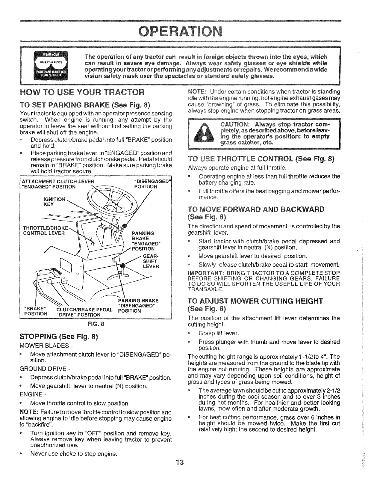
TO SET PARKING BRAKE (See Fig, 8}
Your tractor is equipped with an operator presence sensing
switch, When engine is running, any attempt by the
operator to leave the seat without first setting the parking
brake wil! shut off the engine.
• Depress clutch/brake pedal into fult "BRAKE" position
and hold.
• Place parking brake lever in "ENGAGED" position and
remain in "BRAKE" position. Make sure parking brake
wil_hold tractor secure.
ATTACHMENT CLUTCH LEVER
"ENGAGED" POSiTiON
_GNITtON
KEY
THROTTLE/CHOKE',
CONTROL LEVER
PARKING
BRAKE
"ENGAGED"
NOTE: Under certain conditions when tractor is standing
idle with the engine running, hot engine exhaust gases may
cause "browning '_of grass. To eliminate this possibility,
always stop engine when stopping tractor on grass areas.
pletely, as described above, before leav-
CAUTION: Always stop tractor corno
ing the operator's position; to empty
grass catcher, ere,
TO USE THRO_LE CONTROL (See Fig° 8)
Always operate engine at full throttle.
o Operating engine at tess than full throttle reduces the
battery charging rate.
o Fuji throttle offers the best bagging and mower perfor-
mance.
TO #OVE FORWARD AND BACKWARD
(See Fig, 8}
The direction and speed of movement is controlled by the
gearshift tever.
• Start tractor with clutch/brake pedal depressed and
gearshift lever in neutral (N) position.
, Move gearshift lever to desired position.
o Slowly release clutch/brake pedal to start movement.
_MPORTANT: BRING TRACTOR TO A COMPLETE STOP
BEFORE SHIFTING OR CHANGING GEARS. FAILURE
TO DO SO W_LL SHORTEN THE USEFUL LIFE OF YOUR
TRANSAXLEo
PARKING BRAKE
"BRAKE" CLUTCH/BRAKEPEDAL POSiTiON
POSiTiON "DRWE"POSIT!ON
FiG. 8
"DISENGAGED"
STOPPING (See Fig. 8)
MOWER BLADES -
o Move attachment clutch lever to "DISENGAGED" po-
sition.
GROUND DRIVE o
• Depress clutch/brake pedal into full "BRAKE" position.
• Move gearshift lever to neutral (N) position.
ENGINE =
• Move throttle control to slow position.
NOTE: Failure to move throttle control to slow position and
allowing engine to idle before stopping may cause engine
to "backfire".
• Turn ignition key to "OFF" position and remove key.
Always remove key when leaving tractor to prevent
unauthorized use.
Never use choke to stop engine.
TO ADJUST MOWER CUTTING HEIGHT
(See Fig. 8)
The position of the attachment lift lever determines the
cutting height.
, Grasp lift lever°
• Press plunger with thumb and move lever to desired
position.
The cutting height range is approximately 1-1/2 to 4". The
heights are measured from the ground to the blade tip with
the engine not running. These heights are approximate
and may vary depending upon soil conditions, height of
grass and types of grass being mowed.
The average lawn should be cut to approximately 2-1/2
inches during the cool season and to over 3 inches
during hot months. For healthier and better looking
lawns, mow often and after moderate growth.
, For best cutting performance, grass over 6 inches in
height should be mowed twice. Make the first cut
relatively high; the second to desired height.
is
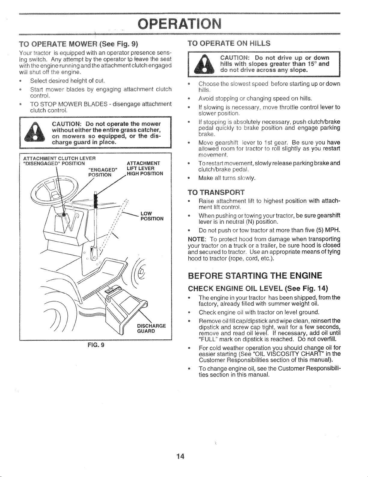
TO OPERATE MOWER(See Fig, 9)
Your tractor is equipped with an operator presence sens-
ing switch. Any attempt by the operator tp leave the seat
with the engine running and the attachment clutch engaged
will shut off the engine.
o Select desired height of cut.
o Sta_t mower blades by engaging a_achment ciutch
control
TO STOP MOWER BLADES odisengage attachment
clutch control.
TO OPERATE ON H_LLS
Choose" _c_ --_
hills°
Avoid stopping or changing speed on hilts.
, If slowing is necessary, move throttle control lever to
_hes ow_,_ speed b_,ore starting up or down
F CAUTION: Do not operate the mower
without either the entire grass catcher,
_ _ on mowers so equipped, or the dis-
charge guard in pla.Ceo
ATTACHMENT CLUTCH LEVER
"DISENGAGED"' POSIT_ON
"ENGAGED"
POSiTiON
ATTACHMENT
LiFT LEVER
HiGH POSITION
rt
LOW
POSiTiON
////z
D_SCHARGE
GUARD
FiG. 9
ff stopping is absolutely necessary, push clutch/brake
pedal quickly to brake position and engage parking
brake
Move gearshift lever to 1st 9ear. Be sure you have
allowed room for tractor to roll s%hfly as you restart
movement.
To restart movement, slowly release parking brake and
clutch/brake pedat.
Make al! turns slowly.
TO TRANSPORT
Raise attachment lift to highest position with attach-
ment lift control
When pushing or towing your tractor, be sure gearshift
lever is in neutral (N) position.
o Do not push or tow tractor at more than five (5) MPH.
NOTE: To protect hood from damage when transporting
your tractor on a truck or a trailer, be sure hood is closed
and secured to tractor. Use an appropriate means of tying
hood to tractor (rope, cord, etc,).
BEFORE STARTING THE ENGINE
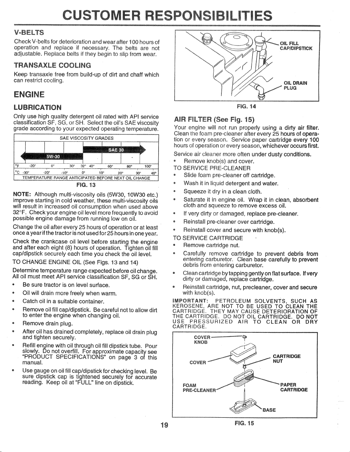
CHECK ENG!NE OiL LEVEL (See Fig. !4)
® The engine in your tractor has been shipped, from the
factory, already tilled with summer weight oil.
o Check engine oil with tractor on level ground.
® Remove oil fill cap/dipstick and wipe clean, reinsert the
dipstick and screw cap tight, wait for a few seconds,
remove and read oil level, if necessary, add oil until
"FULL" mark on dipstick is reached. Do not overfill.
, For cold weather operation you should change oil for
easier starting (See "OIL VISCOSITY CHART" in the
Customer Responsibilities section of this manual).
To change engine oil, see the Customer Responsibili-
ties section in this manual.
14
CUSTOMER
ESPONSIB
ES
TRACTOR
Always observe safety rules when performing any mainte°
nar_ceo
BRAKE OPERATION
if tractor requires more than six (6) feet stopping distance
at high speed in highest gear, then brake must be adjusted.
(See "TO ADJUST BRAKE" in the Service and Adjust-
ments section of this manual)o
TIRES
o Maintain proper air pressure in ali tires (See "PROD°
UCT SPEC!FICATIONS" on page 3 of this manual).
o Keep tires free of gasoline, oil, or insect controt cherni-
cats which can harm rubber.,
o Avoid stumps, stones, deep ruts, sharp objects and
other hazards that may cause tire damage.
NOTE: To seal tire punctures and prevent flat tires due to
slow leaks, tire sealant may be purchased from your local
parts deater. Tire sealant also prevents tire dry rot and
corrosion.
BLADE CARE
For best results mower blades must be kept sharp. Re-
place bent or damaged blades.
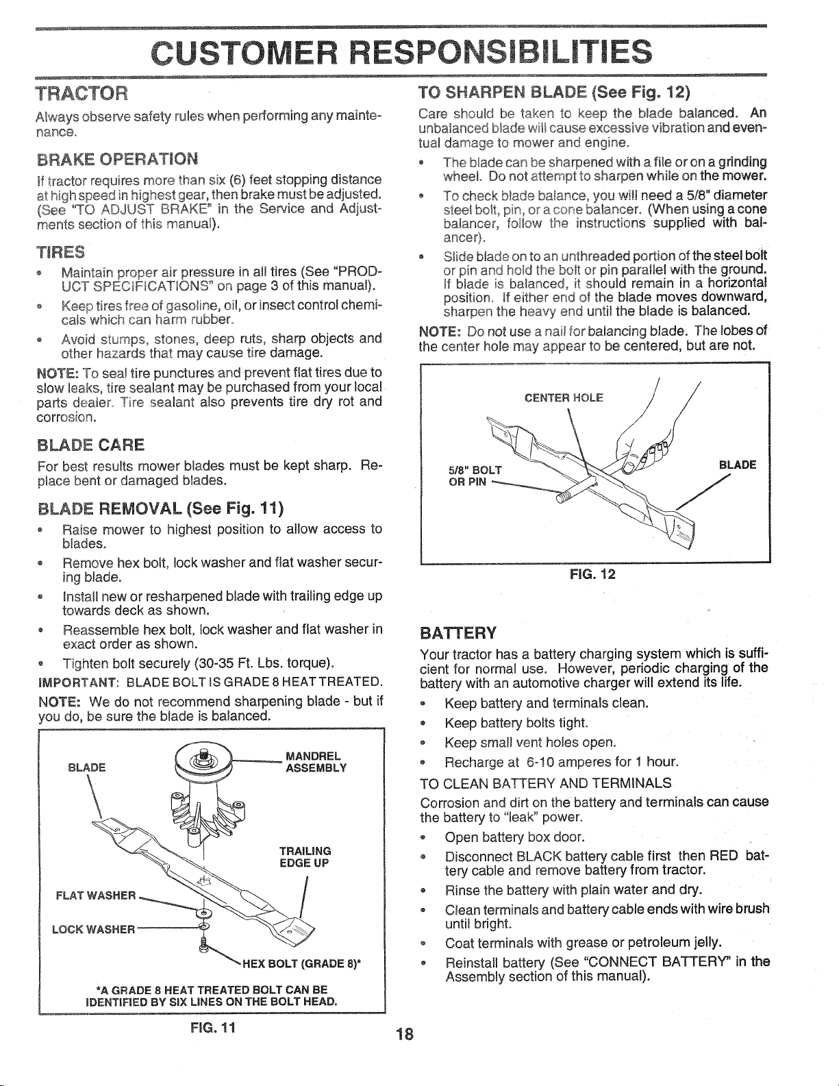
TO SHARPEN BLADE (See Fig. 12)
Care shouk_ be taken to keep the blade balanced. An
unbalanced blade will cause excessive vibration and even-
tuat damage to mower and engine°
The blade can be sharpened with afile or on a grinding
wheel Do not attempt to sharpen while on the mower.
-- To check blade balance, you wit! need a 5/8" diameter
stee_bolt, pin.°or a cone baiancer. (When using a cone
balancer, fotlow the instructions supplied with baF
o Stide blade on to an unthreaded portion of the steel b0Jt
or pin and ho_dthe bolt or pin paraJtel with the ground.
If blade is balanced, it should remain in a horizontal
position. If either end of the blade moves downward,
sharpen the heavy end until the btade is balanced.
NOTE: Donot use a nail for balancing blade. The lobes of
the center hole may appear to be centered, but are not.
CENTER HOLE
BLADE REMOVAL (See Fig. 11)
o Raise mower to highest position to allow access to
blades.
Remove hex bolt, lock washer and flat washer secur-
ing blade.
Install new or resharpened blade with trailing edge up
towards deck as shown.
Reassemble hex bolt, lock washer and flat washer in
exact order as shown.
-_ Tighten bolt securely (30-35 Ft. Lbs. torque).
iMPORTANT: BLADE BOLT IS GRADE 8 HEATTREATED.
NOTE: We do not recommend sharpening blade - but if
4ou do, be sure the blade is balanced.
TRAiLiNG
EDGE UP
LOCK WASHER
FLAT WASHER __
_" HEX BOLT (GRADE 8)*
*A GRADE 8 HEAT TREATED BOLT CAN BE
IDENTIFIED BY SIX LINES ON THE BOLT HEAD.
FIG. 12
BATTERY
Your tractor has a battery charging system which is suffi-
cient for normal use. However, periodic charging of the
batter,! with an automotive charger will extend its life.
* Keep battery and terminals clean.
Keep battery bolts tight.
Keep small vent holes open.
o Recharge at 6-10 amperes for 1 hour.
TO CLEAN BATTERY AND TERMINALS
Corrosion and dirt on the battery and terminals can cause
the battery to "leak" power.
Open battery box door.
Disconnect BLACK battery cable first then RED bat-
tery cable and remove battery from tractor.
Rinse the battery with plain water and dry.
, Ciean terminals and battery cable ends with wire brush
until bright.
o Coat terminals with grease or petroleum jelly.
Reinstall battery (See "CONNECT BATTERY" in the
Assembly section of this manual).
FiG. 11 18
VoBELTS
Check V-beJts for deterioration and wear after 100 hours of
operation and replace if necessary. The belts are not
adjustable. Replace belts if they begin to s_ipfrom wear°
TRANSAXLE OOOUNG
Keep transaxte free from build-up of dirt and chaff which
can restrict cooling.
ENGINE
ES ES
OiL F|LL
CAP/DIPSTICK
OiL DRAIN
PLUG
LUBRICATION
Only use high quality detergent oil rated with API service
classification SF, SG, or SHe Select the oil's SAE viscosity
grade according to your expected operating temperature.
SAE VISCOSITY GRADES
T
oF _20o 0,, 30° 32 ° 40 ° 60_ 80 °
_C -30 ° -20 ° d0 ° 0° iO ° ;0 o
TEMPERATURE RANGE ANTICIPATED BEFORE NEXT OiL CHANGE
FiG, 13
NOTE: Although multi-viscosity oils (5W30, 10W30 etc.)
improve starting in cold weather, these multi-viscosity oils
will result in increased oil consumption when used above
32°F. Check your engine oit level more frequently to avoid
possible engine damage from running low on oil.
Change the oil after every 25 hours of operation or at least
once a year ifthe tractor is not used for 25 hours in one year.
Check the crankcase oil level before starting the engine
and after each eight (8) hours of operation. Tighten oil fill
cap/dipstick securely each time you check the oil level
TO CHANGE ENGINE OIL (See Figs. 13 and 14)
Determine temperature range expected before oil change.
All off must meet APJ service classification SF, e_'v"or SH.
, Be sure tractor is on level surface.
o
Oil will drain more freely when warm.
®
Catch oil in a suitable container.
o
Remove oil fill cap/dipstick. Be careful not to aitow dirt
to enter the engine when changing oil.
o
Remove drain plug.
o
After oil has drained completely, replace oil drain plug
and tighten securely.
Refil! engine with oil through oil fil! dipstick tube. Pour
slowly. Do not overfill. For approximate capacity see
"PRODUCT SPECiFICATiONS" on page 3 of this
manual.
Use gauge on oil fill cap/dipstick for checking level. Be
sure dipstick cap is tightened securely for accurate
reading. Keep oil at "FULL" line on dipstick.
FiG. 14
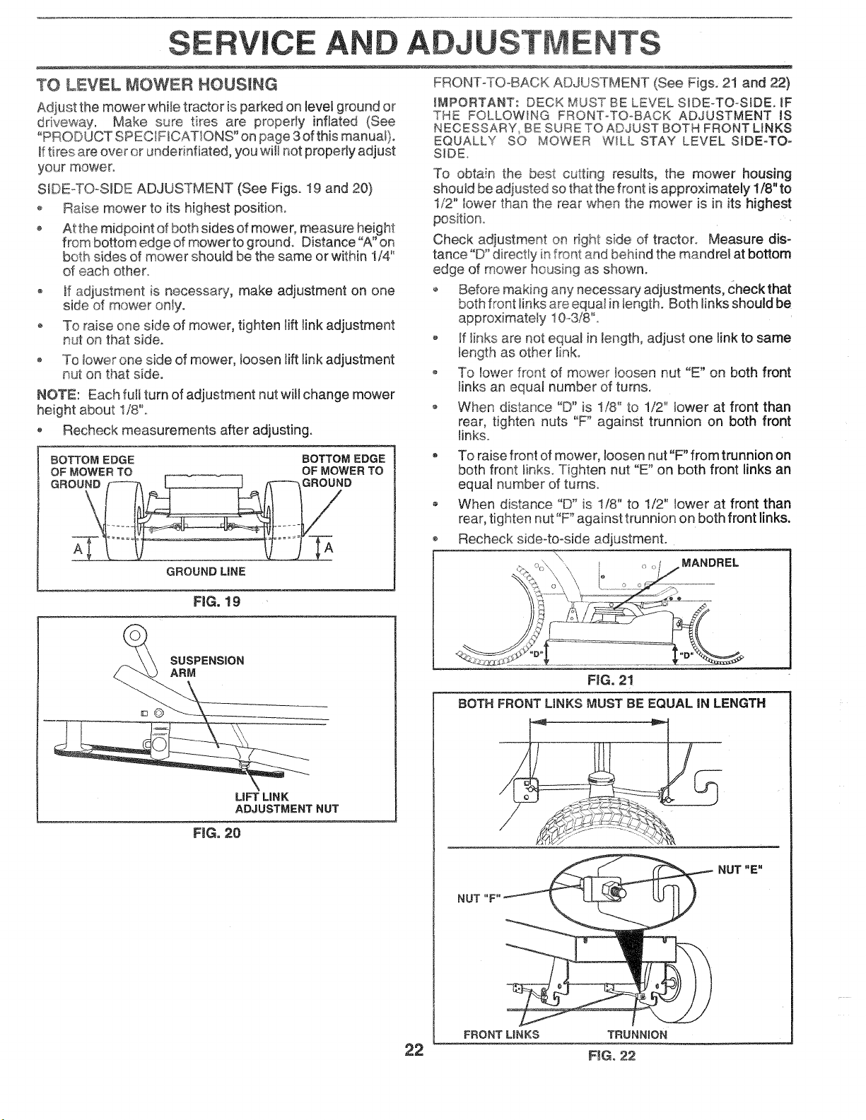
AIR FmLTER (See Fig. 15)
Your engine wi!l not run properly using a dirty air filter.
Clean the foam preocleaner after every 25 hours of opera-
tion or every season. Service paper cartridge every 100
hours of operation or every season, whichever occurs first.
Service air cleaner more often under dusty conditions.
, Remove knob(s) and cover.
TO SERVICE PRE-CLEANER
Slide foam preocteaner off cartridge.
, Wash it in liquid detergent and water.
Squeeze it dry in a clean cloth.
o Saturate it in engine oil Wrap it in clean, absorbent
cloth and squeeze to remove excess oi!.
o tf very dirty or damaged, replace pre=cleaner.
o Reinstall pre-cieaner over cartridge.
o Reinstall cover and secure with knob(s).
TO SERVICE CARTRIDGE
* Remove cartridge nut.
o Carefully remove cartridge to prevent debris from
entering carburetor. Clean base carefully to prevent
debris from entering carburetor.
Clean cartridge bytapping gently on flat surface, ff very
dirty or damaged, replace cartridge.
Reinstall cartridge, nut, precleaner, cover and secure
with knob(s).
iMPORTANT: PETROLEUM SOLVENTS, SUCH AS
KEROSENE, ARE NOT TO BE USED TO CLEAN THE
CARTRIDGE. THEY MAY CAUSE DETERiORATiON OF
THECARTRtDGEo DO NOT OIL CARTRtDGE. DO NOT
USE PRESSURIZED AfR TO CLEAN OR DRY
CARTRIDGEo
COVER .....
KNOB
CARTRIDGE
COVER
FOAM
PREoCLEAN_ ' CARTRIDGE
NUT
_BABE
19 FiG. 15

CUSTOME PO IL!T!ES
CLEAN A_R SCREEN (See Fig, 16}
Air screen must be kept free of dirt and chaff to prevent
engine damage from overheating. Clean with a wire brush
or compressed air to remove dirt and stubborn dried gum
fibers°
ENGINE COOMNG FINS (See Fig. 16)
Remove any dust, dirt. or oi! from engine coo!ing fins to
prevent engine damage from overheating.
o Remove screws from blower housing and lift housing
and dipstick tube assembly off engine.
,_ Cover oi! fill opening to prevent entry of dirL
o Use compressed ar or stiff bristie brush to thoroughly
clean engine cooling fins.
o To reassemble, reverse above procedure.
BLOWER HOUStNG
A_R SCREEN
OiL FiLL
TUBE
ASSEMBLY
ENGINE COOMNG RNS
SCREWS
SPARK
PLUG
IN-LiNE FUEL RLTER (See Fig, 17)
The fuel filter should be replaced once each season, fffuel
filter becomes clogged, obstructing fuel flow to carburetor,
replacement is required°
o With engine cool, remove filter and plug fuel line
sections.
o Ptace new fuel filter in position in fuel line with arrow
o Be sure there are no fuet line leaks and clamps are
properly positioned°
Immediately wipe up any spilled gasoline.
FIG, 17
CLEANING
Clean engine, battery, seat, finish, etc. of all foreign
matter.
Keep finished sudaces and wheels free of al! gasoline,
oil, etc.
• Protect painted surfaces with automotive type wax.
We do not recommend using a garden hose to clean your
tractor unless the electrical system, muffler, air filter and
carburetor are covered to keep water out. Waterin engine
can result in a shortened engine life,
FiG. !6
MUFFLER
Inspect and replace corroded muffler and spark arrester (if
equipped) as it could create a fire hazard and/or damage.
SPARK PLUGS
Replace spark plugs at the beginning of each mowing
season or after every 100 hours of operation, whichever
occurs first. Spark plug type and gap setting are shown in
"PRODUCT SPECIFICATIONS" on page 3 of this manual.
20

EFIViCE A ADJ ENTS
CAUTION: gEFORE PERFORMING ANY SERVICE OR ADJUSTMENTS:
® Depress clutc_rbrake pedaJ fully and set parking brake,
* Place gearshift _ever in neutra| (N) position,
* PWaceattachment clutch in "DISENGAGED" position,
* Turn ignition key "OFF" and remove key=
, Make sure the blades and aU moving parts have completely stopped,
-= Disconnect spark plug wire from spark piug and piace wire where it cannot come _ncontact with
plug°
TO REMOVE MOWER (See Fig. 18)
Mower will be easierto remove from the right side of tractor.
* Place attachment clutch in "DISENGAGED" position.
* Move attachment lift lever forward to lower mower to its
lowest position,
* Roll belt off engine pulley.
, Disconnect clutch rod from clutch lever by removing
retainer spring.
, Disconnect anti-sway bar from chassis bracket by
removing retainer spring,
* Disconnect suspension arms from rear deck brackets
by removing retainer springs,
® Disconnect front links from deck by removing retainer
springs.
, Raise lift lever to raise suspension arms. Slide mower
out from under tractor.
iMPORTANT: iFAN ATTACHMENT OTHER THAN THE
MOWER iS TO BE MOUNTED TO THE TRACTOR,
REMOVE THE FRONT LINKS.
TO INSTALL MOWER (See Fig. 18)
- Raise attachment lift lever to its highest position.
• Slide mower undertractorwith discharge guardto right
side of tractor.
• Lower lift lever to its lowest position,
, Install mower in reverse order of removal instructions.
CLUTCH LEVER
CLUTCH
SUSPENSION ENGINE
ARMS PULLEY
SPRINGS
/
RETAINER
SPRING
ANTIoSWAYBAR
RETAINER
SPRINGS
(BOTH SIDES)
FIG. 18
SLOES)!
21
SERVICE AN A
TO LEVEL MOWER HOUSING
Adiust the mower while tractor is parked on level ground or
Make sure tires are property inflated (See
"PRODUCT SPECIFICATIONS" on page 3 ofthis manuat).
tftires are over or underinfiated, you will not properly adjust
your mower.
SDEoTO-SIDE ADJUSTMENT (See Figs° I9 and 20)
o Raise mower to its highest positiono
o At the midpoint of both sides of mower, measure height
from bottom edge of mower to ground. Distance "A" on
both sides of mower should be the same or within 1/4"
of each other.
o Jfadjustment is necessary', make adjustment on one
side of mower onty.
To raise one side of mower, tighten lift link adjustment
nut on that side.
To lower one side of mower, loosen lift link adjustment
_u_ Ot_that side.
NOTE: Each fult turn of adjustment nut will change mower
height about 1/8"o
Recheck measurements after adjusting.
BOTTOM EDGE BOTTOM EDGE
OF MOWER TO OF MOWER TO
GROUND f_h [ ]/T---_,GROUND
GROUND MNE
FRONT-TO-BACK ADJUSTMENT (See Figs. 21 and 22)
_MPORTANT: DECK MUST BE LEVEL SIDEoTO-SIDE. 1F
THE FOLLOWING FRONToTO_BACK ADJUSTMENT IS
NECESSARY_ BE SURE TO ADJUST BOTH FRONT LINKS
EQUALLY SO MOWER WILL STAY LEVEL SIDE-TO-
SIDE.
To obtain the best cutting results, the mower housing
should be adjusted so that the front is approximately 1/8" to
1/2" lower than the rear when the mower is in its ,_<"_'""*,,u,,_o,
Check adjustment on right side of tractor Measure dis-
tance "D" directly in front and behind the mandrel at bottom
edge of mower ho_Jsing as shown°
o Before making any necessary adjustments, Check that
both front links are equaI in length. Both links should be
approximately 10o3/8"o
o If Iinks are not equal in tength, adjust one tink to same
length as other link.
o _r_,,,, ,_owerfront _,f_,,,,_w_,m_,__ !oosen nut "_"_on both front.
links an equat number of turns.
o When distance "D" is !/8" to 1/2" lower at front than
rear, tighten nuts "F" against trunnion on both front
links.
To raise front of mower, loosen nut"F" from trunnion on
both front links. Tighten nut "E" on both front links an
equal number of turns.
When distance "D" is 1/8" to t/2" lower at front than
rear, tighten nut "F" against trunnion on both front links.
Recheck side4o-side adjustment.
\\
I MANDREL
[]©
FiG. 19
SUSPENSION
ARM
FIG. 20
FIG. 21
BOTH FRONT LINKS MUST BE EQUAL iN LENGTH
LiFT LiNK
ADJUSTMENT NUT
NUT "E"
NUT "F"
FRONT UNKS TRUNNION
22 F_Go22
 Loading...