

Craftsman 917258492 Owner’s Manual

S A/k S
®
Caution:
Read and follow
all Safety Rules
and instructions
Before Operating
This Equipment
18,0 HP TWUNCYLmNDER
ELECTRIC START
42" MOWER DECK
5 SPEED TRANSA×LE
LAWN TRACTOR
, AssembUy
oOperation
Customer Responsibilities
oServBceand Adjustment
, Repair Parts
Sears, Roebuck and Co., Chicago, IL 60684 U.S.A.

Safe Operation Practices for Ride-On Mowers
SAFETY RULES
IMPORTANT: THIS CUTTING MACHINE IS CAPABLE OFAM PUTATING HANDS AND FEETAND THROWING OBJECTS,
FAILURE TO OBSERVE THE FOLLOWING SAFETY INSTRUCTIONS COULD RESULT IN SERIOUS INJURY OR DEATH,
GENERAL OPERATION
Road, understand, and follow all instructions in the manual
and on the machine before starting.
Only allow respeesible adults, who are familiar with the
instructions, to operate the machine.
Clear the area of eb ects such as rocks, toys, wire, etc,
which could be picked up and thrown by the bade.
Be sure the area is etearofother people before mowing Stop
machine if anyone enters the area.
Never carry passengers
Do not mow in reverse unless absolutely necassary_ Always
look down and behind before and while backing.
Be aware of the mower discharge direction and do not point
it at anyone. Do not operate the mower without either the
entire grass catcher or the guard in place.
Slow down before turning
Never leave a running machine unattended. Always turn off
blades, set parking brake, stop engine, and remove keys
before dismounting.
Turn off blades when not mowing_
Stop engine before removing grass catcher or unclogging
chute
Mow only in daylight or good artificial light
Do not operate the machine while under the influence of
alcohol or drugs
Watch for traffic when operating near or crossing roadways
Use extra care when loading or unloading the machine into
a trailer or truck
II. SLOPE OPERATION
Slopes are a major factor related to Ioss-of-control and tipover
accidents, which can result in severe injury or death. Atl slopes
require extra caution. If you cannot back up the slope or if you feel
uneasy ee it, do not mow it.
DO:
Mow up and down slopes, not across_
Remove obstacles such as rocks, tree limbs, etc.
Watch for holes, ruts, or bumps. Uneven terrain could
overturn the machine Tall grass can hide obstacles.
Use slow speed_ Choose a low gear so that you will not have
to stop or shift white on the slope.
Follow the manufacturer's recommendations for wheel
weights or counterweights to improve stability.
Use extra care with grass catchers or other attachments
These can change the stability of the machine
Keep all movement on the slopes slowand gradual Do not
make sudden changes in speed or direction
Avoid starting or stopping ee a slope. If tires lose traction,
disengage the blades arrd proceed slowly straight down the
slope
DO NOT:
Do not turn on slopes unless necessary, and then, turn slowly
and gradually downhill, if possib{e_
Do not mow near drop-errs, ditches, or embankments. The
mower could suddenly turn over if a wheel is over the edge
of a cliff or ditch, or if an edge caves in_
Do not mow on wet grass. Reduced traction could cause
sliding
Do not tryto stabilize the machine by putting your foot on the
ground_
Do not use grass catcher on steep slopes
III, CHILDREN
Tragic accidents can occur if the operator is not alert to the
presence of chitdren Children are often attracted to the machine
and the mowing activity. Neverassume that children will remain
where you last saw them
Keep children out of the mowing area and under the watchful
care of another responsible adult
Be alert and turn machine off if children enter the area
Before and when backing, look behind and down for small
children_
Never carry children. They may fall off and be seriously
njured or nterfere with safe mach ne operation.
Never allow children to operate the machiae_
Use extra care when approaching blind corners, shrubs,
trees, or other objects that may obscure vision.
IV. SERVICE
Use extra care in handling gasoline and other fuels. They are
flammable and vapors are explosive
Use only an approved container
Never remove gas cap or add fuel with the engine
running Allow engine to cool before refueling. Do not
smoke
Never refuel the machine indoors.
Never store the machine or fuel container inside where
there is an open flame, such as a water heater.
Never run a machine inside a closed area.
Keep nuts and bolts, especially blade attachment bolts, tight
and keep equipment in good condition.
Never tamper with safety devices. Check their proper
operation regularly.
Keep machine free of grass, leaves, or other debris build-up.
Clean oil or fuel spillage. Allow machine to cool before
storing_
Stop and inspect the equipment if you strike an object.
Repair, if necessary, before restarting,
Never make adjustments or repairs with the engine running.
Grass catcher components are subject to wear, damage, and
deterioration, which could expcae moving parts or allow
objects to be thrown. Frequently check components and
replace with manufacturer's recommended parts, when nec-
essary
Mower blades are sharp and can cuL Wrap the blade(s) or'
wear gloves, and use extra caution when servicing them.
Check brake operation frequently. Adjust and service as
required.
Look for this symbol to point out Impor-
tant safety precautions. It means
CAUTION!!f BECOME ALERT!!! YOUR
SAFETY IS INVOLVED.
CAUTION: Always disconnect spark
plug wire and place wire where It cannot
contact spark plug In order to prevent
accidental starting when setting up,
transporting, adjusting or making
repairs.
2

CONGRATULATIONS onyour purchase of a Sears
tractor, It has been designed, engineered and manufac-
tured to give you the best possible dependability and
performance,
Should you experience any problem you cannot easily
remedy please contact your nearest Sears Service
Center/Department We have competent, we -tra ned
technicians and the proper tools to service or repair this
unit.
Please read and retain this manual The instructions will
enable you to assemble and maintain your unit properly_
Always observe the "SAFETY RULES"
MODEL
NUMBER 917_258492
SERIAL
_IUMBER
DATE OF PURCHASE
THE MODEL AND SERIAL NUMBERS WILL BE FOUND
ON A PLATE UNDER THE SEAT,
YOU SHOULD RECORD BOTH SERIAL NUMBER AND
DATE OF PURCHASE AND KEEP IN A SAFE PLACE
FOR FUTURE REFERENCE
MAINTENANCE AGREEMENT
A Sears maintenance agreement is available on this prod-
uct. Contact your nearest Sears store for details.
CUSTOMER RESPONSiBiLiTIES
o Read and observe the safety rule&
o Followa regular schedule in maintaining, caring for and
using your unit.
o Follow the instructions under "Customer Responsibili-
ties" and "Storage" sections of this owner's manual,
PRODUCT SPEClFlCATBONS
HORSEPOWER: l&0
GASOLINE CAPACITY: &5 GALLONS
UNLEADED REGULAR
OIL (3..0PINTS): SAE 30 (above 32° F)
SPARK PLUG (GAP.030 IN.): CHAMPION RJ-19LM
VALVE CLEARANCE: INTAKE _004- 006 IN.
GROUND SPEED: FORWARD
TIRE PRESSURE: FRONT: 14 PSI
CHARGING SYSTEM:
BLADE BOLTTORQUE: 30-35 FT. LBS,
WARNING; This unit is equipped with an internal combus-
tion engine and should not be used on or near any unim-
proved forest-covered brush-covered or grass-covered
land unless the engineZs exhaust system is equipped with
a spark arrester meeting applicable local or state laws (if
any), If a spark arrester Is used it should be maintainea In
effective work ng order by the operator,
in the state of California the above is required bv law
(.Section 4442 of the California Public Resources (_ode),
Other states may have similar laws, Federal laws apply on
federal lands,, A spark arrester for the muffler is available
through your nearest Sears Authorized Service Center
(See REPAIR PARTS section of this manual)
SAE 5W-30 (below32° F)
STD361458
EXHAUST 007- .009 IN_
1st .77 MPH
2nd 1.46 MPH
3rd &41 MPH
4th 4,34 MPH
5th 557 MPH
REVERSE: 1.07 MPH
REAR: 10 PSI
5 AMPS HEADLIGHT
3 AMPS BATTERY
LIMITED TWO YEAR WARRANTY ON ELECTRIC START RiDiNG EQUIPMENT
For two (2) years from the date of purchase, if this riding equipment is maintained, lubricated and tuned up according to the
instructionsin the owner's manual, Sears will repair or replace,free of charge, any parts found to be defective in material or
workmanship.
This Warranty doesnot cover:
• Expendable items which become worn duringnormal use, suchasblades, sparkplugs, air cleaners and belts.
• Tire replacement or repair causedby puncturesfrom outsideobjects,such as nails,thorns, stumps, or glass.
Repairs necessary because of operatorabuse, negligence,improperstorage or accidentor the failureto maintain the
equipment according to the instructionscontained in the owner's manual.
• Riding equipment used for commercial or rentalpurposes..
UMiTED 90 DAY WARRANTY ON BATTERY
For90 days from date of purchase,ifany battery includedwiththis riding equipmentproves defective in material or workmanship
and our testing determinesthe battery will not holda charge,Searswill replacethe battery at no charge.
WARRANTY SERVICE IS AVAILABLE BY RETURNING THE RIDING EQUIPMENT TO THE NEAREST SEARS SERVICE
CENTER/DEPARTMENT IN THEUNITED STATES.
This Warranty gives you specific legal rights,andyou may also haveother rightswhich may vary from stateto state
SEARS, ROEBUCKAND CO., D/731CR-W,SEARSTOWER, CHICAGO, ILLINOIS 60684
3

TABLE OF CONTENTS
SAFETY RULES ............................................................ 2
PRODUCT SPECIFICATIONS ....................................... 3
CUSTOMER RESPONSIBILITIES ..................... 3, 14-17
WARRANTY ................................................................... 3
TABLE OF CONTENTS ................................................. 4
INDEX ............................................................................. 4
TRACTOR ACCESSORIES ........................................... 5
ASSEMBLY ................................................................ 7-9
MNDEX
A
Accessories ................................................ 5
Adjustments:
Brake ......................................................20
Carburetor. ..........................................23
Gauge Wheels ........................................9
Mower
Front-To-Back ........................_. 19
Side-To-Side ..................................18
Throttle Control Cable .....................22
Air Filter, Engine ..................................... 16
Air Screen, Engine .......................................16
Assembly ...................................................7-9
B
Battery:
Charging ..............................................8
Cleaning ........................................ 16
installation ................................................9
Levels .............................................8,16
Preparation ...........................................8
StaRing with Weal( Battery ............21
Storage ...................................................24
Terminals .........................................16
Bolt:
Motion Drive
Remova!/Replacement ........... 20
Mower Blade Drive
RemovaVReplacement ................20
Blade:
Sharpening ........................................15
Replacement ................................... 15
Brake Adjustment ................................. 20
C
Carburetor Adjustment ......................... 23
Controls, Tractor ......................................10
Customer Responsibilities ............. 15-17
Engine:
Ail Filter ....................................... 16
Air Filter Foam Pre-Cleaner ._..16
Air Screen, Engine .................... 16
Battery .......................................... 15
Cooling Fins, Engine ............... 17
Engine Oil ............................................16
Fuel Filter ................................. 17
Spark Plugs ....................................17
Tractor:
Blade ....................................... 15
Lubrication Chad ........................ 14
Maintenance Schedule ..............14
Tire Care ........................... 8,15,21
Cutting Height, Mower ............................11
Electrical:
Interlocks and Relays .......................22
Schematic ..........................................27
Wiring Diagram ................................28
Engine:
Air Filter. ...............................................16
Air Filter Foam Pre-Cleaner .........16
Air Screen .........................................16
Cooling Fins, Engiae ........................17
Oil Change .................................... 16
Oil Level .................................... 12,16
Oil Type ................................................16
Preparation .................................... 12
Repair Pads ............................ 41-46
Starling ............................................ 13
Storage ...............................................24
Filter:
Air Filter .............................................16
Air Filter Foam Pre-Cleaner ........ 16
Fuel ...................................................17
Fuel:
Type ...................................................12
Storage ........................................... 24
Fuse ......................................................... 22
Gauge Wheel Installation ....................... 9
Hood Removal/installation ................... 22
Leveling Mower Deck .................... 18-19
Lubrication:
Char ............................................ 14
Maintenance Schedule ......................... 14
Mower:
Adjustment, Front-to-Back .............19
Adjustment, Side-to-Side .............. 18
Adjustment, Gauge Wheel ..............9
Blade Sharpening .......................... 15
Blade Replacement ..................... 15
Cutting Height ...................................11
Installation ..................................... 18
Operation ........................................ 12
Removal ....................................... 18
Mowing Tips ......................................... 13
Muffler ...........................................................17
Spark Arrester .......................... 3,32
OPERATION ........................................................... 10-13
MAINTENANCE SCHEDULE ...................................... 14
SERVICE AND ADJUSTMENTS ............................ 18-23
STORAGE .................................................................... 24
TROUBLESHOOTING ............................................ 25-26
REPAIR PARTS - TRACTOR ................................. 28-40
REPAIR PARTS - ENGINE ..................................... 41-46
PARTS ORDERING/SERVICE ................... BACK PAGE
E
Oil:
Cold Weather Conditions ....... 12,16
Engine ........................................... 16
Storage ......................................... 24
Operation ..............;............................ 10-13
Operating Mower ................................ 12
Options:
Accessories ................................... 5
Spark Arrester ........................... 3,32
o
P
Parking Brake ................................. 10-11
Parts Bag .............................................. 6
Parts, Raplacement/Repair ........... 28-46
Product Specifications ............................ 3
R
F
G
H
L
M
RepairParts ......................................28-46
S
Safety Rules .............................................2
Seat .........................................................8
Service and Adjustmerrts..................18-23
Carburetor, ...................................23
Fuse .............................................22
Hood Removal/Installation .......... 22
Motion Drive Belt
RemovaVReplacement...........20
Mower Blade Drive Belt
RemovaVReplacement...........20
Mower Adjustment
Front- to-Back ......................... 19
Side-to-Side............................ 18
Mower Removal .......................... 18
Tire Care ............................ 8,15,21
Slope Guide Sheet ............................. 47
Spark Plugs ........................................ 17
Specifications ........................................3
Stading the Engine........................ 12-13
Steering Wheel ................................ 7,21
Stoppingthe Tractor, .......................... 11
Storage ............................................... 24
T
Throttle Control Cable
Adjustment .....................................22
Tires....................................................8,15,21
Trouble Shooting Chart..................25-26
Transaxle:
Repair Pads........................... 38-39
W
Warranty ............................................... 3
Wiring Diagram .....................................28
Wiring Schematic.................................29
4

ACCESSORRES ATTACHMENTS
These accessories andattachments wereavailable when the unit was purchased. They are also available at most Sears retailoutlets,
catalog and service centers. Most Sears stores can order these items for you whenyou providethe model number of your tractor_
ENGINE
SPARKPLUG MUFFLER AIRFILTER GASCAN ENGINEOIL STABILIZER
MAINTENANCE
BLADES BELTS
PERFORMANCE
Sears offers a wide variety of attachmentsthat fit yourvehicle_ Many of these are listed belowwith brief explanations of how they can
helpyou,.This listwas current atthe time ofpublication;however,itmaychange infutureyears- moreattachments maybe added, changes
may be made in these attachments, or somemay no longer be available or fityour model. Contact your nearest Sears store for the
accessories and attachments that are available for your unit.
Most of these attachments do not require additional hitches or conversion kits (those that do are indicated) and are designed for easy
attaching and detaching
PERMANEX BAGGER lets you collect grass clippings and
leaves for a healthier, neater looking lawn. Two Permanex
containers hold 3B-gallon plastic bags.
LAWN SWEEPERS let you coltect grass clippings and leaves.
LAWN VAOS forpowerful collection of heavygrassclippings and
leaves. Wand attachment to pick up debris in hard-to-reach
places.
CARTS make hauling easy. Variety of sizes available.
ROLLER for smoother lawn surface. 36-inch wide, 18-inch
diameterwater.tight drum holdsupto 39Bibs. ofweighL Rounded
edges prevent harm to tuff. Adjustable scraper automatically
cleans drum.
SPREADER/SEEDERS make seeding, fertilizing, and weed
killing easy. Broadcast spreaders are also useful for granular de-
icers and sand.
CORING AERATOR takes small plugs out of soil to allow mois-
ture and nutrients to reach grass roots. 36-inch swath. 24
hardened steel coring tips. 150 lb. capacity weight tray_
AERATOR promotes deep root growth for a healthy lawn. Ta-
pered 2_5-inchsteel spikes mounted on 10_inchdiameter discs
puncture holes in soil at close intervalsto let moisture soak ino
Steel weight tray for increased penetration,
MULCHRAKE/DETHATCHER loosens soilandflips thatch and
mattedleavesto lawnsurface for easypickup. Twenty springtine
teeth_Usefultopreparebaraareasforseeding Availableforfront
or rear mounting.
SPRAYERS use 12-volt DC electric motor that connects to the
tractor battery or other 12-volt source. Includes booms for
automatic spraying when pulling, and hand held wand for spot
spraying_ Wand has adjustable spray pattern_ For applying
herbicides, insecticides, fungicides, andliquid fertilizers.
SNOW BLADE for snow removal only_ 14-inch high, 42-inch
wide blade clears 38-inch path whenangled leftor righL Raises,
lowers with side lever Adjustable skids; replaceable, reversible
scraper bar. (Usewith tire chains, wheel weights, or reardrawbar
weighL)
SNOWTHROWERhas4B-inchswath. Drum-type augerhandles
powdery and wetJheavysnow° Mounts easily with simple pin
arrangement. Dischargechute adjusts from tractor seat 6-inch
diameter spout discharges snow 10 to 50feel Lift controlled at
tractor seat. (Use with chains, wheel weights, or rear drawbar
weighL)
TIRE CHAINS are heavy duty; closely spaced extra-large cross
links give smooth ride, outstanding traction.
WHEEL WEIGHTS for rear wheels provide neededtraction for
snow removalor dozing heavymaterials. Inpairs. (30Ibs each)
TRACTOR CAB has heavy duty vinyl fabric over tubular steel
frame,ABS plastic top; clearplastic windshield offers 360 degree
visibility. Hinged metal doors with catch. Keeps operator warm
and dry. Removevinyl and windshields for use assun protector
in summer. (Catalog only.)
Optional accessories for tractor cab: tinted/tempered solid
safety glass windshield with hand operated wiper; 12-volt amber
caution light for mountingon cab top. (Catalog only.)
TRACTOR COVER protects tractor from weather. Made of
Evolution 3 fabric (water-repellent, extremely breathable, light
weight, soft, non-abrasive, pliable in all temperatures, durable,
stain/tear/punctura resistant, will notshrink or stretch.) (Catalog
only.)
TILLER cultivates andpreparessoil in oneoperation Uses PTO
from tractor; 12 counter-rotating blades. Breaks ground with
upper-cutaction,thendeflectsand ratillsit into asoft, aeratedsoil
Chain-drivetransmission_Tills21-inch path, 6-inches deep_(Use
chains and wheel weights.)
TILLER has5hp engineand 36-inch swath to prepare seedbeds,
cultivate, and compost garden residue. Tiller has its own built-in
lift anddepthcontrol systemand does NOTrequirea sleeve hitch
Fits any lawn, yard, or garden tractor. Simply hook up to the
tractor drawbar and go!
5

ill
CONTENTS OF HARDWARE PACK
Parts Bag contents shown full size
(1) Shoulder Bolt 5/16-18 (1) Hex Bolt 1/2-13 x t
(1) Lockwasher 1/2
Parts packed separately in carton
Seat
Steering Wheel
Battery acid
Battery
(1) Washer 17/32 x 1-3/16 x 12 Ga.
(2) HexBolts 1/4-20x3/4 (2) HexNuts 1/4-20
(2) Washers 9/32 x 5/8 x 16 Ga,
©
(2) Lock washers 1/4
Parts Bag Owner's Manual
i
Parts bag contents not shown full size
© ©
(2) Shoulder (2) Washers (2) Flangelock Nut.,
Bolts 17/32 × 15/16 x 12 Ga, 3/8-16
L_ Steering Wheel
Insert
(2) Battery Carriage Bolts 1/4-20 x 7-1/2
Terminal Guard
(2) Keys
(2) Gauge
wheels
......... J_
(2) Wing Nuts 1/4 - 20
Battery Caps
15° Slope Sheet
and Instructions
6
ASSEMBLY
TOOLS REQUURED FOR ASSEMBLY
A socket wrench set will make assembly easier. Standard
wrench sizes are listed.
(2) 7/16" wrench
(1) 9/16" wrenches
(1) 1/2" wrench
(1) 3/4" wrench
When right and left hand is mentioned in this
manual, it means when you are in the operating position
(seated behind the steenng wheel)
TO REMOVE UNUT FROM CARTON
UNPACK CARTON
o Remove all accessible loose parts and parts cartons
from carton (See page 6),
• Cut along dotted lines on the carton, fromtopto bottom,
all four corners of carton and lay panels flaL
• Check for any additional loose parts or cartons and
remove°
(1) Tire pressure gauge
(1) Screwdriver
(1) Utility knife
INSERT
HEXLOCKNUT
FLAT
i AS.ER
STEERING
WHEEL
STEERING
_/HEELADAPTER
BEFORE ROLLING UNUT OFF SKiD
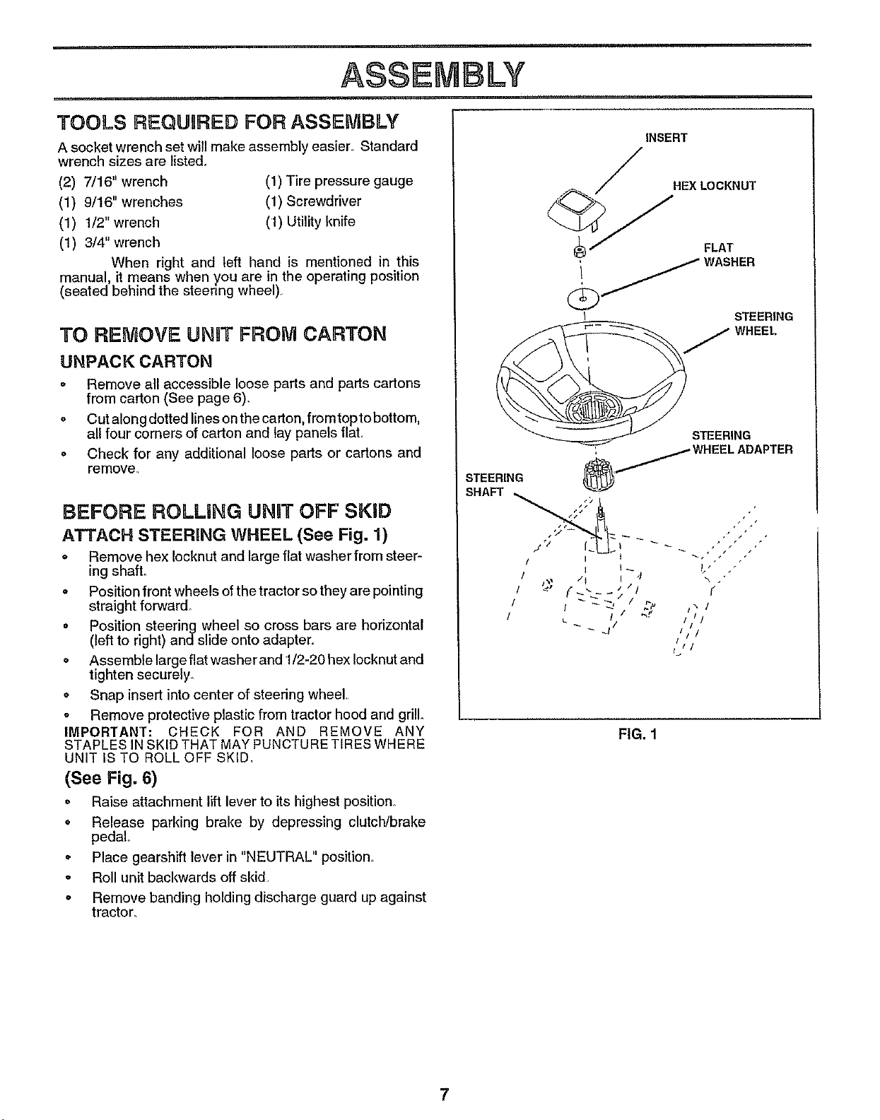
ATTACH STEERING WHEEL (See Fig. 1)
o Remove hex Iocknut and large flat washer from steer-
ing shaft.
° Position front wheels of the tractor so they are pointing
straight forward.
• Position steering wheel so cross bars are horizontal
(left to right) and slide onto adapter.
o Assemble large flat washerand 1/2-20 hex Iocknut and
tighten securely_
• Snap insert into center of steering wheel.
o Remove protective plastic from tractor hood and grill°
IMPORTANT: CHECK FOR AND REMOVE ANY
STAPLES IN SKID THAT MAY PUNCTURE TIRES WHERE
UNIT IS TO ROLL OFF SKID.
(See Fig. 6)
• Raise attachment lift lever to its highest position.
o Release parking brake by depressing clutch/brake
pedal
° Place gearshift lever in "NEUTRAL" position.
o Roll unit backwards off skid
o Remove banding holding discharge guard up against
tractor.
+'
¢
/i /
/11
FIG. 1
7

HOW TO SET UP YOUR TRACTOR
PREPARE BATTERY (See Fig. 2)
CAUTION: Wear eye and face shield.
Wash hands or clothing immediately if
accidentally incontactwith battery acid.
Do not smoke. Fumes from charged
battery acid are explosive.
Read theinstructionsincluded with the
battery vent caps. Always wear gloves,
clothing and goggles to protect your
hands, skin and eyes.
Your unit has a battery charging system which is sufficient
for normal use. However, periodic charging ofthe battery
with an automotive charger will extend its life
° See instructions packed with vent caps in parts bag
Fill battery with acid_ Fill each cell until it reaches the
bottom of the vent wells. Do not overfill.
o Allow battery to stand and settle for at least thirty
minutes After standing, check the level of acid If
below the vent wells, add more acid until the correct
level is reached_
While battery is standing (after adding acid) and later, while
battery is being charged, continue with assembly of uniL
IMPORTANT: TO MAXIMIZE THE LiFE OF YOURBATTERY,
IT IS NECESSARY THAT THE BATTERY BE CHARGED BE-
FORE USE° FAILURETO CHARGE BATTERY CAN RESULTIN
A SHORTENED BA'Iq'ERY LIFE.
o Charge battery at a rate of 6 amperes for' 1 hour.
Observe all safety precautions required for battery
charging.
o Check the acid level after the battery is charged. If the
acid has fallen below the correct level, add distilled or
iron free water.
° Install the vent caps to coverthe vent wells_ Wash the
top of the battery with water to remove any acid, then
wfpe dry_
o Check battery case for leakage to make sure that no
damage has occurred in handling.
o Dispose of excess battery acid Neutralize acid for'
disposal by adding it to four inches of water in a five
gallon plastic container_ Stir' with a wooden or plastic
paddle while adding baking soda until the addition of
more soda causes no more foaming.
° Follow instructions on how to install battery
CUT AWAY VIEW
I "-F -_VENT CAP
CELL ACID
LEVEL
iNSTALL SEAT (See Fig. 3)
Adjust seat before tightening adjustment boll
o Remove cardboard packing on seat pan.
o Place seat on pan and assemble shoulder boll
o Assemble adjustment bolt, lock washer and flat washer
_oose_y_Do not tighten.
o Tighten shoulder bolt securely.
• Lower seat into operating position and sit on seat.
o Slideseat untilacomfortablepositionisreachedwhich
allows you to press clutch/brake pedal alltire way down
(See Fig 6)
° Get off seat without moving its adjusted position.
o Raise seat and tighten adjustment bolt securely..
SEAT
SEAT PAN
SHOULDER
BOLT
FLATWASHER
ADJUSTMENT LOCKWASHER
BOLT
FIG. 3
CHECK TIRE PRESSURE
The tires on your unit were overinflated at the factory for
shipping purposes. Correct tire pressure is important for
best cutting performance_
o Reduce tire pressure to PSI shown in "PRODUCT
SPECIFICATIONS" on page 3 of this manual°
CHECK DECK LEVELNESS
Forbest cuttingresults, mower housingshould be ,properly
leveled_ See TO LEVEL MOWER HOUSING in the
Service and Adjustments section of this manual.
CHECK FOR PROPER POSITION OF ALL
BELTS
See the figures that are shown for replacing motion and
mower blade drive belts in the Service and Adjustments
section of this manual. Verify that the belts are routed
correctly_
CHECK BRAKE SYSTEM
After you learn how to operate your tractor, check to see
that the brake is properly adjusted. See "TO ADJUST
BRAKE" in the Service and Adjustments section of this
manual.
FIG. 2 8

ASSEMBLY
iNSTALL BATTERY (See Figs. 4 & 5)
CAUTION: Do not short battery termi-
nals. Before installing battery, remove
rings, etc.
metal bracelets, wristwatch bands,
Positive terminal must be connected
first to prevent sparking from acciden-
tal grounding.
o Make sure draintube isfastened to drain hole in battery
tray and battery tray is positioned in hole of battery
supporL
o Place battery in plastic tray, battery terminals to front of
tractor.
o First connect RED battery cable to positive (+) battery
terminal with hex bolt, flat washer, lock washer and hex
nut as shown Tighten securely
o Connect BLACK grounding cable to negative (-) bat-
tery terminal with remaining hex bolt, flat washer, lock
washer and hex nut. Tighten securely.
• Slide the two battery bolts through the terminal guard
and start the wing nuts onto the threads
• Position terminal guard over the battery as shown,
lower bolts into key holes and slide square shafts of
bolts into slots of key hole&
o Tighten wing nuts by hand making sure battery bolts
remain in slots of the key holes in the battery support.
= Be sure terminal access doors are closed.
Use terminal access doors for:
o Inspection for secure connections (to tighten hard-
ware).
, Inspection for corrosion.
o Testing battery.
o Jumping (if required).
Periodic charging.
LOCK _::,_.:.::;;..y- .,...... . HEX LOCI{ WASHER
WASHER . ,.., ,., dj_
(NEGATIVE) '_ WASHER
"=-_;'-" --' : NUT /
;"
(POSITIVE)
FLAT
ASSEMBLE GAUGE WHEELS TO NIOWER
DECK (See Fig. 6)
Assemble gauge wheels with tractor on a flat level surface.
o Lower mower to lowest position with attachment lift
lever..
• Adjust mower to desired cutting height with height
adjustment knob ( see "TO ADJUST MOWER CUT-
TING HEIGHT in operation section of this manual)
• With mower in desired height of cut position, gauge
wheels should be assembled so they are slightly off the
ground. Install gauge wheel in appropriate hole with
hardware shown and tighten securely.
o Repeat for opposite side installing gauge wheel in
same adjustment hole.
'GAUGE WHEEL FLAT WASHER
MOUNTING \
BRACKET
FLANGE
LOCKNUT
GAUGE WHEEL
_/SHOULDER BOLT
FIG. 6
•/ CHECKLIST
BEFORE YOU OPERATE AND ENJOY YOUR NEW
TRACTOR, WE WISH TOASSURE THAT YOU RECEIVE
THEBESTPERFORMANCEAND SA TISFA CTIONFROM
THIS QUALITY PRODUCT.
Please review the following checldist:
,/ All assembly instructions have been completed.
,/ No remaining loose parts in carton
v" Battery is properly prepared and charged. (Minimum
1 hour at 6 amps).
,/ Seat is adjusted comfortably and tightened securely.
,/ All tires are properly inflated. (For shipping purposes,
the tires were over-inflated at the factory).
,/ Be sure mower deck is properly leveled side-to-side/
front-to-rear for best cutting results (Tires must be
properly inflated for leveling)
,/ Checkmoweranddrivebelts. Besuretheyarerouted
properly around pulleys and inside all belt keepers
,/ Check wiring. See that all connections are still secure
and wires are properly clamped
WHILELEARNING HO W TO USE YOUR TRA CTOR, PAY
EXTRA ATTENTION TO THE FOLLOWING IMPORTANT
ITEMS:
,/ Engine oil is at proper level
#" Fuel tank is filled with fresh, clean, regular unleaded
gasoline.
,/ Become familiar with all controls - their location and
function. Operate them before you start the engine
,f Be sure brake system is in safe operating condition.
9

OPERATION
ill.... ii I
KNOW YOUR TRACTOR
READ THIS OWNER'S MANUAL AND SAFETY RULES BEFORE OPERATING YOUR TRAC-
TOR
Compare the illustrationswith your tractor to familiarize yourself with the locations of variouscontrols and adjustments_ Save
this manual for future reference
ATTACHMENT CLUTCH LEVER
PLUNGER
LIGHT SWITCH SWITCH
THROTTLE CONTROL
CHOKE
IGNITION
ATTACHMENT'
LIFT LEVER
CLUTCH/BRAKE
PEDAL
PARKING
HEIGHT GEARSHIFT
ADJUSTMENT LEVER
KNOB
FIG. 7
Sears tractors conform to the safety standards of the American National Standards Institute,
THROTTLE CONTROL: Used for starting and corrtrolling
engine speed.,
CHOKE CONTROL: Used for starting a cold engine_
CLUTCH/BRAKE PEDAL: Used for clutching and braking
the tractor and starting the engine.
HEIGHT ADJUSTMENT KNO B: Used to adjust the mower
cutting height,
IGNITION SWITCH: Used for starting and stopping the
engine.
LIGHT SWITCH: Turns the headlights on and off_
ATrACHMENT CLUTCH LEVER: Used to engage the
mower blades, or other attachments mounted to your
tractor.
LIFT LEVER PL,UNGER: Used to release attachment lift
lever when changing its position,
ATTACHMENT LIFT LEVER: Used to raise and lower the
nrowerdeck or other attachments mounted to your' tractor.
PARKING BRAKE LEVER: Locks ClutcfVBrake Pedal into
the brake position_
GEARSHIFT LEVER: Selects the speed and direction of
tractor.
10

OPERATION
The operation of any tractor can result in foreign objects thrown into the eyes, which
can result in severe eye damage_ Always wear safety glasses or eye shields while
operating your tractor or performing any adjustments or repairs, We recommend wide
vision safety mask for over the spectacles or standard safety glasses, available at Sears
Retail or Catalog stores_
HOW TO USE YOUR TRACTOR
TO SET PARKING BRAKE (See Fig. 8)
Depress clutch/brake pedal into full "BRAKE" position
and hold.
Place parking brake lever in "ENGAGED"position and
release pressurefrom clutch/brake pedal Pedal should
remain in "BRAKE" positiom Make sure parking brake
will hold vehicle secure.
STOPPING (See Fig. 8)
MOWER BLADES -
Move attachment clutch lever to "DISENGAGED" po-
sition.
GROUND DRIVE-
Depress clutch/brake pedal into full "BRAKE" positiom
Move gearshift lever to "NEUTRAL" position.
ENGINE -
Move throttle control to "SLOW" position,
NOTE: Failure to move throttle control to "SLOW" position
and allowing engine to idle before stopping may cause
engine to "backfire".
Turn ignition Key to "OFF" position and remove key.
Always remove key when leaving vehicle to prevent
unauthorized use.
Never use choke to stop engine.
NOTE: Under certain conditions when unit isstanding idle
with the engine running, hot engine exhaust gases may
cause "browning" of grass, To eliminate this possibility,
always stop engine when stopping unit on grass areas.
as described above, before leaving the
operator's poeltlon; to empty grass
CAUTION: Always stop unit completely, i
catcher, etc.
TO USE THROTTLE CONTROL (See Fig. 8)
Always operate engine at full throttle.
Operating engine at less than full throttle reduces the
battery charging rate.
Full throttle offers the best bagging and mower per-
formance.
TO MOVE FORWARD AND BACKWARD
(See Fig. 7)
The direction and speed of movement is controlled by the
gearshift lever,
Start tractor with clutch/brake pedal depressed and
gearshift lever in "NEUTRAL" position.
Move gearshift lever to desired position.
Slowly release clutch/brake pedal to start movement. 1 1
IMPORTANT: BRING TRACTOR TO A COMPLETE STOP
BEFORE SHIFTING OR CHANGING GEARS. FAILURE
TO DO SO WILL SHORTEN THE USEFUL LIFE OF YOUR
TRANSAXLE,
ATTACHMENT
THROTTLE "ENGAGED"
CHOKE
"BRAKE"
POSITION
CLUTCH/BRAKE
PEDAL"DRIVE
POSITION
CLUTCH LEVER
POSITION
IGNITION KEY
GEAR SHIFT
LEVER
FIG. 8
TO ADJUST MOWER CUTTING HEIGHT
(See Fig. 9)
The cuttingheight is controlled byturningthe heightadjust-
ment knob in desired direction.
Turn knob clockwise to raise cutting height
Turn knob counterclockwise to lower cutting height
Thecutting height rangeis approximately 1-1/2to 4" The
heights are measured from the ground to the blade tip with
the engine not running, These heights ere approximate
and may vary depending upon soil conditions, height of
grass and types of grass being mowed.
The average lawn should be cut approximately 2-1/2
inches during the cool season and over 3 inches during
hot months_ For healthier and better looking lawns,
mow often and after moderate growth,
For best cutting performance, grass over 6 inches in
height should be mowed twice. Make the first cut
relatively high; the second to desired height,
HEIGHT
ADJUSTMENT
KNOB
RAISE
)-
_, LOWER
FIG, 9

OPERATION
TO OPERATE MOWER (See Fig. 10)
Your unit is equipped with an operator presence sensing
switch Any attempt by the operator to leave the seat with
the engine running and the attachment clutch engaged will
shut olf the engine.
o Select desired height of cuL
, Engage mower by slowly moving attachment clutch
lever to "ENGAGED' position
• TO STOP MOWER - Move attachment clutch lever to
"DISENGAGED" position.
i
without either the entire grass catcher, on
!_ CAUTION: DO not operate the mower
mowers so equipped, or the discharge
guard in place.
ATTACHMENT "ENGAGED" POSITION
CLUTCH LEVER
"DISENGAGED" LIFT LEVER
POSITION PLUNGER
ATTACHMENT CLUTCH LEVER
LOWEST
POSITION
o Ifstopping is absolutely necessary push clutch/brake
pedal quickly to brake position and engage parking
brake.
o Move gearshift lever' to 1st gear and be sure you have
allowed room for tractor to roll slightly as you restart
movement.
o To restart movement, slowly release parkingbrake and
clutch/brake pedal
o Make all turns slowly.
TO TRANSPORT
° Raise attachment lift control to highest position.
° When pushing or' towing your unit, be sure gearshift
lever is in "NEUTRAL" position.
° Do not push or tow unit at more than five (5) MPH.
BEFORE STARTaNG THE ENGINE
CHECK ENGINE OIL LEVEL (See Fig. 15)
• The engine in your' unit has been shipped, from the
factory, already filled with summer weight oil.
° Check engine oil with unit on level ground.
o Remove oil fill dipstick and wipe clean, replace and
screw cap tight, wait for a few seconds, remove and
read oil level If necessary, add oil until "FULL" mark
on dipstick is reached. Do not overfill.
o For cold weather operation you should change oil for
easier starting (see "OIL VISCOSITY CHART" in the
Customer Responsibilities section of this manual)..
° To change engine oil, see the Customer Respensibili-
ties section in this manual
HEIGHT
ADJUSTMENT
KNOB
LIFT LEVER
"HIGHEST"
POSITION
FIGo10
TO OPERATE ON HILLS
i,i H, ,,, ,I
I ,#_ CAUTION: Do not drive up or down hills
H ,,,ll
o Choose theslowest speed before starting upor down
• Avoid stopping or changing speed on hills.
° If slowing is necessary, move throttle control lever to
with slopes greater than 15° and do not
drive across any slope.
hills.
slower position.
ADD GASOLINE
° Fill fuel tank_ Use fresh, clean, regular unleaded
gasoline_ (Use of leaded gasoline willincrease carbon
and lead oxide deposits and reduce valve life).
IMPORTANT; WHENOPERATING INTEMPERATURES
BELOW 32°F(0°C), USE FRESH, CLEAN WINTER GRADE
GASOLINE TO HELP INSURE GOOD COLD WEATHER
STARTING
WARNING: Experience indicates that alcohol blended
fuels (called gasohol or using ethanol or methanol) carl
attract moisture which leads to separation and formatton of
acids during storage_ Acidic gas can damage the fuel
system of an engine while in storage. To avoid engine
problems, the fuel system should be emptied before stor-
age of 30 days or longer. Drain the gas tank, start the
engine and let it run until the fuel lines and carburetor are
empty. Use fresh fuel next season See Storage Instruc-
tions for additional inforrnation_ Never use engine or
carburetor cleaner products in the fuel tank or permanent
damage may occur.
.#% CAUT'iON:' Filli0 bottom of gas tank filler-]
A A neck. Do not overfill. Wipe off any spilled|
oil or fuel Do not store, spill or use/
gasoline near an open flame. |
12

TO START ENGINE (See Fig. 8)
When starting engine for the first time or if engine has
run out of fuel, it will take extra cranking time to move
fuel from the tank to the engine
• Depress the clutch/brake pedal and set the parking
brake.
o Place gearshift lever in "NEUTRAL" position.
o Move attachment clutch to "DISENGAGED" position,
• Pull choke control out to "CHOKE"position for cold
engine start. For warm engine start do not use choke
control
° Move throttle control to midway between "FAST" and
"SLOW" positions_
per minute. If engine does not start after several
attempts, move throttle control to "FAST" position,
wait a few minutes and try again_
o When engine starts, slowly push choke control in.
o Move throttle control to "FAST" position.
o Allow engine to warm up for a few minutes before
engaging drive or attachment clutch.
NOTE; If at a high altitude (above 3000 feet) or in cold
temperatures (below 32° F), the carburetor fuel mixture
may need to be ad usted for best engine performance.
See "TO ADJUST CARBURETOR" in the Service and
Adjustments section of this manual.
NiOWgNG TiPS
= Tire chains cannot be used when the mower hous_
ing is attached to unit,
o Mower should be properly leveled for best mowin_
performance. See TO LEVEL MOWER HOUSING
m the Service and Adjustments section of this
manual.
• The left hand side of mower should be used for trim-
ruing.
Drive so that clippings are discharged onto the area
that has been cuL Have the cut area to the right of
the machine. This will result in a more even distri-
bution of clippings and more uniform cutting
When mowing large areas, start by turning to the
right so that clippings will discharge away from
shrubs, fences, driveways, etc. After one or two
rounds, mow in the opposite direction making left
hand turns until finished(See Fig. 11)_
f
C
FIG, l't
If grass is extremely tall, it should be mowed twice
to reduce load and possible fire hazard from dried
clippings° Make first cut relatively high; the second
to the desired heighL
Do not mow grass when it is wet. Wet grass will
plug mower and leave undesirable clumps. Allow
grass to dry before mowing_
Always operate engine at full throttle when mowing
to assure better mowing performance and proper
discharge of material. Regulate ground speed by
selecting a low enough speed to give the mower
cutting performance as well as the quality of cut de-
sired.
When operating attachments, select a ground speed
that will suit the terrain and give best performance of
the attachment being used,
13

CUSTOM ESPONSNBJLUTHES
MAINTENANCE
FILL IN DATES
AS YOU COMPLETE
REGULAR SERVICE
sc.,ou,_,
Check Brake Operation _#'
Check Tire Pressure
T Check for Loose Fasteners 6#4
a Sharpen/Replace Mower Blades
_ Lubrication Chad
T Check Battery Level/Recharge
0 Clean Battery and Terminals
R Check Transmission Cooling
Adjust Blade Belt(s) Tension
Adjust Motion Drive Belt(s) Tension
i
Check Engine Oil Level I_
Change Engine OII
Clean Air Filter
E
v'
v'
_4
v' v'
e,' e,'
_1,2,3
V'2
N Clean Air Screen
G Inspect Muffler/SparkArrester
I Replace Oil Filter (if equipped)
N Clean Engine Cooling Fins
Replace Spark Plug
Replace Air Filter Paper Cartridge
Replace Fuel Filter
I - Change mote oftenwhen operating under a heavy loador Inhigh ambient temperatures
2 - Service mole often when operating inditty or dusty conditions
e,,'
v'
V's
, r ,'.,
v'
e,"
v'
v',
v'
3-Ifequlppedwithollf_lter,changeollevery50hours
4• ReplacebladesmoreoftenwhenmowingInsandysoil
5• Ifequippedwithadjustablesystem
GENERAL RECOMMENDATIONS
The warranty on this vehicle does not cover' items that have
been subjected to operator abuse or negligence. To
receive full value from the warranty, operator must main-
rain unit as instructed in this manual
Some adjustments will need to be made periodically to
properly maintain your unit.
All adjustments in the Service and Adjustments section of
this manual should be checked at least once each season.
Once a year you should replace the spark plug, clean
or replace air filter, and check blades and belts for Q
wear. A new spark plug and clean air filter assure CLUTCH
proper air-fuel mixture and help your engine run better PIVOT(S)
andlast longer.
BEFORE EACH USE
Check engine oi! level.
Check brake operation.
Check tire pressure,
Check for loose fasteners
@ "FRONT WHEEL (_)
(_ SAE 30 OR 10W30 MOTOR OIL APt - SG
(_) GENERAL PURPOSE GREASE
(_ REFER TO CUSTOMER RESPONSIBILITIES "ENGINE" SECTION
IMPORTANT: DO NOT OIL OR GREASE THE PIVOT POINTS
WHICH HAVE SPECIAL NYLON BEARINGS VISCOUSLUBRI•
CANTS WILL ATTRACT DUST AND DIRT THAT WILL SHORTEN
THE LIFE OF THE SELF-LUBRICATING BEARINGS, IF YOU
FEEL THEY MUST BE LUBRICATED USE ONLYADRY, POW-
14 DERED GRAPHITE TYPE LUBR CANT SPAR NGLY.
LUBRICATION CHART
BEARING ZERK _ BEARING ZERK

CUSTOMER RESPONSUBILITUES
i IMI
TRACTOR TO SHARPEN BLADE (See Fig. 13)
Always observe safety rules when performing any mainte- Care should be taken to keep the blade balanced. An
nance, unbalanced blade will cause excessive vibration and even-
tual damage to mower and engine.
BRAKE OPERATION
If unit requires more than six (6) feet stoppingdistance at
high speed in highest gear, then brake mustbe adjusted.
(See "TO ADJUST BRAKE in Service and Adjustments
section of this manual).
TIRES
o Maintainproper air pressure in all tires (See "PROD-
UCT SPECIFICATIONS" on page 3 of this manual),
• Keep tires free of gasoline, oil, or insect control chemi-
cals which can harm rubber,,
• Avoid stumps, stones, deep ruts, sharp ob ects and
other hazards that may cause t re damage
BLADE CARE
For best results mower blades must be kept sharp, The
blades can be sharpened with a file or on a grinding wheel.
We suggest they be sharpened or replaced after every 25
hours of mowing Check blades more often if mowing in
sandy condition&
o Do not attempt to sharpen blades while they are on the
mower,
• Replace bent or damaged blades.
BLADE REMOVAL (See Fig. 12)
° Raise mower to highest position to allow access to
blades
o Remove hex bolt, lockwasher and flat washer securing
blade.
o install new or resharpened blade withtrailing edge up
towards deck as shown.
• Reassemble hex bolt, lock washer and flat washer in
exact order as shown.
° Tighten bolt securely (30-35 FL Lbs. torque).
IMPORTANT: BLADE BOLT IS GRADE 8 HEAT
TREATED.
. The blade can be sharpened with a file or on a grinding
wheel. Do not attempt to sharpen while on the mower
o To check blade balance you will need a 5/8" diameter
steel bolt,pin, or cone balancer, (When using a cone
balancer, follow the instructions supplied with the bal-
ancer).
o Slide b[ade on to an unthreaded portion of the steel bolt
or pin parallel with ground. If blade is balanced, it
should remain in a horizontal position. If either end of
the blade moves downward, sharpen the heavy end
until the blade is balanced
NOTE: Do not use a nail for balancing blade. The lobes of
the center hole may appear to be centered, but are not,
FIG. 13
BATTERY (See Fig. 14)
Your unithas a battery charging system which is sufficient
for normal use. However, periodic charging ofthe battery
with an automotive charger will extend it'slifeo
° Acid solution level in each battery cell should be even
with bottoms ofvent wells. Add onlydistilledor ironfree
water if necessary. Do not overfill.
- Keep battery and terminals clean.
• Keep battery bolts tighL
° Keep vent capstight and smallvent holesin caps open,
o Rechargeat 6amperesforl hour.
MANDREL
FLATWASHER
BLADE
LOCK WASHER
HEXBOLT
(GRADE8
*A GRADE 8 HEAT TREATED BOLT CAN BE IDENTIFIED
BY SIX LINES ON THE BOLT HEAD.
FIG. 12
TRAILING EDGE
CUT AWAY VIEW .-VENT CAP
{L----i"_-L__.._j -_/VENT
WELL
I [_ N _ N N }} N N # bBATTERY
I _ _ _ [_ riJ _ _] _,,_ CELLACID
VEL
FIG. 14
15
 Loading...