

Craftsman 917257720 Owner’s Manual

L NUMBER 917.257720 OWNER'SMANUAL
Assembly
Operation
Customer Responsibilities
Service and Adjustments
Repair Parts
CAUTION: Read and follow all safety rules and instructions before operating this equipment,

Safe Operation Practices for Ride-On Mowers
SAFETY RULES
IMPORTANT: THIS CUTTING MACHINE IS CAPABLE OFAMPUTATING HANDSAND FEETAND THROWING OBJECTS.
FAILURE TO OBSERVE THE FOLLOWING SAFETY INSTRUCTIONS COULD RESULT IN SERIOUS INJURY OR DEATH.
L GENERAL OPERATION
* Read, understand, and follow all instructions in the manual
and on the machine before starting.
Only allow responsible adults, who are familiar with the
instructions, to operate the machine.
Clear the area of objects such as rocks, toys, wire, etc.,
which could be picked up and thrown by the blade.
* Be sure the area is clear of other people before mowing. Stop
machine if anyone enters the area.
, Never carry passengers.
- Do not mow in reverse unless absolutely necessary. Always
look down and behind before and while backing.
Be aware of the mower discharge direction and do not point
it at anyone. Do not operate the mower without either the
entire grass catcher or the guard in place.
Slow down before turning.
= Never leave a running machine unattended. Always turn off
blades, set parking brake, stop engine, and remove keys
before dismounting.
® Turn off blades when not mowing.
® Stop engine before removing grass catcher or unclogging
chute.
o Mow only in daylight or good artificial light.
o Do not operate the machine while under the influence of
alcohol or drugs.
- Watch for traffic when operating near or crossing roadways.
- Use extra care when loading or unloading the machine into
a trailer or truck.
IL SLOPE OPERATION
Slopes are a major factor related to loss-of-control and tipover
accidents, which can result insevere injury or death. All slopes
require extra caution. If you cannot back up the slope or ifyou feel
uneasy on it, do not mow it.
DO:
o
Mow up and down slopes, not across.
* Remove obstacles such as rocks, tree limbs, etc.
® Watch for holes, ruts, or bumps. Uneven terrain could
overturn the machine. Tafl grass can hide obstacles.
® Use slow speed. Choose a low gear so that you will not have
to stop or shift while on the slope.
Follow the manufacturer's recommendations for wheel
weights or counterweights to improve stability.
Use extra care with grass catchers or other attachments.
These can change the stability of the machine.
Keep all movement on the slopes slowand gradual Do not
make sudden changes in speed or direction.
o Avoid starting or stopping on a slope. If tires lose traction,
disengage the blades and proceed slowly straight down the
slope.
DO NOT:
Do not turn onslopes unless necessary, and then, turn slowly
and gradually downhill, if possible.
Do not mow near drop-offs, ditches, or embankments. The
mower could suddenly turn over if a wheel is over the edge
of a cliff or ditch, or if an edge caves in.
, Do not mow on wet grass. Reduced traction could cause
sliding.
. Donottrytostabilizethemachinebyputtingyourfootonthe
ground.
, Do not use grass catcher on steep slopes.
t11. CHILDREN
Tragic accidents can occur if the operator is not alert to the
presence of children. Children are often attracted to the machine
and the mowing activity. Neverassume that children will remain
where you last saw them.
* Keep children out ofthe mowing area and under the watchful
care of another responsible adult.
* Be alert and turn machine off if children enter the area.
, Before and when backing, look behind and down for small
children.
, Never carry children. They may fall off and be seriously
injured or interfere with safe machine operation.
- Never allow children to operate the machine.
* Use extra care when approaching blind corners, shrubs,
trees, or other objects that may obscure vision.
IV. SERVICE
- Use extra care inhandling gasoline and other fuels. They are
flammable and vapors are explosive.
Use only an approved container.
Never remove gas cap or add fuel with the engine
running. Allow engine to cool before refueling. Do not
smoke.
Never refuel the machine indoors.
Never store the machine or fuel container inside where
there is an open flame, such as a water heater.
• Never run a machine inside a closed area.
Keep nuts and bolts, especially blade attachment bolts, tight
and keep equipment in good condition.
Never tamper with safety devices. Check their proper
operation regularly.
, Keep machine free of grass, leaves, or other debris build-up.
Clean oil or fuel spillage. Allow machine to cool before
storing.
• Stop and inspect the equipment if you strike an object.
Repair, if necessary, before restarting.
, Never make adjustments or repairs with the engine running.
, Grass catcher components are subject towear, damage, and
deterioration, which could expose moving parts or allow
objects to be thrown. Frequently check components and
replace with manufacturer's recommended parts, when nec o
essary.
Mower blades are sharp and can cut. Wrap the blade(s) or
wear gloves, and use extra caution when servicing them.
- Check brake operation frequently. Adjust and service as
required.
Look for this symbol to point out impor-
tant safety precautions. It means
CAUTION!!! BECOME ALERT!!! YOUR
SAFETY IS INVOLVED.
CAUTION: Always disconnect spark
plug wire and place wire where it cannot
contact spark plug in order to prevent
accidental starting when setting up,
transporting, adjusting or making
repairs,
2

CONGRATULATIONS on your purchase of a Sears
Tractor. It has been designed, engineered and manufac-
tured to give you the best possible dependability and
performance.
Should you experience any problem you cannot easily
remedy, please contact your nearest Sears Authorized
Service Center/Department. We have competent, well-
trained technicians and the proper tools to service or repair
this unit.
Please read and retain this manual. The instructions will
enable you to assemble and maintain your unit properly.
Always observe the "SAFETY RULES".
MODEL
NUMBER 917.257720
SERIAL
NUMBER
DATEOFPURCHASE
THE MODELANDSERIALNUMBERS WILL BE FOUND
ON A PLATE UNDER THE SEAT.
YOU SHOULD RECORD BOTH SERIAL NUMBER AND
DATE OF PURCHASE AND KEEP IN A SAFE PLACE
FOR FUTURE REFERENCE.
PRODUCT SPECIFICATIONS
HORSEPOWER: 18.0
GASOM NE CAPACITY 3,5 GALLONS
AND TYPE: UNLEADED REGULAR
OIL TYPE (API-SG): SAE 30 (above 32°F)
SAE 5W-30 (below 32°F)
OILCAPACITY: W/FILTER: 4.0 PINTS
W/O FILTER: 3.5 PINTS
SPARK PLUG: CHAMPION RV17YC
(GAP: .025")
VALVE CLEARANCE: INTAKE: .003" - .006"
EXHAUST: .016" - .019"
GROUND SPEED (MPH): Forward L.O Ht
1st 0.8 1.8
2nd 1.4 3.4
3rd 2.4 5.6
Reverse 0.9 2.2
TRANSAXLE OIL 4 QUARTS
CAPACITY AND TYPE: SAE 30 API-SG
TIRE PRESSURE: FRONT: 14PSI
REAR: 10 PSI
CHARGING SYSTEM: 15 AMPS @ 3600 RPM
BLADE BOLT TORQUE: 30-35 FT. LBS.
MAINTENANCE AGREEMENT
A Sears Maintenance Agreement is available on this prod-
uct. Contact your nearest Sears store for details.
WARNING: This unit is equipped with an internal combus-
tion engine and should not be used on or near any unim-
proved forest-covered, brush-covered or grass-covered
land unless the engine's exhaust system is equipped with
a spark arrester meeting applicable local or state laws (if
CUSTOMER RESPONSNBILmTIES
o Read and observe the safety rules.
o Follow a regular schedule in maintaining, caring for and
using your unit.
Follow the instructions under "Customer Responsibili-
ties" and "Storage" sections of this owner's manual.
any). If a spark arrester is used, it should be maintained in
effective working order by the operator.
In the state of California the above is required by law
(Section 4442 of the California Public Resources Code).
Other states may have similar laws. Federal laws apply on
federal lands. A spark arrester for the muffler is available
through your nearest Sears Authorized Service Center/
Department (See REPAIR PARTS section ofthis manual).
LmMR'ED TWO YEAR WARRANTY ON ELECTRIC START RIDING EQUIPMENT
For two (2) years from the date of purchase, if this riding equipment is maintained, lubricated and tuned up according to the
instructions in the owner's manual, Sears will repair or replace, free of charge, any parts found to be defective in material or
workmanship.
This Warranty does not cover:
o Expendable items which become worn during normal use, such as blades, spark plugs, air cleaners and belts.
o Tire replacement or repair caused by punctures from outside objects, such as nails, thorns, stumps, or glass.
o Repairs necessary because of operator abuse, negligence, improper storage or accident or the failure to maintain the
equipment according to the instructions contained in the owner's manual:
Riding equipment used for commercial or rental purposes.
LIMITED 90 DAY WARRANTY ON BATTERY
For ninety (90) days from date of purchase, if any battery included with this riding equipment proves defective in material or
workmanship and our testing determines the battery will not hold a charge, Sears will replace the battery at no charge.
WARRANTY SERVICE tS AVAILABLE BY RETURNING THE RIDING EQUIPMENT TO THE NEAREST SEARS SERVICE
CENTER/DEPARTMENT INTHE UNITED STATES.
This Warranty gives you specific legal rights, and you may also have other rights which may vary from state to state.
SEARS, ROEBUCK AND CO., D/817 WA, HOFFMAN ESTATES, ILLINOIS 60179
3

TA LE OF CON TS
SAFETY RULES ............................................................ 2
PRODUCT SPECIFICATIONS ....................................... 3
CUSTOMER RESPONSIBILITIES ..................... 3, 15-18
WAR RANTY ................................................................... 3
TRACTOR ACCESSORIES ........................... ................ 5
ASSEMBLY .............................................................. 7-10
OPERATION ........................................................... 11-14
INDEX
A
Accessories ........................................... 5
Adjustments:
Brake ............................................ 21
Carburetor .................................... 25
Clutch Pulley ................................ 21
Gauge Wheels ............................. 13
Mower
Front-To-Back ........................ 20
Side-To-Side ........................... 19
Throttle Control Cable .................. 25
Air Filter, Engine .................................. 18
Air Screen. Engine ............................... 18
Assembly .......................................... 7-10
B
Battery:
Charging ......................................... 8
Cleaning ....................................... 16
Installation .................................... 10
Levels ........................................ 8.16
Preparation ..................................... 8
Starting with Weak Battery ........... 21
Storage ......................................... 24
Terminals ...................................... 17
Belt:
Motion Drive
Removal/Replacement ............ 22
Mower Drive
Removal/Replacement ............ 20
Mower Blade Drive
Removal/Replacement ............ 21
Blade:
Sharpening ................................... 16
Replacement ................................ 16 Lubrication:
Brake Adjustment ................................ 21
C
Carburetor Adjustment ....................... 25
Clutch Pulley ........................................ 21
Controls. Tractor .................................. 11
Customer Responsibilities .............. 15-18
Engine:
Air Filter .................................... 18
Air Screen ................................. 18
Cooling Fins ............................. 18
Engine Oil ............................ 13,16
Fuel Filter ................................. 18
Spark Plug(s) ............................. 18
Tractor:
Battery ..................................... 17
Blade ........................................ 14
Lubrication Chart ...................... 15
Maintenance Schedule ............. 15
Tire Care .......................... 8,15,21
Transaxle .................................. 16
Cutting Height, Mower ......................... 12
Electrical:
Interlocks and Relays ................... 22
Schematic ..................................... 30
Wiring Diagram ............................. 32
Engine:
Air Filter ........................................ 18
Air Screen ..................................... 18
Cooling Fins ................................. 18
Oil Change ................................... 17
Oil Level ....................................... 17
Oil Type .................................. 13,17
Preparation ................................... 13
Repair Parts ............................ 48-57
Starting .................................... 13.14
Storage ......................................... 26
Filter:
Air Filter ........................................ 18
Fuel .............................................. 18
Oil ................................................. 18
Fuel:
Storage ......................................... 26
Type ............................................. 14
Fuse .................................................... 22
Headlights ............................................ 24
Hood Removal/Installation ................... 24
Leveling Mower Deck .......................... 19
Chart ............................................. 15
Engine .......................................... 16
Maintenance Schedule ........................ 15
Mower:
Adjustment, Front-to-Back ............ 19
Adjustment, Side-to-Side .............. 19
lade Replacement ...................... 16
Blade Sharpening ......................... 16
Cutting Height ............................... 12
Installation .................................... 19
Operation ...................................... 13
Removal ....................................... 19
Mowing Tips ........................................ 14
Muffler .................................................. 18
Spark Arrester ........................... 3,38
Oil:
Cold Weather Conditions ........ 13.17
Engine .......................................... 17
Storage ......................................... 26
MAINTENANCE SCHEDULE ...................................... 15
SERVICE AND ADJUSTMENTS ............................ 19-25
STORAGE .................................................................... 26
TROUBLESHOOTING ............................................ 28=29
REPAIR PARTS =TRACTOR ................................. 31-47
REPAIR PARTS - ENGINE ..................................... 48°57
PARTS ORDERING/SERVICE ................ BACK COVER
E
Operation ........................................ 11-14
Operating Mower ................................. 13
Options:
Accessories .................................... 5
Spark Arrester ........................... 3,38
P
Parking Brake ................................. 11-12
Parts Bag ............................................... 6
Parts, Replacement/Repair ............ 31-47
Product Specifications ........................... 3
R
Repair Parts ................................... 3! -47
F
Safety Rules .......................................... 2
Seat ...................................................... 8
Service and Adjustments ................ 19-25
Carburetor .................................... 25
Clutch Pulley ................................ 21
Fuse ............................................ 23
Hood Removal/Installation ........... 24
Motion Drive Belt
Removal/Replacement ............ 22
H
L
M
Mower Drive Belt
Removal/Replacement ............ 20
Mower Blade Drive Belt
Removal/Replacement ............ 21
Mower Adjustment
Front-to-Back ........................... 20
Side-to-Side ............................. 19
Mower Removal/Installation ......... 18
Tire Care ............................... 8.15,21
Slope Guide Sheet .............................. 59
Spark Plug(s) ....................................... 17
Specifications ........................................ 3
Starting the Engine ......................... 13-14
Steering Wheel ................................. 7,22
Stopping the Tractor ............................ 12
Storage ................................................ 26
S
T
Throttle Control Cable Adjustment ...... 25
Tires ............................................. 8.15.21
Troubleshooting Chart ................... 28-29
Transax_e ................................... 16.46-47
W
O
Warranty ................................................ 3
WiringDiagram .................................... 32
Wiring Schematic ................................. 30
4
ESSORIES AND ATTAC ENTS
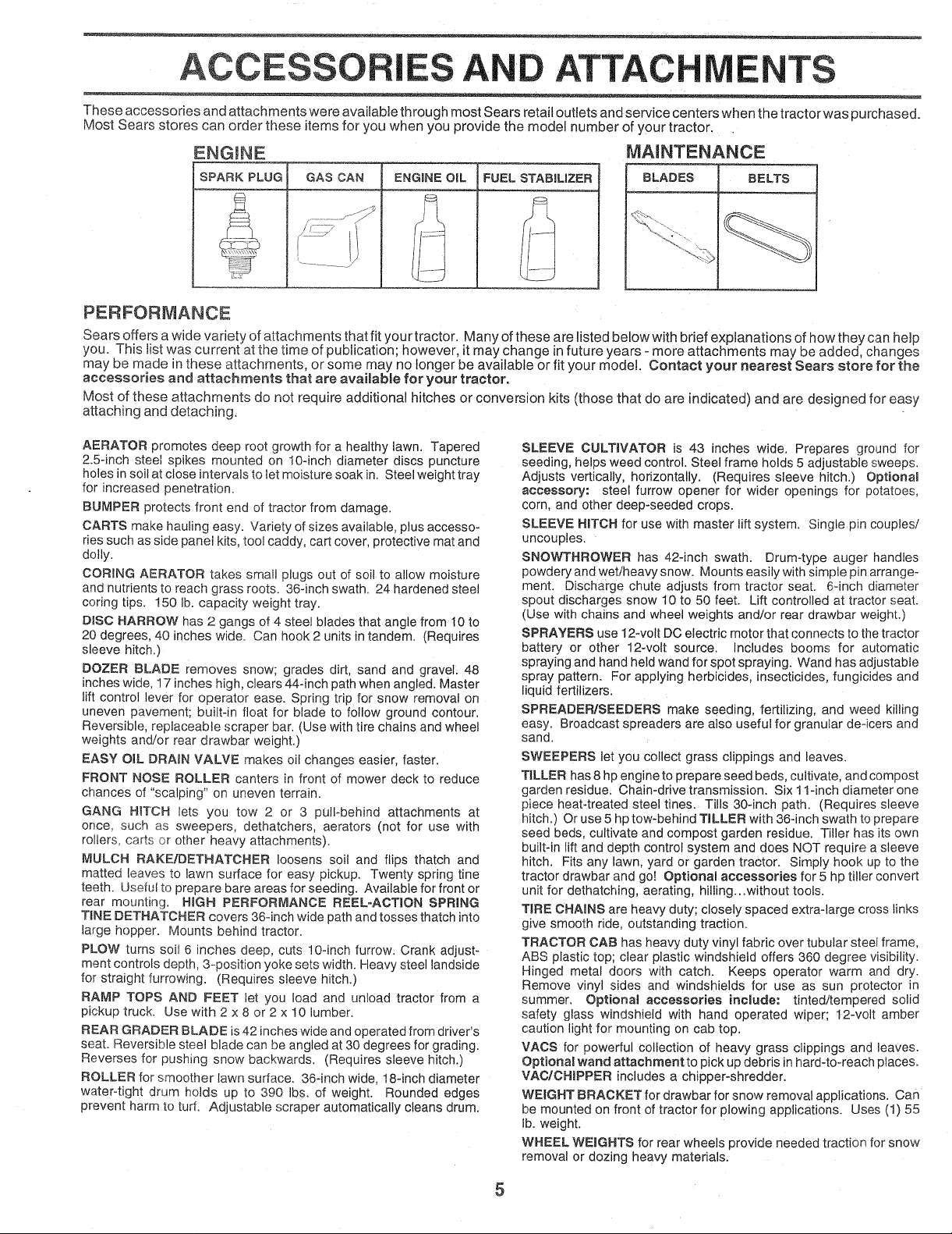
These accessories and attachments were available through most Sears retail outlets and service centers when the tractor was purchased.
Most Sears stores can order these items for you when you provide the model number of your tractor.
ENGINE
SPARK PLUG GAS CAN FUEL STABiLiZER
PERFORMANCE
Sears offers a wide variety of attachments that fit your tractor. Many of these are listed below with brief explanations of how they can help
you. This list was current at the time of publication; however, it may change in future years - more attachments may be added, changes
may be made in these attachments, or some may no longer be available or fit your model. Contact your nearest Sears store for the
accessories and attachments that are available for your tractor.
Most of these attachments do not require additional hitches or conversion kits (those that do are indicated) and are designed for easy
attaching and detaching.
MAINTENANCE
BLADES BELTS
AERATOR promotes deep root growth for a healthy lawn. Tapered
2.5-inch steel spikes mounted on 10-inch diameter discs puncture
holes in soil at close intervals to let moisture soak in. Steel weight tray
for increased penetration_
BUMPER protects front end of tractor from damage.
CARTS make hauling easy. Variety of sizes available, plus accesso-
ries such as side panel kits, toot caddy, cart cover, protective mat and
dolly.
CORING AERATOR takes small plugs out of soil to allow moisture
and nutrients to reach grass roots. 36-inch swath. 24 hardened steel
coring tips. 150 lb. capacity weight tray.
DISC HARROW has 2 gangs of 4 steel blades that angle from 10 to
20 degrees, 40 inches wide. Can hook 2 units in tandem. (Requires
sleeve hitch,)
DOZER BLADE removes snow; grades dirt, sand and gravel. 48
inches wide, 17 inches high, clears 44-inch path when angled. Master
lift control lever for operator ease. Spring trip for snow removal on
uneven pavement; built-in float for blade to follow ground contour,
Reversible, replaceable scraper bar. (Use with tire chains and wheel
weights and/or rear drawbar weight.)
EASY OHL DRAIN VALVE makes oil changes easier, faster.
FRONT NOSE ROLLER canters in front of mower deck to reduce
chances of "scalping" on uneven terrain.
GANG HF['OH lets you tow 2 or 3 pUll*behind attachments at
once, such as sweepers, dethatchers, aerators (not for use with
rollers, carts or other heavy attachments).
MULCH RAKE/DETHATCHER loosens soil and flips thatch and
matted leaves to lawn surface for easy pickup. Twenty spring tine
teeth. Useful to prepare bare areas for seeding. Available for front or
rear mounting. HiGH PERFORMANCE REEL=ACTION SPRING
TINE DETHATCHER covers 36-inch wide path and tosses thatch into
large hopper. Mounts behind tractor.
PLOW turns soil 6 inches deep, cuts 10-inch furrow. Crank adjust-
ment controls depth, 3-position yoke sets width. Heavy steel lands!de
for straight furrowing. (Requires sleeve hitch.)
RAMP TOPS AND FEET let you load and unload tractor from a
pickup truck. Use with 2 x 8 or 2 x 10 lumber.
REAR GRADER BLADE is 42 inches wide and operated from driver's
seat. Reversible steel blade can be angled at 30 degrees for grading.
Reverses for pushing snow backwards. (Requires sleeve hitch.)
ROLLER for smoother lawn surface. 36-inch wide, 18-inch diameter
water-tight drum holds up to 390 Ibm. of weight. Rounded edges
prevent harm to turf. Adjustable scraper automatically cleans drum.
SLEEVE CULTWATOR is 43 inches wide. Prepares ground for
seeding, helps weed control. Steel frame holds 5 adjustable sweeps.
Adjusts vertically, horizontally. (Requires sleeve hitch.) Optional
accessory: steel furrow opener for wider openings for potatoes,
corn, and other deep-seeded crops.
SLEEVE HITCH for use with master lift system. Single pin couples/
uncouples.
SNOWTHROWER has 42-inch swath. Drum-type auger handles
powdery and wet/heavy snow. Mounts easily with simple pin arrange-
ment. Discharge chute adjusts from tractor seat. 6qnch diameter
spout discharges snow 10 to 50 feet. Lift controlled at tractor seat.
(Use with chains and wheel weights and/or rear drawbar weight.)
SPRAYERS use 12wott DC electric motor that connects to the tractor
battery or other 12wolt source. Includes booms for automatic
spraying and hand held wand for spot spraying. Wand has adjustable
spray pattern. For applying herbicides, insecticides, fungicides and
liquid fertilizers.
SPREADER/SEEDERS make seeding, fertilizing, and weed killing
easy. Broadcast spreaders are also useful for granular de-icers and
sand.
SWEEPERS let you collect grass clippings and leaves.
TILLER has 8 hp engine to prepare seed beds, cultivate, and compost
garden residue. Chain-drive transmission. Six 11-inch diameter one
piece heat-treated steel tines. Tills 30-inch path. (Requires sleeve
hitch.) Or use 5 hp tow-behind TILLER with 36-inch swath to prepare
seed beds, cultivate and compost garden residue. Tiller has its own
built-in lift and depth control system and does NOT require a sleeve
hitch. Fits any lawn, yard or garden tractor. Simply hook up to the
tractor drawbar and go! OptionaU accessories for 5 hp tiller convert
unit for dethatching, aerating, hilling...without tools.
TiRE CHAINS are heavy duty; closely spaced extra-large cross links
give smooth ride, outstanding traction.
TRACTOR CAB has heavy duty vinyl fabric over tubular steel frame,
ABS plastic top; clear plastic windshield offers 360 degree visibility.
Hinged metal doors with catch. Keeps operator warm and dry.
Remove vinyl sides and windshields for use as sun protector in
summer, OptionaJ accessories incUude: tinted/tempered solid
safety glass windshield with hand operated wiper; 12-volt amber
caution light for mounting on cab top.
VACS for powerful collection of heavy grass clippings and leaves.
Optional wand attachment to pick up debris in hard-to=reach places_
VAC/CHIPPER includes a chipper-shredder.
WEIGHT BRACKET for drawbar for snow removal applications, can
be mounted on front of tractor for plowing applications. Uses (1) 55
lb. weight.
WHEEL WEIGHTS for rear wheels provide needed traction for snow
removal or dozing heavy materials.
5

CONTENTS ,OF E PACK
Parts Bag contents shown full size
......... 3
=
(1) Shoulder Bolt 5/16-18
(1) Knob
(1) Washer 17/32 x 1-3/!6 x 12 Gauge
Double Loop
_ etainer Springs
=
(4) Retainer Springs
Single Loop
Parts packed separately in carton
..... .- =
Seat
Battery acid
©
Steering Wheel
Battery
I 1
Parts Bag
Parts bag contents not shown full size
_ . =
(2) Gauge Wheels
(2) Shoulder Bolts
3/8 x 7/8 x 14 Gauge
Owner's Manual
(2) Washers Lock Nuts
©
(2)
(2) Hex Bolts 1/4-20 x 3/4
(2) Hex Nuts 1/4-20
(2) Washers 9/32 x 5/8 x 16 Ga.
(2) Lock Washers 1/4
(2) Wing Nuts 1/4-20
_t Link Assemblies
(2) Battery Carriage Bolts 1/4-20 x 7-1/2
Steering Wheel insert
(2) Keys
15° Slope Sheet
...... =
6
Terminal Guard
/ \
r
Battery Caps
and Instructions
Steering
Sleeve

BLY
Your newtractor has been assembled atthe factory with the exception of those parts left unassembled for shipping purposes,
To ensure safe and proper operation of your tractor all parts and hardware you assemble must be tightened securely. Use
the correct tools as necessary to insure proper tightness,
TOOLS REQUIRED FOR ASSEMBLY
A socket wrench set will make assembly easier. Standard
wrench sizes are listed.
(2) 7/16" wrenches Tire pressure gauge
(1) 1/2" wrench Utility knife
(1) 9/16" wrench
(1) 3/4" socket with drive ratchet
When right or left hand is mentioned in this manua, it
means when you are in the operating position (seated
behind the steering wheel).
TO REMOVE TRACTOR FROM CARTON
UNPACK CARTON
® Remove all accessible loose parts and parts cartons
from carton (See page 6).
® Cut, from top to bottom, along lines on all four corners
of carton, and lay panels flat.
o Remove mower and packing materials.
o Check for any additional loose parts or cartons and
remove.
BEFORE ROLLING TRACTOR OFF SKID
STEERING WHEEL iNSERT
_jHEX BOLT
LOCK WASHER
,_!;,_// LARGE FLAT
WASHER
STEERING
WHEEL
STEERING
SHAFT
STEERING
SLEEVE
ATTACH STEERING WHEEL (See Fig. 1)
* Remove hex bolt, lock washer and large flat washer
from steering shaft.
, Position front wheels of the tractor so they are pointing
straight forward,
o Slide steering sleeve over steering shaft,
o Position steering wheel so cross bars are horizontal
(left to right) and slide onto steering wheel adapter.
o Secure steering wheel to steering shaft with hex bolt,
Iockwasher and large flat washer previously removed
Tighten securely.
Snap steering wheel insert into center of steering
wheel.
Remove protective plastic from tractor hood and grill.
IMPORTANT: CHECK FOR AND REMOVE ANY STAPLES
IN SKID THAT MAY PUNCTURE TIRES WHERE TRACTOR
IS TO ROLL OFF SKID.
TO ROLL TRACTOR OFF SKiD (See Fig, 7)
o Raise attachment liftlever to its highest position.
o Release parking brake by depressing clutch/brake
pedal.
Place gearshift lever in neutral (N) position.
® Rol! tractor backwards off skid,
FIG. 1
7
ASSEM LY
HOW TO SET UP YOUR TRACTOR
PREPARE BATTERY (See Fig, 2)
CAUTION: Wear eye and face shield.
Wash Hands or clothing immediately if
accidentally in contact with battery acid.
Do not smoke. Fumes from charged
battery acid are e×pmosive.
Read the instructions included with the
battery vent caps. Always wear gloves,
c_othing and goggles to protect your
Hands, skin and eyes.
Your tractor has a battery charging system which is suffi-
cient for normal use. However, periodic charging of the
battery with an automotive charger wilt extend its life.
o See instructions packed with vent caps in parts bag.
Fill battery with acid. Fill each cell until it reaches the
bottom of the vent wells. Do not overfill.
Allow battery to stand and settle for at least thirty
minutes. After standing, check the battery cell acid
level. If below the vent wells, add more acid until the
correct level is reached.
While battery is standing (after adding acid) and later, while
battery is being charged, continue with assembly of unit.
iMPORTANT: TO MAXIMIZE THE LIFE OF YOUR
BATTERY, IT IS NECESSARY THAT THE BATTERY BE
CHARGED BEFORE USE. FAILURE TO CHARGE
BATTERY CAN RESULT IN A SHORTENED BATTERY
LIFE.
o Charge battery at a rate of 6 amperes for 1 hour. Use
a 12 volt battery charger. Observe all safety precau-
tions required for battery charging.
o Check the acid level after the battery is charged. If the
acid has fallen below the correct level, add distilled or
ironfree water_
Install the vent caps to cover the vent wells. Wash the
top of the battery with water to remove any acid, then
wipe dry.
® Check battery case for leakage to make sure that no
damage has occurred in handling.
• Dispose of excess battery acid. Neutralize acid for
disposal by adding it to two gallons of water in a five
gallon plastic container. Stir with a wooden or plastic
paddle while adding baking soda unti! the addition of
more soda causes no more foaming.
o Follow instructions on how to install battery.
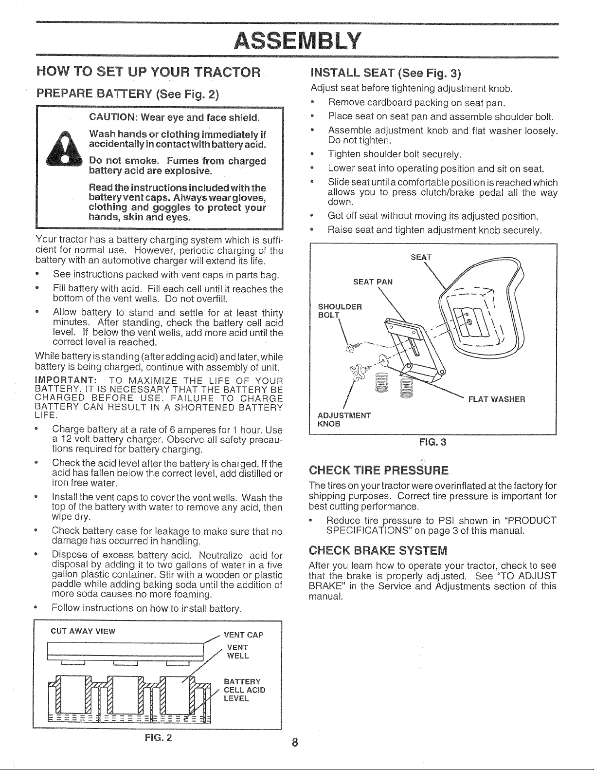
INSTALL SEAT (See Fig. 3)
Adjust seat before tightening adjustment knob.
Remove cardboard packing on seat pan.
o Place seat on seat pan and assemble shoulder bolt.
• Assemble adjustment knob and flat washer loosely.
Do not tighten.
, Tighten shoulder bolt securely.
• Lower seat into operating position and sit on seat.
o Slide seat until acomfortable position is reached which
allows you to press clutch/brake pedal all the way
down.
o Get off seat without moving its adjusted position.
o Raise seat and tighten adjustment knob securely.
SEAT
SEAT PAN
SHOULDER
BOLT
ADJUSTMENT
KNOB
\
FLAT WASHER
FIG. 3
CHECK TIRE PRESSURE
The tires on your tractor were overinflated at the factory for
shipping purposes. Correct tire pressure is important for
best cutting performance.
• Reduce tire pressure to PSI shown in "PRODUCT
SPECIFICATIONS" on page 3 of this manual.
CHECK BRAKE SYSTEM
After you learn how to operate your tractor, check to see
that the brake is properly adjusted. See "TO ADJUST
BRAKE" in the Service and Adjustments section of this
manual.
CUT AWAY ViEW _ VENT CAP
I_ _-_]>._ _ _@/ CELL ACiD
FiG. 2 8
LY
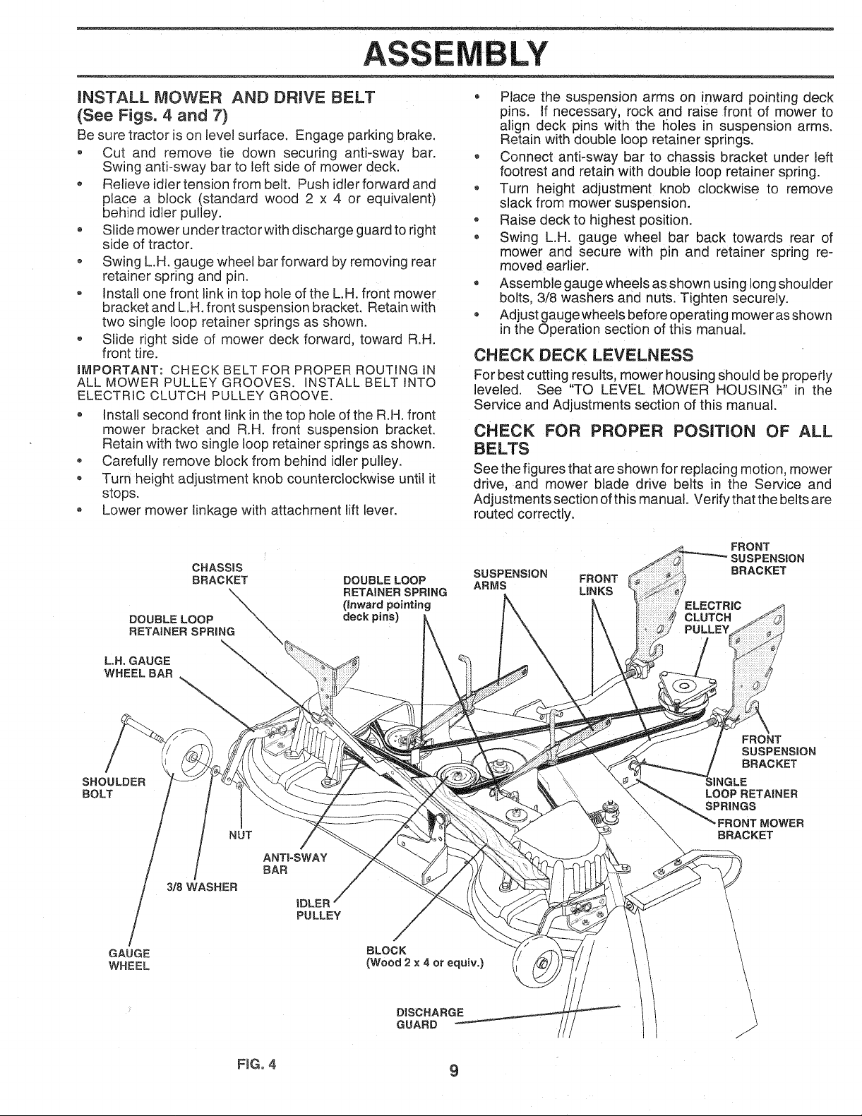
INSTALL MOWER AND DRIVE BELT
(See Figs. 4 and 7}
Be sure tractor is on level surface. Engage parking brake.
o Cut and remove tie down securing anti-sway bar.
Swing anti-sway bar to left side of mower deck.
, Relieve idler tension from belt. Push idler forward and
place a block (standard wood 2 x 4 or equivalent)
behind idler pulley.
® Slide mower under tractor with discharge guard to right
side of tractor.
o Swing L.H. gauge wheel bar forward by removing rear
retainer spnng and pin.
Install one front link in top hole of the L.H. front mower
bracket and L.H. front suspension bracket. Retain with
two single loop retainer springs as shown.
Slide right side of mower deck forward, toward R.H.
front tire.
IMPORTANT: CHECK BELT FOR PROPER ROUTINGIN
ALL MOWER PULLEY GROOVES. INSTALL BELT INTO
ELECTRIC CLUTCH PULLEY GROOVE.
o Install second front link in the top hole of the R.H. front
mower bracket and R.H front suspension bracket.
Retain with two single loop retainer springs as shown.
• Carefully remove block from behind idler pulley.
Turn height adjustment knob counterclockwise unti! it
stops.
o Lower mower linkage with attachment lift lever.
o Place the suspension arms on inward pointing deck
pins. If necessary, rock and raise front of mower to
align deck pins with the holes in suspension arms.
Retain with double loop retainer springs.
- Connect anti-sway bar to chassis bracket under left
footrest and retain with double loop retainer spring.
Turn height adjustment knob clockwise to remove
slack from mower suspension.
® Raise deck to highest position.
• Swing L.H. gauge wheel bar back towards rear of
mower and secure with pin and retainer spnng re-
moved earlier.
o Assemble gauge wheels as shown using long shoulder
bolts, 3/8 washers and nuts. Tighten securely.
® Adjust gauge wheels before operating mowerasshown
in the Operation section of this manual.
CHECK DECK LEVELNESS
For best cutting results, mower housing should be properly
leveled. See "TO LEVEL MOWER HOUSING" in the
Service and Adjustments section of this manual.
CHECK FOR PROPER POSiTiON OF ALL
BELTS
See the figures that are shown for replacing motion, mower
drive, and mower blade drive belts in the Service and
Adjustments section ofthis manual. Verify that the belts are
routed correctly.
DOUBLE LOOP \
RETAINER SPRING
L.H. GAUGE "_
WHEEL BAR
SHOULDER
BOLT
3/8 WASHER
GAUGE
WHEEL
CHASSIS
BRACKET
\
\ \
\
NUT
\
ANTI-SWAY
BAR
iDLER
PULLEY
DOUBLE LOOP
RETAINER SPRING
(inward pointing
deck pins)
BLOCK
(Wood2x4orequiv.)
SUSPENSION FRONT
ARMS LINKS
FRONT
BRACKET
CLUTCH
PULLEY
FRONT
SUSPENSION
BRACKET
LOOP RETAINER
SPRINGS
FRONT MOWER
BRACKET
t
DISCHARGE
GUARD
F_Go4 9

ASSEMBLY
INSTALL BATTERY (See Figs, 5 and 6)
CAUTION: Do not short battery termi-
nares°Before installing battery, remove
metam bracelets, wristwatch bands,
rings, etc°
Positive terminal must be connected
first to prevent sparking from acciden-
tal grounding.
- Lift hood to raised position.
o Be sure battery drain tube has not come loose and is
securely attached to drain in battery tray.
o Lower battery into battery tray with terminals to front of
tractor.
o First connect RED battery cable to positive (+) battery
terminal with hex bolt, flat washer, lock washer and hex
nut as shown. Tighten securely.
o Connect BLACK grounding cable to negative (-) battery
terminal with remaining hex bolt, flat washer, lock
washer and hex nut. Tighten securely.
o Slide the two battery bolts through the terminal guard
and start the wing nuts onto the threads.
° Position terminal guard over battery as shown, lower
battery bolts into key holes and slide square shafts of
battery bolts into slots of key holes.
Tighten wing nuts by hand making sure battery bolts
reman in slots of the key holes inthe battery support.
o Be sure terminal access doors are closed.
Use terminal access doors for:
• Inspection for secure connections (to tighten hard-
ware).
Inspection for corrosion.
® Testing battery.
o Jumping (if required).
o Periodic charging.
FLAT WASHER
/
/ (POSITWE)
/
HEX
/ RED CABLE
HEX BOLT
NEGATIVE)
BLACK CABLE
DRAIN TUBE
ACCESS
DOORS
KEY HOLE
\
\
VENT
CAPS
BATTERY TRAY
FIG. 6
v"CHECKMST
BEFORE YOU OPERATE AND ENJOY YOUR NEW
TRACTOR, WE WISH TO ASSURE THAT YOU RECEIVE
Tt lE BES TPERFORMANCE AND SA TISFA CTION FROM
THIS QUALITY PRODUCT,
PLEASE REVIEW THE FOLLOWING CHECKLIST:
,/ All assembly instructions have been completed.
¢' No remaining loose parts in carton.
v' Battery is properly prepared and charged. (Minimum
1 hour at 6 amps).
,/ Seat is adjusted comfortably and tightened securely.
,/ All tires are properly inflated. (Forshipping purposes,
the tires were overinfiated at the factory).
v" Be sure mower deck is properly leveled side-to-side/
front-to-rear for best cutting results. (Tires must be
properly inflated for leveling).
,/ Check mower and drive belts. Be sure they are routed
properly around pulleys and inside all belt keepers.
v" Check wiring. See that all connections are still secure
and wires are properly clamped.
WHILE LEARNING HOW TO USE YOUR TRACTOR,
PAY EXTRA A TTEN TION TO THE FOL L0 WING IMPOR-
TANT ITEMS:
,/ Engine oil is at proper level.
,/ Fuel tank is filled with fresh clean, regular unleaded
gasoline.
v" Become familiar with all controls - their location and
function. Operate them before you start the engine.
v" Be sure brake system is in safe operating condition.
LOCK WASHER
FtGo 5
10
ERATION
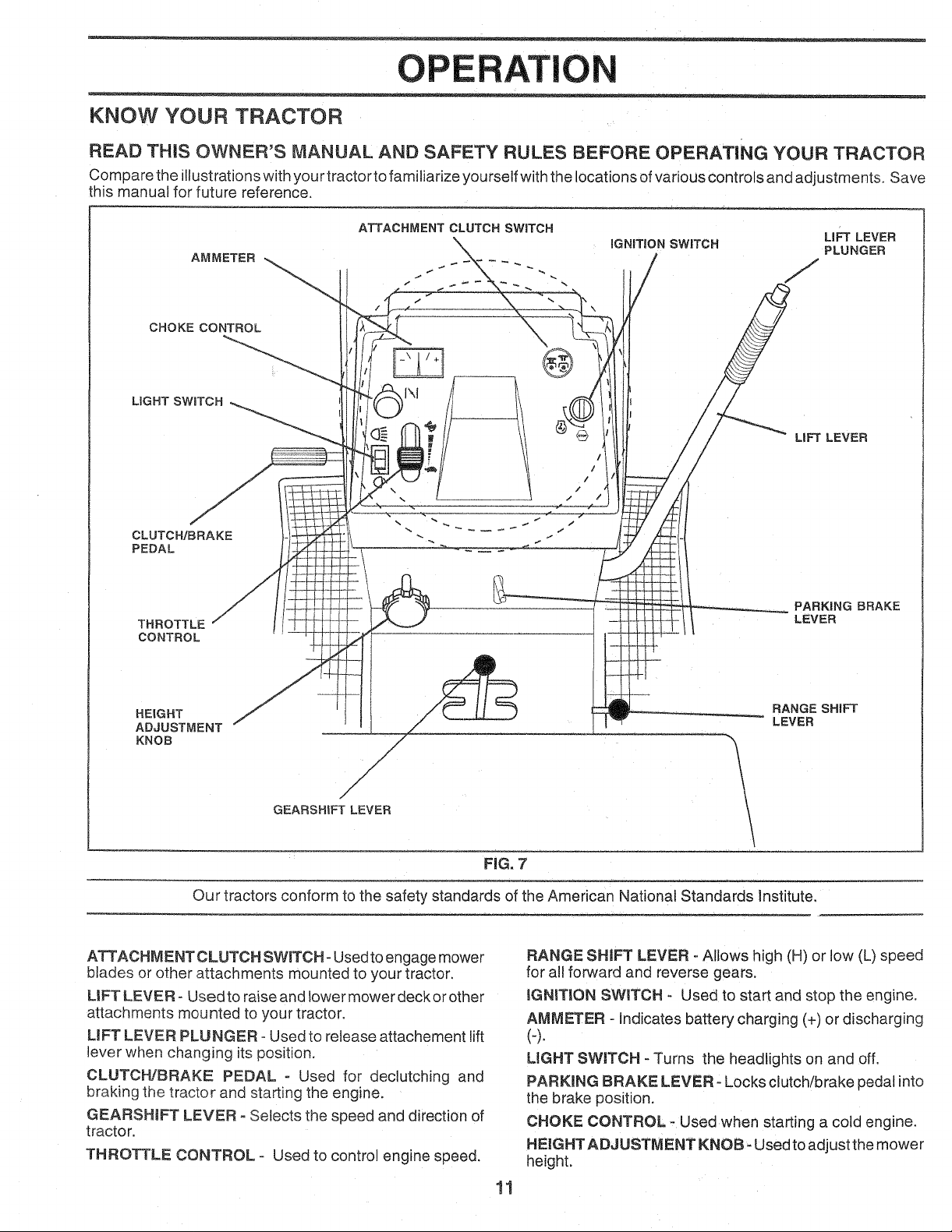
KNOW YOUR TRACTOR
READ THiS OWNER'S MANUAL AND SAFETY RULES BEFORE OPERATING YOUR TRACTOR
Compare the illustrations with your tractor to familiarize yourself with the locations ofvarious controls and adjustments, Save
this manual for future reference,
AMMETER
CHOKE CONTROL
LIGHT SWITCH
CLUTCH/BRAKE
PEDAL
THROTTLE
CONTROL
ATTACHMENT CLUTCH SWITCH
\ iGNiTiON SWITCH
LiFT LEVER
LIFT LEVER
PARKING BRAKE
LEVER
HEIGHT
ADJUSTMENT
KNOB
#
GEARSHIFT LEVER
./
/
/
/
/
/
Our tractors conform to the safety standards of the American National Standards Institute.
ATTACHMENT CLUTCH SWITCH- Used to engage mower
blades or other attachments mounted to your tractor.
UFT LEVER- Used to raise and lower mower deck or other
attachments mounted to your tractor.
LIFT LEVER PLUNGER - Used to release attachement lift
lever when changing its position.
CLUTCH!BRAKE PEDAL - Used for declutching and
braking the tractor and starting the engine.
GEARSHIFT LEVER oSelects the speed and direction of
tractor,
THROTTLE CONTROL - Used to control engine speed.
RANGE SHIFT
LEVER
FIG, 7
RANGE SHIFT LEVER - Allows high (H) or low (L) speed
for all forward and reverse gears.
IGNITSON SWITCH - Used to start and stop the engine.
AMMETER - Indicates battery charging (+) or discharging
(4.
UGHT SWITCH - Turns the headlights on and off.
PARKmNG BRAKE LEVER -Locks clutch/brake pedal into
the brake position,
CHOKE CONTROL - Used when starting a cold engine,
HEIGHT ADJUSTMENT KNOB- Used to adjust the mower
height.
11
OPERATI
= _
The operation of any tractor can resumtin foreign objects thrown into the eyes, which can resumt
in severe eye damage. Always wear safety g_asses or eye shieJds white operating your tractor
or performing any adjustments or repairs, We recommend a wide vision safety mask for over
the spectacles or standard safety glasseso
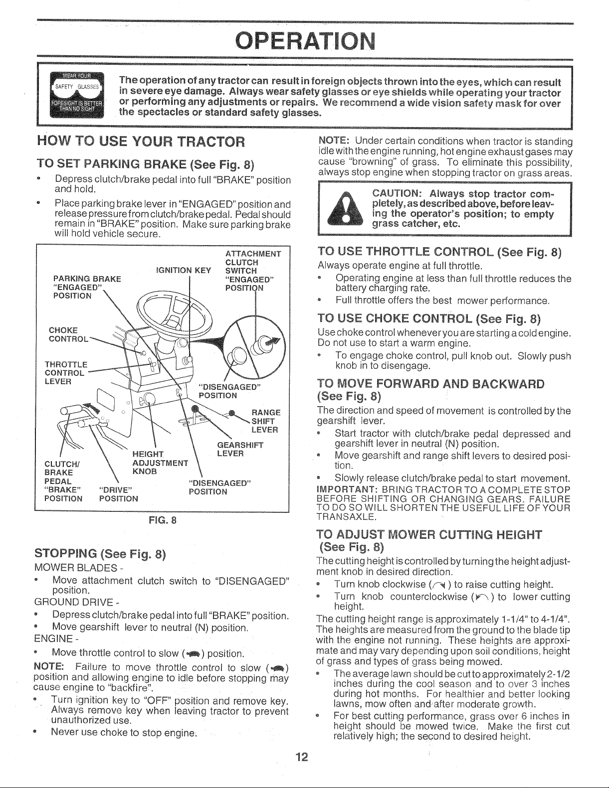
HOW TO USE YOUR TRACTOR
TO SET PARKING BRAKE (See Fig. 8)
• Depress clutch/brake pedal into full "BRAKE" position
and hotd.
Place parking brake lever in "ENGAGED" position and
release pressure from clutch/brake pedal. Pedal should
remain in "BRAKE" position° Make sure parking brake
will hold vehicle secure..
ATTACHMENT
PARKING BRAKE "ENGAGED"
"ENGAGED" POSITION
POSiTiON
CHOKE
THROTTLE
CONTROL
LEVER
CLUTCH/ \ ADJUSTMENT
iGNiTiON KEY SWITCH
HEIGHT LEVER
BRAKE \ KNOB \
PEDAL \ "DaSENGAGED"
"BRAKE .... DRIVE" POSNTION
POSKTJON POSITION
FIG. 8
STOPPING (See Fig, 8)
MOWER BLADES -
- Move attachment clutch switch to "DISENGAGED"
position.
GROUND DRIVE -
, Depress clutch/brake pedal into full "BRAKE" position.
* Move gearshift lever to neutral (N) position.
ENGINE -
, Move throttle control to slow (,_) position,
NOTE: Failure to move throttle control to slow (,_)
position and allowing engine to idle before stopping may
cause engine to "backfire".
o Turn ignition key to "OFF" position and remove key.
Always remove key when leaving tractor to prevent
unauthorized use.
Never use choke to stop engine.
CLUTCH
"DISENGAGED"
POSITION
LEVER
GEARSHIFT
NOTE: Under certain conditions when tractor is standing
idle with the engine running, hot engine exhaust gases may
cause "browning" of grass. To eliminate this possibility,
always stop engine when stopping tractor on grass areas.
CAUTmON: Always stop tractor com-
pletely, as described above, before leavo
ing the operator's position; to empty
grass catcher, etc.
TO USE THROTTLE CONTROL (See Fig, 8)
Always operate engine at full throttle.
, Operating engine at less than full throttle reduces the
battery charging rate.
o Full throttle offers the best mower performance.
TO USE CHOKE CONTROL (See Fig, 8)
Use choke control whenever you are starting acold engine.
Do not use to start a warm engine.
o To engage choke control, pull knob out. Slowly push
knob in to disengage.
TO MOVE FORWARD AND BACKWARD
(See Fig. 8)
The direction and speed of movement _scontrolled by the
gearshift lever.
o Start tractor with clutch/brake pedal depressed and
gearshift lever in neutral (N) position.
- Move gearshift and range shift levers to desired posi-
fion.
° Slowly release clutch/brake pedal to star! movement.
aMPORTANT: BRING TRACTOR TO A COMPLETE STOP
BEFORE SHIFTING OR CHANGING GEARS. FAILURE
TO DO SO WILL SHORTEN THE USEFUL LiFE OF YOUR
TRANSAXLE
TO ADJUST MOWER CUTTING HEIGHT
(See Fig. 8)
The cutting height is controlled by turning the height adjust-
ment knob in desired direction.
o Turn knob clockwise (f-1) to raise cutting height.
o Turn knob counterclockwise (V'_) to lower cutting
height.
The cutting height range is approximately 1-1/4" to 4-1/4".
The heights are measured from the ground to the blade tip
with the engine not running. These heights are approxi-
mate and may vary depending upon soil conditions, height
of grass and types ol grass being mowed.
• The average lawn should be cutto approximately 2-1/2
inches during the cool season and to over 3 inches
during hot months. For healthier and better locking
lawns, mow often and after moderate growth.
o For best cutting performance, grass over 6 inches in
height should oe mowed twice. Make the first cut
relatively high; the second to desired height.
12

OP RAT
TO ADJUST GAUGE WHEELS (See Fig. 9)
® Adjust mower to desired cutting height.
® Lower mower with lift control. Remove rear retainer
spring and clevis pin which secure each gauge wheel.
- Lower gauge wheels to ground. Raise gauge wheels
slightly to align holes in bracket and gauge wheel bar
and insert clevis pins. Gauge wheels should be slightly
off the ground.
Replace retainer springs into clevis pins.
RETAINER
SPRING
CLEVIS PIN
GAUGE WHEEL
GAUGE
WHEEL
TO OPERATE MOWER (See Figs. 7 and 8)
Your unit is equipped with an operator presence sensing
switch. Any attempt by the operator to leave the seat with
the engine running and the attachment clutch engaged will
shut off the engine.
o Select desired height of cut.
o Lower mower with attachment lift control.
o Start mower blades by engaging attachment clutch
control.
o TO STOP MOWER BLADES - disengage attachment
clutch control.
CAUTION: Do not operate the mower _
without either the entire grass catcher,
on mowers so equipped, or the dis-
charge guard in place.
TO OPERATE ON HILLS
CAUTION: Do not drive up or down
hills with slopes greater than 15 and
do not drive across any slope.
• Choose the slowest speed before starting up or down
hills.
o Avoid stopping or changing speed on hills.
• tf slowing is necessary, move throttle control lever to
slower position.
If stopping is absolutely necessary, push clutch/brake
pedal quickly to brake position and engage parking
brake°
Move gearshift lever to I st gear and range shift lever to
low (L) position. Be sure you have allowed room for unit
to roll slightly as you restart movement.
To restart movement, slowly release parking brake and
clutch/brake pedal.
• Make all turns slowly.
TO TRANSPORT
o Raise attachment lift to highest position with attach-
ment lift control,
,, When pushing or towing yourtractor, be sure gearshift
lever is in neutral (N) position.
o Do not push or tow tractor at more than five (5) MPH
NOTE: To protect hood from damage when transporting
your tractor on atruck or atrailer, be sure hood is closed and
secured totractor. Use an appropriate means of tying hood
to tractor (rope, cord, etc.).
BEFORE STARTING THE ENGINE
CHECK ENGINE OIL LEVEL (See Fig. 11)
- The engine in your tractor has been shipped from the
factory, already filled with summer weight oil.
® Check engine oil with tractor on level ground.
Remove oil fill cap/dipstick and wipe clean, reinsert the
dipstick and push it all the way down into the tube, wait
for a few seconds, remove and read oil level. If,
necessary, add oil until "FULL" mark on dipstick is
reached. Do not overfill.
, For cold weather operation you should change oil for
easier starting (See "OIL VISCOSITY CHART" in the
Customer Responsibilities section of this manual).
To change engine oil, see the Customer ResponsibiIF
ties section in this manual.
FiG. 10
OIL FILL CAP/DIPSTICK
RUNNER
_DISCHARGE
GUARD
FIG. 11
13

OPERATmON
ADD GASOUNE
Fill fuel tank. Use fresh, clean, regular unleaded
gasoline. (Use of leaded gasoline will increase carbon
and lead oxide deposits and reduce valve life).
iMPORTANT: WHEN OPERATING IN TEMPERATURES
BELOW 32°F(0°C), USE FRESH, CLEAN WINTER GRADE
GASOLINE TO HELP iNSURE GOOD COLD WEATHER
STARTING.
WARNING: Experience indicates that alcohol blended
fuels (called gasohol or using ethanol or methanol) can
attract moisture which leads to separation and formation of
acids during storage. Acidic gas can damage the fuel
system of an engine while in storage. To avoid engine
problems, the fue! system should be emptied before stor-
age of 30 days or longer. Drain the gas tank, start the
engine and let it run until the fuel lines and carburetor are
empty. Use fresh fuel next season. See Storage Instruc-
tions for additional information. Never use engine or
carburetor charier products in the fuel tank or permanent
damage may occur.
CAUTION: Fill to bottom of gas tank
filler neck. Do not overfiJL Wipe off any
spilled oH or fuel Do not store, spill or
use gasomine near an open flame°
TO START ENGINE (See Fig. 8)
When starting engine for the first time or if engine has run
out of fuel, itwill take extra cranking time to move fuel from
the tank to the engine.
Depress clutch!brake pedal aria set parking brake.
Place gearshift lever in neutral (N) position.
® Move attachment clutch to "DISENGAGED" position.
Pult choke control out to choke (1",1)position for cold
engine start For warm engine start do not use choke
control.
o Move throttle contro to midway between fast (@_)and
slow (_) positions.
Insert key into ignition and turn key clockwise to"START"
position and release key as soon as eng ne starts. Do
not run starter continuously for more than fifteen
seconds per minute. If engine does not start after
several attempts, move throttle control to fast (,@)
position, wait a few minutes and try again.
• When engine starts, slowly push choke control in.
Move throttle control to fast (,_) position.
Allow engine to warm up for a Iew minutes before
engaging drive or attachments.
NOTE: If at a high altitude tabove 3000 feet) or in cold
temperatures (below 32°F} the carburetor fuel mixture
may need to be adjusted for best engine performance See
"TO ADJUST CARBURETOR' m _neService and Adjust-
ments section of this manual.
MOWING TIPS
Tire chains cannot be used when the mower housing
is attached to unit.
- Mower should be properly leveled for best mowing
performance. See "TO LEVEL MOWER HOUSING" in
the Service and Adjustments section of this manual.
- Use the runner on the right hand side of mower as a
guide. The blade cuts approximately an inch outside
the runner (See Fig. 10).
o The left hand side of mower should be used for trim-
ming.
o Drive so that clippings are discharged onto the area
that has been cut. Have the cut area:to the right of the
machine. This wilt result in a more even distribution of
clippings and more uniform cutting.
When mowing large areas, start by turning to the right
so that clippings will discharge away from shrubs,
fences, driveways, etco After one or two rounds, mow
in the opposite direction making left hand turns until
finished (See Fig. 12).
• If grass is extremely tall, it should be mowed twice to
reduce load and possible fire hazard from dried clip-
pings. Make first cut relatively high; the second to the
desired height.
o Do not mow grass when it is wet. Wet grass will plug
mower and leave undesirable clumps. Allow grass to
dry before mowing.
o Always operate engine at full throttle when mowing to
assure better mowing performance and proper dis-
charge of material. Regulate ground speed by select-
ing a low enough gear to give the mower cutting
performance as well as the quaIity of cut desired.
o When operating attachments, select a ground speed
that will suit the terrain and give best performance of
the attachment being used.
FIG. !2
14

CUSTOME RESPONSiBiLiTiES
MAINTENANCE SCHEDULE
FILL INDATES
AS YOU COMPLETE
REGULARSERVICE
Check Brake Operation
Check Tire Pressure
T i Check for Loose Fasteners
Sharpen!ReplaceMower Blades
A
C I LubricationChart
T I Check Battery,Level/Recharge
O Clean BatteryandTerminals
. CheckTransaxle cooling
Adjust Blade Belt(s) Tension
Adjust Motion Drive Belt(s)Tension
Check Engine Oil Level
Change Engine Oil
Clean Air Filter
E!
Clean Air Screen
N
Inspect Muffler/Spark Attester
G
J
Replace Oil Filter (If equipped)
N
Clean Engine Cooling Fins
El
Replace Spark Plug
Replace Air Fitter Paper Cartridge
Replace Fuel Filter
Change more often when operating under a heaw load or in high ambient temperatures.
- Service more often when operating in dirty or dusty conditions.
GENERAL RECOMMENDATIONS
The warranty on this tractor does not cover items that have
been subjected to operator abuse or negligence. To
receive fu!l value from the warranty, operator must maintain
tractor as instructed in this manual.
Some adjustments wit! need to be made periodically to
properly maintain your tractor.
All adjustments in the Service and Adjustments section of
this manual should be checked at least once each season.
Once a year you should replace the spark plug, clean
or replace air filter, and check blades and belts for
wear, A new spark plug and clean air filter assure
proper air-fuel mixture and help your engine run better
and last longer.
SERVICE DATES
3 - tf equipped with oil filter, change oil every 50 hours.
4 - Replace blades more often when mowing in sandy soil.
5 - If equipped with adjustable system.
LUBRICATION CHART
(_)TIE ROD BALL JOINTS
(_) FRONT WHEEL ::::::: ::::: : FRONT WHEEL Q
SECTOR GEAR ENGINE (_)
TEETH
BEFORE EACH USE
o Check engine oil level.
o Check brake operation.
,, Check tire pressure.
Check for loose fasteners.
IMPORTANT: DO NOT OIL OR GREASE THE PIVOT
POINTS WHICH HAVE SPECIAL NYLON BEARINGS.
VISCOUS LUBRICANTS WILL ATTRACT DUST AND DI RT
THAT WILL SHORTEN THE LIFE OF THE SELF-
LUBRICATING BEARINGS. tF YOU FEEL THEY MUST
BE LUBRICATED, USE ONLY A DRY, POWDERED
GRAPHITE TYPE LUBRICANT SPARINGLY.
TRANSAXLE
FLUID
(_SAE 30 MOTOR OiL API. SG
(_) GENERAL PURPOSE GREASE
(_) REFER TO CUSTOMER RESPONSIBILITIES "ENGINE" SECTION
OSPRAY SILICONE LUBRICANT (MOVE BOOTS TO LUBRICATE)
15

l
CUSTOME RESPO LITIES
TRACTOR • The blade can be sharpened with a file or on agrinding
Always observe safety rules when performing any mainte-
nance.
BRAKE OPERATION
If unit requires more than six (6) feet stopping distance at
high speed in highest gear, then brake must be adjusted.
(See "TO ADJUST BRAKE" in the Service and Adjust-
ments section of this manual).
TIRES
,, Maintain proper air pressure in al! tires (See "PROD-
UCT SPECIFICATIONS" on page 3 of this manual).
o Keep tires free of gasoline, oil, or insect control chemi-
cals which can harm rubber.
o Avoid stumps, stones, deep ruts, sharp objects and
other hazards that may cause tire damage.
wheel. Do not attempt to sharpen while on the mower.
• To check blade balance, you will need a 5/8" diameter
steel bolt, pin, or acone balancer. (When using acone
balancer, follow the instructions supptied with bal-
ancer).
o Slide blade on to an unthreaded portion of the steel bolt
or pin and hold the bolt or pin parallel with the ground.
If blade is balanced, it should remain in a horizontal
position. If either end of the blade moves downward,
sharpen the heavy end until the blade is balanced.
NOTE: Do not use a nail for balancing blade. The lobes of
the center hole may appear to be centered, but are not.
CENTER HOLE
BLADE CARE
For best results mower blades must be kept sharp. Re-
place bent or damaged blades.
BLADE REMOVAL (See Fig. 13)
° Raise mower to highest position to allow access to
blades.
• Remove hex bolt, lockwasher and flat washer securing
blade.
o Install new or resharpened blade with trailing edge up
towards deck as shown;
o Reassemble hex bolt, lock washer and flat washer in
exact order as shown.
o Tighten bolt securely (30-35 Ft. Lbs. torque).
IMPORTANT: BLADE BOLT IS GRADE 8 HEATTREATED.
NOTE: We do not recommend sharpening blade- but if you
do, be sure the blade is balanced.
MANDREL
BLADE ASSEMBLY
LOCK WASHER
518" BOLT BLADE
OR PIN j
FIG. ! 4
V-BELTS
Check V-belts for deterioration and wear after 100 hours
and replace if necessary. The belts are not adjustable.
Replace belts if they begin to slip from wear.
TRANSAXLE COOMNG
Keep transaxte free from build-up of dirt and chaff which
can restrict cooling.
CHECK TRANSAXLE OIL LEVEL
(See Fig. 15)
• Block up rear axle securely or use a tractor jack.
o Remove left rear wheel by removing hub bolts.
o Remove filler plug from transaxle. Oil level must be
even with plug threads. If necessary, fill with SAE 30
motor oil, API-SG. Replace filler plug.
o Reassemble wheel to hub.
• For approximate capacity see "PRODUCT SPECIFI-
CATIONS" on page 3 of this manual.
FIG. 13
TO SHARPEN BLADE (See Fig° 14)
Care should be taken to keep the blade balanced. An
unbalanced blade will cause excessive vibration and even-
tual damage to mower and engine.
16
o
o
NG. 15
TRANSAXLE
FILLER PLUG

CUSTO Sl LITIES
BATTERY (See Fig. 16)
Your unit has a battery charging system which issufficient
for normal use However, periodic charging of the battery
with an automotive charger will extend its life,
- Acid solution level in each battery cell should be even
with bottoms of vent wells. Add only distilled or iron free
water if necessary. Do not overfill.
° Keep battery and terminals clean.
Keep battery bolts tight.
Keep vent caps tight and small vent holes in caps open.
o Recharge at 6 amperes for 1 hour.
TO CLEAN BATTERY AND TERMINALS -
Corrosion and dirt on the battery and terminals can cause
the battery to "leak" power.
Remove terminal guard.
• Disconnect BLACK battery cable first then RED bat-
tery cable and remove battery from tractor.
• Wash battery with solution of four tablespoons of
baking sodato one gallon of water. Be careful notto get
the soda solution into the cells.
o Rinse the battery with plain water and dry.
• Clean terminals and battery cable ends with wire brush
until bright.
o Coat terminals with grease or petroleum jelly.
Reinstall battery (See "INSTALL BATTERY" in the
Assembly section of this manual).
CUT AWAY VIEW
NOTE: Although multi-viscosity oils (5W30, !0W30 etc.)
mprove starting in cold weather, these multi-viscosity oils
will result in increased oil consumption when used above
32°F. Check your engine oil level more frequently to avoid
possible engine damage from running low on oil.
Change the oil after the first two hours of operation and
every 50 hours thereafter or at least once a year if the
tractor is not used for 50 hours in one year.
Check the crankcase oil level before starting the engine
and after each eight (8) hours of operation. Tighten oil fill
cap/dipstick securely each time you check the oil level.
TO CHANGE ENGINE OIL (See Figs. 17 and 18)
Determine temperature range expected before oil change.
All oil must meet API service classification SG.
o Be sure tractor is on level surface.
• Oil wil drain more freely when warm.
- Catch oi! in a suitable container,
® Remove oil fill cap/dipstick. Be careful not to allow dirt
to enter the engine when changing oil.
• Remove drain plug.
° After oil has drained corn pletely, replace oil drain plug
and tighten securely.
Refill engine with oil through oil fill dipstick tube. Pour
slowly. Do not overfill. For approximate capacity see
"PRODUCT SPECIFICATIONS" on page 3 of this
manual.
Use gauge on oil fill cap/dipstick for checking level, Be
sure dipstick is in all the way for accurate reading.
Keep oil at "FULL" line on dipstick.
L__q::::C:=:ZT__I j VENTvENTCAP
WELL
BATTERY
CELL ACID
LEVEL
FiG. 16
ENGmNE
LUBRiCATiON
Only use high quality detergent oi rated with API service
classification SG. Select the oil's SAE viscosity grade
according to your expected operating temperature.
SAE VISCOSITY GRADES
:)o 30 ° 60 ° 80 _
-20< - 10° 0' 10' 20' 30' 40 °
qEMPERATURE RANGE AN3 r CiPATED BEFORE NEXT OIL CHANGE
FIG, 17
OIL DRAIN PLUG
\
\
\
OIL FILL
CAP/DIPSTICK
FIG. 18
17
CUSTOME PONSI ILITIES
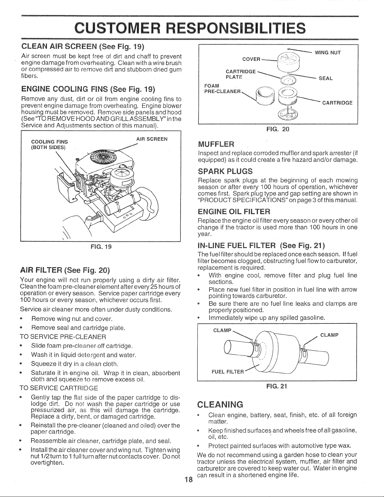
CLEAN AmR SCREEN (See Fig. 19)
Air screen must be kept free of dirt and chaff to prevent
engine damage from overheating. Clean with a wire brush
or compressed air to remove dirt and stubborn dried gum
fibers.
ENGINE COOLING FINS (See Fig, 19)
Remove any dust, dirt or oil from engine cooling fins to
prevent engine damage from overheating. Engine blower
housing must be removed. Remove side panels and hood
(See "TO REMOVE HOOD AND GRILL ASSEMBLY" inthe
Service and Adjustments section of this manual).
COOLING FINS
(BOTH S_DES)
\
A_R SCREEN
\
WING NUT
CARTRIDGE
PLATE _S_'_ SEAL
FOAM _'_J JJ
FIG. 20
MUFFLER
inspect and replace corroded muffler and spark arrester (if
equipped) as it could create afire hazard and/or damage.
SPARK PLUGS
Replace spark plugs at the beginning of each mowing
season or after every 100 hours of operation, whichever
comes first. Spark plug type and gap setting are shown in
"PRODUCT SPECIFICATIONS" on page 3 of this manual.
ENGINE OIL FILTER
Replace the engine oil filer every season or every other oil
change if the tractor is used more than !00 hours in one
year.
FIG. 19
AIR FmLTER (See Fig. 20)
Your engine will not run properly using a dirty air filter.
Clean the foam pre-cleaner element after every 25 hours of
operation or every season. Service paper cartridge every
100 hours or every season, whichever occurs first.
Service air cleaner more often under dusty conditions.
,, Remove wing nut and cover.
• Remove seal and cartridge plate.
TO SERVICE PRE-CLEANER
,, Slide foam pre-cteaner off cartridge.
o Wash it in liquid detergent and water.
• Squeeze it dry in a clean cloth.
, Saturate it in engine oil. Wrap it in clean, absorbent
cloth and squeeze to remove excess oil.
TO SERVICE CARTRIDGE
, Gently tap the flat side of the paper cartridge to dis-
lodge dirt. Do not wash the paper cartridge or use
pressurized air, as this will damage the cartridge.
Replace a dirty, bent, or damaged cartridge.
Reinstall the pre-cleaner (cleaned and oiled) over the
paper cartridge.
® Reassemble air cleaner, cartridge plate, and seal.
,, Install the air cleaner cover and wing nut. Tighten wing
nut 1/2turn to 1fullturn after nut contactscover. Do not
overtighten.
IN-LINE FUEL FILTER (See Fig. 21)
The fue! filter should be replaced once each season. Iffuel
filter becomes clogged, obstructing fuel flow to carburetor,
replacement is required.
o With engine cool, remove filter and plug fuel line
sections.
• Place new fuel filter in position in fuel line with arrow
pointing towards carburetor.
o Be sure there are no fuel line leaks and clamps are
property positioned.
Immediately wipe up any spilled gasoline.
CLAMP
FUEL FILTER
FMGo21
CLEANING
° Clean engine, battery, seat, finish, etc. of all foreign
matter.
• Keep finished surfaces and wheels free of all gasoline,
oil, etc.
• Protect painted surfaces with automotive type wax.
We do not recommend using a garden hose to clean your
tractor unless the electrical system, muffler, air filter and
carburetor are covered to keep water out. Water in engine
can result in a shortened engine life.
18
 Loading...