

Craftsman 917257661 Owner’s Manual

CR/ F /'S
NUMBEI 917.257661
. Assembly
=Operation
- Customer Responsibilities
- Service and Adjustments
=Repair Parts
OWNER'S MANUAL
CAUTION: Read and follow all safety rules and instructions before operating this equipment.
IIIIIIIIIIIIIII IIIIIIIIIIIIIIIIIIII IHIIIIIIIIIIIIIIIIIIIIIIIIIIIIIIII II IIIIIIIIIIIII
Safe Operation Practices for Ride-On Mowers
SAFETY RULES
IMPORTANT: THIS CUTTING MACHINE IS CAPABLE OF AMPUTATING HANDS AND FEET AND THROWING OBJECTS.
FAILURE TO OBSERVE THE FOLLOWING SAFETY INSTRUCTIONS COULD RESULT IN SERIOUS INJURY OR DEATH.
L ,.GENERAL OPERATION
• Read, understand, and follow allinstructionsin the manual
and on the machine before starting
- Only allow responsible adults, who are familiar with the
instructions, to operate the machine
,, Clear the area of objects such as rocks, toys, wire, etc.,
which could be picked up and thrown by the blade
• Besure thearea isctearof other people before mowing. Stop
machine if anyone enters the area
° Never carry passengers
• Do not mow in reverse unlessabsolutely necessary Always
look down and behind before and while backing
• Be aware ofthe mower dischargedirection and do not point
it at anyone Do not operate the mower without either the
entire grass catcher or the guard in place.
• Slow down before turning.
• Never leave a runningmachine unattended. Always turn off
blades, set paWing brake, stop engine, and remove keys
before dismounting°
• Turn off blades when not mowing.
- Stop engine before removing grass catcher or unclogging
chute,,
• Mow only in daylight orgood artificial tighL
• Do not operate the machine while under the influence of
alcohol or drugs
• Watch for traffic when operating near or crossingroadways.
• Use extra care when loading or unloading the machine into
a trailer or truck
II. SLOPE OPERATION
Slopes are a major factor related to ioss,_of.oontroi and tipover
accidents, which can result in severe injury or death. All slopes
require extra caution. Ifyou cannot backup the slopeorifyou feel
uneasy on it, do not mow iL
DO:
• Mow up and down slopes, notacross°
• Remove obstacles such as rocks, trc_ timt:s, etc.
° Watch for holes, ruts, or bumps. Uneven terrain could
overturn the machine. Tailgrass can hide obstac/es.
• Use stow speed° Choose a lowgear sothat you willnot have
to stop or shift while on the slope.
• Follow the manufacturer's recommendations for wheel
weights or counterweights to improve stability_
• Use extra care with grass catchers or other attachments°
These can change the stabilityof the machine°
• Keep all movement on the slopesslow and gradual. Do not
make sudden changes inspeed or direction.
=,.... Avoid starting or stopping on a slop.e if tires lose traction,
disengage the blades and proceed slowly straight down the
slope
DO NOT:
o Donottumons!opesunlessnecessary, andthen,tumslowty
and gradually downhill, if possible
• Do notmow near drop oils, ditches,or embankTnents. The
mower €ould suddenly turnover if a wheel is over the edge
of a cliffor ditch, or if an edge caves in.
. Do not mow on wet grass. Reduced traction could cause
sliding.
• Do not tryto stabilize the machine by puttingyourfoot onthe
ground.
• Do not use grass catcher on steep slopes.
IlL CHILDREN
Tragic accidents can occur if the operator [s not alert to the
presence of children. Children are often attracted tothe machine
and the mowing activity Never assume that children will remain
where you lastsaw them
° Keep childrenoutofthe mowing area and under thewatchful
care ofanother responsible adulL
• Be alert and turn machine off if children enter the area,
° Before and when backing, look behind and down for small
children°
. Never carry children They may fall off and be seriously
injured or interfere withsafe machine operation
- Never allow children to operate the machine
° Use extra care when approaching blind comers, shrubs,
trees, or other objects that may obscure vision.
IV. SERVICE
° Use extracare inhandlinggasoIine and other fuels. They are
flammable and vaporsare exptosiveo
Use onlyan approved container
Never remove gas cap or add fuel with the engine
running. Allow engine to coolbefore refueling. Do not
smoke.
- Never refuel the machine indoors
Never storethe machine or fuel container inside where
there isan open flame, such as a water heater.
° Never runa machine inside a closed area.
• Keep nutsand belts, especially blade attachment bolts, tight
and keep equipment in goodcond_on.
• Never tamper with safety devices. Check their proper
operation regularly
- Keep machinefree ofgrass, teaves, or other debrisbuild-up
Clean oil or fuel spillage Allow machine to cool before
storing.
° Stop and inspect the equipment if you strike an object.
Repair, if necessary, before restarting.
° Never make adjustments or repairswith the engine running.
• Grass catchercomponents aresubject to wear, damage, and
deterioration, which could expose moving parts or allow
objects to be thrown. Frequently check components and
replace with manufacturer's recommended parts,when nec-
essary..
• Mower blades are sharp and can cut. Wrap the blade(s) or
wear gloves, and use extra caution when servicing them.
- Check brake operation frequently. Adjust and service as
required.
tant safety precautions. It means J
J tj_ L.ook for this symbol to point out [mpor- I
CAUTION!!! BECOME ALERT_.!! YOUR J
SAFETY iS INVOLVED. J
IIIIIII II II I IllU III IJlllll III IIIII
CAUTION: Always disconnect spark
plug wire and place wire where it cannot
contact spark plug in order to prevent
accidental starting when setting up,
transporting, adjusting or making
repa,rs.
L I IIU LI I IILIIIILIIIII : Illl II _ J_lll

CONGRATULATIONS on your purchase of a Sears
tractor. It has been designed, engineered and manufac-
tured to give you the best possible dependability and
pedormance.
Should you experienceany problemyou cannoteasily
remedy, please contact your nearest Sears Service Cen-
ter/Department. We have competent, well-trained tech-
nicians and the proper tools to service or repair this unit.
Piease read and retain this manual. The ins|_ctions will
enable you to assemble and maintain your unit properly,.
Always observe the "SAFETY RULES"°
MODEL
NUMBER
917o257661
SERIAL
NUMBER
DATE OF PURCHASE
THE MODELAND SERIAL NUMBERSWlLL BE FOUND
ON A PLATE UNDER THE SEAT.
YOU SHOULD RECORD BOTH SERIAL NUMBERAND
DATE OF PURCHASE AND KEEP IN A SAFE PLACE
FOR FUTURE REFERENCE.
MAINTENANCE AGREEMENT
A Sears maintenance agreement is available on this prod-
uct. Contact your nearest Sears store for details.
CUSTOMER RESPONSIBILITIES
. Read and observe the safety rules.
. Followaregularschedulein maintaining, caring forand
using your unit.
,, Follow the instructions under "Customer Responsibili-
ties" and "Storage" sections of this owner's manual.
................. _..................... ,, ,,, _ Ullllll i ,11 iiiii i ii i i
PRODUCT SPECIFICATIONS
HORSEPOWER; 15.5
GASOLINE CAPACITY 3.5 GALLONS
AND TYPE: UNLEADED REGULAR
OIL TYPE (API-SF/SG): SAE I 0W.30 (above 32"F)
OIL CAPACITY: W/FILTER: 4.5 PINTS
SPARK PLUG: CHAMPION RC12YC
(GAP; .030_)
"vALVE CLEARANCE: INTAKE: .0015"..003(Y'
GROUND SPEED (MPH): FORWARD; 5.62
!
TIRE PRESSURE: FRONT: 14 PSI
CHARGING SYSTEM: 3 AMPS BATTERY
BLADE BOLT TORQUE: 30-35 FTo LBSo
WARNING: This unit is equipped with an internalcombus-
tion engine and should not be used on or near any unim-
proved forest-covered, brush-covered or grass.covered
land unless the engine's exhaust system is equipped with
a spark arrester meeting applicable local or state taws {if
any). If a spark an'ester _sused, itsnouldbe maintained =n
effective workingorder by the operator.
In the state of California the above is required by law
(Section 4442 of the California Public Resources Code),
Other states may have similar laWS. Federal lawsapp_ on
federal lands. A spark arrester for the muffler is available
through your nearest Sears Authorized Service Center
(See REPAIR PARTS section of thismanual).
SAE 5W_30 (below 32=F)
W/O FILTER: 4.0 PINTS
EXHAUST: ,0020". o0035"
REVERSE: 2.4
REAR: 10 PSi
5 AMPS HEADLIGHTS
:
LIMITED TWO YEAR WARRANTY ON ELECTRIC START RIDING EQUIPMENT
For two (2) years from the date of purchase, if this ridingequipment is maintained, lubricated and tuned up according to the
instructions in the owner's manual, Sears ,,viiirepair or replace, free of charge, any parts found to be defective in matedal or
workmanship.
This Warranty does not cover:.
• Expendable items which become worn during normal use, such as blades, spark plugs, air cleaners and belts.
• Tire replacement or repair caused by punctures from outside objects, such as nails, thorns,stumps, or glass.
• Repairs necessary because of operator abuse, negfigence, Tmproper storage or accident or the failure to maintain the
equipment according to the instructionscontained in the owner's manual.
, Riding equipment used for commercial or rental purposes.
LIMITED 90 DAY WARRANTY ON BATTERY
For ninety (90) days from date of purchase, if any battery inctuded with this riding equipment proves defective in material or
workmanship and our testingdetermines the battery willnot hold a charge, Sears willreplace the battery at no charge.
WARRANTY SERVICE IS AVAILABLE BY RET1JRNING THE RIDING EQUIPMENT TO THE NEAREST SEARS SERVICE
CENTER/DEPARTMENT 1NTHE UNITED STATES.
This Warranty gives youspec_,clegal rights,andyoumayalso have otherrights whichmay va_,from statetostate°
SEARS, ROEBUCK AND CO. D/817 WA, HOFFMAN ESTATES, ILLINOIS 60179
3
S AF_-TY RULES ........................................................... 2
PRODUCT SPECIRCATIONS ...................................... 3
CUSTOMER RESPONSIBILITIES ..................... 3, 16-19
WARRANTY ..: ................................................. ;. ........... 3
TRACTOR ACCESSORIES ........................... ._........... ;. 5
ASSEMBLY ............................................................. 7-10
OPERATION ......................................................... 11-15
INDEX
A
Accessories ........................................... 5
Adjustments:
Brake ............................................ 22
Carburetor .................................... 26
Mower
Front-To-Back ......................... 21
Side-To-Side ............................ 21
Throttle Control Cable .................. 26
Air Filter, Engine...................................... 19
Ait Screen, Engine ..................................18
Assembly ............................................. 7-10
B
Battery,_,
Charging .......................................... 8
Cleaning ....................................... t7
installation ...................................... 9
Levels .......................................... 8,17
Preparation .................................... 8
Starting with Weak Battery.......... 24
Storage ......................................... 27
Terminals ..................................... 17
Bell:
Motion Drive
Removal/Replacement ............ 23
Mower Belt(s)
Removal/Replacement ............. 22
Blade:
Sharpening .................................... 17
Replacement ................................ 17
Brake Adjustment ................... ............... 22
C
Carburetor Adjustment ........................ 26
Controls, Tractor .................................. 11
Customer Responsibilities.................16-19
Engine:
Air Filter..................................... 19
Air Screen .................................. 18
Cooling Fins ............................. 19
Engine Oil ........................... 13,18
Fuel Filter.................................. 19
Spark Plug(s) ........................... 19
Tractor:.
Battery ...................................... 17
Blade ......................................... 17
Lubncation Chart ....................... 16
Maintenance Schedule ............ 16
Tire Care .......................... 8,t7,27
Transmde ................................. 18
Cuffing Height, Mower ......................... 12
Electrical:
tntedocksand Relays ................... 25
Schematic .................................... 31
Wiring Diagram ............................ 32
Engine:
Air Filter......................................... 19
Air Screen ..................................... 18
Cooling Fins.................................. 19
Oil Change ................................... 18
Oil Level ........................................ t8
Oil Type ................................... 13,18
Preparation .................................. 13
Repair Parts ............................ 50-55
Starting ........................................... 14
Storage ........................................... 27
Filter:.
Air Filter.......................................... t9
Fuel............................................... 19
Fuel:
Type ............................................. 14
Storage ........................................ 27
Fuse ....................................................... 25
Hood Removal_/InstaUation................... 25
LevelingMower Deck ......................... 21
Lubrication:
Chart ............................................ 16
Engine.......................................... t8
Maintenance Schedule ........................ t6
Mower:
Adjustment, Front-to-Back ............. 21
Adjustment, Side.to-Side .............. 21
Blade Replacement ....................... 17
Blade Sharpening ........................ 17
Cutting Height .............................. 12
Installation .................................... 20
Operation ....................................... 13
Removal ....................................... 20
Mowing TTps........................................ 15
Muffler ................................................. 19
Spark Arraster........................... 3,40
MAII'_ENANCE SCHEDULE ..................................... 16
SERVICE AND ADJUSTMENTS ........................... 20-26
STORAGE ................................................................... 27
TROUBLESHOOTING .......................................... 26-29
REPAIR PARTS - TRACTOR .......;...................... 32-47
REPAIR PARTS - ENGINE ............. +.................... 50-55
PARTS ORDERING/SERVICE ............... BACK COVER
E
Oil:
Cold Weather Conditions ........ 12,18
Engine ......................................... 18
Storage ........................................ 27
Operation ....................................... 11-15
Operating Mower ................................. 13
Options:
Accessories .................................... 5
Spark An*ester............................. 3,40
O
P
Parking Brake ................................ 11-12
Parts Bag .................. :........................... 6
Parts, Reptacement/RP.pair ............ 32-47
F
Product Specirmations........................... 3
R
Repair Parts ................................... 32-47
S
Safety Rules .......................................... 2
Seat ....................................................... 8
H
L
M
Service and Adjustments ............... 20-26
Carburetor ..................................... 26
Pus++............................................. 25
Hood RemovaLflnstaJlation........... 25
Motion Drive Belt
Removal/Replacement ............ 23
Mower Belt(s)
Removal/Replacement ............ 22
Mower Adjustment
Front-to-Back .......................... 21
Side-to-Side ............................ 21
Mower Remova_nstaJlation ......... 20
13reCare ............................... 8,17,27
Slope Guide Sheet .............................. 59
Spark Plug(s) ........................................ 19
Specifications ......................................... 3
Sta_ng the Engine ............................. 14
Steering Wheel .................................. 7,24
Stopping the Tractor ............................ 12
Storage ................................................ 27
T
Throttle Control Cable Adjustment ...... 26
Tires............................................ 8,17,27
Trouble Shooting Chart .................. 28-29
Transaxle ............................................ 18
W
Warranty ................................................. 3
Wiring Oiagram ................................... 32
4
Wiring Schematfc ............................... 31
i,ii, ,, i,i .......... ill ll.... i,,_ •
ACCESSORIES AND ATTACHMENTS
,m,,, H ..................................... III " III L' _
These accessories and attachments were available throughmost Sears retail outlets and service centers when the tractor was putchased_
Most Sears stores can order these items foryou when you provide the model number of your tractor.
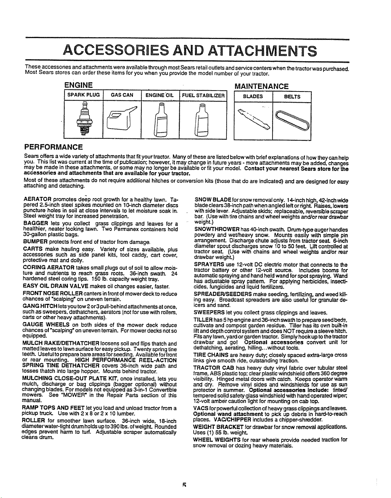
ENGINE
SPARK PLUG GAS CAN ENGINE*OIL FUEL STABlUZER
PERFORMANCE
Sears offers a wide variety ofattachments that fityour tractor° Many of these are listed below withbrief explanations of how they can help
you. This list was current at the time of publication; however, it may change in future years - more attachments may be added, changes
may be made in these attachments, or some may no longer be available or fit your model. Contact your nearest Sears store for the
accessories and attachments that are available for your tractor.
Most of these attachments do not require additional hitches or conversion kits (those that do are indicated) and are designed for easy
attaching and detaching,
MAINTENANCE
BLADES BELTS
AERATOR promotes deep root growth for a healthy lawn. Ta-
pered 2o5-inchsteel spikes mounted on 10-inch diameter discs
puncture holes in soil at close intervals to let moisture soak in.
Steel weight tray for increased penetration.
BAGGER lets you collect grass clippings and leaves for a
healthier, nearer looking lawno Two Permanex containers hold
30-gallon plastic bags.
BUMPER protects frontend of tractor from damage_
CARTS make hauling easy° Variety of sizes available, plus
accessories such as side panel kits, tool caddy, cart cover,
protective mat and dolly_
CORING AERATOR takes small plugs out of soilto allow mois-
ture and nutrients to reach grass roots. 36_inch swath. 24
hardened steel coring tips. 150 lbocapacity weighttray.
EASY OIL DRAIN VALVE makes oilchanges easier, faster
FRONT NOSE ROLLER canters in front ofmower deck to reduce
chances of "scalping"on uneven terrain,
GANG HITCH letsyou tow2 or3 pull-behindattachments atonce,
suchas sweepers, dethatchers, aerators (notfor use with rollers,
carts or other heavy attachments).
GAUGE WHEELS on both sides of the mower deck reduce
chances of "scalping"on uneven terrain. Formower decks notso
equipped,
MULCH RAKEiDETHATCHER loosenssoil and ftips thatch and
matted leaves to lawn surface for easy pickup° Twenty springline
teeth. Usefuttoprepare bare areas forseeding. Available for front
or rear mounting. HIGH PERFORMANCE REEL-ACTION
SPRING TINE DETHATCHER covers 36-inch wide path and
tosses thatch into large hopper. Mounts behind tractor
MULCHING CLOSE.OUT PLATE KIT, once installed, lets you
mulch, discharge or bag clippings (bagger optional) without
changing blades. For models not equipped as 3-in.1 Convertible
mowers. See "MOWER" in the Repair Parts section of this
manual.
RAMP TOPS AND FEET letyou load and unload tractorfrom a
pickup truck_ Use with2 x 8 or 2 x 10 lumber.
ROLLER for smoother lawn surface. 36-inch wide, 18-inch
diameterwateF-tight drumholdsup to390 Ibs.ofweighL Rounded
edges prevent harm to turf. Adjustable scraper automatically
cleans drum.
SNOW BLADE for snow removal only. 14-inch high, 42-inchwide
blade clears38-inch pathwhen angled left ordghL Raises, lowers
withside lever. Adjustableskids; replaceable, reversible scraper
bar. (Use withtirechains and wheel weights and/or reardrawbar
weight.)
SNOWTHROWER has40.inch swath. Drum-type auger handles
powdery and wet/heavy snow° Mounts easily with simple pin
arrangement. Discharge chute adiusts from tractor seal 6-inch
diameter spoutdischarges snow 10 to 50 feeL Liftcontrolledat
tractor seat. (Use with chains and wheel weights and/or rear
drawbar weight.)
SPRAYERS use 12-volt DC electric motor that connects to the
tractor battery or other 12-vott source. Includes booms for
automaticspraying and hand heldwand for spot spraying. Wand
has adjustable spray pattern. For applying herbicides, insecti-
cides, fungicides and liquidfertilizers.
SPREADER/SEEDERS make seeding, fertilizing, and weed kiik
!ng easy. Broadcast spreaders are also useful for granular de..
=cersand sand°
SWEEPERS tetyou collectgrass clippings and leaves.
TILLER has 5 hp engine and 36-inch swath toprepare seedbeds,
cultivate and compostgarden residue° Tiller has its own built.in
lilt anddepth controlsystem anddoesNOT require asleeve hitch,
Fitsany tawn, yard orgardentractor, Simplyhook uptothetractor
drawbar and go! Optional accessories convert unit for
dethatching, aerating, hilling...without tools.
TIRE CHAINS are heavy duty; closely spaced extra-large cross
links give smooth ride, outstanding traction.
TRACTOR CAB has heavy duty vinyl fabric over tubular steel
frame, ABS ptastictop; clear plastic windshield offers360 degree
visibility. Hinged metal doors with catch. Keeps operatorwarm
and dry. Remove vinyl sides and windshields for use as sun
protector in summer. Optional accessories include; tinted/
tempered solid safety glasswindshieldwith hand operatedwiper;,
12-volt amber caution light for mounting on cab top.
VACS forpowerfulcollection of heavy grass clippingsand leaves.
Optional wand attachment to pick up debris in hard-to-reach
places. VACJCHIPPER includes achipper-shredder.
WEIGHT BRACKET for drawbar forsnow removal applications.
Uses (1) 55 tboweight.
WHEEL WEIGHTS for rear wheels provide needed traction for
snow removal or dozing heavy materials.
" .......................................................... Hill, ii ill, i,H_
CONTENTS OF HARDWARE PACK
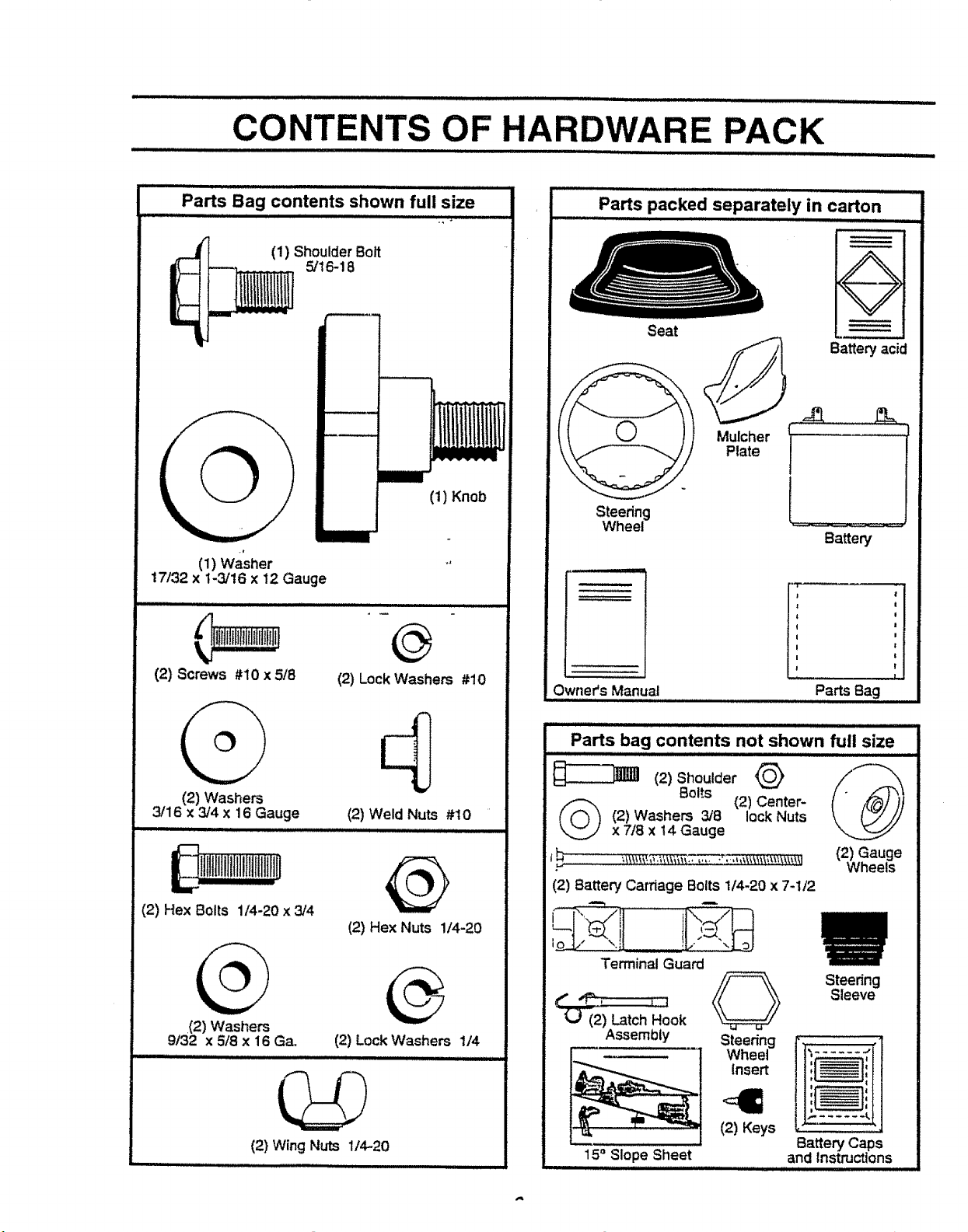
Parts Bag contents shown full size
(1) Shoulder Bolt
5/16-18
_--]
i
Illlll
(1) Washer
17/32 x 1-3/16 x 12 Gauge
@
(2) Screws #10 x 5/8
(2) Lock Washers #10
(1) Knob
Parts packed separately in carton
ill iii mll,llllll,
Steering
Wheel _ '
Owner's Manual
Seat
i,ii iii i i
f.
Battery acid
Plate
Mulcher t
Battery
J'i
J
Parts Bag
(2) Washers
3/16 x 3/4 X 16 Gauge
i!illtlllllfltlllllltltlln
(2) Hex Bolts 1/4-20 x 3/4
,(2)Washers
9/32 x 5/8 x 16 Ga.
(2) Wing Nuts 1/4--20
(2) Weld Nuts #10
(2) Hex Nuts 1/4-20
(2) Lock Washers 1/4
lllll i i
Parts bag contents not shown full size
Bolts (2) Center-
(_ (2) Washers 3/8 lock Nuts
. Wheels
(2) Battery Carnage Bolts 1/4-20 x 7-1/2
(2)ShoulderQ @
x 7/8 x t4 Gauge
_I !!.:."_:,t_oJ
Terminal Guard
Steering
Sleeve
(_ (2) Latch Hook
Assembly
15° Slope Sheet
Steer{ng
Wheel
Insert
(2) Keys
It':,...... fl,,
Battery Caps
and instructions
LY
:7 II'MII I1'1' I L I'1 ,i, ,,_1,,i, i
Your new tractor has been assembled at the factory with exception of those parts left unassembled for shippingpurposes.
To ensure safe and proper operation of your tractor, allparts and hardware you assemble must be tightened securely° Use
the correct tools as necessary to insure proper tightness.
TOOLS REQUIRED FOR AssEMBLY
A socket wrenchset will make assembly easier. Standard
wrench sizes are listed,
(1) 9/16 "_wrench (2) 7/16" wrench
(1) 1/2= wrench (1) 314" socketw/drive
Utility knife ratchet
Tire pressure gauge (1) Phillips Screwdriver
When right and left hand is mentioned in this manual, it
means when you are in the operating position (seated
behind the steering wheel).
TO REMOVE TRACTOR FROM CAR-
TON
UNPACK CARTON
- Remove all accessible loose parts and parts cartons
from carton (See page 6).
. Cut, from top to bottom, along lines on all four comers
of carton, and lay panels flat,
o Check for any additional loose parts or cartons and
remove.
BEFORE ROLLING TRACTOR OFF SKID
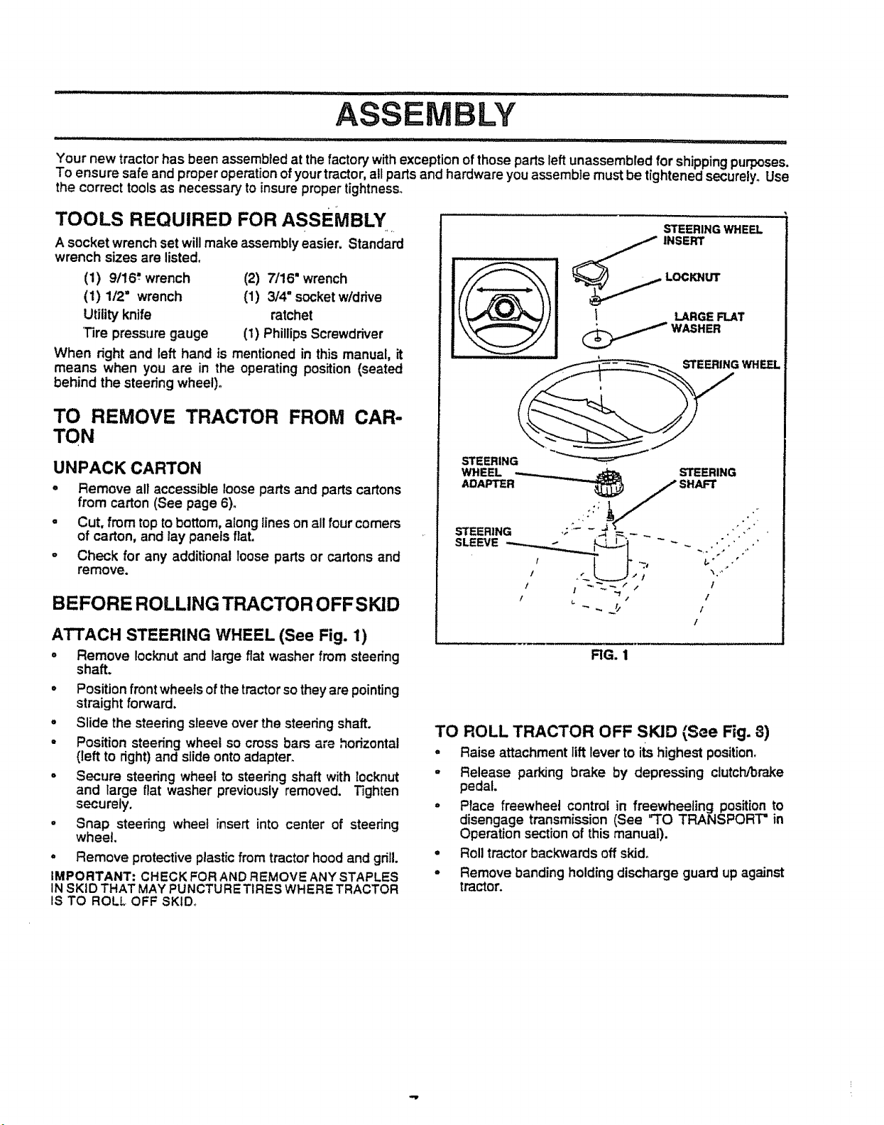
ATTACH STEERING WHEEL (See Fig. 1)
° Remove Iocknut and large flat washer from steering
shaft.
o Position front wheelsof thetractor so theyare pointing
straight forward.
° Slide the steering sleeve overthe steedng shaft.
- Position steering wheel so cross bars are horizontal
(left to right)and slide onto adapter.
- Secure steedng wheel to steering shaft with locknut
and large flat washer previously removed. Tighten
securely.
o Snap steering wheel insert into center of steering
wheel.
° Remove protective plastic from tractor hood and grill.
IMPORTANT: CHECK FOR AND REMOVE ANY STAPLES
IN SKID THAT MAY PUNCTURETIRES WHERE TRACTOR
IS TO ROLL OFF SKID_
STEERING WHE_
1 LARGEFLAT
,_,_ WASHER
STEERING WHEEL
STEERING
WHEEL STEERING
/ I ~%_/ / f
I ,_ .,' t
/
RG. 1
TO ROLL TRACTOR OFF SKID {See Fig. 8)
° Raise attachment lift lever to its highest position.
o Release parking brake by depressing clutch/brake
pedal.
• Place freewhee! control in freewheeling position to
disengage transmission (See "TO TRANSPORT = in
Operation section of this manual).
° Rolltractor backwards off skid,
• Remove banding holding discharge guard up against
tractor.
HOW TO SET UP YOUR TRACTOR
PREPARE BATTERY (See Fig. 2)
CAUTION: Wear eye and face shield.
Wash hands or clothing immediately if
accidentally in contact with battery acid,
Do"not smoke, Fumes from charged
battery acid are explosive,
Read the instructions included withthe
battery vent caps, Always wear gloves,
clothing and goggles to protect your
hands, skin and eyes.
IIII iiiiiiii I L I UII !UII I I iiii iiiii i I
Your tractor has a battery chargingsystem which is suffi-
cient for normal use. However, periodic charging of the
batter,,/with an automotive charger wiltextend ffs life.
• See instpJctionspacked with vent caps in parts bag.
• Fill batter,! withacid° Fill each cell untilit reaches the
bottom of the vent wells. Do not overt'ilL
• Allow battery to stand and settle for at least thirty
minutes° After standing, check the battery cell acid
level. If below the vent wells, add more acid until the
correct level is reached.
While battery is standing (after adding acid) and later, while
battery is being charged, continuewith assembly of tractor,
IMPORTANT: TO MAXIMIZE THE LIFE OF YOUR
BATTERY, tT IS NECESSARY THAT THE BATTERY BE
CHARGED BEFORE USE,= FAILURE TO CHARGE
BATTERY CAN RESULT tN A SHORTENED BATTERY
LIFE,
° Charge batter,/at a rate of 6 amperes for i hour_Use
a 12 volt battery charger. Observe all safety precau-
tions required for battery charging.
° Check the acid level after the battery ischarged, if the
acid has fallen below the correct level, add distilled or
iron free water.
° Install the vent caps tocover the vent wells. Wash the
top of the battery with water to remove any acid, then
wipe dry.
- Check battery case for leakage to make sure that no
damage has occurred in handling.
• Dispose of excess battery acid. Neutralize acid for
disposal by adding it to two gallons of water in a five
gallon plastic container. Stir with a wooden or plastic
paddle while adding baking soda until the addition of
more soda causes no more foaming.
• Follow instructions on how to install battery,
CUT AWAY VIEW VENT CAP
VENTWELL
BATTERY
CELL ACiD
LEVEL
_ _ o
LY
=,Hm,, = ..................................... !,!! ! .... i I I II !! IIl_L'll , ,...........
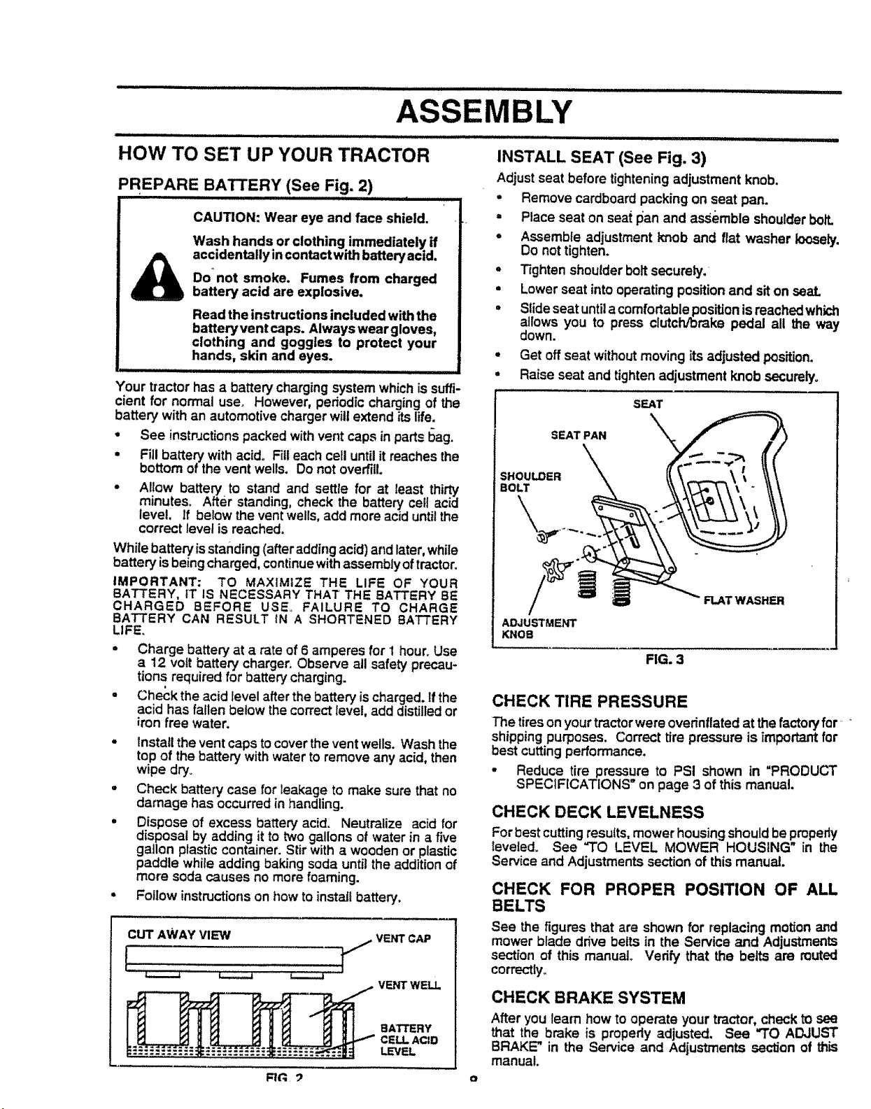
INSTALL SEAT (See Fig. 3)
Adjust seat before tighteningadjustment knob.
= Remove cardboard packing on seat pan.
. Place seat on seat pan and assemble shoulderbolt.
o Assemble adjustment knob and flat washer loosely.
Do not tighten.
° T_ghtenshoulder boltsecurely.
• Lower seat into operating positionand sit on seal
= Slide seat untila comfortable positionis reachedwhk:h
allows you to press clutch/brake pedal all the way
down.
. Get off seat withoutmoving its adjusted position.
° Raise seat and tighten adjustment knob securely°
SEAT
SEAT PAN
SHOULDER
BOLT
FLATWASHER
ADJUSTMENT
KNOB
FIG. 3
CHECK TIRE PRESSURE
The tires on your tractor were overinflated at the factory for ....
shipping purposes. Correct tire pressure is important for
best cuttingperformance.
• Reduce tire pressure to PSI shown in "PRODUCT
SPECIFICATIONS on page 3 of this manual.
CHECK DECK LEVELNESS
Forbest cutting results, mower housing shouldbe pmpedy
leveled. See "TO LEVEL MOWER HOUSING" in the
Service and Adjustments section of this manual.
CHECK FOR PROPER POSITION OF ALL
BELTS
See the figures that are shown for replacing motion and
mower blade drive belts in the Service and Adjustments
section of this manual. Verify that the belts are muted
correctly.
CHECK BRAKE SYSTEM
After you learn how to operate your tractor, check to see
that the brake is propedy adjusted. See "TO ADJUST
BRAKE" in the Service and Adjustments section of this
manual.
i
........................ i, ii II_IL I n : I I,,lll,lll,I,I, ,,,I ,//11 I.......................
ASSEMBLY
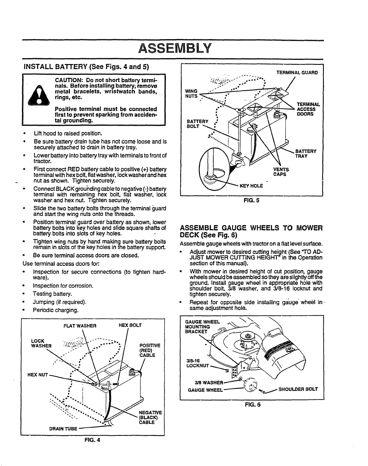
INSTALL BATTERY (See Figs. 4 and 5)
CAUTION: Do not short battery termi-
nals. Before installin_l battery; remove
metal bracelets, wristwatch bands, ....
rings, etc.
Positive terminal must be connected
first to prevent sparking from acciden-
tal grounding.
, Lift hoodto raised position,
° Be sure battery drain tube has not come looseand is
securely attached to drainin battery tray.
° Lower battery into battery traywith terminalstofront of
tractor.
- Firstconnect RED battery cable topositive(+) battery
terminalwithhex bolt, fiatwasher, lockwasherand hex
nut as shown. Tighten securely.
• Connect BLACK groundingcable tonegative (_ battery
terminal with remaining hex bolt, fiat washer, lock
washer and hex nut. Tighten securely.
° Slide the two battery bolts through theterminal guaKI
and start the wing nutsonto the threads.
o Position terminal guard over battery as shown, lower
battery boltsinto key holes and slide square shafts of
battery bolts into slotsof key holes.
° T_ghtenwing nuts by hand making sure battery bolts
remain inslotsof the key holes in the battery support.
,' Be sure terminal accessdoors are closed.
Use terminal access doorsfor:.
° Inspection for secure connections (to tighten hard-
ware).
° Inspection for corrosion.
° Testing battery.
° Jumping (if required),
- Periodic charging.
i iiii1,,, !
TERMINAL GUARD-
WING
NUTS
TERMINAL
: ACCESS
DOORS
BATTERY
BOLT
BATTERY
TRAY
VENTS
CAPS
HOLE
FIG. 5
ASSEMBLE GAUGE WHEELS TO MOWER
DECK (See Fig. 6)
Assemble gauge wheels withtractor ona fiat levelsurface°
° Adjust mower to desired cuttingheight (See "TO AD-
JUST MOWER CUTTING HEIGHT" in the Operation
section of this manual).
° With mower in desired height of cut position, gauge
wheels shouldbeassembled sotheyareslightlyoffthe
ground. Install gauge wheel in appropriate hole wP,_h
shoulder bolt, 3/8 washer, and 3/8-16 Iocknut and
tighten securely.
• Repeat for opposite side instaiiing gauge_wheel in-
same adjustment hole.
FLAT WASHER HEX BOLT
LOCK i: ....
WASHER POSITIVE
,"" * CABLE
Ha
•
it
NEGATIVE
(BLACK)
CABLE
DRAIN TUBE
RG. 4
GAUGE WHEEL
MOUNTING
BRACKET
3/8-16
SHOULDER BOLT
RG. 6

ASSEMBLY .................
,,,,,,, ,, ,,,, ,,,,, ,,,
INSTALL MULCHER PLATE
(See Figs. 7A & 7B)
• rInstall two latch hooks to mulcher plate usingscrew,
washer, lock washer, and weld nutas shown.
NOTE: Pre-assemble weld nutto latch hook by inserting]"
weld nut from the top with hookpointing down.
• Tighten hardware securely_
• Raise and I_otddeflectorshield in uprightposition.
o Place front of mulcher plate over front of mower deck
opening and slide into place, as shown.
• Hook front latchinto holeon front of mower deck.
• Hook rear latch intohole on back of mower deck.
CAUTION: Do not remove discharge !
guard from mower, Raise and hold
guard when attaching mulcher plate
LATCH
HOOK
WASHER
MULCHER
PLATE
and allow it to rest on plate while in
............OPeration.
HOOK POINTS
WELD NUT DOWN
FRO_,
HOOK
LOCK WELD
WASHER NUT
FIG. 7A
DEFLECTOR
SHIELD
!
iiil_ ....
" " ........................................................................ iiii ii ii
TO CONVERT TO BAGGING OR
DISCHARGING
Simply remove mulcher plate and store in a safe ptace.
Your mower is now ready for discharging or installation of '
optional grass catcheraccessory.
v"CHECKLIST
BEFORE YOU OPERATE AND ENJOY YOUR NEW
TRACTOR, WE WISH TOASSURE THAT YOURECEIVE
THE BEST PERFORMANCE AND SATISFACTION FROM
THIS QUALITY PRODUCT.
PLEASE REVIEW THE FOLLOWING CHECKLIST:
,/ Atl assembly instructionshave been completed.
,/ No remaining loose parts in carton.
/ Batte,'y ispropedyprepared and charged. (Minimum
1 hour =t-6 amps).
J Seat isadjusted comfortably and tightened securely.
4" All tires are properlyinflated. (For shippingpurposes,
the tires were overinfiated at the factory).
/ Be sure mower deck isproperly leveled side-to-side/
front-to-rear for best cutting results. ('Fires must be
properly inflatedfor leveling).
,/ Check mowerand dnve belts. Be surethey are routed
propedy around pulleysand inside all belt keepers.
,/ Check wiring. See thatall connectionsare stillsecure
and wires are properlyclamped.
,/ Before driving tractor, be sure freewheel control is in
drive position.
WHILE LEARN/NG HOW TO USE YOUR TRACTOR, PAY
EXTRA ATTENT/ON TO THE FOLLOWING IMPORTANT
ITEMS:
,/ Engine oil isat proper level.
•f Fuel tank is filledwith fresh, clean, regular unleaded
gasoline.
,/ Become familiar with all controls - their location and
function. Operate them before you start the engine.
•/ Be sure brake system is in safe operating condition.
/ It is important to purge the transmission before you
operate your new tractor for the first time. Follow
proper starting and transmission purging instructions
(See"TO START ENGINE and "PURGETRANSMIS-
SION" in Operation section of this manual)°
_LATCH
HOOKS
RG. 7B t n
OPERATION
,_riH i i/,ull,J i ,, = i i.ill,ll, i ,l=,
KNOW YOUR TRACTOR
READ THIS OWNER'S MANUAL AND SAFETY RULES BEFORE OPERATING YOUR TRAC-
_l:_a re the illustrations withyourtractortofamiliarize yourself withthe locationsofvadous control,_and adjustments. Sav_
this manual for future reference_ .....
ATTACHMENT CLLrrCH LEVER IGNITION SWITCH
THROTTLE/CHOKE
CONTROL
UGHT SWITCH
CLUTCH/BRAKE PEDAL
HEIGHT ADJUSTMENT
UFT LEVER
PLUNGER
ATTACHMENTUFT
LEVER
PARIQNG BRAKE
LEVER
MOTION CONTROL
LEVER
APPROX.
SPEED
3 MPH
2 MPH
FREEWHEEL
CONTROL
1 MPH
Our tractorsconform to the safety standards of the American National Standards Institute.
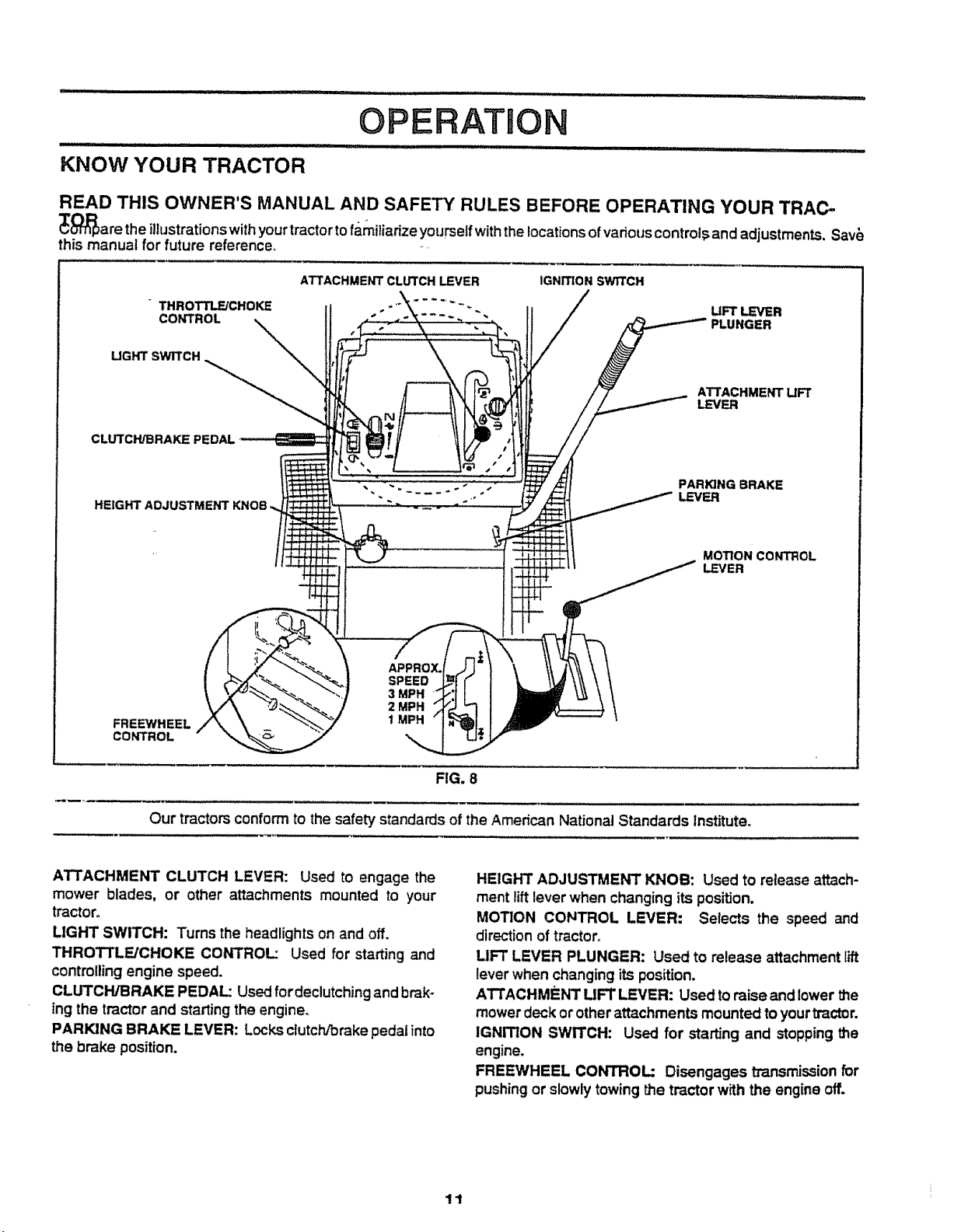
ATTACHMENT CLUTCH LEVER: Used to engage the
mower blades, or other attachments mounted to your
tractor°
LIGHT SWITCH: Turns the headlightson and off.
THROTTLE/CHOKE CONTROL: Used for starting and
controllingengine speed.
CLUTCH/BRAKE PEDAL: Used fordeclutching and brak-
ing the tractor and starting the engine.
PARKING BRAKE LEVER: Locksclutch/brakepedal into
the brake position.
FIG. 8
HEIGHT ADJUSTMENT KNOB: Used to release attach-
ment lift lever when changing its position.
MOTION CONTROL LEVER: Selects the speed and
direction of tractor,
LIFT LEVER PLUNGER: Used to release attachment lift
lever when changing its position.
ATTACHMENT UFT LEVER: Used toraise and lower the
mowerdeck or otherattachments mounted toyourtractor,
IGNITION SWITCH: Used for starting and stopping the
engine.
FREEWHEEL CONTROL: Disengages transmissionfor
pushing or slowly towing the tractor with the engine off.
11
OPERATION
The operation of any tractor can result in foreign objects thrown into the eyes, which
can result in severe eye damage. Always wear safety glasses or eye shields while
operating your tractor or performing any adjustments orrepairs. We recommend a wide
vision safety mask for over _e spectacles or standard safety glasses.
HOW TO USE YOUR TRACTOR
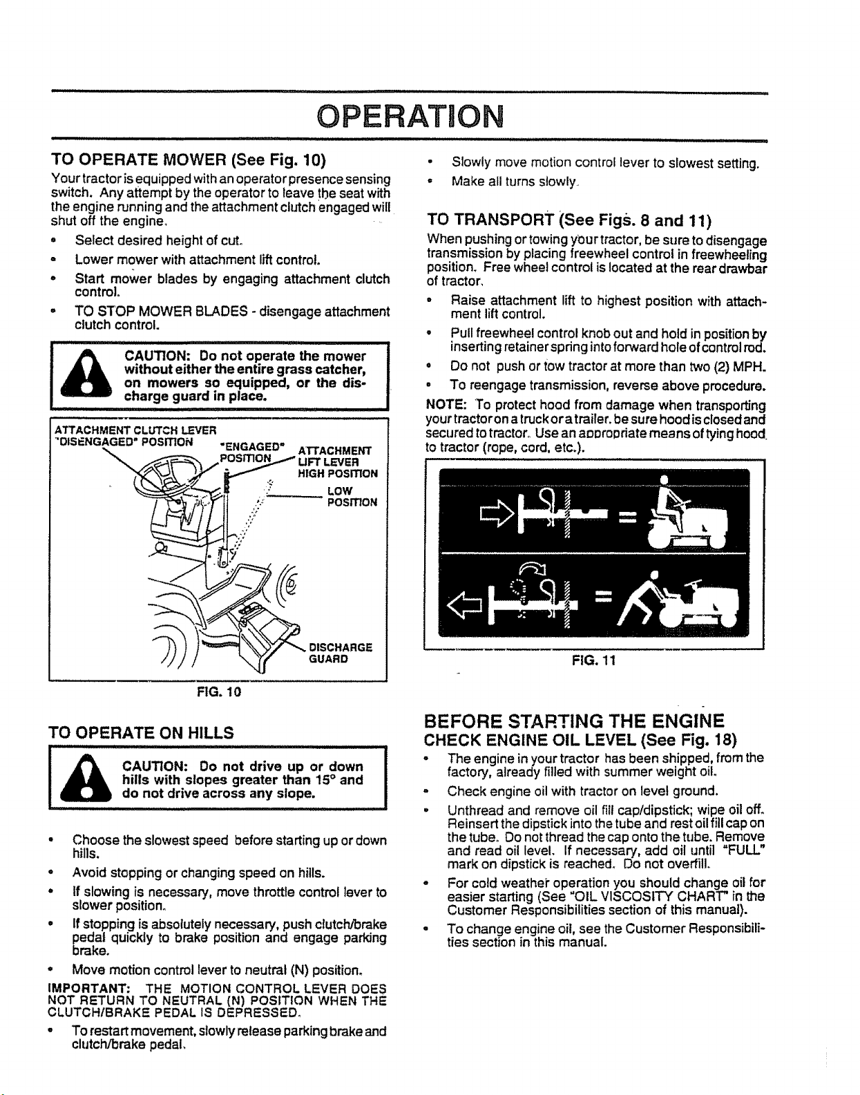
TO SET PARKING BRAKE (See Fig. 9)
Your tractor isequipped withan operatorpresence sensing
switch. When engine is running, any attempt by the
operator to leave the seat withoutfirst setting the parking
brake witl shut off the engine.
• Depress clutch/brake pedal into full "BRAKE" position
and hold.
• Place parking brake lever in "ENGAGED" positionand
release pressurefrom clutch!brakepedal. Pedalshould
remain in"BRAKE"position° Make sure parking brake
will hold vehicle secure.
ATTACHMENTCLUTCH_VER
"ENGAGED"
IGNITION KEY%,,_
THROT3"LFJ "ENGAGED"
CHOKE POSITION
CONTROL "_,
LEVER MOTION
"BRAKE" LEVER
POSITION
CLUTCH/BRAKE HEIGHT PARKING BRAKE
PEDAL "DRIVE" ADJUSTMENT "DISENGAGED"
POSITION KNOB POSITION
RG. 9
STOPPING (See Fig. 9)
MOWER BLADES -
• Move attachment clutch lever to "DISENGAGED" po-
sition.
GROUND DRIVE -
• Depress clutch/brake pedal intofull "BRAKE" position.
• Move motion control lever to neutral (N) position.
IMPORTANT: 'THE MOTION CONTROL LEVER DOES
NOT RETURN TO NEUTRAL (N) POStTION WHEN THE
CLUTCH/BRAKE PEDAL IS DEPRESSED.
ENGINE -
- Move throttle control toslow (-1_) position.
NOTE: Failure to move throttle control to slow (-=i)
position and allowing engine to idle before stopping may
cause engine to "backfire".
"DISENGAGED =
POSITION
PARKING BRAKE
CONTROL
• Turn ignitionkey to "OFF" position and remove key.
Always remove key when leaving tractor to prevent
unauthorized use.
• Never use choketo stop engine,
NOTE: Under certainconditionswhen tractor is standing
idlewith the engine running, hot engine exhaust gases may
cause "browning" of grass° To eliminate this possibility,
always stop engine when stopping tractor on grass areas.
CAUTION: Always stop tractor com-
pletely, asdescribed above, before leav-
ing the operator's position; to empty
grass catcher, etc.
TO USE THROTTLE CONTROL (See Fig. 9)
Always operate engine at full throttle.
• Operating engine at less than full throttle reduces the
battery charging rate_
• Full throttle offers the best bagging and mower perfor-
mance,
TO MOVE FORWARD AND BACKWARD
(See Fig. 9)
The direction and speed of movement is controlledby the
motion control lever_
• Start tractor with motion control lever in neutral (N)
pos3tion.
• Release parkingbrake and clutch/brake pedal.
• Slowly mow motion control lever to desired position;"
TO ADJUST MOWER CUTTING HEIGHT
(See Fig. 9)
The cuttingheightiscontrolledby turning the heightadjust-
ment knob in desired direction.
• Turn knob clockwise ((-_) to raise cutting heighL
• Turn knob counterclockwise (_) to lower cutting
height.
The cutting height range is approximately 1-1/2°to 4°. The
heights are mi_asured from the ground to the blade tipw_
the engine not running. These heights are approximate
and may vary depending upon soil conditions, height of
grass and types of grass being mowed.
• The average lawn should be cutto approximately 2-1/2
inches during the cool season and to over 3 inches
dudng hot months. For healthier and better looking
lawns, mow oftenand after moderate growth.
- For best cutting performance, grass over 6 inches in
height should be mowed twice. Make the first cut
relatively high; the second to desired height.
OPERATION
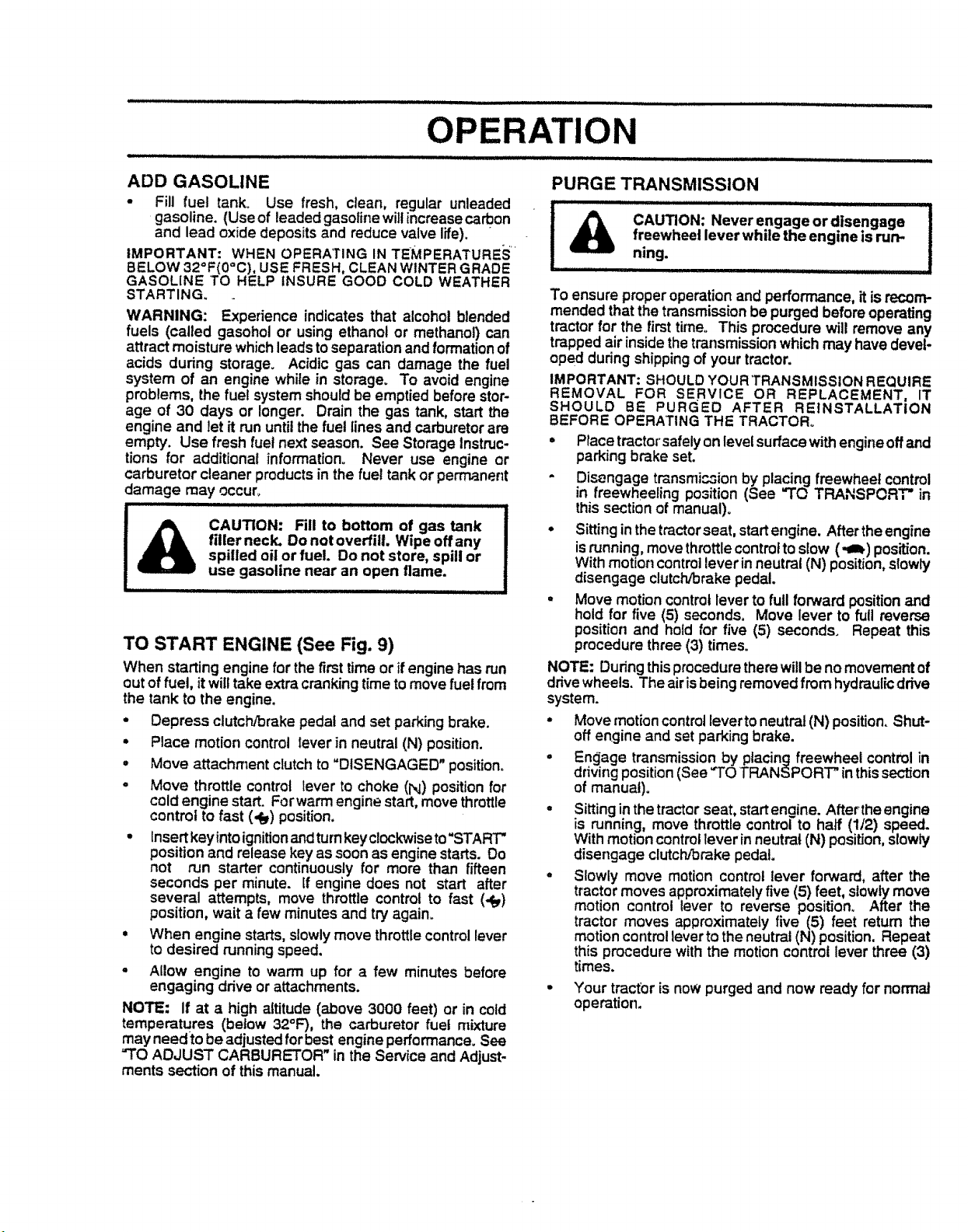
TO OPERATE MOWER (See Fig. 10)
Yourtractor is equippedwithan operatorpresence sensing
switch. Any attempt by the operatorto leave the seat with
the engine runningand the attachment cMch engaged will
shut off the engine.
- Select desired height of cut.
° Lower mower with attachment liftcontrol.
o Start mower blades by engaging attachment clutch
control.
° TO STOP MOWER BLADES - disengage attachment
clutch control.
CAUTION: Do not operate the mower
without either the entire grass catcher,
on mowers so equipped, or the dis-
charge guard in place.
ATTACHMENT CLUTCH LEVER
"DISENGAGED = POSITION
"ENGAGED"
}' LOW
,_: " POSITION
J;
ATTACHMENT
LEVER
HIGH POSiTiON
5"
. Slowly move motion control lever to slowest setting.
o Make all turns slowly
TO TRANSPORT (See Figs. 8 and 11)
When pushingor towingy_ur tractor,be sure to disengage
transmission by placing freewheel control infreewheeling
position. Free wheetcontrol islocated at the rear drawbar
of tractor,
• Raise attachment lift to highest position with attach-
ment lift control.
• Pull freewheel controlknob out and hold in positionby
inserting retainer springintoforward hole ofcontrol rod.
• Do not push or tow tractor at more than two (2) MPH.
• To reengage transmission, reverse above procedure.
NOTE: To protect hood from damage when transporting
your tractor on atruckor atrailer_be sure hood isclosed and
secured totractor° Use anappropriate means oftying hood,
to tractor (rope, cord, etc.).
__, DISCHARGE
GUARD
FIG. 10
TO OPERATE ON HILLS
CAUTION: Do not drive up or down
hills with slopes greater than 15° and
do not drive across any slope.
- Choose the slowest speed before starting up or down
hills.
° Avoid stopping or changing speed on hills.
° If slowing is necessary, move throttle controllever to
slower position.
= If stopping is absolutely necessary, push cMch/brake
pedal quickly to brake position and engage parking
brake.
- Move motion control lever to neutral (N) position.
IMPORTANT: THE MOTION CONTROL LEVER DOES
NOT RETURN TO NEUTRAL (N) POSITION WHEN THE
CLUTCHIBRAKE PEDAL IS DEPRESSED.
. To restartmovement, slowly release parkingbrake and
clutch/brake pedal,
FIG. 11
BEFORE STARTING THE ENGINE
CHECK ENGINE OIL LEVEL (See Fig, 18)
- The engine in your tractor has been shipped, from the
factory, already filled with summer weight oil.
- Check engine oil with tractor on level ground.
• Unthread and remove oil fill cap/dipstick; wipe oil off.
Reinsert the dipstick into the tube andrest oil fill cap on
the tube. Do not thread the cap onto the tube. Remove
and read oil level, if necessary, add oil until "FULL"
mark on dipstick is reached_ Do not overfill.
° For cold weathei" operation you should change oil for
easier starting (See "OIL VISCOSITY CHART" in the
Customer Responsibilities section of this manual).
= To change engine oil, see the Customer Responsibili-
ties section in this manual.
OPERATION
................................ i i iii illii __
ADD GASOLINE
• Fill fuel tank. Use fresh, clean, regular unleaded
gasoline. (Use of leaded gasolinewiltincrease carbon
and lead oxide deposits and reduce valve life). "
IMPORTANT: WHEN OPERATING IN TEMPERATURES'
BELOW 32°F(0"C), USE FRESH, CLEAN WINTER GRADE
GASOLINE TO HELP INSURE GOOD COLD WEATHER
STARTING.
WARNING: Experience indicates that alcohol blended
fuels (called gasohol or usingethanol or methanol) can
attract moisture whichleads toseparation andformation of
acids during storage. Acidic gas can damage the fuel
system of an engine while in storage. To avoid engine
problems, the fuel system shouldbe emptied before stor-
age of 30 days or longer. Drain the gas tank, start the
engine and let it rununtil the fuel lines and carburetor are
empty. Use fresh fuel nextseason. See Storage Instruc-
tions for additional information° Never use engine or
carburetor cleaner products in the fue! tank or permanent
damage may occur°
usespilledfiUerneck.CAUTION:.............................................................................gasolineoil orDo not overfill.Fillfuel.nearto Doanbottomnotopenstore,Wipeofflame,gasspilloffanytankor !
iHll ill ,,,,,,,,,,,,,,,,,, , .......
TO START ENGINE (See Fig. 9)
When starting engine for the first time or ifengine has run
out offuel, itwilltake extra cranking time to move fuel from
the tank to the engine.
• Depress clutch!brake pedal and set parking brake.
• Place motion control lever in neutral (N) position.
° Move attachment clutchto "DISENGAGED" position.
° Move throttle control lever to choke (N) position for
cold engine start. Forwarm engine start,move throttle
control to fast (,_) position.
• insert key intoignitionandturnkey clockwiseto"START"
position and release key as soon asengine starts. Do
not run starter continuously for more than fifteen
seconds per minute. If engine does not start after
several attempts, move throttle control to fast (,_)
position, wait a few minutes and try again.
• When engine starts,slowlymove throttle control lever
to desired runningspeed.
- Allow engine to warm up for a few minutes before
engaging drive or attachments.
NOTE: If at a high altitude (above 3000 feet) or in cold
temperatu.res (below 32°F), the carburetor fuel mixture
may need to beadjusted for best engineperformance. See
"TO ADJUST CARBURETOR" in the Service and Adjust-
ments section of thismanual.
PURGE TRANSMISSION
........... |llllll i lu JiuiH i
freewheel lever while the engine is run-
CAUTION: Never engage or disengage
ning.
To ensure proper operationand performance, itis recom-
mended that the transmission be purged before operating
tractor for the first time° This procedure will remove any
trapped air insidethetransmissionwhichmay have devel-
oped duringshippingof your tractor.
IMPORTANT: SHOULDYOUR TRANSMISSION REQUIRE
REMOVAL FOR SERVICE OR REPLACEMENT, IT
SHOULD BE PURGED AFTER REINSTALLATION
BEFORE OPERATING THE TRACTOR°
° Place tractorsafelyonlevel surfacewith engineoffand
parking brake set.
" Disengage transmi_ion by placing freewheel control
in freewheeling po.=ition(See "TO TRANSPORT" in
this section of manual).
° Sittingin the tractorseat, startengine. Afterthe engine
isrunning, move throttlecontrolto slow (,qI_) position.
With motion controllever inneutral (N) position,slowly
disengage clutch/brake pedal.
° Move motion control lever to full forward positionand
hold for five (5) seconds. Move lever to full reverse
position and hold for five (5) seconds. Repeat this
procedure three (3) times.
NOTE: During this procedure therewillbeno movementof
drive wheels. The airisbeing removed from hydraulicdrive
system.
° Move motion controlleverto neutral (N) position. Shut-
off engine and set parking brake.
• Engage transmissionby placing freewheel control in
drivingposition(See "TO TRANSPORT" inthissection
of manual).
• Sittingin thetractor seat, startenoine. Afterthe engine
is running, move throttle controi'to half (112) speed.
With motion controllever inneutral (N) position,slowly
disengage clutch/brake pedal
= Slowly move motion control lever forward, after the
tractor moves approximatelyfive (5) feet, slowlymove
motion control lever to reverse position. After the
tractor moves approximately five (5) feet return the
motion controllever to the neutral (N) position. Repeat
this procedure withthe motion control lever three (3)
times.
• Your tractor is now purged and now ready for normal
operation.
MOWING TIPS
• Tire chains cannot be used when the mower housing
is attached to tractor.
o Mower should be properly leveled for best mowjn_
perforrnance_ See"TO LEVEL MOWER HOUSING in
the Service and Adjustments section of this manual.
o The left hand side of mower should be used for trim-
ming.
° Drive so that clippingsare discharged onto the area
that has been cut. Have the cutarea to the right of the
machine. This will result ina more even distribution of
clippings and more uniform cutting°
° When mowing large areas, start by turning to the right
so that clippings will discharge away from shn_bs,
fences, driveways, etc, After one or two rounds, mow
in the opposite direction making left hand turnsuntil
finished (See Fig. 12 ).
° if gra_ is extremely tat!, it should be mowed twice to
reduce load and possible fire hazard from dried clip-
pings. Make first cutrelatively high; the second to the
desired height.
= Do not mow grass when it is wet. Wet grass willplug
mower and leave undesirable clumps. Allow grass to
dry before mowing.
° Always operate engine at full throttle when mowing to
assure better mowing performance and proper dis-
charge of material. Regulate ground speed by select-
ing a low enough gear to give the mower cutting
performance as well as the quality of cutdesired.
o When operating attachments, select a ground speed
that will suit the terrain and give best performance of
the attachment being used.
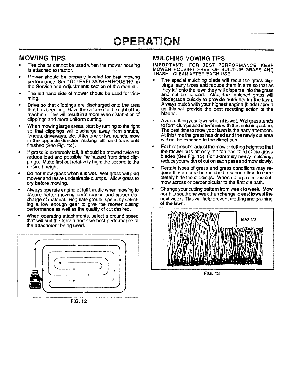
MULCHING MOWING TIPS
IMPORTANT: FOR BEST PERFORMANCE, KEEP
MOWER HOUSING FREE OF BUILT-UP GRASS AND
TRASH., CLEAN AFTER EACH LJSEo
° The special mulching blade will recut the grass clip-
pings many times and reduce them in size so that as
they fall onto the lawn they willdisperse intothe grass
nd not be noticed. Also, the mulched grass will
iodegrade quickly to provide nutrients for the lawn.
Always mulch withyour highest engine (blade) speed
as this will provide the best recutting action of the
blades.
° Avoid cuttingyour lawnwhen itis wet. Wet grass tends
to form ctumpsand interferes withthe mulchingaction.
The best timeto mow your lawn is the early afternoon.
At thistimethegrass has dried and the newlycutarea
will not be exposed to the direct sun.
° Forbest results, adjustthe mowercuttingheightsothat
the..mower cuts.Qffonly the top one=third of the grass
blades (See F=g.13). For _xtremely heav'_ mulching,
reduce yourwidth of cut on each pass and mow slowly.
° Certain typesof grass and grass conditions may re-
quire that an area be mulched a second time to com-
pletely hide the clippings. When doing a second cut,
mow across or perpendicular to the first cut path.
° Change your cuttingpattern from week to week. Mow
north tosouth oneweek then change to east to westthe
nextweek. This will help prevent matting and graining
of the lawn.
MAX I/3
FIG, 12
FIG. 13
i,, ,ill, i llll ...........................
CUSTOMER RESPONSIBILITIES
/ ,,ill ii i '"' ' ..................................... iiiiiiill illllll illll i
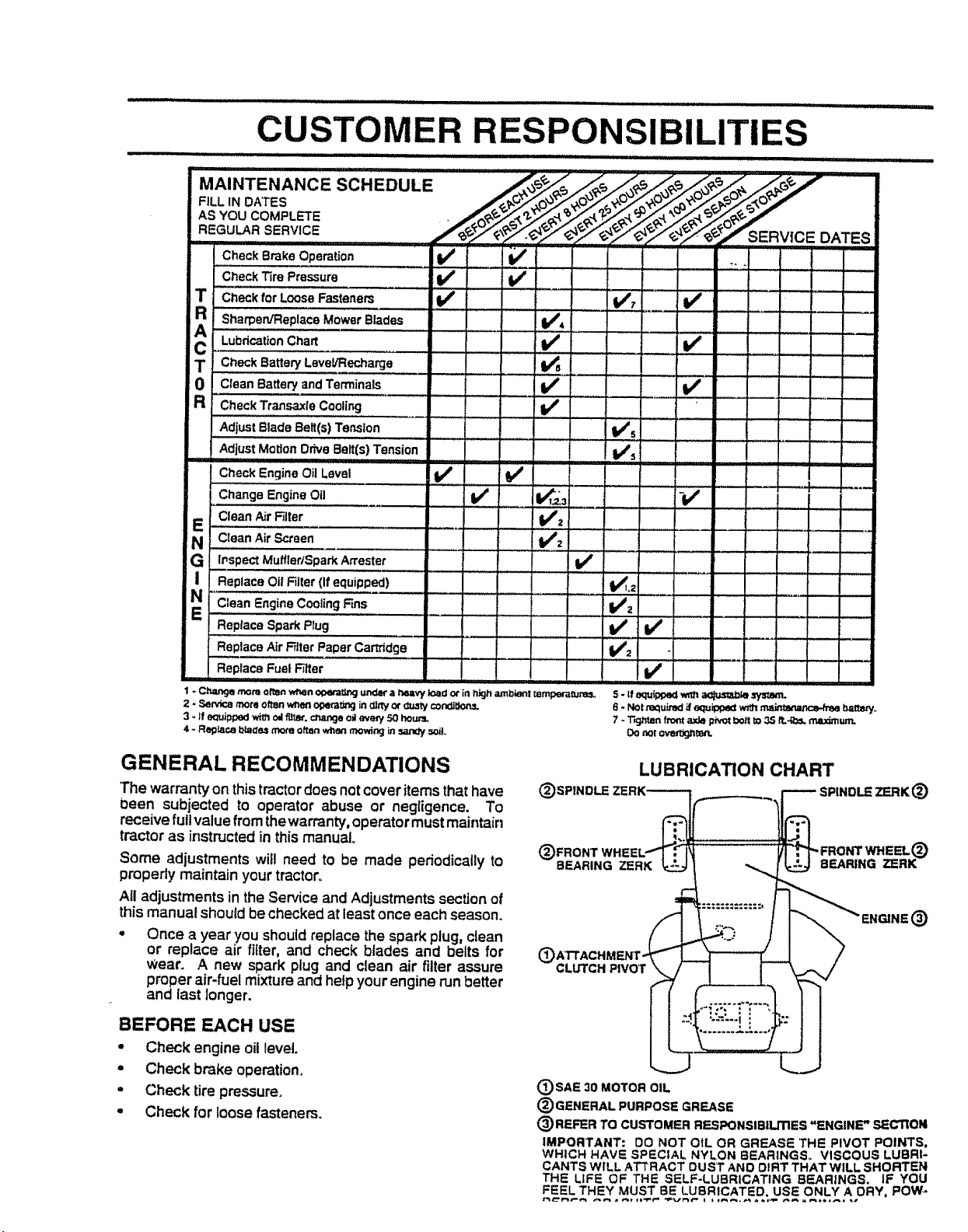
MAINTENANCE
FILL IN DATES
AS YOU COMPLETE
REGULAR SERVICE
Check Brake Operation
Check Tire Pressure
Check for Loose Fasteners
R Sharpen/Replace Mower Blades
! Lubricationchart
T CheckBatten/Level/Recharge ....... I/_ .....
0 Clean Battery and Terminals
R CheckTtansaxieCooling If
AdjustBladeBelt(s) Tension
AdjustMotionDrive Belt(s)Tension
CheckEngineOil Level ......... I,/ b/
Change Engine Oil If 1_,_3
E Clean AirR!ter ............... 1/2
N c_eanAir_oen............ -...........i. _ _V'2
G i LnspectMuffler/SparkArrestet......... tf ..................
I Replace OilFiller(If equipped) t_L2
Clean EngineCoolingFins li/z
Replace Spark Plug .... tk/
ReplaceAirFiller PaperCartridge i,/2
ReplaceFuel Filter
1 - Ch=u-,gemonaolton _n of>e_Cr_gunder a P,eaW loado_ in high ambient tampem_Jna_,
2 * SeP..icomorn oftenwhen of_t_g in _rty cA"_._/con_t_._
3 - tf e_Jip_oedwireoil furor,€_,_u,,geoil eve_ 50 houPJ.
4 - Reglaca bla_o,g_ often when mowir,_ in_ soil,.
IIIIIIIII I1'1 I
,,,,,,,,, ,, ,,,,,,
i/ v'
v' ...............' :v',......v' ....................
v' i/
W_s
8 - Notmquved_equ_ _ main_ b=t_rf.
7 oT_g_tanfrom_de pivotbo_tto 35 ft.*g0s,maximum.
Dorot ove_gnm_r'_.
v'
; " : : .........r _..• :
-v'
v'
i , 7 :
v'
,ll i,i
i.....
GENERAL RECOMMENDATIONS
The warranty on thistractordoes notcover itemsthat have
0een subjected to operator abuse or negligence. To
receive full value from thewarranty,operatormust maintain
tractor as instructedin thismanu_
Some adjustments will need to be made periodically to
properly maintain your tr_ctoro
All adjustments in the Service and Adjustments sectionof
this manual should bechecked atleastonce each season.
o Once a year you shouldreplace the spark plug, clean
or replace air fitter, and check btades and belts for
Wear. A new spark ptug and clean air filter assure
proper air-fuel mixture and heipyour engine runbetter
and last Ionger.
BEFORE EACH USE
o Check engine oitlevel.
• Check brake operation.
° Check tire pressure,
o Check for loose fasteners.
LUBRICATION CHART
(_SPINDLE _)
(_FRONT WH
BEARING ZERK
C
CLUTCH PIVOT
(_SAE 30 MOTOR OIL
® GENERAL PURPOSE GREASE
® REFER TO CUSTOMER RESPONSlBiUTIES "ENGINE" SECTION
IMPORTANT: 00 NOT OIL OR GREASE THE PIVOT POINTS,
WHICH HAVE SPECIAL NYLON BEARtNGS_. VISCOUS LUBRI-
CANTS WILL ATTRACT OUST AND OtRT THAT WILL SHORTEN
THE LIFE OF THE SELF-LUBRICATING BEARINGS. IF YOU
FEEL THEY MUST BE LUBRICATED. USE ONLY A ORY, POW _
®
CUSTOMER P SIBILITI
TRACTOR
Always observe safety ruleswhen performing any mainte-
nance.
BRAKE OPERATION
If tractor requires more than six (6) feet stopping distance
at high speed_inhighest gear, then brake must be.adjusted.
(See "TO ADJUST BRAKE" in the Service and Adjust-
ments section of this manual).
TIRES
• Maintain proper air pressure in all tires (See "PROD-
UCT SPECIFICATIONS" on page 3 of this manual).
= Keep tires free of gasoline, oil, or insect controlchemi-
cals which can harm rubber.
o Avoid stumps, stones, deep ruts, sharp objects and
other hazards that may cause tire damage.
BLADE CARE
For best results mower blades must be kept sharp_ Re-
place bent or damaged blades.
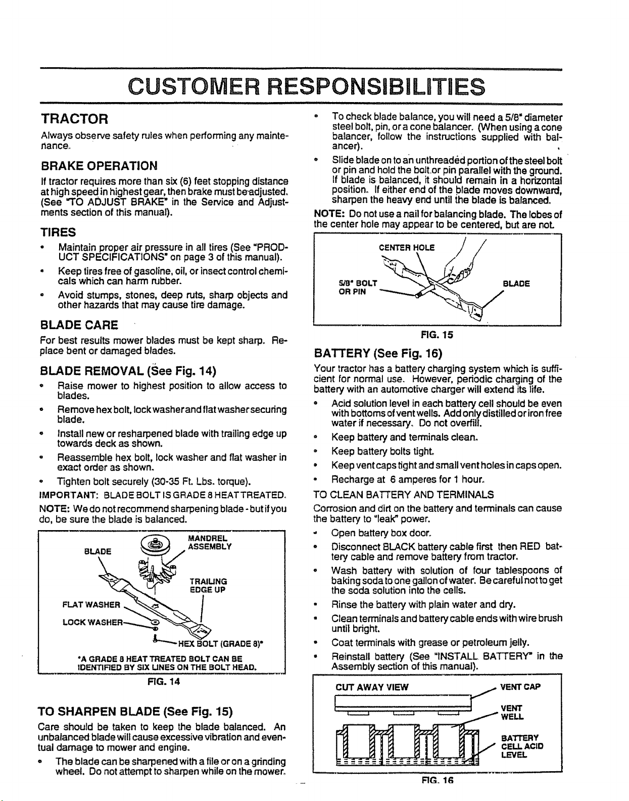
BLADE REMOVAL (See Fig. 14)
° Raise mower to highest position to allow access to
blades.
° Remove hex bolt, Iockwasherand ftat washersecuring
blade.
° install new or resharpened blade with trailing edge up
towards deck as shown.
o Reassemble hex bolt, lockwasher and flat washer in
exact order as shown.
° Tighten bolt securely (30-35 Ft. Lbs. torque).
IMPORTANT: BLADE BOLT ISGRADE 8 HEATTREATED.
NOTE: We do not recommend sharpening blade- but ifyou
do, be sure the blade is balanced.
"A GRADE 8 HEAT TREATED BOLT CAN BE
IDENTIRED BY SiX LINES ON THE BOLT HEAD.
RG. 14
TO SHARPEN BLADE (See Fig. 15)
Care should be taken to keep the blade balanced. An
unbalanced bladewill causeexcessivevibrationandeven-
tual damage to mower and engine.
° The blade can be sharpenedwitha file oron a grinding
wheel. Do not attempttosharpenwhile on themower.
o To check blade balance, you wilt need a 5/8" diameter
steel bolt, pin,ora conebalancer. (When using acone
balancer, follow the instructions supplied with bal-
anger).
° Slide blade ontoan unthreaded portionof the steel bolt
or pin and hold the boltor pinparallel with the ground.
If blade is balanced, it should remain in a horizontal
position. If either end of the blade moves downward,
sharpen the heavy end until {heblade is balanced.
NOTE: Do notusea nailfor balancing blade. The lobes of
the center hole may appear to be centered, but are noL
CENTER HOLE /
OR PIN
5/8" BOLT _BLADE
RG. 15
BATTERY (See Fig. 16)
Your tractor has a batterycharging system which is slfffi-
cient for normal use. However, periodic charging of the
battery with an automotive charger will extend its life.
° Acid solutionlevel in each battery cell should be even
with bottoms ofventwells. Addonlydistilled oriron free
water if necessary° Do not overfill.
° Keep battery and terminals clean°
- Keep battery bolts tight.
= Keep vent caps tight andsmall vent holes in capsopen.
° Recharge at 6 amperes for 1 hour.
TO CLEAN BATTERY AND TERMINALS
Corrosion and dirt on the battery and terminals can cause
the battery to "leak" power.
- Open battery box door.
° Disconnect BLACK battery cable first then RED bat-
tery cable and remove battery from tractor.
° Wash battery with solution of four tablespoons of
baking soda toone gallon ofwater. Be carefulnotto get
the soda solution into the cells.
° Rinse the battery with plain water and dry.
- Clean terminals and battery cable ends with wire brush
until bright.
• Coat terminals with grease or petroleum jelly.
• Reinstall battery (See "INSTALL BATTERY" in the
Assembly section of this manual).
CUTAWAY VIEW VENTCAP
I S,o.,
_ _ WELL
BATTERY
CELL ACID
LEVEL
FIG. 1G
• i,iiiiilll i iiiiiii ii i iii lull _ _ I,,,1"11 _ IllU II ........................................
CUSTOMER RESPONSIBILITIES
............. • .................................. 111 11 , I IIIIII II I ...- II,lllUH II , II1,1,1,1 I
TRANSAXLE COOLING TO CHANGE ENGINE OIL (See Fig. 17)
The fan and cooling fins of transmission should be kept
clean to assure proper cooling,
Do not attempt to clean fan or transmission while engine is
running or while the transmission is hot.
° Inspect cooling fan to be sure fan blades are intact and
clean.
° Inspect cocklingfins for dirt, grassclippingsand other
materials. To prevent damage to seals, do notuse
compressed air or high pressure sprayer to clean
cooling fins.
TRANSAXLE PUMP FLUID
The transaxle was sealed at the factory and fluid mainte-
nance is not required fort.he life ofthe transaxle. Should the
transaxle ever leak or require servicing, contactyour near-
est authorized service center/departmenL
V-BELTS
Check V--beltsfor deterioration andwear after 100 hours of
operation and replace if necessary. The belts are not
adjustable. Replace belts ifthey begin to slipfrom wear.
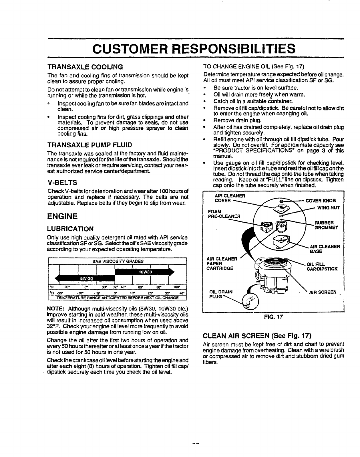
ENGINE
LUBRICATION
Only use high quality detergent oil rated withAPI service
classification SF or SGoSelect the oil'sSAE viscosity grade
according to your expected operating temperature.
SAE VISCOSITY GRADES
Determine temperature range expected before oilchange.
All oil must meet API service classification SF or SG.
° Be sure tractor is on level surface.
• Oil will drain more freely when warm.
o Catch oil in a suitable _bhtainero
° Remove oil fill cap/dipstick, Re careful not to allow dirt
to enter the engine when changing oil.
° Remove drain plug.
° After oil has drained completely, replace oil drain plug
and tighten securely.
° Refill engine with oil through oil fill dipstick tube. Pour
slowly. Do not overfill. For approximate capacity see
"PROOUCT SPECIFICATIONS on page 3 of this
manual°
° Use gauge on oil fill capldipst_ckfor checking level.
insertdipstick into the tube and restthe oil fill cap onthe
tube. Do not thread the cap ontothe tube when taking
reading. Keep oil at "FULL"line on dipsticK. Tighten
cap onto the tube securely when finished.
AIR CLEANER
COVER
FOAM
PRE-CLEANER
NR CLEANER
PAPER _LL
CARTRIDGE CAP_IPS'RCK
COVERKNOB
WING NUT
RUBBER
CLEANER
BASE
°F -20" 0" 3_ 3,2" t0'* 8_ 80" 10_
°CC .30" .1_' .t0 • 0" t_ _ 30" 40"
TEM_-IRATLj'RE RANGE ANTICIPATED BI_FOFtI_ NEXT OIL CHANGE
NOTE: Although multi-viscosity oils (5W30, 10W30 etc.)
improve starting in cold weather, these multi-viscosity oils
will result in increased oil consumption when used above
32°F, Check your engine oil level more frequently to avoid
possible engine damage from running low on oil
Change the oil after the first two hours of operation and
every 50 hours thereafter or at leastoncea year ifthe tractor
is not used for 50 hours in one year.
Checkthe crankcase oil level before starting the engineand
after each eight (8) hours of operation. Tighten oil fill cap/
dipstick securely each time you check the oil level.
OIL ORAIN AIR SCREEN _
FIG. 17
CLEAN AIR SCREEN (See Fig. 17)
Air screen must be kept free of dirt and chaff to prevent
engine damage from overheating. Clean with a wire brush
or compressed air to remove dirt and stubborn dried gum
fibers°
 Loading...