

Craftsman 917257660 Owner’s Manual

SWA/, S
[RRFTSMaN°
NUMBER 917.257660 OWNER'SMANUAL
TM
° Assembly
° Operation
° Customer Responsibilities
° Service and Adjustments
° Repair Parts
CAUTION: Read and follow all safety rules and instructions before operating this equipment.
i
............................. i i _ ,i II ' I
IIIIIIIIIIIIIIIIIIIIIIIIIIIIIIIIIIIIIIIIIIIII I 'l

Safe Operation Practices for Ride-On Mowers
SAFETY RULES
IMPORTANT: THIS CUTTING MACHINE IS CAPABLE OF AMPUTATING HANDS AND FEETAND THROWING OBJECTS
FAILU RETO OBSERVE TH E FOLLOWING SAFETY INSTRUCTIONS COULD RESULT INSERIOUS INJURY OR DEATH.
I. GENERAL OPERATION
• Read, understand, and follow all instructions in the manual
and on the machine before starting..
• Only allow responsible adults, who are familiar with the
instructions, to operate the machine.
• Clear the area of objects such as rocks, toys, wire, etc,
which could be picked up and thrown by the blade.
• Besuretheareaisclearofotherpeoplebeforemowing Stop
machine if anyone enters the area.
• Never carry passengers
• Do not mow in reverse unless absolutely necessary. Always
look down and behind before and while backing.
• Be aware of the mower discharge direction and do not point
it at anyone. Do not operate the mower without either the
entire grass catcher or the guard in place
• Slow down before turning.r
• Never leave a running machine unattended Always turn off
blades, set parking brake, stop engine, and remove keys
before dismounting
o Turn off blades when not mowing+
• Stop engine before removing grass catcher or unc!ogging
chute.
° Mow only in daylight or good artificial ]ighto
° Do not operate the machine while under the influence of
alcohol or drugs
,, Watch for traffic when operating near orcrossing roadways+
. Use extra care when loading or unloading the machine into
a trailer or truck.
II. SI.OPE OPERATION
Slopes are a major factor related to loss-of-control and tipover
accidents, which can result [n severe injury or death. All slopes
require extra caution. If you cannot backup the slope or [fyou feel
uneasy on it, do not mow it..
DO:
• Mow up and down slopes, not across.
• Remove obstacles such as rocks, tree limbs, etc+
• Watch for hotes, ruts, or bumps.. Uneven terrain could
overturn the machine Tall grass can hide obstacles.
• Use slow speed, Choose a lowgear so that you will not have
to stop or shift white on the slope.
° Follow the manufacturer's recommendations for wheel
weights or counterweights to improve stability
• Use extra care with grass catchers or other attachments.
These can change the stability of the machine.
• Keep all movement on the slopes slowand gradual Do not
make sudden changes in speed or direction
• Avoid starting or stopping on a slope.. If tires lose traction,
disengage the blades and proceed slowly straight down the
slope.
DO NOT:
• Donot turn on slopes unless necessary, and then, turn slowly
and gradually downhill, if possible.
• Donotmow near drop-offs, ditches, or embankments. The
mower could suddenly turn over if a wheel is over the edge
of a cliff or ditch, or if an edge caves in.
• Do not mow on wet grass. Reduced traction could cause
sliding+
• Donot
groundtry, to stabilize the machine by putting your foot on the
• Do not use grass catcher on steep slopes,
III. CHILDREN
Tragic accidents can occur if the operator is not alert to the
presence of children.. Children are often attracted to the machine
and the mowing activity.. Neverassume that children will remain
where you last saw them
• Keep children out of the mowing area and under the watchful
care of another responsible adult
• Be alert and turn machine off if children enter the area
• Before and when backing, look behind and down for small
children.
* Never carry children. They may fall off and be seriously
injured or interfere with safe machine operation
• Never allow children to operate the machine.
• Use extra care when approaching Mind corners, shrubs,
trees, or other obiects that may obscure vision.
IV. SERVICE
° Use extra care inhandling gasoline and other fuels They are
flammable and vapors are explosive.
Use only an approved container.
Never remove gas cap or add fuel with the engine
running. Allow engine to cool before refueling Do not
smoke.
Never i'efuel the machine indoors.
Never store the machine or fue! container inside where
there is an open flame, such as a water heater+
° Never run a machine inside a closed area
,, Keep nuts and bolts, especially blade attachment bolts, tight
and keep equipment in good condition.
• Never tamper with safety devices Check their proper
operation regularly.
• Keepmachinefreeofgrass leaves orotherdebrisbuild-up
Clean oil or fuel spillage Allow machine to coo before
stodng
* Stop and inspect the equipment if you strike an object
Repair, if necessary, before restarting.
• Never make adjustments or repairs with the engine running
• Grass catcher components are subject towear, damage, and
deterioration, which could expose moving parts or allow
objects to be thrown. Frequently check components and
replace with manufacturer's recommended parts, when nec-
essary.
• Mower blades are sharp and can cut. Wrap the blade(s) or
wear gloves, and use extra caution when servicing them
,, Check brake operation frequently Adjust and service as
required.
iiii i llUllUlllU i ii iiiiilUllllmmll
Look for this symbol to point out impor-
tant safety precautions. It rn-eans
CAUTION!!! BECOME ALERT!!! YOUR
SAFETY IS INVOLVED.
CAUTION: Always disconnect spark
plug wire and place wire where it cannot
contact spark plug in order to prevent
accidental starting when setting up,
transporting, adjusting or making
repairs.
i i i iiiIIIHIII I I II III Illllllllll
2

CONGRATULATIONS on your purchase of a Sears
tractor. It has been designed, engineered and manufac-
tured to give you the best possible dependability and
performance,.
Should you experience any problem you cannot easily
remedy, please contact your nearest Sears Service
Center/Department We have competent, weIFtrained
technicians and the proper tools to service or repair this
unit.
Please read and retain this manual. The instructions will
enable you to assemble and maintain your unit properly.
Atways observe the SAFETY RULES.
MODEL
NUMBER 917,257660
SERIAL
NUMBER
DATE OF PURCHASE
THE MODELAND SERIAL NUMBERSW1LL BE FOUND
ON A PLATE UNDER THE SEAT.
YOU SHOULD RECORD BOTH SERIAL NUMBER AND
DATE OF PURCHASE AND KEEP IN A SAFE PLACE
FOR FUTURE REFERENCE
MAINTENANCE AGREEMENT
A Sears maintenance agreement isavailable on this prod-
ucto Contact your nearest Sears store for details.
CUSTOMER RESPONSIBILITIES
- Read and observe the safety rules.
, Follow a regular schedule in maintaining, caring for and
using your unit.
• Follow the instructions under "Customer Responsibili-
ties" and "Storage" sections of this owner's manual.
PRODUCT SPECIFICATIONS
HORSEPOWER: 15.5
GASOLINE CAPACITY 3.5 GALLONS
AND TYPE: UNLEADED REGULAR
OIL TYPE (AP_-SG): SAE 30 (above32°F)
SAE 5W-30 (betow 32°F)
OIL CAPACITY: W/FILTER: 4,5 PINTS
W/O FILTER: 4,0 PINTS
SPARK PLUG: CHAMPION RC12YC
GAP: °030")
VALVE CLEARANCE: INTAKE: 0015" * .0030"
EXHAUST: ,0020" - •0035"
GROUND SPEED (MPH): FORWARD: 5.,62
REVERSE: 2,,4
TIRE PRESSURE: FRONT: 14 PSI
REAR: 12 PSI
CHARGING SYSTEM: 3 AMPS BATTERY
5 AMPS HEADLIGHTS
BLADE BOLT TORQUE: 30-35 FT_LBS,
WARNING: This unit is equipped with an internal combus-
tion engine and should not be used on or near any unim-
proved forest-covered, brush-covered or grass-covered
land unless the engine's exhaust system is equipped with
a spark arrester meeting applicable local or state laws (if
any),. Ifa spark arrester Is used, it should be maintained in
effective working order by the operator,
in the state of California the above is required by law
(Section 4442 of the California Public Resources Cede).
Other states may have similar laws., Federal laws apply on
federal land& A spark arrester for the muffler is available
through your nearest Sears Authorized Service Center
(SeeREPAIR PARTS section of this manual).
LIMITED TWO YEAR WARRANTY ON ELECTRIC START RIDING EQUIPMENT
For two (2) years from the date of purchase, ifthis riding equipment is maintained, lubricated and tuned up according to the
instructions in the owner's manual, Sears will repair or replace, free of charge, any parts found to be defective in material or
workmanship.
This Warranty does notcover:
• Expendable itemswhichbecome worn during normal use, such as blades, spark plugs, air cleaners and belts.
• Tire replacement or repaircaused by puncturesfromoutside objects, such as nails, thorns, stumps, or grass
° Repairs necessary because of operator abuse, negligence,improperstorage or accidentor the failure to maintain the
equipment according to the instruc
SAFETY RULES ............................................................ 2
PRODUCT SPECIFiCATiONS ....................................... 3
CUSTOMER RESPONSIBILITIES ..................... 3, 16-19
WARRANTY ................................................................... 3
TRACTOR ACCESSORIES ........................................... 5
ASSEMBLY .............................................................. 7-10
OPERATION ........................................................... 11-15
INDEX
A
Accessories ........................................... 5
Adjustments:
Brake ............................................... 22
Carburetor ................................ 26
Mower
Front-To-Back ....................... 21
Side-To-Side ................................21
Throttle Control Cable ............. 26
Air Filter, Engine ............................. 19
Air Screen, Engine ............................. 18
Assembly ............................................. 7ol 0
B
Battery:
Charging ..................................... 8
Cleaning ............................................17
Installation ...........................................9
Levels ................................................. 8,17
Preparation ...................................... 8
Starting with Weak Battery .............24
Storage .......................................... 27
Terminals .......................................... 17
Belt:
Motion Drive
Removal/Replacement ........... 23
Mower Belt(s)
Removal/Replacement ........... 22
Blade:
Sharpening ............................ 17
Replacement .....................................17
Brake Adjustment .............................. 22
C
Carburetor Adjustment ......................... 26
Controls, Tractor ........................................11
Customer Responsibilities ................16-19
Engine:
Air Filter ..................................... 19
Air Screen .................................... 18
Cooling Fins ............................... 19
Engine Oil ................................13,18
Fuel Filter ..................................... 19
Spark Plug(s) ............................ 19
Tractor:
Battery .......................................... t 7
Blade .......................................... 17
Lubrication Chart ...................... 16
Maintenance Schedule .............. !6
Tire Care ........................... 8,17,27
Transaxle .................................... t 8
Cutting Height, Mower ............................ 12
Electrical:
Interlocks and Relays .................. 25
Schematic ...................................... 31
Wiring Diagram ................................... 32
Engine:
Air Filter ................................................19
Air Screen ......................................... 18
Cooling Fins ......................................19
Oil Change ........................................18
Oil Level ....................................... 18
Oil Type .................................... 13,18
Preparation ..........................................13
Repair Parts ........................... 50-55
Starting ............................................. 14
Storage ............................................. 27
Filter:
Air Filter ..............................................19
Fuel ........................................ 19
Fuel:
Type ............................................ 14
Storage ........................................... 27
Fuse ......................................................... 25
Hood Removal/Installation .................. 25
Leveling Mower Deck .............................. 21
Lubrication:
Chart ............................................... 16
Engine ...................................... 18
Maintenance Schedule ......................... 16
Mower:
Adjustment, Front4o-Back .............21
Adjustment, Side-to-Side ................21
Blade Replacement ...................... 17
Blade Sharpening ........................... 17
Cutting Height ................................. 12
installation .................................... 20
Operation ........................................ 13
Removal .......................................... 20
Mowing Tips .......................................... 15
Muffler .........................................................19
Spark Arrester .............................. 3,40
MAINTENANCE SCHEDULE ...................................... 16
SERVICE AND ADJUSTMENTS ............................ 20-26
STORAG E .................................................................... 27
TROUBLESHOOTING ............................................ 28-29
REPAIR PARTS - TRACTOR ................................. 32-47
REPAIR PARTS - ENGINE ..................................... 50-55
PARTS ORDERINGISERVlCE ................ BACK COVER
E
Oil:
Cold Weather Conditions ...........12,18
Engine .............................................. 18
Storage ................................................. 27
Operation ..................................................... 11-15
Operating Mower ................................... 13
Options:
Accessories ..................................... 5
Spark Arrester ......................................3,40
O
P
Parking Brake .................................... 11-12
Parts Bag ................................................. 6
Parts, Replacement!Repair ........ 32-47
F
Product Specifications ...............................3
R
Repair Parts ........................................ 32-47
S
Safety Rules ........................................... 2
Seat .................................................................8
H
L
M
Service and Adjustments ..................20-26
Carburetor .......................................... 26
Fuse .................................................. 25
Hood Removal/Installation ........... 25
Motion Drive Belt
Removal/Replacement ........... 23
Mower Belt(s)
Removal/Replacement ...............22
Mower Adjustment
FronFto-Back .............................. 21
Side-to-Side ....................................21
Mower Removal/Installation ......... 20
Tire Care .....................................8,17,27
Slope Guide Sheet .............................. 59
Spark Plug(s) .............................................. 19
Specifications .......................................... 3
Starting the Engine .......................... 14
Steering Wheel .........................................7,24
Stopping the Tractor .... ...........................12
Sto rage ................................................ 27
T
Throttle Control Cable Adjustment ..... 26
Tires ...................................................8,17,27
Trouble Shooting Chart .......................28-29
Transaxle .............................................. 18
W
Warranty ............................................. 3
Wiring Diagram ..................................... 32
4
Wiring Schematic ................................. 31
ACCESSORIES AND ATTACH ENTS
IIHIIII i, ,I,,,,,,I,,,,I,H, ii ,, ii ,,, i,, u,L i ,1,,,,,,,1,
These accessories and attachments were available through most Sears retail outlets and service centers when the tractor was purchased
Most Sears stores can order these items for you when you provide the model number of your tractor
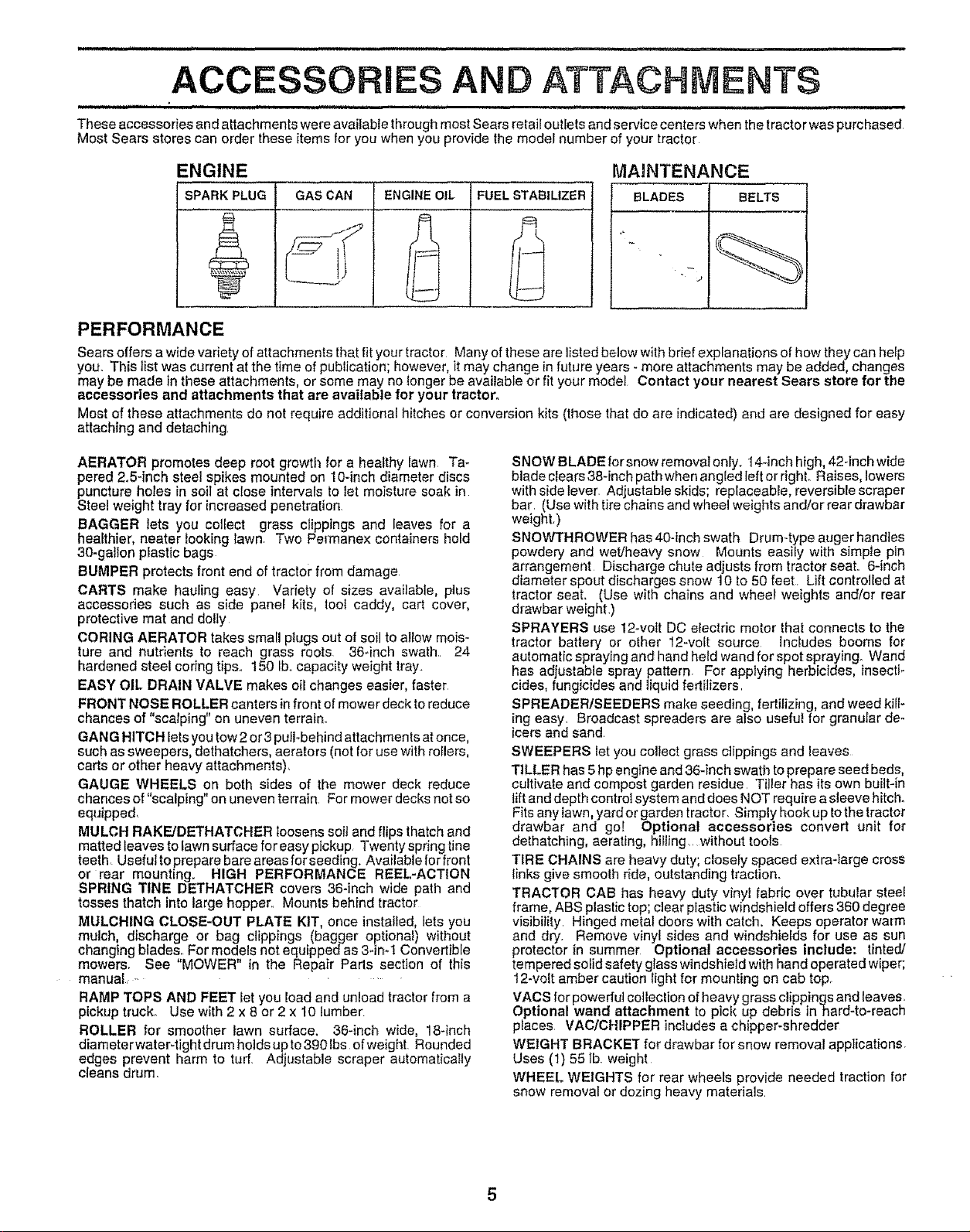
ENGINE
SPARK PLUG GAS CAN ENGINE OIL FUEL STABILIZER
MAINTENANCE
BLADES BELTS
PERFORMANCE
Sears offers a wide variety of attachments that fit your tractor Many of these are listed below with brief explanations of how they can he_p
you. This list was current at the time of publication; however, it may change in future years - more attachments may be added, changes
may be made in these attachments, or some may no tonger be available or fit your model Contact your nearest Sears store for the
accessories and attachments that are available for your tractor°
Most of these attachments do not require additional hitches or conversion kits (those that do are indicated) and are designed for easy
attaching and detaching,
AERATOR promotes deep root growth for a healthy lawn Ta-
pered 2.5-inch steel spikes mounted on 10-inch diameter discs
puncture holes in soil at close intervals to let moisture soak in
Steel weight tray for increased penetration,
BAGGER lets you collect grass clippings and leaves for a
heafthier, heater looking lawn Two Permanex containers hold
30-gallon plastic bags
BUMPER protects front end of tractor from damage
CARTS make hauling easy Variety of sizes available, pius
accessories such as side pane[ kits, tool caddy, cart cover,
protective mat and dolly
CORING AERATOR takes small plugs out of soil to atlow mois-
ture and nutrients to reach grass roots, 36*inch swath,, 24
hardened steel coring tips. 150 lb.,capacity weight tray..
EASY OIL DRAIN VALVE makes oil changes easier, faster
FRONT NOSE ROLLER canters infront of mower deck to reduce
chances of "scalping" on uneven terrain,
GANG HITCH lets you tow 2 or3 pufl-behind attachments atonce,
such as sweepers, dethatchers, aerators (not for use with toilers,
carts or other heavy attachments),
GAUGE WHEELS on both sides of the mower deck reduce
chances of "scalping" on uneven terrain, For mower decks not so
equipped,
MULCH RAKE/DETHATCHER Ioosens soil and flips thatch and
matted leaves to fawn surface for easy pickup Twenty spring tins
teeth, Useful to prepare bare areas forseeding. Available for front
or rear mounting. HIGH PERFORMANCE REEL-ACTION
SPRING TINE DETHATCHER covers 36-inch wide path and
tosses thatch into large hopper° Mounts behind tractor
MULCHING CLOSE-OUT PLATE KIT, once installed, lets you
mulch, discharge or bag clippings (bagger optional) without
changing blades, For models not equipped as 3.in.1 Convertible
mowers, See "MOWER" in the Repair Pads section of this
manual, -....
RAMP TOPS AND FEET Iet you load and unload tractor from a
pickup truck° Use with 2 x 8 or 2 x 10 lumber
ROLLER for smoother lawn surface, 36-inch wide, 18-inch
diameterwater-tight drum hotds up to 390 lbs of weight. Rounded
edges prevent harm to turf, Adjustable scraper automatically
cleans drum.
SNOW BLADE for snow removal only. 14-inch high, 42-inch wide
blade clears 38-inch path when angled left or right. Raises, lowers
with side lever, Adjustable skids; replaceable, reversible scraper
bar, (Use with tire chains and wheel weights and/or rear drawbar
weightr)
SNOWTHROWER has 40-incl_ swath Drum-type auger handles
powdery and wet/heavy snow Mounts easily with simple pin
arrangement Discharge chute adjusts from tractor seat,, 6-inch
diameter spout discharges snow 10 to 50 feet Lift controlled at
tractor seat. (Use with chains and wheel weights and/or rear
drawbar weight)
SPRAYERS use 12-vott DC electric motor that connects to the
tractor battery or other 12-volt source Includes booms for
automatic spraying and hand held wand for spot spraying. Wand
has adjustable spray pattern. For applying herbicides, insecti_
cities, fungicides and liquid fertilizers,
SPREADER/SEEDERS make seeding, fertilizing, and weed kiti-
ing easy, Broadcast spreaders are also useful for granular de-
icers and sand
SWEEPERS let you collect grass clippings and leaves
TILLER has 5hp engine and 36-inch swath to prepare seed beds,
cultivate and compost garden residue Tiller has its own built-in
lift and depth control system and does NOT require a sleeve hitch.
Fits any lawn, yardor garden tractor. Simply hookup Iothe tractor
drawbar and go! Optional accessories convert unit for
dethatching, aerating, hiIling ,, without tools
TIRE CHAINS are heavy duty; closely spaced extra-large cross
links give smooth ride, outstanding traction.
TRACTOR CAB has heavy duty vinyl fabric over tubular steel
frame, ABS plastic top; clear plastic windshield offers 360 degree
visibility, Hinged metal doors with catch. Keeps operator warm
and dry, Remove vinyl sides and windshields for use as sun
protector in summer Optional accessories include: tinted/
tempered solid safety glass windshield with hand operated wiper;
12-veil amber caution light for mounting on cab top.
VACS for powerful collection of heavy grass clippings and leaves.
Optional wand attachment to pick up debris inhard-to-reach
praces VAClCHIPPER includes a chipper-shredder
WEIGHT BRACKET for drawbar for snow removal applications.
Uses (1) 55 lb weight
WHEEL WEIGHTS for rear wheels provide needed traction for
snow removal or dozing heavy materials
....................................... i, i .................. i1,11 i i_,llll..................... ii,lU, i
CONTENTS OF DWARE PACK
i/i,u ii.................................. inll,U............................ i i uu ,, i
Ji.nnn,,,i,,,i,,,i,u ii i1,1111111111i iii i illUl
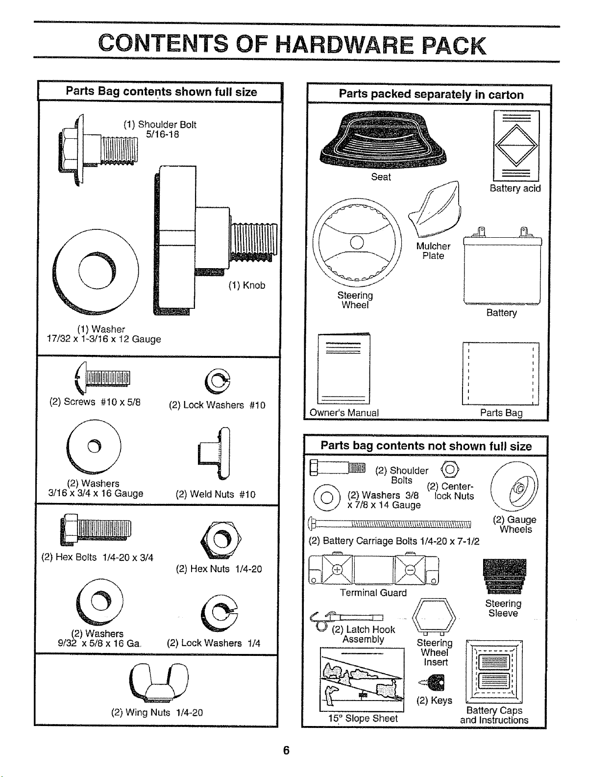
Parts Bag contents shown full size
(1) Shoulder Bolt
5/16-18
,_.,.---.--q
Parts packed separately in carton
O
Seat
Battery acid
Mulcher
Plate
17/32 x I-3/t6 x 12 Gauge
(1) Washer
(2) Screws #10 x 5/8
(2) Washers
3/16 x 3/4 x 16 Gauge
........... ,,,,,,,,,,
(2) Hex Bolts 1/4-20 x 3/4
(1) Knob
J
@
(2) Lock Washers #10
(2) Weld Nuts #10
H nnnl nl
@
(2) Hex Nuts 1/4-20
Steering
Wheel
Owner's Manual Parts Bag
Parts bag contents not shown full size
-_(2) Washers 3/8 (2) Center-
__ (2) Gauge
(2) Battery Carriage Bolts 1/4-20 x 7-t/2
(2) ShoulderBotts@ /_
x 7/8 x 14 Gauge
lock Nuts
Battery
Wheels
(b
(2) Washers
9/32 x 5/8 x t6 Ga
(2) Wing Nuts 1/4-20
(2) Lock Washers i/4
Terminal Guard
Steering
Sleeve
AssemblyStee.ng[l l]
15° Slope Sheet and Instructions
Wheel _ I
(2) Keys
Battery Caps
ill
J

ASSEMBLY
,lllllllIMI I'1 I I I ................................................ II IIIII I I
Your new tractor has been assembled at the factory with exception of those parts left unassembled for shipping purposes..
To ensure safe and proper operation of your tractor, all parts and hardware you assemble must be tightened securely. Use
the correct tools as necessary to insure proper tightness.
TOOLS REQUIRED FOR ASSEMBLY
A socket wrench set will make assembly easier. Standard
wrench sizes are listed.
(1) 9/16" wrench
(1) 1/2" wrench
Utility knife
Tire pressure gauge
When right and left hand is mentioned in this manual, it
means when you are in the operating position (seated
behind the steering wheel).
(2) 7/16'! wrench
(1) 3/4" socket w/drive
ratchet
(t) Phillips Screwdriver
TO REMOVE TRACTOR FROM CARTON
UNPACK CARTON
• Remove all accessible loose parts and parts cartons
from carton (See page 6).
• Cut, from top to bottom, along lines on al! four corners
of carton, and lay panels fiat°
• Check for any additional loose parts or cartons and
remove
BEFORE ROLLING TRACTOR OFF SKID
ATTACH STEERING WHEEL (See Fig. 1)
• Remove Iocknut and large flat washer from steering
shaft°
• Position front wheels of the tractor so they are pointing
straight forward.
• Slide the steering sleeve over the steering shaft°
. Position steering wheel so cross bars are horizontal
(left to right) and slide onto adapter.
• Secure steering wheel to steering shaft with Iocknut
and large fiat washer previously removed. Tighten
securely.
° Snap steering wheel insert into center of steering
wheel.
° Remove protective plastic from tractor hood and grill°
IMPORTANT: CHECK FOR AND REMOVE ANY STAPLES
IN SKID THAT MAY PUNCTURETIRES WHERE TRACTOR
IS TO ROLL OFF SKID.
STEERINGWHEEL
INSERT
LOCKNUT
I LARGEFLAT
' WASHER
STEERING WHEEl
STEERING
/ /
/
FIG. 1
TO ROLL TRACTOR OFF SKID (See Fig. 8)
• Raise attachment lift lever to its highest position.
• Release parking brake by depressing clutch/brake
pedal
• Place freewheel control in freewheeling position to
disengage transmission (See "TO TRANSPORT" in
Operation section of this manual)°
• Roll tractor backwards off skid°
° Remove banding holding discharge guard up against
tractor°

ASSEMBLY
= = ,H H== =, = ,i,,=,=r,=H=,, ,=
HOW TO SET UP YOUR TRACTOR
PREPARE BATTERY (See Fig. 2)
CAUTION: Wear eye and face shield.
Wash hands or clothing immediately if
_ accidentally in contact with battery acid.
Your tractor has a battery charging system which issuffi_
cient for normal use. However, periodic charging of the
battery with an automotive charger will extend its life_
• See instructions packed with vent caps in parts bag,
• Fill battery with acid, Fill each cell until it reaches the
bottom of the vent wells, Do not overfill
° Allow battery to stand and settle for at least thirty
minutes,, After standing, check the battery cell acid
level, If below the vent wells, add more acid until the
correct level is reached.,
While battery is standing (after adding acid) and later, while
battery is being charged, continue with assembly oftractor,,
IMPORTANT: TO MAXIMIZE THE LIFE OF YOUR
BATTERY, IT IS NECESSARY THAT THE BATTERY BE
CHARGED BEFORE USE, FAILURE TO CHARGE
BATTERY CAN RESULT IN A SHORTENED BATTERY
LIFE,
o Charge battery at a rate of 6 amperes for 1 hour, Use
a 12 volt battery charger. Observe all safety precau-
tions required for battery charging°
• Check the acid level after the battery is charged, tf the
acid has fallen below the correct level, add distilled or
iron free water.
• Install the vent caps to cover the vent wetts. Wash the
top of the battery with water to remove any acid, then
wipe dry.
• Check battery case for leakage to make sure that no
damage has occurred in handling.
- Dispose of excess battery acid. Neutralize acid for
disposal by adding it to two gallons of water in a five
gallon plastic container. Stir with a wooden or plastic
paddle while adding baking soda until the addition of
more soda causes no more foaming.
° Follow instructions on how to install battery.
CUT AWAY VIEW VENTCAP
_ ATTERY
Do not smoke. Fumes from charged
battery acid are explosive.
Read the instructions included with the
battery vent caps, Always wear gloves,
clothing and goggles to protect your
hands, skin and eyes.
. ,i,=l===,l== ,ll,i IHHI =N=l=
FIG. 2 8
,,,,,,,,,,,,,,,,,,,,,, ,,
VENT WELL
CELL ACID
LEVEL
I=H= =H == = ,=,ll=r,ll ,= ,
INSTALL SEAT (See Fig. 3)
Adjust seat before tightening adjustment knob.
o
Remove cardboard packing on seat pan
o
Place seat on seat pan and assemble shoulder bott..
o
Assemble adjustment knob and flat washer loosely.
Do not tighten.
° Tighten shoulder bolt securely,
• Lower seat intooperating position and sit on seat.
• Slide seat until a comfortable position isreached which
allows you to press clutch/brake pedal al! the way
down.,
o Get off seat without moving its adjusted position.
. Raise seat and tighten adjustment knob securely.
SEAT
SEAT PAN \_
SHOULDER
BOLT
FLAT WASHER
ADJUSTMENT
KNOB
FIG. 3
CHECK TIRE PRESSURE
The tires on your tractor were overinflated at the factory for
shipping purposes_ Correct tire pressure is important for
best cutting performance.,
o Reduce tire pressure to PSi shown in "PRODUCT
SPECIFICATIONS" on page 3 of this manual.
CHECK DECK LEVELNESS
For best cutting results, mower housing should be properly
leveled. See 'q'O LEVEL MOWER HOUSING" in the
Service and Adjustments section of this manual
CHECK FOR PROPER POSITION OF ALL
BELTS
See the figures that are shown for replacing motion and
mower blade drive belts in the Service and Adjustments
section of this manual, Verify that the belts are routed
correctly°
CHECK BRAKE SYSTEM
After you learn how to operate your tractor, check to see
that the brake is properly adjusted_ See "TO ADJUST
BRAKE" in the Service and Adjustments section of this
manual.
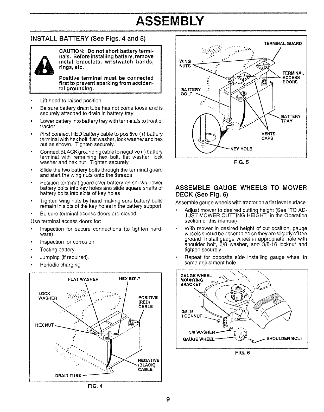
CAUTION: Do not short battery termi-
TERMINAL GUARD
metal bracelets, wristwatch bands,
rings, etco
nalso Beforeinstaliing battery, remove
Positive terminal must be connected
first to prevent sparking from acciden..
ta] grounding.
• Lift hood to raised position
• Be sure battery drain tube has not come loose and is
securely attached to drain in battery tray
• Lower battery into battery tray with terminals to front of
tractor
• First connect RED battery cable to positive (+) battery
terminal with hex bolt, flat washer, lock washer and hex
nut as shown, Tighten securely
Connect BLACK grounding cable to negative (-) battery'
terminal with remaining hex bolt, flat washer, lock
washer and hex nut Tighten securely
• Slide the two batter! bolts through the terminal guard
and start the wing nuts onto the threads
• Position terminal guard over battery as shown, lower
battery bolts into key holes and slide square shafts of
battery bolts into slots of key holes
• Tighten wing nuts by hand making sure battery bolts
remain in slots of the key holes in the battery support
• Be sure terminal access doors are closed,
Use terminal access doors for:
• Inspection for secure connections (to tighten hard-
ware)
• Inspection for corrosion
• Testing battery
• Jumping (if required)
• Periodic charging
WING
NUTS
TERMINAL
ACCESS
DOORS
BATTERY
TRAY
VENTS
CAPS
FIG. 5
ASSEMBLE GAUGE WHEELS TO MOWER
DECK (See Fig. 6)
Assemble gauge wheels with tractor on a flat level surface
• Adjust mower to desired cutting height (See "TO AD-
JUST MOWER CUTTING HEIGHT in the Operation
section of this manual)
• With mower in desired height of cut position, gauge
wheels should be assembled so they are slightly off the
ground. Install gauge wheel in appropriate hote with
shoulder bolt, 3/8 washer, and 3/8-16 Iocknut and
tighten securely
• Repeat for opposite side installing gauge wheel in
same adjustment hole
FIG, 4
GAUGEWHEEL
MOUNTING
BRACKET
3/8-16
FIG. 6
9
ASSEMBLY
i,i1,,iii, iiiii ii i,iil,l,ll,,,lllllll ii i
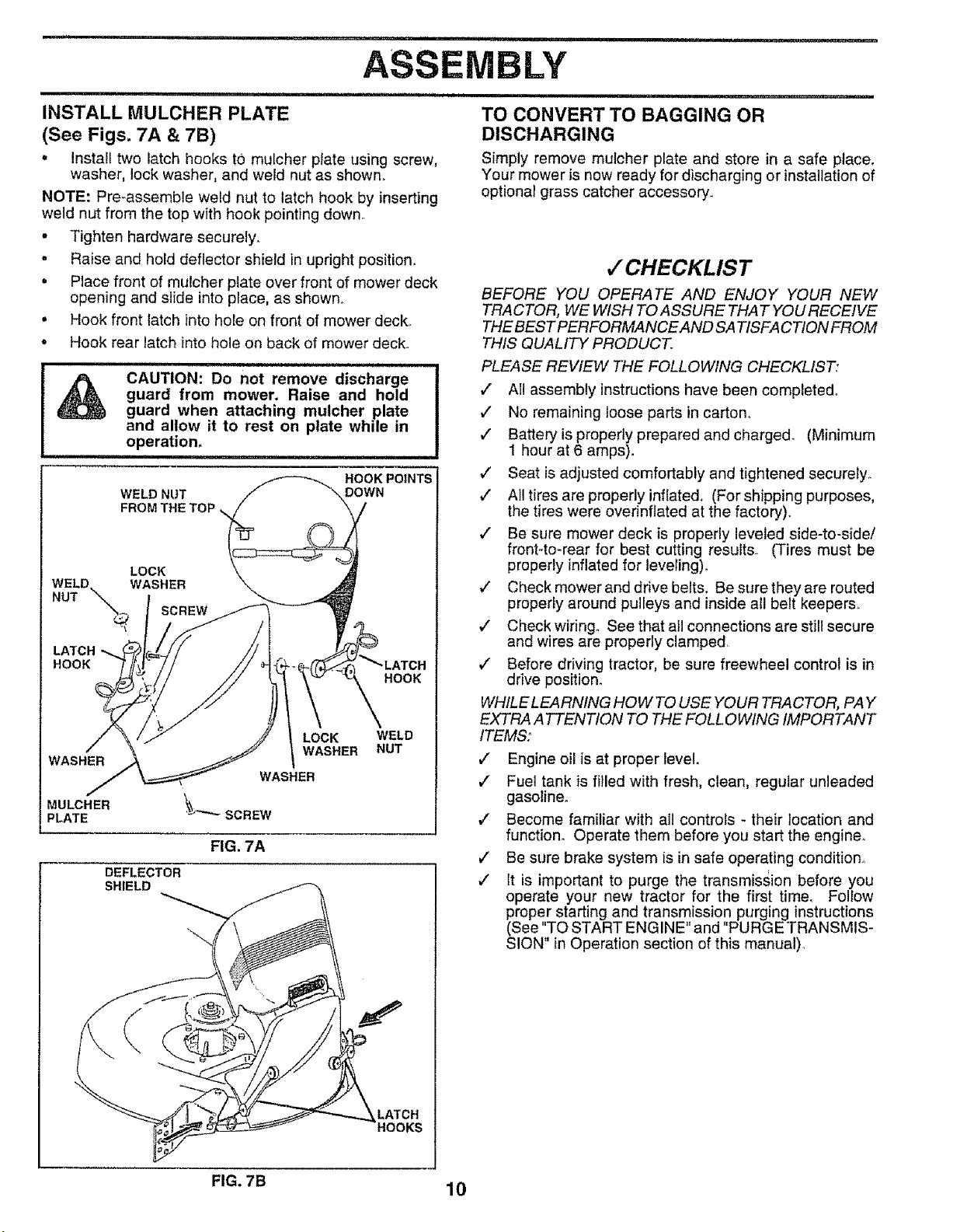
INSTALL MULCHER PLATE
(See Figs. 7A & 7B)
• Install two latch hooks to) mulcher plate using screw,
washer, lock washer, and weld nut as shown.
NOTE: Pre-assemble weld nut to latch hook by inserting
weld nut from the top with hook pointing down.
° Tighten hardware securely.
o Raise and hold deflector shield in upright position.
• Place front of mulcher plate over front of mower deck
opening and slide into place, as shown°
• Hook front latch into hole on front of mower deck,
o Hook rear latch into hole on back of mower deck.
CAUTION: Do not remove discharge
guard from mower. Raise and hold
guard when attaching mulcher plate
and allow it to rest on plate while in
operation°
WELD NUT
FROM THE TOP
WELD. WASHER
LOCK
NUT "\
\_ SCREW
LATCH _-..
HOOK
WASHER
MULCHER \_')*"_'_ SCREW
PLATE
FIG. 7A
DEFLECTOR
SHIELD
WASHER
HOOK POINTS
ii ..................
TO CONVERT TO BAGGING OR
DISCHARGING
Simply remove mulcher plate and store in a safe place.
Your mower is now ready for discharging or installation of
optional grass catcher accessory.
,/CHECKLIS T
BEFORE YOU OPERATE AND ENJOY YOUR NEW
TRACTOR, WE WISH TO ASSURE THAT YOU RECEIVE
THE BEST PERFORMANCE AND SA TISFA C TION FROM
THIS QUALITY PRODUCT.
PLEASE REVIEW THE FOLLOWING CHECKLIST:
,/ All assembly instructions have been completed.
/ No remaining loose parts in carton°
#" Battery is properly prepared and charged. (Minimum
1 hour at 6 amps).
,/' Seat is adjusted comfortably and tightened securely_
v" All tires are properly inflated, (For shipping purposes,
the tires were overinflated at the factory)_
/ Be sure mower deck is properly leveled side-to-side/
front-to-rear for best cutting results. (Tires must be
properly inflated for leveling)°
v' Check mower and drive belts. Be sure they are routed
properly around pulleys and inside all belt keepers,.
v' Check wiring. See that all connections are still secure
and wires are properly clamped.
,/ Before driving tractor, be sure freewheel control is in
drive position_
WHtLELEARNING HOWTO USE YOUR TRACTOR, PAY
EXTRA ATTENTION TO THE FOLLOWING IMPORTANT
ITEMS:
,/ Engine oil is at proper level.
,/ Fuel tank is filled with fresh, clean, regular unleaded
gasoline_
/ Become familiar with all controls - their location and
function. Operate them before you start the engine,
/ Be sure brake system is in safe operating condition°
/ It is important to purge the transmission before you
operate your new tractor for the first time, Follow
proper starting and transmission purging instructions
(See "TO START ENGINE" and "PURGE TRANSMIS-
SION" in Operation section of this manual).
FIG. 7B 10

,I,HIIIII ii iiii i iiiii ii ii i iiillllllll iiii iiilllllllll, ,i i, i i, ii
OPERATION
HI IIII ,,IHIIIIIIIII II III :::::::::::::::::::::I I HNIIINIIIII I III
KNOW YOUR TRACTOR
READ THIS OWNER'S MANUAL AND SAFETY RULES BEFORE OPERATING YOUR TRACTOR
Compare the illustrations with your tractor to familiarize yourself with the locations of various controls and adjustments_ Save
this manual for future reference,
THROTTL_CHOKE
CONTROL
LIGHTSWITCH _
CLUTCHtBRAKEPEDAL
ATTACHMENT CLUTCH LEVER
IGNITION SWITCH
LIFT LEVER
ATTACHMENT LIFT
LEVER
PARKING BRAKE
MOTION CONTROL
LEVER
FREEWHEEL
CONTROL
Our tractors conform to the safety standards of the American National Standards Institute.
ATTACHMENT CLUTCH LEVER: Used to engage the
mower blades, or other attachments mounted to your
tractor.
LIGHT SWITCH: Turns the headlights on and off,
THROTTLE/CHOKE CONTROL: Used for starting and
controlling engine speed,.
.- CLUTCH/BRAKEPEDAL: Used fordeclutchingand brak-
ing the tractor and starting the engine_
PARKING BRAKE LEVER: Locks clutch/brake pedal into
the brake position°
FIG, 8
HEIGHT ADJUSTMENT KNOB: Used to release attach-
ment lift lever when changing its position.,
MOTION CONTROL LEVER: Selects the speed and
direction of tractor.
LIFT LEVER PLUNGER: Used to release attachment lift
fever when changing its position,,
ATTACHMENT LIFT LEVER: Used to raiseand lower the
mower deck or other attachments mounted to your tractor.
IGNITION SWITCH: Used for starting and stopping the
engine,
FREEWHEEL CONTROL: Disengages transmission for
pushing or slowly towing the tractor with the engine off,
11

OPERATION
IrHHH ,n " 'n', "1 I ,,,H,H n'
The operation of any tractor can result in foreign objects thrown into the eyes, which
_._ can result in severe eye damage. Always wear safety glasses or eye shields while
.... '""'"'" ' ' i,==,=1,,,m, i n ,,nHu HI
operating your tractor or performing any adjustments or repairs. We recommend a wide
vision safety mask for over the spectacles or standard safety glasses.
HOW TO USE YOUR TRACTOR . Turn ignition key to "OFF" position and remove key.
TO SET PARKING BRAKE (See Fig. 9)
Your tractor isequipped with an operator presence sensing
switch_ When engine is running, any attempt by the
operator to leave the seat without first setting the parking
brake will shut off the engine
• Depress clutch/brake pedal into full "BRAKE" position
and holdo
• Place parking brake lever in "ENGAGED" position and
release pressure from clutch/brake pedal. Pedal should
remain in "BRAKE" position, Make sure parking brake
will hold vehicle secure.
ATTACHMENT CLUTCH LEVER
"ENGAGED" POSITION
IGNITION KEY_
THROTTL_ "ENGAGED"
CHOKE POSITION
OONTROL_-_.
LEVER
CLUTCHtBRAKE HEIGHT PARKING BRAKE
PEDAL "DRIVE" ADJUSTMENT "DISENGAGED"
POSITION KNOB POSITION
"DISENGAGED"
PARKING BRAKE
MOTION
CONTROL
LEVER
FIG. 9
STOPPING (See Fig. 9)
MOWER BLADES -
° Move attachment clutch lever to "DISENGAGED" po-
sition.
GROUND DRIVE -
• Depress clutch/brake pedal into full "BRAKE" position.
"_ .Move motion control lever to ne.utral (N) position .....
IMPORTANT: THE MOTION CONTROL LEVER DOES
NOT RETURN TO NEUTRAL (N) POSITION WHEN THE
CLUTCH/BRAKE PEDAL IS DEPRESSED
ENGINE -
• Move throttte control to slow (,,_) position.
NOTE: Failure to move throttle control to slow (,te_)
position and allowing engine to idle before stopping may
cause engine to "backfire".
Always remove key when Ieaving tractor to prevent
unauthorized use.
• Never use choke to stop engine.
NOTE: Under certain conditions when tractor is standing
idle with the engine running, hot engine exhaust gases may
cause "browning" of grass.. To eliminate this possibility,
aiways stop engine when stopping tractor on gross areas.
,,lU,,,,,nn ,i i i
pletely, as described above, before leav-
CAUTION: Always stop tractor com-
ing the operator's position; to empty
grass catcher, etc.
:::::::::::::::::::::: H i
TO USE THROTTLE CONTROL (See Fig. 9)
Always operate engine at full throttle.
. Operating engine at less than full thlottle reduces the
battery charging rate.
Full throttle offers the best bagging and mower perfor-
mance.
TO MOVE FORWARD AND BACKWARD
(See Fig. 9)
The direction and speed of movement iscontrolled by the
motion control lever,
* Start tractor with motion control lever in neutral (N)
position.
• Release parking brake and clutch/brake pedal.
, Slowly move motion control lever to desired position_
TO ADJUST MOWER CUTTING HEIGHT
(See Fig. 9)
The cutting height is controfted by turning the height adjust-
ment knob in desired direction.
• Turn knob clockwise (r_) to raise cutting height.
• Turn knob counterclockwise (I,---'_)to lower cutting
height,
The cutting height range is approximately 1-'1/2" to 4", The
heights are measured from the ground to the blade tip with
the er_gine not running. These height§are alspr6xirfiate
and may vary depending upon soil conditions, height of
grass and types of grass being mowed,
• The average lawn should be cut to approximately 2-1/2
inches during the cool season and to over 3 inches
during hot months, For healthier and better looking
lawns, mow often and after moderate growth.
• For best cutting performance, grass over 6 inches in
height should be mowed twice_ Make the first cut
relatively high; the second to desired height°
12

i ii1,,,,,,,,,,,,,,,,, ,, ,,,, .....................................
OPERATION
iiii1_,,;,,,,,,,,,,,,,,,,, ,, .............................
TO OPERATE MOWER (See Fig. 10)
Your tractor isequipped with anoperator presence sensing
switch. Any attempt by the operator to Ieave the seat with
the engine running and the attachment clutch engaged will
shut off the engine
. Select desired height of cut+
• Lower mower with attachment lift control,
- Start mower blades by engaging attachment clutch
control+
• TO STOP MOWER BLADES - disengage attachment
clutch control.
without either the entire grass catcher,
CAUTION: Do not operate the mower
on mowers so equipped, or the dis-
charge guard in place.
ATTACHMENT CLUTCH LEVER
"DISENGAGED" POSITION "ENGAGED"
POSITION
ATTACHMENT
5R
HIGH POSITION
LOW
POSITION
• Slowly move motion control [ever to slowest setting
• Make all turns slowly.
TO TRANSPORT (See Figs. 8 and 11)
When pushing or towing your tractor, be sure to disengage
transmission by placing freewheel control in freewheefing
position. Free wheet control is located at the rear drawbar
of tractor,
• Raise attachment lift to highest position with attach-
ment liftcontrol°
• Pull freewheel control knob out and hold in position by
inserting retainer spring into forward hole of control rod+
o Do not push or tow tractor at more than two (2) MPH+
• To reengage transmission, reverse above procedure,.
NOTE: To protect hood from damage when transporting
your tractor on atruck or a trailer, be sure hood is closed and
secured to tractor. Use an appropriate means of tying hood
to tractor (rope, cord, etc+)+
FIG+10
TO OPERATE ON HILLS
i_ CAUTION: Do not drive up or down
i
• Choose the slowest speed before starting up or down
hills,
• Avoid stopping or changing speed on hills,
...... If stowing is necessary, move throttle control lever to
slower pos[tion.
• tf stopping is absolutely necessary, push clutch/brake
pedal quickly to brake position and engage parking
brake,
• Move motion control lever to neutral (N) position
IMPORTANT: THE MOTION CONTROL LEVER DOES
NOT RETURN TO NEUTRAL (N) POSITION WHEN THE
CLUTCH/BRAKE PEDAL IS DEPRESSED..
- To restart movement, slowly release parking brake and
clutch/brake pedal
hills with slopes greater than 15° and
do not drive across any slope.
FIG. 11
BEFORE STARTING THE ENGINE
CHECK ENGINE OIL LEVEL (See Fig. 18)
• The engine in your tractor has been shipped, from the
factory, already filled with summer weight oil.
• Check engine oil with tractor on level ground.
- Unthread and remove oil fill cap/dipstick; wipe oil off.
Reinsert the dipstick into the tube and rest oil fill cap on
the tube° Do not thread the cap onto the tube. Remove
and read oil level+ If necessary, add oil until "FULL
mark on dipstick is reached. Do not overfill
• For cold weather operation you should change oil for
easier starting (See "OIL VISCOSITY CHART" in the
Customer Responsibilities section of this manual).
• To change engine oil, see the Customer Responsibili-
ties section in this manual°
13

_.;.... ,....................... i 1,1,1,1ii ,i,¸
OPERATION
ADD GASOLINE
,, Fill fuel tank Use fresh, clean, regular unleaded
gasoline,. (Use of leadedgasoline will increase carbon
and lead oxide deposits and reduce valve life).
IMPORTANT; WHEN OPERATING IN TEMPERATURES
BELOW 32°F(0°C), USE FRESH, CLEAN WINTER GRADE
GASOLINE TO HELP INSURE GOOD COLD WEATHER
STARTING
WARNING: Experience indicates that alcohol blended
fuels (called gasohol or using ethanol or methanol) can
attract moisture which leads to separation and formation of
acids during storage. Acidic gas can damage the fuel
system of an engine while in storage. To avoid engine
problems, the fuel system should be emptied before stor-
age of 30 days or longer. Drain the gas tank, start the
engine and Iet it run until the fuel lines and carburetor are
empty. Use fresh fuel next season. See Storage Instruc-
tions for additional information,. Never use engine or
carburetor cleaner products in the fuel tank or permanent
damage may occur.
......................................... i,i ,11111i i
filler neck. Do not overfill. Wipe off any
CAUTION: Fill to bottom of gas tank
spilled oil or fuel. Do not store, spill or
use gasoline near an open flame.
TO START ENGINE (See Fig. 9)
When starting engine for the first time or if engine has run
out of fuel, it will take extra cranking time to move fuel from
the tank to the engine.
• Depress clutch/brake pedal and set parking brake.
• Place motion control lever in neutral (N) position.
= Move attachment clutch to "DISENGAGED" position..
= Move throttle control lever to choke (N) position for
cold engine start° Forwarm engine start, move throttle
control to fast (,_) position..
• insert keyintoignition andturn key clockwiseto"START"
position and release key as soon as engine starts. Do
not run starter continuously for more than fifteen
seconds per minute. If engine does not start after
several attempts, move throttle control to fast (,_)
position, wait a few minutes and try again,
o When engine starts, slowly move throttle control lever
to desired running speed..
• Allow engine to warm up for a few minutes before
engaging drive or attachments.
NOTE: If at a.high altitude (above 3000 feet) or in cold
temperatures (below 32°F), the carburetor fuel mixture
may need to be adjusted for best engine performance.. See
'q'O ADJUST CARBURETOR" in the Service and Adjust-
ments section of this manual.
,11,,,
PURGE TRANSMISSION
,,IliL ..............................
J A CAUTION: Neverengageordisengage !
I _ freewheel lever while the engine is run-
I nin,g,:..........
To ensure proper operation and performance, it is recom-
mended that the transmission be purged before operating
tractor for the first time, This procedure will remove any
trapped air inside the transmission which may have deveF
oped during shipping of your tractor.
IMPORTANT: SHOULD YOUR TRANSMISSION REQUIRE
REMOVAL FOR SERVICE OR REPLACEMENT, IT
SHOULD BE PURGED AFTER REINSTALLATtON
BEFORE OPERATING THE TRACTOR.
• Place tractor safely on level surface with engine off and
parking brake set.
. Disengage transmission by placing freewheel control
in freewheeling position (See "TO TRANSPORT" in
this section of manual).
° Sitting inthetractorseat, start engine. Afterthe engine
isrunning, move throttle control to slow (,_) position.
With motion control lever inneutral (N) position, slowly
disengage clutch/brake pedal.
o Move motion control lever to full forward position and
hold for five (5) seconds. Move lever to full reverse
position and hold for five (5) seconds. Repeat this
procedure three (3) times°
NOTE: During this procedure there will be no movement of
drive wheels. The air isbeing removed from hydraulic drive
system_
• Move motion control lever to neutral (N) position. Shut-
off engine and set parking brake.
• Engage transmission by placing freewheel control in
driving position (See "TO TRANSPORT" in this section
of manual).
• Sitting in the tractor seat, start engine° After the engine
is running, move throttle control to half (1/2) speed.
With motion control lever in neutral (N) position, slowly
disengage clutch/brake pedal,
° Slowly move motion control lever forward, after the
tractor moves approximately five (5) feet, slowly move
motion control lever to reverse position,. After the
tractor moves approximately five (5) feet return the
motion control lever to the neutral (N) position. Repeat
this procedure with the motion control lever three (3)
times.
° Your tractor is now purged and now ready for normal
operation.
I
14

OPERATION
MOWING TIPS
• Tire chains cannot be used when the mower housing
is attached to tractor.
• Mower should be,properly leveled for best mowing
performance. See TO LEVEL MOWER HOUSING" in
the Service and Adjustments section of this manual
• The left hand side of mower should be used for trim-
ming.
= Drive so that clippings are discharged onto the area
that has been cut. Have the cut area to the right of the
machine. This will result in a more even distribution of
clippings and more uniform cutting.
o When mowing large areas, start by turning to the right
so that clippings will discharge away from shrubs,
fences, driveways, etco After one or two rounds, mow
in the opposite direction making left hand turns until
finished (See Fig. 12 ),1
o If grass is extremely tall, it should be mowed twice to
reduce load and possible fire hazard from dried clip-
pings. Make first cut relatively high; the second to the
desired height.
• Do not mow grass when itis wet. Wet grass will plug
mower and leave undesirable clumps. Allow grass to
dry before mowingr
• Always operate engine at full throttle when mowing to
assure better mowing performance and proper dis-
charge of material Regulate ground speed by select-
ing a low enough gear to give the mower cutting
performance as well as the quality of cut desired.
o When operating attachments, select a ground speed
that will suit the terrain and give best performance of
the attachment being used.
MULCHSNG IV1OWING TiPS
IMPORTANT: FOR BEST PERFORMANCE, KEEP
MOWER HOUSING FREE OF BUILT-UP GRASS AND
TRASH CLEAN AFTER EACH USE.
. The special mulching blade will recur the grass clip-
pings many times and reduce them in size so that as
they fall onto the lawn they witl disperse intothe grass
and not be noticed. Also, the mulched grass will
biodegrade quickly to provide nutrients for the lawn.
Always mulch with your highest engine (blade) speed
as this wilt provide the best recutting action of the
blades.
• Avoid cutting your lawn when it iswet. Wet grass tends
to form clumps and interferes with the mulching action..
The best time to mow your lawn is the early afternoon.
At this time the grass has dried and the newly cut area
will not be exposed to the direct sun.
• For best resuits, adjust the mower cutting height so that
the mower cuts off only the top one-third of the grass
blades (See Fig. 13).. For extremely heavy mulching,
reduce your width of cut on each pass and mow slowly..
• Certain types of grass and grass conditions may re=
quire that an area be mulched a second time to com-
pletety hide the clippings. When doing a second cut,
mow across or perpendicular to the first cut path..
- Change your cutting pattern from week to week. Mow
north to south one week then change to east towest the
next week This wiil help prevent matting and graining
of the lawn.
MAX 113
f
l
FIG. 13
C" "
FIG. 12
15

_ ii,u, iiiiiiii1,,i ................111111, i,iii i ..................... i ii, ,,,,......... ,, ,, ,,,
CUSTOMER RESPON BILmES
MAINTENANCE SCHEDULE
FILL IN DATES
AS YOU COMPLETE
REGULAR SERVICE SERVICE DATES
Check Brake Operation If if I I
Check Tire Pressure if' If ,I
T Check for Loose Fasteners If I tf 1
:R Sharpen!Replace Mower Blades ' _4_'4 ......... I
{_ Lubrication Chart I_ 6,/
T Check Battery Level/Recharge V"
0 Clean Battery and Terminals If 6,/ '
R CheckTransaxle Cooling I_
Adjust Blade Belt(s) Tension '................. _5 i ......i
Adjust Motion Drive Belt(s) Tension 1_5 I
.......,' ,........ : : : :: :
Check Engine Oil Level !/ _/ !
Change Engine O!,!.... _4' _1,_,3 V"
Clean Air Filter V'_
N Clean Air Screen
G Inspect Muffler/Spark Arrester
I Replace Oil Filter (If equipped)
NE Clean Engine Cooling
Replace Spark Plug
Replace Air Filter Paper Cartridge
Replace Fuel Filter
1 - Change more often when operating under a heavy toad or in high ambient temperatures
2 - Service more o_'ten when operaling in diriy or dusfy conditions
Fins
L Z
=
l
v"
V'2 ...... '
......!v'
3 ,.if equipped with oll fitter, change oil every 50 hours
4. Repiace blades more often when mowing in sandy soil
5 - If equipped with adjustable system
GENERAL RECOMMENDATIONS
The warranty on this tractor does not cover items that have
been subjected to operator abuse or negligence. To
receive full value from the warranty, operator must maintain
tractor as instructed in this manual
Some adjustments will need to be made periodically to
properly maintain your tractor
All adjustments in the Service and Adjustments section of
this manual should be checked at least once each season°
Once a year you should replace the spark plug, clean
or replace air filter, and check blades and belts for
wear- A new spark plug and clean air filter assure
proper air-fuel mixture and help your engine run better
and last tonger,
BEFORE EACH USE
• Check engine oil level
• Check brake operation..
• Check tire pressure°
, Check for loose fasteners.
LUBRICATION CHART
(_SPINDLE ZERK--.__ _[_ SPINDLE ZERK (_)
( )FRONTWREEL ........ V[ ""_'pFRONT WHEEL(_
BEARING ZERK _ l I _ BEARING ZERK
Q
CLUTCH PIVOT
(_)SAE 30 MOTOR OIL API - SG
(_)GENERAL PURPOSE GREASE
(_) REFER TO CUSTOMER RESPONSIBILIT|ES "ENGINE" SECTION
IMPORTANT: DO NOT OIL OR GREASE THE PIVOT POINTS,
WHICH HAVE SPECIAL NYLON BEARINGS VISCOUS LUBRi-
CANTS WILL ATTRACT DUST AND DIRT THAT WILL SHORTEN
THE LIFE OF THE SELF-LUBRICATING BEARINGS. IF YOU
FEEL THEY MUST BE LUBRICATED, USE ONLY A DRY, POW _
16 DERED GRAPHITE TYPE LUBRICANT SPARINGLY
®

============= === = == i= i ..................................
CUSTOMER RESPONSIBILITIES
TRACTOR • To check blade batancel you will need a 5/8" diameter
Always observe safety rules when performing any mainte-
nanceo
BRAKE OPERATION
tf tractor requires more than six (6) feet stopping distance
at high speed in highest gear, then brake must be adjusted_
(See 'q'O ADJUST BRAKE" in the Service and Adjust-
ments section of this manual).
TIRES
- Maintain proper air pressure in all tires (See "PROD-
UCT SPECIFICATIONS" on page 3 of this manual).
• Keep tires free of gasoline, oil, or insect control chemi-
cals which can harm rubber.
• Avoid stumps, stones, deep ruts, sharp objects and
other hazards that may cause tire damage.
BLADE CARE
For best results mower blades must be kept sharp,, Re-
#ace bent or damaged blades,
BLADE REMOVAL (See Fig. 14)
• Raise mower to highest position to allow access to
btadeso
• Remove hex bolt, lock washer and flat washer securing
blade°
• Install new or resharpened blade with trailing edge up
towards deck as shown.
• Reassemble hex bolt, lock washer and flat washer in
exact order as shown.
• Tighten bolt securely (30-35 FtoLbs torque),
IMPORTANT: BLADE BOLT ISGRADE 8HEATTREATED.
NOTE: We do not recommend sharpening blade _but if you
do, be sure the blade is balanced.
_'_ MANDREL
BLADE _,,__..,._ ASSEMBLY
HEX BOLT (GRADE 8)*
.......... ;'AGRADE8 HEATTREATEDBOLTCANBE
IDENTIFIEDBYSIXLINESONTHEBOLTHEAD,
FIG. 14
,lllrllllllll ii iii ii i 'IIIIIHIIIII III I
steel bolt, pin, or a cone balancer_ (When using a cone
batancer, fdllow the instructions supplied with bal-
ancer).
• Slide blade on to an unthreaded portion of the steel bolt
or pin and hold the bolt or pin parallel with the ground.
If blade is balanced, it should remain in a horizontal
position. If either end of the blade moves downward,
sharpen the heavy end until the blade is balance&
NOTE: Do not use a nail for balancing blade° The lobes of
the center hole may appear to be centered, but are not.
CENTER HOLE /
518" BOLT
OR PIN
/
FIG. 15
BATTERY (See Fig. 16)
Your tractor has a battery charging system which is suffi-
cient for normal use° However, periodic charging of the
battery with an automotive charger will extend its life_
• Acid solution level ineach battery cell should be even
with bottoms of vent wells. Add only distilled orironfree
water if necessary. Do not overfill
o Keep batteryand terminals c_ean_
• Keep battery bolts tight.
• Keep vent caps tight and small vent holes in caps open..
= Recharge at 6 amperes for I hour.
TO CLEAN BATTERY AND TERMINALS
Corrosion and dirt on the battery and terminals can cause
the battery to "leak" power°
• Open battery box door°
• Disconnect BLACK battery cable first then RED bat-
tery cable and remove battery from tractor.
• Wash battery with solution of four tablespoons of
baking soda to one gallon of water. Be careful not to get
the soda solution into the cells.
• Rinse the battery with plain water and dry°
° Clean terminals and battery cable ends with wire brush
until bright,
• Coat terminals with grease or petroleum jelly.
• Reinstall battery (See "INSTALL BATTERY" in the
Assembly section of this manual).
CUT AWAY VIEW VENT CAP
TO SHARPEN BLADE (See Fig. 15)
Care should be taken to keep the blade balanced° An
unbalanced blade will cause excessive vibration and even-
tual damage to mower and engine.
• The blade can be sharpened with afile or on a grinding
wheel. Do not attempt to sharpen while on the mower.
17
.........._,, _ _VENT
i__j_ WELL
BATTERY
CELL ACID
LEVEL
FIG. 16

rl .....................................................................................
CUSTOMER RESPONSiBILiTiES
............... i i,i ,i ....................... iiiiiii, i, ii i i ,1111, ,1111 i Pill IIIIL I
TRANSAXLE COOLING TO CHANGE ENGINE OIL (See Fig, 17)
The fan and cooling fins of transmission should be kept
clean to assure proper cooling
Do not attempt to clean fan or transmission while engine is
running or while the transmission is hot,
- Inspect cooling fan to be sure fan blades are intact and
clean.
• Inspect cooling fins for dirt, grass clippings and other
materials, To prevent damage to seals, do not use
compressed air or high pressure sprayer to clean
coohng fins.
TRANSAXLE PUMP FLUID
The transaxie was sealed at the factory and fluid mainte-
nance is not required for the life of the transaxle. Should the
transaxle ever leak or require servicing, contact your near-
est authorized service center/department.
V-BELTS
Check V_belts for deterioration and wear after 100 hours of
operation and replace if necessary, The belts are not
adjustable, Replace belts if they begin to slip from wear,
ENGINE
LUBRICATION
Only use high quality detergent oil rated with AP1 service
classification SG Select the oil's SAE viscosity grade
according to your expected operating temperature_
SAE V_SOOSITY GRADES
Determine temperature range expected before oil change_
All oil must meet API service classification SG
o Be sure tractor is on level surface.
• Oil will drain more freely when warm_
, Catch oil in a suitable container.
• Remove oil fill cap/dipstick,, Be careful not to allow dirt
to enter the engine when changing oilo
. Remove drain plug,
. After oil has drained completely, replace oil drain plug
and tighten securely.
- Refill engine with oil through oil fill dipstick tube. Pour
slowly. Do not overfill For approximate capacity see
PRODUCT SPECIFICATIONS" on page 3 of this
manual.
• Use gauge on oil fill cap/dipstick for checking level,
Insert dipstick into the tube and restthe oil fill cap on the
tube. Do not thread the cap onto the tube when taking
reading Keep oil at "FULL" line on dipstick, Tighten
cap onto the tube securely when finished°
AIR CLEANER
COVER
FOAM
PRE-CLEANER
AIR CLEANER
PAPER FILL
CARTRIDGE CAP/DIPSTICK
COVER KNOB
WING NUT
RUBBER
_CLEANER
BASE
NOTE: Although multi-viscosity oils (5W30, 10W30 etc,)
improve starting in cold weather, these multi-viscosity oils
will result in increased oil consumption when used above
32°F, Check your engine oil level more frequently to avoid
possible engine damage from running low on oil,
Change the oil after the first two hours of operation and
every 50 hours thereafter orat least once ayear if the tractor
is not used for 50 hours in one year.
Check the crankcase oil level before starting the engine and
after each eight (8) hours of operation, Tighten oil fill cap/
dipstick securely each time you check the oil level.
AIR SCREEN
FIG. 17
CLEAN AIR SCREEN (See Fig. 17)
Air screen must be kept free of dirt and chaff to prevent
engine damage from overheating, Ctean with awire brush
or compressed air to remove dirt and stubborn dried gum
fibers,
18
 Loading...