

Craftsman 917257632 Owner’s Manual

MODEL 917.257632
• Assembly
eOperation
=Customer Responsibilities
®Service and Adjustments
=Repair Parts
OWNER'S MANUAL
CAUTION: Read and follow all safety rules and instructions before operating this equipment,
.............................. IIIIIIIIIIIIIIIIIIIIIIIrrmlllllllllll ............ 1 .....................

Safe Operation Practices for Ride-On Mowers
IMPORTANT: 'THIS CUTTING MACHINE IS CAPABLE OF AMPUTATING HANDS AND FEET AND THROWING OBJECTS.
FAILURE TO OBSERVE THE FOLLOWING SAFETY INSTRUCTIONS COULD RESULT IN SERIOUS INJURY OR DEATH°
SAFETY RULES
I. GENERAL OPERATION
• Read, understand, and follow ati instructions in the manual
and on the machine before starting..
,, Only allow responsible adults, who are familiar with the
instructions,to operate the machine,
• Clear the area of objects such as rocks, toys, wire, etc,
which could be picked up and thrown by the blade.
• Besure the area is clear of other people before mowing Stop
machine if anyone enters the area..
• Never carry passengers.,
• Do not mow in reverse unless absolutely necessary.. Always
look down and behind before and while backing.
• Be aware of the mower discharge direction and do not point
it at anyone. Do not operate the mower without either the
entire grass catcher or the guard in place.
° Slow down before turning.
• Never leave a running machine unattended. Always turn off
blades, set parking brake, stop engine, and remove keys
before dismounting.
• Turn off blades when not mowing.
, Stop engine before removing grass catcher or unclogging
chute..
• Mow only in daylight or good artificial light.
• Do not operate the machine while under the influence of
alcohol or drugs.,
• Watch for traffic when operating near or crossing roadways.
° Use extra care when loading or unloading the machine into
a trailer or truck.,
II. SLOPE OPERATION
Slopes are a major factor related to loss-of-controland ttpover
accidents, which can resu{t in severe injury or death_ All slopes
requireextra caution.,tf you cannotback uptheslope or ifyou feel
uneasy on it, do not mow ito
DO:
• Mow up and down slopes, not across.,
• Remove obstacles such as rocks, tree limbs, etc_
• Watch for holes, ruts, or bumps. Uneven terrain could
overturnthe machtne_ Ta// grass can hide obstac/es..
• Use slowspeed, Choose a low gear so thatyou wiltnot have
tostop or shiftwhile onthe slope
• Follow the manufacturer's recommendations for wheel
weights or counterweights to improve stability.
• Use extra care with grass catchers or other attachments.
These can change the stabilityof the machine.
° Keep all movement on the slopes slowand gradua/. Do not
make sudden changes in speed or direction.
• Avoid starting or stopping on a slope. If tires lose traction,
disengage the blades and proceed slowly straight down the
slope.
DO NOT:
• Donor turn on slopes unlessnecessary, and then,turnslowly
and gradually downhill,if possible_
° Do not mow near drop-ells, ditches, or embankments. The
mower could suddenly turn over if a wheel is over the edge
of a cliffor ditch, or if an edge caves in,.
• Do not mow on wet grass. Reduced traction could cause
sliding.
• Do not try tostabilize the machine byputtingyourfoot on the
ground.
= Do not use grass catcher on steep slopes,.
!11.CHILDREN
Tragic accidents can occur if the operator is not alert to the
presence of children..Children are often attracted tothe machine
and the mowing activity, Never assume thatchildren will remain
where you last saw them.
° Keep childrenoutof the mowingarea and under the watchful
care of another responsible aduR.
° Be alert and turn machine off if children enter the area
° Before and when backing, look behind and down for small
children.
° Never carry children, They may fall off and be seriously
injured or interfere with safe machine operation.
° Never allow children to operate the machine.
• Use extra care when approaching blind comers, shrubs,
trees, or other objects that may obscure vision.
IV, SERVICE
° Useextra care in handlinggasoline and etherfuels. They are
flammable and vapors are explosive.
Use only an approved container..
Never- remove gas cap or add fuel with the engine
running. Allow engine to cool before refueling. Do not
smoke,
Never refuel the machine indoors,
Never store the machine or fuel container inslde where
there isan open flame, such as a water hF,,ater.
• Never run a machineinside a closed area..
= Keep nuts and bolts, especially blade attachment bolts, tight
and keep equipment in good condition.
° Never tamper with safety devices. Check their proper
operationregulady_
• Keep machine free of grass, leaves, or ether'debrisbuild-up.
Clean oil or fuel spillage. Allow machine to cool before
stodng.
° Stop and inspect the equipment if you strike an object.
Repair, if necessary, before restarting,
• Never make adjustmentsor repairswiththe engine running..
,, Grass catchercomponents are subjectto wear, damage, and
deterioration, which could expose moving parts or atlow
objects to be thrown. Frequently check components and
replace withmanufacturer's recommended parts, when nec-
essary.
• Mower blades are sharp and can cut. Wrap the blade(s) or
wear gloves, and use extra caution when servicing them
• Check brake operation frequently., Adjust and service as
required,
tant safety precautions, it means
Look for this symbol to point out impor-
CAUTIONtt! BECOME ALERTIH YOUR
SAFETY IS INVOLVED,
I I'11'11 i,i i I II II II I IJ IJILI!I±III
CAUTION: Always disconnect spark
contact spark plug in order to prevent
plug wire and place wire where itcannot
accidental starting when setting up,
transporting, adjusting or making
repairs.
2

CONGRATULATIONS on your purchase of a Sears
Tractor. It has been designed, engineered and manufac-
tured to give you the best possible dependability and
performance.
Should you experience any problem you cannot easily
remedy, please contact your nearest Sears Authorized
Service CenteriDepartmento We have competent, well-
trained technicians and the proper tools to service or repair
this unit,,
Please read and retain this manual. The instructions will
enable you to assemble and maintain your unit properly,
Always observe the "SAFETY RULES"°
MODEL
NUMBER 917°257632
SERIAL
NUMBER
DATEOFPURCHASE
THE MODEL AND SERIAL NUMBERS WILL BE FOUND
ON A PLATE UNDER THE SEAT,
YOUSHOULDRECORDBOTHSERIALNUMBERAND
DATE OF PURCHASE AND KEEPIN A SAFE PLACE
FOR FUTURE REFERENCE_
PRODUCT SPECIFICATIONS
HORSEPOWER: 13.0
GASOLINE CAPACITY 5 QUARTS
AND TYPE: UNLEADED REGULAR
OIL TYPE (API-SFtSG): SAE 30 (above 32°F)
OIL CAPACITY: 3 PINTS
SPARK PLUG: CHAMPION RJ19LM
(GAP: .030") STD361458
VALVE CLEARANCE: INTAKE: .,005" - ,007"
GROUND SPEED (MPH): FORWARD:
TIRE PRESSURE: FRONT: 14 PSI
CHARGING SYSTEM: 3 AMPS BATTERY
BLADE BOLT TORQUE: 30-35 FT_LBS
SAE 5W-30 (below 32°F)
EXHAUST: .009" - .,011"
1st 1..02
2nd 1,35
3rd 2,.10
4th 3o14
5th 4_00
6th 5.12
REVERSE: 1.58
REAR: 12 PSI
5 AMPS HEADLIGHTS
MAINTENANCE AGREEMENT
A Sears Maintenance Ag reement isavailable on this prod-
ucL Contact your nearest Sears store for details_
CUSTOMER RESPONSIBILmES
,, Read and observe the safety rules°
= Follow a regularschedule in maintaining, caring for and
using your unit,.
= Follow the instructions under "Customer Responsibili-
ties" and "Storage" sections of this owner's manual
i illllll/lllllllullLll ii illll i .....I'"IHI' LI I I Lll IIIIIIIHIIIIlll I I
WARNING: This tractor is equipped with an internal
combustionengineand should not be used on or near any
unimprovedforest-covered, brush-covered or grass-cov-
ered land unless the engine's exhaust syste;,l is equipped
witha spark arrester meeting applicable local or state laws
(ifany). If a spark arrester isused, it should be maintained
in effectiveworkingorder by the operatorn
In the state of California the above is required by law
(Section4442 of the California Public Resources Code)°
Other states may have similar laws, Federal laws applyon
federaTlands,.A spark arrester for the muffler is available
through your nearest Sears Authorized Service Center/
Department (See REPAIR PARTS section ofthismanual).
LIMITED TWO YEAR WARRANTY ON ELECTRIC START RIDING EQUIPMENT
For two (2) years from the date of purchase, if this riding equipment is maintained, lubricated and tuned up according to the
instructionsin the owner's manual, Sears will repair or replace, free of charge, any parts found to be defective in material or
workmanship_
This Warranty does not cover:.
,, Expendable items which become worn during norma! use, such as blades, spark plugs, air cleaners and belts.
• Tire replacement or repair caused by punctures from outside objects, such as nails, thorns, stumps, or glass.
• Repairs necessary because of operator abuse, negligence, improper storage or accident or the failure to maintain the
equipment according to the instructions contained inthe owner's manual
• Riding equipment used for commercial or rental purposes.
LIMITED 90 DAY WARRANTY ON BATTERY
For ninety (90) days from date of purchase, if any battery included with this riding equipment proves defective in material or
workmanship and our testing determines the battery will not hold a charge, Sears will replace the battery at no charge.
WARRANT"( SERVICE tS AVAILABLE BY RETURNING THE RIDING EQUIPMENT TO THE NEAREST SEARS SERVICE
CENTEPJDEPARTMENT IN THE UNITED STATES
This Warranty gives you specific legal fights, and you may also have other rightswhich may vary from state tostate,.
SEARS, ROEBUCK AND CO.., D/817 WA, HOFFMAN ESTATES, ILLINOIS 60179
............................. ,,, , , iHi
3
U_I L. lJ t )WJII3UUIIIIIIIIIIIIIIIIIIIIIIIIIIIII, 111111111 : : : : 11111111111 111111111111111111111111111 1111111111) IIIII IIIIIII IIIIIIIIIII I I I III
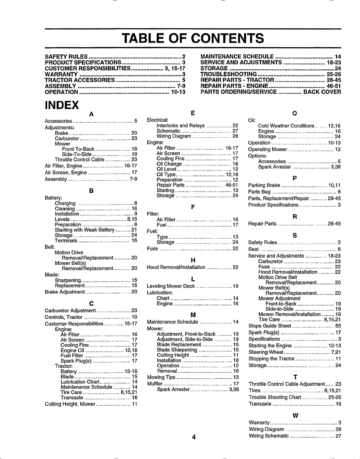
TABLE OF CONTENTS
SAFETY RULES ............................................................ 2
PRODUCT SPECIFICATIONS ...................................... 3
CUSTOMER RESPONSIBILITIES ..................... 3, 15-17
WARRANTY .................................................................. 3
TRACTOR ACCESSORIES .......................................... 5
ASSEMBLY ............................................................... 7,.9
OPERATION .......................................................... !0-13
INDEX
A
Accessories ..........................................................5
Adjustments:
Brake .....................................................20
Carburetor ............................................23
Mower
Front-To-Back .............................19
Side-To-Side ...................................19
Throttle Control Cable ....................23
Air Filter, Engine .........................................16-17
Air Screen, Engine .......................................17
Assembly ...........................................................7-9
B
Battery:
Charging .............................................................8
Cleaning ..................................................16
Installation................................................9
Levels................................................8,15
Preparation ............................................8
Stading with Weak Battery ........... 2t
Storage ................................................24
Terminals ................................................16
Belt:
Motion Drive
RemovaltReplacement ...............20
Mower Belt(s)
Removal/Replacement ............. 20
Btade:
Sharpening ............................................15
Replacement ...........................................15
Brake Adjustment .............................................20
C
Carburetor Adjustment ................................23
Controls, Tractor. .................................................10
Customer Responsibilities ......................15-17
Engine:
Air Filter.............................................16
Air Screen ...........................................17
Cooling Fins ...........................................17
Engine Oil .................................12,16
Fuel Filter ..............................................17
Spark Plug(s) ...........................................17
Tractor.
Battery ..........................................15.16
Blade ...............................................15
Lubrication Chad ............................14
Maintenance Schedule ............ 14
Tire Care ..................................8,15,2!
Transaxle ................................... 16
Cutting Height, Mower ......................... 11
Electrical:
interlocks and Relays ......................22
Schematic .............................................27
Wiring Diagram ...............................................28
Engine:
Air Filter ..............................................16-17
Air Screen ............................................17
Cooling Fins ................................... 17
Oil Change .........................................................16
Oil Level ..............................................................12
Oil Type .............................................12,16
Preparation ...........................................12
Repair Pads ...................................46-51
Starting ....................................................13
Storage ..............................................24
Filter:
Air Filter...........................................................16
Fuel ..................................................................17
Fuel:
Type .....................................................................t3
Storage .......................................................24
Fuse ........................................................................22
Hood Removal!Instaflation ....................22
Leveling Mower Deck ..............................................19
Lubrication:
Chad ...........................................................14
Engine........................................... 16
Maintenance Schedule .................................14
Mower:
Adjustment, Front-to-Back ........... 19
Adjustment, Side-to-Side .....................19
B_ade Replacement ..................................15
Blade Sharpening .................................15
Cutting Height ............................... 11
Installation ..............................................18
Operation ...................................................12
Removal .......................................... 18
Mowing Tips ........................................ 13
Muffler .....................................................................t7
Spark Arrestor ...................................3,38
MAINTENANCE SCHEDULE ..................................... 14
SERVICE AND ADJUSTMENTS ........................... 18-23
STORAGE ................................................................... 24
TROUBLESHOOTING ........................................... 25-26
REPAIR PARTS - TRACTOR ................................ 28-45
REPAIR PARTS - ENGINE .................................... 46-51
PARTS ORDERING/SERVICE ............... BACK COVER
E
Oil:
Coid Weather Conditions ............12,16
Engine ..................................................16
Storage ...............................................................24
Operation ................................................................10-13
Operating Mower .......................................12
Options:
Accessories ...........................................5
Spark Arrestor ....................................3,38
O
P
Parking Brake .........................................10,11
Parts Bag ....................................................6
Pads, Replacement/Repair ............ 28-45
F
Product Specifications ..................................3
R
Repair Parts ................................................28-45
S
Safety Rules ...................................................................2
Seat ........................................................................ 8
H
L
M
Service and Adjustments ..................18-23
Carburetor ..............................................23
Fuse .............................................. 22
Hood Removal/installation ..............22
Motion Drive Belt
RemovallReplacement ..............20
Mower Belt(s)
Removal/Replacement ...............20
Mower Adjustment
Front*to-Back ..............................19
Side-to-Side ............................ 19
Mower Removal/installation ............18
Tire Care .................................8,15,21
Slope Guide Sheet .......................................55
Spark Plug(s) .................................................17
Specifications ...................................................3
Starling the Engine ................................12-13
Steering Wheel .................................. 7,21
Stopping the Tractor .................................11
Storage.........................................................24
T
Throttle Control Cable Adjustment .......23
Tires ........................................................8,15,21
Trouble Shooting Chad ............................25-26
Transaxle .............................................................16
W
Warranty.................................................... 3
Wiring Diagram .................................... 28
4
Wiring Schematic ........................................27
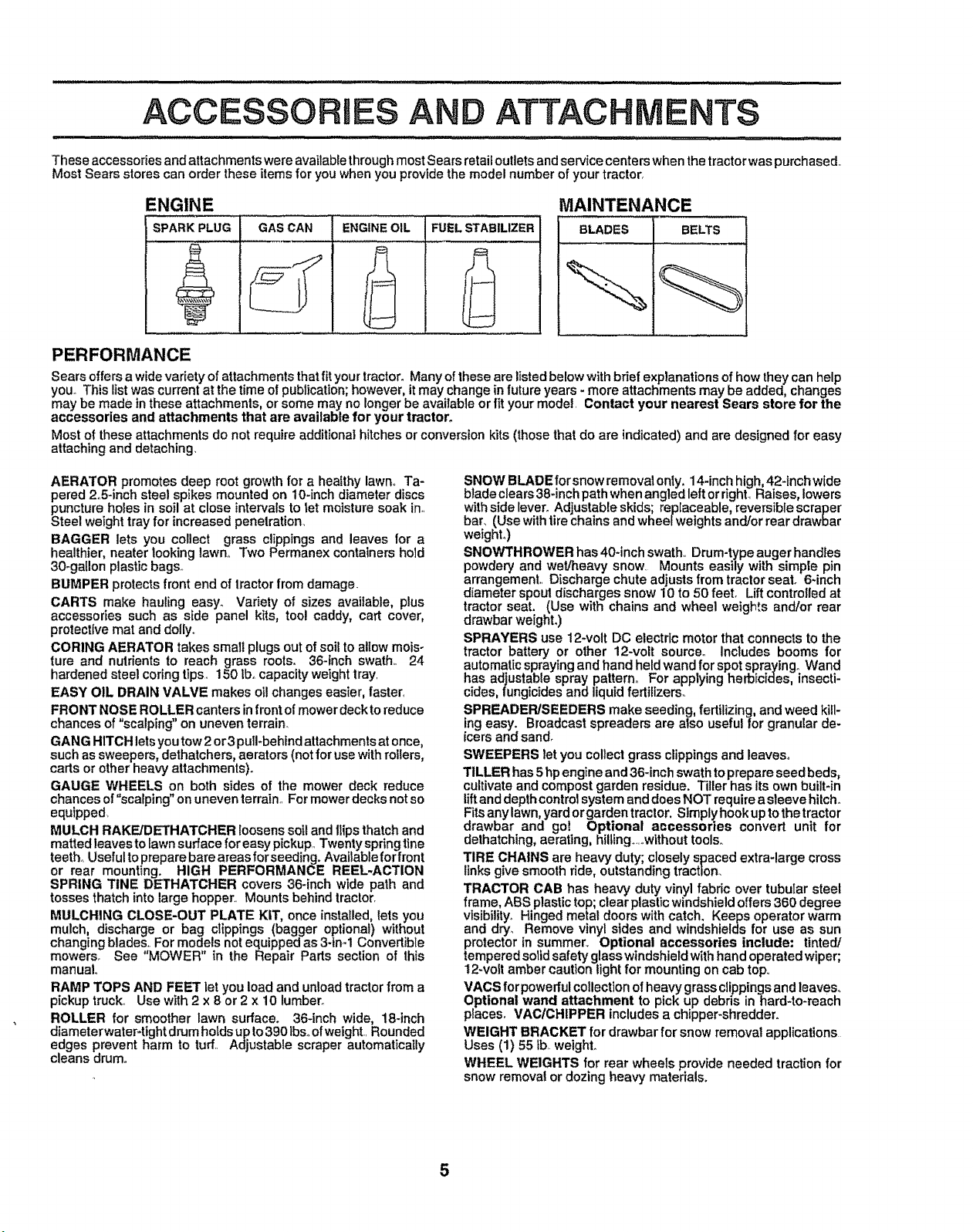
ACCESSORIES AND ATTACHMENTS
These accessories and attachments were available throughmost Sears retail outletsand service centers when the tractor waspurchased..
Most Sears stores can order these items for you when you provide the model number of your tractor.
ENGIN E MAINTENANCE
SPARK PLUG BLADES BELTS
PERFORMANCE
Sears offers a widevariety of attachments that fityour tractor. Many ofthese are listed below with brief explanations of how they can help
you_This list was current at the time of publication;however,it may change in future years - more attachments may be added, changes
may be made in these attachments, or some may no longer be available or fit your model, Contact your nearest Sears store for the
accessories and attachments that are available for your tractor.
Most of these attachments do not require additional hitches or conversion kits (those that do are indicated) and are designed for easy
attaching and detaching,
GAS CAN ENGINEOIL FUELSTABILIZER
AERATOR promotes deep root growth for a healthy lawn,. Ta-
pered 2o5-inch steel spikes mounted on 10-inch diameter discs
puncture holes in soil at close intervals to let moisture soak in.
Steel weight tray for increased penetration,
DAGGER lets you collect grass clippings and leaves for a
healthier, neater looking lawn,. Two Permanex containers hold
30_gallon plastic bags_
BUMPER protects front end of tractor from damage.
CARTS make hauling easy_ Vadety of sizes available, plus
accessories such as side panel kits, tool caddy, cart cover,
protective mat and dolly°
CORING AERATOR takes small plugs out of soil to allow mois-
ture and nutrients to reach grass roots. 36-inch swath. 24
hardened steel coring tips, 150 Ib,.capacity weight tray.
EASY OIL DRAIN VALVE makes oil changes easier, faster,
FRONT NOSE ROLLER canters infront of mower deck to reduce
chances of "scalping" on uneven terrain.
GANG HITCH lets you tow 2or3 pull-behind attachments at once,
such assweepers, dethatchers, aerators (not for use with rollers,
carts or other heavy attachments).
GAUGE WHEELS on both sides of the mower deck reduce
chances of"scalping" on uneven terrain.. For mower decks not so
equipped.
MULCH RAKE/DETHATCHER loosens soil and Ilips thatch and
matted leaves to lawnsurface for easy pickup.. Twenty spdng tlne
teeth° Useful to prepare bare areas forseeding. Avaitablefor front
or rear mounting. HIGH PERFORMANCE REEL-ACTION
SPRING TINE DETHATCHER covers 36-inch wide path and
tosses thatch into large hopper.. Mounts behind tractor.
MULCHING CLOSE-OUT PLATE KIT, once installed, lets you
mulch, discharge or bag clippings (bagger optional) without
changing blades,. For models not equipped as 3-ira1 Convertible
mowers. See "MOWER" in the Repair Parts section of this
manual.
RAMP TOPS AND FEET let you load and unload tractor from a
pickup truck,. Use with 2 x 8 or 2 x 10 lumber_
ROLLER for smoother lawn surface. 36-Inch wide, 18-inch
diameterwater-tight drum holds up to390 tbsoofweight.. Rounded
edges prevent harm to turf.. Adjustable scraper automatically
cleans drum.
SNOW BLADE for snow removalonly. 14-inch high, 42-inch wide
blade clears 38-inchpathwhen angled left orright, Raises, lowers
withside lever. Adjustable skids; replaceable, reversible scraper
bar, (Use with tirechainsand wheet weights and/or rear drawbar
weighL)
SNOWTHROWER has 40-inch swath,, Drum-typeauger handles
powdery and wet/heavy snow, Mounts easily with simple pin
arrangement., Discharge chute adjustsfrom tractor seat. 6-inch
diameter spoutdischarges snow 10 to 50 feet° Liftcontrolled at
tractor seat. (Use with chains and wheel weights and/or rear
drawbar weighL)
SPRAYERS use 12-volt DC electric motor that connects to the
tractor battery or other 12-volt source. Includes booms for
automaticsprayingand hand heldwand for spot spraying_ Wand
has adjustable spray pattern° For applying herbicides, insecti-
cides, fungicides and liquid fertilizers_
SPREADER/SEEDERS make seeding, fertilizing, and weed kill-
ing easy. Broadcast spreaders are also useful for granular de-
icers and sand.
SWEEPERS let you collect grass clippings and leaves_
TILLER has 5 hpengine and 36-inch swath toprepare seed beds,
cultivateand compost garden residue. Tiller has its own built-in
lift and depthcontrolsystem anddoes NOT requirea sleeve hitch°
Fitsanylawn, yard orgarden tractor. Slmplyhook up tothetractor
drawbar and gol Optional accessories convert unit for
dethatching,aerating, hilting..,,wtthout tools,.
TIRE CHAINS are heavy duty; closely spaced extra-large cross
links give smooth ride, outstanding traction.
TRACTOR CAB has heavy duty vinyl fabric over tubular steel
frame, ABS plastic top; clear plastic windshield offers 360 degree
visibility° Hinged metal doors with catch, Keeps operator warm
and dry, Remove vinyl sides and windshields for use as sun
protector tn summer,, Optional accessories include: tinted/
tempered solidsafety glass windshieldwith hand operated wiper;
12-volt amber caution light for mounting on cab top,,
VACS for powerfulcollectionof heavy grassclippingsand leaves°
Optional wand attachment to pick up debris in hard-to-reach
places, VAC/CHIPPER includes a chipper-shredder.
WEIGHT BRACKET for drawbar for snow removal applications
Uses (1) 55 tb, weighL
WHEEL WEIGHTS for rear wheels provide needed traction for
snow removal or dozing heavy materials.
5
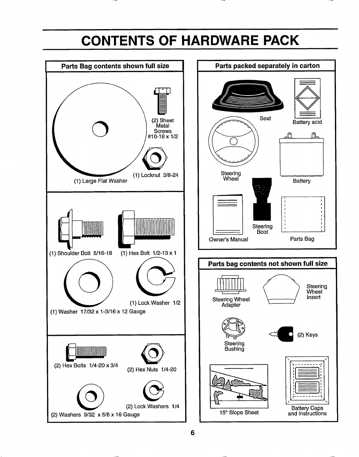
CONTENTS OF HARDWARE PACK
.................................... i ul ii i i iu i ::::::::::::::::::::::::: ......................................
.................................................................... ,i
Parts Bag contents shown full size
Parts packed separately in carton
Q
Metal
(_ (2) Sheet
(1) Locknut 3/8-24
(1) Large Flat Washer
(1) Shoulder Bolt 5/16-t8 (1) Hex Bolt 1/2-13 x 1
Screws
#10-16 x 1/2
Seat
Battery acid
Steering
Wheel Battery
.... I
"----- I
Owner's Manual Parts Bag
ULIIlll Illll I1"
Parts bag contents not shown full size
(1) Lock Washer 1/2
(1) Washer 1"7/32x 1-3/16 x 12 Gauge
(2) Hex Nuts 1/4-20
(2) Lock Washers 1/4
(2) Washers 9/32 x 5/8 x 16 Gauge
Steering
Wheel
Steering Wheel
Adapter
Steering
Bushing
insert
(2) Keys
!
ti '
L'--..... _:H
15° Slope Sheet
!...............
6
Battery Caps
and Instructions
' '' 1
i

ASSEMBLY
_,............... . iUillLiiJl i,,_,-- - ............. ,............. ........ . ..., .............
Your new tractorhas been assembled at the factory withexception ofthose parts left unassembled for shipping purposes,
To ensure safe and proper operationof your tractor all parts and hardware you assemble must be tightened securely. Use
the correct tools as necessary to insureproper tightness.
TOOLS REQUIRED FOR ASSEMBLY
A socket wrench set will make assembly easier. Standard
wrench sizes are listed.
(1) 5/16" wrench
(2) 7/16" wrenches
(1) 1/2" wrench
(1) 3/4" wrench
Tire pressure gauge
Utility knife
(!) 9/t6" wrench
When right or left hand is mentioned in this manual, it
means when you are in the operating position (seated
behind the steedng wheel)°
TO REMOVETRACTOR FROM CARTON
_ LARGE FLAT WASHER
STEERING
WHEEL
ADAPTER--S, TABS
STEERING WHEEL INSERT
!8-.24 LOCKNUT
SHEET
METAL
SCREW
UNPACK CARTON
• Remove all accessible loose parts and parts cartons
from carton (See page 6).
, Cut, from topto bottom, along lineson all four corners
of carton, and lay panels flaL
• Check for any additional loose partsor cartons and
remove_
BEFORE ROLLINGTRACTOR OFF SKID
ATTACH STEERING WHEEL (See Fig. 1)
- Slide the steering bushing over the steering shaft,,
° Raise steering shaft forward until screw holes indash
line up with steering bushing. Install two (2) sheet
metal screws and tighten securely.
° Position steering boot over steering shaft.
° Place tabs of steering boot over tab slots in dash and
push down to secure.
= Slidesteedng wheel adapter onto upper steering shaft.
• Position front wheels of the tractor so they are pointing
straight forward,
, Position steering wheel so cross bars are horizontal
(left to right) andslide onto adapter°
o Assemble large flat washer and 3/8-24 Iocknut and
tighten securely.
° Snap steering wheel insert into center of steering
whee!°
° Remove protective plasticfrom tractorhood and grill.
IMPORTANT:CHECK FOR AND REMOVE ANY STAPLES
IN SKiDTHAT MAY PUNCTURE TIRES WHERE TRACTOR
IS TO ROLL OFF SKIDo
STEERING /_
(ASSEMBLY
POSITION)
SLOT
STEERING SHAFT
(SHIPPING POSITION)
FIG. 1
TO ROLL TRACTOR OFF SKID (See Fig. 6)
• Raise attachment lift lever to its highest position.
° Release parking brake by depressing clutch/brake
pedal.
o Place gearshift lever in neutral (N) position,
• Roll tractor backwards off skid,
• Remove banding holding discharge guard up against
tractor.
7

Jl
HOW TO SET UP ",/'OURTRACTOR
PREPARE BATTERY (See Fig. 2)
....... ,,,,, ,,,,,,,,, ,,,,,,
CAUTION: Wear eye and face shield.
Wash hands or clothing immediately if
& acciden_Uyin contact with battew acid.
Your tractor' has a battery charging system which is
sufficientfor normat use+However, periodicchargingofthe
battery with an automotive charger willextend its life.
• See instructions packed with vent caps in parts bag.
° Fill battery with acid. Fill each cell until it reaches the
bottom of the vent wells. Do not overfill.
• Allow battery to stand and settle for at least thirty
minutes. After standing, check the battery cell acid
level+ If below the vent wells, add more acid until the
correct tevei is reached+
While battery isstanding (after adding acid) and later, while
battery isbeing charged, continue with assembly oftractor+
IMPORTANT: TO MAXIMIZE THE LIFE OF YOUR
BATTERY, IT tS NECESSARY THAT THE BATTERY BE
CHARGED BEFORE USE. FAILURE TO CHARGE
BATTERY CAN RESULT IN A SHORTENED BATTERY
LIFE.
• Charge battery at a rate of 6amperes for1 hour,. Use
a 12 volt battery charger. Observe all safety precau-
tions required for battery charging+
• Check the acid level after the battery is charged. Ifthe
acid has fallen below the correct level,add distilled or
ironfree water+
. Install the vent caps to cover the vent wells+ Wash the
top of the batter] with water to remove any acid, then
wipe dry+
° Check battery case for' leakage to make sure that no
damage has occurred in harldUng+
• Dispose of excess battery acid. Neutralize acid for
disposal by adding it to two gallons of water in a five
gal!on plastic container. Stir with a wooden or plastic
paddle while adding baking soda until the addition of
more soda causes no more foaming,
• Follow instructions on how to install battery.
CUT AWAY VIEW
Do not smoke. Fumes from charged
battery acid are explosive.
Read the instructions included with the
battery vent caps. Always wear gloves,
clothing and goggles to protect your
hands, skin and eyes.
BATTERY
CELL ACID
LEVEL
RG. 2 8
INSTALL SEAT (See Fig. 3)
Adjust seat before tighteningadjustment bolt,
• Remove cardboard packing on seat pan+
• Place seat on seat pan and assemble shoulder boll
o Assemble adjustment bolt, iockwasherand flatwasher
loosely,. Do not tighten+
• Tighten'shoulder bolt securely+
° Lower seat into operating position and sit on seat.
• Slide seat until a comfortable position is reached which
allows you to press clutch/brake pedal all the way
down.
• Get off seat without moving its adjusted position.
• Raise seat and tighten adjustment bolt securely.
SEATPAN
SHOULDER \_\
BOLT
ADJUSTMENT
BOLT
LOCK WASHER
FIG. 3
CHECK TIRE PRESSURE
The tiresonyourtractorwere ovednflated at thefactory for+
shipping purposes. Correct tire pressure is important for
best cutting performance.
• Reduce tire pressure to PSI shown in "PRODUCT
SPECIFICATIONS" on page 3 of this manual.
CHECK DECK LEVELNESS
For best cuttingresults, mower housing should be properly
leveled+ See 'q'O LEVEL MOWER HOUSING" in the
Service and Adjustments section of this manual.
CHECK FOR PROPER POSITION OF ALL
BELTS
See the figures that are shown for replacing motion and
mower blade drive belts in the Service and Adjustments
section of this manual Verify that the belts are routed
correctly
CHECK BRAKE SYSTEM
After you learn how to operate your tractor, check to see
that the brake is properly adjusted. See "TO ADJUST
BRAKE" in the Service and Adjustments section of this
manual.,

ASSEMBLY
INSTALL
BATTERY (See Figs. 4 and 5)
i ii i i ii ii , ::
CAUTION: Do not short battery termi-
nals. Before installing battery, remove
metal bracelets, wristwatch bands,
rings, etc.
Positive terminal must be connected
first to prevent sparking from accident
tat grounding.
• Liftseat to raised position
= Open battery box door°
- Be sure battery drain tube is attached to battery box.,
° Lower battery into battery box with battery terminals
toward front oftractor_
° First connect RED battery cable topositive (+) terminal
with hex bolt, fiat washer, lock washer and hex nut as
shown° Tighten securely.
° Connect BLACK grounding cable to negative (-) termi-
nal with remaining hex bolt, flat washer, lock washer
and hex nut° Tighten securely.
, Close battery box door°
Open battery box door for:
o Inspection for secure connections (to tighten hard-
ware)o
,, Inspection for corrosion.
o Testing battery.
° Jumping (if required).
, Periodic charging.
BATTERY
BOXDOOR
POSITIVE NEGATIVE
(RED) (BLACK)
CABLE CABLE
LOCK
WASHER
FLAT
WASHER
HEX HEX
POSITIVE (+) TERMINAL NEGATIVE (-) TERMINAL
FIG. 4
BATTERY
VENT CAPS
FIG. 5
,/CHECKLIST
BEFORE YOU OPERATE AND ENJOY YOUR NEW
TRACTOR, WE WISH TO ASSURE THAT YOU RECEIVE
THE BEST PERFORMANCE AND SA TISFAC TION FROM
THIS QUALITY PRODUCT.
PLEASE REVIEW THE FOLLOWING CHECKLIST:
,/ All assembly instructions have been completed.
,/ No remaining loose parts in carton,.
,/ Battery is properly prepared and charged. (Minimum
1 hour at 6 amps)o
,/ Seat is adjusted comfortably and tightened securely.
,/ All tires are properly inflated. (For shipping purposes,
the tires were overinflated at the factory).
,/ Be sure mower deck is properly leveled side-to-side/
front-to-rear for best cutting results_ (Tires must be
properly inflated for leveling).
,/ Check mower and drive belts. Be sure they are routed
properly around pulleys and inside all belt keepers.
v" Check wiring. See that all connections are still secure
and wires are properly clamped.
WHILE LEARNING HOWTO USE YOUR TRACTOR, PAY
EXTRA ATTENTION TO THE FOLLOWING IMPORTANT
ITEMS:
J Engine oil is at proper level.
,/ Fuel tank is filled with fresh, clean, regular unleaded
gasoline_
,/ Become famifiar with all controls - their location and
function. Operate them before you start the engine,_
,/ Be sure brake system is in safe operating condition°
9
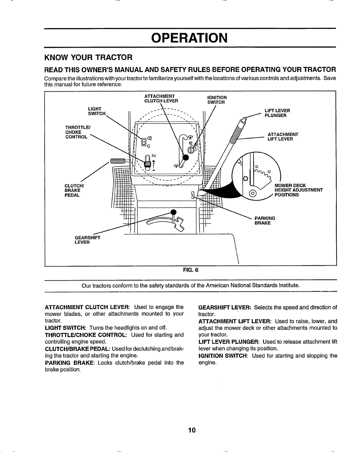
OPERATION
IJ/.HU/'l/''/'l/H''"'''l '"l " ""
KNOW YOUR TRACTOR
READ THIS OWNEWS MANUAL AND SAFETY RULES BEFORE OPERATING YOUR TRACTOR
Compare theillustrationswithyourtractortofamiliarize yourselfwiththelocations ofvariouscontrolsandadjustments, Save
this manual for future reference,,
ATTACHMENT IGNITION
CLUTCH LEVER SWITCH
LIGHT LIFT LEVER
SWITCH PLUNGER
THROTTLE/
CHOKE
CONTROL
ATTACHMENT
LIFT' LEVER
CLUTCW
BRAKE
PEDAL
GEARSHIFT
LEVER
Our tractorsconform to the safety standards of the American National Standards Institute,
ATTACHMENT .CLUTCH LEVER: Used to engage the
mower' blades, or other' attachments mounted to your
tractor_
LIGHT SWITCH: Turns the headlights on and off.
THROTTLE/CHOKE CONTROL: Used for starting and
controlling engine speed.
CLUTCH/BRAKE PEDAL: Used for declutching and brak-
ing the tractor and starting the engine,
PARKING BRAKE: Locks clutch/brake pedal into the
brake position,
MOWER DECK
HEfGHTADJUSTMENT
PARKING
BRAKE
FIG. 6
GEARSHIFT LEVER: Selects the speed and directionof
tractor_
ATTACHMENT LIFT LEVER: Used to raise, lower',and
adjustthe mower deck or other attachments mounted to
yourtractor'.
LIFT LEVER PLUNGER: Used to releaseattachment lift
lever when changing its position,
IGNITION SWITCH: Used for starting and stopping the
engine.
10

OPERATION
_,, i ill _,,.,,_, _ i i nil ...... ............ .i ,,,u,,,lll, i, .
The operation of any tractor can result in foreign objects thrown into the eyes, which
can result in severe eye damage. Always wear safety glasses or eye shields while
operating your tractor or performing any adjustments or repairs. We recommend awide
vision safety mask for over the spectacles or standard safety glasses.
HOW TO USE YOUR TRACTOR
TO SET PARKING BRAKE (See Fig. 7)
= Depress clutch/brake pedal into full "BRAKE" position
and hold,
Place parking brake lever in"ENGAGED" position and
release pressurefrom clutch!brake pedal Pedalshould
remain in"BRAKE" position, Make sure parkingbrake
wilt hold vehicle secure.
ATTACHMENT CLUTCH LEVER
"ENGAGED" POSITION
IGNITION
KEY
CONTROLLEVER PARKING
"BRAKE"
POSITION
CLUTCH/BRAKE PEDAL
"DRIVE"POSITEON
FIG. 7
PARKING BRAKE
"DISENGAGED"POSITION
STOPPING (See Fig. 7)
MOWER BLADES -
• Move attachment clutch lever to "DISENGAGED" po-
sition_
GROUND DRIVE
o Depressclutch/brakepedal intofu{I"BRAKE" position.
° Move gearshift lever to neutral (N) position°
ENGINE -
° Move throttle control to slow (,,=_) position.
NOTE: Failure to move throttle control to slow (-tl)
position and allowing engine to idle before stopping may
cause engine to "backfire".,
° Turn ignition key to "OFF' position and remove key,
Always remove key when leaving tractor to prevent
unauthorized use.
° Never use choke to stop engine,,
"DISENGAGED ='
POSITION
BRAKE
"ENGAGED"
GEAR.
SHIFT
LEVER
NOTE: Under certainconditions when tractor is standing
{dfewiththeengine running, hot engine exhaust gases may
cause "browning" of grass. To eliminate this possibility,
always stop engine when stopping tractor on grass areas.
CAUTION: Always stop tractor corn- I
&
pletely, as described above, before leav- I
ing the operator s position; to empty |
grass catcher, etc. ................ I
TO USE THROTTLE CONTROL (See Fig. 7)
Always operate engineat full throttle.
° Operating engine at less than full throttle reduces the
battery charging rate,,
= Fullthrottleoffersthe best bagging and mower perfor-
mance.
TO MOVE FORWARD AND BACKWARD
(See Fig. 7)
The direction and speed of movement iscontrolledbythe
gearshift tever.
° Start tractor with clutch/brake pedal depressed and
gearshift lever in neutral (N) position,,
= Move gearshift lever to desired position.
= S!owlyrelease clutch/brake pedal tostart movemenL
IMPORTANT; BRING TRACTOR TO A COMPLETE STOP
BEFORE SHIFTING OR CHANGING GEARS. FAILURE
TO DO SO WILL SHORTEN THE USEFUL LIFE OF YOUR
TRANSAXLE,
TO ADJUST MOWER CUTTING HEIGHT
(See Fig. 6)
The posftion of the attachment lift fever determines the
cuttingheight.
• Grasp lift lever,
° Press plunger with thumb and move lever to desired
position_
The cutting height range is approximately t-1/2 to 4",,The
heightsare measured from the ground tothe blade tipwith
the engine not runnfng These heights are approximate
and may vary depending upon soil conditions, height of
grass and types of grass being mowed.
• The average lawn should be cut to approximately 2-1/2
inches during the cool season and to over 3 inches
during hot months. For' healthier and better looking
lawns, mow often and after moderate growth.
° For best cutting performance, grass over 6 inches in
height should be mowed twice,. Make the first cut
relatively high; the second to desired height.
11

OPERATION
TO OPERATE MOWER (See Fig. 8)
Yourtractor is equipped with an operator presence sensing
switch_ Any attempt by the operator to leave the seat with
the engine running and the attachment clutch engaged will
shut off the engine.
= Select desired height of cut.
° Start mower blades by engaging attachment clutch
control.
* TO STOP MOWER BLADES - disengage attachment
clutch control
CAUTION: Do not operate the mower
without either the entire grass catcher,
on mowers so equipped, or the dis-
charge guard in place.
ill
ATTACHMENT CLUTCH LEVER
"DISENGAGED" POSITION
"ENGAGED"
POSITION
ATTACHMENT
LIFT LEVER
HIGH POSITION
TO OPERATE ON HILLS
CAUTION: Do not drive up or down !
hills with slopes greater than 15° and
do not dr!ve across anY slope.
• Choose the slowest speed before starting up or'down
hills°
• Avoid stopping or changing speed on hills.
° If slowing is necessary, move throttle control lever to
slower position°
° If stopping isabsolutely necessary, push clutch/brake
pedal quickly to brake position and engage parking
brake.
• Move gearshift lever to 1st gear. Be sure you have
allowed room for'tractor to roll slightly as you restart
movement.
° To restart movement, slowly release parking brake and
clutch/brake pedal
° Make all turns slowly.
TO TRANSPORT
• Raise attachment lift to highest position with attach-
ment lift control.
• When pushing or towing yourtractor, be sure gearshift
lever is in neutral (N) position.
• Do not push or tow tractor at more than five (5) MPH.
NOTE: To protect hood from damage when transporting
your tractor on a truckora trailer, be sure hood isclosed and
secured totractor. Usean appropriate means oftying hood
to tractor (rope, cord, etc.)..
I
FIG. 8
DISCHARGE
GUARD
BEFORE STARTING THE ENGINE
CHECK ENGINE OIL LEVEL (See Fig. 14)
• The engine inyourtractor has been shipped,from the
factory, already filledwith summer weight oil.
• Check engine oil with tractor on level ground.
• Remove oil fitlcap/dipstick and wipe clean, reinsert the
dipstick and screw cap tight, wait for' a few seconds,
remove and read oil level, if necessary, add oil until
"FULL" mark on dipstick is reached.. Do not overfill.
• For cold weather operation you should change oil for
easier starting (See "OIL VISCOSITY CHART" in the
Customer Responsibilities section of this manual).
• To change engine oil, see the Customer Responsibili-
ties section in this manual.
12

OPEBATIO
ADD GASOLINE
= Fill fuel tank. Use fresh, clean, regular unleaded
gasoline+ (Use of leaded gasoline will increase carbon
and lead oxide deposits and reduce valve life)..
IMPORTANT: WHEN OPERATING IN TEMPERATURES
BELOW 32'_F(0°C), USE FRESH, CLEAN WINTER GRADE
GASOLINE TO HELP INSURE GOOD COLD WEATHER
STARTING.
WARNING: Experience indicates that alcohol blended
fuels (called gasohol or using ethanol or methanol) can
attract moisture which leads to separation and formation of
acids during storage,. Acidic gas can damage the fuel
system of an engine while in storage. To avoid engine
problems, the fuel system should be emptied before stor-
age of 30 days or longer. Drain the gas tank, start the
engine and let it run until the fuel lines and carburetor are
empty. Use fresh fuel next season,. See Storage Instruc-
tions for additional information,. Never use engine or
carburetor cleaner products in the fuel tank or permanent
damage may occur.
......................... i i
filler neck. Do not overfill. Wipe offany
I_ CAUTION: Fill to bottom of gas tank
spilled oil or fuel. Do not store, spill or
use gasoline near an open flame.
I III iiiiiiiiii iiiiiii
TO START ENGINE (See Fig. 7)
When starting engine for the first time or if engine has run
out of fuel, itwill take extra cranking time to move fuel from
the tank to the engine.
= Depress clutch/brake pedal and set parking brake.
= Place gearshift lever in neutral (N) position.,
° Move attachment clutch to "DISENGAGED" position..
o Move throttle control lever to choke (N) position for
cold engine start. Forwarm engine start, move throttle
control to fast (,_) position.
= Insert keyinto ignit+onandturnkey clockwise to"START"
position and release key as soon as engine starts+ Do
not run starter continuously for more than fifteen
seconds per minute. If engine does not start after
several attempts, move throttle control to fast (,_)
position, wait a few minutes and try again.
° When engine starts, move throttle control to desired
position.
° Allow engine to warm up for a few minutes before
engaging drive or attachments+
NOTE: If at a high altitude (above 3000 feet) or in cold
temperatures (below 32°F), the carburetor fuel mixture
may need to be adjusted for best engineperformance. See
"TO ADJUST CARBURETOR" inthe Service and Adjust-
ments section of this manual+
MOWING TiPS
° Tirechainscannot be used when the mower housing is
attached to tractor,
° Mower should be properly leveied for best mowing
performance,, See "TO LEVEL MOWER HOUSING" in
the Service and Adjustments section of this manual
° The left hand side of mower should be used for trim-
mingo
,; Drive so that clippings are discharged onto the area
thathas been cut. Have the cut area to the right of the
machine+ This witl result in a more even distribution of
clippings and more uniform cutting,.
= When mowing]large areas, start by turning to the right
so that clippings wilt discharge away from shrubs,
fences, driveways, etc,, After one ortwo rounds, mow
in the opposite direction making left hand turns until
finished(See Fig.. 9 ).
• If grass is extremely tall, it should be mowed twice to
reduce load and possible fire hazard from dried clip-
pings.+Make firstcut relatively high; the second to the
desired height.
- Do not mow grass when it is wet+ Wet grass will plug
mower and leave undesirable clumps_ Allow grass to
dry before mowing.
° Always operate engine at full throttle when mowing to
assure better mowing performance and proper dis-
charge of material. Regulate ground speed by select-
ing a low enough gear to give the mower cutting
performance as well as the quality of cut desired.
• When operating attachments, select a ground speed
that will suit the terrain and give best performance of
the attachment being used.
FIG. 9
13
CUSTOMER RESPONSIBILITIES
.................. ,,,,,,,,,,,, ,,,,,,,, ,, ,,,,, ,,, ,,,,
Check Brake Operation V' If #
Check Tire Pressure If V #'
T Check for Loose Fasteners tf t_7 If
a Lubricati0nSharpen)ReP'iace"M"°werBiadeSchart _V_64 if " _
C Check Battery l:e_(el/Recharge ................. , , .... =_
0 Clean Battery and Termlnals if V'
R CheckTransaxleCooling ' '_ ......... 1 " I 1 " I i
AdjUst Blade Belt(s) Tension VP5
Adjust 'Motion Drive Belt(s) Tension j .... I/s
Check Engine 011Level If If
C,eanAirF,ter ¢_I 1 l ....
..................._ ! !............._I I I..............I I I I I
G Inspect MufflerlSpark Arrester = .............. If
I Replace Oil Filter (if equipped) ..... V_1,2 ..........
N . ........................... j
Replace Spark Plug
Replace Air Filter Paper Cartridge VP2
Replace Fuel Filter
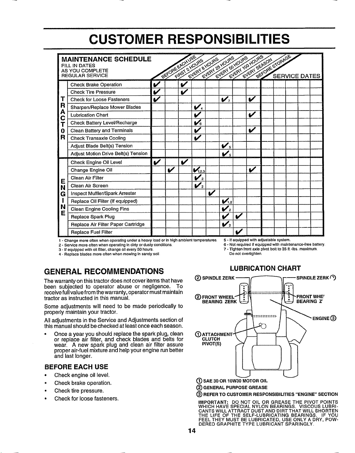
1 - Change more often when operating under a heavy load or in high ambient temperatures,
2 - Service more often when operating in dirty or dusty conditions.
3 - If equipped wtlh oil filter, change oil eve_ 50 hours,
4 - Replace blades more often when mowlng In sandy solt
. I 1 ! t ......1_............... , IClean Engine Coohng Fins 2 j '
5 - If equipped wllh adjustable system,.
6 - Not required If equipped with maintenance-tree battery
7 - Tighten front axle pivot bolt to 35 it -Ibs,. maximum_
Do not ove_tighten.
GENERAL RECOMMENDATIONS
The warrantyon this tractor does not cover items that have
been subjected to operator abuse or negligence. To
receive full value from the warranty, operator must maintain
tractor as instructed in this manual.
Some adjustments will need to be made periodically to
properly maintain your tractor.
All adjustments in the Service and Adjustments section of
this manual should be checked at least once each season°
• Once a year you shoutd replace the spark ptug, clean
or replace air filter, and check blades and belts for
wear. A new spark plug and clean air filter assure
proper air-fuel mixture and help your engine run better
and last longer..
BEFORE EACH USE
• Check engine oil level.
= Checkbrake operation.
. Checktire pressure.
• Check for loose fasteners.
LUBRICATION CHART
(_) SPINDLE ZERK
(_ 'WHE r
BEARING ZERK BEARING Z'
@
CLUTCH
PIVOT(S)
(_ SAE 30 OR 10W30
(_ GENERAL PURPOSE GREASE
_) REFER TO CUSTOMER RESPONSIBILITIES "ENGINE"
IMPORTANT: DO NOT OIL OR GREASE THE PIVOT POINTS
WHICH HAVE SPECIAL NYLON BEARINGS, VISCOUS LUBRI-
CANTS WILL ATTRACT DUST AND DIRT THAT WILL SHORTEN
THE LIFE OF THE SELF-LUBRICATING BEARINGS. IF YOU
FEEL THEY MUST BE LUBRICATED, USE ONLY A DRY, POW-
DERED GRAPHITE TYPE LUBRICANT SPARINGLY,_
MOTOR OIL
14
ZERK(_
®
SECTION
CUSTOM ESPONSmBILmTIES
TRACTOR
Always observe safety rules when performing any mainte-
nance,
BRAKE OPERATION
Jftractor requires more than six _6)feet stopping distance
at high speed inhighest gear, then brake must be adjusted..
(See 'q'O ADJUST BRAKE" in the Service and Adjust-
ments section of this manual)
TIRES
. Maintain proper air pressure in all tires (See "PROD-
UCT SPECIFICATIONS" on page 3 of this manual).
° Keep tires free of gasoline, oil, or insectcontrol chemi-
cals which can harm rubber°
o
Avoid stumps, stones, deep ruts, sharp objects and
other hazards that may cause tire damage_
BLADE CARE
For best results mower blades must be kept sharp_ Re-
place bent or damaged blades.
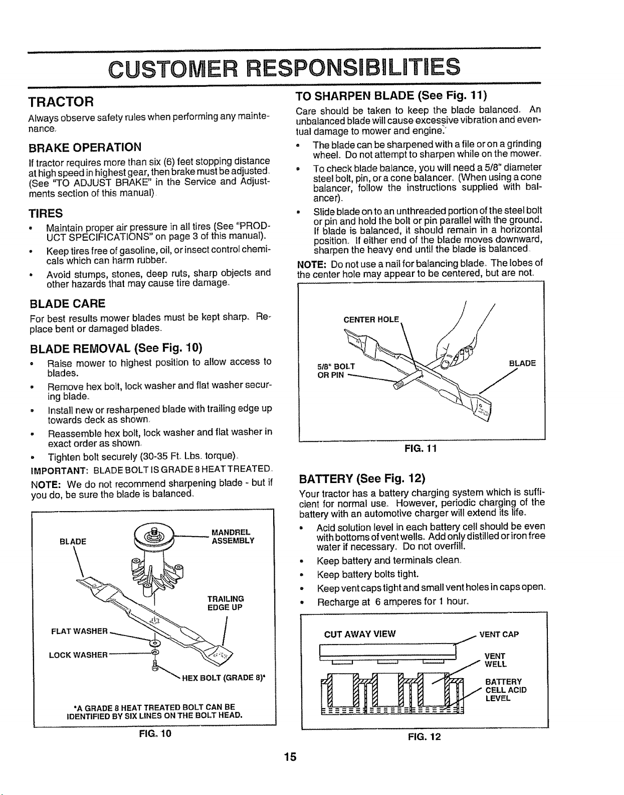
BLADE REMOVAL (See Fig. 10)
• Raise mower to highest position to allow access to
blades_
° Remove hex bolt, lock washer and flat washer secur-
ing blade.
. _nstallnew or resharpened blade with trailing edge up
towards deck as shown.
°
Reassemble hex bolt, lock washer and flat washer in
exact order as shown.
° Tighten bolt securely (30-35 FL Lbs..torque),
IMPORTANT: BLADE BOLTtSGRADE BHEATTREATED,
NOTE: We do not recommend sharpening blade - but if
you do, be sure the blade is balanced.
BLADE
MANDREL
ASSEMBLY
\
TRAILING
EDGE UP
TO SHARPEN BLADE (See Fig. 11)
Care should be taken to keep the blade balanced. An
unbalanced blade wil!cause excessive vibration and even-
tual damage to mower and engine.*
• The blade can be sharpened with a file or on a grinding
wheel° Do not attempt to sharpen while on the mower°
• To check blade bafance, you will need a 5/8" diameter
steel bolt, pin, or acone balancer,. (When using a cone
bafancer, follow the instructions supplied with bal-
anGer),,
° Slide blade on to an unthreaded portion of the steel bolt
or pin and hold the bolt or pin parallel with the ground.
If blade is balanced, it should remain in a horizontal
position.. If either end of the blade moves downward,
sharpen the heavy end until the blade is balanced
NOTE: Do not use anail for balancing blade. The lobes of
the center hole may appear to be centered, but are not..
CENTER HOLE / /
OR PiN __
FIG. 11
BATTERY (See Fig. 12)
Your tractorhas a battery charging system which is suffi-
cient for normal user However, periodic charging of the
battery with an automotive charger will extend its life.
. Acid solution level in each battery ceil should be even
with bottoms of vent wells. Add only distil led or iron free
water if necessary_ [30 not overfill.
° Keep battery and terminals clean..
• Keep battery bolts tight.
. Keep vent caps tight and small vent holes in caps open.
° Recharge at 6 amperes for I hour°
FLAT WASI"
LOCK WASHER'
" HEX BOLT (GRADE 8)*
"A GRADE 8 HEAT TREATED BOLT CAN BE
IDENTIFIED BY SIX LINES ON THE BOLT HEAD.
FIG. 10
CUT AWAY VIEW / VENT CAP
!'* .......................... _ VENT
L-..--.J _ _ WELL
BATTERY
CELL ACID
LEVEL
FIG, 12
15

Hi H IHH I
CUSTOMER R SIBILITIES
TO CLEAN BATTERY AND TERMINALS
Corrosion and dirt on the battery and terminals can cause
the battery to "leak" power,.
• Open battery box door.
• Disconnect BLACK battery cable first then RED bat-
tory cable and remove battery from tractor_,
° Wash battery with solution of four tablespoons of
baking sodato one gallon ofwater,, Becareful not to get
the soda solution into the cells,_
• Rinse the battery with plain water and dry.
• Clean terminalsand batterycable endswithwire brush
untilbright.
• Coat terminals with grease or petroleumjelly°
• Reinstall battery (See "INSTALL BATTERY" in the
Assembly section ofthis manual).,
V-BELTS
Check V-beltsfor deteriorationand wear after 100 hours of
operation and replace if necessary,, The belts are not
adjustable°Replace belts ifthey begin toslip from wear.
TRANSAXLE COOLING
Keep transaxle free from build-up of dirt and chaff which
can restrict cooling.
ENGINE
• Catch oil in a suitable container,
° Remove oil fill cap/dipstick. Be careful not to allow dirt
to enter' the engine when changing oil.
• Remove drain plug.
- After oil has drained completely, replace oil drain plug
and tighten securely_
• Refill engine with oil through oil fill dipstick tube. Pour
slowly. Do not overfill,. For approximate capacity see
"PRODUCT SPECIFICATIONS" on page 3 of this
manual.
• Use gauge on oil fill cap/dipstick for checking level Be
sure dipstick cap is tightened securely for accurate
reading_ Keep oil at "FULL" iine on dipstick,
OIL FILL
CAP,'DIPSTICK
OIL DRAIN PLUG
FIG. 14
LUBRICATION
Only use high quality detergent oil rated with API service
classificationSForSG. Select theoit'sSAEviscositygrade
accordingto your expected operating temperature_
SAE VISCOSR-Y GRADES
mz
4
=F -20"
TEMPERATURE RANGE ANTIcIPATEO BEFORE. NEXT OIL CHANGE,
NOTE: Although multi-viscosity oils (5W30, 10W30 etc.)
improve startingin coldweather, these multi-viscosity oils
will resultin increased oil consumptionwhen used above
32°F. Check your engine oillevel morefrequently to avoid
possibleengine damage from runninglow on oil.
Change the oit after the first two hours of operation and
every 25 hours thereafter'or at least once a year if the
tractoris not used for 25 hours in one year.
Check the crankcase oil level before starting the engine
and after each eight (8) hours ofoperation. Tighten oil fill
cap/dipsticksecurety each time you check the oil level.
TO CHANGE ENGINE OIL (See Figs. 13 and 14)
Determine temperature rangeexpected before oilchange.
All oil must meet API service classificationSF or SG.
° Be sure tractor' is on level surface.
• Oil willdrain more freely when warm.
0= 30" 32° '40° 60° 80' 100_'
FIG. 13
L
AIR FILTER (See Fig. 15)
Your engine will not run properly using a dirty air filter.
Clean the foam pro-cleaner after every 25 hours of opera-
tion or every season. Service paper'cartridge every 100
hours ofoperationorevery season,whichever occursfirst..
Service air cleaner more often under dusty conditions.
• Remove knob(s) and cover.
TO SERVICE PRE-CLEANER
• Slide foam pro-cleaner off cartridge°
° Wash it in liquid detergent and water.
• Squeeze it dry in a clean cloth.
• Saturate it in engine oil. Wrap it in clean, absorbent
clothand squeeze to remove excess clio
° If very dirty or damaged, replace pre-cleaner,
• Reinstallpro-cleaner over cartridge.
° Reinstall cover and secure with knob(s)o
TO SERVICE CARTRIDGE
° Remove cartridgenut.
° Carefully remove cartridgeto prevent debrisfrom en-
tedng carburetor'. Clean base carefully to prevent
debris from enteringcarburetor.
• Clean cartridgebytapping gentlyonflat surface. Ifvery
dirtyor damaged, replace cartridge,
• Reinstallcartridge, nut, precleaner, cover and secure
with knob(s)_
IMPORTANT: PETROLEUM SOLVENTS, SUCH AS
KEROSENE, ARE NOT TO BE USED TO CLEAN THE
CARTRIDGE,, THEY MAY CAUSE DETERIORATION OF
THE CARTRIDGE DO NOT OIL CARTRIDGE, DO NOT
USE PRESSURIZED AIR TO CLEAN OR DRY
CARTRtDGE_
16

CUSTOMER
KNOB
RESPO
FIG, 15
CLEAN AIR SCREEN (See Fig. 16)
Air screen must be kept free of dirt and chaff to prevent
engine damage fromoverheating° Clean witha wire brush
or compressed air to remove dirt and stubborn dried gum
fibers..
ENGINE COOLING FINS (See Fig. 16)
Remove any dust, dirt or oil from engine cooling fins to
prevent engine damage from overheating.
- Remove screws from blower housing and lift housing
and oil fill tube assembly off engine.
= Cover oil fill opening to prevent entry of dirt.
o Remove the screws securing the starter housing and
lift housing off engine°
= Use compressed air or stiff bristle brush to thoroughly
clean engine cooling fins,
e
To reassemb{e, reverse above procedure,
SCREWS
OIL FILL
TUBE
ASSEMBLY
BLOWER HOUSING
SCREWS
AIR SCREEN
MUFFLER
Inspect and repiace corroded muffler and spark arrester (if
equipped) as it could create a fire hazard and/or damage..
SPARK PLUGS
Replace spark plugs at the beginning of each mowing
season or after every t00 hours of operation, whichever
occurs first. Spark plug type and gap setting are shown in
"PRODUCT SPECIFICATIONS" on page 3 of this manual
IN-LINE FUEL FILTER (See Fig. 17)
The fuel filter should bereplaced onceeach season. Iffuel
filter becomes clogged,obstructingfuel flow tocarburetor,
replacement is required.
• With engine coot, remove filter and plug fuel line
sections°
Place new fuelfilter in position in fuel line with arrow
pointing towards carburetor.
Be sure there are no fuel line leaks and clamps are
properly positioned.
Immediately wipe up any spilled gasoiineo
CLAMP.
_____ CLAMP
FUEL _ // /_-_---_
FILTER -- "_=_L.._.__/
FIG. 17
CLEANING
° Clean engine, battery, seat, finish, etco of all foreign
matter.
• Keep finished surfaces and wheels free of all gasoline,
oil, etco
° Protect painted surfaces with automotive type wax.
We do not recommend using a garden hose to clean your
tractor unless the electrical system, muffler, air filter and
carburetor are covered to keep water out, Water in engine
can result in a shortened engine life.
ENGINE COOLING FINS
SPARK
PLUG
FIGo16
'17
 Loading...