

Page 1

®
EL
÷Assembly
Operation
Customer Responsibilities
÷Service and Adjustments
®Repair Parts
917.257560 OWNER'SMANUAL
Converti bile
CAUTION: Read and follow all safety rules and instructions before operating this equipment.
Page 2
Safe Operation Practices for Ride-On Mowers
iMPORTANT: THIS CUTTING MACHINE IS CAPABLE OF AMPUTATING HANDS AND FEETAND THROWING OBJECTS.
FAILURE TO OBSERVE THE FOLLOWING SAFETY INSTRUCTIONS COULD RESULT iN SERIOUS INJURY OR DEATH.
GENERAL OPERATIONL
, Read, understand, and follow all instructions in the manual
and on the machine before starting.
* Only allow responsible adults, who are familiar with the
instructions, to operate the machine.
o Clear the area of objects such as rocks, toys, wire, etc.,
which could be picked up and thrown by the blade.
o Be surethe area isclear of other people before mowing. Stop
machine if anyone enters the area.
, Never carry passengers.
Do not mow in reverse unless absolutely necessary. Always
look down and behind before and while backing.
* Be aware of the mower discharge direction and do not point
it at anyone. Do not operate the mower without either the
entire grass catcher or the guard in place.
- Slow down before turning.
Never leave a running machine unattended. Always turn off
blades, set parking brake, stop engine, and remove keys
before dismounting.
o Turn off blades when not mowing.
Stop engine before removing grass catcher or unclogging
chute.
, Mow only in daylight or good artificial light.
,, Do not operate the machine while under the influence of
alcohol or drugs.
Watch for traffic when operating near or crossing roadways.
. Use extra care when loading or unloading the machine into
a trailer or truck.
mi. SLOPE OPERATION
Slopes are a major factor related to loss-of-control and tipover
accidents, which can result in severe injury or death. All slopes
require extra caution, if you cannot back up the slope or ifyou feel
uneasy on it, do not mow it.
DO:
o
Mow up and down slopes, not across.
o Remove obstacles such as rocks, tree limbs, etc.
o Watch for holes, ruts, or bumps. Uneven terrain could
overturn the machine. Taft grass can hide obstacles.
- Use slow speed. Choose a low gear so that you will not have
to stop or shift while on the slope.
• Follow the manufacturer's recommendations for wheel
weights or counterweights to improve stability.
o Use extra care with grass catchers or other attachments.
These can change the stability of the machine.
® Keep all movement on the slopes slowand gradual. Do not
make sudden changes in speed or direction.
o Avoid starting or stopping on a slope. If tires lose traction,
disengage the blades and proceed slowly straight down the
slope.
DO NOT:
• Donotturnonslopesunlessnecessary, andthen, turnslowly
and gradually downhill, if possible.
Do not mow near drop-offs, ditches, or embankments. The
mower could suddenly turn over ifa wheel is over the edge
of a cliff or ditch, or if an edge caves in_
Do not mow on wet grass. Reduced traction could cause
sliding.
o Do not try to stabilize the machine by putting your foot on the
ground.
, Do not use grass catcher on steep slopes.
iii. CHILDREN
Tragic accidents can occur if the operator is not alert to the
presence of children. Children are often attracted to the machine
and the mowing activity. Never assume that children will remain
where you last saw them.
o
Keep children out of the mowing area and under the watchful
care of another responsible adult.
e
Be alert and turn machine off if children enter the area.
o
Before and when backing, look behind and down for small
children.
®
Never carry children. They may fall off and be seriously
injured or interfere with safe machine operation.
®
Never allow children to operate the machine.
o
Use extra care when approaching blind corners, shrubs,
trees, or other objects that may obscure vision.
iV.
SERVICE
e
Use extra care in handling gasoline and other fuels. They are
flammable and vapors are explosive.
Use only an approved container.
Never remove gas cap or add fuel with the engine
running. Allow engine to cool before refueling. Do not
smoke.
Never refuel the machine indoors.
Never store the machine or fuel container inside where
there is an open flame, such as a water heater.
,, Never run a machine inside a closed area.
Keep nuts and bolts, especially blade attachment bolts, tight
and keep equipment in good condition.
Never tamper with safety devices. Check their proper
operation regularly.
® Keep machine free of grass, leaves, or other debris build-up.
Clean oil or fuel spillage. Allow machine to cool before
storing.
o Stop and inspect the equipment if you strike an object.
Repair, if necessary, before restarting.
,, Never make adjustments or repairs with the engine running.
,, Grass catcher components are subject to wear, damage, and
deterioration, which could expose moving parts or allow
objects to be thrown. Frequently check components and
replace with manufacturer's recommended parts, when nec-
essary.
® Mower blades are sharp and can cut. Wrap the blade(s) or
wear gloves, and use extra caution when servicing them.
o Check brake operation frequently. Adjust and service as
required.
Look for this symbol to point out impor-
tant safety precautions, it means
CAUTION!!! BECOME ALERT!!! YOUR
SAFETY !S iNVOLVED.
CAUTION: Always disconnect spark
plug wire and place wire where it cannot
contact spark plug in order to prevent
accidental starting when setting up,
transporting, adjusting or making
repairs,
2
Page 3

CONGRATULATIONS on your purchase of a Sears
Tractor. it has been designed, engineered and manufac _
tured to give you the best possible dependability and
performance.
Should you experience any problem you cannot easily
remedy, p!ease contact your nearest Sears Authorized
Service Center/Department. We have competent, weIF
trained technicians and the proper tools to service or repair
this unit.
Piease read and retain this manual. The instructions will
enable you to assemble and maintain your unit properly.
Always observe the "SAFETY RULES".
MODEL
NUMBER 917.257560
SERIAL
NUMBER
DATE OF PURCHASE
THE MODEL AND SERIAL NUMBERS WILL BE FOUND
ON A PLATE UNDER THE SEAT
YOU SHOULD RECORD BOTH SERIAL NUMBER AND
DATE OF PURCHASE AND KEEP IN A SAFE PLACE
FOR FUTURE REFERENCE.
HORSEPOWER: 18.0
GASOLINE CAPACITY 3.5 GALLONS
AND TYPE: UNLEADED REGULAR
OIL TYPE (APFSG): SAE 30 (above 32°F)
SAE 5W_30 (below 32°F)
OIL CAPACITY: W/O FILTER: 3.0 PINTS
SPARK PLUG: CHAMPION RJq9LM
(GAP: .030") STD361458
VALVE CLEARANCE: INTAKE: .004" - .006"
EXHAUST: .007" - .009"
GROUND SPEED (MPH): FORWARD:
1st 0.77
2nd 1.46
3rd 3.4!
4th 4.34
5th 5°57
REVERSE: I °07
TIRE PRESSURE: FRONT: 14PSI
REAR: 10 PSI
_HARGING SYSTEM: 5 AMPS BATTERY
3 AMPS HEADLIGHTS
BLADE BOLT TORQUE: 30-35 FT. LBS.
MAINTENANCE AGREEMENT
A a.... '4o_,,_,_o,_,',_ ,,Agreement is _v_il_hl_ nn this prod°
uct. Contact your nearest Sears store for details.
CUSTOMER RESPONSJBJLJTNES
Read and observe the safety rules.
Follow a regular schedule in maintaining, caring for and using
your unit.
o Fol!ow the instructions under "Customer Responsibilities"
and "Storage" sections of this owner's manual.
WARNING: This unit is equipped with an internal combus o
tion engine and should not be used on or near any unim o
proved forest-covered, brush-covered or grass-covered
land unless the engine's exhaust system is equipped with
a spark arrester meeting applicable local or state laws (if
any), If a spark attester is used, it should be maintained in
effective working order by the operator.
Jn the state of California the above is required by law
(Section 4442 of the California Public Resources Code).
Other states may have similar iaws Federal laws apply on
federal lands. A spark arrester fo _:_ muffler is available
through your nearest Sears Autho zed Service Center/
Department (See REPAIR PARTS section of this manual).
LIMITED TWO YEAR WARRANTY ON ELECTRIC START RIDING EQUIPMENT
For two (2) years from the date of purchase, if this riding equipment is maintained, lubricated and tuned up according to the
instructions in the owner's manual, Sears will repair or replace, free of charge, any parts found to be defective in material or
workmanship.
This Warranty does not cover:
Expendable items which become worn during normal use, such as blades, spark plugs, air cleaners and belts..
o Tire replacement or repair caused by punctures from outside objects, such as nails, thorns, stumps, or glass.
o Repairs necessary because of operator abuse, negligence, improper storage or accident or the failure to maintain the
equipment according to the instructions contained in the owner's manual
Riding equipment used for commercial or rental purposes
LiMiTED 90 DAY WARRANTY ON BATTERY
For ninety (g0) days from date of purchase, if any battery included with this riding equipment proves defective in material or
,._zorkmanshipand our testing determines the batte,,wwilt not hold a charge, Sears will replace the battery at no charge.
WARRANTY SERVICE IS AVAILABLE BY RETURNING THE RIDING EQUIPMENT TO THE NEAREST SEARS SERVICE
CENTER!DEPARTMENT _NTHE UNITED STATES.
This Warranty gives you specific legal rights, and you may also have other rights which may vary from state to state.
SEARS, ROEBUCK AND CO., D/817 WA, HOFFMAN ESTATES, ILLINOIS 60179
3
Page 4
TABLE OF
CONTENTS
SAFETY RULES ............................................................ 2
PRODUCT SPECiFiCATiONS ....................................... 3
CUSTOMER RESPONSIBmLITIES ..................... 3, 15=18
WARRANTY ................................................................... 3
TRACTOR ACCESSORIES ........................................... 5
ASSEMBLY .............................................................. 7-10
OPERATION ........................................................... 11-14
iNDEX
A
Accessories ........................................... 5
Adjustments:
Brake ............................................ 21
Carburetor .................................... 24
Mower
FrontoTo=Back ......................... 20
Side-To-Side ........................... 20
Throttle Control Cable .................. 23
Air Filter, Engine ............................. 17-18
Air Screen, Engine ............................... 18
Assembly .......................................... 7-10
B
Battery:
Charging ......................................... 8
Cleaning ....................................... 17
Levels ........................................8,16
Preparation ..................................... 8
Starting with Weak Battery ........... 22
Storage .........................................25
Terminals......................................17
Belt:
Motion Drive
Removal/Replacement ............ 21
Mower Blade(s)
Removal/Replacement ............ 21
Blade:
Sharpening ...................................16
Replacement ................................ 16
Brake Adjustment ................................ 21
C
Carburetor Adjustment ........................ 24
Controls, Tractor .................................. 11
Customer Responsibilities .............. 15ol 8
Engine:
Air Filter ............................... 17-18
Air Screen, Engine ................... 18
Cooling Fins, Engine ................ 18
EngineOil.................................17
FuelFilter.................................18
Spark Plug(s)............................18
Tractor:
Battery......................................17
Blade ........................................16
Lubrication Chad ...................... 15
Maintenance Schedule ............. 15
Tire Care ..........................8,16,22
Transaxle ..................................17
Cutting Height, Mower ......................... 12
Electrical
Interlocks and Relays ................... 23
Schematic ..................................... 29
Wiring Diagram ............................. 30
Engine:
Air Filter ........................................18
AirScreen.....................................18
CoolingFins,Engine ....................18
OilChange ...................................17
OilLevel..................................13,17
OilType ........................................17
Preparation ................................... 13
Repair Parts ............................ 30-47
Starting ......................................... 14
Storage ......................................... 25
F Ill.Ill,
Air Filter ................................... 17-18
Fuel ......................................... 17-18
Fuel:
Type ............................................. 13
Storage ......................................... 25
Fuse ..................................................... 23
Hood Removal/Installation ................... 23
LevelingMower Deck ..........................20
Lubdcation:
Chart.............................................15
Maintenance Schedule ........................ 15
Mower:
Adjustment, Front-to-Back ............ 20
Adjustment, Side-to-Side .............. 20
Blade Sharpening ......................... 16
Blade Replacement ...................... 16
Cutting Height ............................... 12
Installation .................................... 19
Operation ......................................13
Removal .......................................19
Mowing Tips ........................................ 14
Muffler .................................................t8
OiL
Cold Weather Conditions ,;...... 13,17
Engine ..................................... !3,17
Storage.........................................25
MAINTENANCE SCHEDULE ...................................... 15
SERVmCE AND ADJUSTMENTS ............................ 19-24
STORAGE .................................................................... 25
TROUBLESHOOTmNG ............................................ 26-2?
REPAIR PARTS oTRACTOR ................................. 30-4?
REPAIR PARTS - ENGINE ..................................... 48=53
PARTS ORDERING/SERVICE ................ BACK COVER
E
Operation ........................................ 11-14
Operating Mower ................................. 13
Options:
Accessories....................................5
Spark Attester ........................... 3,40
P
Parking Brake ...................................... 12
Pads Bag ............................................... 6
Pads, Replacement/Repair ............ 30-47
Product Specifications ........................... 3
R
Repair Pads ................................... 30-47
F
Safety Ruies .......................................... 2
Seat ....................................................... 8
Service and Adjustments ................ 19-24
Carburetor .................................... 24
Fuse ............................................. 23
Hood Removal!Installation ........... 23
Motion Drive Belt
H
L
Slope Guide Sheet .............................. 55
M
Spark Plug(s) ....................................... 18
Specifications ........................................ 3
Starting the Engine ......................... 13-14
Steering Wheet ................................. 7,22
Stopping the Tractor ............................ 12
Storage ................................................25
Removal/Replacement ............ 21
Mower Belt(s)
RemovaVReplacement ............ 21
Mower Adjustment
Front-to-Back ........................... 20
Side-to-Side ............................. 20
Mower Removal ........................... 19
Tire Care ............................... 8,16,22
S
T
Throttle Control Cable Adjustment ...... 23
Tires ............................................. 8,16,22
Trouble Shooting Chart .................. 26-27
Transaxle .............................................17
........................... _%U
0
Warranty ................................................3
Wiring Diagram .....................................29
WiringSchematic.................................30
W
4
Page 5
ESSO
These accessories and attachments were available through most Sears retaii outlets and sewice canters when the tractor was purchased.
Most Sears stores can order these items for you when you provide the model number of your tractoL
AN
TS
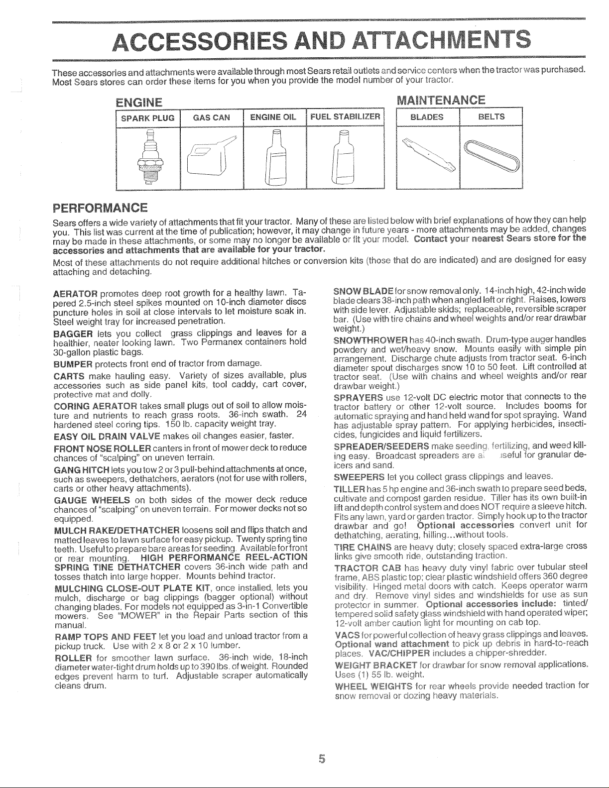
ENGINE MAINTENANCE
SPARK PLUG GAS CAN BLADES l BELTS
ENGINE OiL FUEL STABILIZER
PERFORMANCE
Sears offers a wide variety of attachments that fit your tractor. Many of these are listed below with brief explanations of how they can help
you. This list was current at the time of puMication; however, it may change in future years - more attachments may be added, changes
may be made in these attachments, or some may no longer be available or fit your model. Contact your nearest Sears store for the
accessories and attachments that are avaitabMe for your tractor.
Most of these attachments do not require additional hitches or conversion kits (those that do are indicated) and are designed for easy
attaching and detaching.
AERATOR promotes deep root growth for a healthy lawn. Ta-
pered 2.5cinch steel spikes mounted on 10-inch diameter discs
puncture holes in soil at close intervals to let moisture soak in.
Steel weight tray for increased penetration°
BAGGER tets you collect grass clippings and leaves for a
H_a_,,e_, neater _,Jo^,aM , w_,
30-gallon plastic bags.
BUMPER protects front end of tractor from damage.
CARTS make hauling easy. Variety of sizes available, plus
accessories such as side panel kits, tool caddy, cart cover,
protective mat and do_ly.
CORING AERATOR takes small plugs out of soil to atlow mois-
ture and nutrients to reach grass roots. 36-inch swath. 24
hardened steel coring tips. 150 lb. capacity weight tray.
EASY OtL [::}RAIN VALVE makes oil changes easier, faster.
FRONT NOSE ROLLER canters infront of mower deck to reduce
chances of "sca_ping" on uneven terrain.
GANG HITCH lets you tow 2or 3 puibbehind attachments at once,
such as sweepers, dethatchers, aerators (not for use with rollers,
carts or other heavy attachments).
GAUGE WHEELS on beth sides of the mower deck reduce
chances of "scalping" on uneven terrain. For mower decks not so
equipped.
MULCH RAKFJDETHATCHER loosens soil and flips thatch and
matted leaves to tawn sudace for easy pickup. Twenty spring tine
teeth. Useful to prepare bare areas for seeding Available for front
or rear mounting. NIGH PERFORMANCE REEL_ACTION
SPR_NG T_NE DETHATCHER covers 36-inch wide path and
tosses thatch into large hopper° Mounts behind tractor.
MULCHING CLOSEoOUT PLATE K1T, once installed, lets you
mulch, discharge or bag clippings (bagger optional) without
changing blades, For models not equipped as 3oim1 Convertible
mowers See "MOWER" in the Repair Parts section of this
manua_
RAMP TOPS AND FEET _etyou load and unload tractor from a
pickup truck° Use with 2 x 8 or2 x 10 iumben
ROLLER for smoother _awn sudace. 36cinch wide, 18cinch
diameterwater-tigbt drum holds up to 390 Ibs of weight. Rounded
edges prevent harm to tud. Adjustable scraper automatically
cleans drum_
SNOW BLADE for snow removal only. 14qnch high, 42qnch wide
blade clears 38°inch path when angled left or righL Raises, lowers
with side _ever. Adjustable skids; replaceable, reversible scraper
bar. (Use with tire chains and wheel weights and/or rear drawbar
weight.)
SNO'._a!THROWER has 40-inch swath. Drum-type auger handles
powdery and wet/heavy snow. Mounts easily with simple pin
arrangement, Discharge chute adjusts from tractor seat. 6qnch
diameter spout discharges snow !0 to 50 feel Lift controlled at
tractor seat, (Use with chains and whee_ weights and/or rear
SPRAYERS use 12-volt DC electric motor that connects to the
tractor battery or other 12ovolt source. Inctudes booms for
automatic spraying and hand hetd wand for spot spraying. Wand
has adjustable spray pattem. For applying herbicides, insectio
cides, fungicides and liquid fertilizerso
SPREADERJSEEDERS make seedinq fe ti]izing, and weed killo
ing easy. Broadcast spreaders are a seful for granular de-
icers and sand.
SWEEPERS let you collect grass clippings and leaves.
T_LLER has 5 hp engine and 36°inch swath to prepare seed beds,
cultivate and compost garden residue. Tiller has its own builtqn
tiftand depth controt system and does NOT require a sleeve hitch.
Fits any _awn yard or garden tractor. Simply hook up to the tractor
drawbar and go! Optional accessories convert unit for
dethatching aerating, hiltin%°.without tools.
TIRE CHAINS are heavy duty; c_osely spaced extra-large cross
links give smooth ride outstanding traction_
TRACTOR CAB has heavy duty vinyl fabric over tubutar steel
frame, ABS plastic top: ctear plastic windshieId offers 360 degree
visibility. Hinged metat doors with catch. Keeps operator warm
and dry. Remove viny sides and windshields for use as sun
protector in summer_ Optiona_ accessories include: tinted!
tempered solid safety g_asswindshield with hand operated wiper;
12.vo_t amber caution light for mounting on cab top
VACS for powerful collection of heavy grass clippings and leaves.
Optiona_ wand attachment to pick up debris in hard-to-reach
places VAC/CHPPER inciudes a chJpperoshredder.
WEIGHT BRACKET for' drawbar for snow removal applications°
Uses (1) 55 _b.weight.
WHEEL. WEIGHTS for rear wheels prov de needed traction for
snow removal or dozingheavy materia!s.
Page 6

CONTENTS OF HA PAC
Parts Bag contents shown fuji size
(2) Sheet
©
(1) Locknut 3/8-24
(1) Large Flat Washer
(t) Shoulder Bolt 5/16-18 (1) Hex Bolt !/2-!3 x t
Metal
Screws
#10ot6 x 1/2
Parts packed separately in carton
Seat
Batteryacid
MuJcher
Plate
Steering Wheel
Battepj
Steering
Boot
Parts Bag
Owner's MarLa.
(1) Lock Washer !/2
(1) Washer 17/32 x 1-3/16 x 12 Gauge
©
(2) Screws #10 x 5/8
Washers 3/16 x 3/4 x 16 Gauge
(2) Hex Bolts 1/4o20 x 3/4
ers 9/32 x 5/8 x 16 Gauge
(2) Lock Washers #10 _]
(2) We_d Nuts #10 h_ /
(2) Hex Nuts 1/4_20
!LJ
Parts bag contents not shown full size
_]_ (2) Shoulder
_ teering
(2) Battery Carriage Bolts t/4-20 x 7_1/2 (2) Keys
Botts
Assemb_ys
Bushing
Termina_
Guard
(2) Gauge
wheels
Steering Wheel
Steering
Wheel
Adapter
and hstructions
©
(2) Locknuts
3/8o16
1/4-20
(2) Wing Nuts
Insert
Battery Caps
6
Page 7
Your new tractor has been assembled at the factory with exception of those parts left unassembled for shipping purposes.
To ensure safe and proper operation of your tractor, all parts and hardware you assemble must be tightened securely. Use
the correct tools as necessary to insure proper tightness.
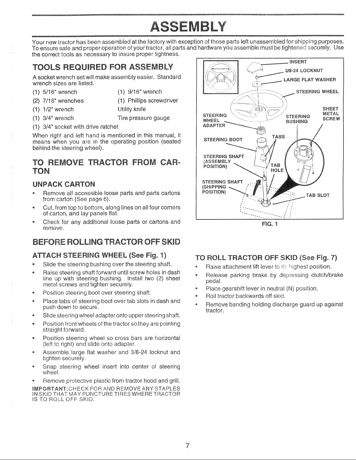
INSERT
TOOLS REQUIRED FOR ASSEMBLY
A socket wrench set will make assembly easier. Standard
wrench sizes are listed.
(1) 5/16" wrench
(2) 7/!6" wrenches
(1) 1/2" wrench
(t) 3/4" wrench
(1) 3/4" socket with drive ratchet
When right and _eft hand is mentioned in this manua!, it
means when you are in the operating position (seated
behind the steering wheel).
(1) 9/16" wrench
(1) Phillips screwdriver
Utility knife
Tire pressure gauge
STEERING
WHEEL o_
ADAPTER_
SHEET
STEERING SCREW
BUSHBNG
METAL
TO REMOVE TRACTOR FROM CAR-
TON
UNPACK CARTON
o Remove all accessible !oose parts and parts cartons
• Cut, from top to bottom, along [ines on all four corners
of carton, and lay panels flat.
• Check for any additional loose parts or cartons and
remove.
BEFORE ROLUNG TRACTOR OFF SKID
ATTACH STEERING WHEEL (See Fig. 1)
o Slide the steering bushing over the steering shaft.
* Raise steering shaft forward until screw holes in dash
line up with steering bushing, tnstal! two (2) sheet
metal screws and tighten securely,
o Position steering boot over steering shaft°
o Place tabs of steering boot over tab slots in dash and
push down to secure.
Slide steering wheel adapter onto upper steering shaft.
o Position front wheels of the tractor so they are pointing
straight forward.
Position steering wheel so cross bars are horizontal
(left to right) and slide onto adapter,
Assemble large flat washer and 3/8-24 [ocknut and
tighten securely
o Snap steering wheel insert into center of steering
wheel
o Remove protective piastic from tractor hood and griii.
IMPORTANT:CHECK FOR AND REMOVE ANY STAPLES
IN SKID THAT MAY PUNCTURE TIRES WHERE TRACTOR
IS TO ROLL OFF SKID,
TO ROLL TRACTOR OFF SKiD (See Fig. 7)
• Raise attachment lift lever to it, highest position.
® Reiease parking brake by depressing clutch/brake
pedal.
• Place gearshift lever in neutral (N) position.
o Roll tractor backwards off skid.
o Remove banding holding discharge guard up against
tractor.
Page 8
ASSE
HOW TO SET UP YOUR TRACTOR
PREPARE BATTERY (See Fig. 2)
CAUTION: Wear eye and face shield.
Wash hands or clothing immediately if
accidentally in contact with battery acid.
Do not smoke. Fumes from charged
battery acid are explosive.
Read the instructions included with the
battery vent caps. Always wear gloves,
cbthing and goggles to protect your
hands, skin and eyes,
Your tractor has a battery charging system which is suffi-
cient for normal use. However, periodic charging of the
battery with an automotive charger will extend its life.
° See instructions packed with vent caps in parts bag.
o Fiil battery with acid. Fill each cell until it reaches the
bottom of the vent wells. Do not overfill.
Allow battery to stand and settle for at least thirty
minutes. After standing, check the battery cell acid
!eve!. f below the vent we!!s, add more acid ,Jnti!the
correct level is reached.
While battery is standing (after adding acid) and later, while
battery is being charged, continue with assembly of tractor.
iMPORTANT: TO MAXIMIZE THE LIFE OF YOUR
BATTERY, IT IS NECESSARY THAT THE BATTERY BE
CHARGED BEFORE USE. FAILURE TO CHARGE
BATTERY CAN RESULT iN A SHORTENED BATTERY
LIFE.
* Charge battery at a rate of 6 amperes for 1 hour. Use
a t2 volt battery charger. Observe all safety precau-
tions required for battery charging.
o Check the acid level after the battery is charged, tf the
acid has fallen below the correct level, add distilled or
iron free water.
• hstalI the vent caps to cover the vent wells. Wash the
top of the battery with water to remove any acid, then
wipe dry.
o Check battery case for leakage to make sure that no
damage has occurred in handling.
o Dispose of excess battery acid. Neutralize acid for
disposal by adding it to two gallons of water in a five
gallon plastic container. Stir with a wooden or plastic
paddle while adding baking soda until the addition of
more soda causes no more foaming.
o Follow instructions on how to install battery.
CUT AWAY V_EW
FiG° 2
VENT CAP
VENT WELL
BATTERY CELL
ACID LEVEL
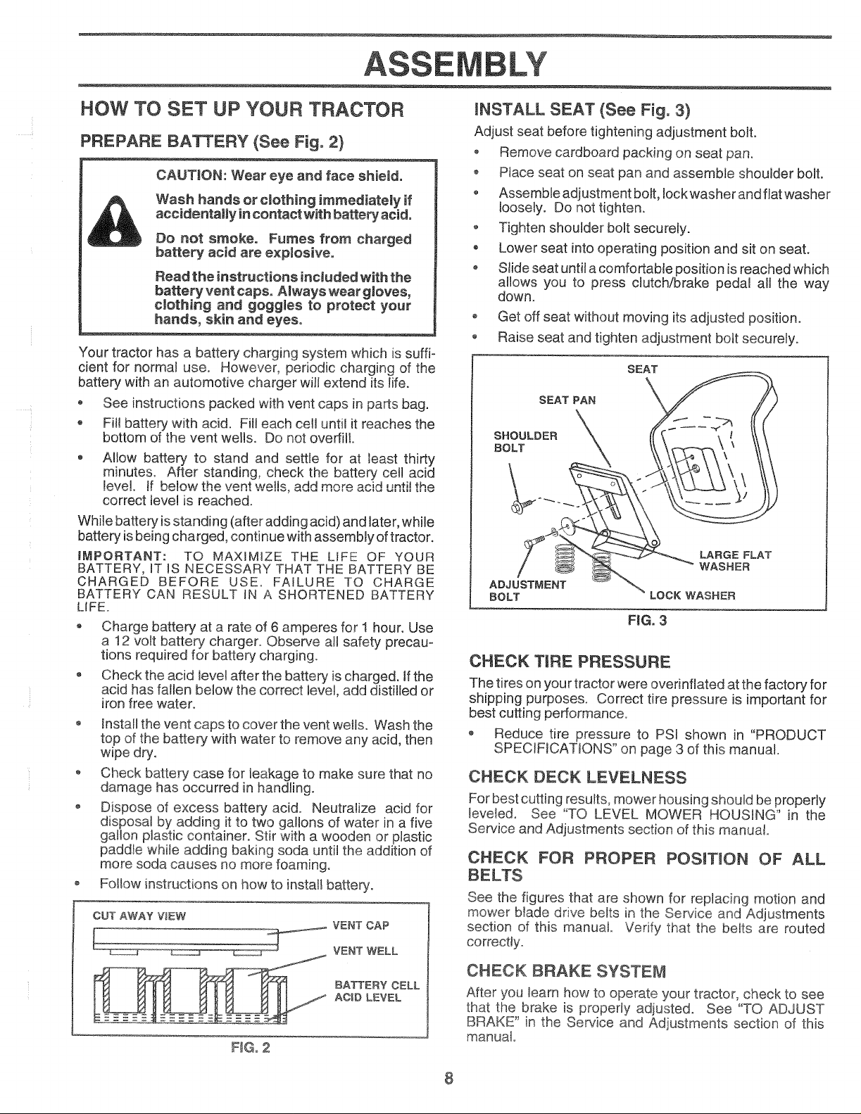
INSTALL SEAT (See Fig, 3)
Adjust seat before tightening adjustment bolt.
o Remove cardboard packing on seat pan.
o Place seat on seat pan and assemble shoulder bolt.
o Assemble adjustment bolt, Iockwasherandfiatwasher
loosely. Do not tighten.
o Tighten shoulder bolt securely.
Lower seat into operating position and sit on seat.
o Slide seat until a comfortable position is reached which
allows you to press clutch/brake pedal all the way
down.
o Get off seat without moving its adjusted position.
Raise seat and tighten adjustment bolt securely.
SEAT
SHOULDER X {{\ \ ! \\\
,,OLT \\ \\\
LARGE FLAT
WASHER
ADJUSTMENT
BOLT LOCK WASHER
FiG. 3
CHECK TiRE PRESSURE
The tires on your tractor were overinflated at the factory for
shipping purposes. Correct tire pressure is important for
best cutting performance.
o Reduce tire pressure to PSi shown in "PRODUCT
SPECIFICATIONS" on page 3 of this manual.
CHECK DECK LEVELNESS
For best cutting results, mower housing should be properly
leveted. See "TO LEVEL MOWER HOUSING" in the
Service and Adjustments section of this manual.
CHECK FOR PROPER POSnTION OF ALL
BELTS
See the figures that are shown for replacing motion and
mower blade drive belts in the Service and Adjustments
section of this manuai. Verify that the belts are routed
correcfly.
CHECK BRAKE SYSTEM
After you learn how to operate your tractor, check to see
that the brake is properly adjusted. See "TO ADJUST
BRAKE" in the Service and Adjustments section of this
manual°
8
Page 9
ASS LY
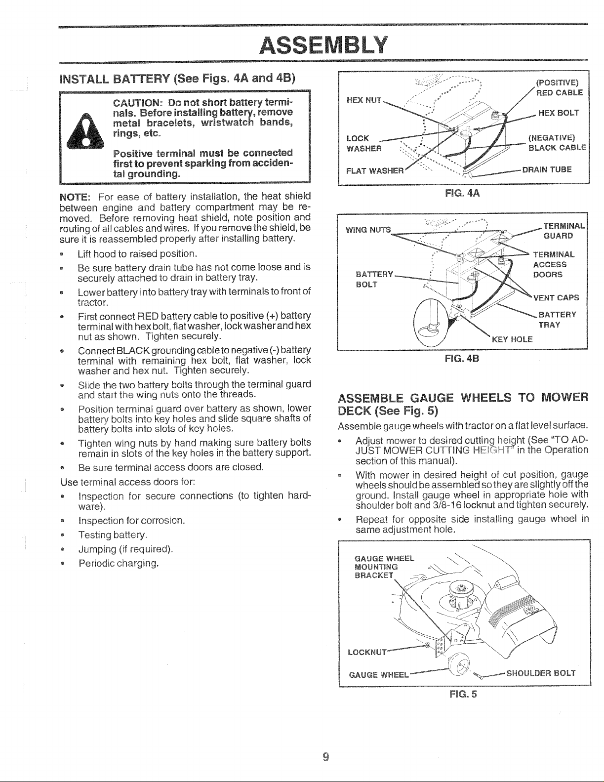
mNSTALL BATTERY (See Figs. 4A and 4B)
CAUTION: Do not short battery termi-
nals. Before installing battery, remove
metaJ bracemets, wristwatch bands,
rings, etco
Positive terminam must be connected
first to prevent sparking from acciden-
tamgrounding.
NOTE: For ease of battery installation, the heat shield
between engine and battery compartment may be re-
moved. Before removing heat shield, note position and
routing of aHcables and wires, ff you remove the shield, be
sure it is reassembled properly after installing battery°
o Lift hood to raised position.
o Be sure battery drain tube has not come loose and is
securely attached to drain inbattery tray.
Lower battery into battery tray with terminals to front of
tractor.
o First connect RED battery cable to positive (+) battery
terminal with hex boil fiat washer, Iockwasher and hex
nut as shown. Tighten securely.
Connect BLACK grounding cable to negative (-) battery
terminal with remaining hex bolt, fiat washer, lock
washer and hex nut. Tighten securely.
o Slide the two battery bolts through the terminal guard
and start the wing nuts onto the threads.
Position terminal guard over battery as shown, lower
battery bolts into key holes and slide square shafts of
battery bolts into slots of key holes.
Tighten wing nuts by hand making sure battery bolts
remain in slots of the key holes in the battery suppo£.
Be sure terminal access doors are dosed.
Use terminal access doors for:
hspection for secure connections (to tighten hard-
ware).
® Inspection for corrosion.
Testing battery.
Jumping (if required).
Periodic charging.
(POSmVE)
CABLE
REX BOLT
FLAT WASHER )RAIN TUBE
FiG. 4A
WnNG NUTS TERMINAL
o', GUARD
TERMINAL
ACCESS
DOORS
BOLT
CAPS
BATTERY
TRAY
ASSEMBLE GAUGE WHEELS TO MOWER
DECK {See Fig. 5)
Assemble gauge wheels with tractor on a flat level surface.
o Adiust mower to desired cutting height (See "TO AD-
JUST MOWER CUTTING HE;GHT" in the Operation
section of this manuat)o
o With mower in desired height of cut position, gauge
wheels should be assembled so they are slightly off the
ground. Install gauge wheel in appropriate hole with
shoulder bolt and 3/8ol 6 Iocknut and tighten securely.
Repeat for opposite side installing gauge wheel in
same adjustment hole.
GAUGE WHEEL
MOUNTING
BRACKET
9
LO(
GAUGE WHEEL
;ROULDER BOLT
FIG. 5
Page 10
ASSE LY
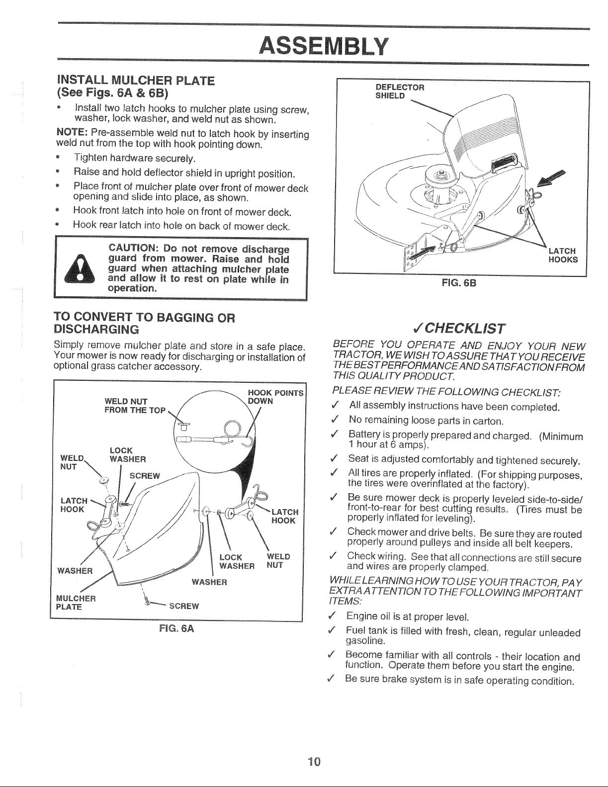
INSTALL MULCHER PLATE
(See Figs. 6A & 6B)
o lnstalt two latch hooks to muicher plate using screw,
washer, lock washer, and weld nut as shown.
NOTE: Pre-assemble weld nut to latch hook by inserting
weld nut from the top with hook pointing down.
Tighten hardware securely.
• Raise and hold deflector shield in upright position.
o Place front of mulcher plate over front of mower deck
opening and slide into place, as shown.
Hook front latch into hole on front of mower deck.
Hook rear latch into hole on back of mower deck.
CAUTION: Do not remove discharge
guard from mower. Raise and hold
guard when attaching mumcher plate
and atlow it to rest on plate while in
operation.
TO CONVERT TO BAGGING OR
DISCHARGnNG
,.,,,,,_,,y remove ,,,u_u__ p_t_ and store in a safe piace.
Your mower is now ready for discharging or installation of
optional grass catcher accessory.
HOOK POINTS
LOCK
WASHER
DOWN
HOOK
WELD
NUT
WELD NUT
FROM THE TOP
HOOK
MULCHER
PLATE
FmGo6A
LATCH
HOOKS
FiG. 6B
7CHECKMST
r_=_,qDE YOU OPERATE AND ENJOY YOUR NEW
TRA C"FOR, WE WISH TOASSURE THAT YOU RECEIVE
THE BESTPERFORMANCEAND SA TISFACTION FROM
"THISQUALITY PRODUCT.
PLEASE REVIEW THE FOLLOWING CHECKLIST:
,/ All assembly instructions have been completed.
,z No remaining loose parts in carton.
,/ Batteryis properly prepared and charged. (Minimum
! hour at 6 amps).
7 Seat is adjusted comfortably and tightened securely.
7 All tires are properly inflated. (For shipping purposes,
the tires were ovednfiated at the factory).
./ Be sure mower deck is properly leveled side-to-side/
front4o-rear for best cutting results. (Tires must be
properly inflated for leveling).
7 Check mower and drive belts. Be sure they are routed
propedy around pulleys and inside a!l belt keepers.
•/ Check wiring. See that all connections are still secure
and wires are properly clamped.
WHILE LEARNING HOW TO USE YOUR TRACTOR, PAY
EXTRAA TTENTtON TO THE FOLLOWING IMPORTANT
ITEMS:
7" Engine oil is at proper level.
7 Fuel tank is filled with fresh, clean, regular unleaded
gasoline.
,K Become famiiiar with all contro{s o their location and
function. Operate them before you start the engine.
,z Be sure brake system is in safe operating condition.
10
Page 11
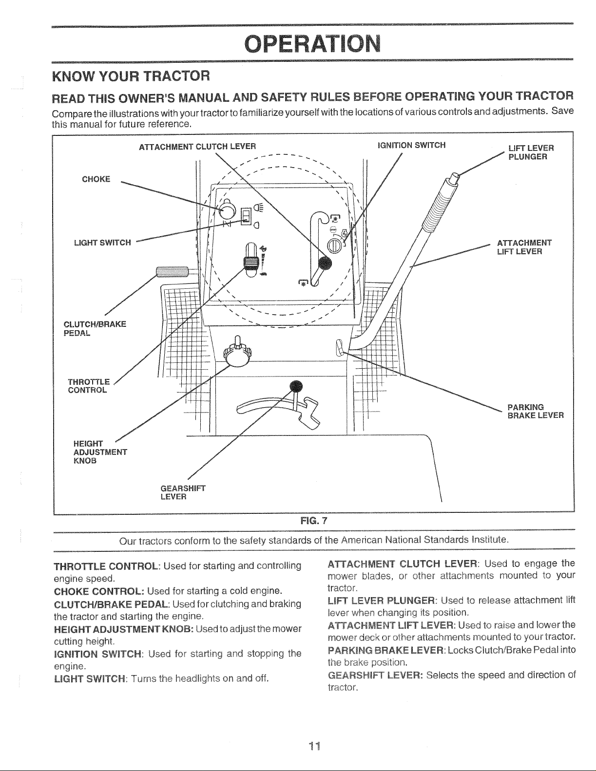
O ERATION
KNOW YOUR TRACTOR
READ THIS OWNER'S MANUAL AND SAFETY RULES BEFORE OPERATING YOUR TRACTOR
Compare the illustrations with your tractor to familiarize yourself with the locations of various controls and adjustments. Save
this manual for future reference.
CHOKE
\
\
UGHT SWITCH ATTACHMENT
CLUTCHIBBAKE
PEDAL
THBOTTLE
CONTROL
HEIGHT
ADJUSTMENT
KNOB
LiFT LEVEE
\
FIG. 7
Our tractors conform to the safety standards of the American National Standards Instituteo
THRO_LE CONTROL: Used for starting and controlling
engine speed.
CHOKE CONTROL: Used for starting a cold engine.
CLUTCH/BRAKE PEDAL: Used for clutching and braking
the tractor and starting the engine.
HEIGHT ADJUSTMENT KNOB: Used to adjust the mower
cutting height
IGN_TION SW_TCN: Used for starting and stopping the
engine.
LIGHT SWITCH: Turns the headlights on and off.
AT[ACHMENT CLUTCH LEVER: Used to engage the
mower biades, or other attachments mounted to your
tractor.
LI_ LEVER PLUNGER: Used to release attachment lift
tever when changing its position°
A_AOHME#,_T UFT LEVER: Used to raise and lower the
mower deck or other attachments mounted to your tractor.
PARKING BRAKE LEVER: Locks Clutch/Brake Pedal into
the brake position.
GEARSH_ LEVER: Selects the speed and direction of
tractor.
Page 12
PERATION
The operation of any tractor can result in foreign objects thrown into the eyes, which
can resumt in severe eye damage. Always wear safety 9Jasses or eye shields while
operating your tractor or performing any adjustments or repairs. We recommend a
wide vision safety mask for over the spectacles or standard safety glasses°
HOW TO USE YOUR TRACTOR
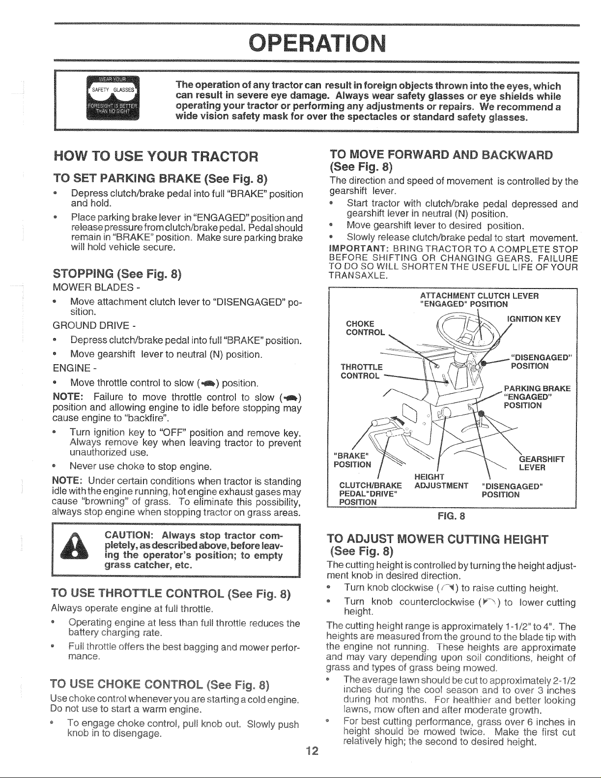
TO SET PARKING BRAKE (See Fig. 8)
o Depress clutch/brake pedal into full "BRAKE" position
and hold.
Place parking brake lever in "ENGAGED" position and
releasepressurefromclutch/brakepedaL Pedal should
remain in "BRAKE" position. Make sure parking brake
will hold vehicle secure.
STOPPING (See Fig. 8)
MOWER BLADES o
Move attachment clutch lever to "DISENGAGED" po-
sition.
GROUND DRWE o
Move gearshift lever to neutral (N) position.
ENGINE °
Move throttle control to slow (_) position.
NOTE: Failure to move throttle control to slow (,_)
position and allowing engine to idle before stopping may
cause engine to "backfire".
Turn ignition key to "OFF" position and remove key.
Always remove key when leaving tractor to prevent
unauthorized use.
o Never use choke to stop engine.
NOTE: Under certain conditions when tractor is standing
idle with the engine running, hot engine exhaust gases may
cause "browning" of grass To eliminate this possibility,
always stop engine when stopping tractor on grass areas.
TO MOVE FORWARD AND BACKWARD
(See Fig. 8)
The direction and speed of movement is controlled by the
gearshift lever°
o Start tractor with clutch/brake pedal depressed and
gearshift lever in neutral (N) position.
o Move gearshift lever to desired position.
Stowly release clutch!brake peda! to start movement.
IMPORTANT: BRING TRACTOR TO A COMPLETE STOP
BEFORE SHIFTING OR CHANGING GEARS. FAILURE
TO DO SO WILL SHORTEN THE USEFUL LIFE OF YOUR
TRANSAXLE.
ATTACHMENT CLUTCH LEVER
"ENGAGED" POSITION
CHOKE
CONTROL
THROTTLE
CONTROL
HEIGHT
CLUTCH/BRAKE ADJUSTMENT "D_SENGAGED"
PEDAL" DB_VE" POS_T_ON
POSfT_ON
F_G. 8
_GN_TION KEY
PosmoN
PARKING BRAKE
PosmoN
CAUTION: Always stop tractor com-
pletely, as described above, before leave
ing the operator's position; to empty
grass catcher, etc,
TO USE THROTTLE CONTROL (See Fig. 8)
Always operate engine at fuji throttleo
o Operating engine at _essthan full throttle reduces the
battery charging rate°
o Fuji throttie offers the best bagging and mower pertoro
mance.
TO USE CHOKE CONTROL (See Fig, 8)
Use choke contro_ whenever you are starting acold engine.
Do not use to start a warm engine°
o To engage choke control, pult knob out. Slowly push
knob in to disengage,.
TO ADJUST MOWER CUTTING HEIGHT
(See Fig. 8)
The cutting height is controlled by turning the height adjust-
ment knob in desired direction,
o Turn knob clockwise (f_) to raise cutting height.
o Turn knob counterclockwise (F_) to lower cutting
height.
The cutting height range is approximateJy 1o!/2" to 4" The
heights are measured from the ground to the blade tip with
the engine not running. These heights are approximate
and may vary depending upon soil conditions, height of
grass and types of grass being mowed.
o The average lawn should be cut to approximately 2--1/2
inches during the cool season and to over3 inches
during hot months. For healthier and better looking
lawns, mow often and after moderate growth.
o For best cutting performance, grass over 6 inches in
height should be mowed twice. Make the first cut
relatively high; the second to desired height.
12
Page 13
PERATION
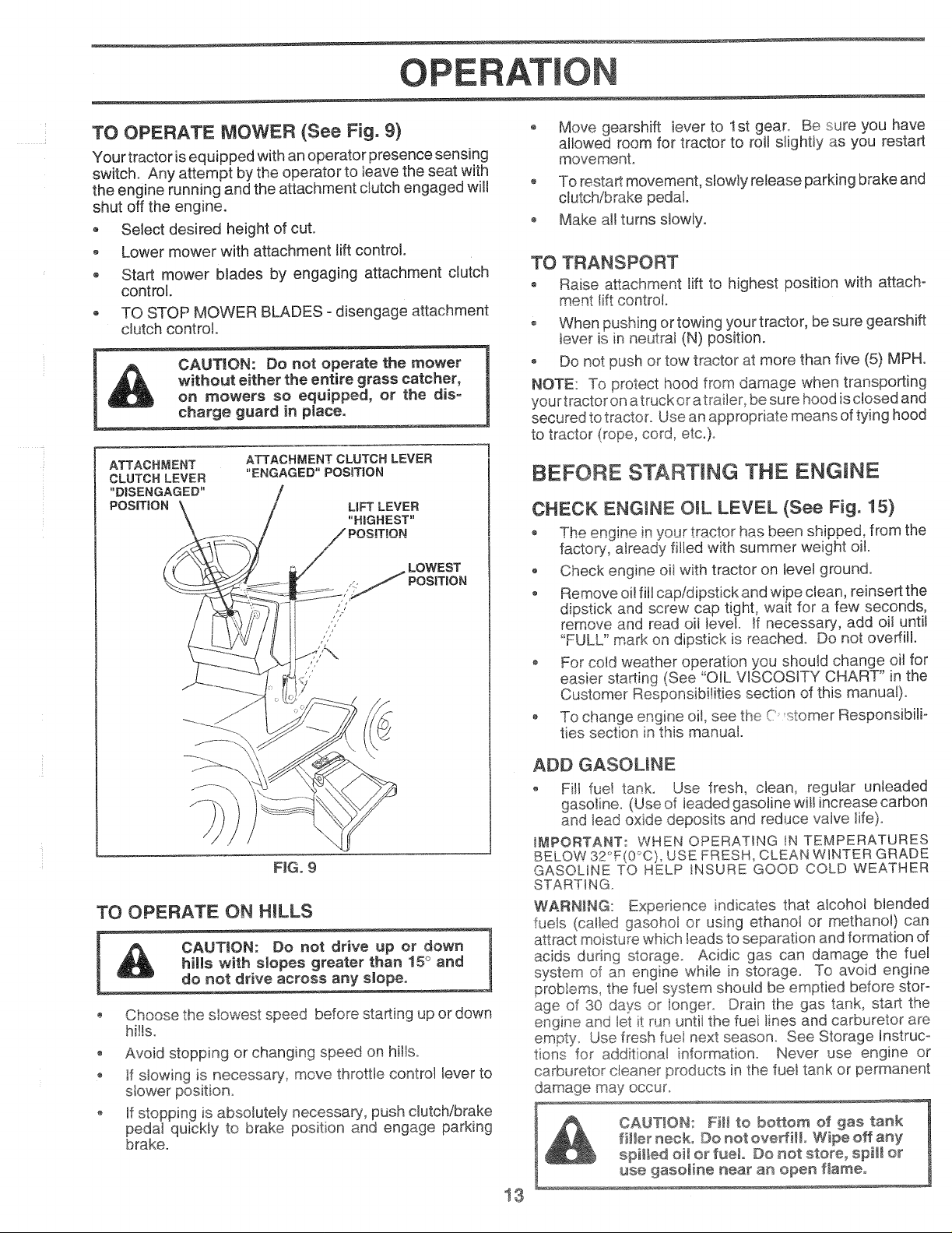
TO OPERATE MOWER (See Fig. 9)
Your tractor is equipped with an operator presence sensing
switch. Any attempt by the operator to leave the seat with
the engine running and the attachment clutch engaged will
shut off the engine.
• Select desired height of cut.
o Lower mower with attachment lift control
o Start mower blades by engaging attachment clutch
control.
TO STOP MOWER BLADES - disengage attachment
clutch control.
CAUT!ON: Do not operate the mower
without either the entire grass catcher,
on mowers so equipped, or the dis°
charge guard in pJaceo
ATTACHMENT
CLUTCH LEVER
"DISENGAGED"
POSITION
ATTACHMENT CLUTCH LEVER
"ENGAGED" POS_TION
/ L|FT LEVER"HIGHEST"
/ POS!T_ON
\
FIG. £
TO OPERATE ON HILLS
CAUTION: Do not drive up or down
hills with s_opes greater than 15° and
do not drive across any slopeo
Choose the s!owest speed before starting up or down
hills.
• Avoid stopping or changing speed on hills.
If slowing is necessary, move throttle control lever to
o If stopping is absolutely necessa_/, push clutch/brake
peda_ quickly to brake position and engage parking
brake.
Move gearshift iever to 1st gear. Be sure you have
allowed room for tractor to roll sHghtty as you restart
movement.
o To resta_ movement, slowly release parking brake and
clutch/brake pedal.
o Make all turns slowly.
TO TRANSPORT
o Raise attachment lift to highest position with attach-
ment lift control
o When pushing or towing your tractor, be sure gearshift
lever is in neutral (N) position.
o Do not push or tow tractor at more than five (5) MPH.
NOTE: To protect hood from damage when transporting
your tractor on a truck or atrailer, be su re hood is closed and
secured to tractor. Use an appropriate means of tying hood
to tractor (rope, cord, etc.).
BEFORE STARTING THE ENGINE
CHECK ENGINE OiL LEVEL (See Fig. 15)
o The engine inyour tractor has been sh pped from the
factory, atready filled with summer weight oil.
o Check engine oit with tractor on level ground.
Remove oil fill cap/dipstick and wipe clean, reinsert the
dipstick and screw cap tight, wait for a few seconds,
remove and read oit level. If necessary, add oil until
"FULL" mark on dipstick is reached. Do not overfill.
o For cold weather operation you should change oil for
easier starting (See "OIL VISCOSITY CHART" in the
Customer Responsibilities section of this manual).
To change engine oil, see the C stomer Responsibili-
ties section in this manual.
ADD GASOUNE
o Fill fuel tank_ Use fresh, clean, regular unleaded
gasoline. (Use of leaded gasolinewitt increase carbon
and lead oxide deposits and reduce valve tife)o
_MPORTANT: WHEN OPERATING IN TEMPERATURES
BELOW 32 (0 C) USE FRESH, CLEAN WINTER GRADE
GASOLINE TO HELP INSURE GOOD COLD WEATHER
STARTING.
WARNING: Experience indicates that alcohol blended
fuels (called gasohol or using ethano_ or methano!) can
attract moisture which _eadsto separation and formation of
acids during storage. Acidic gas can damage the fue!
system of an engine while Jn storage° To avoid engine
proMems, the fuel system should be emptied before stor-
age of 30 days or longer. Drain the gas tank, start the
engine and iet it run untii the fuei iines and carburetor are
empty_ Use fresh fue_ next season.. See Storage Instruco
tions for additional information° Never use engine or
carburetor cleaner products in the fuel tank or permanent
damage may occur°
filler neck. Do not ovedHL Wipe off any
f CAUTION: Fi_t to bottom of gas tank
13
spilled oi_ or fuel Do not store_ sp_m[or
use gasoline near an open flame°
Page 14
OPERATION
TO START ENGINE (See Fig. 8)
When starting engine for the first time or if engine has run
out of fueJ, it will take extra cranking time to move fuel from
the tank to the engine.
o Depress c_utchibrake pedal and set parking brake.
PJace gearshift lever in neutral (N) position,
Move attachment dutch to "DISENGAGED" position.
o Pull choke control out to choke 3osition for cold
engine start, For warm engine not use choke
control.
o Move throttle controJ to midway between fast (@) and
slow (_) positions.
Insert keyinto ignition and turn key clockwise to"START"
position and release key as soon as engine starts. Do
not run starter continuously for more than fifteen
seconds per minute. If engine does not start after
several attempts, move throttle contro! to fast (@)
position, wait a few minutes and try again.
When engine starts, slowly push choke control ino
o Move throttle control to fast (@Qposition°
o Allow engine to warm up for a few minutes before
engaging drive or attachments.
NOTE: If at a high altitude (above 3000 feet) or in cold
temperatures (below 32°F), the carburetor fuel mixture
may need to be adjusted for best engine performance. See
"TO ADJUST CARBURETOR" in the Service and Adjust-
ments section of this manual.
MOWmNG TiPS
Tire chains cannot be used when the mower housing
is attached to tractor.
o Mower should be properly leveled for best mowing
performance. See "TO LEVEL MOWER HOUSING" in
the Service and Adjustments section of this manual.
o The left hand side of mower should be used for trim°
ming.
• Drive so that clippings are discharged onto the area
that has been cut. Have the cut area to the right of the
machine. This will result in a more even distribution of
clippings and more uniform cutting.
o When mowing large areas, start by turning to the right
so that cJippings wilt discharge away from shrubs,
fences, driveways, etc. After one or two rounds, mow
in the opposite direction making left hand turns until
finished (See Fig. 10 ).
o If grass is extremely tall, it should be mowed twice to
reduce toad and possible fire hazard from dried clip-
pings. Make first cut relatively high; the second to the
desired height°
o Do not mow grass when it is wet. Wet grass will plug
mower and _eave undesirabb clumps. AHow grass to
dry before mowing.
o Always operate engine at full throttle when mowing to
assure be_er mowing performance and proper dis °
charge of material. Regulate ground speed by select o
ing a _ow enough gear to give the mower cutting
performance as well as the quality of cut desired.
o When operating attachments, select a ground speed
that will suit the terrain and give best performance of
the attachment being used.
FJGo10
MULCHING MOWING TIPS
iMPORTANT: FOR BEST PERFORMANCE, KEEP
MOWER HOUSING FREE OF BUILT-UP GRASS AND
TRASH, CLEAN AFTER EACH USE,
,,,= ou'=_,,_,mulching b_ue w,_ _uu_ uJ_ grass uu_-
pings many times and reduce them in size so that as
they fall onto the lawn they will disperse into the grass
and not be noticed. AJso, the mulched grass will
biodegrade quickly to provide nutrients for the Jawn.
Always mulch with your highest engine (blade) speed
as this will provide the best recutting action of the
blades.
o Avoid cutting your lawn when it iswet Wet grass tends
to form dumps and interferes with the mulching action.
The best time to mow your fawn is the early afternoon.
At this time the grass has dried and the newly cut area
wilJ not be exposed to the direct sun.
o For best results, adjust the mower cutting height so that
the mower cuts off only the top oneothird of the grass
blades (See Fig tl}o For extremely heavy mulching,
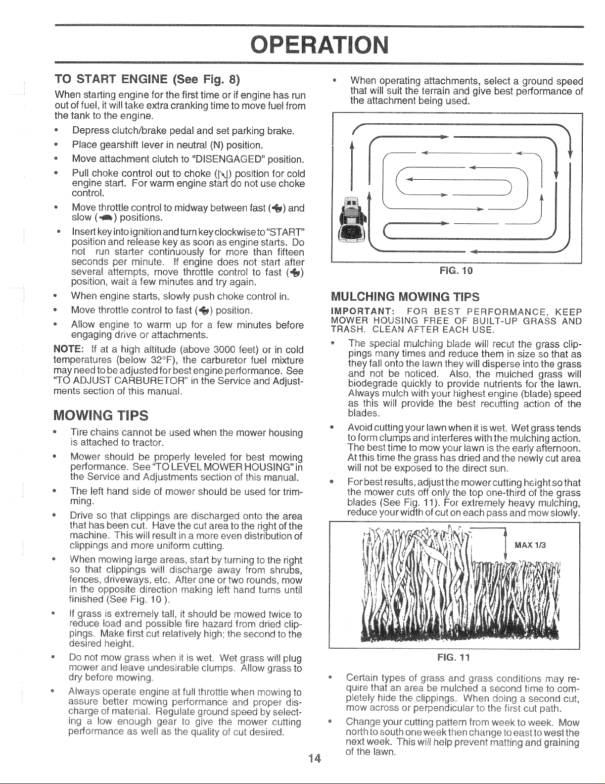
reduce your width of cut on each pass and mow stowly.
MAX 1/3
F_Go11
o Certain types of grass and grass conditions may re-
quire that an area be mu_ched a second time to com-
pletely hide the clippingso When doing a second cut,
mow across or perpendicular to the first cut path.
Change your cutting pattern from week to week. Mow
north to south one week then change to east towest the
next week° This witl he_pprevent matting and graining
14
of the lawno
Page 15
CUSTO ER
ES SI ES
AsYouCOMPLETE
o0ookorokoo0orot,on
R ShameniReplace Mower Blades _44
C Lubrication Chart .......
T Check Battery Level!Recharge _.
0 Clean Battery and Terminals
R Check Transaxb Cooting
Adjust Blade Belt(s) Tension
Adjust Motion Drive Belt(s) Tension
Check Engine OiJLevel
Change Engine Oil
C!ean Air Filter
N_ Cban Air Screen
7
----d(,----
G Inspect MuffieriSpark Attester
Replace Oil Filter (if equipped)
Clean Engine Cooling Fins
Replace Spark Plug
__, ...._Rep,aceAir FHterPaper Cartridge
* Change more often when operating under a hear
2 _Service more often when operating in dirty or dusty conditions.
load or in high ambient temperatures,
GENERAL RECOMMENDATIONS
The warranty on this tractor does not cover items that have
been subiected to operator abuse or negligence. To
receive full value from the warranty, operator must maintain
tractor as instructed in this manuak
Some adjustments will need to be made periodically to
propedy maintain your tractor.
All adjustments in the Service and Adjustments section of
this manuaJ should be checked at bast once each season.
Once a year you should replace the spark plug, ctean
or replace air fi!ter, and check blades and beJts for
wear. A new spark plug and dean air filter assure
proper aihfuel mixture and hetp your engine run better
and Jast longer.
3 - _fequipped with oil filter, change oil every" 50 hours,
4 _,Replace blades more often when mowing in sandy soif.
5 __f equipped with adjustable sy ;_:e;'rL
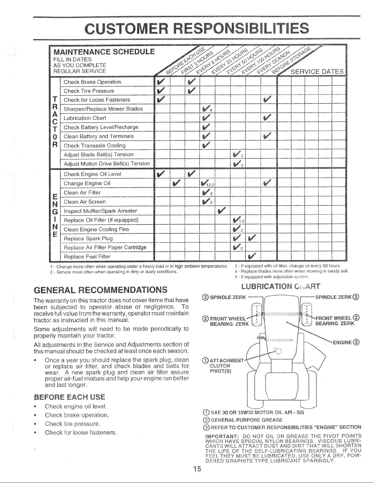
LUBRICATION C ART
P_NDLE ZERK (_
(_ FRONT WHEEL
BEARING ZERK BEARING ZERK
®
CLUTCH
P_VOT(S)
BEFORE EACH USE
o Check engine oil levek
Check brake operation.
o Check tire pressure
o Check for loose fasteners.
_) SAE 30 OR 10W30 MOTOR OIL AP_ oSG
GENERAL PURPOSE GREASE
_ REFER TO CUSTOMER RESPONS_BUUTUES "ENGINE" SECTION
_aPORTANT: DO NOT OIL OR GREASE THE PWOT POINTS
WHHCH HAVE SPECIAL NYLONBEAR_NGS. VISCOUS LUBRI-
CANTS WILL ATTRACT DUST AND DIRT THAT W_LL SHORTEN
THE LIFE OF THE SELF'oLUBRICAT_NG BEARINGS. IF YOU
FEEL THEY MUST BE LUBRICATED, USE ONLY A DRY, POW-o
DERED GRAPHITE TYPE LUBRICANT SPARINGLY.
Page 16

OUSTO RESPON ES
TRACTOR
Always observe safety rules when performing any mainte-
nance=
BRAKE OPERATION
If tractor requires more than six (6) feet stopping distance
at high speed in highest gear, then brake must be adjusted.
(See "TO ADJUST BRAKE" in the Service and Adjust-
ments section of this manual).
TmRES
o Maintain proper air pressure in all tires (See "PROD-
UCT SPECJHCATIONS" on page 3 of this manual).
Keep tires free of gasoline, oil, or insect control chemi-
cals which can harm rubber°
o Avoid stumps, stones, deep ruts, sharp objects and
other hazards that may cause tire damage.
BLADE CARE
For best results mower blades must be kept sharp. Re-
place bent or damaged blades.
BLADE REMOVAL (See Fig, 12)
- Raise mower to highest position to aiiow access to
blades.
Remove hex bolt, Iockwasher and flat washer securing
blade.
o Install new or resharpened blade with trailing edge up
towards deck as shown.
o Reassemble hex bolt, lock washer and ftat washer in
exact order as shown.
® Tighten bolt securely (30°35 Ft. Lbs. torque).
iMPORTANT: BLADE BOLT ISGRADE 8 HEATTREATED.
NOTE: We do not recommend sharpening blade- but if you
do, be sure the btade is balanced.
MANDREL
ASSEMBLY
FLAT WASHER
BLADE
TO SHARPEN BLADE (See Fig, 13)
Care should be taken to keep the blade balanced. An
unbalanced blade wilt cause excessive vibration and even-
tual damage to mower and engine°
o The blade can be sharpened with a file or on a grinding
wheel. Do not attempt to sharpen white on the mower.
To check blade balance you will need a 5/8" diameter
steel bolt, pin, ora cone balancer. (When using a cone
balancer, follow the instructions supplied with baF
Slide blade on to an unthreaded portion of the steel bolt
or pin and hold the bolt or pin paralle! with the ground.
If btade is balanced, it should remain in a horizontal
position. If either end of the blade moves downward,
sharpen the heavy end until the bIade is balanced.
NOTE: Do not use a nail for balancing blade. The lobes of
the center hole may appear to be centered, but are not.
/ •
5/8" BOLT
OR PiN
FtGo 13
BATTERY (See Fig, 14)
Your tractor has a battery charging system which is suffi-
cient for normal use. However, periodic charging of the
battery with an automotive charger will extend its life.
o Acid solution leve_in each battery cell should be even
with bottoms ofvent welts. Add only distilled or iron free
water if necessary. Do not overfill.
, Keep battery and terminals dean.
• Keep battery bolts tight.
Keep vent caps tight and small vent holes in caps open.
o Recharge at 6 amperes for 1 hour.
LOCK WASHER
°oxC:----- /
(GRADE8)_
_r_ 8 HEAT TREATED BOLT CAN BE _DENTiFiED
BY SiX UNES ON THE BOLT HEAD.
FtGo 12
TRAnLING EDGE
16
CUT AWAY ViEW
F_Go14
VENT CAP
VENT
BATTERY
CELL ACiD
WELL
LEVEL
Page 17
E ILITIES
TO CLEAN BATTERY AND TERMINALS
Corrosion and dirt on the battery and terminals can cause
the battery to "leak" power.
o Remove terminal guard.
o Disconnect BLACK battery cable first then RED
battery cable and remove battery from tractor.
o Wash battery with solution of four tablespoons of
baking soda to one gallon of water. Be careful not to
get the soda solution into the cells.
o Rinse the battery with plain water and dry.
Ctean terminals and battery cable ends with wire brush
unti! bright.
Coat terminals with grease or petroleum jelly.
Reinstall battery, (See "INSTALL BATTERY" in the
Assembly section of this manuat)o
VoBELTS
Check V-belts for deterioration and wear after 100 hours of
operation and replace if necessary. The belts are not
adjustable, Replace belts if they begin to slip from wear,
TRANSAXLE COOUNG
Keep transaxle free from build-up of dirt and chaff which
can restrict cooling,
ENGINE
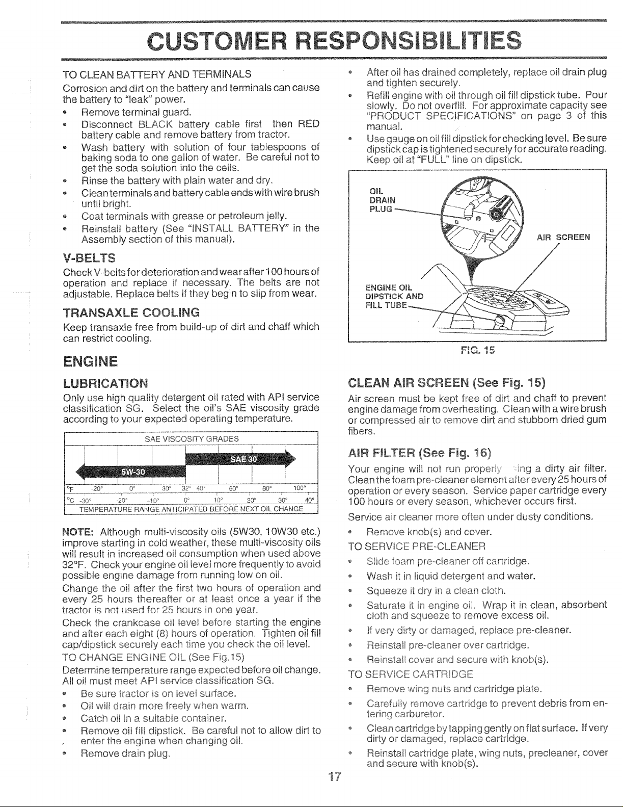
After oil has drained completely_ replace oil drain plug
and tighten securely.
o Refill engine with oit through oil fill dipstick tube. Pour
slowly. Do not overlie For approximate capacity see
"PRODUCT SPEC!FICATIONS" on page 3 of this
manual.
o Use gauge on oil fill dipstick for checking level. Besure
dipstick cap istightened securely for accurate reading.
Keep oil at "FULU _line on dipstick.
OIL
DRA_N
AIR SCREEN
ENGINE O_L
DIPSTICK AND
F_t2_ _ ,t_
LUBRICATION
Only use high quality detergent oil rated with API service
classification SG. Select the oi!'s SAE viscosity grade
according to your expected operating temperature,
SAE VISCOSITY GRADES
_20 ° 0_* 30 ° 32 ° 40 _ 60 _ 80 ° 100 °
°c -soo _oo o° _oo doo 4?°
TEMPERATU£E RANGEANTICIPATEDBEFORENEXTOtLCHANGE
NOTE: Although multi-viscosity oils (5W30, 10W30 etc.)
improve starting in cold weather, these multioviscosity oils
will result in increased oit consumption when used above
32°F. Check your engine oil ievei more frequently to avoid
possible engine damage from running low on oi!.
Change the oil after the first two hours of operation and
every 25 hours thereafter or at least once a year if the
tractor is not used for 25 hours in one year,
Check the crankcase oil level before starting the engine
and after each eight (8) hours of operation. Tighten oil fiJ!
cap/dipstick securely each time you check the oil leve!.
TO CHANGE ENGINE OIL (See Fig.15)
Determine temperature range expected before oil change.
All oil must meet API service classification SG.
o Be sure tractor is on level sudaCeo
Oit wiaIdrain more freely when warm.
Catch oil in a suitabte container.
o Remove oil fill dipstick. Be careful not to allow dirt to
enter the engine when changing oik
o Remove dran ptug.
CLEAN AIR SCREEN (See Fig, 15)
Air screen must be kept free of dirt and chaff to prevent
engine damage from overheating. Clean with a wire brush
or compressed air to remove dirt and stubborn dried gum
fibers.
AIR FILTER (See Fig, 16)
Your engine witl not run prope Iy nga dirty air filter.
Clean the foam preocteaner element after every 25 hours of
operation or even! season Service paper cartridge every
100 hours or ever>, season, whichever occurs first.
Service air cleaner more often under dusty conditions.
• Remove knob(s) and cover.
TO SERVICE PRE-CLEANER
o %ide foam preocteaner off cartridge.
o Wash it in liquid detergent and water.
o Squeeze it dp/in a dean cloth°
o Saturate t in engne oil. Wrap it in clean, absorbent
cloth and squeeze to remove excess oiL
o If very dirty or damage€ replace preocleaner.
o Reinstall precieaner over cartridge.
Reinstat cover and secure with knob(s).
TO SERVICE CARTRIDGE
o Remove wng nuts and cartridge plate.
o Carefui y remove cartridge to prevent debris from eno
tering carbureton
o Clean cartridge bytapping gently on fiat surface. _fvery
dirty or damaged, replace cartridge°
o Reinsta!! cartridge p]ate_ wing nuts, precleaner, cover
and secure with knob(s).
i7
Page 18

CU RESPON ILm
iMPORTANT: PETROLEUM SOLVENTS, SUCH AS
KEROSENE, ARE NOT TO BE USED TO CLEAN THE
CARTRIDGE. THEY MAY CAUSE DETERIORATION OF
THE CARTRIDGE, DO NOT OIL CARTRIDGE. DO NOT
USE PRESSURIZED AIR TO CLEAN OR DRY
CARTRIDGE.
KNOB - .....
COVER
MUFFLER
Inspect and replace corroded muffler and spark attester (if
equipped) as it could create a fire hazard and!or damage.
SPARK PLUGS
Replace spark plugs at the beginning of each mowing
season or after even/100 hours of use, whichever comes
first. Spark plug type and gap setting is shown in "PROD-
UCT SPECIFICATIONS" on page 3 of this manual.
IN-LINE FUEL FILTER (See Fig, 18)
The fuel filter should be replaced once each season. If fuel
filter becomes clogged, obstructing fuel flow to carburetor,
replacement is required.
o With engine cool, remove filter and plug fuel line
sections.
• Place new fuel filter in position in fuel line with arrow
pointing towards carburetor.
• Be sure there are no fuel line leaks and clamps are
properly positioned.
o Immediately wipe up any spilled gasoline.
CLAMP CLAMP
FiG. 16
ENGmNE COOLING FINS (See Fig. 17)
Remove any dust, dirt or oil from engine cooling fins to
prevent engine damage from overheating. Air guide covers
must be removed. Remove side panels and hood (See "TO
REMOVE HOOD AND GRILL ASSEMBLY" in the Service
and Adjustments section of this manual).
TOP A_R
GUKDE
ENGgNE
COOMNG FINS
FILTER
FJGo18
CLEANING
o Clean engine, battery, seat, finish, etc. of all foreign
matter.
o Keep finished surfaces and wheels free of all gasoline,
oil, etc.
o Protect painted surfaces with automotive type wax.
We do not recommend using a garden hose to clean your
tractor unless the electrical system, muffler, air filter and
carburetor are covered to keep water out. Water in engine
can result in a shortened engine life.
A_R GUIDE COVER
(BOTH SIDES)
F_Go!7
4@
Page 19

TRACTOR
SERVICE ADJUSTM
CAUTION: BEFORE PERFORMING ANY SERVICE OR ADJUSTMENTS:
, Depress dutch/brake peda_fully and set parking brake°
* Place gearshift lever in neuttat (N) position.
, Ptace attachment dutch in "DISENGAGED" position.
, Turn ignition key "OFF" and remove key.
, Make sure the blades and a_l moving parts have comp_etemy stopped.
® Disconnect spark plug wire from spark pmugand ptace wire where it cannot come in contact with
plug.
TO REMOVE MOWER (See Fig. 19)
Mower witi be easier to remove from the right side oftractor.
• Ptace attachment clutch in "D_SENGAGED" position.
o Move attachment lift lever fo_ard to lower mower to its
lowest position.
• Roll belt off engine pulley.
• Disconnect clutch rod from clutch lever by removing
retainer spring.
• Disconnect anti-sway bar from chassis bracket by
removing retainer spring.
® Disconnect suspension arms from rear deck brackets
by removing retainer springs.
Disconnect front links from deck by removing retainer
springs.
• Raise lift lever to raise suspension arms. Stide mower
out from under tractor.
iMPORTANT: IF AN ATTACHMENT OTHER THAN THE
MOWER iS TO BE MOUNTED TO THE TRACTOR, THE
R.H. AND LH. SUSPENSION ARMS MUST BE REMOVED
FROM TRACTOR.
TO iNSTALL MOWER (See Fig. 19)
Raise attachment lift lever to its highest position.
o Siide mower under tractor with discharge guard to right
side of tractor.
o Lower lift tever to its lowest position.
Install mower in reverse order of removal instructions.
CLUTCH
SUSPENSION
ARMS
RETABNER
SPRING
iTCH LEVER
PULLEY
;PRINGS
(BOTH SIDES)
FIG. 19
19
Page 20

SERVICE AN ADJUSTMENTS
TO LEVEL MOWER HOUSING
Adjust the mower while tractor is parked on level ground or
driveway. Make sure tires are properly inflated (See
"PRODUCT SPECIFICATIONS" on page 3). ff tires are
over or under inflated, you will not properly adjust your
mower.
SIDE-TO-SiDE ADJUSTMENT (See Figs. 20 and 21)
You will need two (2) standard 2 x 4 short pieces of wood
to make the following adjustment° Similar blocks measur-
ing 1ol/2" thick may also be used.
• Raise mower with attachment lift control to allow two
(2) 1ot/2" thick blocks to be placed under rear edge of
mower.
o Place one block directly behind the left mandrel. PJace
the remaining block under the stamped ridge on the
right rear edge of mower deck.
• Lower mower deck to its lowest height of cut posi!!on
(See "TO ADJUST MOWER CUTTING HEIGHT in
Operation section of this manual).
• On both sides of tractor, loosen, but do not remove, the
fasteners securing the adjustable pivot brackets to
frame. Both brackets must be loose enough to move
freely.
Pull down firmly on suspension arm to remove any
slack in pivot bracket and hold while tightening rear
fastener first to secure. Tighten remaining fastener.
, Repeat procedure on other side of tractor.
, Raise mower with attachment lift control and remove
blocks from under mower_
FRONT-TO-BACK ADJUSTMENT (See Figs. 22 and 23)
IMPORTANT: DECK MUST BE LEVEL SIDE-TO-SiDE. IF
THE FOLLOWING FRONT-TO-BACK ADJUSTMENT IS
NECESSARY, BESURE TO ADJUST BOTH FRONT LINKS
EQUALLY SO MOWER WILL STAY LEVEL SIDE-TO-
SIDE.
To obtain the best cutting results, the mower housing
should be adjusted so that the front is approximately 1/4" to
3/4" lower than the rear when the mower is in its highest
position.
Check adjustment on right side of tractor. Measure dis-
tance "D" directly in front and behind the mandre_ at bottom
edge of mower housing as shown°
* Before making any necessary' adjustments, check that
both front links are equal in length. Both links should
be approximately 10-3/8"o
* if links are not equat in length, adjust one link to same
length as other link.
* To lower front of mower loosen nut 'E" on both front
links an equal number of turns.
* When distance "D" is 1/4" to 3/4" lower at front than
rear, tighten nuts F" against trunnion on both front
links.
* To raise front of mower, loosen nut"F" from trunnion on
both front tinks. Tighten nut "E" on both front links an
equal number of turns.
o When distance "D" is 1/4" to 3/4" lower at front than
rear, tighten nut "F_against trunnion on both front links.
Recheck side-to-side adjustment.
PLACE TWO (2} 1-1/2" THnCK BLOCKS UNDER REAR EDGE OF
DECK (USE WOOD 2 X 4'S OR EQUIV.)
DIRECTLY
=, (,, ,
STA_
MOWER MUST BE iN LOWEST HEIGHT OF CUT POSITION
FJGo20
ADJUSTABLE PmVOT
BRACKET
FASTENERS
SUSPENSION
FIG, 22
BOTH FRONT UNKS MUST BE EQUAL _N LENGTH
/
NUT "E"
NUT "F" _"_
PULL DOWN AND T_GRTEN
REAR FASTENER FRST
FRONT UNKS
TRUNNUON
Page 21

SERVICE
TO REPLACE MOWER BLADE DRIVE BELT
(See Fig. 24)
The mower blade drive belt may be replaced without tools.
Park the tractor on level surface. Engage parking brake.
BELT REMOVAL
Place attachment clutch in "DISENGAGED" position.
Move attachment lift lever for¢Tard to lower mower to its
lowest position.
, Rol! belt off engine pulley.
o Work belt off both mandrel pufleys and idler pulleys.
Pull be!t away from mower.
BELT INSTALLATION -
, tnstali new bett in reverse order of removal.
• Make sure belt is in all pulley grooves and inside all belt
guides.
ENGINE PULLEY
MANDREL
PULLEY
iDLER
PULLEYS
\
\\
MANDREL PULLEY
FIG° 24
WITH PARKING BRAKE "ENGAGED"
\
OPERATING
ARM
F_G°25
TO REPLACE MOTION DRIVE BELT
(See Fig. 26)
Park the tractor on level surface, Engage parking brake.
For assistance, there is a belt installation guide decal on
bottom side of ieft footrest.
• Remove mower (See "TO REMOVE MOWER" in this
section of this manual.)
Remove upper belt keeper.
Remove belt from stationary idler and clutching idler.
• Putl belt slack toward rear of tractor. Remove belt
upwards from transaxle pulley by deflecting belt keep-
ers.
o Pult belt toward front of tractor and remove downwards
from around engine pulley.
o Install new belt by reversing abuve procedure.
IMPORTANT: MAKE SURE UPPER BELT KEEPER IS
POSITIONED PROPERLY BETWEEN LOCATOR TABS.
TO ADJUST BRAKE (See Fig, 25)
Your tractor is equipped with an adjustable brake system
which is mounted on the right side of the transaxte.
If tractor requires more than six (6) feet stopping distance
at high speed in highest gear, then brake must be adjusted.
o Depress clutch/brake pedal and engage parking brake.
Measure distance between brake operating arm and
nut "A" on brake rod.
o If distance is other than lq/2", disengage parking
brake, !oosen iam nut and turn nut "A" unti! distance
becomes 1_-1/2'L Retighten jam nut against nut "A".
Engage parking brake and recheck distance.
o Road test tractor for proper stopping distance as stated
above. Readjust if necessary, tf stopping distance is
stiff greater than six (6) feet in highest gear, fu_her
maintenance is necessary. Contact your nearest
authorized service center/departmento
EN_
PULLEY
CLUTCHING TABS
(DLER
BELT
KEEPER
iDLER
TRANSAXLE_
PULLEY
F_Go26
21
Page 22

E ADJUSTME
TO ADJUST STEERING WHEEL ALIGNMENT
If steering wheel crossbars are not horizonta! (!eft to right)
when wheels are positioned straightforward, removesteer-
ing wheel and reassemble per instructions in the Assembty
section of this manual.
FRONT WHEEL TOE++N!CAMBER
The front wheel toe-in and camber are not adjustable on
your tractor. If damage has occurred to affect the front
wheel toe-in or camber, contact your nearest authorized
service center.
TO REMOVE WHEEL FOR REPAIRS
(See Fig. 27}
® Block up axle securely.
, Remove axle cover, retaining ring and washers to allow
wheet removal (rear wheel contains a square key -Do
not lose).
, Repair tire and reassemble.
• On rear wheels only: align grooves in rear wheel hub
and axle. Insert square key.
+ Replace washers and snap retaining ring securely in
axle groove.
+ Replace axle cover.
WASHERS
TO START ENGINE WroTHA WEAK BATTERY
(See Fig. 28}
CAUTION: Lead-acid batteries gener-
ate explosive gases. Keep sparks, flame
and smoking materiaJs away from bat-
teries. A_ways wear eye protection
when around batteries°
If your battery is too weak to start the engine, it should be
recharged, if "jumper cables" are used for emergency
starting, follow this procedure:
IMPORTANT: YOUR TRACTOR IS EQUIPPED WITH A 12
VOLT NEGATIVE GROUNDED SYSTEM. THE OTHER
VEHICLE MUST ALSO BE A 12 VOLT NEGATIVE
GROUNDED SYSTEM. DO NOT USEYOURTRACTOR
BATTERY TO START OTHER VEHICLES.
TO ATTACH JUMPER CABLES -
, Connect each end of the RED cable to the POSITIVE
(+) terminal of each battery, taking care not to short
against chassis.
+ Connect one end of the BLACK cable to the NEGA-
TIVE (-) terminal of fully charged battery.
- Connect the other end of the BLACK cable to good
TO REMOVE CABLES, REVERSE ORDER -
, BLACK cabte first from chassis and then from the fully
charged battery,.
, RED cable last from both batteries.
AXLE COVER
FIG. 27
22
"POSITWE" (+}
"NEGATWE" (-}
FIGo 28
Page 23

S iCE
ADJU
TO REPLACE HEADLIGHT BULB
, Raise hood.
• Pull bulb ho!der out of the hole in the backside of the
grill.
Repgace bulb in holder and push bulb holder securely
back into the hole in the backside of the grill°
, Close hood.
iNTERLOCKS AND RELAYS
Loose or damaged wiring may cause your tractor to run
poody, stop running, or prevent it from starting.
® Check wiring. See electficaJ wMng diagram in Repair
Parts section of this manual.
TO REPLACE FUSE
Replace with 30 amp automotive-type plug-in fuse. The
fuse holder is located behind the dash.
TO REMOVE HOOD AND GRILL (See Fig° 2g}
,, Raise hood.
Unsnap headlight wire connector.
• Stand in front of tractor. Grasp hood at sides, tilt
forward and lift off of tractor.
To reinstall, slide hood pivot brackets into slots in
frame.
Reconnect headlight wire connector and close hood.
ENGINE
TO ADJUST THROTTLE CONTROL CABLE
(See Fig, 30}
The throttle control has been preset at the factory and
adjustment should not be necessary'. Check adjustment as
described below before _oosening cable. If adjustment is
necessary, proceed as follows:
, With engine not running, move throttle control ]ever to
fast (,@) position.
o Check that swivel is against side of quarter circle. If it
is not, loosen cable clamp screw and pult cable back
until swivel is against quarter circle. Tighten cable
clamp screw securely.
TO ADJUST CHOKE CONTROL (See Fig. 31}
The choke control has been preset at the factory and
adjustment should not be necessary. Check adjustment as
described below before _oosening cable if adjustment is
necessary, proceed as follows:
o With engine not running, move choke control (located
on dash panel) to fu!l choke (IXi) position.
, Remove air cleaner cover, filter and cartridge plate to
expose carburetor choke (see "AIR FILTER" in the
Customer Responsibilities section of this manual).
• Choke shou!d be closed. If it is not, loosen casing
clamp screw and move choke cable until choke is
completely ctosed. Tighten casing clamp screw se-
curely.
Reassemble air cleaner.
HOOD
CLAMP SCREW
/
HEADLIGHT
WiRE
CONNECTOR
SWmVEL
F_Go29
Page 24

E CE AN ADJ ENTS
TO ADJUST CARBURETOR
(See Figs. 32 and 33)
The carburetor has been preset at the factory and adjust-
ment should not be necessary. However, minor adjust-
ment may be required tocompensate for differences infuel,
temperature, altitude or load. If the carburetor does need
adjustment, proceed as follows:
]n general, turning the mixture screw in (clockwise) de-
creases the supply of fuel to the engine giving a leaner fuel/
air mixture Turning the mixture screw out (counterctocko
wise) increases the supply of fuel to the engine giving a
richer fuel/air mixture.
IMPORTANT: DAMAGE TO THE NEEDLES AND THE
SEATS tN CARBURETOR MAY RESULT IF SCREW IS
TURNED tN TOO TIGHT.
PREUMINARY SE_ING o
Be sure you have a clean air filter, and the throttle
contro_ cable and choke are adjusted properly (see
above).
o With engine off turn idle mixture screw in (clockwise)
closing it finger tight and then turn out (counterclock-
wise) 1-t/4 to 1-1/2 turns.
FINAL SETTING o
• Start engine and aiiow to warm for five minutes. Make
final adjustments with engine running and shift/motion
control lever in neutral (N) position.
o With throttle control lever in slow (_) position, hold
throttle lever against idle speed screw and adjust idle
speed screw to obtain 1200 to !400 RPM
• While stir holding throttle lever against idle speed
screw, turn idle mixture screw in (clockwise) until
engine begins to die and then turn out (counterclock-
wise) untit engine runs rough. Turn screw to a point
midway between those two positions.
o Continue to hold throttle lever against idle speed screw
and adjust idle speed screw to obtain 900to 1200 RPM.
Release throttle lever.
ACCELERATION TEST-
Move throttle control lever from slow (_) to fast (,1_)
position. If engine hesitates or dies, turn idle mixture
screw out (counterclockwise) 1/8 turn° Repeat test
and continue to adjust, ifnecessary, until engine accel-
erates smootNyo
High speed stop is factory' adjusted. Do not adjust -
damage may result.
iMPORTANT: NEVER TAMPER WITH THE ENGINE
GOVERNOR, WHICH IS FACTORY SET FOR PROPER
ENGINE SPEED. OVERSPEEDING THE ENGINE ABOVE
THE FACTORY HiGH SPEED SETTING CAN BE
DANGEROUS. IFYOU THJNKTHE ENGINEoGOVERNED
HIGH SPEED NEEDS ADJUSTING, CONTACT YOUR
NEAREST AUTHORIZED SERVlCE CENTER/
DEPARTMENT, WHICH HAS PROPER EQUIPMENT AND
EXPERIENCE TO MAKE ANY NECESSARY
ADJUSTMENTS,
IDLE SPEED
SCREW
THROTTLE
LEVER
RG. 32
iDLE SPEED
THROTTLE
LEVER
FJGo33
24
Page 25

STO
Immediately prepare your tractor for storage at the end of
the season or if the tractor will not be used for 30 days or
more,
,_ _, _ea building t
each an.°Penflame l
_ thee ngine to cool
......... beforestoring in any enclosure°
TRACTOR
Remove mower from tractor for winter storage. When °
mower is to be stored for a period of time, clean it thor°
oughly, remove ali dirt, grease, leaves, etc. Store in a
clean, dry area.
Clean entire tractor (See"CLEANiNG" in the Customer
Responsibilities section of this manual), o
o Inspect and replace belts, if necessary (See belt re-
placement instructions in the Service and Adjustments
section of this manual).
Lubricate as shown in the Customer Responsibilities
section of this manual.
Be sure that all nuts, bolts and screws are securely
fastened° Inspect moving parts for damage, breakage
and wear. Replace if necessary.
o Touch up nil rusted or chipped paint surfaces; sand
light!y before painting
BATTERY
° Fully charge the battery for storage
• After a period of time in storage, battery may require
recharging.
o To hetp prevent corrosion and power leakage during
tong periods of storage, battery cables should be
disconnected and battery cleaned thoroughly (see"TO
CLEAN BATTERY AND TERMINALS" in the Cus-
tomer Responsibilities section of this manual).
After cleaning, leave cables disconnected and place
cables where they cannot come in contact with battery
terminals.
® Be sure battery drain tube issecurely attached.
o If battery is removed from tractor for storage, do not
store battery directly on concrete or damp surfaces.
ENGINE
FUEL SYSTEM
_MPORTANT: IT IS IMPORTANT TO PREVENT GUM
DEPOSITS FROM FORMING JN ESSENTIAL FUEL
SYSTEM PARIS SUCH AS CARBURETOR, FUEL FILTER,
FUEL ROSE, OR TANK DURtNG STORAGE. ALSO,
EXPERIENCE _NDICATES THAT ALCOHOL BLENDED
FUELS (CALLED GASOHOL OR USING ETHANOL OR
METHANOL) CAN ATTRACT MOISTURE WHICH LEADS
TO SEPARATION AND FORMATION OF ACIDS DURING
STORAGE. ACIDIC GAS CAN DAMAGE THE FUEL
SYSTEM OF AN ENGINE WH_LE tN STGRAGE.
Drain the fuet tank
Start the engine and let it run until the fuel lines and
carburetor are empty.
Never use engine orcarburetor cleaner products in the
fuel tank or permanent damage may occur.
Use fresh fue_ next season.
NOTE: Fuel stabilizer is an acceptable alternative in
minimizing the formation of fuel gum deposits during stor-
age. Add stabilizer to gasoline in fuel tank or storage
container. Always follow the mix ratio found on stabilizer
container. Run engine at !east 10 minutes after adding
stabilizer to allow the stabilizer to reach the carburetor° Do
not drain the gas tank and carburetor ifusing fuel stabilizer.
ENGINE OIL
Drain oii (with engine warm) and replace with ctean engine
oi!. _,'_ee EN_.N,o in the Customer Responsibilities
section of this manual)o
CYUNDERS
, Remove spark plug(s).
o Pour one ounce of oit through spark p_ughole(s) into
Turn ignition key to "START" position for afew seconds
to distribute oil.
Replace with new spark plug(s).
OTHER
o Do not store gasoline from one season to another.
o Replace your gasoline can if your can starts to rust.
Rust and/or dirt in your gasoline will cause problems.
o If possible, store your tractor indoors and cover it to
give protection from dust and dirt.
o Cover your tractor with a suitable protective cover that
does not retain moisture° Do not use plastic. Hastic
cannot breathe which allows condensation to form and
will cause your tractor to rust.
_MPOBTANT: NEVER COVER TRACTOR WHILE ENGINE
AND E'XHAUST AREAS ARE STILL WARM.
25
Page 26

TROU LES COTING POINTS
PROBLEM
Will not start
Hard to start
Engine wim]not turn over
CAUSE
1. Out of fuel
2, Engine not "CHOKED" properly.
3. Engine flooded.
4. Bad spark pMg.
5. Dirty air filter.
6. Dirty fuel filter.
7. Waterin fuet.
8. Loose or damaged wirings
9. Carburetor out of adjustment.
10. Engine valves out of adjustment.
1. Dirty air filten
2. Bad sparkpk_g.
3. Weak or dead battery.
4. Dirty fuel filter.
5. Stale or dirty fuel.
6. Loose or damaged wiring.
7. Carburetor out of adjustment.
8. Engine valves out of adjustment.
t. Clutch/brake pedal not depressed.
2. A_achment c!utch is engaged.
3. Weak or dead battery.
4. Blown fuse.
5. Corroded batteryterminais.
6. Loose or damaged wiring.
7. Faulty ignition switch.
8. Fault,/solenoid or starter.
9. Faulty operator presence switch(es).
CORRECTION
1. Fi{t rue tank.
2. See "TO START ENGINE" in Operation section.
3. Wait several minutes before attempting to start.
4. Replace spark plug.
5. Clean/replace air filter.
6. Replace fuel filter.
7. Drain fuel tank and carburetor, refill tank with fresh
gasoline and reptace fuel filter.
8. Checkatt wiring.
9. Contact an authorized service center/department.
10. Contact an authorized service center!department.
1. Clean/replace air fitter.
2. Replace spark plug.
3. Recharge or replace battery.
4. Replace fuel fiJter.
5. Drain fue_tank and refil_with fresh gasoline.
6. Checkall wiring.
7. Contact an authorized service center/department.
8. Contact an authorized service center/department.
1. Depress clutch/brake pedal.
2. Disengage attachment c_utch.
3. Recharge or replace battery.
4. Replace fuse.
5. Clean battery terminals.
6. Check a_lwiring.
7_ Checldrepiace ignition switch.
8. Check/replace solenoid or starter.
9. Contact an authorized serv{ce center/department.
Engine clicks but will not
start
Loss of power
1. Weak or dead battery.
2. Corroded battery terminals.
3. Loose or damaged wiring.
4. Faulty solenoid or starter.
1.
Cutting too much grass/too fast.
2.
Throttle in "CHOKE" position.
3.
Build-up of grass, _eaves and trash under mower.
4.
Dirty air filter
5.
Low oil level/dirty oil.
6.
Faulty spark p_ug.
7.
Dirty fuel filter.
8.
Stale or dirty fuel.
9.
Water in fuel
t0. Spark plug wire Uoose
11 Dirty engine air screen/fins.
12 Dirty/clogged muffler.
t3o Loose or damaged wiring
!4. Carburetor out of adjustment.
15 Engine valves out of adjustment.
2o Bent Made mandre!.
3. Loose/damaged part(s).
! Worn_ bent or loose b_ade.
1. Recharge or replace battery.
2. Clean battery terminals.
3. Check all wiring.
4. Check/replace solenoid or starter.
1. Set in "Higher Cut" position/reduce speed.
2. Adjustthrottie control.
3. Clean underside of mower housing.
4. Clean/replace air filter.
5. Check oil ievelichange oil
6. Clean and regap o_ change spark plug.
7. Replace fuel filter
8 Drain rue! tank and refill with fresh gasoline.
9. Drain fuel tank and carburetor, refill tank with fresh
gasoline and replace fuel filter
10. Connect and tighten spark plug wire.
11. Ctean engine air screenifins.
t2. Clean/replace muffler.
13. Check all wiring
14. Contact an authorized service center/department.
!5. Contact an authorized service center!department.
!. Replace blade. Tighten blade bolt.
2. Replace blade mandrel.
3. Tighten loose part(s). Replace damaged parts.
Z_
Page 27

TROUBLESHOOTING PO
PROBLEM
Engine continues to run
when operator leaves seat
with attachment dutch
engaged
Peorcutouneven
Mower blades wiil not
rotate
Poor grass discharge
CAUSE
1. Faulty operator-safety presence control system.
1. Worn, bent or loose blade.
2. Mower deck not level.
3. Buildup of grass, leaves, and trash under mower°
4. Bent b_ade mandrel.
5. Clogged mower deck vent holes from buildup of
grass, leaves, and trash around mandrels.
1. Obstruction in clutch mechanism.
2. Worn/damaged mower drive belt.
3. Frozen idler pulley.
4. Frozen blade mandrel
1. Engine speed too slow.
2. Travel speed too fast.
3. Wet grass.
4. Mower deck not level.
5. Low/uneven tire air pressure.
6, Worn, bent or loose blade.
7. Buildup of grass, leaves and trash under mower.
8. Mower drive belt worn.
9. Blades improperlyinstal!ed.
10_ Improper blades used.
11. C_ogged mower deck vent holes from buildup of
grass, leaves, and trash around mandrels.
CORRECTION
1. Check wiring, switches and connections. If not
corrected, contact an authorized service center/
department.
1. Replace blade. Tighten blade bolt.
2. Level mower deck.
3. Clean underside of mower housing.
4. Repiace blade mandret,
5. Clean around mandrels to open vent holes.
1. Remove obstruction.
2, Replace mower drive belt.
3. Replace idler pultey.
4. Replace blade mandrel.
i. Place thro[tle control in "FAST" position.
2. Shift to slower speed.
3. Allow grass to dry before mowing.
4. Level mower deck.
5. Check tires for proper air pressure.
6. Replace/sharpen blade. Tighten blade bolt.
7. Clean underside of mower housing.
8. Replace mower drive belt.
9. Reinstall blades sharp edge down.
10. Replace with btades listed in this manual.
11. Clean around mandrels to open vent holes.
Headlight(s) not working
(if so equipped)
Battery will net charge
Engine "backfires"
when turning engine
"OFF"
I. Switch is "OFF".
2. B_b(s) burned out.
3. Faulty light switch.
4. Loose or damaged wiring.
5. Blown fuse.
1. Bad batterycetl(s).
2. Poor cable connections.
3. Faulty regulator (if so equipped).
4. Faulty alternator.
I,
Engine throttle control not set at "SLOW"
position for 30 seconds before stopping engine.
1. Turn switch "ON".
2. Replace bulb(s).
3. ChecWreptace light switch.
4. Check wiring and connect{:
5. Replace fuse
!. Replace battery.
2. ChecWclean all connections.
3. Replace regulator.
4. Replace alternator.
!. Move throttle control to "SLOW" position and allow
to idle for 30 seconds before stopping engine.
27
Page 28

ERVlCE NOTES
28
Page 29

SCHEMATIC
18 HP 42" TRACTOR o- MODEL NUMBER 917.257560
[_
J
f
BLACK
-7
IGNITION
SWITCH
_Eo o111o o.oK
RED (--_ (_) RED I RED
WHITE
•111°
BATTERY
, s
]
SOLENOID
CLUTCH / BRAKE
(PEDAL UP)
I ..... .... I
I I
_ (2>_
! I
BIJ_,CK
I i I I
i z _ n
I
JI I I
C_ T ...............8LACK,
ATT'MENT CLUTCH GROUNDING
(CLUTCH OFF) CONNECTOR
SEAT SWITCH
(NOT OCCUPIED)
S
IGNITION SWITCH
I °+L ]START B + S + L
--0-- NONREMOVABLE
CONNECTIONS
BLACK
CHARGING SYSTEM OUTPUT
3 AMP DC @ 3600 RPM
RED
LIGHTING SYSTEM OUTPUT DIODE ALTERNATOR
5 AMP AC @ 3600 RP_ I--
NOTE
YOUR TRACTOR IS EQUIPPED
WITH A SPECIAL ALTERNATOR
SYSTEM. THE LIGHTS ARE
NOT CONNECTED TO THE
BATTERY, BUT HAVE THEIR
OWN ELECTRICAL SOURCE.
BECAUSE OF THtS, THE
BRIGHTNESS OF THE LIGHTS
WILL CHANGE WiTH ENGINE
SPEED. AT IDLE THE LIGHTS
WILL D!M AS THE ENGINE !S
SPEEDED UP, THE LIGHTS WILL
BECOME THEIR BRIGHTEST.
--C_--- REMOVABLE
CONNECTIONS
IGNITION j__ SPARK _--_-4
UNIT PLUG
28 VOLTS AC MIN. @ 3600 RPM
\
HEADLIGHT
SWITCH
(OFF)
WIRING iNSULATED CLIPS
NOTE: IF WIRING INSULATED CLIPS
WERE REMOVED FOR SERVICING OF
UNIT, THEY SHOULD BE REPLACED TO
PROPERLY SECURE YOUR WIRRNG.
(CHARGING SYSTEM DISCONNECTED)
14 VOLTS AC MIN, @ 3600 RPM (LIGHTS OFF)
I
HEADLIGHTS
I
29
Page 30

REPAIR PARTS
18 HP 42" TRACTOR - - MODEL NUMBER 9!7.257560
ELECTRICAL
22
41
35
3O
Page 31

REPAIR PARTS
18 HP 42" TRACTOR - o MODEL NUMBER 917.257560
ELECTRICAL
KEY PART
NO. NO. DESCRIPT|ON
1 121537X Battery (includes Electrolyte)
2 74760412 Bolt, Hex 1/4-20 x 3/4
3 19091016 Washer 9/32 x 5/8 x 16 Gauge
4 10040400 Washer, Lock 1/4
5 t21264X Caps, Battery
6 73220400 Nut, Hex 1/4-20
7 7697J Tube
8 7603J Tray, Battery
9 109596X Clamp, Hose
10 72240460 Bolt, Carriage t/4-20 x 7o!/2
tl 102476X Guard, Terminal
12 t23198X Nut, Wing 1/4-20
!4 19121618 Washer 3/8x ! x t8 Ga.
19 10090400 Washer, Lock 1/4
20 73350400 Nut, Hex, Jam 1/4-20
21 136850 Harness, Light Socket (With Bulbs)
22 4152J Light Butb
23 !1150400 Washer, Lock Internal Tooth 1/4
24 108423X Cable, Battery
o< 4206J _'_k,^D_, ,
26 t 08824X Fuse
28 4207J Cable, Ground
29 121305X Switch, Seat
30 140399 Switch, Ignition 3 pos
31 140400 Nut, Ignition Switch Delta
32 t23620X Cover, Key Switch
33 140403 Key, Molded Craftsman Delta
34 110712X Switch, Light
35 130890 Bracket, Switch interlock
36 !7021008 Screw, Hex, Tapping #10-24 x 1/2
37 104445X Switch, Interlock, Clutch
38 108236X Bracket, Switch
39 109553X Switch, Interlock, Attachment Clutch
40 140414 Harness Ignition Dash LT Mech
41 71110408 Bolt, Hex 1/4-20 x 1/2
42 131563 Cover, Terminal
43 t 38406 Solenoid
44 73640400 Nut, Keps 1/4-20
70 140423 Harness, Engine
NOTE:
All component dimensions given in U.S. inches
1 inch = 25.4 mm
31
Page 32

REPAIR PARTS
18 HP 42" TRACTOR - oMODEL NUMBER 917.257560
CHASSIS AND ENCLOSURES
A B C D
G
36
17
!1!
6
M P Q R
o !t
K J
59
37
F
3O
p
33
55
S
37
34
32
Page 33

REPAmRPARTS
18 HP 42" TRACTOR oo MODEL NUMBER 917,257560
CHASSIS AND ENCLOSURES
KEY PART
NO, NO. DESCRIPTION
1 135034
2 137275
3 17490612
6 130800X031
7 17490608
8 t2647tX
9 !37411X018
11 122795X
t2 121794X
13 126276X
14 17490608
15 74180512
16 STD541431
17 137386X417
t8 108067X
19 17411310
21 122933X
22 124479X
24 STD523707
25 19131312
26 STD541437
27 1749O608
28 123915X
29 124029X
30 121642X417
3! 137113
32 17490612
33 105465X4t7
34 105464X417
35 STD533707
36 STD541437
37 105466X
38 134774
39 134775
40 STD533710
50 STD541437
51 STD551025
53 STD5337t0
54 STD523708
55 140675
56 108171X
57 17490512
58 137357
59 t09227X
60 17O308O8
61 126938X
NOTE:
All component dimensions given in U.S. inches.
1 inch = 25.4 mm
Chassis Weldment 12ga 38/42
Drawbar, Stretch
Screw Thdrot 3/8-16x3/4 Ty-tt
Saddle Silkscreen 5 Sp SS
Screw Thdrol 3/8_16xl/2 Ty-tt
Clip Line Fuel 13/32 Mtg Hole
Dash Silkscreened
Panel Pnt Dash Lh
Cover Access Black Square
Panel Dash Rh Weldment
Screw Thdrol 3/8-t6xl/2 Ty-tt
Screw Mach Trhd 5/16-18uncx3/4
Nut Keps 5/16-18 Uric
Hood Asm Pnt Weldment GT Slope
Nut Pal
Screw Hex Wsh. #13-t6 H!-Lo 5/8
Rivet Ratchet Nylon
Washer Nylon BIk 28x 75x 19
Bo!t Fin Hex 3/8-16unc X 3/4
Washer 13/32 X 13/16 X 12 Ga
Nut Crownlock 31/8-!6 Uric
Screw Thdrol 3/8-16xl/2 Ty-tt
Gdlle Grey
Lens Headlight Bar Clear
Fender Pnt
Bracket Pnt Fender
Screw Thdro! 3/8-t 6x3/4 Ty-tt
Footrest Pnt Lh (silver)
Footrest Pnt Rh (silver)
Bolt Rdhd Sht Sqnk 3/8-16 X3/4
Nut Crowntock 3/8-t6 Unc
Pad Footrest Rbr Sq Craftsman
Bracket, Asm. Pivot, LH., Mower Rear
Bracket, Asm. Pivot, R.H., Mower Rear
Bolt, Carriage 3/'8-t6 x 1
Locknut Hex W/Washer 3/8-16
Washer 13/32 x 3/4 x 16 Ga.
Bolt Carriage 3/8-16 x !
Bolt Fin Hex 3/8-t6 x 7/8
Strap Asm. Fender
Support Battery
Screw Thdrol. 5/16_18 x 3/4
Shield Heat Hood GT
Pad idler
Screw Spider!oc Hex Hd. #8 x 1/2 AB
Hood Bumpers
33
Page 34

REPAIR PARTS
18 HP 42" TRACTOR =- MODEL NUMBER 917.257560
DRIVE
" 59
7
9
58
18
17
19
6O
67
5
18
40--.....
72
71
!
42 -,.....<:_
35
39 -.....J
36
37
34
2O
32
3O
33
34
22
26
27
i
54
Page 35

REPAIR
DRIVE
PARTS
18 HP 42 °°TRACTOR o MODEL NUMBER 917.257560
KEY
NO.
2
3
4
5
6
7
8
9
10
11
12
13
14
15
16
17
18
19
20
21
22
23
24
25
26
27
28
29
3O
31
32
33
STD541431
34
35
36
STD551 O62
37
STD571810
38
123674X
39
STD523727
4O
4470J
4t
109070X
PART
NOo
137371
110422X
123666X
12000028
12t520X
17490512
130802
131679
19151216
STD56!210
10570tX
19091210
7! 040412
STD55 t 125
74780544
STD541431
t21520X
STD523707
STD541437
17490512
106933X
130804
STD54t 437
STD54!237
106888X
STD551037
STD5812 ! 0
128904
124236X
130807
! 27275
STD523107
122424X
120183X
KEY PART
DESCRIPTmON NO, NO. DESCRIPTION
Transaxle 5sp Std Dana,
Mode! No. 4360-56
Spring Return Brake T/a Zinc
Pulley Transaxle Alum
Ring Retainer # 5100-62
Strap Pnt Torque 30 Deg Blk
Screw l°hdrol 5/16-18 X 3/4 Tyt
PIate Pnt Rod Shift Tia (blk)
Rod Shifter BIk (dana)
Washer ! 5/32 X 3/4 X 16 Ga.
Pin Cotter 1/8 X 1 Cad
Washer Plate Shf 388 Sq Hole
Washer 9/32 X 3/4 X !0 Ga
Bolt Fin Hex 1i4°28unfx3i4 Gr8
Washer Lock Hvy Helical 1/4
Bolt Fin Hex 5/16-18 X 2-1/2
_,_u___.__.,w_.u_.r, 5/16-I 8
Strap Pnt Torque 30 Deg BIk
Bolt Fin Hex 3/8-16unc X 3/4
Nut Crowntock 3/8-16 Unc
Screw Thdrol 5/t6-18 X 3/4 Tyt
Knob Rd !/2-13 Ptstc Thds BIk
Rod Brake Lt
Nut Lock Hex W/wsh 3/8-16unc
Nut Hex Jam 3/8-16 Unc
Spring Rod Brake 2 00 Zinc
Washer ! 3/32 X t3/t6 X t6 Ga,
Pin Cotter 1/8 X 3/4 Cad
Rod Brake Parking Lt
Cap Parking Brake Red
Bracket Transmission
Keeper Belt Lh
Bolt Fin Hex 5/16-18 X 3/4
Nut Crownlock 3/8-18
Shaft Asm Pedal Foot 1 930
Bearing Nylon BIk 629 ld
Washer 21/32 X 1 X t6 Ga.
Pin Roll 3/16 X !"
Pulley Idler Flat
Bolt Fin Hex 3/8o16unc X 2-3/4
Spacer Split 395 X 59 Bzp
Keeper Belt Retainer
42 19131312
43 STD541437
44 105706X
45 110812X
46 12000039
47 127783
48 123789X
49 123205X
50 STD523715
51 STD541437
52 STD55!037
53 105710X
54 STD561210
55 t05709X
56 STD561210
57 130801
am 127274X
59 140312
60 19131312
61 17490612
62 8883R
63 140186
64 71170764
65 STD55t143
66 129921
67 STD523710
68 19131312
69 STD541437
70 134683
7! STD523710
72 19132012
73 STD54!437
74 109502X
75 121749X
76 STD581075
77 123583X
78 t2!748X
95 1749O612
100 19111216
NOTE:
All component dimensions given in U.S. inches.
1 inch = 25.4 mm
Washer 13/32 X 13/16 X 12 Ga.
Nut Crownlock 3/8-16 Uric
Bearing Nyl 503 X 628 X 1 25
Washer Hardened
Ring Klip #t5304°50
Pulley Idler V Groove Plastic
Betlcrank Asm
Retainer Belt Style Spring
Bolt Hex Hd 3/8-16unc X 1-1/2
Nut Crownlock 3/8-16 Unc
Washer 13/32 X 13/16 X 16 Ga.
Link Clutch 7 66
Pin Cotter 1/8 X 3/4 Cad
Spring Return Clutch 6 75
Pin Cotter 1/8 X 3/4 Cad
V-belt Ground Drive
Keeper Belt Rh
Retainer Belt Chassis
Washer 13/32 X 13/16 X t2 Ga.
Screw Thdrot 3/8-16x3/4 Ty-tt
Cover Pedal BIk Std
Pulley Engine
Bolt Finhex 7/16-20 x 4 g5
Washer Lock Hvy Hlcl Spr 7/16
Keeper Belt Engine Lh Lt
Bolt Fin Hex 3/8-!6unc X 1
Washer t3/32 X 13/16 X 12 Ga°
Nut Crownlock 3/8-16 Unc
Guide Belt Dr Mower Rh
Bolt Fin Hex 3/8o16unc X 1
Washer 13/32 X 1ol/4 X 12 Ga
Nut Crownlock 3/8o16 Unc
Spacer Split o80xl.94
Washer 25/32 X 1 1/4 X t6 Ga
Ring E #5133-75
Key Square 2 0 X 1845/1865
Washer 25/32 X 1 5/8 X !6 Gao
Screw Thdrol 3,_3o16x 3/4
Washer 11/32 x 3/4 x 16 Ga°
35
Page 36

REPAIR PARTS
18 NP 42" TRACTOR - - MODEL NUMBER 917.257560
STEERING ASSEMBLY
- - -__-E]2 - - .
....... _ - - ..... ( i
\ \ _ , t /
\ \ x i' I I/
.... /! I
46
47
27
33
14
\
/
43
34
/
lO
/
35
36
Page 37

REPAIR PARTS
18 HP 42" TRACTOR o oMODEL NUMBER 917.257560
STEERING ASSEMBLY
KEY PART
NO. NO. DESCRIPTmON
1 139768
2 133988
3 135227
4 135228
5 6266H
6 121748X
7 19272016
8 12000029
9 3366R
10 130468
11 STD551137
t2 73610600
13 tt0438X
14 74011056
15 73901000
16 132624
17 132614
18 57079
19 124035X
20 t26684X
21 STD551!25
22 71070410
23 127501
24 1098t6X
25 124036X
26 12000029
27 136874
28 6266H
29 17490612
3O STD551137
31 73610600
32 130465
33 126847X
34 19131416
35 STD561210
36 132196
37 STD611005
38 139769
39 19133808
4O STD54t537
41 104820X
42 124417X
43 121749X
44 12t748X
45 12000029
46 12t232X
47 6855M
Wheel Steering Std Black
Axle Asm Front
Spindle Asm Lh
Spindle Asm Rh
Bearing Race Thrust Harden
Washer 25/32 X 1 5/8 X 16ga
Washer 27/32 X 1 1/4X 16 Ga
Ring Klip #t5304-75
Bearing Col Strg BIk
Link Drag Sol Ball Jt 20 064
Washer Lock Hvy HIcl Spr 3/8
Nut Fin Hex 3/8-24 Unf
Spacer Bearing Axle Front
Bolt Hex 5/8_11 Unc X 3-1/2
Locknut Flange 5/8-11 Unc
Pin Axle 5/8 X 1 55/! 54 Lg
Shaft Asm Strg 5/8 X 15 19 Lt
Washer Thrust 515x 750x 033
Support Shaft
Washer Shim 1/4 X 5/8 X 062
Washer Lock Hvy Helical 1/4
Screw Hex Socket 1/4-20 X 5/8
Shaft Asm Pittman
Nyiiner Snap in
Bracket Steering
Ring Klip #t5304-75
Gear Sector
Bearing Race Thrust Harden
Screw Thdrol 3/8-16x3/4 Ty-tt
Washer Lock Hvy Hlcl Spr 3/8
Nut Fin Hex 3/'8-24 Unf
Rod Tie Wire Form !9 75 Mech
Bushing Rod Tie BIk Lt
Washer 13/32 X 7/8 X 16ga
Pin Cotter 1/8 X 3/4 Cad
Bushing Strg 5/8 Id Dash
Screw Slftp #10_t6 X t/2 Ty-b
Insert Cap Strg Wheel Std BIk
Washer t3/32 X 2o3/8 X 8 Ga
Nut Lock Center 3!8o24unf
Adaptor Wheel Strg 640/635id
Boot Shaft Steering
Washer 25/32 X 1 1/4 X 16 Ga
Washer 25/32 X 1 5/8 X 16ga
Ring Klip #t5304_75
Cap Spindle Fr Top BIk
Fitting Grease
NOTE: AHcomponent dimensions given in U.S. inches,
1 inch = 25.4 mm
37
Page 38

REPAIR PARTS
18 HP 42" TRACTOR o =MODEL NUMBER 917.257560
SEAT ASSEMBLY
14
28
10
KEY
NO.
1
2
5
6
7
8
9
10
!2
13
14
15
PART
NO.
140122
t 4055 !
140407
STD541437
124181X
17490508
19131614
140552
12 ! 246X
121248X
72050411
134300
DESCRIPTION
Scat 3350 BIWred Craftsman
Bracket Pnt Pivot Seat (blk)
C!ip Push-in
Nut Crownlock 3/8o16 Unc
Spring Seat Cprsn 2 250 Blk Zi
Screw Thdrot 3/8-16 X 1 Tyott
Washer 13/32 X 1 X !4 Ga
Pan Pnt Seat (blk)
Bracket Pnt Mounting Switch
Bushing Snap BIk Nyl 50 !d
Bolt Rdhd Sht Nk 1/4_20x!-3/8
Spacer Split 28 X 96 Zinc
5
\
\
\
KEY PART
NO. NO. DESCRIPTION
16 I21250X
17 123976X
21 139888
22 STD54143t
23 74780814
24 19171912
25 i270i8X
26 STD551150
28 17490608
Spring Cprsn 1 27 BIk Pnt
Nut Lock 1/4 Lge Fig Gr 5 Zinc
Bolt Shoulder 5/16-18 Uric BIkz
Nut Crown Lock 5/16_18
Bolt Fin Hex 1/2-13 X 7/8 Gr 5
Washer 17/32 X 1-3/16 X 12 Ga
Boit Shouider 5/16-18 X 62
Washer Lock Hvy Hid Spr 1/2
Screw Thdrot, 3/8_16 x 1/2
NOTE: All component dimensions given in U,S. inches.
1 inch = 25.4 mm
38
Page 39

REPAIR PARTS
18 HP 42" TRACTOR = oMODEL NUMBER 917.257560
DECALS
14 11
9
KEY PART KEY PART
NO. NO. DESCRIPTION NO. NO. DESCRiPTiON
1 138955 Decal Instruction Operat Eng 13 109199X
2 136128 Decal Engine 18 hp B&S 14 133139
3 140560 Decal Hood Slope Rh Craftsman 15 136832
4 140561 Decal Hood Slope Lh Craftsman 18 133179
5 132674 Decal Grille Lt4000 Craft Usa 20 133178
6 133644 Decal Maint Customer Sears Dom 21 131265
7 138139 Decal Panel Side lic GoH/blk 22 138047
9 125880X Decal Fender Craftsman Red - - 138311
!0 138049 Decal Side Panel Die Hard -- 138836
1t 137537 Decal Caution English/Spanish - - !40372
12 4900J Decal Clutch/brake English -- 140373
6 10 10 7 4 !4
21
5
22
15
!2
18
\
13
Decal V-belt Dr Sch Tractor E
Decal Chassis 5 Sp 42"
Decal Mower Drive Schematic 42
Decal Mower Qc System
Decal Mower 3 in One Conv.
Decal Lightbox
Decal Battery
Decal Lift Handle
Decal, 1 Pc. Dash LT
Manual, Owner's (English)
Manual, Owner's (Spanish
KEY PART
NO. NO.
1 59192
2 65139
3 106222X
4 59904
5 106732X417
6 278H
7 9040H
8 106108X4t7
9 122082X
t0 7t52J
1t 104757X
tl
NOTE: AlJ component dimensions given in UoS. inches.
I inch = 25.4 mm
DESCRIPTION
Cap Value Tire
Stem Value
Tire F Ts 15 X 6 0 o6 Service
Tube _nner Front #35060
Rim Asm 6"front Silver Service
Fitting Grease
Bearing Ftange
Rim Asm 8"rear Silver Service
Tire R Ts 20 x 10o8 Service
Tube Rear 9 5 X 8 Service
Cap Axle Btk 1 50 X 1 00
39
Page 40

REPAIR PARTS
18 HP 42" TRACTOR - - MODEL NUMBER 917.257560
ENGINE
8
29
A B C E F G
F F
10
30
H 1
22
2 7 _ 5 4
18
4O
Page 41

REPAIR
ENGINE
PARTS
18 HP 42" TRACTOR - MODEL NUMBER 917,257560
KEY PART
NO. NO. DESCRIPTION
1 132755
2 17720410
3 137518
4 137978
5 136989
6 136988
7 138129
8 122439X
9 17190408
10 128199
11 STD551125
12 STD522507
13 8545J
14 13280336
15 13200300
16 STD551237
i7 17490624
18 137358
19 105839X
20 105838X
2t STD551025
22 123650X
23 128953
24 17021008
27 275tR
29 137180
30 127057X
31 141069
32 123549X
33 123487X
34 106082X
35 17490512
36 19132012
37 5277J
38 .......
39 109227X
40 3645J
41 139227
42 138127
43 73610600
44 736806OO
Control Throt Rh BIk Pd115 10
Screw Hex Thd Cut 1/4-20x5/8 T
Engine B&s 18hp, Model No.
422707, Type No. 1522-01
Muffler Exhaust
Exhaust Asm. Left
Exhaust Asmo Right
Clamp Tube Double Engine
Bracket Muffler Mounting
Screw Hex Whs Thdcut 1/4_20 Unc
Heat Shield Lt
Washer Lock Hvy. Helical 1/4
Bolt Fin Hex 1/4-20 x 3/4
Gasket Muffler
Nipple Pipe 4-1/2"
Elbow Std 90 Degree 3/8-18 Npt
Washer Lock Ext Tooth 3/8
Screw Thdroi 3/8-16xl -1/2 Tytt
Shield Pnt Heat
Receptacle 1/4 Turn Dacrotized
Retainer t/4 Turn 365odx 222id
Washer 9/32 X 5/8 X 16 Ga
Stud 1/4 Turn (replaces 105751
Shield Pnt Heat Browning Grass
Screw Tap Hex #10-24 UNC x 1/2
Clip Insulator
Arrestor Spark
Pinch Weld Hood Blk
Tank Fuel 3 50 Rear
Cap Asm Fuel W/sym Vented
Clamp Hose BIk
Spacer Pad
Screw Hexwsh Thdrol 5/16-18 x 3/4
Washer 13/32 x 1-1/4 x 12 Gao
Line Fue!
Plug Oil Drain (Order From Engine
Manufacturer)
Pad idler 1.75 x .75 x .06
Bushing
Stem Tank Fuel
Control Choke
Nut Hex 3/8-24 Unf
Nut CrownJock 3/8-16
NOTE: Al! component dimensions given in U.S. inches.
1 inch = 25.4 mm
41
Page 42

REPAIR PARTS
18 HP 42" TRACTOR oo MODEL NUMBER 917.257560
LiFT
29
28
22
7
8
25 24
23
/
/
I
5
13
13
20
42
Page 43

REPAmR
LiFT
PARTS
18 HP 42" TRACTOR =o MODEL NUMBER 917.257560
KEY PART DESCRJPT|ON
NO. NO.
1 136973 Rod Asm. Lever
2 122507X Shaft Asm. Lift
3 105767X Pin Groove
4 12000002 E Ring #5133_62
5 19211621 Washer 21/32x 1 x21 Ga.
6 120t83X Bearing Ny!ong
7 125631X Grip Handle Fluted
8 122365X Button Plunger Read
10 122512X Spring Cprsn
11 134619 Link Lift Lh Fixed Length
12 135388 Link Lift Rh Fixed Length
13 4939M Retainer Spring
14 !35563 Pin Rol! Sit 5/16 x 1.25
15 127218 Link Front
16 73350800 Nut Jam Hex 1/2-13 Unc
17 130171 Trunnion BlkZinc
18 73800800 Nut Lock W/Wsh 1/2-13 Unc
19 130832 Arm Suspension Rear
20 3146R Retainer Spring
21 19151216 Washer 15/32x 3/4x 16 Ga.
22 12000037 Ring Klip #T5304-37
23 110807X Nut Spring
24 19131016 Washer 13/32 x 5/8 x 16 Ga.
25 2876H Spring 2-!/8"
26 76020308 Pin cotter 3/32 x 1/2
27 126971X Rod Adj. Lift
28 73350600 Nut Hex Jam 3/8-16
29 138057 Knob Inf, 3/8-16
30 1108!0X Trunnion Dp. Stop
Note: AHcomponent dimensions given in U, Soinches.
1 inch = 25.4 mm
43
Page 44

MOWER DECK
58
59
57
4O
53
52
38
4O
I
I
76
36
77 78 7'9
32
33
74
31
44
29
27
.18
°\
Page 45

REPAMR PARTS
18 HP 42" TRACTOR - - MODEL NUMBER 917.257560
MOWER DECK
KEY PART KEY PART
NO. NO. DESCRIPTION NO. NO. DESCRIPTION
1 138024
2 STD533t07
3 138017
4 138440
4A 132827
5 STD624008
6 130832
7 73800500
8 85O857
9 STD551137
10 140296
11 134149
!2 129895
13 137645
14 128774
15 110485X
16 136929
!7 72110618
18 72140505
19 73800500
20 136888
21 STD541431
22 134753
23 131267
24 105304X
25 123713X
26 110452X
27 130968
28 19111016
29 131491
30 138776
3t 129963
32 129861
33 137266
34 STD533717
35 133835
36 131494
37 19131612
38 133502
39 133503
40 STD541437
41 133551
42 STD560907
43 133504
44 140088
45 STD624003
Mower Deck Assembly, 42" 46
Bolt 47
Bracket Asm Fr. Sway Bar 48
Bracket Asm Deck 42" Sway Bar 49
Shoulder Bolt 5/16-18 Thd. Form 50
Retainer Spring 51
Arm, Suspension, Rear 52
Locknut 5/16-18 53
Bolt 3/8-24 x t 25 Grade 8 54
Washer, Lock 55
Washer, Hardened 56
Blade, Mulching, 42" Mower Deck 57
Bearing, Bal! 58
Shaft Assembly, Mandrel, Vented 59
(hdudes Key Number 12) 60
Housing, Mandrel, Vented 61
Bearing, Ball, Mandrel 62
Stripper, Vented Mower Deck 63
Bolt, Carriage 3/8-16 x 2-1/4 64
Bolt, Carriage 5/16-18 x 5/8 65
Locknut 5/16-18 66
Baffle, Vortex 67
Nut 68
Stiffener Bracket 74
Bracket, Deflector 75
Cap, Sleeve 76
Spring, Torsion, Deflector 77
Nut, Push 78
Shield, Deflector 79
Washer 1!/32 x 5/8 x 16 Gauge 80
Rod, Hinge 81
Bolt 5/16o!8 x 1.25 83
Washer, Spacer 84
Pulley, Mandrel 85
Nut, Flanged, Toplock 9/16 86
Bolt 87
Fastner, Christmas Tree 88
Pulley, Idler, Flat - -
Washer 13/32 x 1 x 12 Gauge
Spacer, Idler Arm, Upper °-
Stiffner, Idler Arm, Upper, Hardened
Nut
Rod, Pivot, with Nibs
Cotter Pin
Rod, Clutch, Secondary, with Nibs NOTE:
Guard, Mandrel, LH
Retainer
137729
131335
133944
133940
131340
STD541410
139888
131845
133943
133844
122052X
127498
128759
133573
134666
131870
127847
121748X
12000029
128903
127845
106932X
130969
136420
71161O10
19061216
STD551110
130758
2029J
137644
133957
73930600
74760512
73510500
72110504
132263
132262
130794
138358
All component dimensions given in U.S. inches
1 inch = 25.4 mm
Screw, Hex Hd, Thdcut 1/4-20 x 5/8
Spring, Extension
Washer, Hardened
Roller Assembmy, Cam Follower
Bolt, Shtoutder #!0-24 Grade 5
Locknut
Bolt, Shoulder 5/16-18 UNC
Arm Assembly, Pad, Brake
Washer, Hardened
Arm, Idler
Spacer, Retainer
Bushing, Large, Brass
Spring, Mower Clutch
Arm, Clutch, Primary
Rod, Clutch, Primary, with Nibs
Spring, Extension, Return
Arm, Clutch, Secondary
Washer 25/32 x 1o5/8 x 16 Gauge
Ring, Klip
Bolt, Shoulder 3/8o16 UNC x 1.44
Keeper, Spring
Knob Rd_ 3/8_16 PIstc.
V-Belt, 42" Mower
Mulcher Cover
Screw
Washer #10
Washer, Lock
Latch Assembly, Bagger
Nut, Weld
Bolt, Shoulder
Wheel, Gauge, Donut
Nut, Lock 3/8-18
Bolt, Hex Head 5/!6-18 UNC x 3/4
Nut, Keps 5/16 - 18 UNC
Bolt, Carriage 5/16 UNC x 1/2
Bracket, Gauge, Wheel LH
Bracket, Gauge, Wheel RH
Mandrel Assembly (Includes Key
Numbers 8ot0, 12-15, 31 and 33)
Mower Deck, Compmete (Stdo Deck,
Order separately muncher blade,
mutcher plate and gauge wheet
components Key Noso t 1, 74-88)
45
Page 46

REPAIR PARTS
18 HP 42" "TRACTOR ° ° MODEL NUMBER 917.257560
DANA TRANSAXLE - MODEL NUMBER 4360-56
19
22
1
1
41
54
/ 65
/
6
52
/
46
57
71
7O
Page 47

REPAIR PARTS
18 HP 42" TRACTOR - - MODEL NUMBER 917.257560
DANA TRANSAXLE - MODEL NUMBER 4360-56
KEY PART KEY PART
NO. NO. DESCRWPTION NO. NO. DE$CRIPTmON
1 138248 Housing, Upper 4t !05928X
2 2274J Screw, Self-Tapping, Large 42 106605X
3 134400 Bali, Detent 44 120473X
4 105904X Spring, Detent 45 106596X
5 !05905X Screw, Set
6 t34788 Kit, Shifter Assembly 46 105933X
7 t34399 Boot, Shifter 47 106589X
8 120951X Puck, Friction 48 120408X
9 t34791 Screw, Self-Tapping, with Sealer 49 !05937X
!0 2267J Ring, Retaining 50 !05936X
11 134793 *Assembly, Kit, Shim .625 Shaft 51 2226J
12 120407X Gear, Spur, 20 Teeth 52 13440t
13 !20415X Washer, Plain .632 x 1.38 x.046 53 2264J
14 2257J Key, Woodruff, #9 54 !20474X
15 106846X Assembly, Kit, tnput Shaft 55 120409X
16 106095X Pinion, Bevel, 14 Teeth 56 105941X
17 !05909X Ring, Retaining 57 110071X
18 105910X Chain, 24 Pitches 58 120952X
19 105911X Bearing, Flange 59 106592X
20 138242 Gear, Spur, 14 Teeth 60 120475X
21 138246 Collar, Clutch 61 138247
22 138238 Assembly, Kit, Clutch Keys 62 120961X
23 !38240 Bearing, Flange 63 7294J
24 138245 Shaft, Intermediate 64 108989X
25 2244J Key, Woodruff, #61 65 120953X
26 !05916X Ring, Retaining 66 120954X
27 120470X Sprocket, 18 Teeth 67 134799
28 110070X Spacer
29 108977X Gear, Spur, 37 Teeth 68 138244
30 124644X Gear, Spur, 30 Teeth 69 108996X
3t !08980X Gear, Spur, 25 Teeth 70 120956X
32 120406X Gear, Spur, 22 Teeth 71 738!0500
33 134796 Gear, Spur, 19 Teeth 72 138241
34 134797 Spacer t.133 x 1.50 x .375 73 120416X
35 105925X Washer PJain .640 x 1.37 x .061
36 2232J Washer, Plain °632 x 1.00 x .026
37 108978X Spacer .630 x 1.00 x .169
38 1t0079X Assembly, Gear, Combination of ** Order Key No. 15
39 124639X
40 120472X
1/4o20 x.734 43 134394
* Use in combinations to maintain proper clearances
12 Teeth and 35 Teeth
Shaft ldter
Spacer .633 x .87 x .755
NOTE: All component dimensions given in U.S. inches
1 inch = 25.4 mm
Sprocket, 9 Teeth
Gear, Bevel, 42 Teeth
* Assembly, Kit, Shim, .750 Shaft
Shaft, Drive
Screw, Self-Tapping, Large
5/16o18 X 1.44
Gear, Spur, 12 Teeth
Gear, Spur, 25 Teeth
Gear, Spur, 28 Teeth
Gear, Spur, 31 Teeth
Spacer .78t x 1.00 x .375
Washer, Plain _632x 1.00 x .060
Washer, Neoprene
Washer, Plain .758 x 1;25 x .03t
Axle, L.H.
Gear, Miter, 15 Teeth
Ring, Retaining
Gear, Spur, 32 Teeth
Shaft, Cross
Gear, Miter, 15 Teeth
Axle, R.H.
Housing, Lower
Puck, Friction
Disc, Brake
Spacer
Jaw, Brake
Pin, Dowel
Screw, SelFTapping, Large
5/16-18 x 2o25
Lever, Actuating
Washer, Plain .321 x t.00 x .055
Bracket, Anti-Rotation
Locknut 5/!6-24
Square Ring
Grease
47
Page 48

REPAIR PARTS
18 HP 42" TRACTOR - - MODEL NUMBER 917o257560
BRIGGS & STRATTON ENGINE ° MODEL NUMBER 422707, TYPE NUMBER 1522-01
;55 __
O
22O
* REQUIRES SPECIAL TOO LS TO _NSTALL.
SEE REPAIR _NSTRUCT_O N _4ANUAL.
48
Page 49

REPAIR PARTS
18 HP 42" TRACTOR =- MODEL NUMBER 917.257560
BRiGG$ & $TRA_ON ENGINE o MODEL NUMBER 422707, TYPE NUMBER !522-01
49
Page 50

FIEPAmRPARTS
18 HP 42 °`TRACTOR - - MODEL NUMBER 917.257560
BRMGGS & STRATTON ENGmNE =MODEL NUMBER 422707, TYPE NUMBER 1522o01
5O
_ 2'8
_332
Page 51

REPAIR PARTS
18 HP 42" TRACTOR ° oMODEL NUMBER 917.257560
BRIGGS & STRA_ON ENGmNE - MODEL NUMBER 422707, TYPE NUMBER 1522-01
(_> 188
Refersnce Number
Manu{ac_urer
Bdggs &
StraP[on __
tzv
Reference Number
Starter
Motor Mfr.
_s& Strallon
12v................
309 ] 310
Mot_and J Th_o_
Ddva A '_
_ [_
5t0 ___ 5t3
Starter Dr_eJ CHurch
_ AssembhL
_ 39soos
311
B_sh
395538
544
Armaturs
390837
783
Gear
280104
801
Driv_ End Cap
Assembi L
394860
876 ] 896
8O2
End Cap Ass'y,
Commutator
395537_
Pin.
803
Housing
AsS_
398159
51
Page 52

REPAIR PARTS
!8 HP 42" TRACTOR o oMODEL NUMBER 917,257560
BRJGGS & STRATTON ENGINE o MODEL NUMBER 422707, TYPE NUMBER 1522o01
KEY PART KEY PART
NO= NO. DESCRIPTION NO, NO. DESCRIPT|ON
1 494533
2 399265
3 391086
5-1 493457
5-2 493458
7-1 271867
7-2 271868
8=1 398065
8-2 222892
CylinderAssembiy 45 26!368
Bearing, Cylinder 46 213520
Seal, Oil 50 213290
Head, Cylinder Number 1 5! 271412
Head, Cylinder Number 2 51A 280319
* Gasket, Cylinder Head Number I 52 270884
* Gasket, Cytinder Head Number 2 53 93970
Breather Assembty Number t 54 93208
Cover, Breather, Cylinder Number 2 75 222511
(Use with Key Number 572, Air 78 94326
Baffle with Mounting Holes) 81 223016
9 27803
10 94382
11 280225
12 271703
271188
271189
13 94565
15 94239
15A 94497
!6 394028
94196
18 493304
20 291675
21 399195
22 94724
* Gasket Valve Cover 90 495181
Screw, Sems 91 495035
Tube, Breather 93 231209
* Gasket, Crankcase Cover 1/64" 94 491538
* Gasket, Crankcase Cover .005" 95 93499
* Gasket, Crankcase Cover .009"
Screw, Cylinder Head 96 221939
Plug, OH Drain 97 392672
Plug, Pipe 98 91920
Crankshaft 99 26157
Key, Timing Gear 102 271607
Base Assembly, Crankcase 103 298514
Seat, Oil 104 230896
Seat Assembly, Cylinder Plug 105 394683
Screw, Sems, Crankcase Cover 107 491543
Mounting 108 223534
23 491180
Flywheel and Ring Gear Assembly, 109 392673
Magneto 116 280474
24 222698
25 394955
394956
394957
394958
26 394959
394960
394961
394962
27 260924
28 299691
391286
29 394308
397158
Key, Flywheel 117 231338
Piston Assembly, Standard 119 94152
Piston Assembly .010" Oversize 120 92290
Piston Assembly °020" Oversize 121 491539
Pision Assembly .030" Oversize 127 223472
Ring Set, Piston, Standard 161 398826
Ring Set, Piston .010" Oversize 165 94289
Ring Set, Piston .020" Oversize 187 299146
Ring Set, Piston .030" Oversize 188 93535
Lock, Piston Pin 201 262683
Pin Assembly, Piston, Standard 202 262684
Pin Assy, Piston .005" Oversize 203 280997
Rod Assembly, Connecting 203A 490207
Rod Assembly, Connecting, 205 93971
°020" Undersize Crankpin Bore 206 94298
32
94671
33
390420
34
261528
L
35
65906
36
26828
40
221596
4!
292260
42
93630
Screw, Connecting Rod 207 262337
Valve, Exhaust 209 262352
Valve, Intake 209A 261563
Uses: 393606 Seal Assembly and
Retainer (Key Number 868)
Spring _ntake Vaive
Spring, Exhaust VaJve
Retainer, Intake Valve
* Included in Gasket Set (49!856)
** Included in Carburetor Overhaul Kit (491539)
_** inciuded in both Gasket Set t,+=......_8_),' and
Carburetor Overhaul Kit (491539)
Rotocoil, Exhaust Valve
Retainer, Exhaust Valve Rotocoil(2)
NOTE: All component dimensions given in UoS. inches
Tappet, Valve
Gear, Cam
Manifold, Intake
*** Gasket, Carburetor & intake Elbow
Spacer, Carburetor
* Gasket, Intake Manifold Mounting
Screw, Sems, Carburetor Mounting
Screw, Sems, Intake Manifold Mnto
Washer, Spring
Screw, Seres
Lock, Muffler Screw
Carburetor Assembly
Body Assembly, Upper Carburetor
Bushing, Throttle Shaft
** Valve Assembly, Carburetor Idle
Screw, Sems, Throttle and Choke
Valve Mounting
Valve, Throttle
Shaft and Lever, Throttle
Screw, Machine, Fillister Head
Spring, Throttle Adjustment
** Gasket, Carburetor Body
Float, Carburetor
** Pin, Float Hinge
** Valve, Fuel Inlet
Body, Lower Carburetor
Valve, Choke
Shaft and Lever, Choke
O-Ring
Jet, Needle Valve
Screw, Sems, Hex Head
Washer, Lock
Carburetor Overhaul Kit
Plug, Welch
Body, Air Cleaner
Nut, Wing
Line, Fuel, 28" (Cut to Suit)
Screw, Hex Head
Link, Governor
Link, Throttle
Crank, Bell
Crank, Bell
Screw, Shoulder
Nut, Square
Spring, Compression
Spring, Governor
Spring, Governor Idle
t inch =--25°4 mm
52
Page 53

REPAIR PARTS
18 HP 42" TRACTOR - - MODEL NUMBER 917o257560
BR_GGS & STRA_ON ENGINE oMODEL NUMBER 422707, TYPE NUMBER 15:22-01
KEY PART KEY PART
NO, NO. DESCRIPTION NO, NO. DESCRIPTION
216 262375 Link 525 495348
219 393415 Oi! Slinger Assembly 528 393815
2!9A 394348 Gear, Governor 535 271271
220 222773 Washer, Thrust 537 271411
222 491282 PIate Assembly, Governor Control 552 262332
224 94297 Screw, Pan Head 552A 262331
227 491297 Lever Assembly, Governor 556 93585
229 62199 Washer 562 93853
230 223882 Washer, Governor Crank, Inside 567 93777
232 262539 Spring, Governor Control
235 224039 Shield, Spitback 569 276062
240 493629 Filter, Fuel (in Fuel Line to Tank) 572 224580
244 230318 Connector, Impulse Pump 573 491304
257 93897 Screw, Sems 592 92278
258 93949 Screw, Sems 601 93053
259 223890 Bracket, Cable 615 94296
265 221535 Clamp, Casing 616 491530
267 93496 Screw, Hex Head 634 271013
284 94264 Screw, Hex Head 634A 491287
284A 93469 Screw_ Hex Head 635 66538
304 492656 Housing, Blower 642 223579
305 94608 Screw, Sems 1/2 643 223714
94513 Screw, Sems 3/4 726 391362
306-t 222846 Shield, Cylinder
306-2 223734 Shield, Cylinder 741 262694
307 94386 Screw, Sems 819 94675
308ol 222848 Cover, Air Guide 842 271170
308-2 222849 Cover, Air Guide 847 394394
309 ._--- Motor, Starting (See Chart on 851 221798
allustrated Pages for Part 858 270989
859 271025
319 394988 860 261358
332 230674 Nut, Hex 861 393397
333 394891 Armature Group, 868 393606
MAGNETRON® Ignition 869 261463
334 93381 Screw, Sems, Armature Mounting 870 213316
337 802592 Plug, Spark, Resistor (with 871 261961
356 494705 Wire, Ground 877 393456
358 4.91856 Gasket Set 881 212455
363 19203 Putter, Ftywhee! (Optional Accy.) 955 397882
383 89838 Wrench, Spark Plug 1005 280815
387 280197 Body, Pump 1006 224413
392 261395 .... Spring, Pump 1019 491262
394 270988 .... Diaphragm
414 223882 Washer
422 222875 C_amp, Oil Filler
432 221377 Cap, Spring
434 223688 Cover, Diaphragm
435 93829 Screw, Diaphragm Cover
4.45 3940t9 Cartridge_ Air Qeaner
467 493903 Knob, Air C!eaner
468 224521 Screen, Flush Rotating
474 393474 Statoh A!temator, Dua! Circuit
482 93621 Screw, Sems
523 494927 Cap and Dipstick, Oil Fi{ler
524 271!57 Sea_ Filler Tube
524A 271485 Sea, Tube
231218
RPM Settings: Low: 1200-1600, High: 3200-3400
* hduded in Gasket Set (49!856)
** hduded in Carburetor Overhaut Kit (491539)
*** tncluded in both Gasket Set (491856), and
Carburetor Overhaul Kit (491539)
.... ,,,.,ud_u in uut_ Carbu_etor Overhaui Kit
and Pump Repair Kit (393397)
NOTE: AH component dimensions given in U.S. inches
1 inch = 25.4 mm
Tube, OJJFiller
impulse Line and Clamp Assembly
Etement, Air Cleaner
*** Gasket, Air Cleaner
Lower Bushing, Governor
Upper Bushing, Governor
Screw, Sems, Hex Head
Bolt, Governor Lever
Screw, Hex Head, Back Plate to
Cylinder
* Gasket, Crankcase
Baffle, Air, Cylinder Number 2
Back Plate Assembly
Nut, Hex
Clamp, Fuel Line
Retainer, E-.Ring
Crank, Governor
** Washer, Throtte Shaft
Seal, Governor Shaft
Elbow, Spark Plug
Cover, Air C!eaner
Cartridge Plate, Air Cleaner
Gear, Flywheel Ring
(Includes Mounting Parts)
Gear, Timing
Screw, Hex Head
Seal, Oil Filler Cap
Dipstick and Tube Assembly
Terminal, Ignition Cable
Diaphragm, Damping
Gasket, Carburetor Pump
Spring (2)
Repair Kit, Pump
Seal Assembly and Retainer
Seat, intake Valve, Standard
Seat, Exhaust Valve, Standard
Guide, Exhaust Valve
Guide, intake Valve (See Manual)
Connector Assembly
Cover Rate, Crankcase
Plug and Seal, Solenoid
Fan, Flywheel
Retainer, Fan
Decal Kit
53
Page 54

SE CE
OTES
_- 54
Page 55

:7
0
i
J
,,J
m
CI:
LU
CL
0
LLi
LL
CC
0
LL
LIJ
am
0
,,J
t_
m
Z
0
a
uJ0
cctO
>,.,<
zO
O_
/
/
!
/
/
/
/
/
/
/o
m
O0
0
LL
W
Q
mmul
a
LM
O0
LL!
O0
0
/
1
/
o_N_
/
/
/
/
k_
/
/
55
Page 56

®
E 'S
UAL
MODEL NO.
917.257560
iF YOU NEED
REPAIR SERVICE
OR PARTS:
FOR REPAIR SERVICE, CALL
THIS TOLL FREE NUMBER:
1-800-4-REPAIR
(!-800-473-7247)
FOR REPLACEMENT PARTS
INFORMATION AND
ORDERING, CALL THIS
TOLL FREE NUMBER:
1-800=FON-PART
(! -800-366°7278)
18 HP TWiN CYLINDER
ELECTRIC START
3 in One Convertible
42" MOWER
5 SPEED TRANSAXLE
LAWN TRACTOR
Each tractor has its own model number. Each engine has
its own model number.
The model number for your tractor wil! be found on the
model plate located under the seat.
The model number for your engine will be found on the
blower housing of the engine.
All parts listed herein may be ordered from any Sears,
Roebuck and Co. Service Center/Department and most Re-
tail Stores.
WHEN ORDERING REPAIR PARTS, ALWAYS GIVE THE
FOLLOWING INFORMATION:
PRODUCT - TRACTOR
* MODEL NUMBER - 917.257560
® ENGINE MODEL NO. - 422707, TYPE NO. 1522-01
PART NUMBER
= PART DESCRIPTION
Your Sears merchandise has added value when you
consider Sears has service units nationwide staffed with
Sears trained technicians.., professional technicians
specifically trained to insure that we meet our pledge to
you, we service what we sell.
140372 10.15.93 Printed in U.S.A.
 Loading...