

Craftsman 917.257462 Owner's Manual
|
SEARS
OWNER'S
MANUAL
MODEL NO.
917.257462
Caution:
Read and follow
all Safety Rules
and Instructions
Be.fore Operating
This Equipment
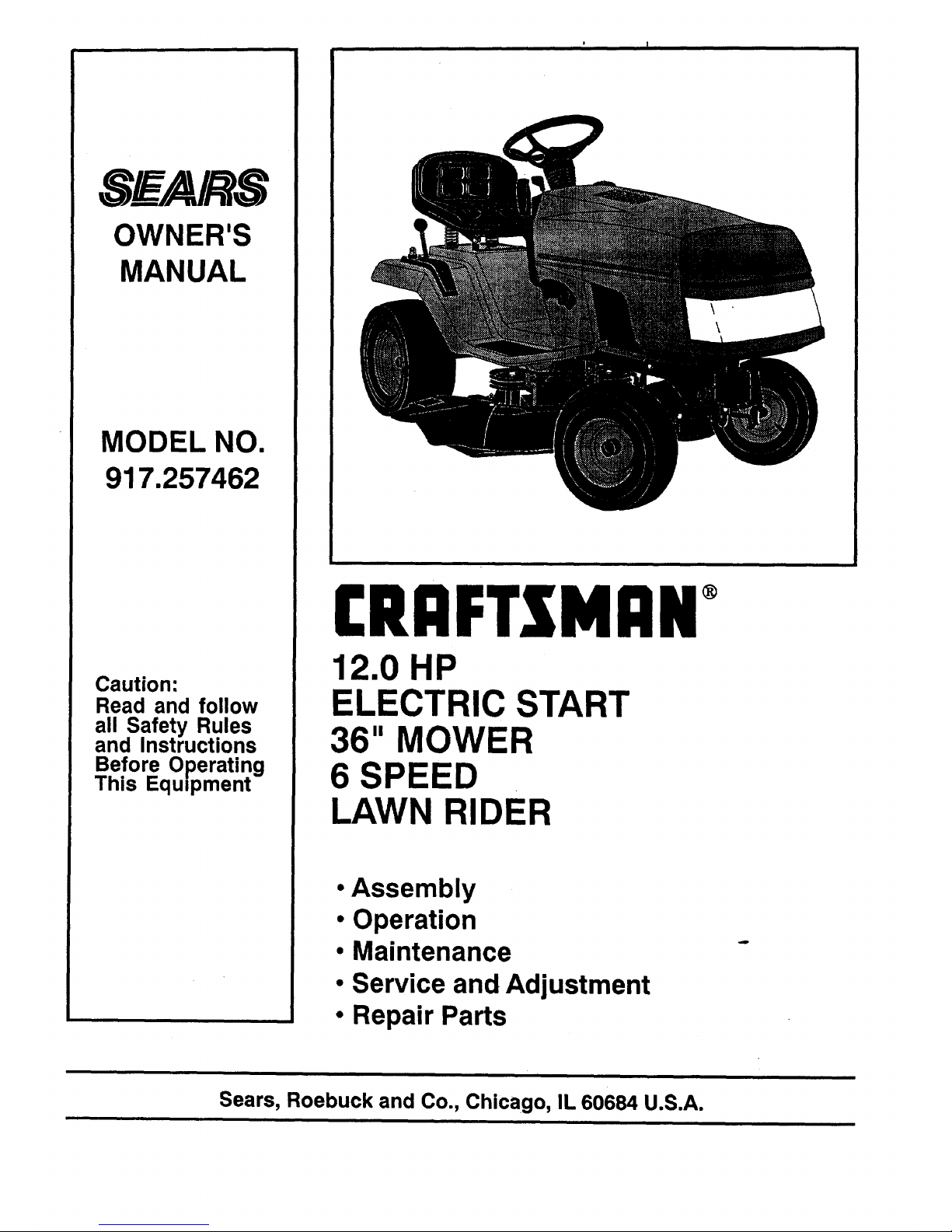
[RRFTSMRN
12.0 HP
ELECTRIC START
36" MOWER
6 SPEED
LAWN RIDER
• Assembly
• Operation
• Maintenance
• Service and Adjustment
• Repair Parts
Sears, Roebuck and Co., Chicago, IL 60684 U.S.A.
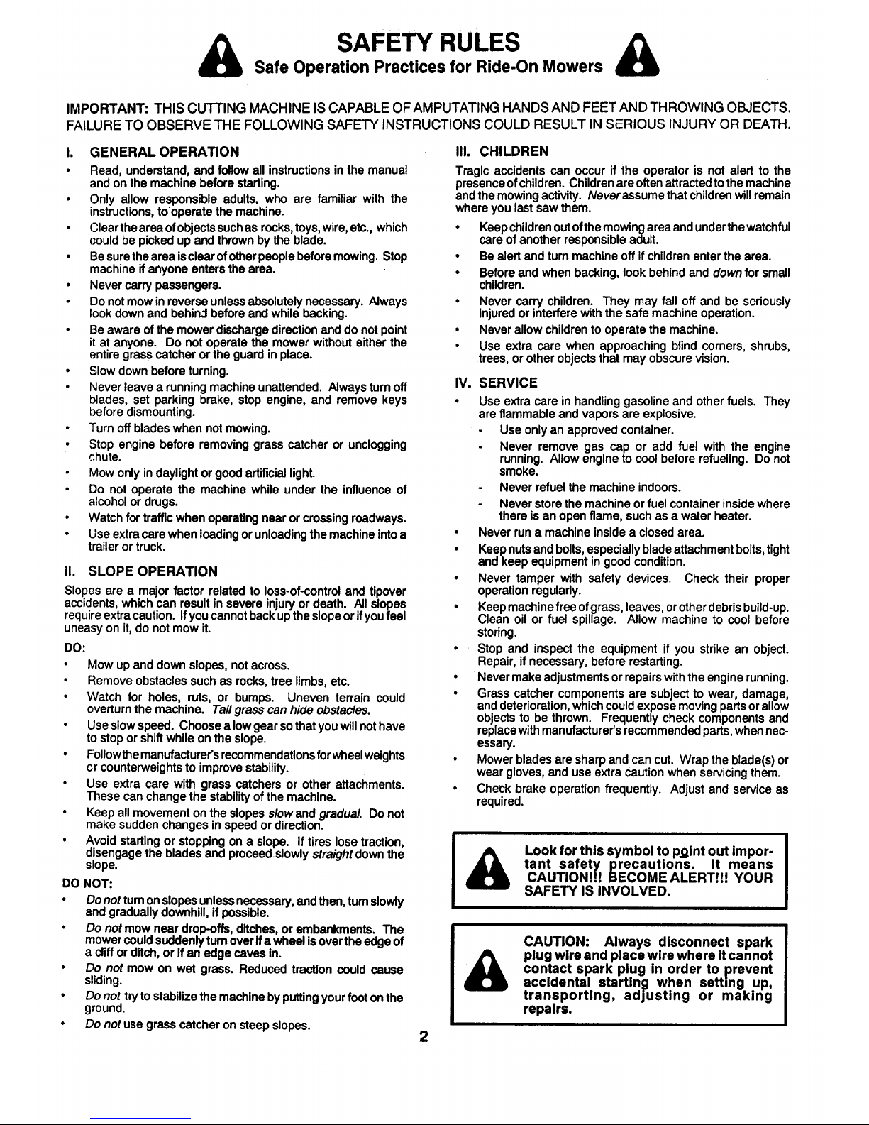
& SAFETY RULES &
Safe Operation Practices for Ride-On Mowers
IMPORTANT: THIS CUTTING MACHINE IS CAPABLE OFAMPUTATING HANDS AND FEET AND THROWING OBJECTS.
FAILURE TO OBSERVE THE FOLLOWING SAFETY INSTRUCTIONS COULD RESULT IN SERIOUS INJURY OR DEATH.
I. GENERAL OPERATION
• Read, understand, and follow all instructions in the manual
and on the machine before starting.
• Only allow responsible adults, who are familiar with the
instructions, to operate the machine.
• Clear the area of objectssuch as rocks, toys, wire, etc., which
could be picked up and thrown by the blade.
• Be sure the area isclear of other people before mowing. Stop
machine if anyone enters the area.
• Never carry passengers.
• Do not mow in reverse unless absolutely necessary. Always
look down and behin:l before and while backing.
• Be aware of the mower discharge direction and do not point
it at anyone. Do not operate the mower without either the
entire grass catcher or the guard in place.
• Slow down before turning.
• Never leave a running machine unattended. Always turn off
blades, set parking brake, stop engine, and remove keys
before dismounting.
• Turn off blades when not mowing.
• Stop engine before removing grass catcher or unclogging
chute.
• Mow only in daylight or good artificial light.
• Do not operate the machine while under the influence of
alcohol or drugs.
• Watch for traffic when operating near or crossing roadways.
• Use extra care when loading or unloading the machine intoa
trailer or truck.
II. SLOPE OPERATION
Slopesare a majorfactor related to loss-of-controland tipover
accidents,whichcanresultin severeinjuryordeath. All slopes
requireextracaution.Ifyoucannotbackuptheslopeorifyoufeel
uneasyon it,do notmowit.
DO:
• Mow upand downslopes,notacross.
• Removeobstaclessuchas rocks,tree limbs,etc.
• Watch for holes, ruts, or bumps. Uneven terrain could
overturn the machine. Tallgrasscan hide obstacles.
• Useslowspeed. Choosea lowgearsothatyouwillnothave
to stopor shiftwhileonthe slope.
• Followthemanufacturer'srecommendationsforwheelweights
or counterweightsto improvestability.
• Use extra care with grass catchersor other attachments.
These can changethe stabilityofthemachine.
• Keepall movementontheslopesslowand gradual. Donot
make suddenchangesinspeed ordirection.
• Avoidstartingor stoppingon a slope. If tireslosetraction,
disengagethebladesandproceedslowlystraightdownthe
slope.
DO NOT:
• Donot tumonslopesunlessnecessary,and then, tumslowly
aria graouallydownhill,If possible.
• Do notmowneardrop-offs,ditches,orembankments.The
mowercould suddenlyturnoverifa wheel isoverthe edgeof
a clifforditch,or ifan edge cavesin.
• Do not mow on wet grass. Reduced tractioncould cause
sliding.
• Do not trytostabilizethemachinebyputtingyourfootonthe
ground.
• Do notusegrasscatcheron steepslopes.
III. CHILDREN
Tragic accidentscan occur if the operatoris not alert to the
presenceof children.Childrenareoftenattractedto themachine
andthemowingactivity.Neverassumethatchildrenwillremain
whereyoulast sawthem.
• Keepchildrenoutofthemowingareaandunderthewatchful
care of anotherresponsibleadult.
• Be alertand turnmachineoff if childrenenterthe area.
• Beforeand when backing,lookbehindand downfor small
children.
• Never carry children. They may fall off and be seriously
Injuredorinterferewiththe safe machineoperation.
• Neverallowchildrento operatethe machine.
• Use extracare when approachingblindcorners,shrubs,
trees, orotherobjectsthatmay obscurevision.
IV. SERVICE
• Use extra care in handling gasoline and other fuels. They
are flammable and vapors are explosive.
Use only an approved container.
Never remove gas cap or add fuel with the engine
running. Allow engine to cool before refueling. Do not
smoke.
Never refuel the machine indoors.
Never store the machine or fuel container inside where
there is an open flame, such as a water heater.
• Never run a machine inside a closed area.
• Keep nuts and bolts, especially blade attachment bolts, tight
and keep equipment in good condition.
• Never tamper with safety devices. Check their proper
operation regularly.
• Keep machine free of grass, leaves, orother debris build-up.
Clean oil or fuel spillage. Allow machine to cool before
storing.
• Stop and inspect the equipment if you strike an object.
Repair, if necessary, before restarting.
• Never make adjustments or repairs with the engine running.
• Grass catcher components are subject to wear, damage,
and deterioration, which could expose moving parts or allow
objects to be thrown. Frequently check components and
replace with manufacturer's recommended parts, when nec-
essary.
• Mower blades are sharp and can cut. Wrap the blade(s) or
wear gloves, and use extra caution when servicing them.
• Check brake operation frequently. Adjust and service as
required.
Look for this symbol to p.gint out Impor-
tant safety precautions. It means
CAUTION!!! BECOME ALERT!!! YOUR
SAFETY IS INVOLVED.
2
CAUTION: Always disconnect spark
plug wire and place wire where itcannot
contact spark plug in order to prevent
accidental starting when setting up,
transporting, adjusting or making
repairs.

CONGRATULATIONSon your purchaseof a Sears
LawnRider. It has beendesigned,engineeredand
manufacturedto giveyouthebestpossibledependability
andperformance.
Shouldyouexperience any problem you cannot easily
remedy, please contact your nearest Sears Service
Center/Department. We have competent, well-trained
technicians and the proper tools to service or repair this
unit.
Please read and retain this manual. The instructions will
enable you to assemble and maintain your unit properly,
Always observe the "SAFETY RULES".
MODEL
NUMBER 917.257462
SERIAL
NUMBER
DATE OF PURCHASE
THE MODELAND SERIAL NUMBERS WILL BE FOUND
ON A PLATE UNDER THE SEAT.
YOU SHOULD RECORD BOTH SERIAL NUMBER AND
DATE OF PURCHASE AND KEEP IN A SAFE PLACE
FOR FUTURE REFERENCE.
MAINTENANCE AGREEMENT
A Sears Maintenance Agreement isavailable onthis prod-
uct. Contact your nearest Sears store for details.
CUSTOMER RESPONSIBILITIES
• Read and observe the safety rules.
• Follow a regular schedule inmaintaining, caringfor and
using your unit.
• Follow the instructions under "Maintenance" and
"Storage" sections of this owner's manual.
PRODUCT SPECIFICATIONS
HORSEPOWER: 12.0
GASOLINECAPACITY: 1.4 GALLONS
UNLEADED REGULAR
OIL (3.0PINTS) SAE 30 (or10W-30)
WINTER: SAE 5W-30
SPARK PLUG(GAP.030 IN.): CHAMPION RJ-19LM
STD361458
VALVECLEARANCE: INTAKE.005 - .007 IN.
EXHAUST .009 - .011 IN.
GROUND SPEED: FORWARD
1st " .95 MPH
2nd 1.25 MPH
3rd 1.94 MPH
4th 2.91 MPH
5th 3.71 MPH
6th 4.76 MPH
REVERSE: 1.46 MPH
TIRE PRESSURE: FRONT: 14 PSI
REAR: 12 PSI
CHARGING SYSTEM: 3 AMPS BA'I-FERY
@3600 RPM
BLADE BOLT TORQUE: 30-35 FT. LBS.
WARNING: This unit is equipped with an internal combus-
tion engine and should not be used on or near any unim-
proved forest-covered, brush-covered or grass-covered
land unless the engine's exhaust system is equipped with
a spark arrester meeting applicable local or state laws (if
any). If a spark arrester is used, it should be maintained in
effective working order by the operator.
In the state of California the above is required by law
(_Section4442 of the California Public Resources Code).
Other states may have similar laws. Federal laws apply on
federal lands. A spark arrester for the muffler is available
through your nearest Sears Authorized Service Center
(See REPAIR PARTS section of this manual).
LIMITED TWO YEAR WARRANTY ON ELECTRIC START RIDING EQUIPMENT
For two years from date of purchase,when this ridingequipmentis maintained,lubricated,and tuned up accordingto the
operating and maintenanceinstructionsin the owner's manual, Sears will repair free of charge any defect in materialor
workmanship.
ThisWarrantydoesnot cover:
• Tirereplacementorrepaircausedby puncturesfrom outsideobjects(suchas nails,thorns,stumps,or glass).
• Expendableitemswhichbecomewornduringnormaluse,suchas blades,sparkplug,aircleanersandbelts.
• Repairsnecessarybecause of operatorabuse or negligence,includingbent crankshaftsand the failureto maintainthe
equipmentaccording totheinsttuctionscontainedinthe owner'smanual.
• Ridingequipmentusedfor commercialorrentalpurposes.
FULL 90 DAY WARRANTY ON BATTERY
For90 daysfrom dateof purchase,if any batte_ includedwiththisridingequipmentprovesdefectiveinmaterialorworkmanship
andourtestingdeterminesthe batterywillnotholda charge,Searswillreplacethepatten] at nocharge.
WARRANTY SERVICE IS AVAILABLEBY CONTACTINGTHE NEARESTSEARS SERVICECENTER/DEPARTMENT IN THE
UNITEDSTATES. THIS WARRANTYAPPLIESONLYWHILE THIS PRODUCT IS IN USEIN THE UNITEDSTATES.
This Warrantygivesyouspecificlegalrights,and youmayalsohaveotherrightswhichvaryfrom stateto state.
SEARS, ROEBUCK AND CO., D/731CR-W SEARS TOWER, CHICAGO, IL 60684
3

i •
ACCESSORIES AND ATTACHMENTS
Theseaccessoriesand attachmentswereavailablewhenthe unitwas purchased. They are alsoavailableat mostSears retailoutlets,
catalcgandservicecenters. MostSears storescan ordertheseitemsfor youwhenyouprovidethe modelnumberof yourtractor.
ENGINE
SPARKPLUG MUFFLER AIR FILTER STABILIZER
MAINTENANCE
BLADES BELTS
PERFORMANCE
Searsoffersa widevarietyofattachmentsthatfityourvehicle. Manyofthese are listedbelowwithbriefexplanationsofhowtheycanhelp
you Thislistwascurrent_tthetimeofpublication;however,itmaychangeinfutureyears-moreattachmentsmaybeadded,changesmay
bemadeintheseattachments,orsomemaynolongerbeavailableorfityourmodel.Contact your nearestSears storefor theaccessories
and attachments that are available for your unit.
Mostof these attachmentsdo notrequireadditionalhitchesorconversionkits(thosethat do are indicated)and are designedfor easy
attachinganddetaching.
PERMANEX BAGGER lets you collect grass clippingsand
leaves for a healthier,neater lookinglawn. Two Permanex
containershold30-gallonplasticbags.
LAWN SWEEPERS letyou collectgrassclippingsandleaves.
CARTS make haulingeasy. Varietyofsizesavailable.
ROLLER for smootherlawn surface. 36-inch wide, 18-inch
diameterwater-tightdrumholdsupto390 Ibs.ofweight.Rounded
edgespreventharm to turf. Adjustablescraperautomatically
cleansdrum.
SPREADER/SEEDERS make seeding, fertilizing,and weed
killingeasy. Broadcastspreadersare also usefulfor granular
de-icersandsand.
CORING AERATOR takes smallplugsoutofsoilto allowmois-
ture and nutrientsto reach grass roots. 36-inch swath. 24
hardenedsteelcoringtips. 150 lb. capacityweighttray.
AERATOR promotesdeep root growthfor a healthylawn.Ta.
pered2o5-inchsteel spikesmountedon 10-inchdiameterdiscs
punctureholesin soilat closeintervalstolet moisturesoakin.
Steelweighttray forincreasedpenetration.
MULCH RAKE/DETHATCHER loosenssoilandflipsthatchand
mattedleavestolawnsurfaceforeasypickup.Twentyspringtine
teeth. Usefultopreparebareareasfor seeding. Availableforrear
mountingonly.
SPRAYERS use 12-volt DC electricmotorthatconnectsto the
tractor battery or other 12-volt source. Includes booms for
automaticsprayingwhen pulling,and hand held wandfor spot
spraying. Wand has adjustablespray pattern. For applying
herbicides,insecticides,fungicides,and liquidfertilizers.
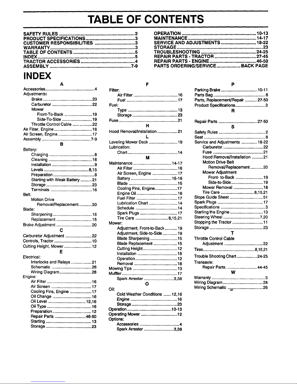
TABLE OF CONTENTS
SAFETY RULES ............................................................ 2
PRODUCT SPECIFICATIONS ....................................... 3
CUSTOMER RESPONSIBILITIES ................................ 3
WARRANTY ................................................................... 3
TABLE OF CONTENTS ................................................. 5
INDEX ............................................................................. 5
TRACTOR ACCESSORIES ........................................... 4
ASSEMBLY ................................................................ 7-9
OPERATION ........................................................... 10-13
MAINTENANCE ...................................................... 14-17
SERVICE AND ADJUSTMENTS ............................ 18-22
STORAGE .................................................................... 23
TROUBLESHOOTING ............................................ 24-25
REPAIR PARTS - TRACTOR ................................. 27-45
REPAIR PARTS - ENGINE ..................................... 46-50
PARTS ORDERING/SERVICE ................... BACK PAGE
INDEX
A
Accessories............................................4
Adjustments:
Brake...........................................20
Carburetor...................................22
Mower
Front-To-Back........................19
Side-To-Side ..........................19
ThrottleControlCable .................22
AirFilter,Engine................................. 16
AirScreen,Engine..............................17
Assembly...........................................7-9
B
Battery:
Charging........................................8
Cleaning...................................... 16
Installation.....................................9
Levels ....................................... 8,15
Preparation....................................8
StartingwithWeak Battery..........21
Storage........................................23
Terminals ....................................16
Belt:
MotionDrive
Removal/Replacement...........20
Blade:
Sharpening..................................15
Replacement...............................15
BrakeAdjustment...............................20
c
Carburetor Adjustment .......................22
Controls, Tractor ................................. 10
Cutting Height, Mower........................ 12
E
Electrical:
Interlocks and Relays ..................21
Schematic ...................................26
Wiring Diagram ............................28
Engine:
Air Filter .......................................16
Air Screen ...................................17
Cooling Fins, Engine...................17
Oil Change ..................................16
Oil Level ................................. 12,16
Oil Type ....................................... 16
Preparation..................................12
Repair Parts ...........................46-50
Starting ........................................ 13
Storage......................................_23
F
Filter:
AirFilter.......................................16
Fuel .............................................17
Fuel:
Type ............................................13
Storage........................................23
Fuse....................................................21
H
Hood Removal/Installation..................21
L
LevelingMowerDeck.........................19
Lubrication:
Chart............................................14
M
Maintenance..................................14-17
AirFilter.......................................16
AirScreen,Engine...................... 17
Battery....................................15-16
Blade...........................................15
CoolingFins,Engine....................17
EngineOil....................................16
FuelFilter....................................17
LubricationChart.........................14
Schedule.....................................14
SparkPlugs.................................17
TireCare .............................8,15,21
Mower:
Adjustment,Front-to-Back...........19
Adjustment,Side-to-Side.............19
BladeSharpening........................15
BladeReplacement.....................15
CuttingHeight..............................12
Installation...................................18
Operation.....................................12
Removal......................................18
MowingTips .......................................13
Muffler.................................................17
SparkArrester..........................3,38
O
Oil:
ColdWeather Conditions.......12,16
Engine.........................................16
Storage........................................23
Operation.......................................10-13
OperatingMower................................12
Options:
Accessories...................................4
SparkArrester..........................3,38
P
ParkingBrake................................ 10-11
PartsBag..............................................6
Parts,Replacement/Repair...........27-50
ProductSpecifications...........................3
R
RepairParts..................................27-50
S
Safety Rules.........................................2
Seat ...................................................... 8
Service andAdjustments..............18-22
Carburetor...................................22
Fuse ............................................21
HoodRemoval/Installation..........21
MotionDrive Belt
Removal/Replacement...........20
MowerAdjustment
Front-to-Back ........................19
Side-to-Side............................19
MowerRemoval..........................18
TireCare .............................8,15,21
SlopeGuideSheet .............................51
SparkPlugs........................................17
Specifications.......................................3
Startingthe Engine.............................13
SteeringWheel................................7,20
StoppingtheTractor........................... 11
Storage...............................................23
T
ThrottleControlCable
Adjustment..................................22
Tires...................................................8,15,21
TroubleShootingChart..................24-25
Transaxle:
RepairParts........................... 44-45
W
Warranty...............................................3
WiringDiagram...................................28
WiringSchematic....,,;..........................26
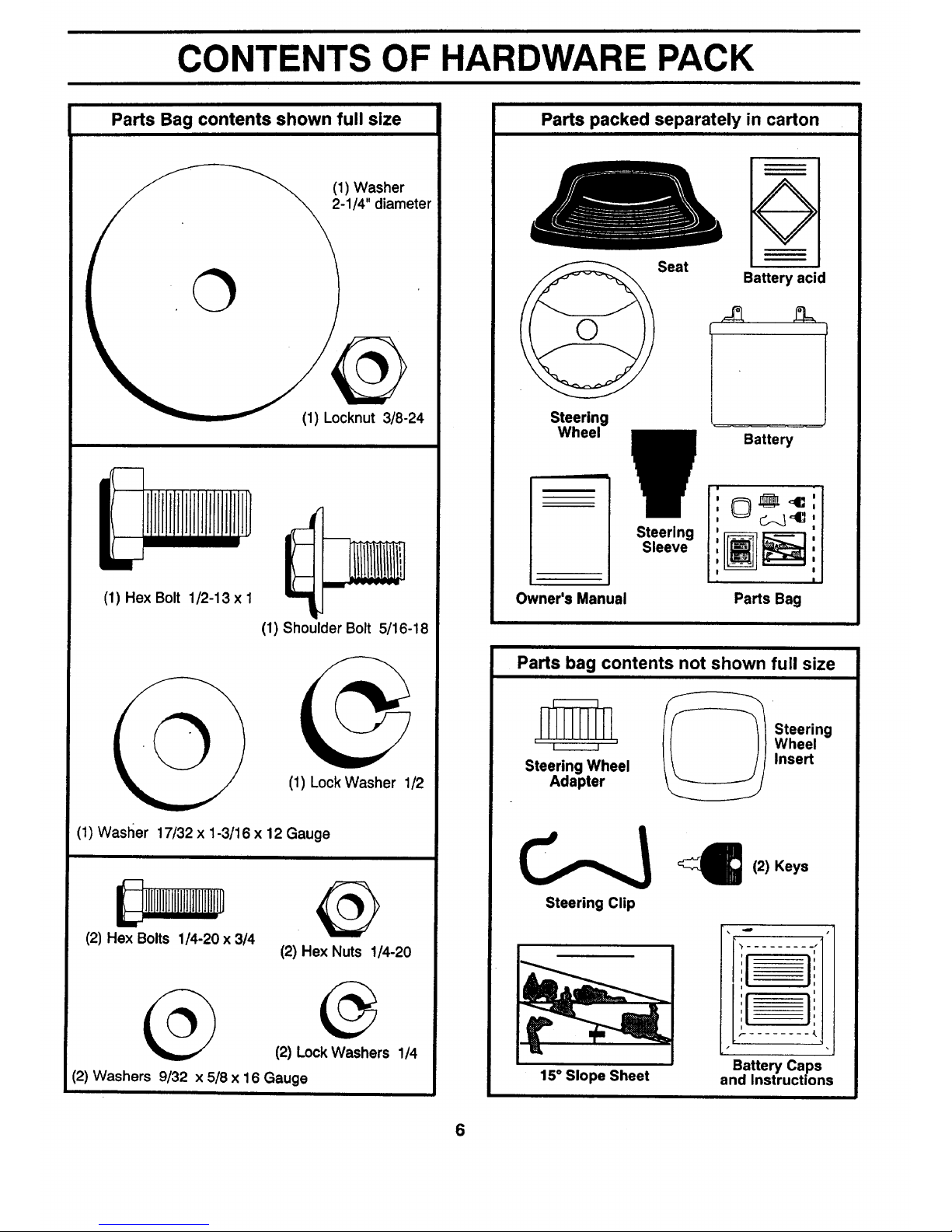
CONTENTS OF HARDWARE PACK
Parts Bag contents shown full size
(1) Washer
2-1/4" diameter
(1) Locknut 3/8-24
(1) Hex Bolt 1/2-13 x I
(1) Shoulder Bolt 5/16-18
(1) Lock Washer 1/2
(1) Wasller 17/32 x 1-3/16 x 12 Gauge
111II llllllll_
(2) Hex Bolts 1/4-20 x 3/4
(2) Hex Nuts 1/4-20
(2) Lock Washers 1/4
(2) Washers 9/32 x 5/8 x 16 Gauge
Parts packed separately in carton
Steering
Wheel
Owner's Manual
Seat
Battery acid
f I
V Battery
• ,, c-._ ,,
,
I I
! I
Parts Bag
Parts bag contents not shown full size
_ Steering
' , , ' Wheel
Steering Wheel Insert
Adapter
Steering Clip
(2) Keys
i
f-
15° Slope Sheet
Battery Caps
and Instructions
6
ASSEMBLY
TOOLS REQUIRED FOR ASSEMBLY
A socketwrench set will make assembly easier. Standard
wrench sizes are listed.
(1) 9/16" wrench
(2) 7/16" wrenches
(1) 1/2" wrench
(1) 3/4" wrench
Pliers
Tire pressure gauge
Screwdriver
Utility knife
When right and left hand is mentioned in this manual, it
means when you are in the operating position (seated
behind the steering wheel).
TO REMOVE UNIT FROM CARTON
UNPACK CARTON
• Remove all accessible loose parts and parts cartons
from carton (See page 6).
• Cut along dotted lines onthe carton, from top tobottom,
all four corners of carton and lay panels fiat.
• Check for any additional loose parts or cartons and
remove.
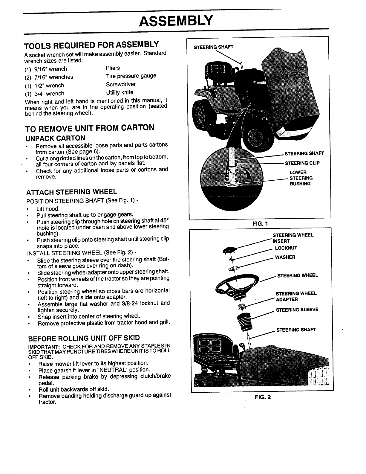
ATTACH STEERING WHEEL
POSITION STEERING SHAFT (See Fig. 1) -
• Lift hood.
• Pull steering shaft up to engage gears.
• Push steering clip through hole on steering shaft at 45°
(hole is located under dash and above lower steering
bushing).
• Push steering clip onto steering shaft until steering clip
snaps into place.
INSTALL STEERING WHEEL (See Fig. 2) -
• Slide the steering sleeve over the steering shaft (Bot-
tom of sleeve goes over ring on dash).
• Slidesteering wheel adapter onto uppersteering shaft.
• Position front wheels of the tractor sothey are pointing
straight forward.
• Position steering wheel so cross bars are horizontal
(left to right) andslide onto adapter.
• Assemble large flat washer and 3/8-24 Iocknut and
tighten securely.
• Snap insert into center of steering wheel.
• Remove protective plastic from tractor hood and grill.
BEFORE ROLLING UNIT OFF SKID
IMPORTANT: CHECK FOR AND REMOVEANY STAPLES IN
SKIDTHATMAYPUNCTURETIRESWHEREUNITIS TO ROLL
OFF SKID.
• Raise mower lift lever to its highest position.
• Place gearshift lever in "NEUTRAL" position.
• Release parking brake by depressing clutch/brake
pedal.
• Roll unit backwards off skid.
• Remove banding holding discharge guard up against
tractor.
STEERING SHAFT
;TEERING SHAFT
STEERING CLIP
LOWER
BUSHING
FIG. 1
STEERING WHEEL
INSERT
LOCKNUT
WASHER
_STEERING WHEEL
STEERING WHEEL
STEERING SLEEVE
STEERING SHAFT
FIG. 2
i _ ii I "_ i I fill I Ill"
ASSEMBLY
HOW TO SET UP YOUR TRACTOR
PREPARE BATTERY (See Fig. 3)
CAUTION: Wear eye and face shield.
Wash hands or clothing immediately if
accidentally in contact with battery acid.
Do not smoke. Fumes from charged
battery acid are explosive.
Read the instructions included with the
battery vent caps. Always wear gloves,
clothing and goggles to protect your
hands, skin and eyes.
Your unit has a battery charging system which is sufficient
for normal use. However, periodic charging ofthe battery
with an automotive charger will extend its life.
• See instructions packed with vent caps in parts bag.
• Fill battery with acid. Filleach cell until it reaches the
bottom of the vent wells. Do not overfill.
• Allow battery to stand and settle for at least thirty
minutes. After standing, check the level of acid. If
below the vent wells, add more acid until the correct
level is reached.
While battery is standing (after adding acid) and later,while
battery is being charged, continue with assembly of unit.
IMPORTANT: TO MAXIMIZE THE LIFE OFYOUR BATTERY,
IT IS NECESSARY THAT THE BATTERY BE CHARGED
BEFOREUSE. FAILURETO CHARGEBATTERYCANRESULT
INA SHORTENED BATTERYLIFE.
• Charge battery at a rate of 6 amperes for 1 hour. Use
a 12 volt battery charger. Observe all safety precau-
tions required for battery charging.
• Check the acid level after the battery is charged. Ifthe
acid has fallen below the correct level, add distilled or
ironfree water.
• Install the vent caps to cover the vent wells. Wash the
top of the battery with water to remove any acid, then
wipe dry.
• Check battery case for leakage to make sure that no
damage has occurred in handling.
• Dispose of excess battery acid. Neutralize acid for
disposal by adding it to four inches of water in a five
gallon plastic container. Stir with a wooden or plastic
paddle while adding baking soda until the addition of
more soda causes no more foaming.
• Follow instructions on how to install battery.
CUT AWAY VIEW
VENT CAP
BATTERY
CELL ACID
LEVEL
FIG. 3
8
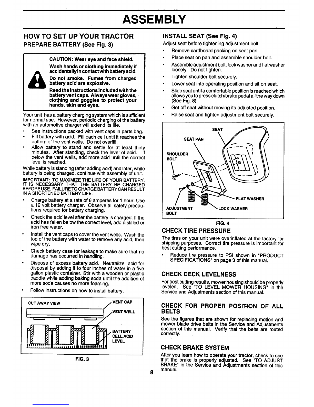
INSTALL SEAT (See Fig. 4)
Adjust seat before tightening adjustment bolt.
• Remove cardboard packing on seat pan.
• Place seat on pan and assemble shoulder bolt.
• Assemble adjustment bolt, Iockwasher and flat washer
loosely. Do not tighten.
• Tighten shoulder bolt securely.
• Lower seat into operating position and sit on seat.
• Slide seat untila comfortable position is reached which
allowsyou to press clutch/brake pedal alltheway down
(See Fig. 8).
• Get off seat without moving its adjusted position.
• Raise seat and tighten adjustment bolt securely.
SEAT
SEAT PAN
SHOULDER
BOLT
- FLAT WASHER
ADJUSTMENT
BOLT
,LOCK WASHER
FIG. 4
CHECKTIRE PRESSURE
The tires on your unit were overinflated at the factory for
shipping purposes. Correct tire pressure is important for
best cutting performance.
• Reduce tire pressure to PSI shown in "PRODUCT
SPECIFICATIONS" on page 3 of this manual.
CHECK DECK LEVELNESS
For best cuttingresults, mower housing shouldbe properly
leveled. See "TO LEVEL MOWER HOUSING" in the
Service and Adjustments section of this manual.
CHECK FOR PROPER POSIT-ION OF ALL
BELTS
See the figures that are shown for replacing motion and
mower blade drive belts in the Service and Adjustments
section of this manual. Verify that the belts are routed
correctly.
CHECK BRAKE SYSTEM
After you learn how to operate your tractor, check to see
that the, brake is properly adjusted. See "TO ADJUST
BRAKE' in the Service and Adjustments section of this
manual.
i i i I ill " I i ill " If It
ASSEMBLY
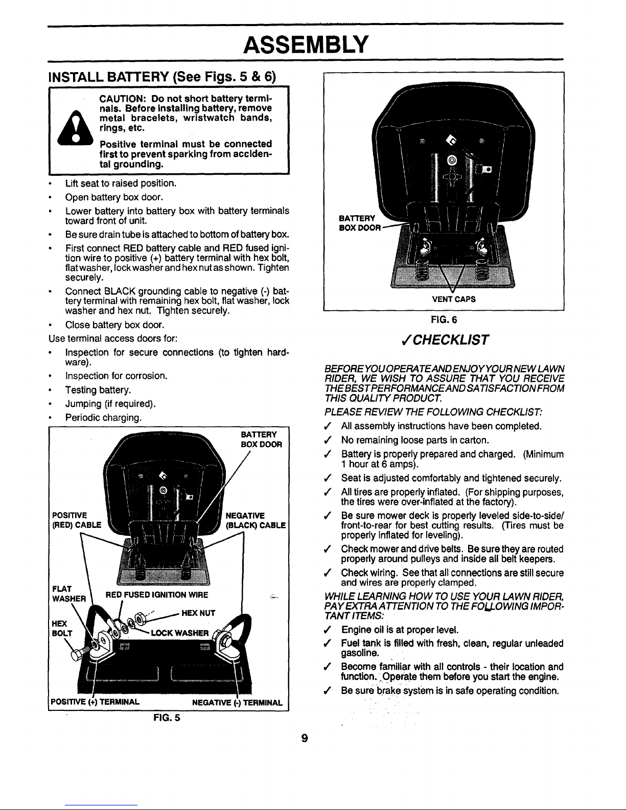
INSTALL BATTERY (See Figs. 5 & 6)
CAUTION: Do not short battery termi-
nals. Before Installing battery, remove
metal bracelets, wristwatch bands,
rings, etc.
Positive terminal must be connected
first to prevent sparking from acciden-
tal grounding.
Lift seat to raised position.
• Open battery box door.
• Lower battery into battery box with battery terminals
toward front of unit.
• Be sure drain tube is attached to bottom of battery box.
• First connect RED battery cable and RED fused igni-
tion wire to positive (+) battery terminal with hex bolt,
flat washer, lock washer and hex nut as shown. Tighten
securely.
• Connect BLACK grounding cable to negative (-) bat-
tery terminal with remaining hex bolt, flat washer, lock
washer and hex nut. Tighten securely.
• Close battery box door.
Use terminal access doors for:
• Inspection for secure connections (to tighten hard-
ware).
• Inspection for corrosion.
• Testing battery.
• Jumping (if required).
• Periodic charging.
BATTERY
BOX DOOR
POSITIVE NEGATIVE
(RED)CABLE (BLACK) CABLE
FLAT
WASHER
POSITIVE (+) TERMINAL NEGATIVE (-) TERMINAL
FIG. 5
BATTERY
VENT CAPS
FIG. 6
,/CHECKLIST
BEFORE YOU OPERA TEAND ENJOY YOUR NEW LAWN
RIDER, WE WISH TO ASSURE THAT YOU RECEIVE
THE BEST PERFORMANCEAND SA TISFACTION FROM
THIS QUALITY PRODUCT.
PLEASE REVIEW THE FOLLOWING CHECKLIST."
,/ All assembly instructionshave been completed.
,/ No remaining loose parts in carton.
,/ Battery is properly prepared and charged. (Minimum
1 hour at 6 amps).
#" Seat is adjusted comfortably and tightened securely.
,/ All tires are properly inflated. (For shipping purposes,
the tires were over-inflated at the factory).
/ Be sure mower deck is properly leveled side-to-side/
front-to-rear for best cutting results. (Tires must be
properly inflated for leveling).
,/ Check mower and drive belts. Be sure they are routed
properly around pulleys and inside all belt keepers.
,/' Check wiring. See that all connections are still secure
and wires are properly clamped.
WHILE LEARNING HOW TO USE YOUR LAWN RIDER,
PAY EXTRA A TTENTION TO THE FOLLOWING IMPOR-
TANT ITEMS:
/ Engine oil is at proper level.
/ Fuel tank is filled with fresh, clean, regular unleaded
gasoline.
,/ Become far_iliar with all controls - their location and
function: i.OPerate them before you start the engine.
,/ Be sure brake system is in safe operating condition.
9
OPERATION
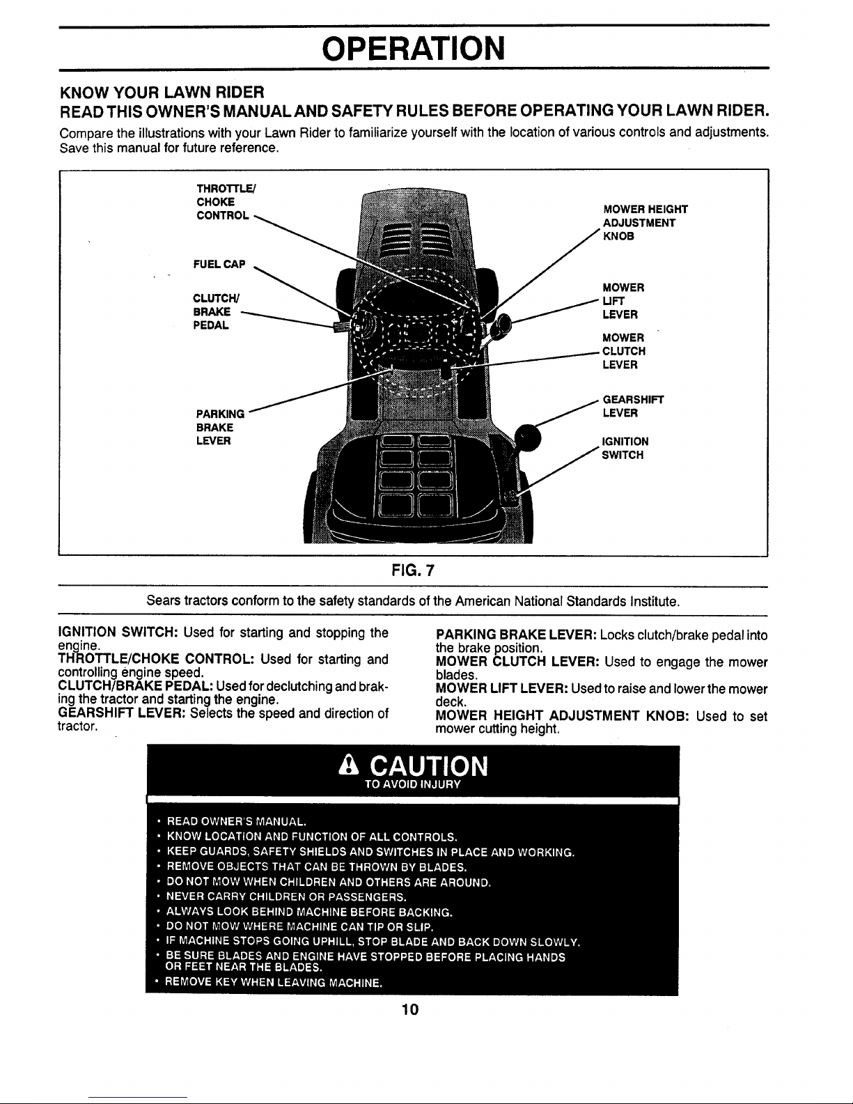
KNOW YOUR LAWN RIDER
READ THIS OWNER'S MANUAL AND SAFETY RULES BEFORE OPERATING YOUR LAWN RIDER.
Compare the illustrations with your Lawn Rider to familiarize yourself with the location of various controls and adjustments.
Save this manual for future reference.
THROTrLE/
CHOKE
CONTROL
FUEL CAP
MOWER HEIGHT
ADJUSTMENT
KNOB
MOWER
CLUTCH/ UFT
BRAKE LEVER
PEDAL
MOWER
CLUTCH
LEVER
PARKING
BRAKE
LEVER
GEARSHIFT
LEVER
IGNITION
FIG. 7
Searstractorsconformto the safetystandardsofthe AmericanNationalStandardsInstitute.
IGNITION SWITCH: Used for starting and stopping the
engine.
THROTTLE/CHOKE CONTROL: Used for starting and
controllingengine speed.
CLUTCH/BRAKE PEDAL: Used for declutchingand brak-
ingthe tractor and starting the engine.
GEARSHIFT LEVER: Selects the speed and direction of
tractor.
10
PARKING BRAKE LEVER: Locks clutch/brake pedal into
the brake position.
MOWER CLUTCH LEVER: Used to engage the mower
blades.
MOWER LIFT LEVER: Used to raise and lower the mower
deck.
MOWER HEIGHT ADJUSTMENT KNOB: Used to set
mower cutting height.
OPERATION
i
The operation of any tractor can result in foreign objects thrown into the eyes, which can result
in severe eye damage. Always wear safety glasses or eye shields before starting your tractor
and while moving. We recommend Wide Vision Safety Mask for over the spectacles or standard
safety glasses.
HOW TO USE YOUR TRACTOR
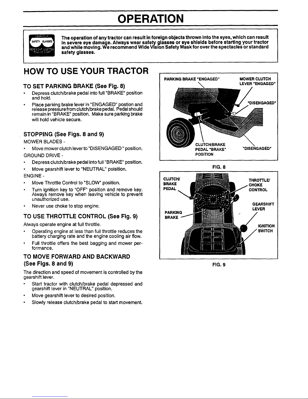
TO SET PARKING BRAKE (See Fig. 8)
• Depress clutch/brake pedal intofull "BRAKE" position
and hold.
Place parking brake lever in "ENGAGED" postion and
release pressure from clutch/brake pedal. Pedal should
remain in "BRAKE" position. Make sure parking brake
will hold vehicle secure.
STOPPING (See Figs. 8 and 9)
MOWER BLADES -
• Move mower clutch lever to "DISENGAGED" position.
GROUND DRIVE -
• Depress clutch/brake pedal into full "BRAKE" position.
• Move gearshift lever to "NEUTRAL" poisition.
ENGINE -
• Move Throttle Control to "SLOW" position.
• Turn ignition key to "OFF" position and remove key.
Always remove key when leaving vehicle to prevent
unauthorized use.
• Never use choke to stop engine.
TO USE THROTTLE CONTROL (See Fig. 9)
Always operate engine at full throttle.
• Operating engine at less than full throttle reduces the
battery charging rate and the engine cooling air flow.
• Full throttle offers the best bagging and mower per-
formance.
TO MOVE FORWARD AND BACKWARD
(See Figs. 8 and 9)
The direction and speed of movement is controlled by the
gearshift lever.
• Start tractor with clutch/brake pedal depressed and
gearshift lever in "NEUTRAL" position.
• Move gearshift lever to desired position.
• Slowly release clutch/brake pedal to start movement.
PARKING BRAKE "ENGAGED" MOWER CLUTCH
LEVER "ENGAGED"
SENGAGED"
_CLUTCH/BRAKE \
PEDAL "BRAKE" "DISENGAGED"
POSITION
FIG. 8
CLUTCW THROTTL_
BRAKE CHOKE
PEDAL CONTROL
PARKING
BRAKE
GEARSHIFT
LEVER
IGNITION
FIG. 9
OPERATION
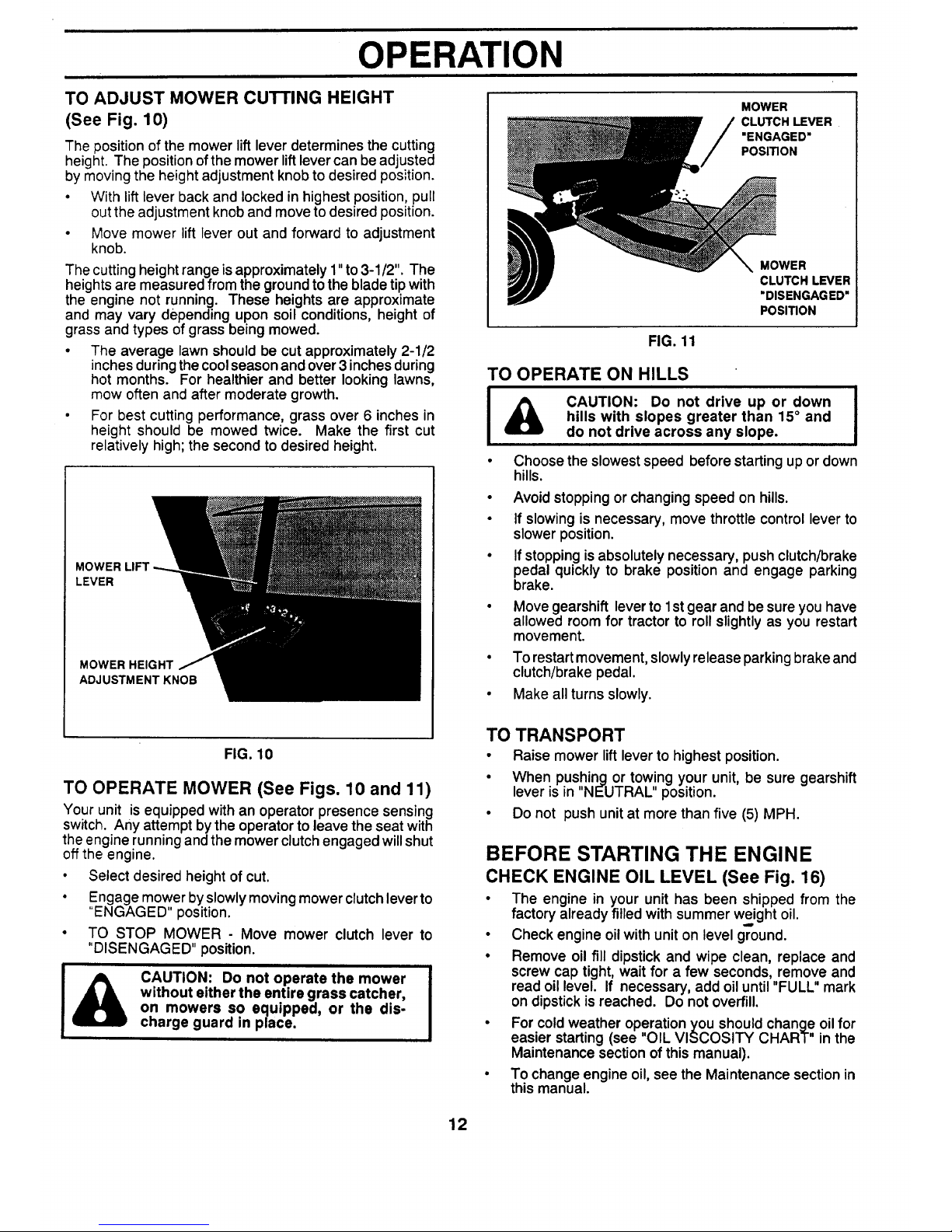
TO ADJUST MOWER CUTTING HEIGHT
(See Fig. 10)
The position of the mower lift lever determines the cutting
height. The position of the mower lift lever can be adjusted
by moving the height adjustment knob to desired position.
• With lift lever back and locked in highest position, pull
out the adjustment knob and move to desired position.
• Move mower lift lever out and forward to adjustment
knob.
The cutting height range is approximately 1" to 3-1/2". The
heights are measured from the ground to the blade tip with
the engine not running. These heights are approximate
and may vary depending upon soil conditions, height of
grass and types of grass being mowed.
• The average lawn should be cut approximately 2-1/2
inches during the cool season and over 3 inches during
hot months. For healthier and better looking lawns,
mow often and after moderate growth.
• For best cutting performance, grass over 6 inches in
height should be mowed twice. Make the first cut
relatively high; the second to desired height.
MOWER LIFT
LEVER
MOWER HEIGHT
ADJUSTMENT KNOB
FIG. 10
TO OPERATE MOWER (See Figs. 10 and 11)
Your unit is equipped with an operator presence sensing
switch. Any attempt bythe operator to leave the seat with
the engine running and the mower clutch engaged will shut
offthe engine.
• Select desired height of cut.
• Engage mower byslowly moving mower clutchlever to
"ENGAGED" position.
• TO STOP MOWER - Move mower clutch lever to
"DISENGAGED" position.
CAUTION: Do not operate the mower
without either the entire grass catcher,
on mowers so equipped, or the dis-
charge guard in place.
MOWER
CLUTCH LEVER
"ENGAGED"
POSITION
MOWER
CLUTCH LEVER
"DISENGAGED"
POSITION
FIG. 11
TO OPERATE ON HILLS
CAUTION: Do not drive up or down
hills with slopes greater than 15° and
do not drive across any slope.
Choose the slowest speed before starting up or down
hills.
• Avoid stopping or changing speed on hills.
• If slowing is necessary, move throttle control lever to
slower position.
• If stopping is absolutely necessary, push clutch/brake
pedal quickly to brake position and engage parking
brake.
Move gearshift lever to 1st gear and be sure you have
allowed room for tractor to roll slightly as you restart
movement.
To restart movement, slowly release parking brake and
clutch/brake pedal.
Make all turns slowly.
TO TRANSPORT
• Raise mower lift lever to highest position.
• When pushing or tow,!ng your unit, be sure gearshift
lever is in NEUTRAL position.
• Do not push unit at more than five (5) MPH.
BEFORE STARTING THE ENGINE
CHECK ENGINE OIL LEVEL (See Fig. 16)
• The engine in your unit has been shipped from the
factory already filled with summer weight oil.
• Check engine oil with unit on level ground.
• Remove oil fill dipstick and wipe clean, replace and
screw cap tight, wait for a few seconds, remove and
read oil level. If necessary, add oil until "FULL" mark
on dipstick is reached. Do not overfill.
• For cold weather operation you should change oil for
easier starting (see "OIL VISCOSITY CHART" in the
Maintenance section of this manual).
• To change engine oil, see the Maintenance section in
this manual.
12
OPERATION
ADD GASOLINE
• Fill fuel tank. Use fresh, clean, regular unleaded
gasoline. (Use of leaded gasoline will increase carbon
and lead oxide deposits and reduce valve life).
IMPORTANT: WHEN OPERATING IN TEMPERATURES
BELOW 32°F(0°C), USE FRESH, CLEAN WINTER GRADE
GASOLINE TO HELP INSURE GOOD COLD WEATHER
STARTING.
WARNING: Experience indicates that alcohol blended
fuels (called gasohol or using ethanol or methanol) can
attract moisture which leads to separation and formation of
acids during storage. Acidic gas can damage the fuel
system of an engine while in storage. To avoid engine
problems, the fuel system should be emptied before stor-
age of 30 days or longer. Drain the gas tank, start the
engine and let it run until the fuel lines and carburetor are
empty. Use fresh fuel next season. See Storage Instruc-
tions for additional information. Never use engine or
carburetor cleaner products in the fuel tank or permanent
damage may occur.
CAUTION: Fill to bottom of gas tank
filler neck. Do not overfill. Wipe off any
spilled oil or fuel. Do not store, spill or
use gasoline near an open flame.
TO START ENGINE (See Fig. 7)
When starting engine for the first time or if engine has
run out of fuel, it will take extra cranking time to move
fuel from the tank to the engine.
• Depress the clutch/brake pedal and set the parking
brake.
• Place gearshift lever in "NEUTRAL" position.
• Move mower clutch to "DISENGAGED" position.
• Move throttle control lever to "CHOKE" position for
cold engine start. For warm engine start, move
throttle control to "FAST" position.
° Turn ignition key clockwise to "START" position and
release key as soon as engine starts. Do not run
starter continuously for more than fifteen seconds
per minute. If engine does not start after several
attempts, move throttle control to "FAST" position,
wait a few minutes and try again.
• When engine starts, move throttle control to desired
position.
• Allow engine to warm up for a few minutes before
engaging drive or attachment clutch.
NOTE: If at a high altitude (above 3000 feet) or in cold
temperatures (below 32° F), the carburetor fuel mixture
may need to be adjusted for best engine performance.
See "TO ADJUST CARBURETOR" in the Service and
Adjustments section of this manual.
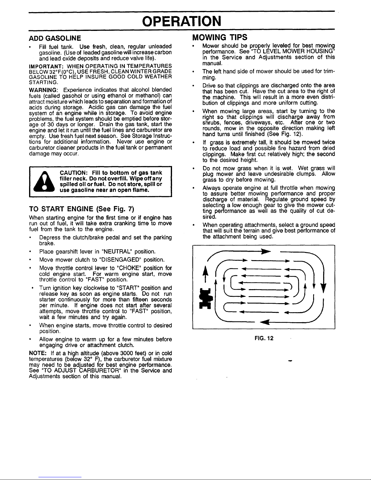
MOWING TIPS
• Mower should be properly leveled for best mowing
performance. See "TO LEVEL MOWER HOUSING"
in the Service and Adjustments section of this
manual.
• The left hand side of mower should be used for trim-
ming.
• Drive so that clippings are discharged onto the area
that has been cut. Have the cut area to the right of
the machine. This will result in a more even distri-
bution of clippings and more uniform cutting.
• When mowing large areas, start by turning to the
right so that clippings will discharge away from
shrubs, fences, driveways, etc. After one or two
rounds, mow in the opposite direction making left
hand turns until finished (See Fig. 12).
• If grass is extremely tall, it should be mowed twice
to reduce load and possible fire hazard from dried
clippings. Make first cut relatively high; the second
to the desired height.
• Do not mow grass when it is wet. Wet grass will
plug mower and leave undesirable clumps. Allow
grass to dry before mowing.
• Always operate engine at full throttle when mowing
to assure better mowing performance and proper
discharge of material. Regulate ground speed by
selecting a low enough gear to give the mower cut-
ting performance as well as the quality of cut de-
sired.
• When operating attachments, select a ground speed
that will suit the terrain and give best performance of
the attachment being used.
FIG. 12
MAINTENANCE
.AI.TE.A.CESC.EDU'E ""
AS YOU COMPLETE
Check BrakeOperation !_ V °
CheckTire Pressure _
T Checkfor LooseFasteners I_ V _
Sharpen/ReplaceMowerBlades !k/t4
_ LubricationChart I_ t_
T Check Battery Level/Recharge
0 Clean BatteryandTerminals V P !_
R CheckTransmissionCooling
AdjustBladeBelt(s)Tension !_
Adjust Motion DriveBelt(s)Tension
Check Engine Oil Level if V'
Change EngineOil _ _1,2,3 V f
Clean Air Filter VIP2
E
N CleanAir Screen V_2
G Inspect Muffler/Spark Arrester V P
I Replace Oil Filter(If equipped) _.2
NE Clean EngineCooling Fins V'2
Replace Spark Plug _ V _
ReplaceAir FilterPaperCartridge _2
v'
Replace Fuel Filter
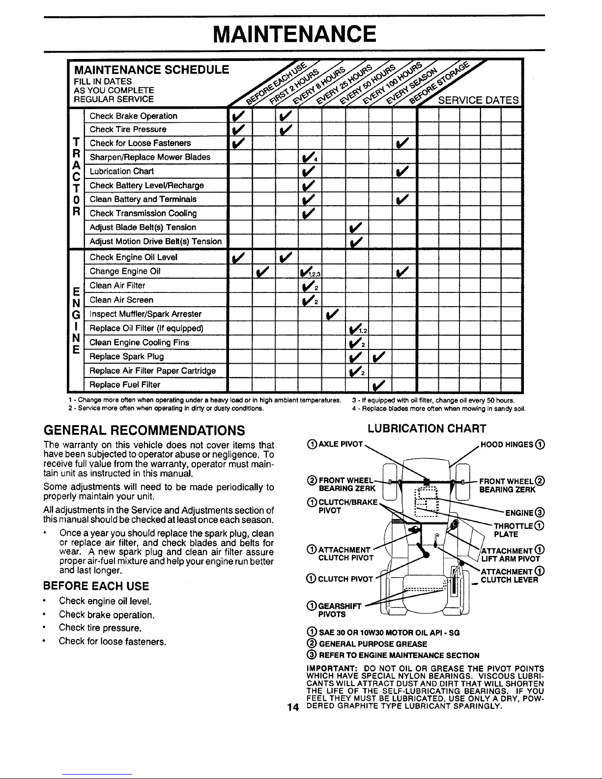
1 - Change more often when operating under a heavy load or in high ambient temperatures.
2 - Service more often when operating in dirty or dusty conditions.
3 - If equipped with oil filter, change oil every 50 hours.
4 - Replace blades more often when mowing in sandy soil.
GENERAL RECOMMENDATIONS
The warranty on this vehicle does not cover items that
have been subjected to operator abuse or negligence. To
receive full value from the warranty, operator must main-
tain unit as instructed in this manual.
Some adjustments will need to be made periodically to
properly maintain your unit.
All adjustments in the Service and Adjustments section of
this manual should be checked at least once each season.
Once a year you should replace the spark plug, clean
or replace air filter, and check blades and belts for
wear. A new spark plug and clean air filter assure
proper air-fuel mixture and help your engine run better
and last longer.
BEFORE EACH USE
• Check engine oil level.
• Check brake operation.
• Check tire pressure.
• Check for loose fasteners.
®
LUBRICATION CHART
,HOOD HINGES (_
@
BEARING ZERK
(_) CLUTCH/BRAKE
PIVOT
CLUTCH PIVOT
(_) CLUTCH PIVOT
WHEEL(_
BEARING ZERK
ENGINE (_)
PLATE
LIFT ARM PIVOT
CLUTCH LEVER
14
(_ GEARSHIFT
PIVOTS
(_) ShE 30 OR 10W30 MOTOR OIL API - SG
(_ GENERAL PURPOSE GREASE
(_) REFER TO ENGINE MAINTENANCE SECTION
IMPORTANT: DO NOT OIL OR GREASE THE PIVOT POINTS
WHICH HAVE SPECIAL NYLON BEARINGS. VISCOUS LUBRI-
CANTS WILL ATTRACT DUST AND DIRT THAT WILL SHORTEN
THE LIFE OF THE SELF-LUBRICATING BEARINGS. IF YOU
FEEL THEY MUST BE LUBRICATED, USE ONLY A DRY, POW-
DERED GRAPHITE TYPE LUBRICANT SPARINGLY.
i
i
MAINTENANCE
LAWN RIDER
Always observe safety rules when performingany mainte-
nance.
BRAKE OPERATION
If unit requires more than six (6) feet stopping distance at
high speed in highest gear, than brake must be adjusted.
(See "TO ADJUST BRAKE" in the Service and Adjust-
ments section of this manual).
TIRES
• Maintain proper air pressure in all tires (See "PROD-
UCT SPECIFICATIONS" on page 3 of this manual).
• Keep tires free ofgasoline, oil, or insect controlchemi-
cals which can harm rubber.
• Avoid stumps, stones, deep ruts, sharp objects and
other hazards that may cause tire damage.
BLADE CARE
For best results mower blades must be kept sharp. The
blades can be sharpened witha file oron a grinding wheel.
We suggest they be sharpened or replaced after every 25
hours of mowing. Check blades more often if mowing in
sandy conditions.
• Do not attempt to sharpen blades while they are on the
mower.
• Replace bent or damaged blades.
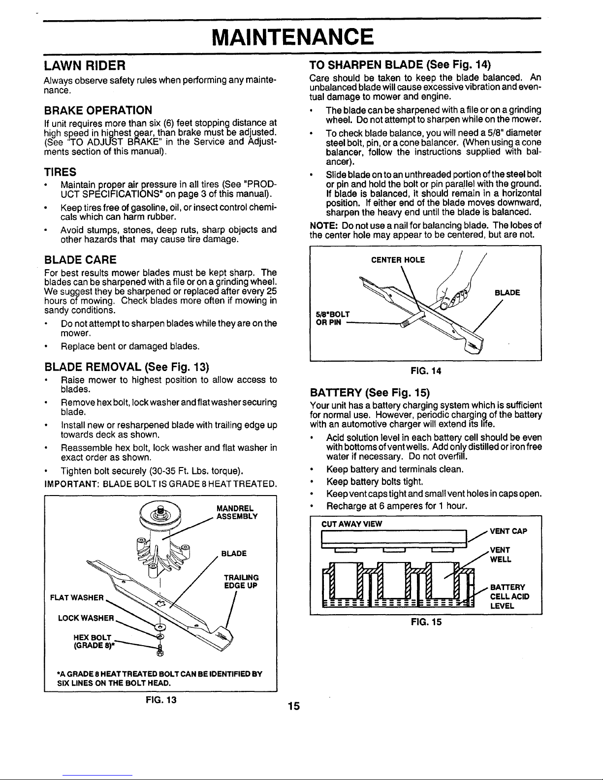
BLADE REMOVAL (See Fig. 13)
• Raise mower to highest position to allow access to
blades.
• Remove hex bolt,lock washer and flat washer securing
blade.
• install new or resharpened blade with trailing edge up
towards deck as shown.
• Reassemble hex bolt, lock washer and flat washer in
exact order as shown.
• Tighten bolt securely (30-35 Ft. Lbs. torque).
IMPORTANT: BLADE BOLT IS GRADE 8 HEATTREATED.
'_ MANDREL
_ ASSEMBLY
/ .LADE
*A GRADE 8 HEAT TREATED BOLT CAN BE IDENTIFIED BY
SIX LINES ON THE BOLT HEAD.
TO SHARPEN BLADE (See Fig. 14)
Care should be taken to keep the blade balanced. An
unbalanced blade will cause excessive vibration and even-
tual damage to mower and engine.
• The blade can be sharpened witha file or on a grinding
wheel. Do not attempt to sharpen while on the mower.
• To check blade balance, you will need a 5/8" diameter
steel bolt, pin, ora cone balancer. (When usinga cone
balancer, follow the instructions supplied with bal-
ancer).
• Slide blade onto an unthreaded portionofthe steel bolt
or pinand hold the boltor pinparallel with the ground.
If blade is balanced, it should remain in a horizontal
position. If either end of the blade moves downward,
sharpen the heavy end until the blade is balanced.
NOTE: Do not use a nailfor balancing blade. The lobes of
the center hole may appear to be centered, but are not.
5/8"BOLT
OR PIN --
CENTER HOLE /j/
DE
FIG. 14
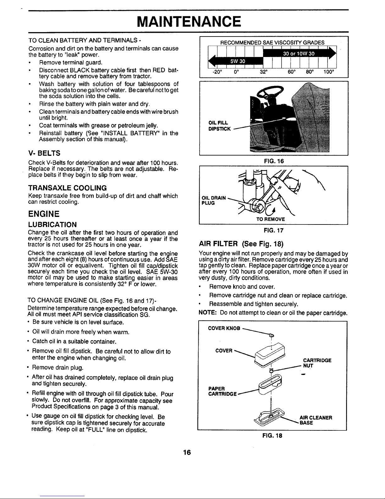
BATTERY (See Fig. 15)
Your unit has a battery charging system which issufficient
for normal use. However, periodic charging of the battery
with an automotive charger will extend its life.
• Acid solution level in each battery cell should be even
with bottoms ofvent wells. Add onlydistilledor ironfree
water if necessary. Do not overfill.
• Keep battery and terminals clean.
• Keep battery bolts tight.
• Keep vent caps tight and smallvent holesincaps open.
• Recharge at 6 amperes for 1 hour.
CUT AWAY VIEW
I I
WELL
FIG. 15
BATTERY
CELL ACID
LEVEL
FIG. 13 15
MAINTENANCE
TO CLEAN BATTERY AND TERMINALS -
Corrosion and dirt on the battery and terminals can cause
the battery to "leak" power.
• Remove terminal guard.
• Disconnect BLACK battery cable first then RED bat-
tery cable and remove battery from tractor.
• Wash battery with solution of four tablespoons of
baking sodatoone gallon of water. Becareful notto get
the soda solution into the cells.
• Rinse the battery with plain water and dry.
• Clean terminals and battery cable ends with wire brush
until bright.
• Coat terminals with grease or petroleum jelly.
• Reinstall battery (See "INSTALL BA]-I-ERY" in the
Assembly section of this manual).
V- BELTS
Check V-Belts for deterioration and wear after 100 hours.
Replace if necessary. The belts are not adjustable. Re-
place belts ifthey begin to slipfrom wear.
TRANSAXLE COOLING
Keep transaxle free from build-up of dirt and chaff which
can restrict cooling.
ENGINE
LUBRICATION
Change the oil after the first two hours of operation and
every 25 hours thereafter or at least once a year if the
tractor is not used for 25 hours in one year.
Check the crankcase oil level before starting the engine
and after each eight (8) hours ofcontinuous use. Add SAE
30W motor oil or equalivent. Tighten oil fill cap/dipstick
securely each time you check the oil level. SAE 5W-30
motor oil may be used to make starting easier in areas
where temperature is consistently 32 ° F or lower.
TO CHANGE ENGINE OIL (See Fig. 16 and 17)-
Determine temperature range expected before oil change.
All oil must meet API service classification SG.
• Be sure vehicle is on level surface.
• Oil will drain more freely when warm.
• Catch oil in a suitable container.
• Remove oil fill dipstick. Be careful not to allow dirt to
enter the engine when changing oil.
• Remove drain plug.
• After oil has drained completely, replace oil drain plug
and tighten securely.
• Refill engine with oil through oil fill dipstick tube. Pour
slowly. Do not overfill. For approximate capacity see
Product Specifications on page 3 of this manual.
• Use gauge on oil filldipstick for checking level. Be
sure dipstick cap is tightened securely for accurate
reading. Keep oil at "FULL" line on dipstick.
RECOMMENDED SAE VISCOSITY GRADES
-20° 0° 32" 60° 80° 100°
OIL FILL
DIPSTICK
FIG. 16
OIL DRAIN
PLUG
TO REMOVE
FIG. 17
AIR FILTER (See Fig. 18)
Your engine will not runproperly and may be damaged by
usinga dirty airfilter. Remove cartridge every 25 hours and
tap gently to clean. Replace paper cartridgeonce a year or
after every 100 hours of operation, more often if used in
very dusty, dirty conditions.
• Remove knob and cover.
• Remove cartridge nut and clean or replace cartridge.
• Reassemble and tighten securely.
NOTE: Do not attempt to clean or oil the paper cartridge.
COVER KNOB
COVER _ CARTRIDGE
CARTRIDGE
I
FIG, 18
16
 Loading...