

Craftsman 917256922 Owner’s Manual

(RI:IFTXMI:1N
MODEL NUMBER 917.256922 OWNER'S MANUAL
oAssembly
oOperation
oCustomer
Responsibilities
oService
oAdjustments
oRepair Parts
Caution:
Read and Follow
all Safety Rules
and Instructions
Before Operating
This Equipment
J

Safe Operation Practices for Ride-On Mowers
SAFETY RULES
IMPORI"ANT: THIS CUTTING MACHINE ISCAPABLE OFAMPUTAT1NG HANDS AND FEET AND TH ROWING OBJECTS,
FAILURE TOOBSERVETHE FOLLOWING SAFETY INSTRUCTIONS COULD RESULT IN SERIOUS INJURY OR DEATH.
I. GENERAL OPERATION
• Read, understand, and follow alt instructions inthe manual
and on the machine before stagging.
• Only allow responsible adults, who are familiar with the
instructions, to operate the machine.
• Clear the area of objects such as rocks, toys, wire, etc.,
which could be picked up and thrown by the blade.
• Be sure the area is clear of other people before mowing. Stop
machine if anyone enters the area.
• Never carry passengers..
• Do not mow in reverse unless absolutely necessary. Always
look down and behind before and while backing
• Be aware of the mower discharge direction and do not point
it at anyone. Do not operate the mower without either the
entire grass catcher or the guard in place.
• Slow down before turning
• Never leave a running machine unattended Always turn off
blades, set parking brake, stop engine, and remove keys
before dismounting.
• Turn off blades when not mowing
• Stop engine before removing grass catcher or unclogging
chute.
• Mow only in daylight or good artificial fight..
• Do not operate the machine while under the influence of
alcohol or drugs.
• Watch for traffic when operating near or crossing roadways.
• Use extra care when loading or unloading the machine into
a trailer or truck.
II, SLOPE OPERATION
Slopes are a major factor related to loss-of-control and tipover
accidents, which can result in severe injury or death_ All slopes
require extra caution. Ifyou cannot back up the slope orif you feel
uneasy on it, do not mow it
DO:
• Mow up and down slopes, not across
• Remove obstacles such as rocks, tree limbs, etc..
• Watch for holes, ruts, or bumps. Uneven terrain could
overturn the machine Taft grass can hide obstacles..
• Use stow speed Choose a low gear so that you will not have
to stop or shift while on the slope
• Follow the manufacturer's recommendations for wheel
weights or counterweights to improve stability
• Use extra care with grass catchers or other attachments.
These can change the stability of the machine.
• Keep all movement on the slopes slow and gradual. Do not
make sudden changes in speed or direction.
• Avoid starting or stopping on a.slope** If tires lose traction,
disengage the blades and proceed slowly straight down the
slope
DO NOT:
• Do not turn on slopes unless necessary, and then, turn slowly
and gradually downhill, if possible.
• Do not mow near drop-offs, ditches, or embankments. The
mower could suddenly tum over if a wheel is over the edge
of a ctiff or ditch, or if an edge caves in.
• Do not mow on wet grass Reduced traction could cause
sliding.
• Do not try to stabilize the machine by putting your foot on the
ground.
• Do not use grass catcher on steep slopes.
IlL CHILDREN
Tragic accidents can occur if the operator is not alert to the
presence of children. Children are often attracted tothe machine
and the mowing activity Neverassume that children witl remain
where you last saw them.
• Keep children out of the mowing area and underthe watchful
care of anolher responsible adult.
• Be alert and turn machine off ifchildren enter the area.
° Before and when backing, look behind and down for small
children.
• Never carry children. They mayfall off and be seriously
injured or interfere with safe machine operation
° Never allow children to operate the machine.
• Use extra care when approaching blind comers, shrubs,
trees, or other objects that may obscure vision
IV. SERVICE
° Use extra care in handling gasoline and other fuels. Theyare
flammable and vapors are explosive
Use only an approved container.
Never remove gas cap or add fuel with the engine
running. Allow engine to coot before refueling. Do not
smoke.
Never refuel the machine indoors.
Never store the machine or fuel container inside where
there is an open flame, such as a water heater.
- Never run a machine inside a closed area.
• Keep nuts and bolts, especially blade attachment bolts, tight
and keep equipment in good condition.
. Never tamper with safety devices.. Check their proper
operation regularly.
• Keep machine free of grass, leaves, orotherdebds build-up.
C_ean oil or fuet spillage. Allow machine to cool before
stodng.
- Stop and inspect the equipment if you strike an object.
Repair, if necessary, before restagging.
° Never make adjustments or repairs with the engine running
• Grass catcher components are subject towear, damage, and
deterioration, which could expose moving parts or allow
objects to be thrown. Frequently check components and
replace with manufacturer's recommended parts, when nec-
essary
• Mower blades are sharp and can cut. Wrap the blade(s) or
wear gloves, and use extra caution when servicing them..
• Check brake operation frequently Adjust and service as
required.
LOOkfor thistly"rebel to point out impor-
tant safety precautions, It means
CAUTION_H BECOME ALERTH! YOUR
SAFETY tS INVOLVED.
CAUTION: Always disconnect spark
plug wire and place wire where it cannot
contact spark plug in order to prevent
accidental starting when setting up,
transporting, adjusting or making
repairs.
i,i H, HII

CONGRATULATIONS on your purchase of a Sears trac-
tor,. It has been designed, engineered and manufactured
to give you the best possible dependability and perfor-
mance.
Should you experience any problem you cannot easily
remedy, please contact your nearest Sears Service
Center/DepartmenL We have competent, well4rained
technicians and the proper tools to service or repair this
tractor.
Please read and retain this manual.. The instructions will
enable you to assemble and maintain your tractor prop-
erly_ Always observe the "SAFETY RULES".
MODEL
NUMBER 917256922
SERIAL
NUMBER
DATE OF PURCHASE
THE MODEL AND SERIAL NUMBERS WILL BE FOUND
ON A PLATE UNDER THE SEAT.
YOU SHOULD RECORD BOTH SERIAL NUMBER AND
DATE OF PURCHASE AND KEEP IN A SAFE PLACE
FOR FUTURE REFERENCE
PRODUCT SPECIFICATIONS
HORSEPOWER: 12
GASOLINE CAPACITY: 14 GALLONS
UNLEADED REGULAR
OIL (3.0 PINTS) SAE 30 (above 32°F)
5W-30 (below 32°F)
SPARK PLUG (GAP 030IN.): CHAMPION RJ-19LM
STD361458
VALVE CLEARANCE: INTAKE. 005 - .007 IN
EXHAUST ,009 - .011IN.
GROUND SPEED: FORWARD
1st .95 MPH
2rd 194 MPH
3th 2491 MPH
4th 3.71 MPH
5th 476 MPH
REVERSE: 1.46 MPH
TIRE PRESSURE: FRONT: 14PSI
REAR: 12 PSI
CHARGING SYSTEM: 5 AMPS HEADLIGHTS
3 AMPS BATTERY
BLADEBOLT TORQUE: 30-35 FT,.LBS
MAINTENANCE AGREEMENT
A Sears maintenance agreement is available on this trac-
tor. Contact your nearest Sears store for details.
CUSTOMER RESPONSIBILITHES
= Read and observe the safety rules.
. Fotlow a regular schedule in maintaining, caring for and
using your tractor.
• Fotlowthe instructions under"Customer Responsibili-
ties" and "Storage" sections of this manual.
WARNING: This tractor is equipped with an internal
combustion engine and should not be used on or near any
unimproved forest-covered, brush-covered or grass-cov-
ered land unless the engine's exhaust system is equipped
with a spark arrester meeting applicable local or state laws
(if any). If aspark arrester is used, it should be maintained
in effective working order by the operator,
In the state of California the above is required by law
(Sect on 4442 of the California Public Resources Cede).
Other states may have similar laws. Federal laws apply on
federal lands. A spark arrester for the muffler is available
through your nearest Sears autho rized service center (See
REPAIR PARTS section of this manual)°
LIMITED TWO YEAR WARRANTY ON ELECTRIC START RIDING EQUIPMENT
For two (2) years from the date of purchase, if this riding equipment is maintained, lubricated and tuned up according to the
instructions in the owneCsmanual, Sears will repair or replace, free of charge, any parts found to be defective in material or
workmanship.
This Warranty does notcover:
* Expendable itemswhich become wornduring normaluse,such asblades, spark plugs,air cleaners andbelts.
. Tire replacement or repair causedby puncturesfrom outside objects,such as nails,thorns, stumps, or glass.
, Repairs necessary because of operatorabuse, negligence, improper storage or accident or the failure to maintain the
equipment according to the instructionscontained in the owner's manual .........
, Riding equipment used forcommercia,[orrental purposes.[ ""
LIMITED 90 DAY WARRANTY ON BATTERY
For 90 days from date of purchase, if any battery included withthisridingequipment proves defective in material or workmanship
and our testingdetermines the battery wil!not hold a charge, Searswill replace the battery at nocharge.
WARRANTY SERVICE IS AVAILABLE BY RETURNING THE RIDING EQUIPMENT TO THE NEAREST SEARS SERVICE
CENTER/DEPARTMENT INTHE UNITED STATES,,
This Warranty gives you specific legal rights, and you may atso have other rights which may vary from state to state
SEARS, ROEBUCK AND CO. D/817 WA, HOFFMAN ESTATES, ILLINOIS 60179
, , i lU i,,Ul
3

TABLE OF CONTENTS
......... i...... i,,i,, ........................................... iii ,Ull
SAFETY RULES ............................................................ 2
PRODUCT SPECIFICATIONS ...................................... 3
CUSTOMER RESPONSIBILITIES ..................... 3, 14-'17
WARRANTY ................................................................ .3
TABLE OF CONTENTS ................................................ 4
INDEX ............................................................................ 4
TRACTOR ACCESSORIES .......................................... 5
ASSEMBLY ................................................................. 7-9
aNDEX
OPERATION ........................................................... 10-'13
MAINTENANCE SCHEDULE ...................................... 14
SERVICE AND ADJUSTMENTS ............................ 18-22
STORAGE ................................................................... 23
TROUBLESHOOTING ........................................... 24,-25
REPAIR PARTS - TRACTOR ................................ 27-43
REPAIR PARTS - ENGINE .................................... 46-50
PARTS ORDERING/SERVICE .................. BACK PAGE
A
Accessories .............................................. 5
Adjustments:
Brake ............................................... 20
Carburetor ....................................... 22
Mower
Front-To-Back ............................... 1 9
Side-To-Side ............................ 19
Throttle Control Cable ........................22
Air Filter, Engine ................................... 17
Air Screen, Engine .............................. 17
Assembly ............................................... 7-9
B
Battery:
Charging ......................................... 8
Cleaning ...... .....................................16
Installation...................................... 9
LeveIs ............................... ............ 8,15
Preparation ............................................8
Starting with Weak Battery ............21
Storage ...............................................23
Terminals ..........................................16
Belt:
Motion Drive
Removal/Replacement ........... 20
Blade:
Sharpening ................................. 15
Replacement ................................... 15
Brake Adjustment .............................. 20
C
CarburetorAdjustment ........................ 22
Controls, Tractor .................................. 10
Custome r Responsibitities ............3,14-17
Engine:
Air Filter .................................. 17
Air Filter Foam Pre-Cfeaner .....17
Air Screen, Engine ................. 17
Battery ........................................ 15
Cooling Fins, Engine .............. 17
Engine Oil ......................... 16
Fuel Filter ............................... 17
Spark Plugs ........................... 17
Tractor:
Blade .......................................... 15
Lubrication Chart .................... 14
Maintenance Schedule ............ 14
Tire Care ....................... 8,15,2t
Cutting Height, Mower ....................... 12
E
Electrical:
Interlocks and Relays ................ 21
Schematic ...........................................26
Wiring Diagram ......................... 28
Engine:
Air Filter .............................................17
Air Filter Foam Pre-Cleaner .............17
Air Screen ...................................... 17
Cooling Fins, Engine .......................17
Oil Change .......................................16
Oil Level .................................... 12,16
Oil Type ........................................... 16
Preparation ................................ 12
Repair Parts ............................ 46-50
Starting ........................................... t 3
Storage ............................................ 23
F
Filter:
Air Filter ........................................... t7
Air Filter Foam Pre-Oleaner ............17
Fuel ............................................ 17
Fuel:
Type ............................................... 13
Storage .................................. ............ 23
Fuse ............................................................... 21
H
Hood Removal/Installation ........ 21
L
Leveling Mower Deck ..............................19
Lubrication:
Chart ....................................................t4
M
Maintenance Schedule ..................... I 4
Mower:
Adjustment, Front4o-Back ........... 19
Adjustment, Side-to-Side ............ 19
Blade Sharpening ..................... 15
Blade Replacement ..........................15
Cutting Height ................................ 12
Installation ..............................:_....... 18
Operation ............................................12
Removal ......................................... 18
Mowing Tips ............................................ 13
Muffler ........................................... 17
Spark Arrester ........................... 3,38
O
Oil:
Cold Weather Conditions .........12,16
Engine .....................................................16
Storage ....................................................23
Operation ........................................ 10-13
Operating Mower ........................................... 12
Options:
Accessodes .................................... ............... 5
Spark Arrester ............................... 3,38
P
Parking Brake ........................................10-11
Parts Bag .............................................................6
Pads, Replacement/Repair ...............27-43
Product Specifications ..................................3
R
Repair Parts ..............................................27-43
S
Safety Rules .....................................................2
Seat ................................................................ 8
Service and Adjustments ............... 18-22
Carburetor ........................................22
Fuse ................................... ............... 21
Hood RemovaVlnstallation ..............21
Motion Drive Belt
RemovaltReplacement ............ 20
Mower Adjustment:
Front- to-Back .......................... 19
Side4o-Side ...................................19
Mower Removal ............................ !8
Tire Care ................................ 8,15,21
Slope Guide Sheet ............................... 51
Spark Plugs ...................................................t7
Specifications ............................... ..................... 3
Starting the Engine ...........................12-13
Steering Wheel .........................................7,20
Stopping the Tractor ..................................11
Storage ..................................................23
T
Throttle Control Cable Adjustment -_ 22
Tires ............................................. 8,15,21
Trouble Shooting Chart ......................24-25
Transaxle Repair Parts .....................44-45
W
Warranty ................................................... 3
Wiring Diagram ...................................... 28
Wiring Schematic ............................... 26

, H=I H, , , =I,"H'H ............................ I I II I I=INH,H=
ACCESSORIES AND ATTACHMENTS
.......................... i IIIIIIH= N,=,II= ii 1,1111111,11
These accessories and attachments were available when theunitwas purchased. They are also available at most Sears retail outlets,
catalog and service centers. Most Sears stores can order these items for you when you providethe model number ofyour tractor.
ENGINE
SPARK PLUG MUFFLER AiR FILTER GAS CAN ENGINE OIL STABILIZER
PERFORMANCE
Sears offersa widevarietyofattachments thatfit your vehicle, Manyofthese are listedbelow withbrief explanationsofhowthey can
he_pyou Thislistwascurrentatthetimeofpublication; however, itmaychangeinfuture years°moreattachments may beadded,changes
may be made in these attachments, or some may no longerbe available or fit your model Contact your nearest Sears store for the
accessories and attachments that are available for your unit.
Most ofthese attachments do not require additional hitches or conversion kits (those that do are indicated)and are designed for easy
attachingand detaching
MAINTENANCE
BLADES 1 BELTS
PERMANEX BAGGER lets you collect grass clippings and
leaves for a healthier, heater looking iawn., Two Permanex
containers hold 30-gallon plastic bags
LAWN SWEEPERS let you coliect grass clippings and leaves,
CARTS make hauiing easy Variety of sizes available
ROLLER for smoother lawn surface. 36-inch wide, 18-inch
diameter water-tight drum holds up to 390 tbs of weight, Rounded
edges prevent harm to turf_ Adjustable scraper automatically
cleans drum.
SPREADER/SEEDERS make seeding, fertilizing, and weed
kitling easy, Broadcast spreaders are also useful for granular
de-icers and sand,
CORING AERATOR takes small plugsout of soil to allow mois-
ture and nutrients to reach grass roots. 36-inch swath. 24
hardened steel coring tips 150 lb.capacity weight tray
AERATOR promotes deep root growth for a healthy lawnoTa-
pered 2_5-inchsteel spikes mounted on t 0-inch diameter discs
puncturehofes in soil at close intervals to let moisture soak in_
Steelweight tray for increased penetration.
MULCHRAKE/DETHATCHER loosens soiland flips thatch and
mattedleavestolawnsurfacefor easy pickup. Twentyspring tine
teeth. Useful topreparebareareasfor seeding. Available forrear
mounting only
SPRAYERS use 12-volt DC electric motor that connects to the
tractor battery or other 12-volt source Includes booms for
automatic spraying when pulling,and hand held wand for spot
spraying. Wand has adjustable spray pattern For applying
herbicides, insecticides,fungicides, and liquid fertilizers_

i ,=,,=, IHH'H
,,,=,,,i,=,,i i .........................
CONTENTS OF
_ ,ul,,=
Parts Bag contents shown full size
............. ==,,, =
©
(1) Large
Flat Washer
(1) Locknut 3/8-24
HARDWARE PACK
..... t, ,,u=
,,u,,,,H
Parts packed separately in carton
Steering
Wheel
,1 ....
Seat
,1==
O
Battery acid
Battery
(1) Hex Bolt 1/2-13 x 1
(1) Shoulder Bolt 5/16-18
(1) Lock Washer 'I/2
(1) Washer 17/32 x 1-3/16 x 12 Gauge
=,,,nN,I ' U',"11',1 =.... n'l
(2) Hex Bolts 1/4-20 x 3/4
(2) Hex Nuts 1f4-20
@
Steering
Sleeve
Owner's Manual
i ,,1=1, ,,=, ],,l.,rl_ .... i=' i"
Parts bag contents not shown full size
_ ' Wheel
Steering Wheel Insert
Adapter
Steering CliP
, =,H =,,u, _=--
II_f- _ll Steering
Parts Bag
i,, ='=' , m,,,
2) Keys
i i
(2) Lock Washers 1/4
(2) Washers 9/32 x 5/8 x 16 Gauge
.... 1,1
®
15° Slope Sheet
,=,
L__
Battery Caps
and Instructions
,,, =

ASSEMBLY
' i -=, ,=,,,,, .... =1 ,,
Your new tractor has been assembled at the factory withthe exception of those parts left unassembled for shipping purposes.
To ensure safe and proper operation of your tractor, all parts and hardware you assemble must be tightened securely. Use
the correct tools as necessary to insure proper tightnes&
TOOLS REQUIRED FOR ASSEMBLY
A socket wrench set will make assembly easier, Standard
wrench sizes are listed,,
(1) 9/16" wrench
(2) 7/16" wrenches
(1) 1/2" wrench
(1) 3/4" wrench
When right and left hand are mentioned in this manual, it
means when you are in the operating position (seated
behind the steering wheel).,
Pliers
Tire pressure gauge
Screwdriver
Utility knife
TO REMOVE TRACTOR FROM CARTON
UNPACK CARTON
o Remove all accessible loose parts and parts Cartons
from carton (See page 6)_
o Cut along lines on the carton, from top to bottom, all
four corners of carton and lay panels flat,
- Check for any additional loose parts or cartons and
remove,,
BEFORE ROLLING TRACTOR OFF SKID
ATTACH STEERING WHEEL
POSITION STEERING SHAFT (See Fig, 1) -
, Lift hood.
• Pull steering shaft up to engage gears..
o Push steering clip through hole on steering shaft at 45 °
(hole is located under dash and above lower steering
bushing),
o Push steering clip onto steering shaft until steering clip
snaps into place,,
INSTALL STEERING WHEEL (See Fig, 2) -
o Slide the steering sleeve over the steering shaft (bot-
tom of sleeve goes over ring on dash).
o Slide steering wheel adapter onto upper steering shaft,
o Position front wheels of the tractor so they are pointing
straight forward°
• Position steering wheel so cross bars are horizontal
(teft to right) and slide onto adapter.
o Assemble large flat washer and 3/8-24 locknut and
tighten securety.
- Snap insert into center of steering wheel°
, Remove protective plastic from tractor hood and grill,
IMPORTANT: CHECK FOR AND REMOVE ANY STAPLES IN
SKID THAT MAY PUNCTURE TIRES WHERE TRACTOR ISTO
ROLLOFF SKID
TO ROLL TRACTOR OFF SKID (See Fig. 7)
• Raise mower lift lever to its highest position,
o Place gearshift lever in "NEUTRAL" position.
,, Release parking brake by depressing clutch/brake
pedal
• Roll tractor backwards off skid
• Remove banding holding discharge guard up against
tractor.
STEERING SHAFT
STEERING CLIP
LOWER
STEERING
BUSHING
FIG. 1
STEERING WHEEL
STEERING WHEEL
STEERING WHEEL
FIG. 2
..... i .................. ,M,,
ii lU ....... i,U,UlUll,,nll,,,,n..... ii,l,,ll,ii I " I,'1
ASSEMBLY
HOW TO SET UP YOUR TRACTOR
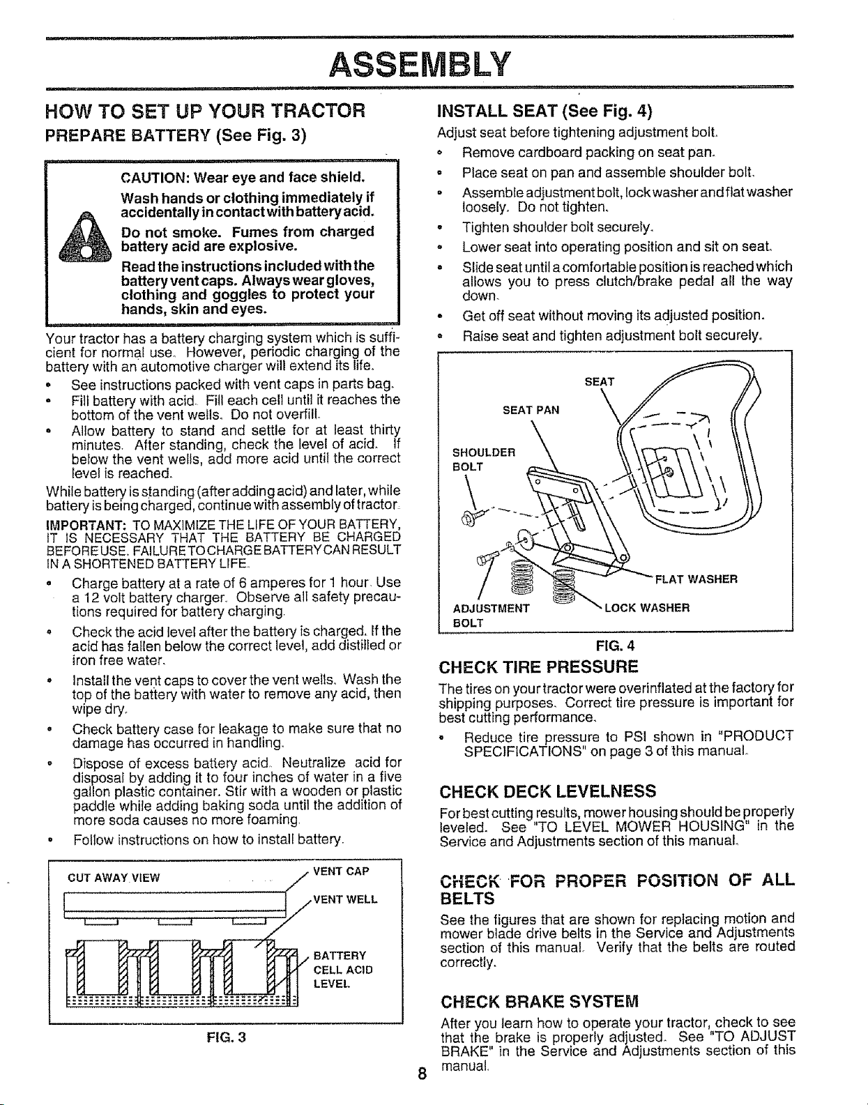
PREPARE BATTERY (See Fig, 3)
CAUTION: Wear eye and face shield.
Wash hands or clothing immediately if
accidentally in contactwith battery acid.
Do not smoke. Fumes from charged
battery acid are explosive.
Read the instructions included with the
battery vent caps. Always wear gloves,
clothing and goggles to protect your
hands, skin and eyes.
Your tractor has a battery charging system which is suffi-
cient for normal use° However, periodic charging of the
battery with an automotive charger will extend its lifeo
o See instructionspacked with vent caps in parts bag.
- Fill battery with acid. Fill each cell until it reaches the
bottom of the vent wells. Do not overfill
o Allow battery to stand and settle for at least thirty
minutes, After standing, check the level of acid. If
below the vent wells, add more acid until the correct
level is reached.
While battery is standing (after adding acid) and later, while
battery isbeing charged, continue with assembly of tractor_
IMPORTANT: TO MAXIMIZE THE LIFE OFYOUR BATTERY,
IT IS NECESSARY THAT THE BATTERY BE CHARGED
BEFOREUSE, FAILURETOCHARGE BATTERYCAN RESULT
IN A SHORTENED BATTERY LIFE.,
• Charge battery at a rate of 6 amperes for 1 hour. Use
a 12 volt battery charger., Observe alt safety precau-
tions required for battery charging.
o Check the acid level after the battery is charged, If the
acid has faflen below the correct level, add distilled or
iron free water.
. Install the vent caps to cover the vent wells,, Wash the
top of the battery with water to remove any acid, then
wipe dry.
o Check battery case for leakage to make sure that no
damage has occurred in handling,,
o Dispose of excess battery acid,. Neutralize acid for
disposal by adding it to four inches of water in a five
gallon plastic container. Stir with a wooden or plastic
paddle while adding baking soda until the addition of
more soda causes no more foaming,
• Foliow instructions on how to install battery_
..... =....
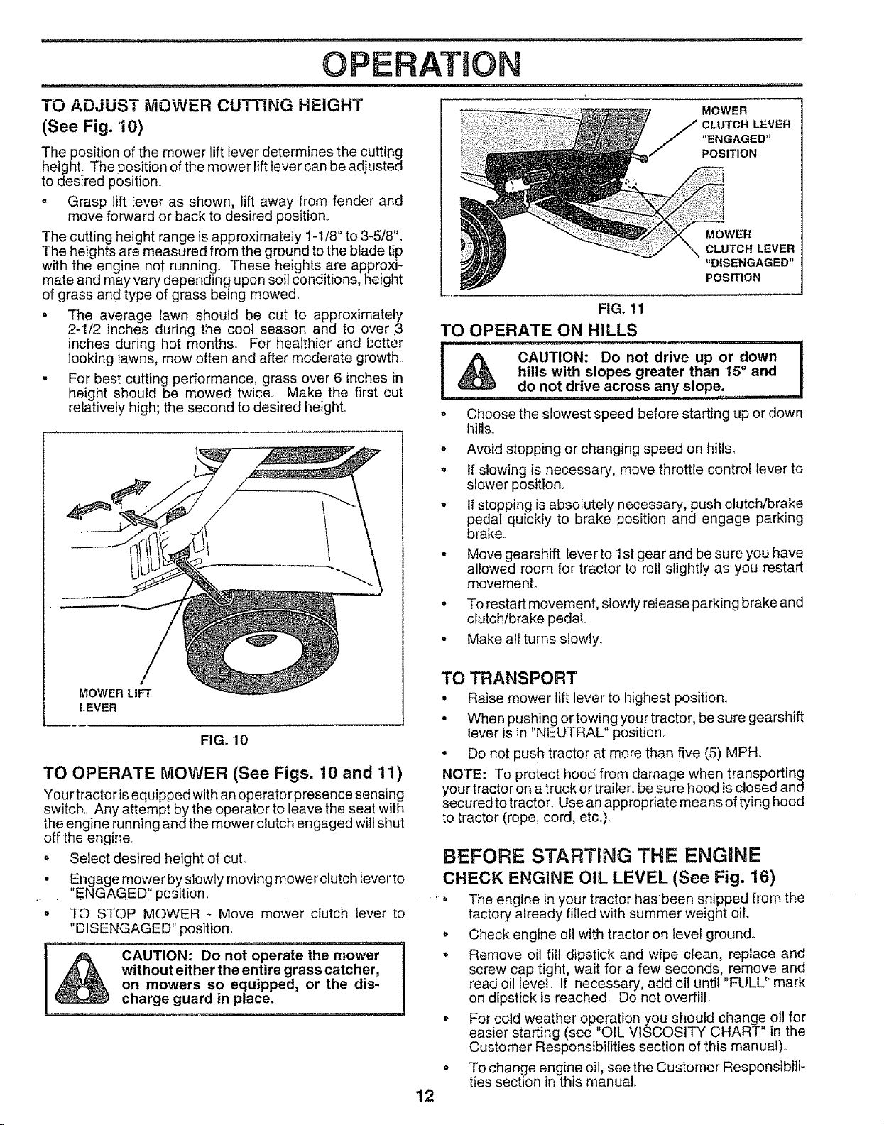
INSTALL SEAT (See Fig. 4)
Adjust seat before tightening adjustment bolt.
o Remove cardboard packing on seat pan_
,, Place seat on pan and assemble shoulder bolt.
° Assemble adjustment bolt, lockwasher andfiatwasher
loosely,, Do not tighten.
= Tighten shoulder bolt securely.
° Lower seat into operating position and sit on seat,,
. Slide seat until a comfortable position is reached which
allows you to press clutch/brake pedal all the way
down.
° Get off seat without moving its adjusted position.
o Raise seat and tighten adjustment bolt securely.
SEAT
SEAT PAN
SHOULDER
BOLT
FLAT WASHER
ADJUSTMENT LOCK WASHER
BOLT
FIG. 4
CHECK TIRE PRESSURE
The tires on you r tractor were overinflated at the factory for
shipping purposes. Correct tire pressure is important for
best cutting performance.
- Reduce tire pressure to PSI shown in "PRODUCT
SPECIFICATIONS" on page 3 of this manual.
CHECK DECK LEVELNESS
For best cutting results, mower housing should be properly
leveled. See "TO LEVEL MOWER HOUSING" in the
Service and Adjustments section of this manual.
CUT AWAY VIEW
FIG. 3
VENT CAP
VENT WELL
BATTERY
CELL ACID
LEVEL
CHECK FOR PROPER POSiTiON OF ALL
BELTS
See the figures that are shown for replacing motion and
mower blade drive belts in the Service and Adjustments
section of this manual. Verify that the belts are routed
correctly,
CHECK BRAKE SYSTEM
After you learn how to operate your tractor, check to see
that the brake is properly adjusted. See "TO ADJUST
BRAKE" in the Service and Adjustments section of this
manual,

...... ,,,-, , ................ -,,,,,,,i, ii iiiii1,,,11 i ,,
ASSEMBLY
+
INSTALL BATTERY (See Figs. 5 & 6)
........ i i,iiiiiiii
CAUTION: Do not short battery termi-
nals+ Before installing battery, remove
rings, etc.
metal bracelets, wristwatch bands,
Positive terminal must be connected
first to prevent sparking from acciden-
tal grounding.
.... =,=1,, ,............. , ........
Lift seat to raised position
* Open battery box door.
, Lower battery into battery box with battery terminals
toward front of tractor..
o Be sure drain tube is attached to bottom of battery box
and tube passes through hole in chassis for proper
drainage.
, First connect RED battery cable and RED fused igni-
tion wire to positive (+) battery terminal with hex bolt,
flat washer, lock washer and hex nut as shown. Tighten
securely..
o Connect BLACK grounding cable to negative (-) bat-
tery terminal with remaining hex bolt, flat washer, lock
washer and hex nut+ Tighten securely.
+ Close battery box door
Use terminal access doors for:
o Inspection for secure connections (to tighten hard +
ware).
- Inspection forcorrosion_
o Testing battery+
+ Jumping (if required)
Periodic charging.
BATTERY
BOX DOOR
NEGATIVE
POSITIVE (BLACK)
(RED) CABLE CABLE
LOCK
WASHER
FLAT
WASHER
HEX
HEX
BOLT
BATTERY
BOX
VENT CAPS
FIG. 6
,/CHECKLIST
BEFORE YOU OPERATE AND ENJOY YOUR NEW
TRACTOR, WE WISH TO ASSURE THAT YOU RECEIVE
THE BESTPERFORMANCEAND SATISFACTION FROM
THIS QUALITY PRODUCT,
PLEASE REVIEW THE FOLLOWING CHECKLIST:
J All assembly instructions have been completed.,
¢' No remaining loose parts in carton,,
¢' Batteryis properly prepared and charged,, (Minimum
1 hour at 6 amps)+
v" Seat is adjusted c_mfortably and tightened securely.
v" All tires are properly inflated. (For shipping purposes,
the tires were overinflated at the factory).
¢' Be sure mower deck is properly leveled side-to-side/
front4o-rear for best cutting results+ (Tires must be
properly inflated for leveling).
v" Check mower and drive belts. Be sure they are routed
properly around pulleys and inside all belt keepers.
¢" Check wiring. See that all connections are still secure
and wires are properly clamped+
WHtLE LEARNING HOW TO USE YOUR TRACTOR, PAY
EXTRA A TTENTION TO THEFOLLOWING IMPORTANT
ITEMS:
,/ Engine oil is at proper level.
_" Fuel tank is filled with fresh, clean, regular unleaded
gasoline.
,/ Become familiar with all controls + their location and
function. Operate them before you start the engine.
,/ Be sure brake system is in safe operating condition.
POSITIVE (+) TER&,_INAL NEGATIVE (-) TERMINAL
FroG+5 9

OPERATION
KNOW YOUR TRACTOR
READ THIS OWNER'S MANUAL & SAFETY RULES BEFORE OPERATING YOUR TRACTOR.
Compare the illustrations with your tractor to familiarize yourself with the Iocation of various controls and adjustments. Save
this manual for future reference_
THROTTL_
CHOKE
FUEL CAP
CLUTCH/
BRAKE
PEDAL
_TROL
MOWER
LEVER
PARKING
BRAKE
LEVER
MOWER IGNITION
LIFT SWITCH
LEVER
Sears tractors conform to the safety standards of the American National Standards Institute,
IGNITION SWITCH: Used for starting and stopping the
engine.
THROTTLE/CHOKE CONTROL: Used for starting and
controlling engine speed,
CLUTCH/BRAKE PEDAL: Usedfor declutching and brak-
ing the tractor and starting the engine.
GEARSHIFT
LEVER
FiG. 7
GEARSHIFT LEVER: Selects tlie gpe_)d and di_ectiorl Of
tractor,
PARKING BRAKE LEVER: Locks clutch/brake pedal into
the brake position,
MOWER CLUTCH LEVER: Used to engage the mower
blades
MOWER LIFT LEVER: Used to raise and lower the mower
deck°
10

OPERATION
iii , ,i,1,11 i iii ii1,1,11111111111111
The operation of any tractor can result inforeign objects thrown into the eyes, which can result
in severe eye damage, Always wear safety glasses or eye shields before starting your tractor
and while moving. We recommend wide vision safety mask for over the spectacles or standard
safety glasses.
HOW TO USE YOUR TRACTOR
TO SET PARKING BRAKE (See Fig. 8)
° Depress clutch/brake pedal into full "BRAKE" position
and hold.
° Place parking brake leverin"ENGAGED" position and
release pressure from clutch/brake pedal Pedal should
remain in "BRAKE" position_ Make sure parking brake
wilt ho_d tractor secure
PARKING BRAKE"ENGAGED" MOWER CLUTCH
LEVER"ENGAGED"
'*DISENGAGED"
CLUTCH/BRAKE
PEDAL"BRAKE"
POSITION
FIG. 8
inln I u "J
CAUTION: Always stop tractor com-
pletely, as described above, before leav-
ing the operator's position; to empty
grass catcher, etc.
i ii, i,i1,1,1111,11,1,,111 i iii iii,
TO USE THROTTLE CONTROL (See Fig. 9)
Always operate engine at full throttle.
o Operating engine at less than full throttle reduces the
battery charging rate,,
. Full throttte offers the best bagging and mower perfor-
mance
TO MOVE FORWARD AND BACKWARD
(See Figs. 8 and 9)
The direction and speed of movement is controlled by the
gearshift lever.
= Start tractor with clutch/brake pedal depressed and
gearshift Iever in "NEUTRAL" position,,
= Move gearshift lever to desired position.
° Slowly release clutch/brake pedal to start movement.
IMPORTANT: BRING TRACTOR TO A COMPLETE STOP
BEFORESH[FTING OR CHANGING GEARS, FAILURE
TO DO SO WiLL SHORTEN THE USEFUL LIFE OF YOUR
TRANSAXLE.
I
STOPPING (See Figs. 8 and 9)
MOWER BLADES -
° Move mower clutch lever to "DISENGAGED" position.
GROUND DRIVE
• Depress clutch/brake pedal into full "BRAKE" position,
o Move gearshift lever to "NEUTRAL" position.
ENGINE -
• Move throttle contro{ to "SLOW" position.
NOTE: Failure to move throttle control to "SLOW" position
or allowing engine to idle before stopping may cause
engine to "backfire",
° Turn ignition key to "OFF" position and remove key.
......... Always remove key when Leaving trsctor to prevent
unauthorized use.
= Never use choke to stop engine.
NOTE: Under certain conditions when tractor is standing
idle with engine running, hot engine exhaust gasses may
cause "browning" of grass To etiminate this possibility,
always stop engine when stopping tractor on grass cov-
ered areas,,
CLUTCH/ THROTTLE/
BRAKE
PEDAL CONTROL
GEARSHIFT
LEVER
PARKING
BRAKE
IGNITION
FIG. 9
11
U'I
OPERATION
TO ADJUST MOWER CUTTING HEIGHT
(See Fig. 10)
The position of the mower lift lever determines the cutting
height° The position of the mower Iift lever can be adjusted
to desired position.
o Grasp lift Iever as shown, lift away from fender and
move forward or back to desired position,.
The cutting height range isapproximately 1-t/8" to 3-5/8".
The heights are measured from the ground to the blade tip
with the engine not running. These heights are approxi-
mate and may vary depending upon soil conditions, height
of grass and type of grass being mowed.
• The average lawn should be cut to approximately
2-1/2 inches during the cooI season and to over 3
inches during hot months. For healthier and better
looking lawns, mow often and after moderate growth.
. For best cutting performance, grass over 6 inches in
height should be mowed twice Make the first cut
relatively high; the second to desired height.
MOWER
CLUTCH LEVER
"ENGAGED"
POSITION
MOWER
CLUTCH LEVER
"DISENGAGED"
POSITION
FIG. 11
TO OPERATE ON HILLS
I _% CAUTION: Do not drive up or down
hills with slopes greater than 15° and I
do not drive across any slope: ..... I
= i ,, ,,1,,, •
o Choose the slowest speed before starting up or down
hills,.
o Avoid stopping or changing speed on hills.
o If slowing is necessary, move throttle control lever to
siower position.
o If stopping is absolutely necessary, push clutch/brake
pedal quickly to brake position and engage parking
brake,
° Move gearshift lever to 1st gear and be su re you have
allowed room for tractor to roll slightly as you restart
movemenL
- To restart movement, slowly release parking brake and
clutch/brake pedal
• Make all turns slowly,
I
MOWER LIFT
LEVER
FIG. 10
TO OPERATE MOWER (See Figs. 10 and 11)
Your tractor is equipped with anoperator presence sensing
switch,. Any attempt by the operator to leave the seat with
the engine running and the mower clutch engaged will shut
off the engine.
o Select desired height of cut.
• Engage mower byslowly moving mower clutch lever to
"ENGAGED" position.
• TO STOP MOWER - Move mower clutch lever to
"DISENGAGED" position.
,,, , ,,,,,, ...........
without either the entire grass catcher,
CAUTION: Do not operate the mower
on mowers so equipped, or the dis-
=== ............
charge guard in place.
TO TRANSPORT
° Raise mower lift lever to highest position.
• When pushing ortowingyourtractor, be sure gearshift
lever is in "NEUTRAL" position..
o Do not push tractor at more than five (5) MPH.
NOTE: To protect hood from damage when transporting
your tractor on a truck or trailer, be sure hood is closed and
securedtotractor. Use an appropriate means of tying hood
to tractor (rope, cord, etc.).
BEFORE STARTING THE ENGaNE
CHECK ENGINE OIL LEVEL (See Fig. 16)
. The engine in your tractor has been shipped from the
factory already filled with summer weight oil,.
o Check engine oil with tractor on level ground_
° Remove oil fill dipstick and wipe clean, replace and
screw cap tight, wait for a few seconds, remove and
read oil level, If necessary, add oil until "FULL" mark
on dipstick is reached. Do not overfill,
- For cold weather operation you should change oil for
easier starting (see "OIL VISCOSITY CHART" in the
Customer Responsibilities section of this manual).
Q
To change engine oil, see the Customer Responsibili-
ties section in this manual
12

, ' i ii1,1,11111 i,i 'IIMIII'I I III III1,1,, II
OPERATION
......................... iii i .................................. iiii
ADD GASOLINE
= Fill fuel tank.. Use fresh, clean, regular unleaded
gasoline. (Use of leaded gasoline will increase carbon
and lead oxide deposits and reduce valve life),
IMPORTANT: WHEN OPERATING IN TEMPERATURES
BELOW 32°F(0°C), USE FRESH, CLEAN WINTER GRADE
GASOLINE TO HELP INSURE GOOD COLD WEATHER
STARTING..
WARNING: Experience indicates that alcohol blended
fuels (called gasoho! or using ethanol or methanol) can
attract moistu rewhich leads to separation and formation of
acids during storage. Acidic gas can damage the fuel
system of an engine while in storage. To avoid engine
problems, the fuel system should be emptied before stor-
age of 30 days or longer. Drain the gas tank, start the
engine and let it run until the fuel lines and carburetor are
empty. Use fresh fuel next season. See Storage Instruc-
tions for additional information. Never use engine or
carburetor cleaner products in the fuel tank or permanent
damage may occur
' ,,i i
filler neck. Do not overfill. Wipe off any
CAUTION: Fill to bottom of gas tank
spilled oil or fuel. Do not store, spill or
use gasoline near an open flame.
, i1,,, i1,1
TO START ENGINE (See Fig. 7)
When starting engine for the first time or if engine has
run out of fuel, it will take extra cranking time to move
fuel from the tank to the engine.
o Depress the clutch/brake pedal and set the parking
brake.
• Place gearshift lever in "NEUTRAL" position.
= Move mower clutch to "DISENGAGED" position.
° Move throttle control lever to "CHOKE" position for
cord engine start For warm engine start, move
throttle control to "FAST" position°
• Turn ignition key clockwise to "START" position and
release key as soon as engine starts. Do not run
starter continuously, for more than fifteen seconds
per minute° If engine does not start after several
attempts, move throttle control to "FAST" position,
wait a few minutes and try again.
• When engine starts, move throttle control to desired
position.
• Allow engine to warm up for a few minutes before
engaging drive or attachment clutch.
NOTE: If at a high altitude (above 3000 feet) or in cold
temperatures (below 32° F), the carburetor fuel mixture
may need to be adjusted for best engine performance.
See "TO ADJUST CARBURETOR" in the Service and
Adjustments section of this manual.
MOWING TIPS
• Mower should be properly leveled for best mowing
performance. See "TO LEVEL MOWER HOUSING"
in the Service and Adjustments section of this
manual.
• The left hand side of mower should be used for trim-
ming
. Drive so that clippings are discharged onto the area
that has been cut.. Have the cut area to the right of
the tractor° This will result in a more even distribu-
tion of clippings and more uniform cutting,
• When mowing large areas, start by turning to the
right so that clippings wilt discharge away from
shrubs, fences, driveways, etc. After one or two
rounds, mow in the opposite direction making left
hand turns until finished (See Fig° 12).
• If grass is extremely tall, it should be mowed twice
to reduce load and possibte fire hazard from dried
clippings_ Make first cut relatively high; the second
to the desired height.
• Do not mow grass when it is weL Wet grass will
plug mower and leave undesirable clumps Allow
grass to dry before mowing,
• Always operate engine at full throttle when mowing
to assure better mowing performance and proper
discharge of material Regutate ground speed by
selecting a low enough gear to give the mower cut-
ting performance as well as the quality of cut de-
sired.
o When operating attachments, select a ground speed
that will suit the terrain and give best performance of
the attachment being used.
f
4_
FIG. 12
J
13
u-
CUSTO RESPONSUBmLJTmES
,uu.............................................. _ ....
FILL IN DATES
AsYooCOMPLETE
....REGULAR SERVICE , _'_.._4_'_"_J#"SERVlCE DATES
Check Brake Operation _
CheckTire Pressure , , if,,, I_
T Check for Loose Fasteners V"
Sharpen/Replace Mower Blades
a ......................
C Lubrication Chart
T Check Battery Level/Recharge
0 Clean Battery and Terminals
R Check Transmission Cooling
Adjust Blade Belt(s) Tension
Adjust Motion Drive Belt(s) Tension
Check Engine Oil Level
Change Engine Oil
Clean Air Filter
E
N Clean Air Screen
G inspect Muffler/sPark ArreSter
I Repla_ceOilFilter (if equipped)
v' v'
e,'
v' e/
t
N Clean Engine Cooling Fins
Replace Spark Plug
Replace Air Filter Paper Cartridge ..... 6#42
Replace Fuel Filter ........... I ..... ,' '64_ .....
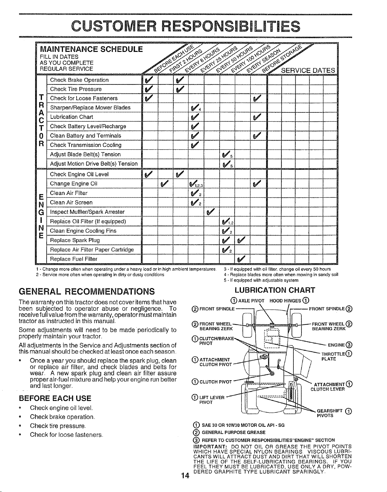
1- Change more olten when operating under a heavy load or in high ambient temperatures 3 - If equipped with oil It!tar, change oil every 50 hours
2 - Service more otten when operating in dirly or dusty conditions
GENERAL RECOMMENDATIONS
The warranty on this tractor does not cover items that have
been subjected to operator abuse or negligence. To
receive full value from the warranty, operator must maintain
tractor as instructed in this manual.
Some adjustments will need to be madeperiodically to
properly maintain your tractor..
Al! adjustments in the Service and Adjustments section of
this manual should be checked at least once each season.
o Once a year you should replace the spark plug, clean
or replace air filter, and check blades and belts for
wear. A new spark plug and clean air filter assure
proper air-fuel mixture and help your engine run better
and last !onger.
@ FRONT WHEEL _ _ FRONT WHEEL @
-- BEARING ZERK 1 14 r _:_::_.
®ATTAO.MENT_ _ j _O_L_
CLUTCH PIVOT ""- __L_ 1,.,_
(_ CLUTCH PIVOT _F.....,_Z_=,,_, ""_" ATTACHMENT (_)
4 _ Replace blades more oiten when mowing in sandy soil
5 - If equipped with adjustable system
LUBRICATION CHART
(3)AXLEP,VOTHOOeHINGES(i:)
BEFORE EACH USE
, Check engine oil level..
• Check brake operation..
, Check tire pressure.
° Check for loose fasteners.
P,vo_ [1______ _eEARS.,_®
(_) SAE 30 OR 10W30 MOTOR OIL API - SG
® GENERAL PURPOSE GREASE
® REFER TO CUSTOMER RESPONSIBiLITtES"ENGtNE" SECTION
IMPORTANT: DO NOT OIL OR GREASE THE PWOT POINTS
WHICH HAVE SPECIAL NYLON BEARINGS VISCOUS LUBRI-
CANTS WILL ATTRACT DUST AND DIRT THAT WILL SHORTEN
THE LIFE OF THE SELF-LUBRICATING BEARINGS, IF YOU
FEEL THEY MUST BE LUBRICATED, USE ONLY A DRY, POW-
DERED GRAPHITE TYPE LUBRICANT SPARINGLY.
14
U BEARING ZERK -
7"--
CLUTCH LEVER
PIVOTS

i .................... iiiiiiii,, i===1 ........................
CUSTOMER
,L , ,,i,iii, IIIIII III
RESPONSIBILITIES
TRACTOR
Always observe safety rules when performing any mainte-
nance.
BRAKE OPERATION
If tractor requires more than six (6) feet stopping distance
at high speed in highest gear than brake must be adjusted,
(See "TO ADJUST BRAKE" in the Service and Adjust-
ments section of this manual)..
TIRES
• Maintain proper air pressure in all tires (See "PROD-
UCT SPECIFICATIONS" on page 3 of this manual).,
o Keep tires free of gasoline, oil, or insect control chemi-
cals which can harm rubber.
• Avoid stumps, stones, deep ruts, sharp objects and
other hazards that may cause tire damage..
BLADE CARE
For best results mower blades must be kept sharp, Re-
place bent or damaged blades..
BLADE REMOVAL (See Fig. 13)
o Raise mower to highest position to allow access to
blades.
• Remove hex bolt, lock washer and flat washer securing
blade°
o Install new or resharpened blade with trailing edge up
towards deck as shown..
• Reassemble hex bolt, lock washer and fiat washer in
exact order as shown°
° Tighten bolt securely (30-35 Ft. Lbs. torque).
IMPORTANT: BLADE BOLT iS GRADE 8 HEAT TREATED
MANDREL
ASSEMBLY
i ii1,11111 i iii iiiiiiiiiiiiiiiii
TO SHARPEN BLADE (See Fig. 14)
Care should be taken to keep the blade batanced_ An
unbalanced blade will cause excessive vibration and even-
tual damage to mower and engine.
• The blade can be sharpened with a file or on a grinding
wheel. Do not attempt to sharpen while on the mower.
= To check blade balance, you will need a 5/8" diameter
steel bolt pin, or a cone balancer. (When using a cone
balancer, follow the instructions suppled with bal-
ancer).
• Slide blade on to an unthreaded portion of the steel bolt
or pin and hold the bolt or pin parallel with the ground,
If blade is balanced, it should remain in a horizontal
position_ If either end of the blade moves downward,
sharpen the heavy end until the blade is balanced.
NOTE: Do not use a nai! for balancing blade. The lobes of
the center hole may appear to be centered, but are not°
CENTER HOLE
BLADE
5/8"BOLT
OR PIN
FIG. 14
BATTERY (See Fig. 15)
Your tractor has a battery charging system which is suffi-
cient for normal use. However periodic charging of the
battery with an automotive charger will extend its fe.
• Acid solution level in each battery cell should be even
with bottoms of vent wells.. Add only distilled oriron free
water if necessary,, Do not overfill.
. Keep batteryand terminals clean,.
° Keep battery bolts tighL
o Keepvent capstight and small vent holes in caps open.
• Recharge at 6 amperes for 1 hour,,
"A GRADE 8 HEAT TREATED BOLT CAN BE IDENTIFIED BY
SIX LINES ON THE BOLT HEAD
FIG. 13
CUT AWAY VIEW
I IjVENT°AP
WELL
BATTERY
CELL ACID
LEVEL
FIG. 15
15

i= ==,= iii1,,,=
CUSTOMER
TO CLEAN BATTERY AND TERMINALS -
Corrosion and dirt on the battery and terminals can cause
the battery to "leak" power°
, Open battery box door.
• Disconnect BLACK battery cable first then RED bat-
tery cable and remove battery from tractor.
• Wash battery with solution of four tablespoons of
baking sodatoonegallon ofwater Becareful nottoget
the soda solution into the cells.
- Rinse the battery with plain water and dry,
o Clean terminals and battery cable ends with wire brush
until bright
- Coat terminals with grease or petroleum jeliyo
- Reinstall battery (See "INSTALL BATTERY" in the
Assembly section of this manual).
RESPONSIBmLITmES
1. , =u uu,uu ........... _ ...................................
V- BELTS
Check V-Belts for dete rioration and wear after 100 hours of
operation, Replace if necessary. The belts are not adjust-
able. Replace belts if they begin to slip from wear.
TRANSAXLE COOLING
Keep transaxle free from build_up of dirt and chaff which
can restrict cooling.
Check the crankcase oil leveI before starting the engine
and after each eight (8) hours of continuous use° Tighten
oil fill cap/dipstick securely each time you check the oil
level.
TO CHANGE ENGINE OIL (See Fig. 16 and 17)-
Determine temperature range expected before oi! change.
All oil must meet API service classification SG.
• Be sure tractor is on level surface_
o Oil wilt drain more freely when warm.
- Catch oil in a suitable container.
• Remove oil fill dipstick. Be careful not to allow dirt to
enter the engine when changing oil.
o Remove drain plug,
, After oil has drained completely, replace oil drain plug
and tighten securely,
o Refill engine with oil through oil fill dipstick tube. Pour
slowly. Do not overfill For approximate capacity see
"PRODUCT SPECIFICATIONS" on page 3 of this
manual
° Use gauge on oil fill dipstick for checking level Be sure
dipstick cap is tightened securely for accurate reading.
Keep oil at "FULL" line on dipstick.
ENGINE
LUBRICATION
Only use high quality detergent oil rated with API service
classification SG Select the oil's SAE viscosity grade
according to your expected operating temperature.
SAE VISCOSITY GRADES
• 1
_F -20° 0_ 302 32" 40 _ 60 _ 80 _ _00 _
°c 40° .27_ 4;° co loo 2o° _oo 4oo
TEMPERATURE RANGE ANTICIPATED BEFORE NEXT OIL CHANGE
NOTE: Although muttiviscosity oils (5W30, 10W30 etc.)
improL,e starting in cold weather, these mufti-viscosity oils
will result in increased oil consumption when used above
32°F. Check your engine oil level more frequently to avoid
possible engine damage from running low on oil.
Change the oil after the first two hours of operation and
every 25 hours thereafter or at least once a year if the
tractor is not used for 25 hours in one year.
OIL FILL
DIPSTICK
FIG. 16
PLUG
TO REMOVE
FIG. 17
16
 Loading...