

Craftsman 917256890 Owner’s Manual

SEARS
CRRFr,SM
MODEL NUMBER 917.256890 OWNER'SMANUAL
oAssembly
Operation
Customer Responsibilities
Service and Adjustments
Repair Parts
CAUTION: Read and follow all safety rules and instructions before operating this equipment.
FOR CONSUMER ASSISTANCE HOT LINE, CALL THIS TOLL FREE NUMBER: !-800-659-5917
i"rl ............................................ II "111
Safe Operation Practices for Ride-On Mowers
IMPORTANT: THIS CUTTING MACHINE IS CAPABLE OF AMPUTATING HANDS AND FEET AND THROWING OBJECTS.
FAILURE TO OBSERVE THE FOLLOWING SAFETY INSTRUCTIONS COULD RESULT IN SERIOUS INJURY OR DEATH.
SAFETY RULES
A
I, GENERAL OPERATION
• Read, understand, and follow alt instructions in the manual
and on the machine before starting.
, Only allow responsible adults, who are familiar with the
instructions, to operate the machine.
• Clear the area of objects such as rocks, toys, wire, etc.,
which could be picked up and thrown by the blade.
• Be sure the area isclear of otherpeopte before mowing. Stop
machine if anyone enters the area.
• Never carry passengers,
° Do not mow in reverse unless absolutely necessary, Always
lookdown and behind before and while backing.
• Be aware of the mower discharge direction and do not point
it at anyone. Do not operate the mower without either the
entire grass catcher or the guard in place.
• Slow down before turning.
• Never leave a running machine unattended, Always turn off
blades, set parking brake, stop engine, and remove keys
before dismounting,
• Turn off blades when not mowing.
° Stop engine before removing grass catcher or unclogging
chute.
o Mow only in daylight or good artificial light.
° Do not operate the machine while under the influence of
alcohol or drugs.
• Watch for traffic when operating near or crossing roadways.
• Use extra care when loading or unloading the machine into
a trailer or truck.
II. SLOPE OPERATION
Slopes are a ma or factor related to toss-of-control and tipover
acc dents, wh ch can resu t n severe injury or death, Alt slopes
require extra caution. If you cannot back up the slope or ifyou fee!
uneasy on it, do not mow it.
DO:
• Mow up and down siopes, not across.
• Remove obstacles such as rocks, tree limbs, etc.
• Watch for holes, ruts, or bumps. Uneven terrain could
overturn the machine. Tall grass can hide obstacles,
• Use slow speed. Choose a low gear so that you will not have
to stop or shift while on the slope.
• Follow the manufacturer's recommendations for wheel
weights or counterweights to improve stability.
, Use extra care with g'rass catchers or other attachments.
These can change the stability of the machine.
, Keep all movement on the elopes slowand gradual. Do not
make sudden changes in speed or direction.
• Avoid starting or stopping on a slope, if tires lose traction,
disengage the blades and proceed slowty straight down the
slope.
DO NOT:
• Donotturnonslopesunlessnecessary, andthen, turnsiowly
and gradually downhill, if possible,
° Do not mow near drop-offs, ditches, or embankments, The
mower could suddenly turn over if a wheel is over the edge
of a cliff or ditch, or if an edge caves in;
, Do not mow on wet grass. Reduced traction could cause
sliding,
• Do not try to stabilize the machine by putting your foot on the
ground,
• Do not use grass catcher on steep slopes,
II1. CHILDREN
Tragic accidents can occur if the operator is not alert to the
presence of children. Children are often attracted to the machine
and the mowing activity. Never assume that children will remain
where you last saw them.
• Keep children out of the mowing area and under the watchful
care of another responsible adult.
• Be alert and turn machine off if children enter the area.
° Before and when backing, look behind and down for small
children,
• Never carry children, They may fall off and be seriously
injured or interfere with safe machine operation.
- Never allow children to operate the machine.
• Use extra care when approaching blind corners, shrubs,
trees, or other objects that may obscure vision.
iV. SERVICE
• Use extra care in handling gasoline and other fuel& They are
flammable and vapors are explosive.
Use only an approved container.
Never remove gas cap or add fuel with the engine
running. Allow engine to cool before refueling. Do not
smoke.
Never refuel the machine indoors.
Never store the machine or fuel container inside where
there is an open flame, such as a water heater.
o Never run a machine inside a closed area.
• Keep nuts and bolts, especially blade attachment bolts, tight
and keep equipment in good condition.
• Never tamper with safety devices. Check their proper
operation regularly,
° Keep machine free of grass, leaves, or other debris build-up.
Clean oil or fuel spillage, Allow machine to cool before
storing.
• Stop and inspect the equipment if you strike an object.
Repair, if necessary, before restarting.
• Never make adjustments or repairs with the engine running_
• Grass eatchercomponents are subject to wear, damage, and
deterioration, which could expose moving parts or allow
objects to be thrown. Frequently check components and
replace with manufacturer's recommended parts, when nec-
essary,
• Mower blades are sharp and can cut. Wrap the blade(s) or
wear gloves, and use extra caution when servicing them.
• Check brake operation frequently. Adjust and service as
required. , .........
Look for this symbol to point out impor-
CAUTION!!! BECOME ALERT!!! YOUR
tant safety precautions. It means
SAFETY IS INVOLVED.
ilnl i,nnnn i i i,,,nl i,in
,,i,ilU,nil i nnl, _ ,,
CAUTION: A|ways disconnect spark plug
spark plug in order to prevent accidental
wire and place wire where it cannot contact
starting when setting up, transporting,
adjusting or making repairs.
,unlnn H,,i,,ll ,i i i,, nn
iiiin unnnl
WARNING A
The engine exhaust from this product con-
tains chemicals known to the State of Califor-
nia to cause cancer, birth defects, or other
reproductiv e harm. ..............
2

CONGRATULATIONS on your purchase of a Sears
Tractor. It has been designed, engineered'and manufac-
tured to give you the best possible dependability and
performance.
Should you experience any problem you cannot easily
remedy, please contact your nearest Sears Authorized
Service Center/Department: We have competent, well-
trained technicians and the proper tools to service or repair
this tractor.
Please read and retain this manual. The instructions will
enable you to assemble and maintain your unit properly.
Always observe the "SAFETY RULES".
MODEL
NUMBER 917.256890
SERIAL
NUMBER
DATE OF PURCHASE
THE MODELAND SERIAL NUMBERS WILL BE FOUND
ON A PLATE UNDER THE SEAT.
YOU SHOULDRECORD BOTH SERIAL NUMBER AND
DATE OF PURCHASE AND KEEP IN A SAFE PLACE
FOR FUTURE REFERENCE.
MAINTENANCE AGREEMENT
A Sears Maintenance Agreement is available on this prod-
uct, Contact your nearest Sears store for details,
CUSTOMER RESPONSIBILITIES
- Read aria observe the safety rules,
. Follow a regular schedufe in maintaining, cadng for and
using your tractor,
• Follow the instructions under "Customer Responsibili-
ties" and "Storage" sections of troisowner's manuai
PRODUCT SPECIFICATIONS
HORSEPOWER: 15.5
GASOLINE CAPACITY t .25 GALLONS
AND TY_PE: UNLEADED REGULAR
OIL TYPE (API-SF/SG): SAE 30 (above 32'_F)
SAE 5W-30 (below 32°F)
OtL CAPACITY: 3 PINTS
SPARK PLUG: CHAMPION RJt9LM
(GAP: .030")
VALVE CLEARANCE: INTAKE: .005" - .007"
EXHAUST: .009"- ,0tl"
GROUND SPEED (MPH): FORWARD: 5,7 '
REVERSE: 2.7
TIRE PRESSURE: FRONT: 14 PSi
REAR: 12 PSt
CHARGING SYSTEM: 3 AMPS BATTERY
5 AMPS HEADLIGHTS
BATTERY: AMPiHR: 25
MIN. CCA: 190
CASE SIZE: U1R
BLADEBOLT TORQUE: 30-35 FT. LBS. ]
WARNING: This tractor is equipped with an internal
combustion engine and should not be used on or near any
unimproved forest-covered brush-covered or g'ass-cov-
ered land unless the engine's exhaust system is equtpped
with aspark arrester meeting applicable local or state laws
(if any). If a spark arrester is used. it should be maintained
in effective working order by the operator,
In the state of California the above is required by Iaw
(Section 4442 ol the California Public Resources Code).
Other states may have similar taws. Federal laws apply on
federal lands. A spark arrester for the muffler is available
through your nearest Sears Authorized Service Center/
Department (See REPAIR PARTS section ofthis manual!.
/
LIMITED TWO YEAR WARRANTY ON CRAFTSMAN RIDING EQUIPMENT
Fortwo (2) yearsfrom the date of purchase,if this Craftsman RidingEquipment ismaintained lubricated and tuned upaccording
to the instructions in the owner's manual Sears will repairor replace, free of charge, any parts found to be defective in material
or workmanship,
This Warranty does not cover:
o
Expendable items which become worn during normai use such as blades spark plugs, air cfeaners, belts, etc.
q
Tire replacement or repair caused by punctures from outside objects, such as nails, thorns, stumps, or g_ass.
Re_airs necessary because of operator abuse negligence, improper storage or accident or the failure to maintain the
equipment according to the instructions contained in the owner's manual
Riding equipment used for commercial or rental purposes.
LIMITED 90 DAY WARRANTY ON BATTERY
For ninety (90) days from date of purchase, if any battery included with this riding equipment proves defective in material or
workmanship andour testing determines the batterywitlnot hoId acharge, Searswill replacethe batten:/at no charge,
IN-HOME WARRANTY SERVICE ON YOUR CRAFTSMAN RIDING EQUIPMENT IS AVAILABLE AT NO-CHARGE FOR 30
DAYS FROIV THE DATE OF PURCHASE. PLEASE CONTACT YOUR NEAREST SERVICE CENTER. AFTER 30 DAYS
FROM THE DATE OF PURCHASE WARRANTY SERVICE IS AVAILABLE BY TAKING YOUR CRAFTSMAN RIDING EQUIP-
MENT TO YOUR NEAREST SEARS SERVICE CENTER. (IN-HOME WARRANTY SERVICE WILL STILL BE AVAILABLE
AFTER 30 DAYS FROM THE DATE OF PURCHASE BUT A STANDARD TRIP CHARGE WILL APPLY.) THIS WARRANTY
APPLIES ONLY WHILE TH S PRODUCT IS IN THE UNITED STATES.
-his Warranty gives you specific legal rights, and you may also have other rights which may vary from state to state
SEARS, ROEBUCK AND CO., D/817 WA, HOFFMAN ESTATES, IL 60179
3
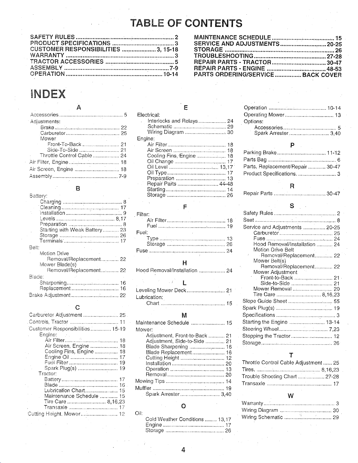
TABLE OF CONTENTS
SAFETY RULES ............................................................ 2
PRODUCT SPECIFICATIONS ...................................... 3
CUSTOMER RESPONSIBILITIES ..................... 3, 15-18
WARRANTY .................................................................. 3
TRACTOR ACCESSORIES .......................................... 5
ASSEMBLY ................................................................ 7-9
OPERATION ........................................................... 10-14
iNDEX
A
Accessories ........................................... 5
Adjustments:
Brake ......................................... 22
Carburetor .................................... 25
Mower
Front-To-Back ......................... 21
Side-To-Side ........................... 21
Throttle Control Cable .................. 24
Air Filter. Engine .................................. 18
_r Screen. Engine .............................. t8
Assembly ............................................ 7-9
B
Battery:
Charging ........................................ 8
CEeanmg ...................................... 17
ns[allation ...................................... 9
Levels ....................................... 8.17
Preoaration ................................... 8
Starting with Weak Battery ........... 23
Storage ........................................ 26
Terminais ................................... I7
Bett:
Motion Drive
Remova{iReplacement ............ 22
4ower Blade(s)
Removal/Replacement ............ 22
Bade:
Sharpening ................................... 16
Replacemeni ................................ 16
Brake Adiustment ................................ 22
C
Carburetor Adjustment ..................... 25
ControJs. Tractor ................................. 11
Customer Responsibilities .............. 15-19
Engine:
A_r Filter ........... :...................... 18
Air Screen Engine .................. t8
Cooling Fins, Engine ................ 18
Engine Oil ................................ 17
Fuel Fitter ................................ 19
Soark Plug(s) ........................... I9
Tractor:
Battery ..................................... 17
Bla:_e........................................ 16
Lubrication Chart ...................... t5
Maintenance Schedule ............ 15
Tire Care ......................... 8,16,23
Transaxte ................................. 17
SuttJng Height, Mower ......................... 12
Electdcak
qterlocks and Relays ................... 24
Schematic .................................... 29
Wiring Diagram ............................ 30
Engine:
Air Filter ....................................... 18
Air Screen .................................... 18
Cooling Fins, Engine .................... 18
OiJ Change ................................. 17
Oil Lever .................................. 13.17
Oil Type ........................................ 17
Preparation .................................. 13
Repair Parts ............................ 44-48
Starting ......................................... 14
Storage ........................................ 26
Filter:
Air Filter ........................................ 18
Fue} .............................................. 19
Fuel:
Type ............................................ 13
Storage ........................................ 26
Fuse .................................................... 24
Hood Removal/installation .................. 24
Leveling Mower Deck .......................... 21
Lubrication:
Chart ............................................ 15
Maintenance Schedule ....................... 15
Mower:
Adiustment. Front-to-Back ........... 21
Adiustment, Side-to-Side ............. 21
Bfade Sharpening ..................... 16
Blade Replacement ...................... t 8
Cut[ing Height .............................. 12
installation .................................... 20
Operation ..................................... !3
Removal ....................................... 20
Mowing T@s ........................................ 14
Muffler ................................................. 19
Spark Attester ........................... 3,40
Oil:
Cold Weather Conditions ........ 13.17
Engine ......................................... !7
Storage ........................................ 26
MAINTENANCE SCHEDULE ...................................... 15
SERVICE AND ADJUSTMENTS ............................ 20-25
STORAGE ................................................................... 26
TROUBLESHOOTING ............................................ 27-28
REPAIR PARTS - TRACTOR ................................. 30-47
REPAIR PARTS - ENGINE .................................... 48-53
PARTS ORDERING/SERVICE ................ BACK COVER
E
Operation ....................................... 10-t4
Operating Mower ................................. 13
Options:
Accessories ................................... 5
Spark Arrester ........................... 3,40
P
Parking Brake ............................ 11-12
Parts Bag .............................................. 6
Parts. Replacement'Repair ............ 30-47
Product Specifications ........................... 3
R
Repair Parts ................................... 30-47
F
Safety Rules .......................................... 2
Seat ..................................................... 8
Service and Adjustments ............... 20-25
Carburetor .................................. 25
Fuse ............................................. 24
Hood Removal/installation ........... 24
Motion Drive Belt
_emova_/Replacement ............ 22
H
L
M
O
Mower Bett(s)
Removal/Replacement ............ 22
Mower Adjustment
Front-to-Back ........................ 21
Side-to-Side ............................ 21
Mower Removal ........................... 20
Tire Care .............................. 8,16,23
Slope Guide Sheet .............................. 55
Spark Plug(s) ...................................... 19
Specifications ....................................... 3
Starting the Engine ....................... 13q4
Steering Wheel .............................. 7,23
Stopping the Tractor ........................... 12
Storage ................................................ 26
Throttle Control Cable Adjustment ..... 25
Tires ............................................ 8,16.23
Trouble Shooting Chart .................. 27-28
Transaxle ............................................ I7
Warranty ................................................ 3
Wiring Diagram .................................. 30
Wiring Schematic ................................ 29
S
T
W
4
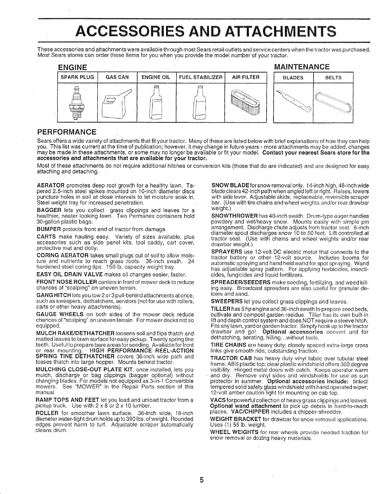
ACC RIES AND ATTACHMENTS
These accessories and attachments were available through most Sears retail outlets and service centers when the tractorwas purchased,
Most Sears stores can order these items for you when you provide the model number of your tractor.
ENGINE
SPARK PLUG : AIR FILTER BELTSGAS CAN ENGINE OIL
FUEL STABtUZER
MAINTENANCE
BLADES
PERFORMANCE
Sears offers a wide variety of attachments that fit your tractor. Many of these are tisted below with brief explanations of how they can help
you. This list was current at the time of publication: however, it may change infuture years - more attachments may be added, changes
may be made in these attachments, or some may no longer be available or fit your model. Contact your nearest Sears store for the
accessories and attachments that are available for your tractor.
Most of these attachments do not require additional hitches or conversion kits (those that do are indicated) and are designed for easy
attaching and detaching.
AERATOR promotes deep root growth for a healthy lawn. Ta-
oered 2.5-inch steel spikes mounted on 10-inch diameter discs
puncture holes in soil at close intervals to let moisture soak in_
SteeI weight tray for increased penetration.
BAGGER lets you colfect grass clippings and leaves for a
healthier nearer looking lawn, Two Permanex containers hold
30-gallon plastic bags.
BUMPER protects front end of tractor from damage.
CARTS make hauling easy, Variety of sizes available plus
accessories such as side panel kits tool caddy, cart cover.
protective mat and dolly,
CORING AERATOR takes small Plugs out Ofsoil to allow mois-
ture and nutrients to reach grass roots 364rich swath. 24
hardened steel coring tips, 150 tb. capae=ty welght tray,
EASY OIL DRAIN VALVE makes oil changes eas_er, faster.
FRONT NOSE ROLLER canters in front of mower deck to reduce
chances of "sca 3ing" on uneven terrain.
GANG HITCH lets you tow 2or3 pull-behind attachments at once.
such as sweepers, dethatchers, aerators {not for use with rollers,
carts or other heavy attachments_.
GAUGE WHEELS on both sides of the mower deck reduce
chances of "scalping" on uneven terrain. For mower decks not so
equipped.
MULCH RAKE/DETHATCHER loosens soil and flips thatch and
matted leaves to lawn surface for easy pickup. Twenty spring tine
teeth. Useful to prepare bare areasfor seeding, Availabfe for front
or rear mounting_ HIGH PERFORMANCE REEL-ACTION
SPRING TINE DETHATCHER covers 36-inch wide path and
tosses thatch into large hopper. Mounts behind tractor.
MULCHING CLOSE-OUT PLATE KIT, once installed, lets you
mulch, discharge or bag clippings (bagger optiona}) without
changing blades. For models not equipped as 3-in-1 Convertible
mowers. See "MOWER" in the Repair Parts section of this
manual
RAMP TOPS AND FEET let you load and unload tractor from a
pickup truck, Use with 2 x 8 or 2 _:10 lumber.
ROLLER for smoother lawn surface. 36-inch wide, 18-inch
diamete rwater-tight drum holds up to 390 Ibs. otweight. Rounded
edges prevent harm to tuff. Adjustable scraper automatically
cleans drum. '
SNOW BLADE forsnow removalonly, 14-inch high. 48-inch wide
blade clears 42-inch path when angled left orright. Raises. lowers
with side lever, Adjustable skids; replaceable, reversible scraper
bar. (Use with tire chains and wheel weights and/or rear drawbar
weight.)
SNOWTHROWER has 40-inch swath. Drum-type auger handtes
powdery and wet/heavy snow. Mounts easily with simple pin
arrangement. Discharge chute adjusts from tractor seat. 6-inch
diameter spout discharges snow 10 to 50 feet. Lift controlled at
tractor seat. (Use with cr_aLnsand wheel weightS and/or rear
drawbar we=ght.)
SPRAYERS use 12-volt DC etectric motor that connects to the
tractor battery or other 12-volt source, Includes booms for
automatic spraying and hand held wand for spot spraying, Wand
has adjustable spray pattern. For applying herbicides, insecti-
cides, fungicides and tic Jid fertilizers
SPREADER/SEEDERS make seeding, fertilizing, and weed kill-
ing easy. Broadcast spreaders are also useful for granular de-
icers and sand.
SWEEPERS let you collect grass clippings and leaves.
TILLER has 5 hp engine and36-inch swath to prepare seed beds,
cultivate and compost garden residue. Tiller has its own built-in
lift and depth control system and does NOT require a sleeve hitch.
Fits any lawn, yard or garden tractor. Simply hook up to the tractor
drawbar and go! Optional accessories convert unit for
dethatching, aerating, hilling...without tools.
TIRE CHAINS are heavy duty; closely spaced extraqarge cross
Iinks give smooth ride, outstanding traction.
TRACTOR CAB has heavy duty vinyl fabric over tubular steel
frame, ABS plastic top; clear plastic windshield offers 360 degree
visibility. Hinged metal doors with catch. Keeps operator warm
and dry. RemOve vinyi sides and windshields for use as sun
protector in summer. Optional accessories include: tinted/
tempered solid safety glass windshield with hand operated wiper;
12-volt amber caution light for mounting on cab top.
VACS for powerful collection of heavy grass clippings and leaves.
Optional wand attachment to pick up debris in hard-to-reach
places. VACICHIPPER includes a chipper-shredder,
WEIGHT BRACKET for drawbar for snow remow_ applications.
Uses (l) 55 lb. weight.
WHEEL WEIGHTS for rear wheels provide needed traction for
snow removal or dozing heavy materials,

CONTENTS OF HARDWARE PACK
. . _ ..... =
Parts Bag contents shown full size
/ ".
/ \
O (2) Sheet
(t) Locknut 3/8-24
(t) 2-3/8" Diameter Washer
Metal
I Screws
#10-16 x 1/2
Parts packed separately in carton
Seat
Video
Cassette
Steering
Wheel
Steering
Boot
' Shoulder Bolt 5/16-18 (!) Hex Bolt I/2ol 3 x 1
/ \
(1) Lock Washer 1/2
1) Washer !7/32 x !-3/16 x 12 Gauge
{2) Hex Bolts 1/4-20 x 3/4
(2) Hex Nuts 1/4-20
I f
Manual
Parts bag contents not shown full size
Steering Wheel Wheel
Adapter Insert
Parts Bag
Steering
(2) Lock Washers !/4
2_ Washers 9/32 x 5/8 x 16 Gauge
(2) Keys
Slope Sheet

ASSEMBLY
Your new tractor has been assembled at the factory with exception of those parts left unassembled for shipping purposes.
To ensure safe and proper operation of your tractor all parts and hardware you assemble must be tightened securely. Use
the correct tools as necessary to insure proper tightness.
TOOLS REQUIRED FOR ASSEMBLY
A socket wrench set will make assembty easier. Standard
wrench sizes are listed.
(1) 5/16" wrench
(2) 7/16" wrenches
(1) l/2" wrench
(1) 3/4" wrench
When "ight and left hand are mentioned in this manual, it
means when you are in the operating position (seated
behind the steering wheel).
TO REMOVE TRACTOR FROM CARTON
UNPACK CARTON
- Remove all accessible loose parts and parts cartons
from carton (See page 6).
- Cut along ines on carton, from top to bottom, all four
corners of carton and lay panels flat.
- Check for any additional loose parts or cartons and
remove.
(t) 9/t6" wrench
Tire pressure gauge
Utility knife
STEERING
BUSHING
SCREW
BEFORE ROLLING TRACTOR OFF SKID
ATTACH STEERING WHEEL (See Fig. 1)
- Slide the steering bushing over the steeling shaft.
, Raise steering shaft forward until screw holes in dash
line up with steering bushing. Install two (2) sheet
metal screws and tighten securety.
, Position steering boot over steering shaft.
• Align tabs of steering boot over slots and hole in dash
and push down to secure.
• Slide steering wheel adapter onto upper steering shaft.
- Position front wheels of the tractor so they are pointing
straight forward.
• Position steering wheel so cross bars are horizontal
(left to right) and slide onto adapter.
, Assemble large fiat washer and 3/8-24 hex iocknut and
tighten securely.
= Snap insert into center of steering wheel.
, Remove protective plastic from tractor hood and grill.
IMPORTANT: CHECK FOR AND REMOVE ANY
STAPLES tN SKID THAT MAY PUNCTURE TIRES WHERE
TRACTOR IS TO ROLL OFF SKID.
SLOT
FIG. 1
TO ROLL TRACTOR OFF SKID (See Opera-
tion section for location and function of con-
trois)
• Press lift lever plunger and raise attachment lift lever to
its highest position.
- Release parking brake by depressing clutch/brake
pedal.
" Place freewheel control in freewheeling position to
disengage transmission (See "TO TRANSPORT" n
the Operation section of this manual).
° Roll tractor backwards off skid.
• Remove banding holding discharge guard up against
tractor.
AS
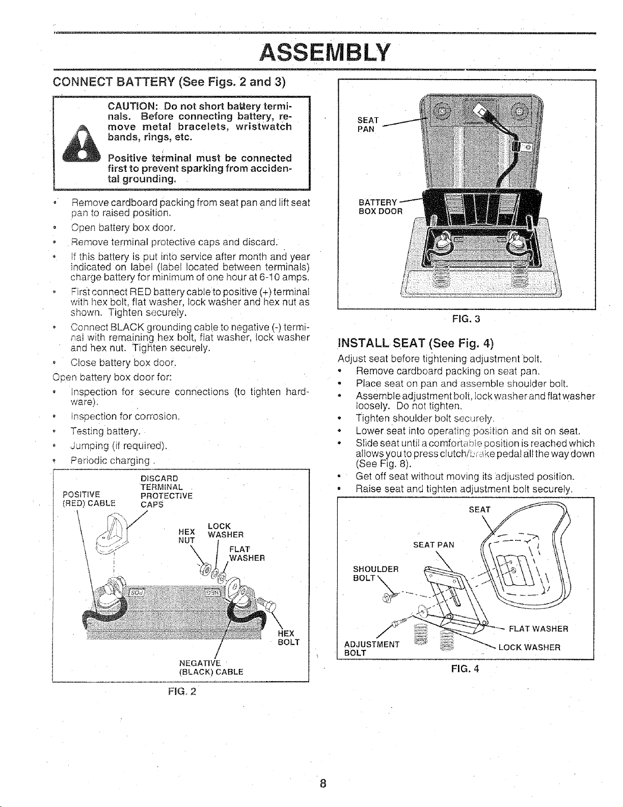
CONNECT BATTERY (See Figs. 2 and 3)
CAUTRON: Do not short battery termi-
nals. Before connecting battery, re-
bands, rings, etc.
move metal bracelets, wristwatch
Positive terminal must be connected
first to prevent sparking from acciden-
tal grounding.
iVlBLY
SEAT
PAN
° Remove cardboard packing from seat pan and lift seat
pan to raised position.
, Csen battery box door.
Remove terminal protective caps and discard.
f this battery is put into service after month and year
indicated on label (label located between termina s)
charge battery for minimum of one hour at 6-I0 amps.
First connect RED battery cable to positive (+) terminai
with hex bolt. flat washer lock washer and hex nut as
ShOWn Tighten securely.
Connect BLACK grounding cable to negative (-) termi-
na_with remaining hex bolt, fiat washer, lock washer
and hex nut. Tigr_ten securely.
o Close battery box door.
Open battery box door for:
o nseection for secure connections (to tighten hard-
wareF
o nspection for corrosion.
Testing battery.
oumping (if required).
Periodic charging.
DISCARD
POSITIVE PROTECTIVE
(RED_ CABLE CAPS
!,...... _.S NUT
TERMINAL
LOCK
WASHER
FLAT
WASHER
BOX DOOR
FIG. 3
INSTALL SEAT (See Fig. 4)
Adjust seat before tightening adjustment bolt.
- Remove cardboard packing on sea_ pan.
• Place seat on pan and assemble shouIder bolt.
- Assemble adjustment bolt. Iock washer and flat washer
Ioosely. Do not tighten.
• Tighten shoulder bolt sec_Jrely.
• Lower seat into operating poseidonand sit on seat.
° Slide seat until a comfortable position is reached which
allows Vouto press clutch/L, ;_kepedal all the way down
(See Fig. 8).
• Get off seat without moving its adjusted position.
, Raise seat and tighten adjustment bolt securely.
SEAT
\
SEAT PAR
SHOULDER
NEGATIVE
(BLACK) CABLE
FIG, 2
BOLT _.
HEX
!
BOLT
/
ADJUSTMENT
BOLT
FLAT WASHER
LOCK WASHER
FIG. 4
ASSEMBLY
CHECK TIRE PRESSURE
The tires on your tractor were overinflated at the factory' for
shipping purposes. Correct tire pressure is important for
best cutting performance.
• Reduce tire pressure to PSi shown in "PRODUCT
SPECIFICATIONS on page 3 of this manual.
CHECK DECK LEVELNESS
For best cutting results, mower housing should be properly
leveled. See "TO LEVEL MOWER HOUSING" in the
Service and Adjustments section of this manual.
CHECK FOR PROPER POSITION OF ALL
BELTS
See the figures that are shown for replacing motion and
mower blade drive belts in the Service and Adjustments
section of this manual. Verify that the belts are routed
correctly.
CHECK BRAKE SYSTEM
After you learn _ow to operate your tractor, check to see
that the brake is properly adjusted. See "TO ADJUST
BRAKE" n the Service and Adjustments section of this
manual.
,/CHECKLIST
BEFORE YOU OPERATE AND ENJOY YOUR NEW
TRACTOR, WE WISH TO ASSURE THAT YOU RECEIVE
THE BEST PERFORMANCE AND SATISFA C TION FROM
THIS QUALITY PRODUCT.
PLEASE REVIEW THE FOLLOWING CHECKLIST,"
,/ All assembly instructions have been completed.
,/ No remaining loose parts in carton.
¢" Batteryis properly prepared and charged. (Minimum
1 hour at 6 amos).
z" Seat is adjusted comfortably and tightened securely.
,/ All tires are properly inflated. (For shipping purposes,
the tires were overinflated at the factory).
,/ Be sure mower deck is properly leveled side-to-side/
front-to-rear for best cutting resufts. (Tires must be
properly inflated for leveling).
,/ Check mower and drive belts. Be sure they are routed
properly around pulleys and inside all bett keepers.
€" Checkwiring. See that all connections are stilt secure
and wires are properly clamped.
,/ Before driving tractor, be sure freewhee; control is in
drive position.
WHILELEARNING HOWTO USE YOUR TRACTOR. PAY
EXTRA ATTENTION TO THE FOLLOWING IMPORTANT
ITEMS:
z" Engine oil is at proper level.
¢" Fuel tank is filled with fresh, c[eam regular unleaded
gasoline.
v" Become familiar with al controls - their location and
function. Operate them before you start the engine.
v" Be sure brake system is _nsafe operating condition
v" tt is important to purge the transmission before operat-
ing your tractor for the first time. Follow proper starting
and transmission purging instructions (See 'TO START
ENGtNE" and "PURGE TRANSMISSION" in the Op-
eration section of this manual).
OPERATIO
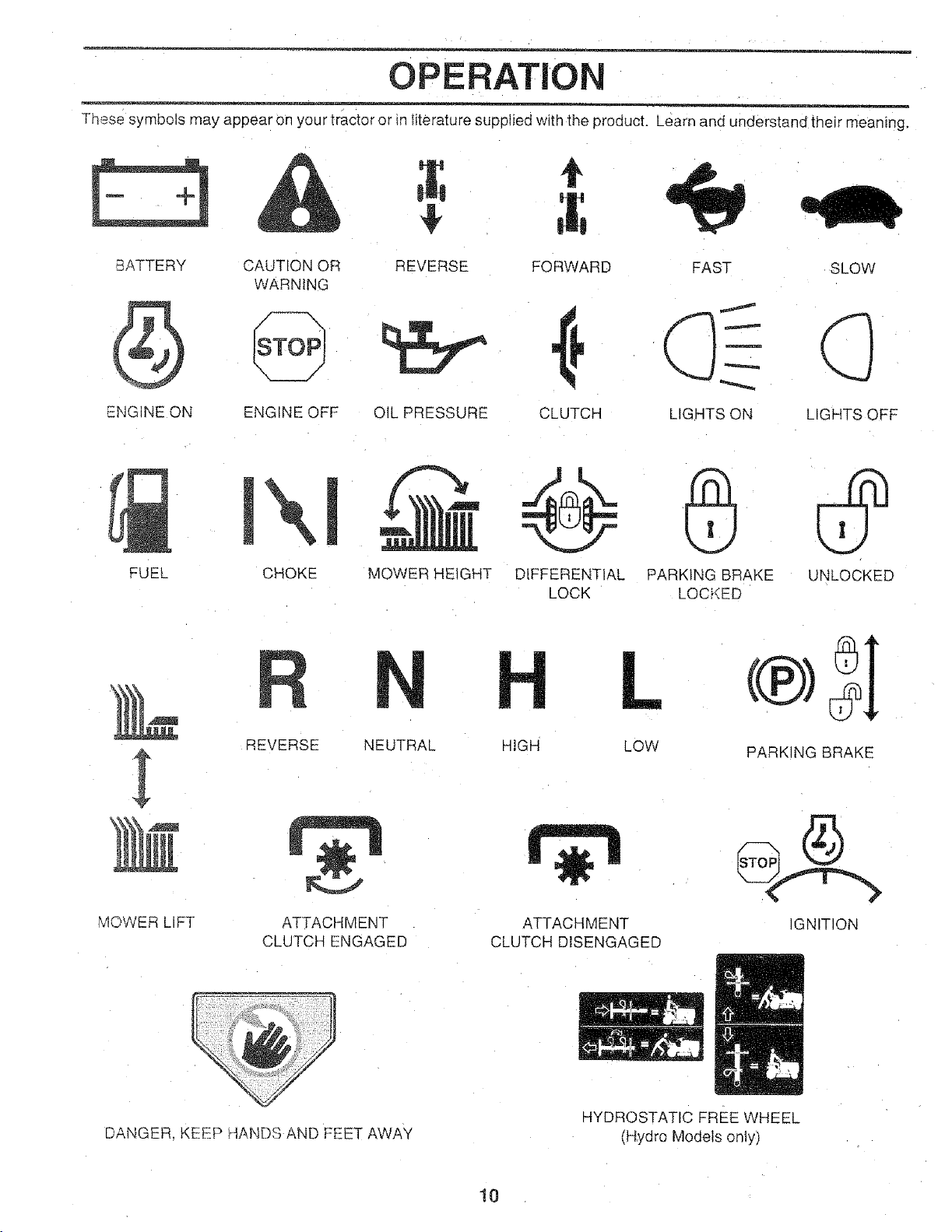
These symbols may appear on you r tractor or in literature supplied with the product. Learn and understand their meaning,
BATTERY CAUTION OR REVERSE FORWARD FAST SLOW
WARNING
ENGINE ON ENGINE OFF OIL PRESSURE CLUTCH LIGHTS ON LIGHTS OFF
FUEL
MOWER _IFT &TTACHMENT
CHOKE MOWER HEIGHT DIFFERENTIAL PARKING BRAKE UNLOCKED
REVERSE NEUTRAL HIGH
CLUTCH ENGAGED
LOCK LOCKED
LOW PARKING BRAKE
ATTACHMENT
CLUTCH DISENGAGED
IGNITION
DANGER. KEEP HANDS AND FEET AWAY
HYDROSTATIC FREE WHEEL
(Hydro Models only)
10
m
OPERATION
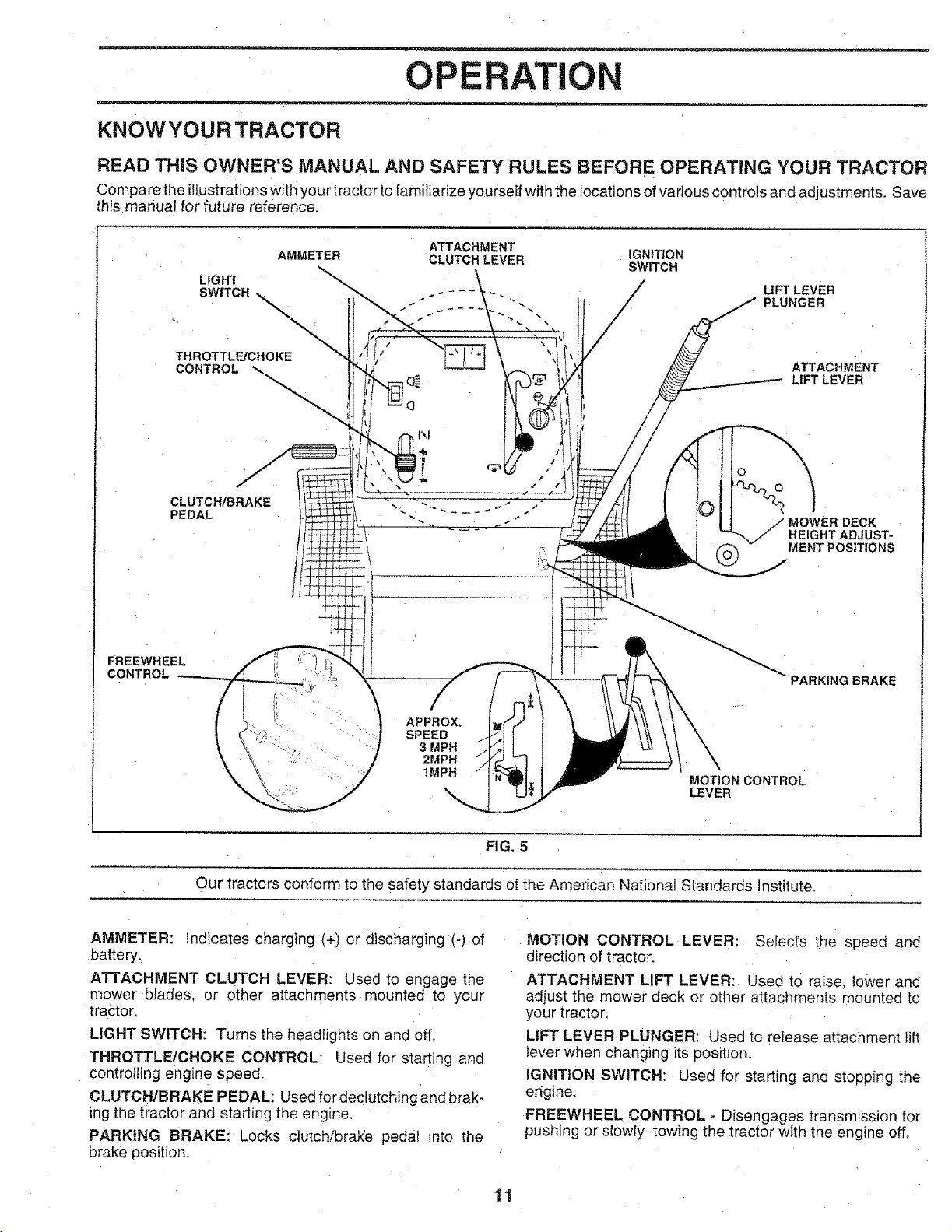
KNOWYOURTRACTOR
READ THIS OWNER'S MANUAL AND SAFETY RULES BEFORE OPERATING YOUR TRACTOR
Compare the itlustrat ons w th your tractor to fami iarize yourself with the locations of various controls and adjustments. Save
this manual for future reference,
FREEWHEEL
CONTROL
LIGHT
SWITCH
THROTTLFJCHOKE
CONTROL
CLUTCH/BRAKE
PEDAL
AMMETER CLUTCH LEVER IGNITION
ATTACHMENT
SWITCH
LIFT LEVER
PLUNGER
ATTACHMENT
LIFT LEVER
©
HEIGHT ADJUST-
_,_ MOWER DECK
MENT POSITIONS
PARKING BRAKE
APPROX.
SPEED
3 MPH
2MPH
1MPH
Our tractors conform to the safety standards of the American National Standards institute.
AMMETER: Indicates charging (+) or discharging (-) of
battery.
ATTACHMENT CLUTCH LEVER: Used to engage the
mower blades, or other attachments mounted to your
tractor.
LIGHT SWITCH: Turns the headlights on and off.
THROTTLE/CHOKE CONTROL: Usec for starting and
controlling engine speed.
CLUTCH/BRAKE PEDAL: Used fordeclutchingandbrak-
ing the tractor and starting the eng_ne
PARKING BRAKE: Locks clutchibra_e pedat into the
brake position,
MOTION CONTROL
LEVER
FIG. 5
MOTION CONTROL LEVER: Selects the speed and
direction of tractor.
ATTACHMENT LIFT LEVER: Used to raise, lower and
aajust the mower deck or other attachments mounted to
your tractor.
LIFT LEVER PLUNGER: Used to release attachment lift
lever when changing its position.
IGNITION SWITCH: Used for starting and stooping the
engine.
FREEWHEEL CONTROL - Disengages transmission for
pushing or slowly towing the tractor with the engine off.
11

OPERATION
......... . .... =
The operation of any tractor can result in foreign objects thrown into the eyes, which
can result in severe eye damage. Always wear safety glasses or eye shields while
operatingyourtractororperforming any adjustments or repairs. We recommend awide
vision safety mask over the spectacles or standard safety glasses.
HOW TO USE YOUR TRACTOR NOTE: Under cer[ain conditions when tractor is standing
TO SET PARKING BRAKE (See Fig, 6)
Your tractor is equipped with an operator presence sensing
swl[cn. When engine is running, any attempt by the
_oerator to leave the seat without first setting the Parking
brake will shut off the engine.
• Desress clutch/brake pedal into tult "BRAKE" position
and hold,
PIace 9arking brake lever in "ENGAGED" oosition and
release pressure from clutch/brake pedal. Pedal should
remain _n"BRAKE" position. Make sure parking brake
_ lSO_d_ractor secure.
THROTTLE/CHOKE
CONTFIOL\
\
\
ATTACHMENT CLUTCH LEVER
"ENGAGED" POSITION
._-.-:-_... / "DISENGAGED"
}¢ /POS,T,ON
\
"'BRAKE'
POSITION
CLUTCH/BRAKE PEDAL
"DRIVE" ROSITION
-22c_2
\
STOPPING (See Fig. 6)
MOWER BLADES -
Move attachment clutch lever to "DISENGAGED" po-
sLtion.
GROUND DRIVE-
" Deoress clutch/brake pedal into full "BRAKE" position.
o Move motion control lever to neutral (N) position,
MPORTANT: THE MOTION CONTROL LEVER DOES
NOT RETURN TO NEUTRAL (N) POSITION WHEN THE
CLUTCH/BRAKE PEDAL IS DEPRESSED.
ENGINE -
* Move throttle control to s_ow (_,) position.
NOTE: Failure to move, throttle control to slow (,,_)
posmen and allowing engine to idle before stoppng may
cause engine to "backfire",
Turn ignition key to "OFF" position and remove I_ey
A,tways remove ke_! when leaving tractor to prevent
u qauthorized use
Never u,_e choke to stop engine. 12
}/:i -:__-;>" PARKING BRAKE
f'_:,4_}}_ /"ENGAGED" POSITION
\
_-_"-x \ MOTION
CONTROL
LEVER
FIG. 6
idle with the engine running, hot engi ne exhaust gases may
cause "browning" of grass. To eliminate this Dossibility,
always stop engine when stopping tractor on grass areas.
pletely, as described above, before leaw
CAUTION: Always stop tractor com-
ing the operator's position; to empty
grass catcher, etc.
TO USE THROTTLE CONTROL (See Fig. 6)
Always operate engine at full throttle.
Operating engine at less than full throttle reduces the
battery charging rate.
- Full throttle offers the best bagging and mower perfor-
mance.
TO MOVE FORWARD AND BACKWARD
(See Fig. 6)
The direction and speed of movement _scontrolled by the
motion controi lever.
Start tractor with mohen centre lever in neutral (N)
position.
° Release parking Drake and clutch/brake pedat.
- Slowly move motion control lever to desired position.
TO ADJUST MOWER CUTTING HEIGHT
(See Fig, 5)
The position of the attachment lift lever determines the
cutting height.
- Grasp lift lever.
- Press plunger with thumb and move lever to desired
position.
The cutting height range is approximately 1-t/2 to 4". The
heights are measured from the ground to the blade tip with
the engine not running. These heigl_ts are approxtmate
and may vary depending upon sol conditions, height of
grass and types of grass being mowed.
, The average lawn should be cut to approximately 2-1/2
nches during the cool season and to over 3 inches
during hot months. For healthier and better looking
lawns, mow often and after moderate growth.
- For sest cutting performance, grass over 6 inches in
qeight should be mowed twice. Make the first cut
relatively high; the second to desired height.
TO OPERATE MOWER (See Fig. 7)
Your tractor is equipped with an opera[or presence sensing
switch. Any attempt by the operator to leave the seat with
the engine running and the attachment clutch engaged will
shut off the engine.
- Select desired height of cut.
- Start mower blades by engaging attachment clutch
control.
TO STOP MOWER BLADES - disengage attachment
clutch control.
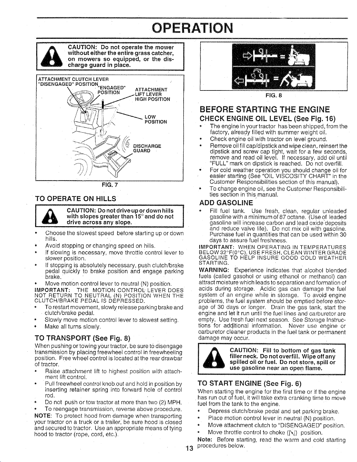
OPERATION
I without either the entire gr sas catcher,
on mowers so equipped, or the dis-
l charge guard in place.
ATTACHMENT CLUTCH LEVER
"DISENGAGED" POSITION
-"ENGAGED"
POSITION
FiG. 7
ATTACHMENT
HIGH POSITRON
POSiTiON
DISCHARGE
GUARD
/
TO OPERATE ON HILLS
_ CAUTION:_
gLJD_ross any slope. = :
• Choose the slowest speed before starting up or down
hills.
• Avoid stc ;)ping or changing speed on hills.
• If sIowing s necessary, move throttle control lever to
slower position.
• If stopping is absolutely necessary, push clutch/brake
pedal quickly to brake position and engage parking
brake.
, Move 'notion control lever to neutral (N) position.
IMPORTANT: THE MOTION CONTROL LEVER DOES
NOT RETURN TO NEUTRAL (N) POS_TtON WHEN THE
CLUTCH/BRAKE PEDAL IS DEPRESSED.
• To restart movement, stowty retease parking brake and
clutch/brake pedal.
• Slowly move motion control lever to slowest setting.
, Make all turns slowly.
with slopes greater than "15°and do not !
TO TRANSPORT (See Fig. 8)
When pushing or towing your tractor, be sure to disengage
transmission by placing freewheel control in freewheeling
position. Free wheel control is Iocated at the rear drawbar
of tractor.
• Raise attachment lift to highest position with attach-
ment lift control,
- Pullfreewheel control knob out and hold in position by
inserting retainer spring into forward hole of control
rod.
- Do not push or tow tractor at more than two (2) MPH.
- To reengage transmission, reverse above procedure.
NOTE: To protect hood from damage when transporting
your tractor or a truck or a trailer, be sure hood is closed
and secured to tractor. Use an appropriate means of tying
hood to tractor (rope. cord, etc.).
FIG, 8
BEFORE STARTING THE ENGINE
CHECK ENGINE OIL LEVEL (See Fig. 16)
, The engine in your tractor has been shipped, from the
factory, already filled with summer weight oit.
- Check engine oil with tractor on level ground.
• Remove oil fill cap/dipstick and wipe ctean, reinsert the
dipstick and screw cap tight, wait for a few seconds,
remove and read oil level. If necessary, add oil until
"FULL" mark on dipstick is reached. Do not overfill
• For cold weather operation you should change oi! for
easier starting (See "OIL VISCOSITY CHART" in the
Customer Responsibilities section of this manual).
= To change engine oil, see the Customer Responsibili-
ties section in this manual.
ADD GASOLINE
- Fill fuel tank. Use fresh, clean, regular unleaded
gasoline with a minimum of 87 octane. (Use of leaded
gasoline will increase carbon and lead oxidedeposits
and reduce valve life). Do not mix oiI with gasoline.
Purchase fuel in quantities that can be used within 30
days to assure fuel freshness.
IMPORTANT: WHEN OPERATING N TEMPERATURES
BELOW32°F(0°C), USE FRESH. CLEAN WINTER GRADE
GASOLINE TO HELP INSURE GOOD COLD WEATHER
STARTING.
WARNING: Experience indicates that alcohol blended
fuels (called gasohol or using ethanol or methanol) can
attract moisture which leads to separation and formation of
acids during storage. Acidic gas can damage the fuel
system of an engine while in storage. To avoid enaine
problems, the fuel system should be emptied before stor-
age of 30 days or Ionger. Drain the gas tank, start the
engine and let it run until the fuel lines and carburetor are
em3ty. Use fresh fuel next season. See Storage lnstruc_
tions for additional information. Never use engine or
carburetor cleaner products in the fuel tank or permanent
damage may occur.
o,tom ;fgo;, nk
! fill_erfill, Wipe off any
I spilled oil or fuel. Do not store, spill or
I use gasoline near an open flame.
TO START ENGINE (See Fig. 6)
When starting the engine for the first time or if the engine
has run out of fuel. it will take extra cranking time to move
fuel from the tank to the engine.
• Depress clutch/brake pedal and set parking brake.
, Place motion control ever in neutra (N) position.
Move attachment dutch to "DISENGAGED" position.
Move throttle control to choke (IX) position.
Note: Before starting, read the warm and cold starting
procedures below.
13

OPERATION
InsertKeyintoignitionandturn Keyclockwiseto"START" position and hold for five (5) seconds. Repeat this
oosition and t'eleaSe key as soon as engine starts, Do procedure three (3) times.
qo_run starter continuously for more than fifteen sec-
onus oer minute, If the engine does not start after
severn attempts, move throttle control to fast (,_}
oosltlon, wait a few minutes and try again, Ifengine still
does not start, move the throttle control back to the
choke (IXI) position and retry.
WARM WEATHER STARTING (50_ F and above)
o When engine starts, movethethrottle controltothe fast
(_) position,
The attachments and ground drive can now be JSed. If
me engine does not accept the load, restart the engine
ana allow it to warm up for one minute using the choke
as described above.
COLD WEATHER STARTING ( 500 F and below}
" When engine starts allow engine to run wlth the throttle
control n the choke (JXI)position until the engine "uns
roughly, then move throttle control to fast (,1_)position.
This may require an engine warm-up period from
severat seconds to several m_nutes. (]epending on the
temperature.
HYDROSTATIC TRANSMISSION WARM UP
o Before driving the uriit in cold weather, the transmis-
sion should be warmed up as follows:
Be sure the tractor is on level ground.
o Place the motion control lever in neutral.
Release the parking brake and let the clutch/brake
slowly return to operating position
Allow one minute for transmission to warm up.
This c_n be done dunng the engine warm uD
period,
The attachments can also be used during the engne
warm- Jp period after the transmfssio nhas been warmed
NOTE: f a_ a high altitude (above 3000 feet) or q cold
temoeratures (below 32 F) the carburetor fuel mixture may
peeo to be adjusted for best engine performance. See "TO
ADJUST CARBURETOR" in the Service and Adjustments
section of this manual.
PURGE TRANSMISSION
vet while the engine is run-
Never engage or disengage
To ensure proper operation and oerformance, it is recom-
menaed that the transmission be purged before operating
tractor for the Iirst time. This procedure wilI remove any
traoDea air inside the transmission whfdh may have devel-
Deec_during shipping of your tractor.
iMPORTANT: SHOULD YOUR TRANSMISSION REQUIRE
REMOVAL FOR SERVICE OR REPLACEMENT, IT
SHOULD BE PURGED AFTER REINSTALLATION
BEFORE OPERATING THE TRACTOR,
Piaee tractor safely on level surface with engine off and
parking brake set,
Disengage transmission by placing freewheel control
in freewheeling position (See "TO TRANSPORT" in
this section of manual).
Sittin ] inthe tractor seat, start engine, After the engine
is running move throttle control to.s_ow (,_) position.
With motion control tever in neutral (N) position, slowty
alsengago clutch/brake pedal
Move motion control lever to fun forward position and
qoid fretfly# (5', seconds. Move lever to full reverse
NOTE: During this procedure there wiii be no movement of
drive wheels. The air is being removed from hydraulic drive
system
o Move motion control lever to neutral (N) position. Sh ut-
off engine and set parking brake,
• Engage transmission by placing freewheel control in
driving position (See "TO TRANSPORT" in this section
of manual).
Sitting inthe tractor seat. start engine. Aftertheeng_ne
is running, move throttle control [o half (1/2) speed.
With motion control lever _nneutral (N) position, slowly
disengage clutch/brake pedal,
, Slowly move motion control lever forward, after the
tractor moves approximately five (5) feet. slowly move
motion control lever to reverse position After the
tractor moves approximately five (5) feet return the
motion control lever to the neutral (N) position. Repeat
this procedure with the mohon cent,tel lever three (3)
times,
• Your tractor is now Purged and now ready for normai
operatron.
MOWING TiPS
- Tire chains cannot be used when the -newer housing
is attached [o tractor,
- Mower should be properly _eveled for best mowing
performance. See "TO LEVEL MOWER HOUSING" in
the Service and Adjustments section of this manual,
, The left hand side of mowr_r should be usea for trim-
ming.
- Drive so that c',ppings are dlscr_arged onto the area
that has been cut Have the cut area to the right of the
machine. This will resuli ;n a more even distribution of
clippings and more uniform, cutting.
- When mowing large areas, start by turning to the right
so that clippings will discharge away from shrubs,
fences, driveways, etc. After one ortwo rounds, mow
In the opposite direction making left hand turns until
finished (See Fig. 9).
- If grass is extremely tal!, it should be mowed twice to
reduce loa(] and possible fire qazard from dried chp-
pings. Make first cut relatively high; the second to the
desired height.
• Do not mow grass when it is wet. Wet grass w_t}plug
mower and leave undesirable clumps, Allow grass to
dry before mowing.
• Always operate engine at fult throttle when mowing to
assure better mow_ng performance and proper dis-
charge of material. Regulate ground speed by select-
_ng a low enough gear 1o give the mower cutting
performance as well as the quality of cut desired.
When operating attachments, select a ground speed
that wilt suit the terrain and give best performance of
the attachment being used
f
r
14 FIG. 9

CUSTOMER ESPO LITIES
MAINTENANCE SCHEDULE ,
FILL IN DATES
AS YOU COMPLETE
REGULAR SERVICE
Check Brake Operation tf .....
Check Tire Pressure
T Chec k for Loose Fasteners t_
i_R Sharpen/Replace Mower Blades
_ LubricationOhart
T Check Battery Level/Recharge
: 0 Clean Battery and Terminals
R Check Transaxfe €ooling
Adjust Blade Belt(s) Tension
Adjust Motion Drive Belt(s) Tension
Check Engine Oil Level J
Change Engine Oil t##
Clean Air Kilter
N Clean Air Screen .
G Inspect Muffler/Spark Attester
' Pep,ace O,1Fi,ter (,fequ,pped)Cooling -1 1
N Clean Engine Fins 1##'2
Replace Spark Plug tf tt_
i/ !
I/7 t/
V', l
I/ t/
• V' V'
I/
_ _mtmmml iw_mllllm= _5 _ =lllxmml
v' "---'T'-'--'--
J,2_ v'
!/'2
I v'l i
!_1.2
SERVICE DATES
Replace Air F}lter Paper Cartridge !_2
'Repi'aceFuel Filter 1 I I_
I. Change moreoften whenoperatingundera heavytoador in high ambienttemperatures.
2 -Service more often whenoperatingin dirty ordusty conditions.
3- If equipped with eii filter, changeoit every50 hours.
4.- ReplaceMades more of'_enwhen mowing insandysoil
GENERAL RECOMMENDATIONS
The warranty on this tractor does not cover items that have
been subjected to operator abuse or negligence, To
receive full value [rom the warranty, operator must maintain
tractor as instructed in this manual.
Some adjustments will need to be made periodically to
properly maintain your tractor.
All adjustments in the Service and Adjustments section of
this manual should be checked at least once each season,
• Once a year you should replace the spark plug, clean
or replace air filter, and check blades and belts for
wear. A new spark plug and clean air filter assure
proper air-fuel mixture and he!p your engine run better
and last longer.
BEFORE EACH USE
• Check engine oil level:
• Check brake operation.
• Check tire pressure.
• Check for loose fasteners.
5 _If equipped with adjustable system,
6 - Not required if equipped With maintenance-free battery.
7 _Tighten front a×Ie pivot bert to 35 fLqbs, maximum.
Do not overtighten,
LUBRICATION CHART
(_ SPINDLE ZERK _. _._ SPINDLE ZERK (_)
(_ FRONT WHEEL"'I_ I'_........F'_"I"FRONT WHEEL (_)
BEARING ZERK _ _ _ BEARING ZERK
ENGINE (_)
©
CLUTCH
PIVOT(S)
(_SAE 30 OR 10W30 MOTOR OIL
(_ GENERAL PURPOSE GREASE
(_ REFER TO CUSTOMER RESPONSIBILITIES "ENGINE'_ SECTION
IMPORTANT; DO NOT OIL OR GREASE THE PIVOT POINTS
WHICH HAVE SPECIAL NYLON BEARINGS. VISCOUS LUBRI-
CANTS WILL ATTRACT DUST AND DIRT 'THAT WILL SHORTEN
THE LIFE OF THE SELF-LUBRICATING BEARINGS, IF YOU
FEEL THEY MUST BE LUBRICATED, USE ONLY A DRY, POW-
15 DERED GRAPHITE TYPE LUBRICANT SPARINGLY.
TRACTOR
CUSTOMER RESPC IBILITIES
Always deservesafetyruleswhen performingany mainte-
nance.
BRAKE OPERATION
If tractor requwes more than six (6) feet stopping distance
at h_ghspeed in highest gear, then brake must be adjusted.
fSee "TO ADJUST BRAKE" in the Service and Adjust-
men_s section of this manual).
TIRES
o Maintain proper air pressure in al_tires (See "PROD-
UCT SPECIFICATIONS" on page 3 of this manual).
o _.eee tires free of gasoline, o11,or insect controJ chemP
ca_swhich can harm rubber.
Avoid stumps, stones, deep ruts. sharp objec[s and
ether hazards that may cause tire damage,
BLADE CARE
For best results mower 3lades must be kept snarp. Re-
d,ace Dent or damaged blades.
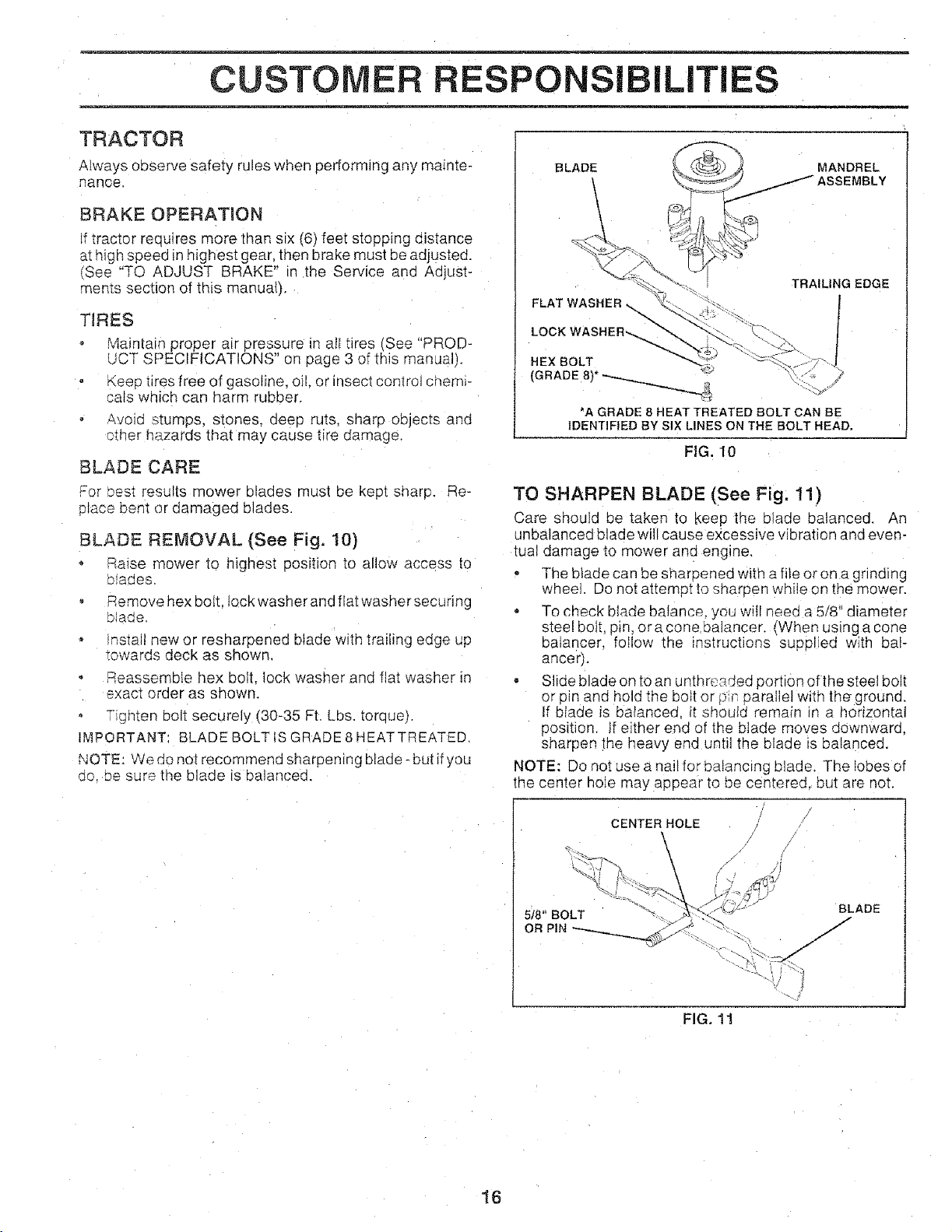
BLADE REMOVAL (See Fig, 10)
Raise mower to highest position 1oallow access to
oiaaes
Remove hex bolt fockwasheranc flat washersecunng
slaqe.
ms,all new or resharpened blade with trailing ec_geup
_owards deck as shown.
Reassemble hex bolt. lock washer and flat washer in
exact order as shown.
Tighten bolt securely (80-85 Ft. Lbs. torque).
I._,_PORTANT BLADE BOLT iS GRADE8HEATTREATED,
NOTE: We do not recommend sharpening blade - but ifyou
oo Desure the blade is balanced.
BLADE MANDREL
ASSEMBLY
TRAILING EDGE
FLAT WASHER_
HEX BOLT
(GRADE 8)*
*A GRADE 8 HEAT TREATED BOLT CAN BE
IDENTIFIED BY SIX LINES ON THE BOLT HEAD,
FIG. 10
TO SHARPEN BLADE (See Fig. 11)
Care should be taken to _<eepthe blade balanced. An
unbalanced blade will cause excessive vibration and even-
tual damage to mower and engine,
The blade can be sharoened with a file or on a grinding
wheel Do not attempt to sharpen while on the mower.
o To check blade balance, you will need a 5/8 diameter
steel bolt. pin, era cone ba]ancer. [When using acone
balancer, foIlow the instructions suppliec with bal-
ancer).
• Slide blade on to an unthreaded portion of the steel bolt
or pin and hold the bolt or [_'r,oarallel w_tnthe ground.
tf blade _s balanced, it shoulc remair ir a horizontal
position, if either end of the blade moves downward,
sharpen the heavy end until the blade is balanced.
NOTE: Do not use a nail for balancing blade. The lobes of
the center hoJe may appear to be centered, but are not.
16
518" BOLT
OR PiN
CENTER HOLE
BLADE
FIG. 11

CUSTO RESPONSIBILITIES
BATTERY
Your tractor has a battery charging system which is suffi-
cient for normal use. However periodic charging of the
battery with an automotive charger will extend its life.
o Keep battery and terminals clean.
- Keep battery bolts tight,
• Keep small vent holes open.
• Recharge at 6-10 amperes for 1 hour.
TO CLEAN BATTERY AND TERMINALS
Corrosion and dirt on the battery and terminals can cause
the battery to "leak" power.
• Open battery box door.
• Disconnect BLACK battery cabte first then RED bat-
tery cable anc remove battery from tractor.
, Rinse the battery with plain water and dry.
Clean terminals and battery cable ends with wire brush
until bright,
. Coat terminals with grease or petroleum jetly.
• Reinstall battery (See "CONNECT BATTERY" in the
Assembly section of this manual).
V-BELTS
Check V-belts for deterioration and wear after I00 hours of
operation and replace if necessary. The belts are not
adjustable. Re place oelts if they begin to slip from wear,
TRANSAXLE COOLING
The fan and cooling fins of transmission should be kept
clean to assure 3roper cooling.
Do not attempt to clean fan or transmission while engine is
running or while the transmission is hot.
- Inspect cooling fan to be sure fan blades are intact and
clean.
Inspect cooling fins for dirt. grass clippings and other
materials; To prevent damage to seals, do not use
compressed air or high pressure sprayer to clean
cooling fins.
SAE VISCOSITY GRADES
30 ° 32o 40" 60 ° 80 t00
-30" -20° -100 0_ t0' 20 30_ 40°
TEMPERATURE RANGE ANT{CIPATED BEFORE NEXT OIL SHANGE
FIG. 12
NOTE: Although multi-viscosity oils (5W30, 10W30 etc.)
improve starting in cold weather, these multi-viscosity oils
will result in increased oil consumption when used above
32°F. Check your engine oil level more frequently to avoid
possible engine damage from running tow on oil.
Change the oil after the first two hours of operation and
every 25 hours thereafter or at least once a year if the
tractor is not used for 25 hours ir one year.
Check the crankcase oil level before starting the engine
and after each eight (8) hours of operation. Tighten oil fill
cap/dipstick securely each time you check the oi level.
TO CHANGE ENGINE OIL (See "ig, t3)
Determine temperature range expected before oil change.
All oil must meet API service classification SF or SG.
- Be sure tractor is on level surface.
o Oil will drain more freely when warm.
• Catch oit in a suitabfecontainer.
Remove oil fiit cap/dipstick Be careful not to allow dirt
to enter the eng ne when changing oit.
Remove drain plug.
After oil has drained completely, replace oil drain ptug
and tighten securely.
Refiti engine with oil through oil filt dipstick tube. Pour
slowly. Do not overfill. For approximate capacity see
"PRODUCT SPECIFICATIONS" on page 3 of this
manual
- Use gauge on oil filf cap/dipstick for checking levet. Be
sure dipstick cap is hghtened securely for accurate
reading. Keep oil at "FULL" line on dipstick.
TRANSAXLE PUMP FLUID
The transaxle was sealed at the factory and fluid mainte-
nance is not required for the life of the transaxle. Should the
transaxle ever leak or require servicing, contact your near-
est authorized service center/department.
ENGINE
LUBR!CATJON (See Fig. 12)
Only use high quality detergent oil rated witP APt service
classification SF or SG. Select the oil's SAE wscostty grade
according to your expected operating temperature.
FILL
CAPtDtPSTICK
J
OiL DRAIN
PLUG
FIG. ! 3
17
 Loading...