

Craftsman 917256660 Owner’s Manual

/:IN°
DEL NUMBER 917.256660
oAssembly
oOperation
oCustomer Responsibilities
- Service and Adjustments
- Repair Parts
OWNER'S MANUAL
CAUTION: Read and follow all safety rules and instructions before operating this equipment.
FOR CONSUMER ASSISTANCE HOT LINE, CALL THIS TOLL FREE NUMBER: 1-800-659-5917
1/111111111111111II

Safe Operation Practices for Ride-On Mowers
SAFETY RULES
IMPORTANT: THIS CUTTING MACHINE IS CAPABLE OF AMPUTATING HANDS AND FEET AND THROWING OBJECTS..
FAILURE TO OBSERVE THE FOLLOWING SAFETY INSTRUCTIONS COULD RESULT IN SERIOUS INJURY OR DEATH_
L
GENERAL OPERATION
o
Read, understand, and follow all |nsl_Jctions [n the manual
and on the machine before starting,
Only allow responsible adults, who are familiar with the_
instructions, to operate the machine,
o
Clear the area of objects such as rocks, toys, wire. etc.
whichcould be picked up and thrown by the blade°
Be sure the area isclear of other people before mowing. Stop
machine if anyone enters the area.
o
Never carry passengers..
e
Do notmow in reverse unless absolutely necessary. Always
Jook down and behind before and while backing.
o
Be aware of the mower discharge direction and do not point
it at anyone. Do not operate the mower without either the
entire grass catcher or the guard in place.
Slow down before turning
Never reave a running machine unattended. Always turn off
blades, set parking brake, stop engine, and remove keys
before dismounting_
Turn off blades when not mowing.
Stop engine before removing grass catcher or unclogging
chute
Mow only in daylight or good artificial lighL
Do not operate the machine while under the influence of
alcohol or drugs.
Watch for traffic when operating near or'crossing roadways..
Use extra care when loading or unloading the machine into
a trailer or truck._
II. SLOPE OPERATION
Slopes are a major factor related to loss-of-control and
tipover accidents, which can result in severe injury or death.
All slopes require extra caution. If you cannot back up the
slope or if you feel uneasy on it, do not mow it.
DO"
• Mow up and down slopes, not across..
• Remove obstacles such as rocks, tree limbs, etc..
- Watch for holes, ruts, or bumps. Uneven terrain could
overturn the machine.. Tall grass can hide obstacles.
o Useslow speed Choose a low gear so that you wil! not have
to stop or shift while on the slope,
• Follow the manufacturer's recommendations for wheel
weights or counterweights to improve stability.
• Use extra care with grass catchers or other' attachments.
These can change the stability of the machine.
III. CHILDREN
Tragic accidents can occur'if the operator is not alert to the
presence of children. Children are often attracted to the
machine and the mowing activity., Never assume that
children will remain where you last saw them.
• Keep children out of the mowing area and under the watchful
care of another responsible adult.
° Be alert and turn machine off if children enter the area,
• Before and when backing, look behind and down for small
chirdren
• Never carry children_ They may fall off and be seriously
injured or interfere with sale machine operation.
• Never allow children to operate the machine.
° Use extra care when approaching blind comers, shrubs,
trees, or other objects that may obscure vision.
IV. SERVICE
• Use extra care in handling gasoline and other fuels They are
flammable and vapors are explosive.
Use only an approved container_
Never remove gas cap or add fuel with the engine
running_ Allow engine to cool before refueling, Do not
smoke
Never refuel the machine indoors°
Never store the machine or fuel container inside where
there is an open flame, such as a water heater
• Never run a machine inside a closed area.
= Keep nuts and bolts, especially blade attacht_, nt bolts, tight
and keep equipment in good condition.
• Never tamper wilh safety devices., Check their proper
operation regularly.
• Keep'machine free of grass, leaves, or other debris build-up_
Clean oil or fuel spillage. Allow machine to cooF before
storing.
. Stop and inspect the equipment if you strike an object.
Repair, if necessary, before restarting
• Never make adjustments or repairs with the engine running
- Grass catcher components aresubject to wear, damage, and
detedoration, which could expose moving parts or allow
objects to be thrown. Frequently check components and
replace with manufacturer's recommended parts, when nec-
essary.
= Mower blades are sharp and can cut Wrap the blade(s) or
wear groves, and use extra caution when servicing them.
• Check brake operation frequently., Adjust and service as
required.
= Keep all movement on the slopes sfow and gradual Do not
make sudden changes in speed or direction,
• Avoid starting or stopping on a slope, if tires lose traction,
disengage the blades and proceed slowly straight down the
slope,
Look for this symbol to point out im-
portant safety precautions. It means
CAUTION!!I BECOMEALERT!!! YOUR
SAFETY IS INVOLVED.
DO NOT:
" Do not turnon slopes unless necessary, and then, turnslowly
CAUTION: Always disconnect spark plug
and gradually downhill, ifpossible.
• Do not mow near drop-oils, ditches or embankments.. The
mower could suddenly turn over if a wheel is over the edge
ofa cliff or ditch, or ifan edge caves in.
• Do not mow on wet grass. Reduced {_:actioncouldcause
Uli,lU ....... ,llll kl ................
spark plug in order to prevent accidental
wireandplacewirewhereitcannotcontact
starttng when setting up, transporting,
adjusting or making repairs,
sliding
• Donot try tostabilize the machineby puttingyourfoot onthe
ground.
• Do not use grass catcher onsteep slopes.
The engine exhaust from this product con.
tains chemicals known to the State of Califor
WARNING &
nia to cause cancer, birth defects, or other
reproductive harm.
2
J,l,: :.................

CONGRATULATIONS on your purchase of a Sears
Tractor,, It has been designed, engineered and manufac-
tured to give you the best possible dependability and
performance.
Should you experience any problem you cannot easily
remedy, please contact your nearest Sears Authorized
Service CentedDepartmento We have competent, well-
trained technicians andthe proper tools to service or repair
this tractor.
Please read and retain this manual° The instructions wilt
enable you to assemble and maintain your tractor properly.
Always observe the "SAFETY RULES".
MODEL
NUMBER 917.256660
SERIAL
NUMBER
DATE OF PURCHASE
TH EMODEL AN DSERIAL NUMBERS WILL BEFOUND
ON A PLATE UNDER THE SEAT.
YOU SHOULD RECORD BOTH SERIAL NUMBER AND
DATE OF PURCHASE AND KEEP IN A SAFE PLACE
FOR FUTURE REFERENCE.
MAINTENANCE AGREEMENT
A Sears Maintenance Agreement is available on this prod-
ucto Contact your nearest Sears store for details.
CUSTOMER RESPONSIBILITIES
o Read and observe the safety rules°
, Follow a regular schedule in maintaining, caring for and
using yourtractor.
, Follow the instructions under "Customer Responsibili-
ties" and "Storage" sections of this owner's manual.
WARNING: This tractor is equipped with an internal
combustion engine and should not be used on or near any
unimproved forest-covered, brush-covered or grass-cov-
ered land unless the engine's exhaust system is equipped
with a spark arrester meeting applicable local or state laws
PRODUCT SPECIFICATIONS
HORSEPOWER: 19..0
GASOLINE CAPACITY 3°5 GALLONS
AND TYPE: UNLEADED REGULAR
OIL TYPE (API-SF!SG): SAE 30 (above 32°F)
SAE 5W-30 (below 32°F)
OIL CAPACITY: 30 PINTS
SPARK PLUG: CHAMPfON RJ19LM
(GAP: .030") STD361458
VALVE CLEARANCE: INTAKE: .004" - _006"
EXHAUST: _007"- .009"
GROUND SPEED (MPH): FORWARD:
1st 11
2nd 1.5
3rd 23
4th 35
5th 4.4
6th 57
REVERSE: 17
TIRE PRESSURE: FRONT: 14 PSI
REAR: 10 PSI
CHARGING SYSTEM: 5 AMPS BATTERY
5 AMPS HEADLIGHTS
BATTERY: AMP/HR: 30
MiN CCA: 240
CASE SIZE: U1R
BLADE BOLT TORQUE: 30-35 FT. LBS.
(ifany). If a spark arrester is used, it should be maintained
in effective working order by the operator,
in the state of California the above is required by law
(Section 4442 of the California Public Resources Cede)
Other states may have similar laws, Federal lawsapply on
federal lands. A spark arrestor for the muffler is available
through your nearest Sears Authorized Service Center/
Department (See REPAIR PARTS section ofthis manual)°
LIMITED TWO YEAR WARRANTY ON CRAFTSMAN RIDING EQUIPMENT
For two (2) years from the date of purchase, if this Craftsman Riding Equipment is maintained, lubricated and tuned up according
to the instructionsin the owner's manual, Sears will repair or replace, free of charge, any parts lound to be defective in material or
workmanship.
This Warranty does not cover:
• Expendable items which become worn during normal use, such as blades, spark plugs, air cleaners, belts, etc
• Tire replacement or repair caused by punctures from outside objecls, such as nails, thorns, stumps, or glass,
• Repairs necessary because of operator abuse, negligence, improperstorage or accident or the failure to maintain the
equipment according tothe instructions contained in the owner's manual.
• Riding equipment used for commercial or rental purposes.
LIMITED 90 DAY WARRANTY ON BATTERY
For ninety (90) days from date of purchase, if any battery included with this riding equipment proves defective in material or
workmanship and our testing determines the battery will not hold a charge, Sears will replace the battery at no charge.
IN-HOME WARRANTY SERVICE ON YOUR CRAFTSMAN RIDING EQUIPMENT IS AVAILABLE AT NO-CHARGE FOR 30
DAYS FROM THE DATE OF PURCHASE. PLEASE CONTACT YOUR NEAREST SERVICE CENTER AFTER 30 DAYS FROM
THE DATE OF PURCHASE, WARRANTY SERVICE IS AVAILABLE BY TAKING YOUR CRAFTSMAN RIDING EQUIPMENT TO
YOUR NEAREST SEARS SERVICE CENTER. (1N-HOMEWARRANTY ,_'ERVICE WILL STILL BE AVAILABLE AFTER 30 DAYS
FROM THE DATE OF PURCHASE BUT A STANDARD TRIP CHARGE WILL APPLY..) TFIIS_WARRANTY APPLIES ONLY
WHILE THIS PRODUCT IS IN THE UNITED STATES.
This Warranty gives you specific legal rights,and you may also have other rights which may vary from state to state.
SEARS, ROEBUCK AND CO., D/817 WA, HOFFMAN ESTATES, IL 60179
3

TABLE OF CONTENTS
SAFETY RULES ....................... ;.................................... 2
PRODUCT SPECIFICATIONS ...................................... 3
CUSTOMER RESPONSIBILITIES ..................... 3, 17-19
WARRANTY .................................................................. 3
TRACTOR ACCESSORIES .......................................... 5
ASSEMBLY ................................................................ 7-9
OPERATION ........................................................... 11-15
iNDEX
A
Accessories .............................................................5
Adjustments:
Brake ...................................................22
Carburetor .................................................25
Mower
Front-To-Back..............................2I
Side-To-Side ................................20
Throttle Control Cable ......................24
Air Fitter, Engine..................................................t 8
Air Screen, Engine ......................................18
Assembly ...........................................................7-10
B
Batlery:
Charging ........................................................8
Cleaning .................................................17
Starting with Weak Battery.............24
Storage ........................................................26
Terminals ...........................................17
Belt:
Motion Drive
Removal/Replacement ..................23
Mower Blade(s)
Removal/Replacement ................22
Blade:
Sharpening .................................................17
Replacement ......................................17
Brake Adjustment .......................................22
C
Carburetor Adjustment ..............................25
Controls, Tractor ...........................................12
Customer Responsibilities ....................16-19
Engine:
Air Filter...................................................18
Air Screen, Engine ..........................18
Cooling Fins, Engine ............................19
Engine Oil ................................... t8
Fuel Filter ........................................19
Spark Plug(s) ..................................19
Tractor:
Battery .........................................................17
Blade .............................................17
Lubrication Chart ..........................!6
Maintenance Schedule ................16
Tire Care ................................8,17,23
Transaxle .....................................................18
Cutting Height, Mower .....................................13
E
Electrical:
Interlocks and Relays ........................24
Schematic .................................................29
Wiring Diagram .......................................30
Engine:
Air Filter ....................................................18
Air Screen .................................................18
Cooling Fins, Engine ........................19
Oil Change ....................................................18
Oil Level ............................................14,t8
Oil Type ................................................18
Preparation ..................................................14
Repair Pads .................................30-47
Stading .........................................................14-t5
Storage ..................................................26
Filter;
Air Filter .........................................................18
Fuel ....................................................19
Fuel;
Type ...........................................................14
Storage ..............................................26
Fuse .....................................................................24
Hood Removalllnstallation ......................24
LevelingMower Deck ..................................20
Lubrication:
Chad .....................................................16
Maintenance Schedule ............................16
Mower:
Adjustment, Front4o-Back .................21
Adjustment, Side-to-Side ..................20
Blade Sharpening ........................................17
Blade Replacement ........................... 17
Cutting Height ............................................13
Installation ......................................................20
Operation ..................................................14
Removal ....................................................20
Mowing Tips ...........................................................15
Muffler ..........................................................19
Spark Attester ..................................3,40
,. O
011:
Cold Weather Conditions .:........14,18
Engine ............................................14,18
Storage ..................................................26
Operation .............................................................11-15
Operating Mower .........................................14
MAINTENANCE SCHEDULE ...................................... 16
SERVICE AND ADJUSTMENTS ............................ 20-25
STORAGE ................................................................... 26
TROUBLESHOOTING ............................................ 27-28
REPAIR PARTS - TRACTOR ................................. 30-47
REPAIR PARTS - ENGINE .................................... 48-53
PARTS ORDERING/SERVICE ................ BACK COVER
Options:
Accessories ............................................5
Spark Arrestor ...................................3,40
P
Parking Brake ............................................13
Pads Bag .................................................................6
Pads, Replacement]Repair ...................30-47
Product Specifications......................................3
R
Repair Pads ..........................................30_47
F
S
Safety Rules ..................................................2
Seat ..............................................................................8
Service and Adjustments ................20-25
Carburetor ......................................................25
Fuse ......................................................24
Hood Removaltlnstallation ..............24
Motion Drive Belt
H
L
M
Throttle Control Cable Adjustment ..........24
Tires ..................................................................8,17,23
Transaxle .......................................................18
Warranty ............................................................3
Wiring Diagram ..............................................30
WMng Schematic .................................................29
RemovallReplacement ................23
Mower Belt(s)
RemovallReplacement .................21
Mower Adjustment
Front-to-Back ....................................21
Side-to-Side ...................................20
Mower Removal .......................................20
Tire Care ..................................8,17,23
Slope Guide Sheet .....................................55
Spark Plug(s) .............................................18
Specifications .......................................................3
Starting the Engine ................................14-15
Steering Wheel ........................................7,23
Stopping the Tractor .................................t3
Storage ..............................................................26
T
Trouble Shooting Chart .....................27-28
W
4

ACCESSORIES AND ATTACH
These accessories and attachments were available through most Sears retail outlets andservice centers when the tractorwas purchased°
Most Sears stores can orderthese items for you when you provide the model number ofyour tractor_
ENGINE
SPARKPLUG
GASCAN
ENGINEOIL
FUELSTABILIZER AIR FALTER
MAINTENANCE
ENTS
illllll,,, ...............
BLADES BELTS
%
_J
PERFORMANCE
Sears offers a widevariety ofattachmentsthat fit yourtractor. Many ofthese are listed below with briefexplanations of how theycan help
you..This list was current at the time ofpublication; however, it may change infuture years - more attachments may be added, changes
may be made in these attachments, orsome may no longer be available or fit your model Conta_ctyour nearest Sears store for the
accessories and attachments that are available for your tractor.
Most of these attachments do not require additional hitches or conversion kits(those that do are indicated) and are designed for easy
attaching and detaching°
AERATOR promotes deep root growth for a healthy lawn. Ta-
pered 2o5-inch steel spikes mounted on 10-inch diameter discs
puncture holes in soil at close intervats to let moisture soak inn
Steel weight tray for increased penetration.
BAGGER lets you collect grass clippings and leaves for a
healthier, nearer looking lawn. Two Permanex containers hold
30-gallon plastic bags..
BUMPER protects front end of tractor from damage°
CARTS make hauling easy, Variety of sizes available, plus
accessories such as side panel kits, tool caddy, cart cover,
protective mat and doily.
CORING AERATOR takes small plugs out of soil to allow mois-
ture and nutrients to reach grass roots, 36-inch swath_ 24
hardened steel coring tips. t50 lb. capacity weight tray..
EASY OIL DRAIN VALVE makes oil changes easier, faster_
FRONT NOSE ROLLER canters in front ofmower deck to reduce
chances of "scalping" on uneven terrain°
GANG HITCH lets you tow 2 or 3pu!l-behind attachments at once,
such as sweepers, dethatchers, aerators (not for use with roIlers,
carts or other heavy attachments).
GAUGE WHEELS on both sides of the mower deck reduce
chances of"scalping" on uneven terrain. For mower decks not so
equipped°
MULCH RAKEjDETHATGHER loosens soil and flips thatchand
matted leaves to lawn surface for easy pickup.. Twentyspdng fine
teeth.. Useful to prepare bare areas forseeding. Available for front
or rear mounting. HIGH PERFORMANCE REEL-ACTION
SPRING TINE DETHATCHER covers 36-inch wide path and
tosses thatch into large hopper. Mounts behind tractor°
MULCHING CLOSE-OUT PLATE KIT, once instaIled, lets you
mulch, d_scharge or bag clippings (bagger optional) without
changing blades° For models not equipped as 3oin-1Convertible
mowers. See "MOWER in the Repair Parts section of this
manual.
RAMP TOPS AND FEET tat you load and unload tractor from a
pickup truck. Use with 2x 8 or 2 x !0 lumber,,
ROLLER for smoother lawn surface. 36-inch wide, 18-inch
diameterwater-tight drum holds upto390 Ibs,.ofweighL Rounded
edges prevent harm to turf. Adjustable scraper'automatically
cleans drum°
SNOW BLADE forsnow removaEonly. 14-inch high, 48-inch wide
bladeclears42-inchpathwhenangledlettor righL Raises, lowers
with side lever. Adjustable skids; replaceable, reversible scraper
bar° (Use with tire chains and wheel weights and/or rear drawbar
weight.)
SNOWTHROWER has 40-inch swath. Drum-type auger handles
powdery and wet/heavy snow° Mounts easily with simple pin
arrangement.. Discharge chute adjusts from tractor seat.. 6-inch
diameter spout discharges snow 10 to 50 feet. Lift controlled at
tractor seat. (Use with chains and wheel weights and/or rear
drawbar weight.)
SPRAYERS use 12-volt DC electric motor that connects to the
tractor battery or other 12-volt source., includes booms for
automatic spraying and hand he_dwand for spot spraying. Wand
has adjustable spray pattern° For applying herbicides, insecti-
cides, fungicides and liquid fertilizers_.
SPREADER/SEEDERS make seeding, fertifizing, andweed kiII.
ing easy_ Broadcast spreaders are also usefLd for granular de-
Icers and sand. '
SWEEPERS let you collect grass clippings and leaves.
TILLER has 5hp engineand 36-inch swath to prepare seed beds,
cultivate and compost garden residue, Tiller has its own built-in
lift and depth control system and does NOT require a sleeve hitch.
Fits anylawn, yard orgarden tractor, Simply hook up tothe tractor
drawbar and go1 Optional accessories convert unit for
dethatching, aerating, hiLltng_.without tools.
TIRE CHAINS are heavy duty; closely spaced extra-large cross
links give smooth ride, outstanding traction..
TRACTOR CAB has heavy duty vinyl fabric over tubular stee_
frame, ABS plastEctop; clear plastic windshield offers 360degree
visibility_ Hinged metal doors with catch. Keeps operator warm
and dry. Remove vinyl sides and windshields for use as sun
protector in summer_ Optional accessories Include: tinted/
tempered solid safety glass windshield with hand operated wiper;
12-volt amber caution lightfor mounting on cab top.
VACS for powerful collection ofheavy grass clippings and leaves.
Optional wand attachment to pick up debris in hard-to-reach
places_ VAC/CHIPPER _ncludes a chipper-shredder,
WEIGHT BRACKET for drawbar for snow removal applications.
Uses (1) 55 lb.weight.,
WHEEL WEIGHTS for rear wheels provide needed traction for
snow removal or dozing heavy materials.
5

_ILLL I I Ill l Ill
CONTENTS OF
iiH,,i
Parts Bag contents shown full size
HARDWARE PACK
ii iJl
Parts packed separately in carton
(1) Hex Bolt
3/8-16 x I
(1) Large Flat Washer
(1) Hex Bolt 5116-18 x 1-114
(1) Shoulder Bolt
5/I 6-18
(1) Lockwasher 3/8
(t) Locknut 5116-18
(1) Hex Bolt 1/2-13 x I
Plate
Video
Cassette
Seat
Steering
Wheel
_ Mulcher
Steering
Boot
Parts Bag
Manual
Parts bag contents not shown full size
Wheels
(2) Shoulder (2) Washers 3/8
Bolts x 7/8 x 14 Gauge
_z / (2) Gauge
(2) Hex Bolts /'_"_
1/4-20 x 3/4
(2) Washers
9/32 x 5/8 x 16 (2) Lock Washers 1/4
..................... ,, ,, ,,,,,
Steering _ _ Steering Wheel
Extension Insert
Shaft
2) Center-
lock Nuts
Steering Wheel
Adapter
_.L_ZZ3
(2) Latch Hook
Assembfys
(2) Keys
Slope Sheet
6

ASSEMBLY
i iii,l,,i,,,ll ii
Your new tractor has been assembled at the factory with exception ofthose parts _eftunassembled for shipping purposes_
To ensure safe and proper operation ofyour tractor, allparts and hardware you assemble must be tightened securely. Use
the correct tools as necessary to insure proper tightness.
TOOLS REQUIRED FOR ASSEMBLY
A socket wrench set will make assembly easier_ Standard
wrench sizes are listed°
(1) 5/16"wrench (1) 9/16"wrench
(2) 7/16" wrenches (1) Phillips screwdriver
(2) 1/2" wrenches Utility knife
(1) 3/4" wrench Tire pressure gauge
(1) 3/4" socket with drive ratchet
When right and left hand is mentioned in this manual, it
means when you are in the operating position (seated
behind the steering wheel).
TO REMOVE TRACTOR FROM CARTON
UNPACK CARTON
. Remove all accessible loose parts and parts cartons
from carton (See page 6).
° Cut, from top to bottom, along lines on allfour corners
of carton, and lay panels fiat,.
• Remove mower and packing materials,.
= Check for any additional loose parts or cartons and
remove°
STEERING
BEFORE ROLLING TRACTOR OFF SKID
ATTACH STEERING WHEEL (See Fig. 1)
ASSEMBLE EXTENSION SHAFT AND BOOT
o Slide extension shaft onto lower steering shaft. Align
mounting holes in extention and lower shafts andinstall
5/16 hex bott and locknuL Tighten securely.
IMPORTANT: TIGHTEN BOLT AND NUT SECURELY TO
18-22 FT. LBS TORQUE_
= Place tabs of steering boot over tab slots in dash and
push down to securer
INSTALL STEERING WHEEL
• Position front wheels ofthe tractor so they are pointing
straight forward.
o Slide steering wheel adapter onto steering shaft exten-
sion.
° Position steering wheel and sleeve assembty so cross
bars are horizontal (left to right) and slide onto adapter,,
° Assemble large flat washer, 3/8 lock washer, 3/8 hex
bolt and tighten securely.
° Snap steering wheel insert into center of steering
wheel.
• Remove protective plastic from tractor hood and,grill.
IMPORTANT; CHECK FOR AND REMOVE ANY STAPLE;S
IN SKIDTHAT MAY PUNCTURETIRES WHERE TRACTOR,
IS TO ROLL OFF SKID..
SHAFT
FIG. 1
TO ROLL TRACTOR OFF SKID (See Opera-
tion section for location and function of con-
trols)
• Press lift leverplungerand raise attachment liftlever to
itshighest position._
° Release parking brake by depressing clutch/brake
pedal.
o Place gearshift lever in neutral (N) position.
° Roll tractor backwards off skid_
7
ILII
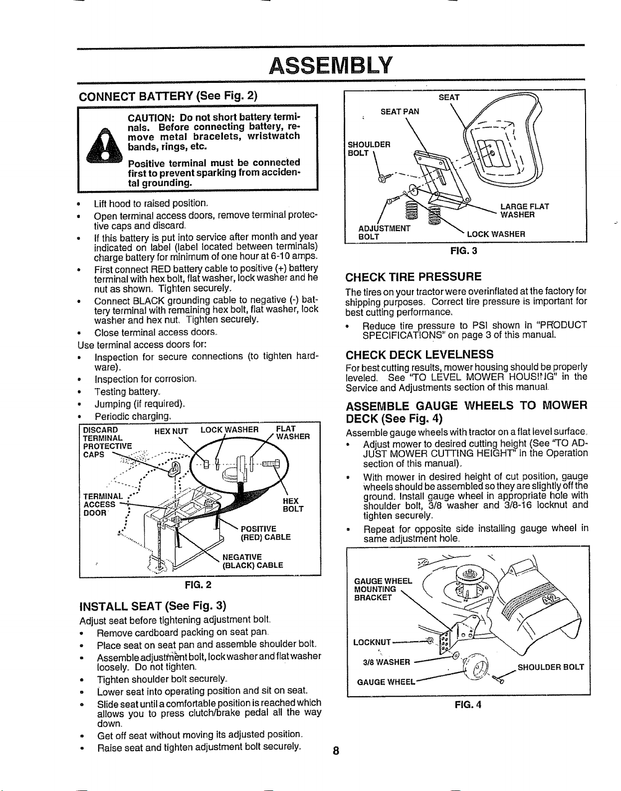
CONNECTBATTERY(SeeFig. 2)
........... , i,, i, =u=
CAUTION: Do not short battery termi-
nals. Before connecting battery, re-
move metal bracelets, wristwatch
bands, rings, etc.
Positive terminal must be connected
first to prevent sparking from acciden-
tal grounding. .....................
= Lifthood to raised position.
° Open terminal access doors, remove terminal protec-
tive caps and discard.
° if this battery is put intoservice after month and year
indicated on label (label located between terminals)
charge battery for minimum of one hour at 6-10 amps.
= First connect RED battery cable to positive(+) battery
terminal with hex bolt, flat washer, lock washer and he
nut as shown° Tighten securely.
• Connect BLACK grounding cable to negative (-) bat-
tory terminal with remaining hex bolt, flat washer, lock
washer and hex nut, Tighten securely_
Close terminal access doors,,°
Use terminalaccess doors for:
= inspection for secure connections (to tighten hard-
ware)_
o
Inspection for corrosion_
o
Testing battery.
o
Jumping (if required)_
°
Periodic charging.
DISCARD HEX NUT
TERMINAL
PROTECTIVE "_\
CAPS
TERMINAL .'"
ACCESS
DOOR .
#
LOCK WASHER FLAT
)OSITIVE
(RED) CABLE
WASHER
HEX
BOLT
SEAT PAN SEAT
SHOULDER ',_,,\\.._ \ \ \ \\ \
BOLT T
sTMENT\ LOCKWAS.ER
FIG. 3
CHECK TIRE PRESSURE
The tires onyourtractorwere overinflated atthe factory for
shipping purposes_ Correct tire pressure is importantfor
best cutting performance.
° Reduce tire pressure to PS1 shown in "PRODUCT
SPECIFICATIONS" on page 3 of this manual
CHECK DECK LEVELNESS
For best cutting results, mower' housing should be properly
leveledo See "TO LEVEL MOWER HOUS!HG" in the
Service and Adjustments section ofthis manual
ASSEMBLE GAUGE WHEELS TO MOWER
DECK (See Fig. 4)
Assemble gauge wheelswithtractorona fiat level surface
° Adjust mower to desired cutting height (See "TO AD-
JUST MOWER CUTTING HEIGHT' in the Operation
section of this manual).
° With mower in desired height of cut position, gauge
wheels should be assembled sothey are slightly offthe
ground. Install gauge wheel in appropriate hole with
shoulder boEt,3/8 washer and 3/8-t6 locknut and
tighten securely.
• Repeat for opposite side instatling gauge wheel in
same adjustment hole_
NEGATIVE
(BLACK) CABLE
FIG. 2
INSTALL SEAT (See Fig. 3)
Adjust seat before tighteningadjustment boll
• Remove cardboard packing on seat pan
, Place seat on seat pan and assemble shoulder bolt.
° Assemble adjusthi_'nt bolt,lock washerandflatwasher
loosely° Do nottighten
= Tighten shoulder bolt securely°
o Lower seat into operating positionand sit on seat.
° Slide seat untila comfortablepositionis reached which
allows you to press clutch/brake pedal all the way
down.
° Get off seat without moving itsadjusted position.
. Raise seat and tighten adjustment bolt securely.
GAUGE WHEEL
MOUNTING
BRACKET
LOCKNUT_
BOLT
FIG. 4
8

INSTALL MOWER AND DRIVE BELT (See
Figs. 5 and 7)
Be sure tractoris on level surface and mower suspension
arms are raised with attachment liftcontrol. Engage park-
ing brake,,
. Cut and remove ties securing anti-sway bar and belts.
Swing anti-sway bar to left side of mower deck,,
. Slide mower undertractorwith discharge guard toright
side of tractor.
IMPORTANT' CHECK BELT FOR PROPER ROUTING IN
ALL MOWER PULLEY GROOVES, INSTALL BELT iNTO
ELECTRIC CLUTCH PULLEY GROOVEr
• Install one front link in top hole of the R.H, front mower
bracket and RoH_front suspension bracket. Retain with
two single loop retainer springs as shown°
• Install secondfront linkin Loll front suspension bracket
only and retain with single loop retainer spring as
shown.
• Turn height adjustment knob counterclockwise until it
stops.,
• Lower mower linkage with attachment lift control.
o Place the LoHosuspension arm on outward pointing
deck pin., If necessary, rock and raise front of mower
to align deck pin with the hole in suspension arm.
Retain with double loop retainer spring with loopsdown
as shown,,
= Slide left side of mower back and installthe unattached
front link in top hole of the L°H_front mower bracket.
Retain with single loop retainer spring as shown..
DOUBLE LOOP
RETAINER SPRING
CHASSIS (outward pointing
BRACKET deck pins)
BLY
o
o
o
o
o
CHECK MOWER LEVELNESS
Forbest cutting results, mower should bepropedy leveled,
See "TO LEVEL MOWER HOUSING" inthe Service and
Adjustments section of this manual.
CHECK FOR PROPER POSITION OF ALL
BELTS
See the figures that are shown for replacing motion, mower
drive, and mower blade drive belts in the Service and
Adjustments section of this manual, Verify that the belts
are routed correctly_
SUSPENSION
ARMS
Place the R.H_suspension arm on outward pointing
deck pin. If necessary, rock and raise front of mower
to align deck pin with the hole in suspension arm,
Retain with double loop retainer spring with loops down
as shown,,
Connect anti-sway bar to chassis bracket under left
footrest and retain with double !oop retainer spring_
Turn height adjustment knob clockwise to remove
slack from mower suspension,
Raise mower to highest position,,
Assemble gauge wheels (See "TO ADJUST GAUGE
WHEELS" in the Operation section of this manual),,
FRONT
SUSPENSION
ELECTRIC
CLUTCH
PULLEY,
FRONT
MOWER
BRACKET
BRACKETS
SHOULDER
BOLT
GAUGE
WHEEL
318WASHER
USE PLtERSFOR
RETAINER SPRINGS
FRONT
LINK
SINGLE
LOOP
RETAINER
SPRINGS
3_16
CENTER
LOCKNUT
/
DOUBLE LOOP
RETAINER ANTI-SWAY
SPRING BAR
IDLER /
PULLEY
DISCHARGE GUARD
FIG. 5
9

_,L i i illl ii i illll
INSTALL MULCHER PLATE (See Figs. 6A and
6B)
• Install two latch hooks to mulcher plate using screw,
washer, lock washer, and weld nut as shown°
NOTE: Pre-assemble weld nut to latch hook by inserting
weld nut from the top with hook pointing down.
° Tighten hardware securely.
• Raise and hold deflector shield in upright position°
= Place front of mulcher plate over front of mower deck
opening and slide into place, as shown.
o Hook front latch intohole on front of mower deck.
• Hook rear latch into hole on back of mower deck.
CAUTION: Do not remove discharge |
guard from mower. Raise and hold
guard when attaching muicher plate
and allow it to rest on plate while in
operation.
.............................. t t l l=llll= ,= =l ,=H
TO CONVERT TO BAGGING OR
DISCHARGING
Simply remove mulcher plate and store in a safe place.
Your' mower isnow ready for discharging or installation of
optional grass catcher accessory
NOTE: Itis not necessary to change blades. The mulcher
blades are designed for discharging and bagging also..
HOOK POINTS
LOCK
WASHER
DOWN
LATCH
HOOK
WELD
NUT
WELD NUT
FROM THE TOP
LOCK
WASHER
WELD. SCREW
NUT -_'--_o_
WASHER
MULCHER
PLATE
FIG. 6A
iVlBLY
DEFLECTOR
SHIELD
i
I
BEFORE YOU OPERATE AND ENJOY YOUR NEW
TRACTOR, WE WISH TO ASSU RE THAT YOU RECEIVE
THE BEST PERFORMANCE AND SATISFACTION FROM
THIS QUALITY PRODUCT°
PLEASE REVIEW THE FOLLOWING CHECKLIST:
,/ All assembly instructions have been completed.
,/ No remaining loose palts in carton.
,/ Battery isproperly prepared and charged° (Minimum
1 hour at 6 ampSJo
,I Seat isadjusted comfortably and tightened securely.
,/ All tires are properly inflated. (For shipping purposes,
the tires were overinflated at the factory).
,/' Be sure mower deck is property leveled side-to-side/
front-to-rear for best cutting results.. (Tires must be
properly inflated forrleveling)_
,/' Check mower and drive belts. Be sure they are routed
properly around pulleys and inside all belt keepers_
v" Check widng. See that all connections are still secure
and wires are properly clamped,
WHILE LEARNIIVG HOW TOUSE YOUR TRACTOR, PAY
EXTRA ATTENTION TO THE FOLLOWING IMPORTANT
ITEMS:
,/ Engine oil is at proper level
v' Fuel tank is fil_edwith fresh, dean, regular unleaded
gasoline.
,I Become familiar with aUcontrols - their location and
function. Operate them before you start the engine.
J Be sure brake system is i_nsafe operating condition.
FIG. 6B
,/CHECKLIST
LATCH
HOOKS
10

OPERATION
These symbols may appear on your tractor or in literature supplied with the product, Learn and understand their meaning.
÷
BATTERY CAUTION OR REVERSE
WARNING
ENGINE ON ENGINE OFF OIL PRESSURE
FUEL CHOKE MOWER HEIGHT DIFFERENTIAL PARKING BRAKE UHLOCKED
FORWARD FAST SLOW
CLUTCH LIGHTS ON LIGHTS OFF
LOCK LOCKED
L
REVERSE NEUTRAL
MOWER LIFT
DANGER, KEEP HANDS AND FEET AWAY
ATTACHMENT
CLUTCH ENGAGED
HIGH
ATTACHMENT
CLUTCH DISENGAGED
HYDROSTATIC FREE WHEEL
11
LOW PARKING BRAKE
IGNITION
(Hydro Models only)

OPERATIO
KNOW YOUR TRACTOR
READ THIS OWNER'S MANUAL AND SAFETY RULES BEFORE OPERATING YOUR TRACTOR
Compare the illustrations with your tractor tofamiliarize yourself withthe locations of various controls and adjustments,, Save
this manual for future reference.
IGNITION
SWITCH LIGHT SWITCH
ATTACHMENT CLUTCH SWITCH t POSITION
I
. - , LIFT LEVER
t . PLUNGER
22"-,
ATTACHMENT
LIFT LEVER
©
CLUTCH/BRAKE
PEDAL
THROTTLE
CONTROL
HEIGHT
ADJUSTMENT
KNOB
Our tractorsconform to the safety standards of the American National Standards Institute,,
THROI'rLE CONTROL: Used for starting and controlling
engine speed°
CHOKE CONTROL: Used for starting a cold engine.,
CLUTCH/BRAKE PEDAL: Used for clutching and braking
the tractor and starting the engine.
HEIGHT ADJUSTMENT KNOB: Used to adjust the mower
cutting height.
IGNITION SWITCH: Used for' starting and stopping the
engine,,
'LIGHT SWITCH: Turns the headlights on and off°
AMMETER: Indicates charging (+) or discharging (-) of
battery.
PARKING
BRAKE LEVER
GEARSHIFT
LEVER
FIG. 7
ATTACHMENT CLUTCH SWITCH: Used to engage the
mower blades, or other attachments mounted to your
tractor.
LIFT LEVER PLUNGER: Used to release attachment lift
lever when changing its position_
ATTACHMENT LIFT LEVER: Used to raise and lower the
mower deck or other attachments mounted to your tractor.
PARKING BRAKE LEVER: Locks Clutch/Brake Pedal into
the brake position:,
GEARSHIFT LEVER: Selects the speed and direction of
tractor.
12

OPERATION
The operation ofany tractor can result inforeign objects thrown into the eyes, which I
can result in,severe eye damage. Always wear safety glasses or eye shields while
operating your tractor or performing any adjustments or repairs, We recommend a
wide vision safety mask over the spectacles or standard safety glasses.
illl,m#Hu,uut ._ iii i,,ulu,,i ,l,,,,,,uu,,,,,llll, ill,i i i
HOW TO USE YOUR TRACTOR
TO SET PARKING BRAKE (See Fig. 8)
Your tractor isequipped withan operator presencesensing
switch° When engine is running, any attempt by the
operator to leave the seat without first setting the parking
brake will shut off the engine.
o Depress clutch/brake pedal into full "BRAKE" position
and hold.
. Place parking brake lever in"ENGAGED" position and
releasepressure from clutch/brake pedal Pedalshould
remain in"BRAKE" position, Make sure parking brake
will hold tractor secure.
PUSH IN TO ATTACHMENT CLUTCH
IGNITION KEY "ENGAGE"
CHOKE
CONTROL
CLUTCH/BRAKE HEIGHT "DISENGAGED"
PEDAL"DRIVE" ADJUSTMENT POSITION
POSITION KNOB
STOPPING (See Fig. 8)
MOWER BLADES -
• Move attachment clutch switch to "DISENGAGED"
position.,
GROUND DRIVE -
• Depress clutch/brake pedal intofull "BRAKE" position.
• Move gearshift lever to neutral (N) position.
ENGINE -
- Move throttle control to slow (,,=_) position_
NOTE: Failure to move throttle control to slow (,,g_)
position and allowing engine to idle before stopping may
cause engine to "backfire"°
• Turn ignition key to "OFF" position and remove key.
Always remove key when leaving tractor to prevent
unauthorized use.
° Never use choke to stop engine_
"DISENGAGE" SWITCH PULL OUT TO
PARKING
BRAKE
"ENGAGED"
POSITION
GEARSHIFT
LEVER
FIG. 8
!
!
NOTE: Under certain conditions when tractor is standing
idle with the engine running, hot engine exhaust gases may
cause "browning" of grass,, To eliminate this possibility,
always stop engine when stopping tractor on grass areas,,
CAUTION: Always stop tractor com-
pletely,as described above, before leav-
ing the operator's position; to empty
grass catcher, etc.
TO USE THROTTLE CONTROL (See Fig. 8)
Always operate engine at full throttle,
o Operating engine at less than full throttle reducesthe
battery charging rate,
• Fullthrottleoffersthe best bagging and mower perfor-
mance.
TO USE CHOKE CONTROL (See Fig. 8)
Use choke control whenever you are starting acold engine,,
Do not use to start a warm engine_
° To engage choke control, pull knob out, ;-lowly push
knob into disengage,,
TO MOVE FORWARD AND BACKWARD
(See Fig, 8)
The direction and speed of movement iscontrolled by the
gearshift lever,,
• Start tractor with cFutch/brake pedal depressed and
gearshift lever in neutral (N) position,,
• Move gearshift lever to desired position.
• Slowly releaseclutch/brake pedal to start movement.
IMPORTANT: BRING TRACTOR TO A COMPLETE STOP
BEFORE SHIFTFNG OR CHANGING GEARS, FAILURE
TO DO SOWILL SHORTEN THE USEFUL LIFE OF YOUR
TRANSAXLE,
TO ADJUST MOWER CU'I-FING HEIGHT
(See Fig. 8)
The cutting height iscontrolled by turning the height adjust-
ment knob in desired direction.
= Turn knob clockwise (f'_l) to raise cutting heighL
° Turn knob counterclockwise (F'_)to lower cutting
heighL
The cutting height range isapproximately 1-1/2"to 4"° The
heights are measured from the ground to the blade tip with
the engine not running_ These heights are approximate
and may vary depending upon soil conditions, height of
grass and,types of grass being mowed.
° The average tawnshould be cutto approximately2-1!2
inches during the coo! season and to over 3 inches
during hot months. For healthier and better looking
lawns, mow often and after moderate growth.
° For best cutting performance, grass over 6 inches in
height should be mowed twice. Make the first cut
relatively high; the second to desired height.
13

OPERATION
TO OPERATE MOWER (See Fig. 9)
Your tractor isequipped with an operator presence sensing
switch. Any attempt by the operator to leave the seat with
the engine running and the attachment clutch engaged will
shut off the engine.
= Select desired height of cut.
° Lower mower with attachment lift control
• Start mower blades by engaging attachment clutch
control
• TO STOP MOWER BLADES - disengage attachment
clutch con{i'oL
ii iuiiii, iiii i , ill,i, ii i i, .... ii iiil,lln ill i iiinll,
h, without either the entire grass catcher,
on mowers so equipped, or the dis-
cAuT.oN oono,o.e.hemowor
charge guard in place,
ATrACHMENT CLUTCH SWITCH
PULL OUT TO ENGAGE
PUSH IN TO
"DISENGAGE"
_'_ DISCHARGE
FIG. 9
LIFT LEVER
"HIGHEST"
POSITION
LOWEST
POSITION
GUARD
TO OPERATE ON HILLS
=1 CAUTION: Do not drive up or down
_)_ hills with slopes greater than 15° and
i.................i
"i ................................do no..!drive across any slope.
o
Choose the slowest speed before starting up or down
hills.
o
Avoid stopping or changing speed on hills
o
If slowing is necessary, move throttle control lever to
slower position.
o
If stopping isabsolutely necessary, push clutch!brake
pedal quickly to brake position and engage parking
brake°
Move gearshift lever to 1st gear. Be sure you have
allowed room for tractor to roll slightly as you restart
movemenL
o
To restart movement, slowly release parking brake and
clutch/brake pedal.
°
Make all turns slowly.
TO TRANSPORT
- ,Raise attachment liftto highest position with attach-
ment lift control.
• When pushing or towing your tractor, be sure gearshift
lever is in neutral (N) position.
° Do not push or'tow tractor at more than five (5) MPHo
NOTE: To protect hood from damage when transporting
your'tractor on atruck ora trailer, be sure hood isclosed and
secured totractor_ Use an appropriate means of tying hood
to tractoi' (rope, cord, etc,.)..
BEFORE STARTING THE ENGINE
CHECK ENGINE OIL LEVEL (See Fig. 15)
• The engine in your'tractorhas been shipped, from the
factory, already filled with summer' weight oil.
° Check engine oil with tractor on level ground,.
• Remove oil fill cap/dipstick and wipe clean, reinsert the
dipstick and screw cap tight, wait for a few seconds,
remove and read oil level. If necessary, add oil until
"FULL" mark on dipstick is reached.. Do not overfill.
• For cold weather operation you should change oil for
easier starting (See "OIL VISCOSITY CHART" inthe
Customer Responsibilities section of this manual).,
• To change engine oil, see the Customer Responsibili-
ties section in this manual.
ADD GASOLINE
• Fill fuel tank, Use fresh, clean, regular unleaded
gasoline with a minimum of 87 octane. (Use of leaded
gasoline will increase carbon and lead oxide deposits
and reduce valve life). Do not mix oil with gasoline,
Purchase fuel in quantities that can be used within 30
days to assure fuel freshness.
IMPORTANT: WHEN OPERATING IN TEMPERATURES
BELOW32°F(0°C), USE FRESH, CLEAN WINTER GRADE
GASOLINE TO HELP iNSURE GOOD COLD WEATHER
STARTING..
WARNING: Experience indicates that alcohol blended
fuels (called gasohol or using ethanol or methanol) can
attract moisture which leads to separation and formation of
acids during storages. Acidic gas can damage the fuel
system of an engine while in storage. To avoid engine
problems, the fuel system should be emptied before stor-
age of 30 days or longer. Drain the gas tank, start the
engine and let it run until the fuel lines and carburetor are
empty. Use fresh fuel next season. See Storage Instruc-
tions for' additional information. Never use engine or
carburetor cleaner products in the fuel tank or-permanent
damage may occur.
CAUTION: Fill to bottom of gas tank
filler neck. Do not overfill. Wipe off any
spilled oil or fuel. Do not store, spill or
.............................
, use,,,,gasoline near an open flame.
TO START ENGINE (See Fig. 8)
When starting the engine for the first time or if the engine
has run out of fuel, it will take extra cranking time to move
fuel from the tank to the engine.,
14 " Depress clutch/brake pedal and set parking brake.
OPERATION
• Place gear shift [ever in neutral (N) position.,
, Move attachment clutch to "DISENGAGED" position_•
. Move throttle control to fast (._) p_tio'ri '
= Pull choke control out for a cold engine start attempt.
For a warm engine start attempt the choke control may
not be needed.
Note: Before starting, read the warm and cold starting
procedures below,
° Insert keyInto sgnttJonandtu mkey cloc_seto STA
position and release key as soon as engine starts., Do
not run starter continuously for more than fifteen sec-
onds per minute.i If the engine does not start after
several attempts, push choke controI in, wait a few
minutes and try again. Ifengine still does not start, pull
the choke control out and retry°
WARM WEATHER STARTING (50: F and above)
- When engine starts, slowly push choke control inuntil
the engine begins to run smoothly. Ifthe engine starts
to run roughly, pull the choke control out slightly for a
few seconds and then continue to push the control in
slowly.
° The attachments and ground drive can now be used° If
the engine does not accept the toad,restart the engine
and allow itto warm upfor one minute using the choke
as described above.
COLD WEATHER STARTING (50° F and below)
° When engine starts, slowly push choke control in until
the engine begins to run smoothly. Continue to push
the choke control in small steps allowing the engine to
accept small changes in speed and load, until the
choke control is fully in,, If the engine starts to run
roughly, pull the choke control out slightly for a few
seconds and then continue to push the control in
slowly. This may require an engine warm-up period
from several seconds to several minutes, depending
on the temperature_
. The attachments can be used during the enginewarm-
up period and may require the choke control be pulled
out slightly,,
NOTE: If at a high altitude (above 3000 feet) or in cold
temperatures (below 32 F) the carburetor fuel mixture may
need to be adjusted for best engine performance. See 'q'O
ADJUST CARBURETOR" inthe Service and Adjustments
section of this manual
....... RT"
MOWING TIPS
• Tire chains cannot be used when the mower housing
is attached to tractor,,
• Mower should be properly leveled for best mowing
performance. See'q'o LEVEL MOWER HOUSING" in
the Service and Adjustments section of this manual°
° The left hand side of mower should be used for trim-
mingo
• Drive so that clippings are discharged onto' the area
that has been cu!. Have the cutarea to the right of the
machine° This will result in a more even distrib'ution of
clippings and more uniform cutting,
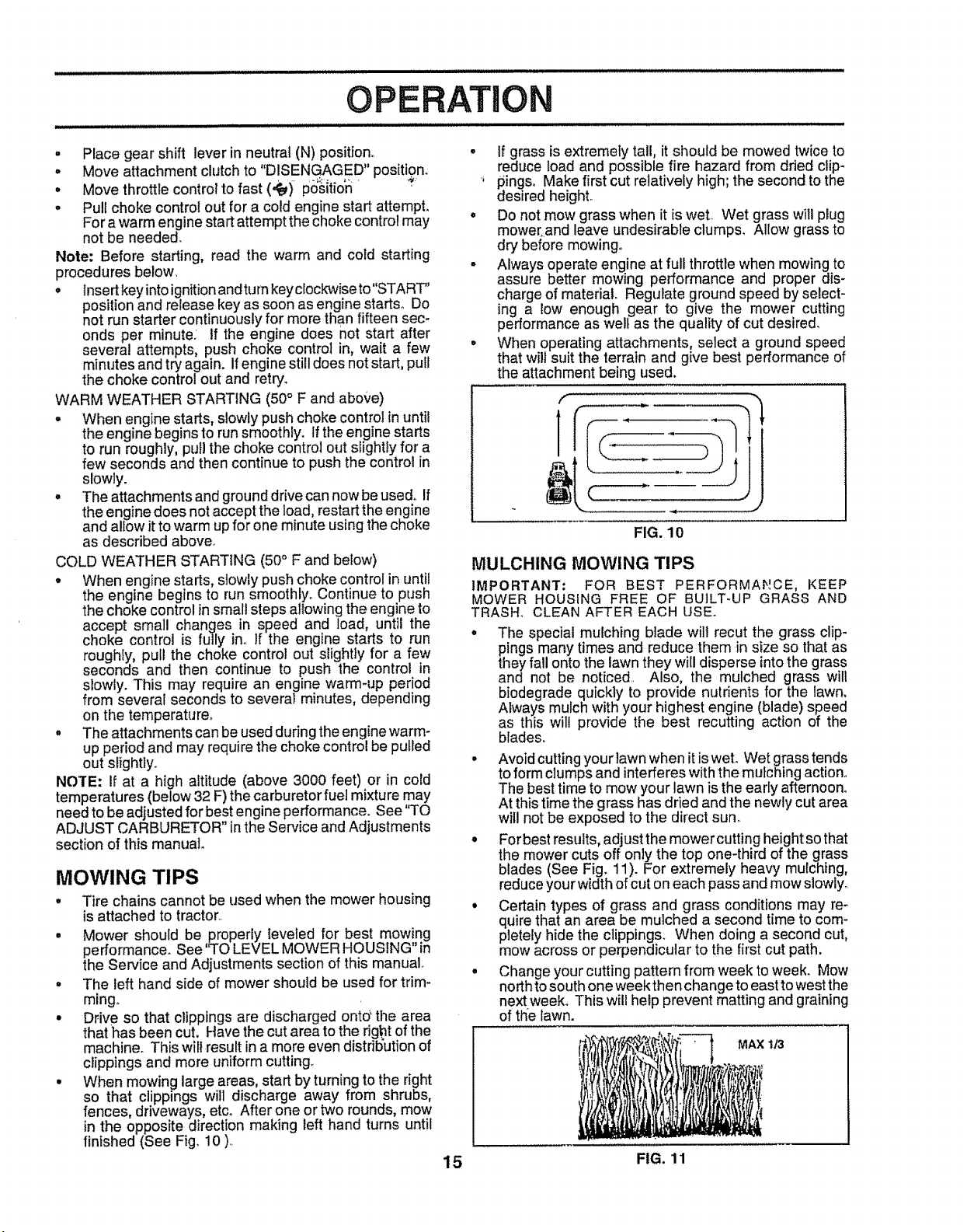
• When mowing large areas, start by turning to the right
so that clippings will discharge away from shrubs,
fences, driveways, etc. After one or two rounds, mow
in the opposite direction making left hand turns until
finished (See Fig,,10 ).,
If grass is extremely tall, it should be mowed twice to
reduce toad and possible fire hazard from dried clip-
pings. Make first cut relatively high; the second to the
desired height°
Do not mow grass when it is wet., Wet grass will plug
mower.and leave undesirable clumps. Allow grass to
dry before mowing.
Always operate engine at full throttle when mowing to
assure better mowing performance and proper dis-
charge of material. Regulate ground speed by select-
ing a low enough gear to give the mower cutting
performance as welt as the quality of cut desired.
When operating attachments, select a ground speed
that wilt suit the terrain and give best performance of
the attachment being used.
f
FIG. 10
MULCHING MOWING TIPS
IMPORTANT: FOR BEST PERFORMANCE, KEEP
MOWER HOUSING FREE OF BUILT-UP GRASS AND
TRASH. CLEAN AFTER EACH USE.
• The special mulching blade will recut the grass clip-
pings many times and reduce them in size so that as
they fall onto the lawn they will disperse into the grass
and not be noticed, Also, the mulched grass will
biodegrade quickly to provide nutrients for the lawn,
Always mulch with your highest engine (blade) speed
as this will provide the best recutting action of the
blades,
° Avoid cutting your lawn when it iswet. Wet grass tends
to form clumps and interferes with the mulching action°
The best time to mow your lawn is the early afternoon°
At this time the grass has dried and the newly cut area
will not be exposed to the direct sun.
• For bestresults, adjust the mower cutting height so that
the mower cuts off only the top one-third of the grass
blades (See Fig. 11). For extremely heavy mulching,
reduce your width of cut on each pass and mow slowly.
• Certain types of grass and grass conditions may re-
quire that an area be mulched a second time to com-
pletely hide the clippings. When doing a second cut,
mow across or perpendicular to the first cut path.
• Change your cutting pattern from week to week. Mow
northto south one week then change to east towest the
next week. This will help prevent matting and graining
of the lawn.
MAX 1/3
15 FIG. 11

CUSTOMER R ;IBILITIES
choc,E_gioeOilLevel V' _"
C'hange 'EngineOil _##
E CleanAir Filter ........ _#'2
N CleanAir Screen ............ V'2
G Inspect Muffler/SparkArrester
[ ReplaceOilFtlter(if equipped)
tie""Engine€oo"ngFi.s i
RepiaceSparkPlug
Replace Air Filter Paper Cartridge
Replace Fuel Filter
t - Change more often when operating under a heavy lead or inhigh ambient tempera{ures
2 - Service mote often when operating in dirty ordusty conditions
3 - tf equipped withoil fillet, change ottevery 50 hours
4 - Replace blades more often when mowing in sandy soR
GENERAL RECOMMENDATIONS
The warranty on this tractor does not cover-items that have
been subjected to operator-abuse or negligence. To
receive fuli value from the warranty,operator must maintain
tractor as instructed in this manual.
Some adjustments will need to be made periodically to
properly maintain your tractor,
All adjustments inthe Service and Adjustments section of
this manual should bechecked at Ieast once each season.
Once a year you should replace the spark plug, clean
or replace air filter, and check blades and belts for
wear° A new spark plug and clean air filter assure
proper air-fuel mixture and help you rengine run better
and last longer.
BEFORE EACH USE
- Check engine oil level.
, Check brake operation.
o Ch'eck tire pressure°
• Check for loosefasteners.
m m ,, ................
i ¸..... iv...... i ...........
v'
v'_
.......v' v'
v'2
Vw. i .........
5 - If equipped with,adjustable system
6 - Not requited if equipped with maintenance-tree battery
7. Tighlen f_'ontaxle pivot bolt to 35 Ii .-lbs maximum
Do net overtighten
LUBRICATION CHART
(_)SPINDLE ZERK (_)
(_) FRONT
BEARING ZERK
CLUTCH
PIVOT(S)
'(_SAE 30 OR 10W30 MOTOR OIL
_GENERAL PURPOSE GREASE
(_)REFER TO CUSTOMER RESPONSIBILITIES "ENGINE" SECTION
IMPORTANT; DO NOT OIL OR GREASE THE PIVOT POINTS
WHICH HAVE SPECIAL NYLON BEARINGS, VISCOUS LUBRI-
CANTS WILL ATTRACT DUST AND DIRT THAT WiLL SHORTEN
THE LIFE OF THE SELF-LUBRICATING BEARINGS. IF YOU
FEEL THEY MUST BE LUBRICATED, USE ONLY A DRY, Pew-
1 6 DERED GRAPHITE TYPE LUBRICANT SPARINGLY.
FRONT WHEEL(_
BEARING ZERK
PIVOTS
@
3)
CUSTOMER RESPONSiBIL ES
TRACTOR
Always observe safety ruleswhen perform!pg any ma[_!e-
nance_
BRAKE OPERATION
If tractor requires more than six (6) feet stopping distance
at high speed inhighest gear, then brake must beadjuste&
(See 'q'O ADJUST BRAKE" in the Service and Adjust-
ments section of this manual)°
TIRES
- Maintain proper air pressure in all tires (See "PROD-
UCT SPECIFICATIONS" on page 3 of this manual),,
• Keep tires free of gasoline, oil, or insect control chemi-
cals which can harm rubber.
• Avoid stumps, stones, deep ruts, sharp objects and
other hazards that may cause tire damage,,
BLADE CARE
For best results mower blades must be kept sharp, Re-
place bent or damaged blade&
BLADE REMOVAL (See Fig. 12)
- Raise mower to highest position to allow access to
blades°
- Remove hexbolt, lock washer and flat washer securing
blade°
. install new or resharpened blade with trailing edge up
towards deck as shown.
• Reassemble hex bolt, lock washer and flat washer in
exact order as shown.
. Tighten bolt securely (30-35 Ft..Lb& torque)..
IMPORTANT: BLADEBOLT ISGRADE 8 HEATTREATED_
NOTE: We do not recommend sharpening blade- but ifyou
do, be sure the blade is balanced_
MANDREL
ASSEMBLY
FLAT WASHER
LOCK WASHER
HEX BOLT
"A GI_IADE 8 HEAT TREATED BOLT CAN BE IDENTIFIED
BY SIX LINES ON THE BOLT HEAD,
FIG. 12
BLADE
TRAILING EDGE
/
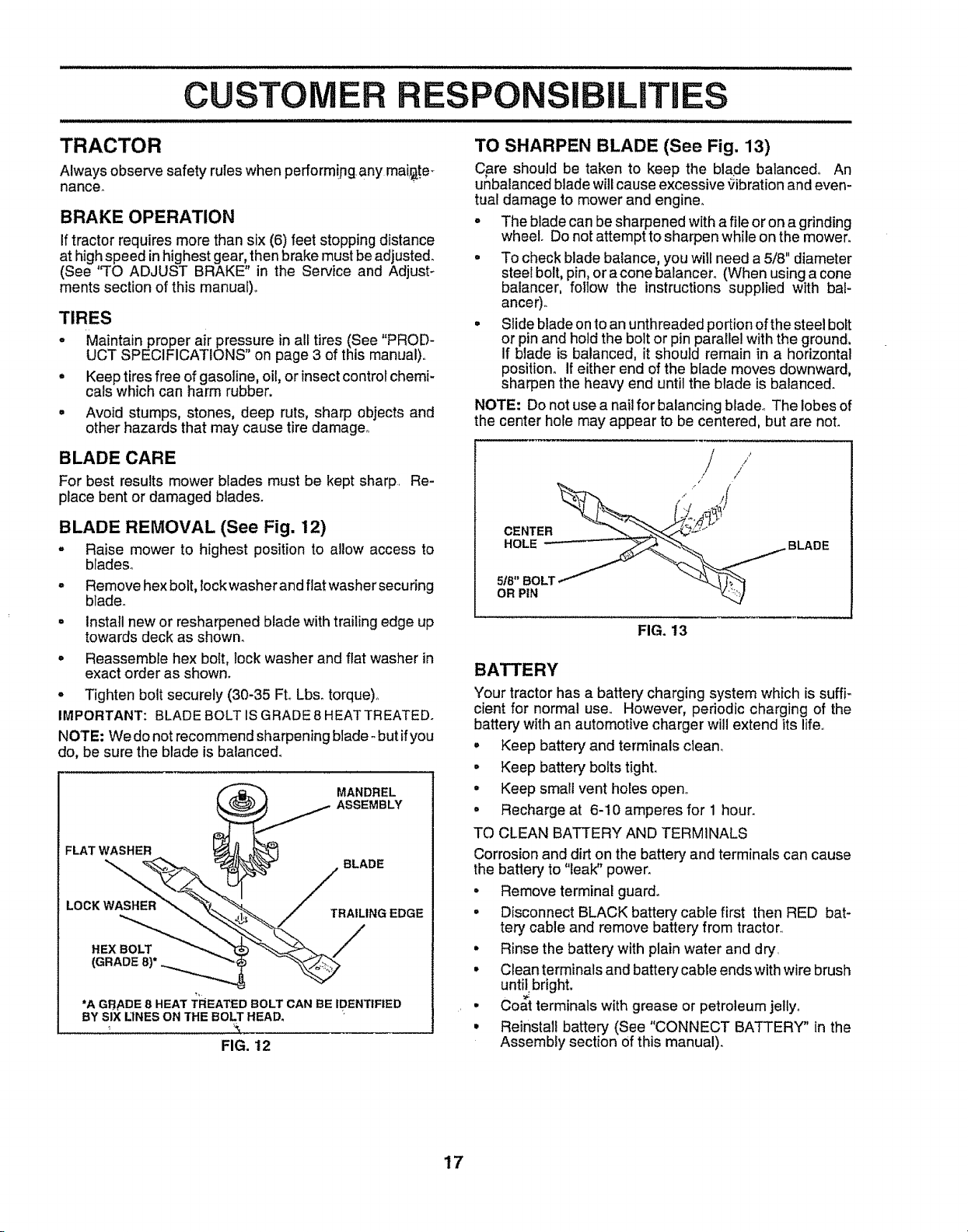
TO SHARPEN BLADE (See Fig. 13)
Care should be taken to keep the blade balanced° An
unbalanced blade will cause excessive gibration and even-
tual damage to mower and engine,.
• The blade can besharpened with a file or on a grinding
wheel. Do not attempt to sharpen while on the mower.
• To check blade balance, you will need a 5/8" diameter
steel bolt, pin, or a cone balancero (When using a cone
balancer, follow the instructions supplied with bal-
ancer).
• Slide blade onto an unthreaded portion ofthe steel bolt
or pin and hold the belt or pin parallel with the ground,
If blade is balanced, it should remain in a horizontal
position, If either end of the blade moves downward,
sharpen the heavy end until the blade is balanced.
NOTE: Do not use a nail for balancing blade_ The lobes of
the center hole may appear to be centered, but are noL
BLADE
OR PIN
FIG. 13
BATTERY
Your tractorhas a battery charging system which is suffF
cient for normal use,. However, pedodic charging of the
battery with an automotive charger will extend its life.
° Keep battery and terminals clean..
• Keep battery bolts tight.
• Keep small vent holes open.
o Recharge at 6-10 amperes for 1 hour.
TO CLEAN BATTERY AND TERMINALS
Corrosion and dirt on the battery and terminals can cause
the battery to "leak" power_
• Remove terminal guard.
• Disconnect BLACK battery cable first then RED bat-
tery cable and remove battery from tractor_.
° Rinse the battery with plain water and dry.
• Clean terminals and battery cable ends with wire brush
until,bright,
° Coat terminals with grease or petroleum jelly°
° Reinstall battery (See "CONNECT BATTERY" in the
Assembly section of this manual).
17
 Loading...