

Craftsman 917256610 Owner’s Manual
CR/ F
NUMB 917.256610
®Assembly
oOperation
=Customer Responsibilities
Service and Adjustments
, Repair Parts
OWNER'S MANUAL
CAUTION: Read and follow all safety rules and instructions before operating this equipment.
FOR CONSUMER ASSISTANCE HOT LINE, CALL THIS TOLL FREE NUMBER: 1-800-659-5917

Safe Operation Practices for Ride-On Mowers
IMPORTANT" THIS CUTTING MACHINE IS CAPABLE OF AMPUTATING HANDS AND FEET AND THROWING OBJECTS,,
FAILURE TO OBSERVE THE FOLLOWING SAFETY INSTRUCTIONS COULD RESULT IN SERIOUS INJURY OR DEATH+
SAFETY RULES
I. GENERAL OPERATION
• Read, understand, and follow all instructionsinthe manual
and on the machine before starting,
• Only allow responsible adults, who are familiar with the
instructions, to operate the machine+
,, Clear the area of objects such as rocks, toys, wire, etc.,
which could be picked up and thrown by the blade+
• Be sura the area isclear of other people before mowing. Stop
machine if anyone enters the area+
• Never carry passengers.,
° Do not mow in reverse unless absolutely necessary+ Always
look down and behind before and while backing+
• Be aware of the mower discharge direction and do not point
it at anyone+ Do not operate the mower without either the
entire grass catcher or the guard in place.
• Slow down before turning+
• Never leave a runningmachine unattended+ Always turn off
blades, set parking brake, stop engine, and remove keys
before dismounting..
• Turn off blades when not mowing+
• Stop engine before removing grass catcher or unclogging
chute.
• Mow only in daylight or good artificial light..
• Do not operate the machine while under the influence of
alcohol or drugs+
° Watch for traffic when operating near or crossing roadways+
• Use extra care when loading or unloading the machine into
a trailer or truck.
11. SLOPE OPERATION
Slopes are a major factor related to loss-of-control and
tipover accidents, which can result in severe injury ordeath+
All slopes require extra caution, tf you cannot back up the
slope or if you feel uneasy on it, do not mow it+
DO:
• Mow up and down slopes, not across.
• Remove obstacles such as rocks, tree limbs, etc.
• Watch for holes, ruts, or bumps. Uneven terrain could
overtum the machine+ Taftgrass can hide obstacles+
° Usestow speed_ Choose alow gear so thatyou willnot have
to stop or shift while on the slope.
• Follow the manufacturer's recommendations for wheel
weights or counterweights to Improve stability.
• Use extra care with grass catchers or other attachments.
These can change the stability of the machine+
• Keep all movement on the slopes slow and gradual. Do not
make sudden changes In speed or direction+
• Avoid starting or stoppingon a slope, if tires lose traction,
disengage the blades and proceed slowly straight down the
slope.
DO NOT:
* Donottumonslopesun[essnecessary, andthen, tumslowly
and graduallydownhill, if possible_
* Donotmow near drop-offs, ditches, or+embankments+"['he
mower could suddenly turn over if a whe_l ts over the edge
of a cliffOrditch, or if an edge caves in.
Do not mow on wet grass+ Reduced traction could cause
sliding.
. Donot tryto stabilize the machine by puttingyour foot on the
ground.
• Do not use grass catcher on steep slopes+
I!L CHILDREN
Tragic accidents can occur if the operatoris not alert to the
presence of children+ Children are often attracted to the
machine and the mowing activity. Never" assume that
children will remain where you last saw them+
• Keepchildrenout ofthe mowing area and underthewatchful
care qf another responsible adult,
• Be alert and rum machine off if children enter the area+
• Before and when backing, look behind and down for small
children+
• Never carry children. They may fall off and be seriously
injured or interfere with safe machine operation+
° Never allow childrento operate the machine,
• Use extra care when approaching blind comers, shrubs,
trees, or other objects that may obscure vision.
IV. SERVICE
• Use extracarein hand[inggasoline and otherfuels. Theyare
flammable and vapors are explosive+
Use only an approved container.
Never remove gas cap or add fuel with the engine
running+ Allow engine to cool before refueling+ Do not
smoke.
Never refuel the machine indoors+
Never store the machine or fuel container inside where
• Never run a machine inside a closed area.
• Keep nuts and bolts, especially blade attachment bolts, tight
° Never tamper with safety devlceso Check their proper
. Keep machine free of grass, leaves, or other debris build-up.
• Stop and inspect the equipment if you strike an object.
• Never make adjustments or repairs with the engine running.
• Grass catcher components are subjectto wear, damage, and
. Mower blades are sharp and can cut+ Wrap the blade(s) or
• Check brake operation frequently. Adjust and service as
i Ul I IIIJIIlUll
there is an open flame, such as a water heater+
and keep equipment in good condition+
operation regularly+
Clean oil or fuel spillage+ Allow machine to cool before
stodng°
Repair, if necessary, before restarting+
deterioration, which could expose moving parts or allow
objects to be thrown. Frequently check components and
replace with manufacturer's recommended parts, when nec-
essary+
wear gloves, and use extra caution when servicing them.
required.
,,, ,,,,,,,,,,,,,,,,,,,,
portant safety precautions. It means
Look for this symbol to point out im-
CAUTION[!t BECOME ALERTII! YOUR
SAFETY IS INVOLVED.
I II ii ii
CAUTION: Always disconnect spark plug
wlre and place wire where It cannot contact
&
iiiull iiii iii
spark plug In order to prevent accidental
sterting when setting up, transporting,
adjusting or making repairs+
A WARNING
The engine exhaust from this product con-
tains ctiemicals known to the State of Califor-
nia to cause cancer, birth defects, or other
reproductive harm.

CONGRATULATIONS on your purchase of a Sears
tractor. It has been designed, engineered and manufac_
tured to give you the best possible dependability and
performance.
Should you experience any problem you cannot easily
remedy, please contact your nearest Sears Service Cen-
ter/Departmento We have competent, well-trained tech-
nicians and the proper tools toservice or repair-thistrac-
toro
Please read and retaLnthis manual The instructionswill
enable you to assemble and maintain your tractor prop-
erly. Always observe the SAFETY RULES".
MODEL
NUMBER 917.25266'10
PRODUCT SPECIFICATIONS
HORSEPOWER: 15.5
GASOLINE CAPACITY 3_5GALLONS
AND TYPE: UNLEADED REGULAR
OIL TYPE (API-SFtSG): SAE 10W-30 (above 32°F)
SAE 5W-30 (below 32°F)
OIL CAPACITY: Wi FILTER: 4_0 PINTS
W/O FILTER: 3.5 PINTS
SPARK PLUG: CHAMPION RC12YC
(GAP: °040")
VALVE CLEARANCE: NOT ADJUSTABLE
SERIAL
NUMBER
DATE OF PURCHASE
THE MODEL AND SERIAL NUMBERS WILL BE FOUND
ON A PLATE UNDER THE SEAT°
YOU SHOULD RECORD BOTH SERIAL NUMBER AND
DATE OF PURCHASE AND KEEP INA SAFEPLACE
FOR FUTURE REFERENCE,.
MAINTENANCE AGREEMENT
A Sears maintenance agreement is available on this prod-
ucto Contact your nearest Sears store for details°
CUSTOMER RESPONSIBILITIES
o Read and observe the safety rules.
o Follow a regular schedule in maintaining, caring forand
using your tractor.
o Followthe instructions under "Customer Responsibili-
ties" and "Storage" sections of this owner's manual.
GROUND SPEED (MPH): FORWARD: 5.5
TIRE PRESSURE: FRONT: 14 PSI
CHARGING SYSTEM: 3 AMPS BATTERY
BATTERY: AMP/HR: 30
BLADE BOLT TORQUE: 30-35 FT. LBS.
REVERSE: 24
REAR: 10 PSI
5 AMPS HEADLIGHTS
MINo CCA: 240
CASE SIZE: U1R
WARNING: This tractor is equipped with an internal
combustion engine and should not be used on or near any
unimproved forest-covered, brush-covered or grass-cov-
ered land unless the engine's exhaust system is equipped
with a spark arrester meeting applicable local or state laws
(ifany)° If a spark arrester isused, it should be maintained
in effective working order by the operator.
in the state of California the above is required by law
(Section 4442 of the California Public Resources Code)°
Other states may have similar la,#so Federal laws apply on
federal lands° A spark arrester for the muffler is available
throuqh your nearest Sears Authorized Service Center
(See REPAIR PARTS section of this manual).
LIMITED TWO YEAR WARRANTY ON CRAFTSMAN RIDING EQUIPMENT
For two (2) years from the date of purchase, ifthisCraftsman Riding Equipment is maintained, lubricated and tuned up according
to the instructionsin the owner's manual, Sears witl repair or replace, free of charge, any parts found to be defective in matedal
or workmanship.
This Warrant,/does not cover:.
• Expendable items which become worn during normal use, such as blades, spark plugs, air cleaners, belts, etc_
° Tire replacement or repair caused by punctures from outside objects, such as nails, thorns, stumps, or glass.
• Repairs necessary because of operator abuse, negligence, improper storage or accident or the failure to maintain the
equipment according to the instructions contained in the owner's manual.
o Riding equipment used for commercial or rental purposes.
LIMITED 90 DAY WARRANTY ON BATTERY
For ninety (90) days from date of purchase, if any battery included with this riding equipment proves defective in material or
workmanship and our testing determines the battery wiIi not hold a charge, Sears witl replace the battery at no charge°
IN-HOME WARRANTY SERVICE ON YOUR CRAFTSMAN RIDING EQUIPMENT IS AVAILABLE AT NO-CHARGE FOR 30
DAYS FROM THE DATE OF PURCHASEr PLEASE CONTACT YOUR NEAREST SERVICE CENTER. AFTER 30 DAYS
LFROM THE DATE OF PURCHASE, WARRANTY SERVICE IS AVAILABLE BY TAKING YOUR CRAFTSMAN RIDING EQUIP"
MENT TO YOUR NEAREST SEARS SERVICE CENTER. (IN"HOME WARRANTY SERVICE WILL STILL BE AVAILABLE
AFTER 30 DAYS FROM THE DATE OF PURCHASE BUT A STANDARD TRIP CHARGE WILL APPLY_) THIS WARRANTY
APPLIES ONLY WHILE THIS PRODUCT IS IN THE UNITED STATES°
This Warranty gives you specific legal rights, and you may also have other rights which may vary from state to state_
SEARS, ROEBUCK AND CO., D/817 WA, HOFFMAN ESTATES, IL 60179
3

LI...................
i iii iiiiii Ill IIII ............ I1|
TABLE OF CONTENTS
SAFETY RULES ............................................................ 2
PRODUCT SPECIFICATIONS ...................................... 3
CUSTOMER RESPONSIBILITIES .......................3, 16-19
WARRANTY .................................................................. 3
TRACTOR ACCESSORIES .......................................... 5
ASSEMBLY ............................................................. 7-10
OPERATION .......................................................... 11-16
INDEX
A
Accessories ...................................................5
Adjustments=
Brake ..................................................24
Carburetor ...............................................27
Mower
Front-To-Back ........................... 22
Side-To-Side .................................22
Throttle ControlCable .........................27
Air Filter, Engine...............................................20
Air Screen, Engine ....................................."19
Assembly .....................................................7.70
B
Battery:
Charging ............................................8
Cleaning ............................................18
Stading with Weak Battery .......... 26
Storage ...................................................28
Terminals ....................................... 18
Belt:
Motion Drive
RemovaVReplacement ........... 24
Mower Belt(s)
RemovaVReplacement ...............23
Blade:
Sharpening ...................................................18
Replacement .........................................18
Brake Adjustment ................................ 24
C
Carburetor Adjustment .................................27
Controls, Tractor ..........................................t2
Customer Responsibilities ............. 17-20
Engine:
Air Filter........................................20
Air Screen .................................. i9
Cooling Fins ................................20
Engine Oft ............................. 15,19
Fuel Filter .....................................20
Spark Plug(s) .................................20
Tractor,
Battery...................................................18
Blade ......................................... 18
LubricationChart ...................... 17
Maintenance Schedule ............ !7
Tire Care o._........................ 8,18,25
TransaxJe,,,,._................................ 19
Cutting Height, Mower ..............................13
E
Electrical:
interlocks and Relays ..........................26
Schematic ..................................:........... 31
Wiring Diagram ................................32
Engine:
Air Filter............................................20
Air' Screen ..................................................19
Cooling Fins ......................................20
Oil Change ........................................!9
Ol_Level ..............................................19
Oil Type ....................................................15,19
Preparation ............... _:_.ii.................15
Repair Parts ......................................50-55
Starting........................................................15
Storage ......................................................28
Fiitet:
Air' Filter.................................................20
Fuel.......................................................20
Fuel:
Type ..............................................................15
Storage ........................................................28
Fuse ....................................................................26
Hood RemovaVInstallation ......................26
Leveling Mower' Deck .........................................22
Lubrication:
Chart .............................................. t7
Engine..............................................19
Maintenance Schedule ...............................17
Mower:
Adjustment, Front-to-Back ................22
Adjustment, Side-to-Side .............. 22
Blade Replacement ...........................18
Blade Sharpening .............................18
Cutting Height ...........................................t3
installation ....................................... 29
Operation ..................................... 14
Removal ..................................................21
Mowing Tips ..................................................16
Muffler. ....................................................20
Spark Arrester ...................................3,40
0t1:
Cold Weather Conditions ......... 15,1
Engine...............................................19
Storage .............................................28
MAINTENANCE SCHEDULE ..................................... 17
SERVICE AND ADJUSTMENTS ........................... 21-27
STORAGE ................................................................... 28
TROUBLESHOOTING ........................................... 29-30
REPAIR PARTS - TRACTOR ................................ 32-49
REPAIR PARTS - ENGINE .................................... 50-55
PARTS ORDERINGJSERVtCE ............... BACK COYER
Operation .............................................12-t6
Operating Mower .................................. t4
Options:
Accessodes ............................................5
Spark Arrestor ..................................3,40
P
Parking Brake ........................................... 12-13
Parts Bag ......................................................6
Parts, Replacement/Repair ...............32-49
F
Product Specifications ..............................3
R
Repair Parts ................................... 32-55
S
Safety Rules ................................................2
Seat ..................................................................8
H
L
M
O
Service and Adjustments .................21-27
Carburetor .........................................27
Fuse ................................................ 26
Hood Removal/Installation ........... 26
Motion Ddve Belt
Removal/Replacement ........... 24
Mower Belt(s)
Removal]Replacement ........... 23
Mower Adjustment
Front-to-Back ...............................22
Side-to-Side ............................ 22
Mower Removal]Installation ......... 21
Tire Care ........................................8,18,25
Slope Guide Sheet ............................... 59
Spark Plug(s) ...........................................20
Specifications .............................................3
Starting the Engine ............................... 15
Steering Wheel .................................. 7,25
Stopping the Tractor .................................. 13
Storage .................................................... 28
T
Throttle Control Cable Adjustment .......27
Tires.............................................. 8,18,25
Trouble Shooting Chart .................... 29-30
Transaxle ..................................................19
J W
Warranty ...........................................................3
Wiring Diagram .........................................32
Wiring Schematic ....................................31
4
ACC ruES ATTACHMENTS
i i,,i,H
These accessories and attachments were available through most Sears retail out_etsand service centers when the tractor was purchased_
Most Sears stores can order these items for you when you provide the model number of your tractor,
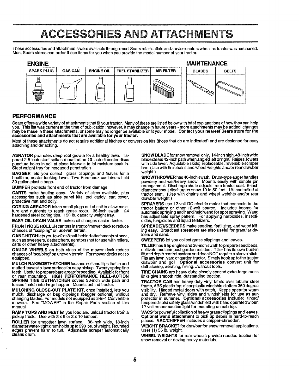
ENGINE MAINTENANCE
SPARK PLUG BLADES BELTSGAS CAN ENGINEOIL FUELSTABILIZER AIR FILTER
%
PERFORMANCE
Sears offersa wide variety of attachments thatfit yourtractor° Many of,these are listedbelowwithbrief explanations of howthey can help
you° This list was current at the time of publication;however, itmay change in futureyears - more attachments may be added, changes
may be made in these attachments, or some may no longer be available or fit your model° Contact your nearest Sears store for the
accessories and attachments that are available for your tractor.
Most of these attachments do not require additionalhitches or conversion kits (those that do are indicated) and are designed for easy
attaching and detaching.
AERATOR promotes deep root growth for a healthy lawno Ta-
pered 2.5-inch steel spikes mounted on 10-inch diameter discs
puncture holes in soil at close intervals to let moisturesoak ino
Steel weight tray for increased penetration,
BAGGER lets you collect grass clippings and leaves for a
healthier, neater looking lawno Two Permanex containers hold
30-gallon plastic bags°
BUMPER protects front end of tractor from damage,
CARTS make hauling easy Variety of sizes available, plus
accessories such as side panel kits, tool caddy, cart cover,
protective mat and dolly.
CORING AERATOR takes small plugs out ofsoilto allow mois-
ture and nutrients to reach grass roots, 36-inch swath. 24
hardened steel coringtips. 150 lb.,capacity weight tray.
EASY OIL DRAIN VALVE makes oil changes easier, faster°
FRONT NOSE ROLLER canters infront of mower deck to reduce
chances of "scalping" on uneven terrain.
GANG HITCH lets you tow 2 or 3 pull-behlnd attachments at once,
such as sweepers, dethatchers, aerators (not for use with rollers,
carts or other heavy attachments).
GAUGE WHEELS on both sides of the mower deck reduce
chancesof "scalping"on uneven terrain. Formowerdecksnotso
equipped.
MULCH RAKE/DETHATCHER loosens soil and flips thatch and
matted leavesto lawn surface foreasy pickup° Twenty spring tine
teeth,, Useful to prepare bare areas for seeding. Available for front
or rear mounting, HIGH PERFORMANCE REEL-ACTION
SPRING TINE DE'THATCHER covers 36-inch wide path and
tosses thatch into large hopper. Mounts behind tractor,
MULCHING CLOSE-OUT PLATE KIT, once installed, lets you
mulch, discharge or bag clippings (bagger optional) without
changing blades. For models not equipped as 3-in-t Convertible
mowers. See "MOWER" in the Repair Parts section of this
manual.
RAMP TOPS AND FEET let you load and unload tractor fi'orh a
.pickup truck.. Use with 2 x 8 or 2 x 10 lumber.
ROLLER for smoother lawn surface. 36-inch wide, 18-1nch
'diameter wateroflght drum holds up to 390 lbs.of weight. Rounded
edges prevent harm to tuff. Adjustable scraper automatically
cleans drum.,
SNOW BLADEforsnow removal only. 14-inch high, 48-inch wide
blade clears42-inch pathwhen angled leftor right. Raises, lowers
withside lever=Adjustable skids; replaceable, reversible scraper
bar. (Use withtirechains and wheel weights and/or rear drawbar
weighL)
SNOWTHROWER has40-inch swath° Drum-type augerhandles
powdery and wet/heavy snow° Mounts easily with simple pin
arrangement,, Discharge chute adjusts from tractor seat° 6-inch
diameter spout discharges snow 10 to 50 feet, Lift controlledat
tractor seat. (Use with chains and wheel weights and/or rear
drawbar weighL)
SPRAYERS use 12wolt DC electric motor that connects to the
tractor battery or other 12-voft source Includes booms for
automaticspraying and hand held wand for spotspraying. Wand
has adjustable spray pattern, For applying herbicides, insecti-
cides,fungicides and liquidfertilizers.
SPREADER/SEEDERS make seeding,fertilizing, and weed kill-
ing easy. Broadcast spreaders are also useful for granular de-
icers and sand.
SWEEPERS let you collect grass clippings and leaves.
TILLER has 5 hp engineand 36-inch swath to prepare seed beds,
cullivate and compost garden residue. Tiller has itsown buitFin
lift and depth control system and doesNOT require asleeve hitch.
Fits any lawn, yard or garden tractoro Simply hook up tothe tractor
drawbar and go! Optlonai accessories convert unit for
dethatching, aerating, hilling.,..withouI tools,
TIRE CHAINS are heavy duty; closely spaced extra-large cross
links give smooth ride, outstanding traction,
TRACTOR CAB has heavy duty vinyl fabric over tubular steel
frame, ABS plastic top; clear plasticwindshield offers 360 degree
visibility. Hinged metal doors with catch, Keeps operator warm
and dry. Remove vinyl sides and windshields for use as sun
protector in summer. Optional accessories include: tinted/
tempered solid safety glass windshield with hand operated wiper;,
12-volt amber caution light for mounting on cab top.
VACS for power[Hi collection of heavy grass clippings and leaves.
Optional wand _attachment to pick up debns inhard-to-reach
places, VAC/CHIPPER includes a chipper-shredder.
WEIGHT BRACKET for drawbar for snow removal applications.
Uses (I) 55 Iboweight,
WHEEL WEIGHTS for rear wheels provide needed traction for
snow removal or dozing heavy materials.
5
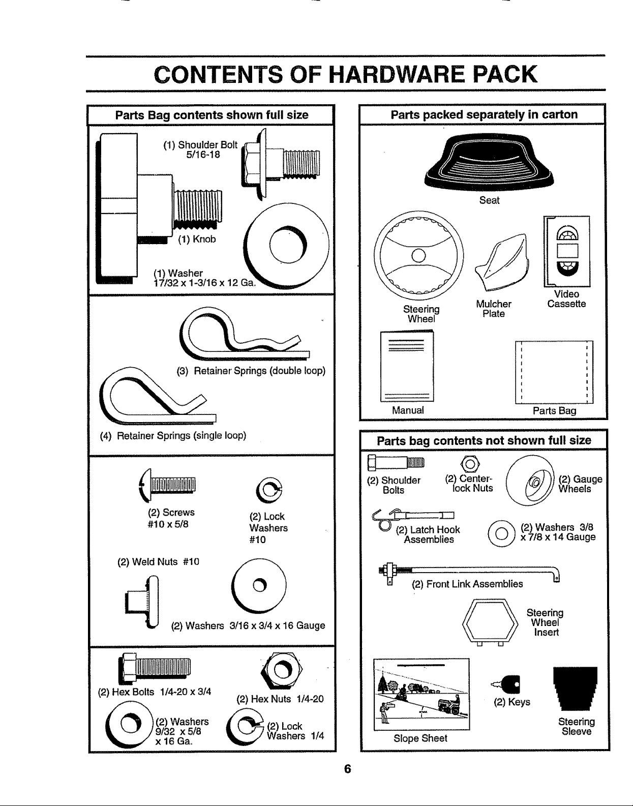
CONTENTS OF HARDWARE PACK
i1,1,iu,i,1, i,
Parts Bag contents shown full size
(I) Shoulder Bolt
5/16-18
(1) Knob
(1) Washer
17/32 x 1-3/16 x 12
i '11 IIIIIIIIJLIIgjIIIII
J I II II IIII UIIUIII
Parts packed separately in carton
Seat
Steering Plate
Wheel
Mulcher
Video
Cassette
:,illlllll
t
(4) Retainer Springs (single loop)
(2) Screws (2) Lock
#10 x 5/8 Washers
(2) Weld Nuts #10
(2) Washers 3/16 x 3/4 x 16 Gauge
!ijiinlliliillltllt{1il
(2) Hex Bolts 1/4-20 x 3/4
(2) Washers
9132 x 5/8
x 16 Gao
#10
(2) Hex Nuts t/4-20
(2) Lock
Washers 1/4
Manual
ii =i=l=,=ll_ ,i HII,iii 11,11,, :
Parts bag contents not shown full size
(2) Shoulder (2) Center:
Bolts lock Nuts
Parts Bag
Wheels
Hook
Assemblies
_="=_(2) Front Link Assemblies
Slope Sheet
x 7/8 x 14 Gauge
2) Washers 3/8
Steering
Wheel
(2) Keys
Insert
Steering
2) Gauge
Sleeve
6
BLY
Your new tractor has been assembled at the factory with exception of those parts left unassembled for shipping purposes.
To ensure safe and proper operation of your tractor, all parts and hardware you assemble must be tightened securely. Use
the correct tools as necessary to insure proper tightness_
TOOLS REQUIRED FOR ASSEMBLY
A socket wrench set will make assembly easier. Standard
wrench sizes are listed.
(1) 9/16" wrench (2) 7/16" wrench
(1) 1/2" wrench (1) 3/4" socket w/drive
Utility knife ratchet
Tire pressure gauge
When right and left hand is mentioned in this manuai, it
means when you are in the operating position (seated
behind the steering wheel).
TO REMOVE TRACTOR FROM CARTON
UNPACK CARTON
, Remove a!l accessible loose paTtsand parts cartons
from carton (See page 6).
, Cut, from top to bottom, along lines on all four corners
of carton, and lay panels flaL
° Check for any additional loose parts or cartons and
remove.
BEFORE ROLLnNG TRACTOR OFF
SKID
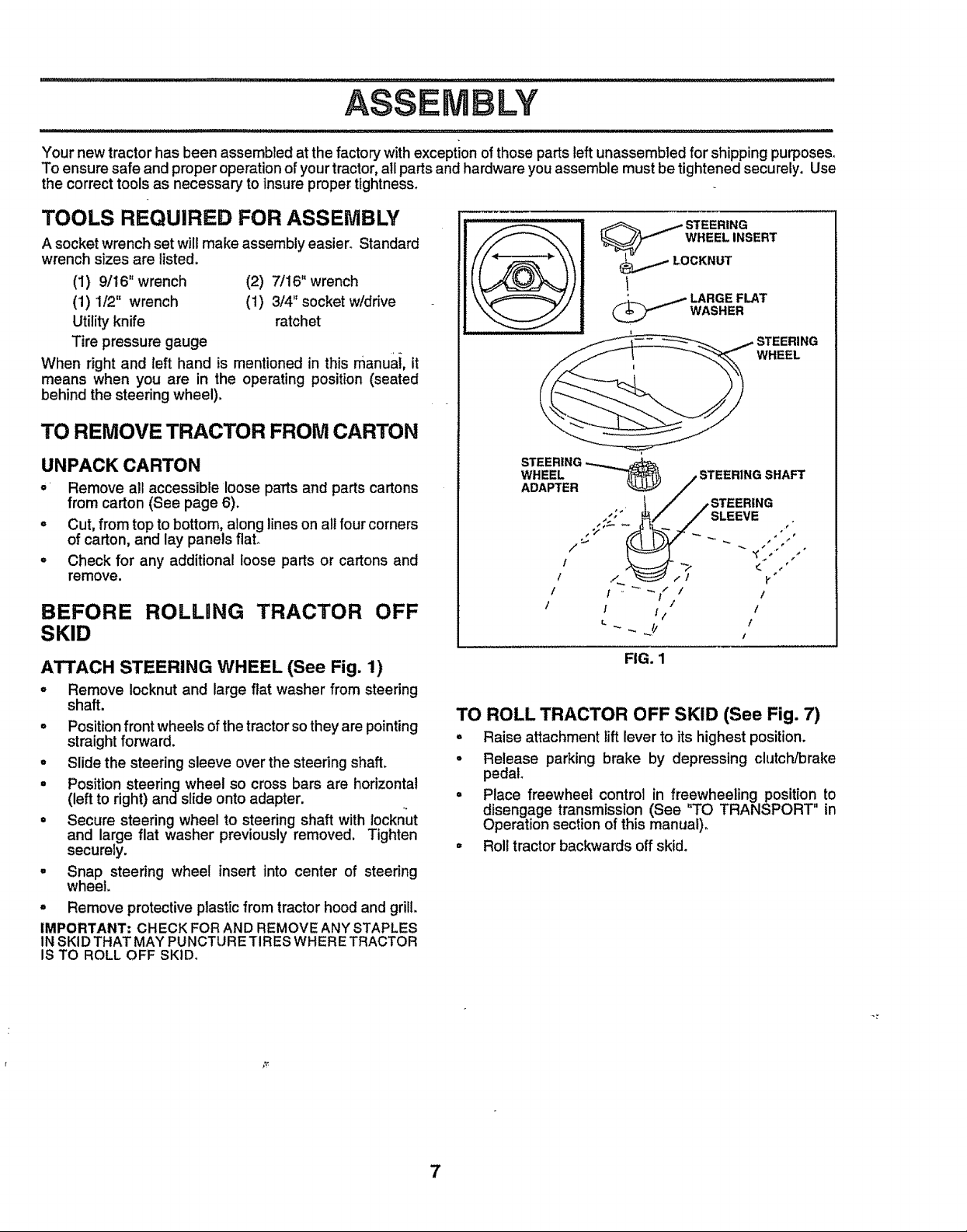
ATTACH STEERING WHEEL (See Fig. 1)
, Remove Iocknut and large flat washer from steering
shaft.
° Position front wheels of the tractor so they are pointing
straight forward.
° Slide the steering sleeve over the steering shaft.
° Position steering wheel so cross bars are horizontal
(left to right) andstide onto adapter.
° Secure steering wheel to steering shaft with locknut
and large flat washer previously removed. Tighten
securely.
° Snap steering wheel insert into center of steering
wheel.
° Remove protective plastic from tractorhood and grill.
IMPORTANT: CHECK FOR AND REMOVE ANY STAPLES
1NSKID THAT MAY PUNCTURE TIRESWHERE TRACTOR
IS TO ROLL OFF SKID.
_ ARGE FLAT
/ i . _/ /
/ i ii / /
FIG. 1
TO ROLL TRACTOR OFF SKID (See Fig. 7)
° Raise attachment lift lever to its highest position.
• Release parking brake by depressing clutch/brake
pedal
• Place freewheel control in freewheeling position to
disengage transmission (See "TO TRANSPORT" in
Operation section of this manual).
° Roll tractor backwards off skid.
WASHER
I"
I /
1
7
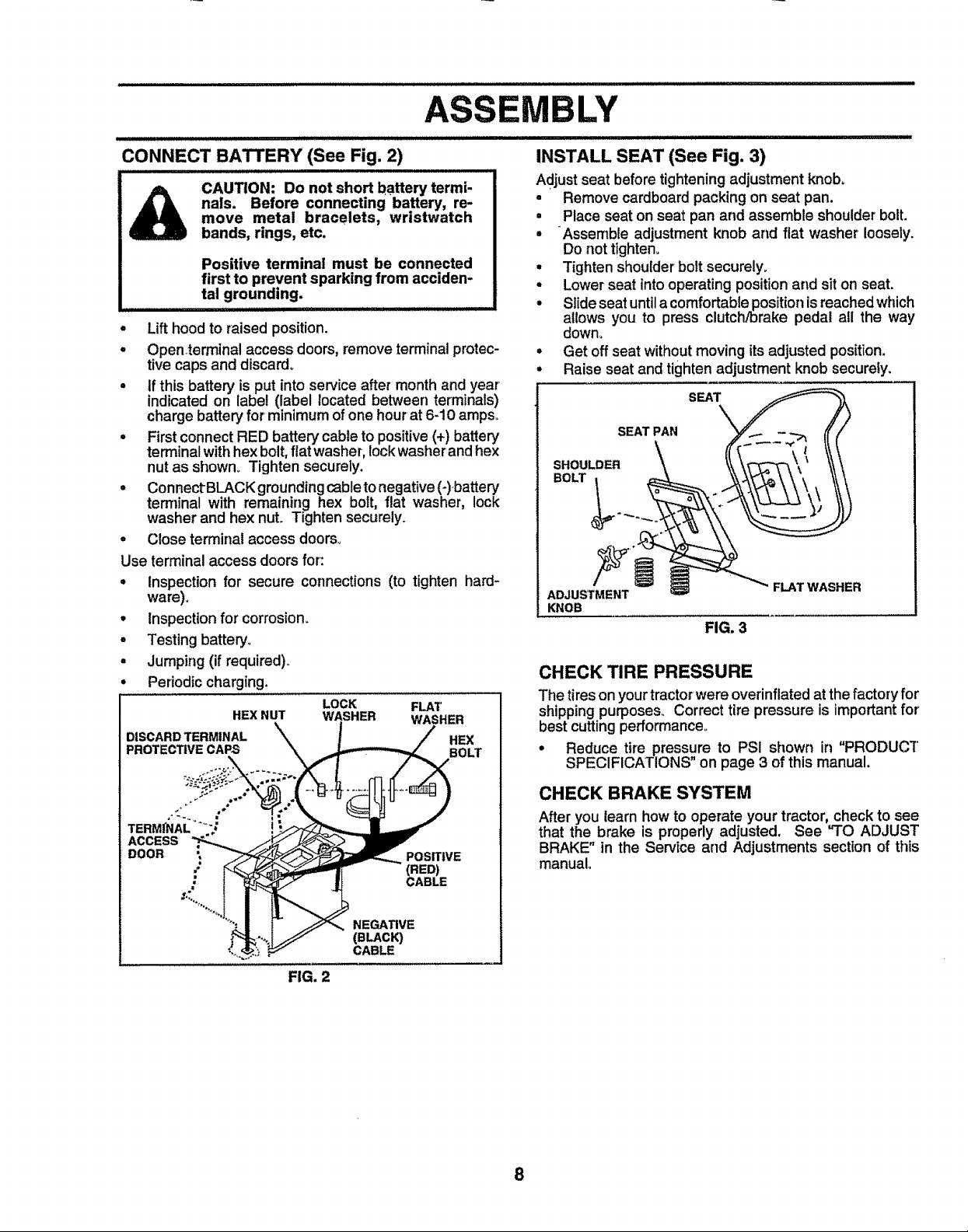
CONNECT BATTERY (See Fig. 2)
CAUTION: Do not short battery termi-
nals. Before connecting battery, re-
move metal bracelets, wristwatch
bands, rings, etc.
Positive terminal must be connected
first to prevent sparking from acciden-
tal grounding.
I II I IIIIIIIIIIIIIIII IJBI
• Lifthood to raised position.
° Openterminal access doors, remove terminal protec-
tive caps and discard°
• If this battery is put into service after month and year
indicated on label (label located between terminals)
charge battery for minimum of one hour at 6-10 ampso
• First connect RED battery cable to positive (+) battery
terminal with hex bolt, fiat washer, lock washer and hex
nut as shown_ Tighten securely,
° Connect BLACKgroundingcabletonegative (-),battery
terminal with remaining hex bolt, flat washer, lock
washer and hex nut Tighten securely
° Close terminal access doors°
Use terminal access doors for:
° Inspection for secure connections (to tighten hard-
ware).
• inspection for corrosion.
° Testing battery,,
• Jumping (if required),,
Periodiccharging.
LOCK FLAT
HEX NUT WASHER WASHER
DISCARD TERMINAL ""\ _ HEX
PROTECTIVE CAPS "\ _ -_'---_E BOLT
INSTALL SEAT (See Fig. 3)
Adjust seat before tighteningadjustment knob,
• Remove cardboard packing on seat pan.
• Place seat on seat pan and assemble shoulder bolt
° Assemble adjustment knob and flat washer loosely
Do not tighten,
• Tighten shoulder bolt securely,
° Lower seat intooperating position and sit on seat
° Slide seat until a comfortable position is reached which
allows you to press clutch/brake pedal all the way
down,
° Get off seat without moving its adjusted position.
• Raise seat and tighten adjustment knob securely,
SEAT PAN ...- - -- /
SEAT _1
.oo oo.\ ',
ADJUSTMENT _ _ _" FLAT WASHER
KNOB
FIG. 3
CHECK TIRE PRESSURE
The tireson yourtractorwere overinflated at thefactory for
shipping purposes° Correct tire pressure is importantfor
best cutting performance°
° Reduce tire pressure to PSI shown in "PRODUCT
SPECIFICATIONS on page 3 of this manual.
TERMfNAL: !_
ACCESS_ _y_/J_
.OOR i "o mvE
.,* _:--_'_ - (RED)
._ I'_ j CABLE
".............. o
j_:...._ (BL_CK_
_.o.'_,i__ CABLE
FIG. 2
CHECK BRAKE SYSTEM
After you learn how to operate your tractor, check to see
that the brake is properly adjusted. See "TO ADJUST
BRAKE" in the Service and Adjustments section of this
manual
8
LY
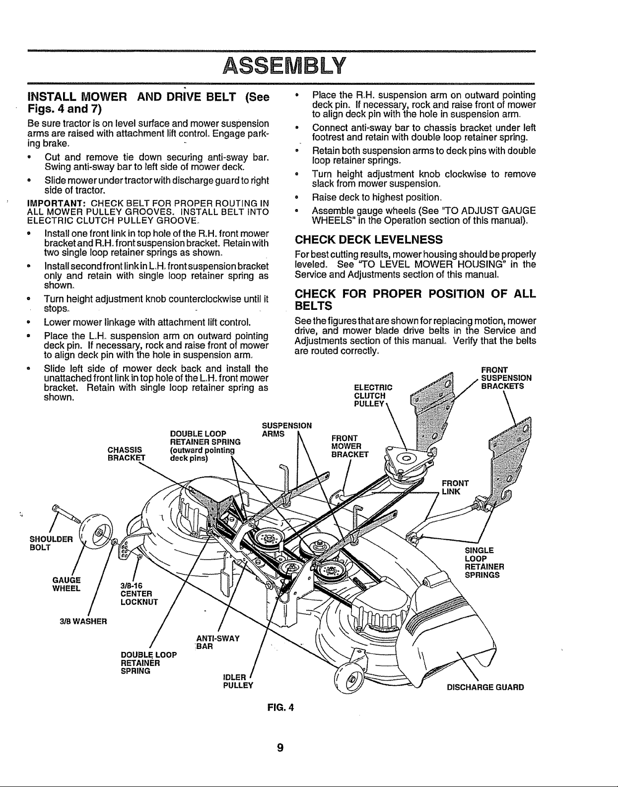
INSTALL MOWER AND DRIVE BELT (See
Figs. 4 and 7)
Be sure tractoris on level surface and mower suspension
arms are raised with attachment lift control° Engage park_
ing brake,
• Cut and remove tie down securing anti-sway bar,
Swing anti-sway bar to left side of mower deck,
• Slide mower under tractor with discharge guard to right
side of tractor.
IMPORTANT: CHECK BELT FOR PROPER ROUTING IN
ALL MOWER PULLEY GROOVES. INSTALL BELT INTO
ELECTRIC CLUTCH PULLEY GROOVE_
• Install one front link intop hole of the R,H. front mower
bracket and R.H, front suspension bracket. Retain with
two single loop retainer springs as shown.
° Install second front link in L,H,front suspension bracket
only and retain with single loop retainer spring as
shown_
o Turn height adjustment knob counterclockwise until it
stops°
• Lower mower linkage with attachment lift control.
= Place the LoHosuspension arm on outward pointing
deck pin, tf necessary, rock and raise front of mower
to align deck pin with the hole in suspension arm°
° Slide left side of mower deck back and install the
unattached front link intop hole of the L_H.front mower
bracket. Retain with single loop retainer spring as
shown.
SUSPENSION
DOUBLE LOOP
RETAINER SPRING
CHASSIS (outward pointing
BRACKET deck pins)
ARMS
° Place the R_H.suspension arm on outward pointing
deck pin. tf necessary, rock and raise front of mower
to align deck pin with the hole in suspension arm.
° Connect anti-sway bar to chassis bracket under left
footrest and retain with double loop retainer spring.
° Retain both suspension arms to deck pins with double
loop retainer springs,
= Turn height adjustment knob clockwise to remove
slack from mower suspension,,
° Raise deck to highest position.
• Assemble gauge wheels (See "TO ADJUST GAUGE
WHEELS" in the Operation section of this manual),
CHECK DECK LEVELNESS
For best cutting results, mower housing should be properly
leveled. See "TO LEVEL MOWER HOUSING" in the
Service and Adjustments section of this manual,
CHECK FOR PROPER POSITION OF ALL
BELTS
See the figuresthat are shown for replacing motion, mower
drive, and mower blade drive belts in the Service and
Adjustments section of this manual, Verify that the belts
are routed correctly.,
FRONT
SUSPENSION
ELECTRIC
CLUTCH
PULLEY \\
FRONT
MOWER
BRACKET
BRACKETS
SHOULDER
BOLT
GAUGE
WHEEL
_SWASHER
FRONT
LINK
SINGLE
LOOP
RETAINER
SPRINGS
3/8-16
CENTER
LOCKNUT
/
ANTI-SWAY
DOUBLE LOOP
RETAINER
SPRING
BAR
IDLER /
PULLEY
DISCHARGEGUARD
FIG. 4
9
......... j i LJ I I J ill Ill lllllH I II Ill Illlllll,,
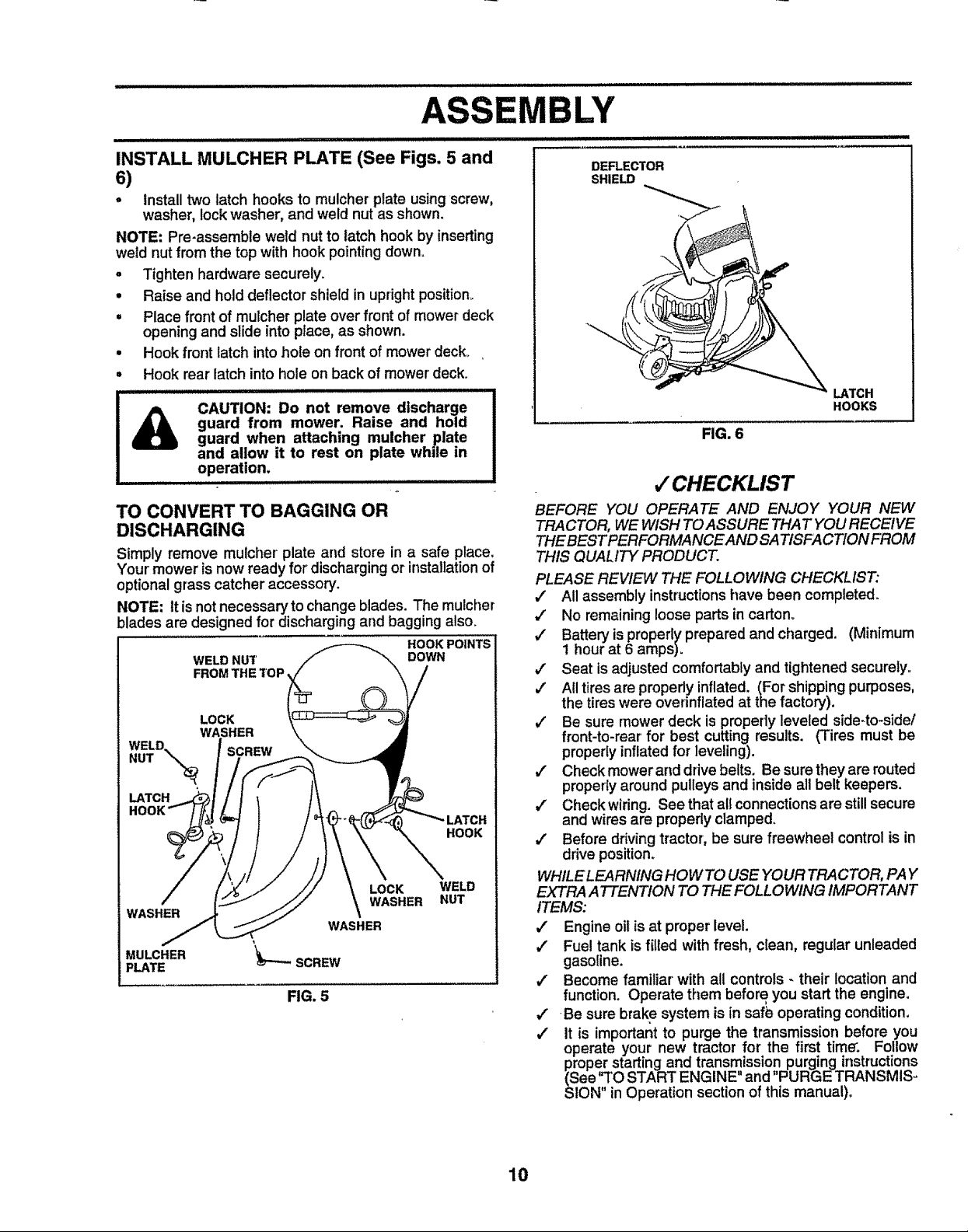
INSTALL MULCHER PLATE (See Figs. 5 and
6)
• Install two latch hooks to mulcher plate using screw,
washer, lock washer, and weld nut as shown.
NOTE: Pre-assemble weld nut to latch hook by inserting
weld nut from the top with hook pointing down.
o Tighten hardware securely.
• Raise and hold deflector shield in upright position.
• Place front of mulcher plate over front of mower deck
opening and slide into place, as shown.
• Hook front latch into hole on front of mower deck°
• Hook rear latch into hole on back of mower' deck.
guard from mower. Raise and hold
CAUTION: Do not remove discharge
guard when attaching mulcher plate
and allow it to rest on plate whde in
operation,
I II I[ I IIIIIIIIII / I I IIIIIIIIII
TO CONVERT TO BAGGING OR
DISCHARGING
Simply remove mulcher plate and store in a safe place.
Your' mower is now ready for' discharging or installation of
optional grass catcher accessory.
NOTE: It is not necessary to change blades. The mulcher
blades are designed for discharging and bagging also.
HOOK POINTS
WELD NUT DOWN
FROM THE TOP
LOCK
WASHER
SCREW
LATCH
HOOK
LOCK WELD
WASHER
MULCHER
PLATE
FIG. 5
WASHER NUT
IBLY
DEFLECTOR
SHIELD
LATCH
HOOKS
FIG. 6
,/CHECKLIST
BEFORE YOU OPERATE AND ENJOY "(OUR NEW
TRACTOR, WE WISH TO ASSURE THAT YOU RECEIVE
THE BEST PERFORMANCE AND SAT/SFACTION FROM
THIS QUALITY PRODUCT.
PLEASE REVIEW THE FOLLOWING CHECKLIST:
€" All assembly instructionshave been completed.
,/ No remaining loose parts in carton°
v' Battery is properly prepared and charged. (Minimum
t hour at 6 amps).
v" Seat is adjusted comfortably and tightened securely.
#' All tires are properly inflated. (For shipping purposes,
the tires were overinflated at the factory).
#' Be sure mower deck is properly leveled side-to-side/
front-to-rear for best cutting results. (Tires must be
properly inflated for leveling).
v" Check mower and drive belts. Be sure they are routed
proper{y around pulleys and inside all belt keepers.
/" Check wiring° See that atl connections are still secure
and wires are properly clamped.
,/ Before driving tractor, be sure freewheel control is in
drive position.
WHILE LEARNtNG HOWTO USE YOUR TRACTOR, PAY
EXTRA ATTENTION TO THE FOLLOWING IMPORTANT
ITEMS:
,/ Engine oil is at proper level.
/ Fuel tank isfilled with fresh, clean, regular unleaded
gasoline.
/ Become familiar' with all controls - their location and
function. Operate them before you start the engine.
/ Be sure brake system is in saf_ operating condition,
,/ It is important to purge the transmission before you
operate your new tractor for the first time'. Follow
proper starting and transmission purging instructions
(See 'TO START ENGINE and PURGE TRANSMIS-
SION" in Operation section of this manual)°
10
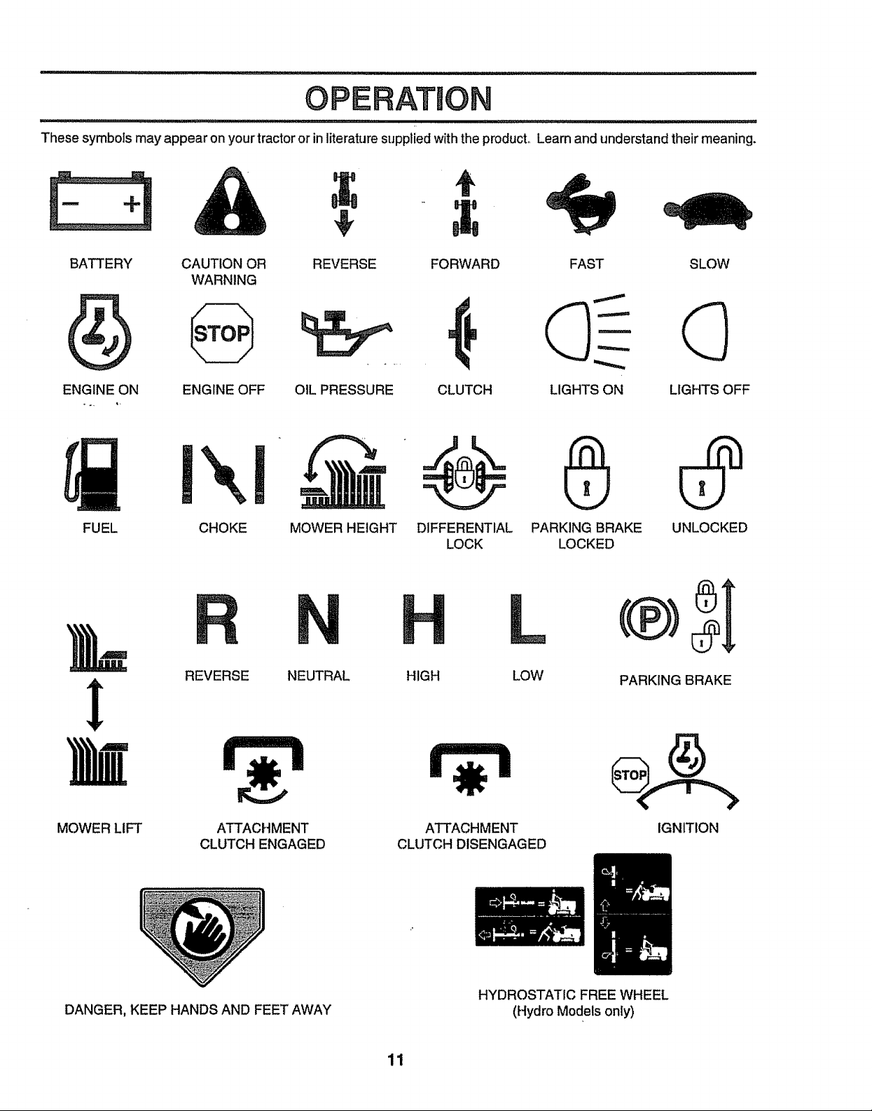
OPERATION
These symbols may appear on your tractor or in literature supplied with the producL Learn and understand their meaning.
BATTERY
CAUTION OR REVERSE FORWARD FAST SLOW
WARNING
....
ENGINE ON
FUEL CHOKE MOWER HEIGHT DIFFERENTIAL PARKING BRAKE UNLOCKED
ENGINE OFF OIL PRESSURE CLUTCH LIGHTS ON LIGHTS OFF
LOCK LOCKED
REVERSE NEUTRAL HIGH
MOWER LIFT
DANGER, KEEP HANDS AND FEET AWAY
ATTACHMENT
CLUTCH ENGAGED
ATTACHMENT
CLUTCH DISENGAGED
HYDROSTATIC FREE WHEEL
11
LOW PARKING BRAKE
IGNITION
(Hydro Models only)
OPERATION
............................... lU lUlll
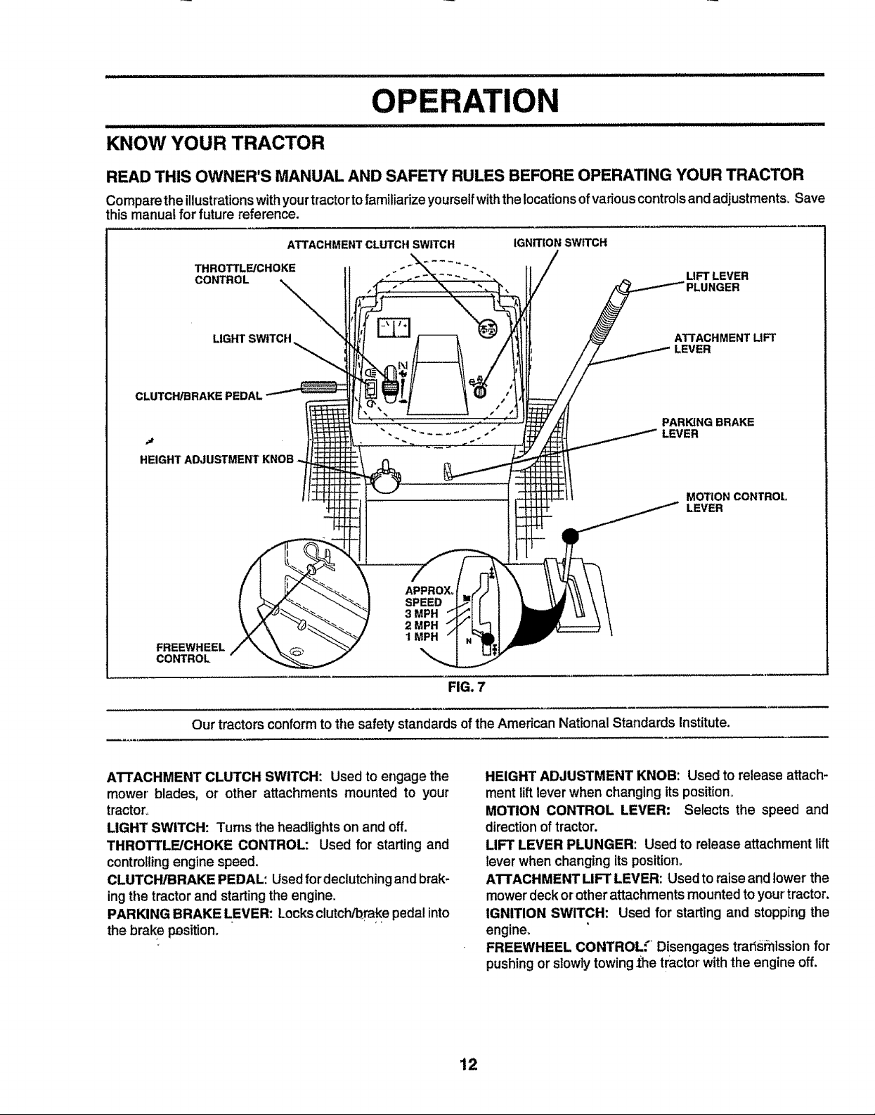
KNOW YOUR TRACTOR
READ THIS OWNER'S MANUAL AND SAFETY RULES BEFORE OPERATING YOUR TRACTOR
Comparethe illustrationswithyourtractortofamiliarizeyourselfwiththe locationsofvadous controlsand adjustments. Save
this manual for future reference.
THROTTLE/CHOKE
CONTROL
LIGHT SWITCH
CLUTCH/BRAKE PEDAL
.,a
HEIGHT ADJUSTMENT
FREEWHEEL
CONTROL
ATTACHMENT CLUTCH SWITCH
APPROX,
SPEED
3 MPH
2 MPH
1 MPH
IGNITION SWITCH
LIFT LEVER
ATTACHMENT LIFT
LEVER
PARING BRAKE
LEVER
MOTION CONTROL
LEVER
Our tractors conformto the safety standards of the American National Standards Institute.
ATTACHMENT CLUTCH SWITCH: Used to engage the
mower blades, or other attachments mounted to your
tractor°
LIGHT SWITCH: Turns the headlights on and off.
THROTTLE/CHOKE CONTROL: Used for starting and
controllingengine speed,
CLUTCH/BRAKE PEDAL: Usedfordeclutching and brak-
ingthe tractorand starting the engine.
PARKING BRAKE LEVER: Locksclutch/brakepedal into
the brake p_sitiono
FIG. 7
HEIGHT ADJUSTMENT KNOB: Used to release attach-
ment lift lever when changing itsposition,
MOTION CONTROL LEVER: Selects the speed and
directionof tractor.
LIFT LEVER PLUNGER: Used to release attachment lift
lever when changing itsposition_
ATrACHMENT LIFT LEVER: Used to raiseand lower the
mower deck or other attachments mounted toyourtractor,
IGNITION SWITCH: Used for starting and stopping the
engine,
FREEWHEEL CONTROL'." Disengages trads_nlssionfor
pushing or slowly towing1he tractorwith the engine off.
12
OPERATION
i,i ll,lll i i ...................................................
The operation of any tractor can result in foreign objects thrown into the eyes, which can
result in severe eye damage. Always wear safety glasses oreye shields while operating your
tractor or performing any adjustments or repairs. We recommend a wide vision safety mask
over the spectacles or standard safety glasses.
HOW TO USE YOUR TRACTOR
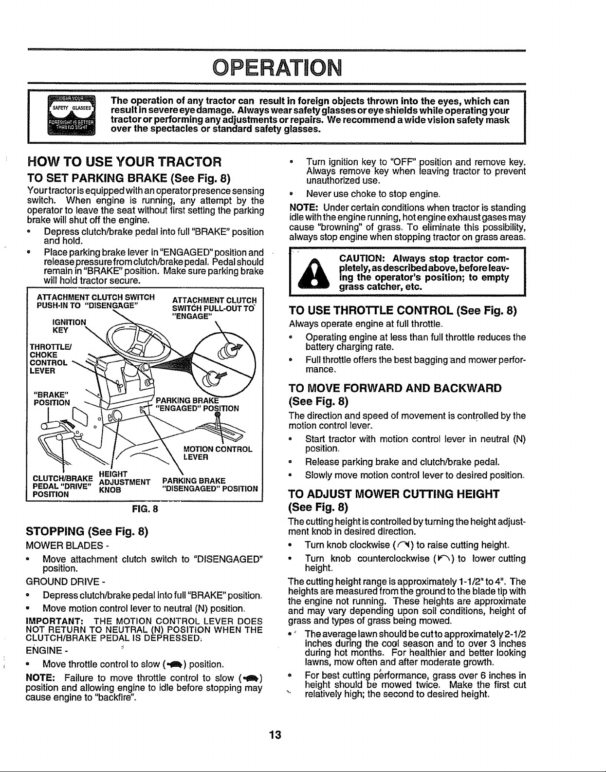
TO SET PARKING BRAKE (See Fig. 8)
Yourtractor isequipped withan operatorpresence sensing
switch. When engine is running, any attempt by the
operatorto leave the seat withoutfirstsetting the parking
brake will shut off the engine.
o Depress clutch/brake pedal into ful! "BRAKE" position
and hold.
• Place parking brake lever in"ENGAGED" position and
release pre,ssure from clutch/brake pedal Pedalshould
remain in' BRAKE" position. Makesure parking brake
will hold tractor secure.
ATTACHMENT CLUTCH SWITCH
PUSH*IN TO "DISENGAGE"
IGNITION
KEY "-_._
THROTTLE/
CHOKE
CONTROL *'_
LEVER
"BRAKE" "_"
POSITION \
CLUTCH/BRAKE ADJUSTMENT
PEDAL "DRIVE" KNOB
POSITION
HEIGHT
FIG. 8
STOPPING (See Fig. 8)
MOWER BLADES -
" Move attachment clutch switch to "D{SENGAGED"
position.
GROUND DRIVE -
• Depress clutch/brakepedal intofuII"BRAKE" position.
• Move motion control lever to neutral (N) position°
IMPORTANT: THE MOTION CONTROL LEVER DOES
NOT RETURN TO NEUTRAL (N) POSITION WHEN THE
CLUTCH/BRAKE PEDAL IS DEPRESSED;
ENGINE - :_
° Move throttlecontrol to slow (,_z_) position°
NOTE: Failure to move throttle control to slow (,gin.)
position and allowing engine to idle before stopping may
cause engine to "backfire".
ATTACHMENT CLUTCH
SWITC;H PULL-OUT TO"
"ENGAGE"
MOTION CONTROL
I.EVER
PARKING BRAKE
"DISENGAGED" POSITION
° Turn ignition key to "OFF" position and remove key.
Always remove key when leaving tractor to prevent
unauthorized user
• Never use choke to stop engine°
NOTE: Under certain conditions when tractor is standing
idle with the engine running, hot engine exhaust gases may
cause "browning" of grass° To eliminate this possibility,
always stop engine when stopping tractor on grass areas_
pletely, as described above, before leav-
CAUTION: Always stop tractor com-
,hoo. ra,o.'spoo.,on;,oorn. .
arass catcher etc,g , .
TO USE THROTTLE CONTROL (See Fig. 8)
Always operate engine at full throttler
° Operating engine at less than fuji throttle reduces the
battery charging rate.
° Fullthrottleoffersthe best baggingand mower perfor-
mance,
TO MOVE FORWARD AND BACKWARD
(See Fig. 8)
The directionand speed of movement is controlled bythe
motioncontrol lever.
° Start tractor with motion control lever in neutral (N)
position.
• Release parking brake and clutch/brake pedal,
° Slowly move motioncontrol lever to desired position°
TO ADJUST MOWER CUTTING HEIGHT
(See Fig. 8)
The cutting heightis controlled by turningthe height adjust-
ment knob in desired direction.
° Turn knob clockwise (F_I) to raise cutting height.
. Turn knob counterclockwise (v_)to lower cutting
height,,
The cutting height range isapproximately 1-1/2" to 4". The
heights are measured from the ground to the blade tip with
the engine not running. These heights are approximate
and may vary depending upon soil conditions, height of
grass and types of grass being mowed.
-" The average lawn should be cut to approximately 2-1/2
inches dunng the cool season and to over 3 inches
during hot months. For healthier and better looking
lawns, mow often and after moderate growth.
° For best cutting performance, grass over 6 inches in
height should be mowed twice° Make the first cut
_° relatively high; the second to desired height,
13
OPERATION
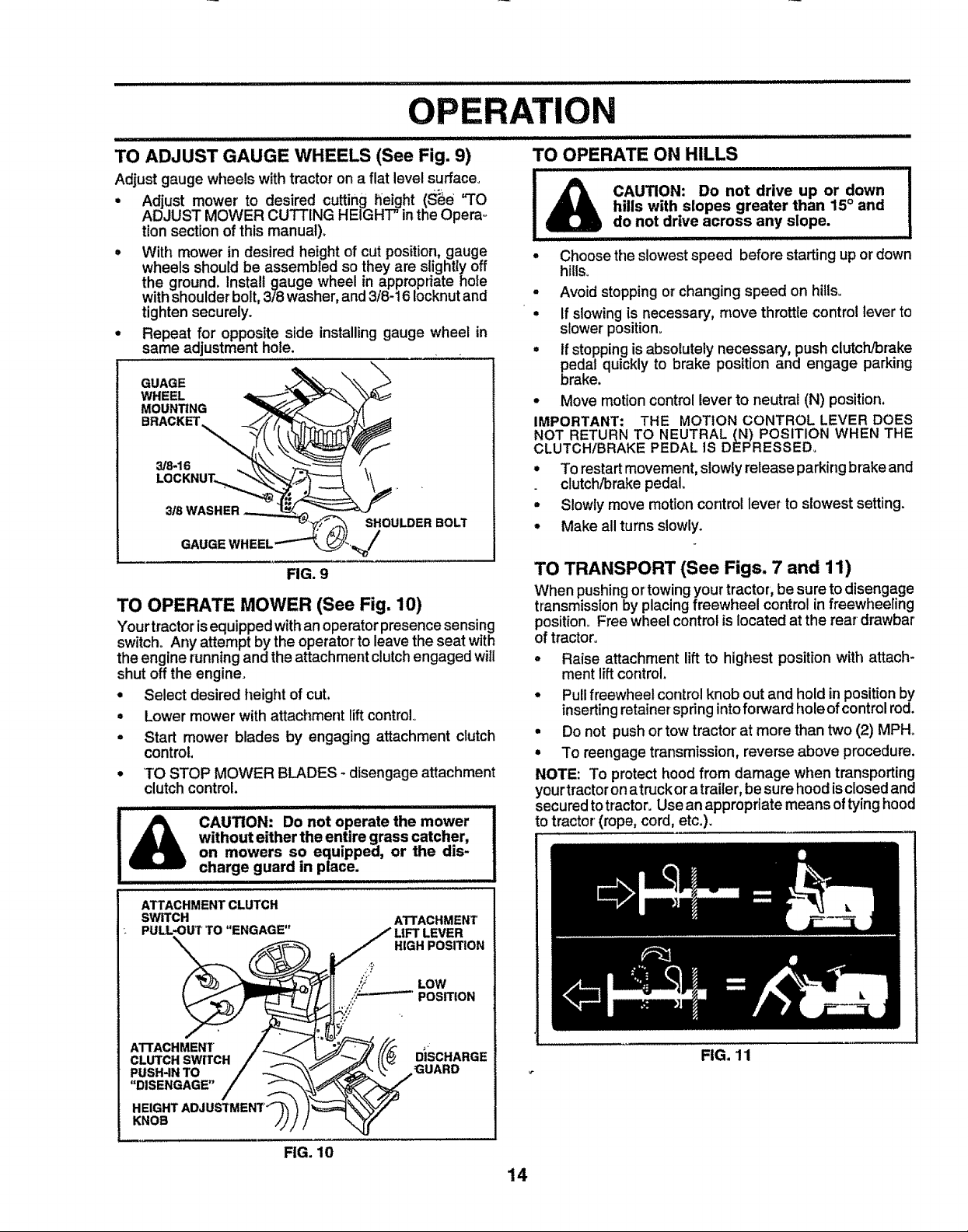
TO ADJUST GAUGE WHEELS (See Fig. 9)
Adjust gauge wheels with tractoron a flat level surface°
• Adjust mower to desired cutting height (s_e "TO
ADJUST MOWER CUTTING HEIGHT" inthe Opera-
tion sectionof this manuat)_
• With mower in desired height of cutposition, gauge
wheels should be assembled so they are siighttyoff
the ground. Install gauge wheel in appropriate hole
withshoulderbolt,3/8 washer, and3/8-16 Iocknutand
tighten securely.
• Repeat for opposite side installinggauge wheel in
same adjustment hole.
WHEEL
MOUNTING
GUAGE
3/8-16
SHOULDER BOLT
FIG. 9
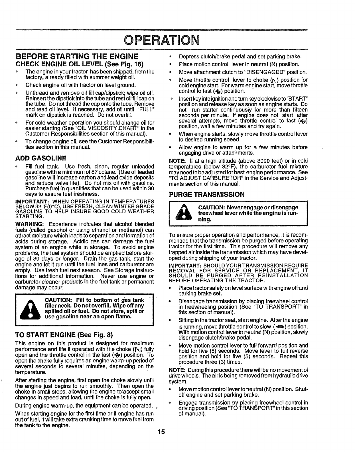
TO OPERATE MOWER (See Fig. 10)
Yourtractorisequipped withan operatorpresence sensing
switch° Any attempt by the operator to leavethe seat with
theengine running and theattachment clutchengaged will
shut off the engine.
, Select desired height ofcut.
° Lower mower with attachment liftcontrol
• Start mower blades by engaging attachment clutch
control
° TO STOP MOWER BLADES _disengageattachment
clutchcontrol.
................. ii llllllll illl
without either the entire grass catcher,
l_ CAUTION: Do not operate the mower
on mowers so equipped, or the dis-
charge guard in place.
TO OPERATE ON HILLS
J IIILIIII I
_l_ CAUTION: Do not drive up or down I
I _ hills with slopes greater than 15° and
! U do not drive across any S!ope.
• Choose the slowest speed before starting up or'down
hills.
° Avoid stopping or changing speed on hills.
° If slowing is necessary, move throttle control lever to
slower position,
• If stopping is absolutely necessary, push clutch/brake
pedal quickly to brake position and engage parking
brake.
° Move motion control lever to neutral (N) position,
IMPORTANT: THE MOTION CONTROL LEVER DOES
NOT RETURN TO NEUTRAL (N) POSITION WHEN THE
CLUTCH/BRAKE PEDAL lS DEPRESSED.
° To restartmovement, slowly release parkingbrakeand
clutch/brakepedal.
° Slowly move motioncontrollever to slowest setting.
* Make all turns slowly.
TO TRANSPORT (See Figs, 7 and 11)
When pushingortowingyour tractor, be sureto disengage
transmissionby placing freewheel control in freewheeling
position. Free wheel control is located at the rear drawbar
of tractor.
- Raise attachment liftto highest position with attach-
mentliftcontrol.
° Pullfreewheel control knob out and hold in positionby
insertingretainer spring intoforward hole ofcontrolrod.
• Do not pushor towtractor at more than two (2) MPH.
° To reengage transmission, reverse above procedure.
NOTE: To protect hood from damage wi_entransporting
yourtractoronatruck ora trailer,be surehood isclosedand
securedto tractor. Use an appropriate means oftying hood
to tractor'(rope, cord, etc.).
!
ATTACHMENT CLUTCH
SWITCH
PULL_}UT TO "ENGAGE"
ATTACHMENT _SCHARGE
CLUTCH SWITCH
PUSH4N TO GUARD
"DISENGAGE"
HEIGHTAI
KNOB
ATTACHMENT
LIFT LEVER
HIGH POSITION
FIG. 10
FIG. 11
14
O
A ON
BEFORE STARTING THE ENGINE
CHECK ENGINE OIL LEVEL (See Fig. 16)
= The engine inyourtractor has been shipped,fromthe
factory, already filled withsummer weight oil,
° Check engine oil with tractor on level ground+
° Unthread and remove oil fill cap/dipstick;wipe oi!off+
Reinsertthe dipstickintothetubeand restoilfillcapon
thetube° Do notthread the capontothetube. Remove
and read oi! level, if necessary, add oil until "FULL"
mark on dipstickis reached. Do not overfill
= For cold weather operation you shouldchange oil for
easier starting (See OIL VISCOSITY' CHART' inthe
Customer Responsibilitiessection of this manual)+
- To change engine oil, see the Customer Responsibili-
ties section inthis manual+
ADD GASOLINE
. Fill fuel tank. Use fresh, clean, regular unleaded
gasoline with a minimum of 87 octane+ (Use of leaded
gasoline will increase carbon and _ead oxide deposits
and reduce valve life). Do not mix oil with gasoline.
Purchase fuel in quantities that can be used within 30
days to assure fuel freshness.
IMPORTANT: WHEN OPERATING tN TEMPERATURES
BELOW 32OF(0oC),USE FRESH, CLEANWINTER GRADE
GASOLINE TO HELP INSURE GOOD COLD WEATHER
STARTING.
WARNING: Experience indicates that alcohol blended
fuels (called gasohot or using ethanol or methanoD can
attract moisture which leads to separation and formation of
acids during storage. Acidic gas can damage the fuel
system of an engine while in storage. +Toavoid engine
problems, the fuel system should be emptied before stor+
age of 30 days or longer. Drain the gas tank, start the
engine and let it run until the fuel lines and carburetor are
empty. Use fresh fuel next season. See Storage Instruc-
tions for additional information° Never use engine or
carburetor cleaner products in the fuel tank or permanent
damage may occur.
filler neck. Do not overfill. Wipe offany
i_ CAUTION: Fill to bottom of gas tank +
TO START ENGINE (See Fig. 8)
This engine on this product is designed for maximum
performance and life if operated with the choke (l\I) fully
open and the throttle control in the fast ('Pe_)position, To
open the choke fully requires an engine warm-up period of
several seconds to several minutes, depending on the
temperature+
After starting the engine; first open the choke slowly until
the engine just begins to run smoothly,. Then open the
choke in small steps, allowing the engine to_ccept small
changes in speed and load, until the choke is fully open.
During engine warm-up, the equipment can be operated.
When starting engine for the first time or if engine has run
out of fuel, it will take extra cranking time to move fuel from
the tank to the engine.
spilled oil or fuel. Do not store, spill or
use gasoline near an open flame.
• Depress clutch/brake pedal and set parking brake.
o Place motion control lever in neutral (N) position.
o Move attachment ctutch to "DISENGAGED" position+
= Move throttle control lever to choke (N) position for
cold engine start+ For warm engine start, move throttle
control to fast (,_) position.
° Insertkeyinto ignitionand turn keyclockwise to"START"
position and release key as soon as engine starts. Do
not run starter continuously for more than fifteen
seconds per minute. If engine does not start after
several attempts, move throttle control to fast (=_)
position, wait a few minutes and try again.
° When engine starts, slowly move throttle control lever
to desired running speed°
° Allow engine to warm up for a few minutes before
engaging drive or attachments.
NOTE: If at a high altitude (above 3000 feet) or in cold
temperatures (below 32°F), the carburetor fuel mixture
may needto be adjusted forbest engine performance. See
"TO ADJUST CARBURETOR" inthe Service and Adjust-
ments section of this manual
PURGE TRANSMISSION
' i i,_ ,, _,, _1,,11,1ii1_,,,
CAUTION: Never engage or disengage
freewheel lever while the engine is run-
ning.
To ensure proper operation and performance, itis recom-
mended thatthe transmissionbe purged before operating
tractorfor the first time. This procedure will remove any
trapped air insidethe transmissionwhichmay have devel-
oped duringshipping of your tractor+
IMPORTANT: SHOULD YOURTRANSMISSION REQUIRE
REMOVAL FOR SERVICE OR REPLACEMENT, IT
SHOULD BE PURGED AFTER REINSTALLATtON
BEFORE OPERATING THE TRACTOR.
° Placetractorsafely on level surface withengine offand
parkingbrake set.
° Disengage transmission by placing freewheel control
in freewheeling position (See "TO TRANSPORT" in
this section of manual)+
- Sittinginthetractorseat, start engine. After theengine
isrunning,movethrottlecontroltoslow (.€_) position.
With motioncontrollever in neutral (N) position,slowly
disengage clutctVbrakepedal.
- Move motioncontrollever to full forward position and
hold for five (5) seconds. Move lever to full reverse
positionand hold for five (5) seconds+ Repeat this
procedurethree (3) times.
NOTE: Duringthisprocedurethere will be no movement of
drivewheels. The air isbeing removedfrom hydraulic drive
system_
- Move motion controlleverto neutral(N) position. Shut-
off engine and set parking brake,+
. Engage transmission by placing freewheel controlin
driving position(See q'OTRANSPORT' inthissection
of manual).
15
ATION
° Sitting inthetractor seat, start engine. Afterthe engine
is running, move throttle control to half (1!2) speed.
With motion control lever'in neutral (N) position, slowly
disengage clutch/brake pedal.
° Slowly move motior_ control lever forward, after the
tractor moves approximately five (5) feet, slowly move
motion control lever to reverse position. After the
tractor moves approximately five (5) feet return the
motion control lever to the neutral (N) position. Repeat
this procedure with the motion control lever three (3)
times.
° Your' tractor is now purged and now ready for normal
operation.
MOWING TIPS
° "firechains cannot be used when the mower housing
is attached to tractor.
- Mower should be properly leveled for best mowing
performance. See "TO LEVEL MOWER HOUSING in
the Service and Adjustments section of this manual.
• The left hand side of mower should be used for tdm-
mingo
° Drive so that clippings are discharged onto the area
that has been cut. Have the cut area to the right ofthe
machine. This will result in a more even distdbution of
clippingsand more uniformcutting.
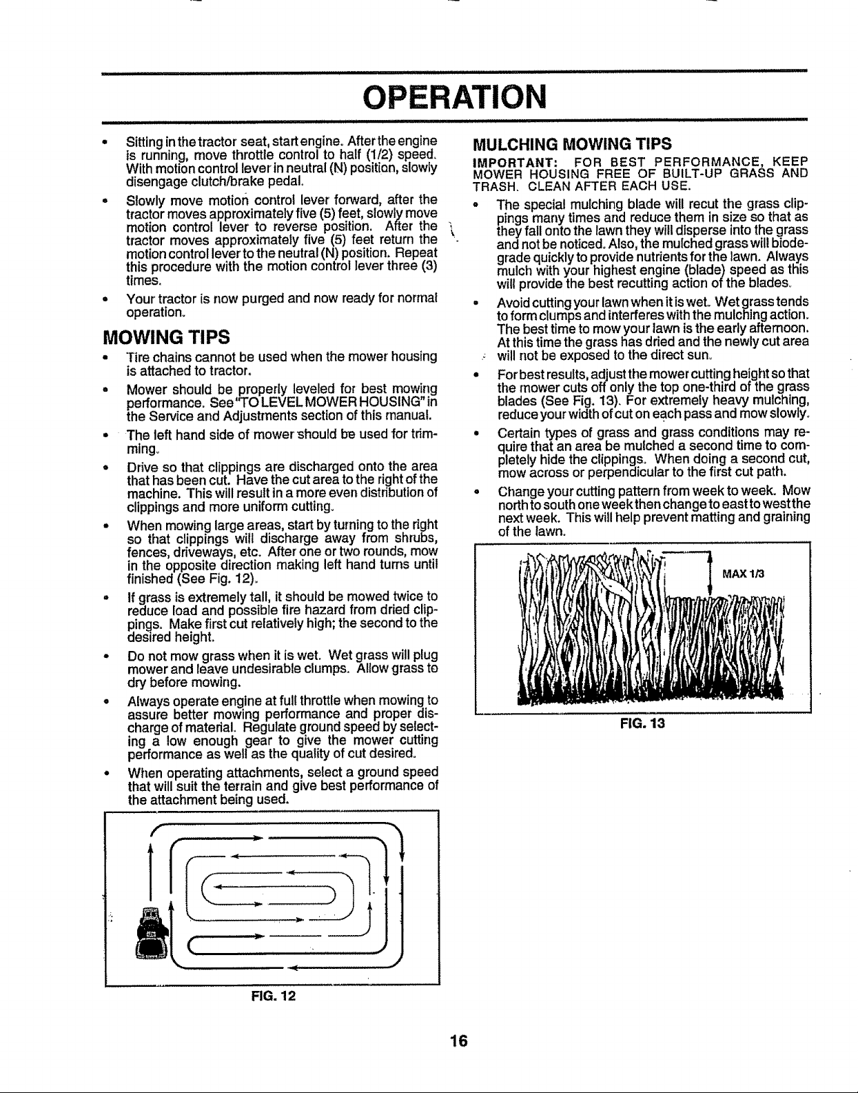
° When mowing large areas, start by turning to the dght
so that clippings will discharge away from shrubs,
fences, driveways etc. After one or two rounds, mow
in the opposite direction making left hand turns until
finished (See Fig. t2).
° If grass is extremely tall, it should be mowed twice to
reduce load and possible fire hazard from dried clip-
pings° Make first cut relatively high; the second to the
desired height.
° Do not mow grass when it is wet. Wet grass will plug
mower and leave undesirable clumps. Allow grass to
dry before mowing.
° Always operate engine at full throttle when mowing to
assure better mowing performance and proper dis-
charge of matedal. Regulate ground speed by select-
ing a low enough gear to give the mower cutting
performance as welt as the quality of cutdesired°
• When operating attachments, select a ground speed
that will suit the terrain and give best performance of
the attachment being used.
MULCHING MOWING TIPS
IMPORTANT: FOR BEST PERFORMANCE, KEEP
MOWER HOUSING FREE OF BUILT-UP GRASS AND
TRASH, CLEAN AFTER EACH USE.
° The special mulching blade will recut the grass clip-
pings many times and reduce them in size so that as
theyfail onto the lawnthey willdisperse intothe grass
and not be noticed. Also, the mulchedgrass wiltbiode-
grade quickly to provide nutrients for the lawn. Always
mulch with your highest engine (blade) speed as this
willprovide the best recutting action of the blades_
• Avoid cutting your lawn when it is wet. Wet grass tends
to form clumps and interfereswith the mulching action.
The best time to mow your lawn is the early afternoon.
At this time the grass has dried and the newly cut area
will not be exposed to the direct sun_
= For best results, adjust the mower cutting height so that
the mower cuts offonly the top one-third of the grass
blades (See Fig. 13). For extremely heavy mulching,
reduce your width of cut on each pass and mow slowly.
° Certain types of grass and grass conditions may re-
quire that an area be mulched a second time to com-
pletely hide the clippings. When doing a second cut,
mow across or perpendicular to the first cut path.
o Change your cutting pattern from week to week. Mow
north to south one week then change to east to west the
next week. This will t_elpprevent matting and graining
of the lawn.
MAX 1/3
FIG. 13
f
FIG. 12
16
CUSTOMER
LITIES
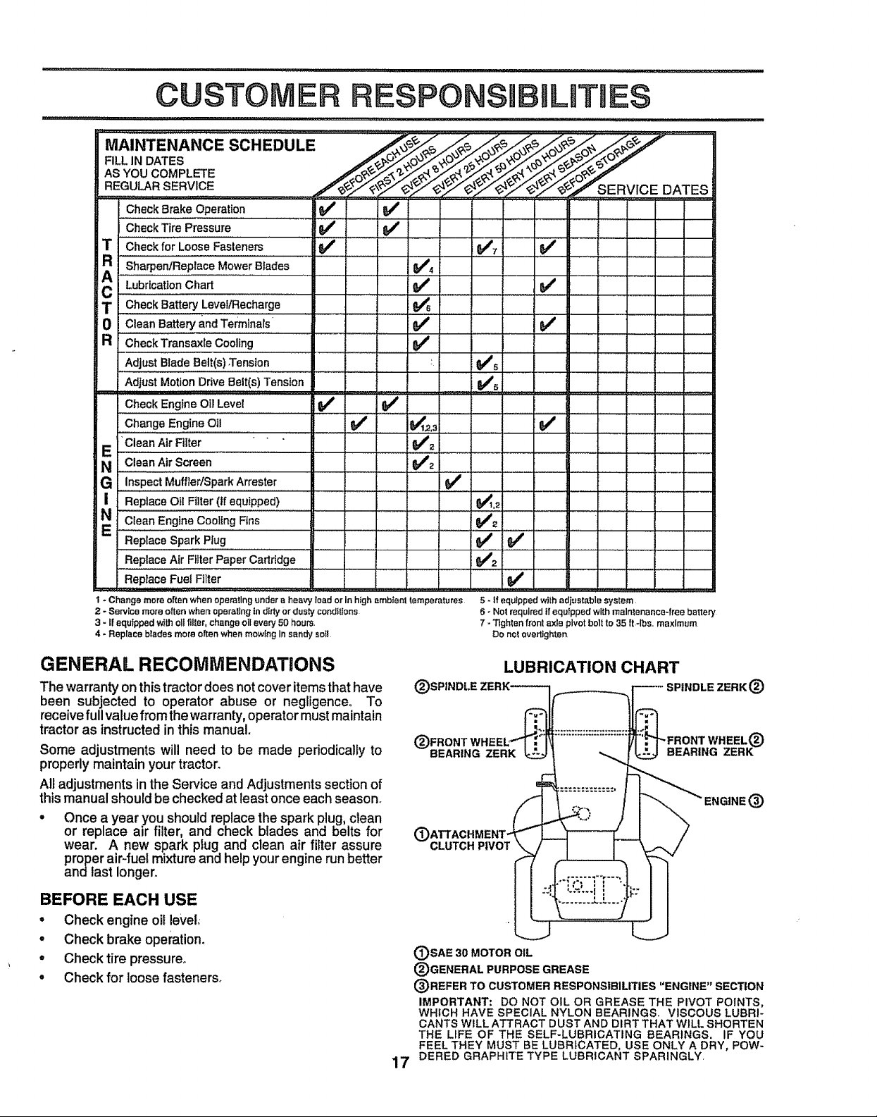
MA'.TE.A.CESCHEoULE ................ ..................
AS YOU COMPLETE
REGULAR SERVICE /_O-_=c_,,,r',=,
CheckBrakeOperation ::_ ...................V€' ...............
CheckTirePressure _
CheckforLooseFasteners !_ _€#" "_ " i =
AR SharpenlReplace Mower Btades ............... $/4
C Lobr_cattonC"art V' , , ,V". .
T CheckBatteryLeveVRecharge ...... .... _ _ ! " ............
0 C,eanBa.eryandTe ,nars ...............V'
R CheckTransaxleCoollng _€_ " :
Adjust BladeBelt(s).Tension : _'_ ...........................
AdjustMotionDriveBelt(s)Tension Ks
CheckEngineOilLevel !!{b/ _,/
ChangeEngineOil _ 0€_'12.3 _€'
E Clean Air Filter , , Q##'_........
N CleanAir Screen _'°2
G InspectMuffler/SparkArrester
I Replace Oil Filter(if equipped) @€_1._
_/_.,_- _,_e- SERV.ICE DATES
,= ...................... : : -
NE CleanEngineCoo,ingFins . i........... _q_i2
ReplaceSparkPlug _
Replace Air FilterPaper Cartridge i{_#'2
ReplaceFuelFilter Vj'
1 - Change more often when operetlng under a heavy load or tn high ,_mbtenl lemperatures
2 -Servtcemore often when operallng in dirtyor dus{y condtt{ons
3 - t! equipped with otl fil_er,change oHevery 50 hours
4 - Replace brades more often when mowing Insandy sot!
GENERAL RECOMMENDATIONS
The warranty on thistractor does not cover items that have
been subjected to operator abuse or negligence° To
receive full value from the warranty, operator must maintain
tractor as instructedin this manual.
Some adjustments will need to be made periodically to
properly maintain your tractor_
All adjustments in the Service and Adjustments section of
this manual should be checked at least once each season_
Once a year you should replace the spark plug, clean
or replace air filter, and check blades and belts for
wear. A new spark plug and clean air filter assure
proper air-fuel mixture and help your engine run better
andlast longer.
BEFORE EACH USE
• Check engine oHlevel.
° Check brake operation.
, Check tire pressure.
, Check for loosefasteners°
5 - If equipped with adtestable system
6 _No! requited if equipped with maintenance-free battery
7 - Tighten front axle pivot bolt to 35 R-lbe,, maximum
Do not overlighten
LUBRICATION CHART
_- SPINDLE ZERK ®
(3_!ATTACHMENT_
'% ENGINE (_
L:-:..i !
CLUTCH PlVOi _
(_)SAE 30 MOTOR OIL
®GENERAL PURPOSE GREASE
(_)REFER TO CUSTOMER RESPONSIBILITIES "ENGINE" SECTION
IMPORTANT: DO NOT OIL OR GREASE THE PIVOT POINTS,
WHICH HAVE SPECIAL NYLON BEARINGS, VISCOUS LUBRI-
CANTS WILL ATTRACT DUST AND DIRT THAT WILL SHORTEN
THE LIFE OF THE SELF-LUBRICATING BEARINGS. IF YOU
FEEL THEY MUST BE LUBRICATED, USE ONLY A DRY, POW-
...... .L.L..'
7
17 DERED GRAPHITE TYPE LUBRICANT SPARINGLY,
ER R
TRACTOR
Always observe safety rules when performingany mainte-
nanceo
BRAKE OPERATION
If tractor requires more than six (6) feet stoppingdistance
at high speed in highest gear, thenbrake must be adjusted°
(See "TO ADJUST BRAKE" in the Service and Adjust-
ments section of this manual)_
TIRES
• Maintain proper air pressure in all tires (See "PROD-
UCT SPECIFICATIONS" on page 3 of this manual).
• Keep tires free of gasoline, oil, or insect control chemi-
cals which can harm rubber°
• Avoid stumps, stones, deep ruts, sharp objects and
other hazards that may cause tire damage_
BLADE CARE
For best results mower blades must be kept sharp. Re-
place bent or damaged blades.
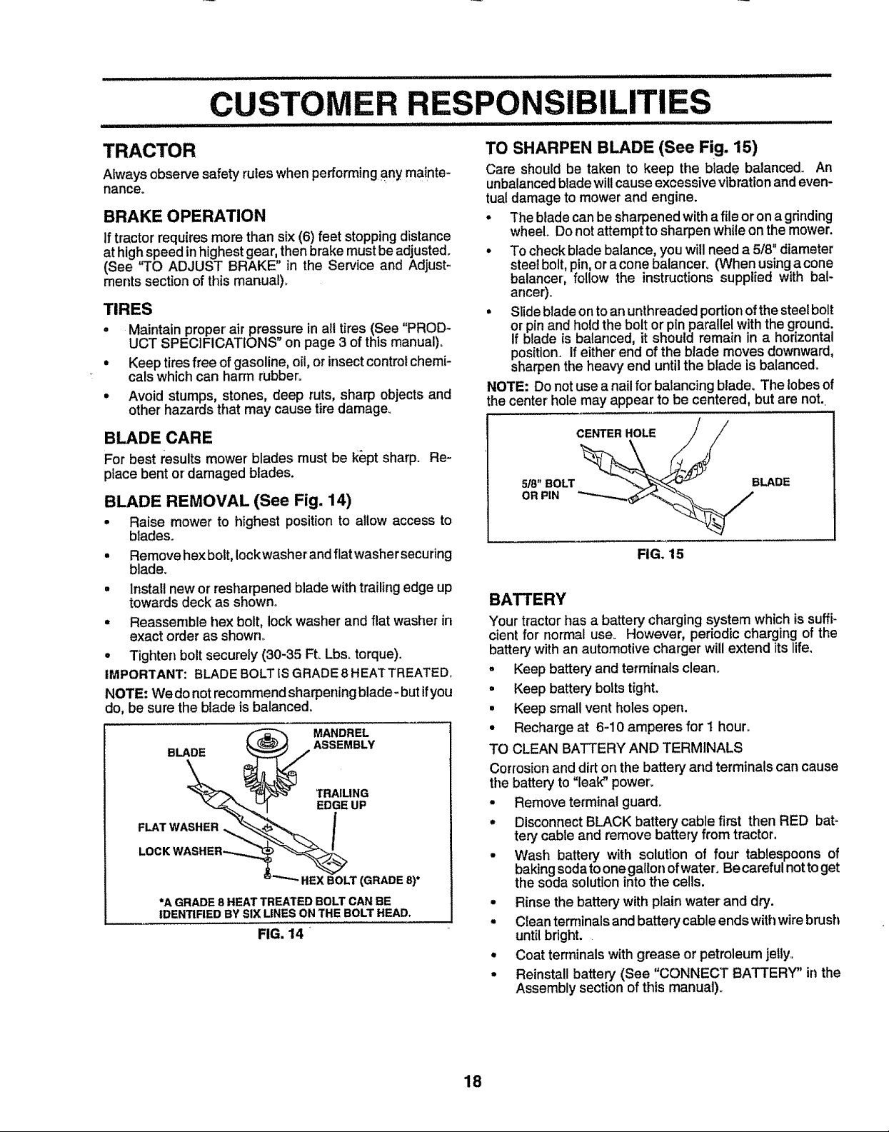
BLADE REMOVAL (See Fig. 14)
• Raise mower to highest positionto allow access to
blades.
• Remove hex bolt, lock washer andflat'washer securing
blade.
• Install new or resharpened blade with trailing edge up
towards deck as shown.
• Reassemble hex bolt, lock washer and flat washer in
exact order as shown_
• Tighten bolt securely (30-35 Ft. Lbs. torque).
IMPORTANT: BLADE BOLT ISGRADE8 HEATTREATED_
NOTE: We donotrecommend sharpening blade- but ifyou
do, be sure the blade is balanced.
BLADE ASSEMBLY
_ MANDREL
EDGE UP
i_ TRAILING
LOCK WASHER,_,.,,._
FLAT W _LT
(GRADE 8)*
*A GRADE 8 HEAT TREATED BOLT CAN BE
IDENTIRED BY SIX LINES ON THE BOLT HEAD,
FIG. 14 •
TO SHARPEN BLADE (See Fig. 15)
Care should be taken to keep the blade balanced_ An
unbalanced bladewillcause excessivevibrationandeven-
tualdamage to mower and engine.
• The blade can be sharpenedwith a file or ona grinding
wheel Do notattemptto sharpen while on the mower.
ancer).
• Slide blade on toan unthreaded portion ofthe steel bolt
or pin and hold the bolt or pin parallel with the ground.
if blade is balanced, it should remain in a horizontal
position, if either end of the blade moves downward,
sharpen the heavy end until the blade is balanced.
NOTE: Do not use a nail for balancing blade. The lobes of
he center hole may appear to be centered, but are not.
CENTER HOLE
5/8" BOLT
OR PIN
BLADE
FIG. 15
BATTERY
Your tractor has a battery charging system which is suffi-
cient for normal use. However, periodic charging of the
battery with an automotive charger will extend its life,
° Keep battery and terminals clean_
- Keep battery bolts tight.
• Keep small vent holes open.
• Recharge at 6-10 amperes for 1 hour.
TO CLEAN BATTERY AND TERMINALS
Corrosion and dirt on the battery and terminals carl cause
the battery to "leak" power.
° Remove terminal guard.
° Disconnect BLACK battery cable first then RED bat-
tery cable and remove battery from tractor.
• Wash battery with solution of four tablespoons of
baking soda toone gallon ofwater, Be careful notto get
the soda solution intothe cells.
• Rinse the battery with plain water and dry.
° Clean temfinals and battery cable ends with wire brush
until bright.
• Coat terminals with grease or petroleum jelly.
° Reinstall battery (See "CONNECT BATTERY" in the
Assembly section of this manual).
18
 Loading...