

Page 1

CRflFTSMRN
MODEL NUMBER 917.256544 owner’s manual
• Assembly
• Operation
• Customer Responsibilities
• Service and Adjustments
• Repair Parts
Thiit product has emission anqine which operates difisrenUy
from previously ouilt enginec. Before you start the engine, read
and urderstand this Owner s Manuai.
CAUTION: Read and follow all safety rules and instructions before operating this equipment.
FOR CONSUMER ASSISTANCE HOT LINE, CALL THIS TOLL FREE NUMBER: 1 -800-659-5917
Sears. Roebuck and Co., Hoffman Estates, IL 60179 U.S.A.
Page 2

SAFETY RULES
A
IMPORTANT: THIS CUTTING MACHINE IS CAPABLE OF AMPUTATING HANDS AND FEET AND THROWING OBJECTS.
FAILURE TO OBSERVE THE FOLLOWING SAFETY INSTRUCTIONS COULD RESULT IN SERIOUS INJURY OR DEATH.
I. GENERAL OPERATION
Read, understand, and follow all instructions in the manual
and on the machine before starting.
Only allow responsible adults, who are familiar with the
Instnjctlons, to operate the machine.
Clear the area of objects such as rocks, toys, wire, etc.,
which could be picked up and thrown by the blade.
Be sure the area is clear of other people before mowing. Stop
machine if anyone enters the area.
Never carry passengers.
Do not mow in reverse unless absolutely necessary. Always
look down and behind before and while backing.
Be aware of the mower discharge direction and do not point
it at anyone. Do not operate the mower without either the
entire grass catcher or the guard in place.
Slow down before turning.
Never leave a running machine unattended. Always turn off
blades, set parking brake, stop engine, and remove keys
before dismounting.
Turn off blades when not mowing.
Stop engine before removing grass catcher or unclogging
chute.
Mow only in daylight or good artificial light.
Do not operate the machine while under the influence of
alcohol or drugs.
Watch for traffic when operating near or crossing roadways.
Use extra care when loading or unloading the machine into
a trailer or truck.
II. SLOPE OPERATION
Slopes are a major factor related to loss-of-control and
tipover accidents, which can result in severe injury or
death. All slopes require extra caution. If you cannot back
up the slope or if you feel uneasy on it, do not mow it.
DO:
Mow up and down slopes, not across.
Remove obstacles such as rocks, tree limbs, etc.
Watch for holes, ruts, or bumps. Uneven terrain could
overturn the machine. Tall grass can hide obstacles.
Use slow speed. Choose a low gear so that you will not have
to stop or shift while on the slope.
Follow the manufacturer’s recommendations for wheel
weights or counterweights to improve stability.
Use extra care with grass catchers or other attachments.
These can change the stability of the machine.
Keep all movement on the slopes stow and gradual. Do not
make sudden changes in speed or direction.
Avoid starting or slopping on a slope. If tires lose traction,
disengage the blades and proceed slowly straight 6awn the
slope.
DO NOT:
• Do not turn on slopes unless necessary, and then, turn slowly
and gradually downhill, if possible.
• Do not mow near drop-offs, ditches, or embankments. The
mower could suddenly turn over if a wheel is over the edge
of a cliff or ditch, or if an edge caves in.
• Do not mow on wet grass. Reduced traction could cause
sliding,
• Do not try to stabilize the machine by putting your foot on the
ground.
• Do not use grass catcher on steep slopes.
........................................................ .......................
Safe Operation Practices for Ride-On Mowers
III. CHILDREN
Tragic accidents can occur if the operator is not alert to the
presence of children. Children are often attracted to the
machine and the mowing activity. Never assume that
children will remain where you last saw them.
Keep children out of the mowing area and underthe watchful
care of another responsible adult.
Be alert and turn machine off if children enter the area.
Before and when backing, look behind and down for small
children.
Never carry children. They may fall off and be seriously
injured or inferfere with safe machine operation.
Never allow children to operate the machine.
Use extra care when approaching blind corners, shrubs,
trees, or other objects that may obscure vision.
IV. SERVICE
• Use extra care in handling gasoline and other fuels. They are
flammable and vapors are explosive.
- Use only an approved container.
- Never remove gas cap or add fuel with the engine
running. Allow engine to cool before refueling. Do not
smoke.
- Never refuel the machine indoors.
- Never store the machine or fuel container inside where
there is an open flame, such as a water heater.
• Never run a machine inside a closed area.
• Keep nuts and bolts, especially blade attachment bolls, tight
and keep equipment in good condition,
• Never tamper with safely devices. Check their proper
operation regularly.
• Keep machine free of grass, leaves, or other debris build-up.
Clean oil or fuel spillage. Allow machine to cool before
storing.
• Stop and inspect the equipment if you strike an object.
Repair, if necessary, before restarting.
• Never make adjustments or repairs with the engine running.
• Qrasscatchercomponents are subject to wear, damage, and
deterioration, which could expose moving parts or allow
objects to be thrown. Frequently check components and
replace with manufacturer's recommended parts, when nec
essary.
• Mower blades are sharp and can cut. Wrap the blade(s) or
wear gloves, and use extra caution when servicing them,
• Check brake operation frequently. Adjust and service as
required.
Lookfor this symbol to point out important
safety precautions. It means
A
A
CAUTION!!! BECOME ALERT!!1 YOUR
SAFETY IS INVOLVED.
CAUTION: Always disconnect spark plug
wire and place wire where it cannot contact
spark plug in order to prevent accidental
starting when setting up, transporting,
adjusting or making repairs.
A WARNING A
The engine exhaust from this product contains
chemicais known to the State of Caiifornia to
cause cancer, birth defects, or other reproduc
tive harm.
A
Page 3

CONGRATULATIONS on your purchase of a Sears
Tractor, it has been designed, engineered and manufac
tured to give you the best possibie dependability and
performance.
Should you experience any problem you cannot easily
remedy, please contact your nearest Sears Authorized
Service Center/Department. We have competent, welltrained technicians and the proper tools to service or repair
this tractor.
Please read and retain this manuai. The instructions will
enable you to assemble and maintain your tractor properly.
Always observe the “SAFETY RULES”.
MODEL
NUMBER
917.256544
SERIAL
NUMBER
DATEOFPURCH.ASE
THEMODELANDSERIAL NUMBERS WILL BE FOUND
ON A PLATE UNDER THE SEAT,
YOU SHOULD RECORD BOTH SERIAL NUMBER AND
DATE OF PURCHASE AND KEEP IN A SAFE PLACE
FOR FUTURE REFERENCE.
MAINTENANCE AGREEMENT
A Sears Maintenance Agreement is available on this prod
uct. Contact your nearest Sears store for details.
CUSTOMER RESPONSiBlLiTIES
» Read and observe the safety rules.
® Foliowa regularschedule in maintaining, caringforand
using your tractor.
® Follow the instructions under “Customer Responsibili
ties” and “Storage” sections of this owner’s manual.
PRODUCT SPECIFICATIONS
HORSEPOWER; 15.0
GASOLINE CAPACITY
AND TYPE:
OIL TYPE (APl-SF/SG): SAE 10W30 (above 32“F)
OIL CAPACITY:
SPARK PLUG:
(GAP: .040")
VALVE CLEARANCE; NOT ADJUSTABLE
GROUND SPEED (MPH); FORWARD;
TIRE PRESSURE; FRONT: 14 PS!
CHARGING SYSTEM; 3 AMPS BATTERY
BATTERY;
BLADE BOLT TORQUE; 30-35 FT. LBS.
WARNING: This tractor is equipped with an internal
combustion engine and should not be used on or near any
unimproved forest-covered, brush-covered or grass-cov
ered land unless the engine’s exhaust system is equipped
with a spark arrester meeting applicable local or state laws
(if any), if a spark arrester is used, it should be maintained
in effective working order by the operator.
In the state of California the above is required by law
(Section 4442 of the California Public Resources Code).
Other states may have similar laws. Federal laws apply on
federal lands. A spark arrester for the muffler is available
through your nearest Sears Authorized Service Center/
Department (See REPAIR PARTS section of this manual).
1.25 GALLONS
UNLEADED REGULAR
SAE 5W-30 (below 32“F]
W; FILTER: 4.0 PINTS
W/O FILTER: 3.5 PINTS
CHAMPION RC12YC
1st 1.1
2nd 1.5
3rd 2.3
4th 3.5
5th 4.4
6th 5.7
REVERSE: 1.7
REAR: 10PSi
5 AMPS HEADLIGHTS
AMP/HR: 30
MIN. CCA: 240
CASE SIZE: U1R
LIMITED TWO YEAR WARRANTY ON CRAFTSMAN RIDING EQUIPMENT
For two (2) years from the date of purchase, if this Craftsman Riding Equipment is maintained, lubricated and tuned up according to
the instructions in the owner's manual, Sears will repair or replace, free of charge, any parts found to be defective in material or
workmanship.
This Warranty does not cover:
» Expendable items which become worn during normal use, such as blades, spark plugs, air cleaners, belts, etc.
® Tire replacement or repair caused by punctures from outside objects, such as nails, thorns, stumps, or glass.
» Ftepairs necessary because of operator abuse, negligence, improper storage or accident or the failure to maintain the
equipment according to the instructions contained in the owner’s manual.
• Riding equipment used for commercial or rental purposes.
LIMITED 90 DAY WARRANTY ON BATTERY
For ninety (90) days from date of purchase, if any battery included with this riding equipment proves defective in material or
workmanship and our testing determines the battery will not hold a charge, Sears will replace the battery at no charge.
IN-HOME WARRANTY SERVICE ON YOUR CRAFTSMAN RIDING EQUIPMENT IS AVAILABLE AT NO-CHARGE FOR 30 DAYS
FROM THE DATE OF PURCHASE. PLEASE CONTACT YOUR NEAREST SERVICE CENTER. AFTER 30 DAYS FROM THE
DATE OF PURCHASE, WARRANTY SERVICE IS AVAILABLE BY TAKING YOUR CRAFTSMAN RIDING EQUIPMENT TO YOUR
NEAREST SEARS SERVICE CENTER. (IN-HOME WARRANTY SERVICE WILL STILL BE AVAILABLE AFTER 30 DAYS FROM
THE DATE OF PURCHASE BUT A STANDARD TRIP CHARGE WILL APPLY.) THIS WARRANTY APPLIES ONLY WHILE THIS
PRODUCT IS IN THE UNITED STATES.
This Warranty gives you specific legal rights, and you may also, have other rights which may vary from state to stale.
SEARS, ROEBUCK AND CO.. D/817 WA, HOFFMAN ESTATES, IL 60179
Page 4

TABLE OF CONTENTS
SAFETY RULES
PRODUCT SPECIFiCATIONS
CUSTOMER RESPONSIBIUTIES
...
.........................................................
........................................
.................. 3,15-19
2
WARRANTY .................................................................... 3
TABLE OF CONTENTS.
............................................. .....4
ASSEMBLY ......................................................... 7-9
OPERATION.......................................................... 10-14
INDEX
A
Accessories........................................ 5
Adjustments:
Brake
.......................................
Carburetor................................ 25
Mower: ’
Front-To-Back
Side-To-Side
Throttle Control Cable
Air Filter, Engine................................18
Air Screen, Engine ........... 18
Assembly..........
....................
........................
...............
.............................
22
21
7-9
B
Battery:
Charging
Cleaning
Starting with Weak Battery
Storage..................................... 26
Terminals
Belts:
Motion Drive
Mower Blade Drive
Blade:
Sharpening
Replacement............................ 16
Brake Adjustment
......................................
.................................
...................................
Removal/Replacement....... 22
Removal/Replacement
.....
...........................16
.........................
17
.........
..........
22
C
Carburetor Adjustment
Controls, Tractor............................
Customer Responsibilities
Engine:
Air Filter..................................18
Air Screen, Engine .................
Battery....................................17
Cooling Fins, Engine
Engine Oil
Fuel Filter
Spark Plugs............................19
T ractor:
Blades
....................................
Lubrication Chart............. 15
Maintenance Schedule
Tire Care
Cutting Height, Mower
......................
...........
..............
..............................
...............................
..........
.......
9,16,23
............ 12
15-19
E
' Electrical:
' Interlocks and Relays
Schematic ..............................
Wiring Diagram...........................30
..................
29
21
24
8
23
17
22
25
11
18
18
17
19
16
15
24
Engine:
Air Filter....
Air Screen
Cooling Fins, Engine.,..
Oil Change.................................17
Oil Level
Oil Type
Preparation
Repair Parts
Starting.....................
Storage
Filters:
Air
..............................................
Fuel...........................................
Fuel:
Type...........................................13
Storage
Fuse.............................................. 24
Gauge Wheels
Hood Removal/lnstallation
Leveling Mower Deck
Lubrication Chart
Maintenance Schedule
Mower:
Adjustment, Front-to-Back
Adjustment, Side-lo-Side
Blade Sharpening
Blade Replacement
Cutting Height
Installation
Operation
Removal
Mowing Tips...................................
Muffler...............................................19
Spark Arrester
Mulcher Plate
Oil:
Cold Weather Conditions
Engine........................
Storage .................................... 26
MAINTENANCE SCHEDULE
3
SERVICE AND ADJUSTMENTS
STORAGE
TROUBLESHOOTING
REPAIR PARTS - TRACTOR
REPAIR PARTS - ENGINE
PARTS ORDERING/SERVICE......................
..............................
.................................
.............
.............................
...................................
................................
.......................
......................................
13,17
48-53
...............
F
................................
26
G
...................................
H
........ 24
L
.......................
............................
M
.....................
........
...........
......................16
...................16
............................
...............................
...............................
..................................
.......................
..................................
3,40
O
.......
..............
...
......................................
...
............................
20-25
................................................................. ...26
.............................................
...
...............................
.........
.............................. 4B-53
27-28
30-47
BACK PAGE
18
18
18
Operation
Operating Mower
Options:
...................................
...............................
Accessories
Spark Arrester
..................................
.........................
10-14
3.40
P
17
13
14
26
18
19
9
21
15
15
21
21
12
20
13
20
14
9
13,17
17
Parking Brake...............................11-12
Parts Bag
Parts, Replacement/Repair
Product Specilicaiions.......
..........................................
..........
30-47
.........
.........
R
Repair Parts
.................................
30-47
S
Safety Rules.
Seat...
Service and Adjustments
Brake..........................;............. 22
Carburetor
Fuse ..................................... 24
Hood Removal/lnstallation
Motion Drive Belt
Mower Blade Drive Belt
Mower Adjustment:
Mower Installation .................... 20
Mower Removal
Tire Care
Slope Guide Sheet
Spark Plugs
Specifications
Starting the Engine ...................
Steering Wheel
Stopping the Tractor..........................12
Storage..............................................26
.......................................
.............................................. 8
.............
................................ 25
Removal/Replacement...
Removal/Replacement..........22
Front-to-Back .....................
Side-to-Side..........................21
.........................
........................
..........................
...................................
......................................
.............................
20-25
.....
....24
........
21
9,16,23
55
19
13-14
.'7,23
T
Throttle Control Cable Adjustment
Tires
..........................................
Trouble Shooting Chart.........
Transaxle Repair Parts. ................ 46-47
.....
9,16,23
.......27-28
W
Warranty.......................................... 3
Wiring Diagram
Wiring Schematic ..............................29
......
......................... 30
45
13
5
6
3
2
22
20
3
24
Page 5

ACCESSORIES AND ATTACHMENTS
These accessories and atiachmerite were available through most Sears retail cutlets and service centers when the- tractor was purchased.
Most Sears stores can order these for you when you provide the model number of your tractor.
ENGINE MAINTENANCE
BLADES BELTS
■'l
)l'
PERFORMANCE
Sears offers a wide variety of attachments that fit your tractor. Many of these are listed below with brief explanations of how they can help
you. This list was current at the time of publication; however, it may change in future years - more attachments may be added, changes
may be made in these aUachments, or sotne may no longer be available or lit your model Carstact your nearest Saars store for the
accessories and attachments that are available for your tractor.
Most of these attachments do not require additional hitches or conversiorr kits (those that do are indicated) and are designed for easy
attaching and detaching, '
AERATO-R promotes deep root grow'th for a healthy lawn. Ta
pered 2.5-inch steel spikes moursted on 10~inch diameter discs
puncture hdes in soil at close intervala to Set moisture soak in.
Steel weight tray for increased penetration.
BAGGER lets you collect grass clippings and leaves for a
healthier, neater looking lawn. Two Permanex containers hold
30-gallon plastic bags.
BUMPER protects front end of tractor from damage,
CARTS make hauling eitsy. Variety oi sizes available, plus
accessories such as side panel kits, tool caddy, cart cover,
protective mat and doily.
CORING AERATOR takes small plugs out of soil to allow mois
ture and nutrients to reach grass roots. 36-inch swath. 24
hardened sfee! coring tips. 150 lb. capacity weight tray.
EASY OIL DRAIN VALVE makes oil changes easier, faster.
FRONT NOSE ROLLER canters in front of mower deck to reduce
chances ol "scalping” on uneven terrain.
GANG HITCH lets you tow2 or 3 pull-behind attachments atonce,
such as sweepers,'dethatchers, aerators (not for use with rollers,
carts or other hea-vy attachments).
GAUGE WHEELS on both sides of the mower deck reduce
chances of “scalping" on uneven terrain. For mower decks not so
equipped.
MULCH RAKBOETHATCHER loosens soil and flips thatch and
matted leaves to lawn surface foreasy pickup. Twenty spring tine
teeth. Useful to prepare bare areasforseeding. Available for front
or rear mounting. HIGH PERFORMANCE REEL-ACTION
SPRING TIME DETH.ATCHEB covers 36-inch wide path and
tosses thatch into large hopper. Mounts behind tractor.
MULCHING CLOSE-OUT PLATE KIT, once insiailed, lets you
mulch, discharge or bag clippings (bagger optional) without
changing blades. For models not equipped as 3-in-1 Convertible
mowers. See "MOWER” in the Repair Part.s section of this
manual.
RAMP TOPS AND FEET let you load and unload tractor from a
pickup truck. Use with 2 x 8 or 2 x 10 lumber.
ROLLER for smoother lawn surface. 36-inch wide, 18-inch
diameter water-tight drum holds up to 390 lbs. of weight. Rounded
edges prevent harm to turf. Adjustable scraper automatically
cleans drum.
SNOW BLADE for snow removal only. 14-ir*ch high, 48-inch wide
blade clears 42-inch path when angled feftor right. Raises, lowers
with side iever. Adjustable skids; replaceable', reversible scraper
bar. (Use w-fith tire chains and wheel weights and/or rear drawbar
weight.)
SNOWTHPOWER has 4G-inch swath. Drum-type auger handles
powdery and wet/heavy snow. Mounts easily wlthrsimple pin
arrangement. Discharge chute adjusts from tractor seat. 6-inch
diameter spout discharges snow 10 to 50 feet. Lift controlled at
tractor seat. (Use with chains and wheel weights and/or rear
drawbar weight.)
SPRAYERS use f 2-voit DC electric motor that connects to the
tractor battery or other 12-voit source. Includes booms for
automatic spraying and hand held wand for spot spraying. Wand
has adjustable spray patterri. For applying herbicides, insecti
cides, fungicides and liquid fertilizers.
SPREADER/SEEDERS make seeding, fertilizing, and weed kill
ing easy. Broadcast spreaders are also useful for granular de
icers and sand.
SWEEPERS let you collect grass clippings and leaves,
TILLER has 5 hp engine and 36-inch swath to prepare seed beds,
cultivate and compost garden residue. Tiller has its own built-in
lift and depth control system and does NOT require a sleeve hitch.
Fits any lawn, yard or garden tractor. Simply hook up to the tractor
drawbar and goS Opilonai accessories convert unit for
dethatching, aerating, hilling...without tools.
TIRE CHAINS are heavy duty; closely spaced extra-iarge cross
[inks give smooth ride, outstanding traction,
TRACTOR CAB has heavy duty vinyl fabric over tubular steel
frame, ABS plastic top; clear plastic windshield offers 360 degree
visibiiity. Hinged metal doors with c.8.teh. Keeps operator warm
and dry. Remove vinyl sides and windshields for use as sun
protector in summer. Optionai accessories include; tinted/
tempered solid safety glass windshield with hand operated wiper;
12'Volt amber caution light for mounting on cab top.
VACS for powerful collection of heavy gra.ss clippirrgs and leaves.
Optional wand attachment to pick up debris in hard-to-reach
places. VAC/CHIPFER includes a chipper-shredder.
WEIGHT BRACKET tor drawbar for snow removal applications.
Uses (1) 55 !b. weight-
WHEEL WEIGHTS for rear wheels provide needed traction for
snow removal or dozing heavy maleriaSs.
5
Page 6
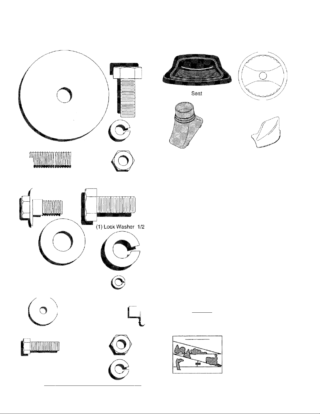
CONTENTS OF HARDWARE PACK
Parts Bag contents shown full size
(1) Hex Bolt
3/8-16x1
(1 ) Large Flat Washer (1 ) Lockwasher 3/8
(R
(1) Hex Bolt 5/16-18 X 1-1/4 (1) Locknut 5/16-18
(1 ) Shoulder Bolt
5/16-18
(1) Hex Bolt
1/2-13 X 1
Parts packed separately in carton
steering
Wheel
Steering
Boot
Video
Cassette
Mulcher
Plate
(1) Washer
17/32 X 1-3/16 X 12 Gauge
'
{2} Washers 3/16x3/4x16 Gauge
(2) Hex Bolts 1/4-20 x 3/4
#10x5/8 (2) Lock Washers #10
4 1
(2) Weld Nuts #10 "
(2) Hex Nuts
1/4-20
Manual Parts Bag
Parts bag contents not shown full size
(2) Washers 3/8
gZZJüi
(2) Shoulder
Bolts
Steering Wheel
Adapter
(2) Latch Hook
-------
1-1
Assemblys
\ LJ J X 7/8 X 14 Gauge
..
'X (2) Gauge
/ \ Wheels
V &Ì! ^í2)Center-
\ ^ lock Nuts
r ^Steering
e
Steering
Extension
Shaft
Wheel
Insert
(2) Washers
0/32 X 5/8 X 16 Gauge (2) Lock Washers 1/4
(2) Keys
Slope Sheet
Page 7
ASSEMBLY
Your new tractor has been assembled at the factory with exception of those parts left unassesiibisd for shipping purposes.
T0 ensure safe and proper operation of your tractor all parts and hardware you assemble must be tightened securely. Use
the correct tools as necessary to insure proper tightness, ’ '
TOOLS REQUIRED FOR ASSEMBLY
A socket wrench set will make assembly easier. Standard
wrench sizes are listed.
(1) 5/16" wrench
(2) 7/16" wrenches
(1) 1/2" wrench
(1) 9./16“ wrench
When right or isft hand is mentioned in this manual, it
means when you are in the operating position (seated
behind the steering wheel).
TO REMOVE TRACTOR FROM CARTON
UNPACK CARTON .
» Remove all accessible loose parts and parts cartons
from carton (See page 6).
• Cut, from top to bottom, along lines on all four corners
of carton, and lay panels flat.
• Check for any additional loose parts or cartons and
remove.
BEFORE ROLLING TRACTOR OFF SKID
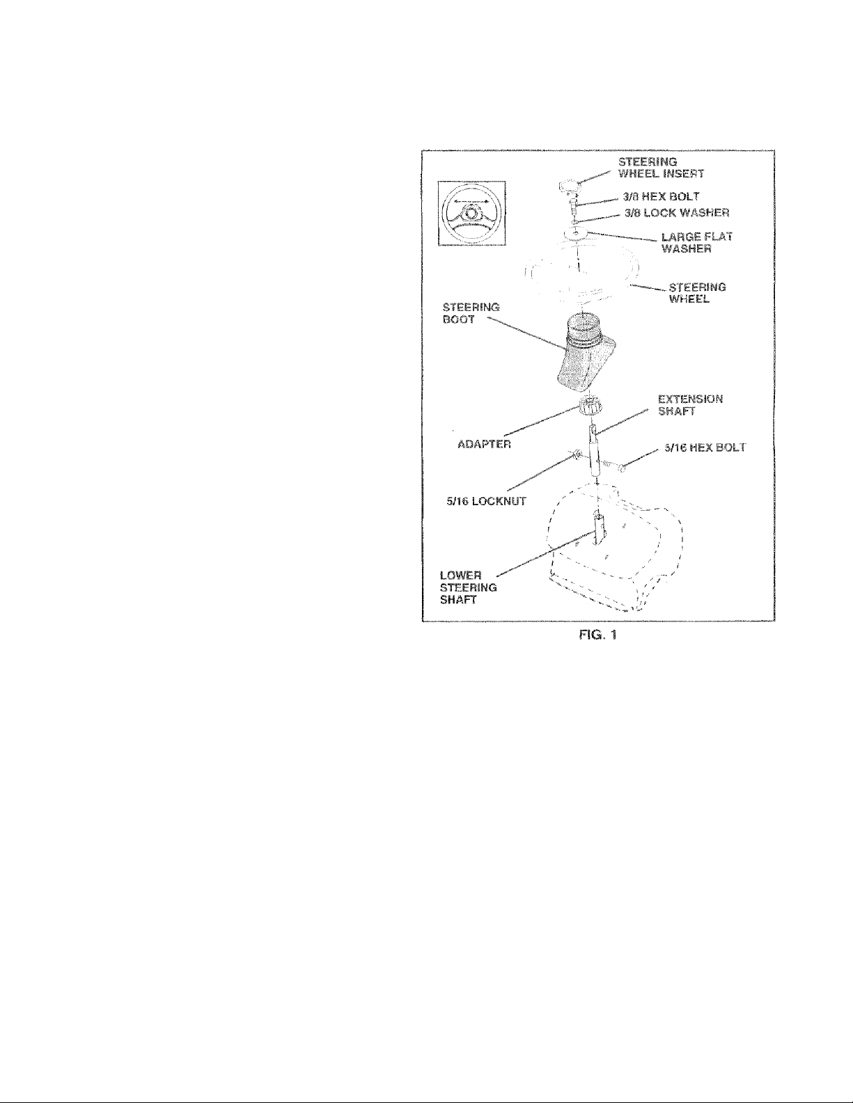
ATTACH STEERING WHEEL (See Fig. 1)
ASSEMBLE EXTENSION SHAFT AND BOOT
• Slide extension shaft onto lower steering shaft. Align
mounting holes in extension and lower shafts and
install 5/16 hex bolt and locknut. Tighten securely.
IMPORTANT: TIGHTEN BOLT AND NUT SECURELY TO
18-22 FT, LBS TORQUE.
» Place tabs of steering boot over tab slots in dash and
push down to secure.
INSTALL STEERING WHEEL
•• Position front wheels of the tractor so they are pointing
straight forward. .
“ Slide steering wheel adapter onto steering shaft exten
sion .
• Position steering wheel and sleeve assembly so cross
bars are horizontal (left to right) and slide onto adapter.
• Assemble large flat washer, 3/8 lock washer, 3/8 hex
bolt and tighten securely.
• Snap steering wheel insert into center of steering
wheel.
• Remove protective plastic from tractor hood and grill.
IMPORTANT: CHECK FOR AND REMOVE ANY STAPLES
IN SKID THAT MAY PUNCTURE TIRES WHERE TRACTOR
IS TO ROLL OFF SKID.
TO ROLL TRACTOR OFF SK!D (See Opera
tion section for location and function of con
trols)
• Press lift Sever plunger and raise attachment lift leverto
its highest position.
• Release parking brake by depressing dutch/brake
pedal.
’ Piace gearshift lever in neutral (N) position.
• Roll tractor backvirards off skid.
® Remove banding holding discharge guard up against
tractor. '
(1) 3/4" Socket w/drive rächet
Phillips Screwdriver
Tire pressure gauge
Utility knife
HOW TO SET UP YOLIB TRACTOR
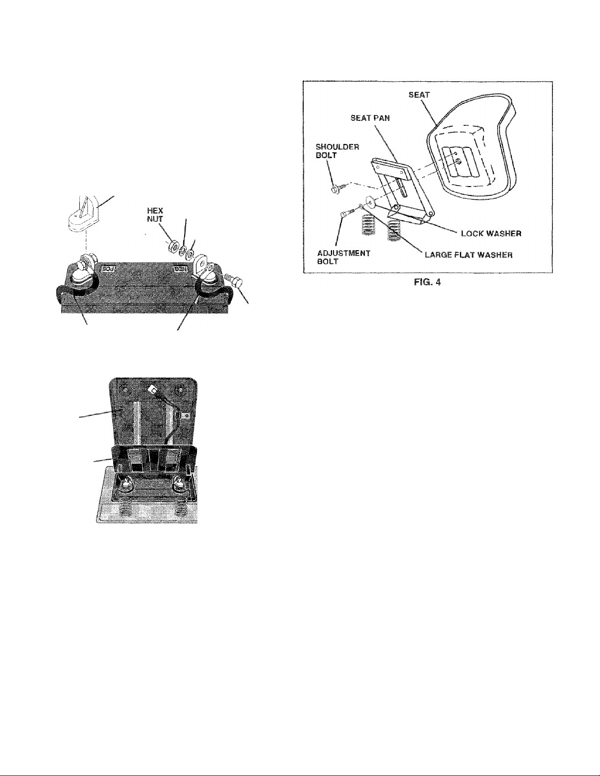
CONNECT BATTERY (See Figs. 2 and 3)
CAUTION: Do not short battery termi
nals. Before connecting battery, re
move metai bracelets, wristwaich
to
Remove cardboard packing from seat pan and lift seat
pan to raised position.
Open battery box door.
Remove terminal protective caps arrd discard.
If this battery is put into service after month and year
indicated on label (label located between terminals)
charge battery for minimum of one hour at 6-10 amps.
First connect RED battery cable to positive (+j terminal
with hex bolt, flat washer, lock washer and hex nut as
shown. Tighten securely.
Connect BLACK grounding cable to negative (-) termi
nal with remaining hex bolt, flat washer, lock washer
and hex nut. Tighten securely.
Close battery box door.
bands, rings, etc.
Positive terminal must be connected
first to prevent sparking from acciden
tal grounding.
Page 8
ASSEMBLY
Open battery box door for:
» Inspection for secure connections (to tighten hard
ware).
» Inspection for corrosion.
• Testing battery.
® Jumping (if required).
• Periodic charging .
DISCARD
TERyiNAL
PROTECTIVE
CAPS
LOCK
WASHER
FLAT
WASHER
HEX
BOLT
POSITIVE
(RED) CABLE
SEAT
PAN
BATTERY BOX DOOR
NECSATIVE
(BLACK) CABLE
FIG. 2
FIG.3
INSTALL SEAT (See Fig. 4)
Adjust seal before tightening adjustment bolt.
• Remove cardboard packing on seat pan.
• Place seat on seat pan and assemble shoulder bolt.
® Assemble adjustment bolt, lockwasherandflatwasher
loosely. Do not tighten.
• Tighten shoulder bolt securely.
• Lower seal into operating position and sit on seat.
® Slide seat until a comfortable position is reached which
allows you to press dutch/brake pedal all the way
down.
• .Get off seat without moving its adjusted position.
• Raise seat and tighten adjustment bolt securely.
CHECK TIRE PRESSURE
The tires on yourtractorwere overinflaled at the factory for
shipping purposes. Correct tire pressure is important for
best cutting performance.
• Reduce tire pressure to PSI shown in “PRODUCT
SPECIFICATIONS” on page 3 of this manual.
CHECK DECK LEVELNESS
For best cutting results, mower housing should be properly
leveled. See “TO LEVEL MOWER HOUSING" in the
Service and Adjustments section of this manual.
CHECK FOR PROPER POSITION OF ALL
BELTS '
See the figures that are shown for replacing motion and
mower blade drive belts in the Service and Adjustments
section of this manual. Verify that the belts are routed
correctly.
CHECK BRAKE SYSTEM
After you learn how to operate your tractor, check to see
that the brake is properly adjusted. See 'TO ADJUST
BRAKE" in the Service and Adjustments section of this
manual. '
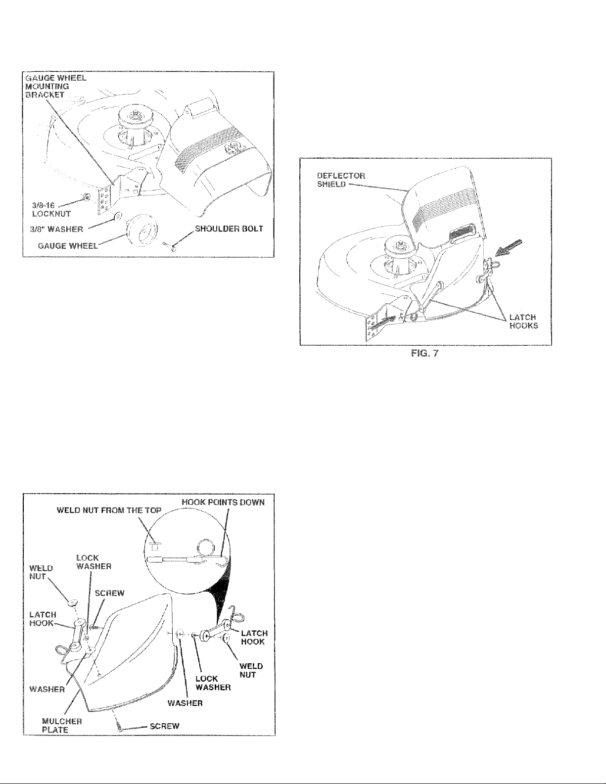
ASSEMBLE GAUGE WHEELS TO MOWER
DECK (See Fig. 5)
Assemble gauge wheels with tractor on aflat level surface.
• Adjust mower to desired cutting height {See ‘TO AD
JUST MOWER CUTTING HEIGHT" in the Operation
section of this manual).
• With mower in desired height of cut position, gauge
wheels should be assembled so they are slightly off the
ground. Install gauge wheel in appropriate hole with
shoulder bolt, 3/8" washer and 3/8-16 locknut and
tighten securely.
• Repeat for opposite side installing gauge wheel in
same adjustment hole. •
8
Page 9
ASSEMBLY
FiG. 5
¡INSTALL MULCHER PLATE
(See Figs. 6 7)
• install two latch hooks to mulcher plate using screw,
washer, lock washer, and weld nut as shown.
NOTE: Pre-assembie weld nut to latch hook by inserting
weld rrut from the top with hook pointing down.
• Tighten hardware securely.
• Raise and hold deflector shield in upright position.
• Place front of mulcher plate over front of mower deck
rjpenlng and slide into place, as shown.
• Hook front latch into hole on front of mower deck.
» Hook rear latch into hole on back of mower deck.
CAUTION: Do not remo¥6 discharge
guard from mower. Raise and hold
A
guard when attaching mulcher plate
and allow it to rest on plate while in
operation.
TO CONVERT TO BAGGING OB
DISCHARGING
Simply remove mulcher plate and store in a safe place.
Your mov/er is now ready for discharging or installation of
oplional grass catcher accessory,
NOTE: It is not necessary to change blades. The rriuicher
blades are designed for discharging and bagging also.
^CHECKLIST
BEFORE YOU OPERATE AND ENJOY YOUR NEW
TRACTOR. WE WISH TO ASSURE THA T YOU RECEIVE
THE BEST PERFORMANCE AND SA TISFACTiONFROM
THIS GUALITY PRODUCT
PLEASE REVIEW THE FOLLOWING CHECKLIST:
/ All assembly instruciions have been completed.
/ Nrj remaining loose parts in carton.
■/
Battery is properly prepared and charged, (Minimum
1 hour at 6 amps).
/ Seat is adjusted comfortably and tightened securely.
/ All tires .are properly inflated, (For shipping purposes,
the tires were overinflated at the factoiy).
/ Be sure mower deck is properly leveled side-to-side/
front-to-rear for best cutting results. (Tires must be
properly inflated for leveling).
/ Check mower and drive belts. Be sure they are routed
properly around pulleys and inside a!! belt keepers.
/ Check wiring. See that all connections are still secure
and wires are properly clamped.
WHILE LEARNING HOWTO USE YOUR TRACTOR. PA Y
EXTRA ATTENTION TO THE FOLLOWING IMPORTANT
ITEMS:
/ Engine oil is at proper level.
/ Fuel tank is filled with fresh, clean, regular unleaded
gasoline.
/ Become familiar with all controls - their location and
function. Operate them before you start the engine.
/ Be sure brake system is in safe operating condition.
FiG. 6
Page 10

OPERATION
These symbols may appear on your fractor or in literature supplied with the product. Learn and understand their meaning.
Q A
BATTERY
CAUTION OR REVERSE
WARNING
STOP
FORWARD FAST
SLOW
« a| a
ENGINE ON ENGINE OFF OIL PRESSURE CLUTCH LIGHTS ON LIGHTS OFF
!B l\l ©
FUEL
CHOKE MOWER HEIGHT DIFFERENTIAL PARKING BRAKE UNLOCKED
LOCK LOCKED
R N H L (®)|1
He
REVERSE NEUTRAL HIGH
I
MOWER LIFT
DANGER. KEEP HANDS AND FEET AWAY
ATTACHMENT
CLUTCH ENGAGED
LOW
HP
ATTACHMENT
CLUTCH DISENGAGED
HYDROSTATIC FREE WHEEL
(Hydro Models only)
PARKING BRAKE
Ml
IGNITION
10
Page 11
oPEEmcm
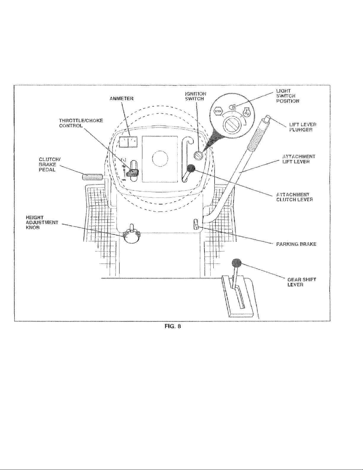
KNOW YOUR TRACVOR
READ THIS OWNER'S MANUAL AND SAFETY RULES EIEFORE OPERATING YOUR TRACTOR
Compare the illustrations with your tractor to familiarize yourself with the locations of various controls and adjusiments. Save
this manua! for future referertce.
Our tractors conform to the safety standards of the American National Standards institute.
ATTACHMENT CLUTCH LEVER: Used to engage the
mower blades, or other attachments mounted to your
tractor.
LIGHT SWITCH: Turns the headlights on and off.
THRQTTLE/CHOKE CONTROL: Used to control engine
speed.
CLUTCH/BRAKE PEDAL: Used for declutching and brak
ing the tractor and starting the engine.
PARKING BRAKE: Locks clutch/brake pedal into the
brake position.
GEAR SHIFT LEVER -• Selects the speed and direction of
the tractor.
ATTACHMENT LIFT LEVER; Used to raise and towerthe
mower deck or other attachments mounted to your tractor.
LIFT LEVER PLUNGER: Used to release attachment lift
lever when changing its position.
IGNITION SWITCH: Used for starting and stopping the
engine.
HEIGHT A.DJUSTMENTKNOB; Used to adjust the mower
cutting height.
AMMETER: Indicatas batterv charging
(-). ' ■'
{+)
or discharging
11
Page 12
OPERATION
The operation of any tractor can result in foreign objects thrown into the eyes, which can
result in severe eye damage. Always wear safety glasses or eye shields while operating your
tractor or performing any adjustments or repairs. We recommend a wide vision safety mask
over the spectacles or standard safety glasses.
HOW TO USE YOUR TRACTOR
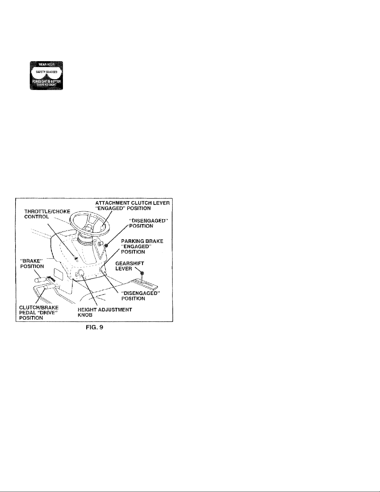
TO SET PARKING BRAKE (See Fig. 9)
Your tractor is equipped with an operator presence sensing
switch. When engine is running, any attempt by the
operator to leave the seat without first setting the parking
brake will shut off the engirie.
• Depress clutch/brake pedal into full “BRAKE” position
and hold.
• Place parking brake lever in “ENGAGED” position and
release pressure from clutch/brake pedal. Pedal should
remain in ‘BRAKE” position. Make sure parking brake
will hold tractor secure.
NOTE: Under certain conditions when tractor is standing
idle with the engine running, hot engine exhaust gases may
cause “browning” of grass. To eliminate this possibility,
always stop engine when stopping tractor on grass areas.
CAUTION: Always stop tractor com
pletely, as described above, before leav
ing
A
the operator's position; to empty
grass catcher, etc.
TO USE THROTTLE CONTROL (See Fig. 9)
Always operate engine at full throttle.
• Operating engine at less than full throttle reduces the
battery charging rate.
• Full throttle offers the best bagging and mower perfor
mance.
TO MOVE FORWARD AND BACKWARD
(See Fig. 9)
The direction and speed of movement is controlled by the
gearshift lever.
• Start tractor with clutch/brake pedal depressed and
gearshift lever in neutral (N) position.
• Move gearshift lever to desired position.
• Slowly release clutch/brake pedal to start movement.
IMPORTANT: BRING TRACTOR TO A COMPLETE STOP
BEFORE SHIFTING OR CHANGING GEARS. FAILURE
TO DO SO WILL SHORTEN THE USEFUL LIFE OF YOUR
TRANSAXLE.
STOPPING (See Fig. 9)
MOWER BLADES -
• Move attachment dutch lever to “DISENGAGED” po
sition.
GROUND DRIVE -
• Depress clutch/brake pedal into full “BRAKE" position.
• Move gearshift lever to neutral (N) position.
ENGINE -
• Move throttle control to slow position.
NOTE: Failure to move throttle control to slow
position and allowing engine to Idle before stopping may
cause engine to “backfire”.
• Turn ignition key to "OFF” position and remove key.
Always remove key when leaving tractor to prevent
unauthorized use.
• Never use choke to stop engine.
TO ADJUST MOWER CUTTING HEIGHT
(See Fig. 9)
The cutting height is controlled by turning the height adjust
ment knob in desired direction.
• Turn knob clockwise (y^) to raise cutting height.
• Turn knob counterclockwise (|f^) to lower cutting
height.
The cutting height range is approximately 1-1/2“ to 4". The
heights are measured from the ground to the blade tip with
the engine not running. These heights are approximate
and may vary depending upon soil conditions, height of
grass and types of grass being mowed.
• The average (awn should be cut to approximately 2-1 /2
inches during the cool season and to over 3 inches
during hot months. For healthier and better looking
lawns, mow often and after moderate growth.
• For best cutting performance, grass over 6 inches in
height should be mowed twice. Make the first cut
relatively high; the second to desired height.
12
Page 13
OPERATION
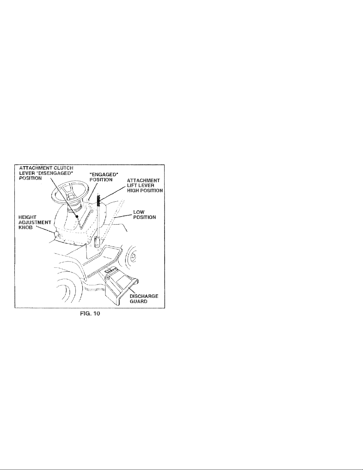
TO OPERATE MOWER (See Fig. 10)
Your tractor is equipped with an operator presence sens
ing sv/itch. Any attempt by the operator to leave the seat
with the engine running and the attachment clutch engaged
will shut off the engine.
* Select desired height of cut.
* Lower mower with attachment lift control,
® Start mower blades by engaging atiachment clutch
control,
* TO STOP MOWER BLADES - disengage attachment
clutch control.
CAUTION; Do not operate the mower
without either the entire grass catcher,
A
on mowers so equipped, or the dis
charge guard in place. ,
* To restart movement, slowly release parking brake and
clutch/brake pedal ’
* Mak.6 ail turns siowiy,
TO TRANSPORT
* Raise attachment lift to highest position with attach
ment lift control, '
* When pushing oriowing your tractor, be sure gearshift
lever is in neutra! (N) position.
* Do not push or tovif- tractor at more than five Í5) MPH.
NOTE; To protect hood from damage when transporting
yourtractoron a truck or atrailer, be sure hood is closed and
secured to tractor. Use an appropriate means of tying hood
to tractor (rope, cord, etc,),
BEFORE STARTING THE ENGINE
CHECK ENGINE OIL LEVEL (See Fig. 17)
» The engine in your tractor has been shipped, from the
factory, already filled with summer weight oil.
® Check engine oil with tractor o-n level ground.
* Unthread and remove oil fiii cap/dipstick; wipe oil off.
Reinsert the dipstick into the tube and rest oil fill cap on
the tube. Do not thread the cap onto the tube. Remove
and read oil level. If necessary, add oil until ’‘FULL”
mark on dipstick is reached Do not overfill
® For cold weather operation you should chanae oil for
easier starting (See “OIL VISCOSITY CHART in the
Customer Responsibilities section of this manual).
* To change engine oil, see the Customer Responsibili
ties section in this manual.
TO OPERATE ON HILLS
CAUTION: Do not drive up or down
hills with slopes greater than 15° and
A
Choose the slowest speed before starting up or down
hills.
Avoid stopping or changing speed on hills.
If slowing is necessary, move throttle control lever to
slower position.
If stopping is absolutely necessary, push clutch/brake
pedal quickly to brake position and engage parking
brake.
Move gearshift lever to 1st gear. Be sure you have
allowed room for tractor to roll slightly as you restart
movement.
do not drive across any slope.
ADD GASOLINE
- Fill fuel tank. Use fresh, clean, regular unleaded
gasoline with a minimum of 87 octane. (Use of leaded
gasoline will increase carbon and lead oxide deposits
and reduce valve life). Do not mix oil with gasoline.
Purchase fue! in quantities that can be used within 30
days to assure fuel fre,shness.
IMPORTANT; WHEN OPERATING IN TEIVlPERATURES
BELOW 32''F(0“C), USE FRESH, CLEAN WINTER GRADE
GASOLINE TO HELP INSURE GOOD COLD WEATHER
STARTING.
WARNING; Experience indicates that alcohol blended
fuels (called gasohol of using ethanol or methanoi} can
attract moisture which leads to separation and formation of
acids during storage. Acidic gas can damage the fuel
system of an engine while in storage. To avoid engine
problems, the fuel system should be emptied before stor
age of 30 days or longer. Drain the gas tank, start the
engine and let it run until the fuel lines and carburetor are
empty. Use fresh fuel next season. See Storage Instruc
tions for additional information. Never use engine or
carburetor cleaner products in the fuel tank or permanent
damage may occur.
CAUTION: Fill to bottom of gas tank
filler neck. Do not overfill. Wipa off any
A
spilfecJ al! or fuel. Do not store, spill or
use gasoline near ati open flame.
13
Page 14
OPERATION
TO START ENGINE (See Fig. 9)
When starting the engine for the first time or if the engine
has run out of fuel, it will take extra cranking time to move
fuel from the tank to the engine.
• Depress clutch/brake pedal and set parking brake.
• Place gear shift lever in neutral (N) position.
® Move attachment clutch to “DISENGAGED” position.
• Move throttle control to choke (|\1) position.
Note: Before starting, read the warm and cold starting
procedures below. ,
• Insert key into ignition and turn key clockwise to “ST ART’
position and release key as soon as engine starts. Do
not run starter continuously for more than fifteen sec
onds per minute. If the engine does not start after
several attempts, move throttle control to fast (^)
position, wait a few minutes and try again. If engine still
does not start, move the throttle control back to the
choke (|\|) position and retry.
WARM WEATHER STARTING (50° F and above)
• When engine starts, move the throttle control to the fast
{<%) position.
• The attachments and ground drive can now be used. If
the engine does not accept the load, restart the engine
and allow it to warm up for one minute using the choke
as described above.
COLD WEATHER STARTING ( 50° F and below)
• When engine starts, allow engine to runwith the throttle
control in the choke (|\j) position until the engine runs
roughly, then move throttle control to fast (■%») position.
This may require an engine warm-up period from
several seconds to several minutes, depending on the
temperature.
• The attachments can also be used during the engine
warm-up period.
NOTE; If at a high altitude {above 3000 feet) or in cold
temperatures (below 32 F) the carburetor fuel mixture may
need to be adjusted for best engine performance. See “TO
ADJUST CARBURETOR” in the Service and Adjustments
section of this manual.
MOWING TIPS
• Tire chains cannot be used when the mower housing is
attached to tractor.
• Mower should be properly leveled for best mowing
performance. See “TO LEVEL MOWER HOUSING” in
the Service and Adjustments section of this manual.
• The left hand side of mower should be used for trim
ming.
• Drive so that clippings are discharged onto the area
that has been cut. Have the cut area to the right of the
machine. This will result in a more even distribution of
clippings and more uniform cutting.
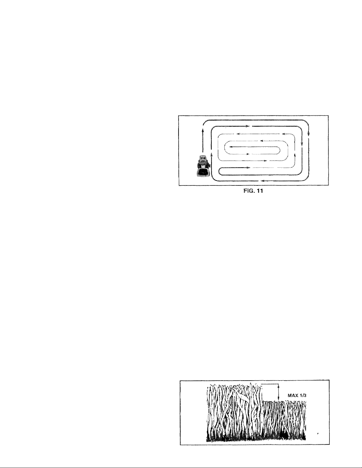
• When mowing large areas, start by turning to the right
so that clippings will discharge away from shrubs,
• fences, driveways, etc. After one or two rounds, mow
in the opposite direction making left hand turns until
finished (See Fig. 11 ).
• If grass is extremely tall, it should be mowed twice to
reduce load and possible fire hazard from dried clip
pings. Make first cut relatively high; the second to the
desired height.
Do not mow grass when it is wet. Wet grass will plug
mower and leave undesirable clumps. Allow grass to
dry before mowing.
Always operate engine at full throttle when mowing to
assure better mowing performance and proper dis
charge of material. Regulate ground speed by select
ing a low enough gear to give the mower cutting
performance as well as the quality of cut desired.
When operating attachments, select a ground speed
that will suit the terrain and give best performance of
the attachment being used.
MULCHING MOWING TIPS
IMPORTANT: FOR BEST PERFORMANCE, KEEP
MOWER HOUSING FREE OF BUILT-UP GRASS AND
TRASH. CLEAN AFTER EACH USE.
■ The special mulching blade will recut the grass clip
pings many times and reduce them in size so that as
they fall onto the lawn they will disperse into the grass
and not be noticed. Also, the mulched grass will
biodegrade quickly to provide nutrients for the lawn.
Always mulch with your highest engine (blade) speed
as this will provide the best recutting action of the
blades.
• Avoid cutting your lawn when it is wet. Wet grass tends
to form clumps and interferes with the mulching action.
The best time to mow your lawn is the early afternoon.
At this time the grass has dried and the newly cut area
will not be exposed to the direct sun.
• For best results, adjust the mower cutting height so that
the mower cuts off only the top one-third of the grass
blades (See Fig, 12). For extremely heavy mulching,
reduce your width of cut and mow slowly.
» Certain types of grass and grass conditions may re
quire that an area be mulched a second time to cdmpletely hide the clippings. When doing a second cut,
mow across or perpendicular to the first cut path.
• Change your cutting pattern from week to week. Mow
north to south one week then change to east to west the
next week. This will help prevent matting and graining
of the lawn.
FIG. 12
14
Page 15

CUSTOMER RESPONSIBILITIES
MAmiEMAMCE SCHEDULE
FILL IN DAITS
AEÍ YOU CO!v1Ft.tfE
ret^l'lam service
Clifirb Bi-sh- Onerbti'jn
L,ht;Ur U|,; Pfbvj'qre
Chf ck for L.-j-Lst- Fasteners
EOarrierr'Hepld''.fc- Mnw>ir F3lades
1 i.hricb.Fior ChRrt
Ci’C-r k Lf.‘7'3№e5harge
"'L'-ari R.tttery 3rd Tbitriinals
■ThPCi' Tr^nsavifl Crr.hog
Mdjijbt Blrfr,;. Bfcitr.j T-nqi.'jn
a-qju-t M'lfinn Hnir.-j Beiiti.r) Tension
fU.F.i.L Fwqnf. Oil
Ciiqm: Engine Oil
c;is-,-Ui Air 'OlTftr
Cltati eir Scrqe-ii
iri; fif-rl i./iiilflr'r Spark Arrestor
pKpl'.eP Oil f-ilier (If rt(|uipped)
rioan fcnginfc! i.o"ling Fins
Replacs Spark Plug
Replace Air Filter Paper Cartridge
Replace Fuel Filler
I" Change niore often operailrg under a heavy load or in high arnbient iemperalures, 5 - If equipped with adjustsbirr systesTu
f. • Service r!ior«> often when operating in dirty or dusty conditions.
3 - M equipped with oil ch^inge oil every 50 hours,.
4 " Replace b'adss more often when mowing in sandy soil,
✓ ✓
✓
✓
✓
✓
✓
✓ 7
✓
✓ 4
✓
✓
✓
✓ s
✓
1^23
✓ k
1
✓ ^
1/2
✓
1^,2
✓ 2
✓
✓
✓ i
✓
6 ■ Not required i equipped with mainteitance- tres battsty.
7 -■ Tigtiten troist axie pivot bolt (t> 7,5 f|,-lbr, niarsirmim.
Do not ovsrtigtiseri.
DATES
,
1
1
1
1
I
Í
1
____
1
1
1
i
GENERAL RECOMMENDATIONS
The warranty on this tractor does not cover items that have
been subjected to operator abuse or negligence. To
receivefull value from the warranty, operaiormust maintain
tr,actor as instructed in this manual.
Some adjustments will need to be made periodically to
properly maintain your tractor.
All adjustments in the Service and Adjustments section of
this manual should be checked at least once each season.
» Once a year you should replace the spark plug, clean
or replace air filter, and check blades and belts for
wear. A new spark plug and clean air filter assure
proper air-fuel mixture and help your engine run better
and last longer,
BEFORE EACH USE
• Check engine oil level.
• Check brake operation,
® Check tire pressure.
• Check for loose fasteners.
LUBRICATION CHART
{Dspinole zerk-
©FRONT WHEEL'
BEARING 2ERK
©ATTACHMENT-
CLUTCH
PIVOT(S)
© SAE 30 OR 10W30 MOTOR OIL
© GENERAL PURPOSE GREASE
REFER TO CySTOMEB RESPONSIBILITIES "ENGINE” SECTION
IMPORTANT; DO NOT OIL OR GREASE THE PiVOT POINTS
WHICH HAVE SPECIAL NYLON BEARINGS, ViSCOUS LUBRI
CANTS WILL ATTRACT DUST AND DIRT TH.AT WILL SHORTEN
THE LIFE OF THE SELF-LUBRICATING 3E.ARINGS. IF YOU
FEEL THEY MUST BE LUBRICATED, USE ONLY A DRV. POW
DERED GRAPHITE TYPE LUBRICANT SPARINGLY.
15
SPINDLE ZERK©
FRONT WHEEL©
BEARING 2ERK
'ENGINE @
ÖEASSHIFT©
PIVOTS
Page 16
CUSTOMER RESPONSIBILITIES
TRACTOR
Always observe safely rules when performing any mainte
nance.
BRAKE OPERATION
If tractor requires more than six (6) feet stopping distance
at high speed in highest gear, then brake must be adjusted.
(See 'TO ADJUST BRAKE” in the Service and Adjust
ments section of this manual).
TIRES
• Maintain proper air pressure in all tires (See “PROD
UCT SPECIFICATIONS" on page 3 of this manual).
• Keep tires free of gasoline, oil, or insect control chemi
cals which can harm rubber.
• Avoid stumps, stones, deep ruts, sharp objects and
other hazards that may cause tire damage.
BLADE CARE
For best results mower blades must be kept sharp. Re
place bent or damaged blades.
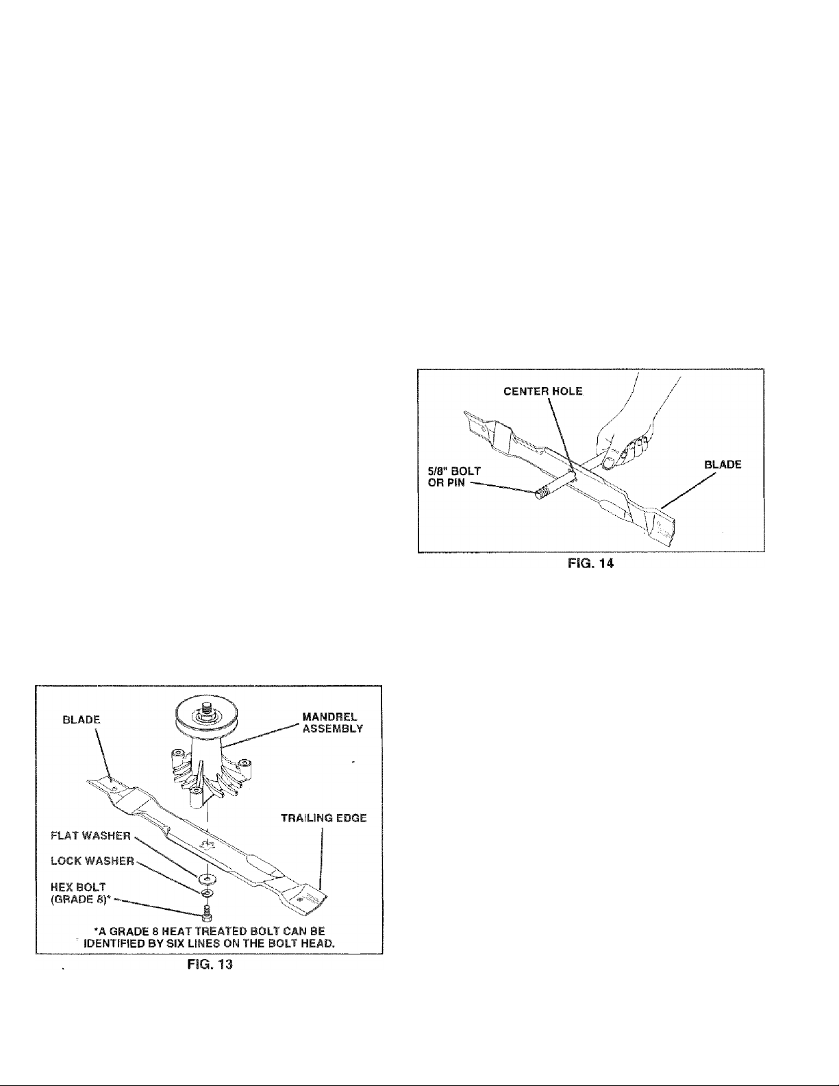
BLADE REMOVAL (See Fig. 13)
• Raise mower to highest position to allow access to
blades.
• Remove hex bolt, lock washer and fiatwashersecuring
blade.
• install new or resharpened blade with trailing edge up
towards deck as shown.
• Reassemble hex bolt, lock washer and flat washer in
exact order as shown.
• Tighten bolt securely (30-35 Ft. Lbs. torque).
IMPORTANT; BLADE BOLT IS GRADE 8 HEATTREATED.
NOTE: We do not recommend sharpening blade - but if you
do, be sure the blade is balanced.
TO SHARPEN BLADE (See Fig. 14)
Care should be taken to keep the blade balanced. An
unbalanced blade w/ill cause excessive vibration and even
tual damage to mower and engine.
• The blade can be sharpened with a file or on a grinding
wheel. Do not attempt to sharpen while on the mower.
• To check blade balance, you will need a 5/8“ diameter
Steel bolt, pin, or a cone balancer. (When using a cone
balancer, follow the instructions supplied with bal
ancer).
• Slide blade on to an unthreaded portion ofthe steel bolt
or pin and hold the bolt or pin parallel with the ground.
If blade is balanced, it should remain in a horizontal
position. If either end of the blade moves downward,
sharpen the heavy end until the blade is balanced,
NOTE: Do not use a nail for balancing blade. The lobes of
the center hole may appear to be centered, but are not.
BATTERY
Your tractor has a battery charging system which is suffi
cient for normal use. However, periodic charging of the
battery with an automotive charger will extend its life.
® Keep battery and terminals clean.
» Keep battery bolts tight,
• Keep small vent holes open.
• Recharge at 6-10 amperes for 1 hour.
TO CLEAN BATTERY AND TERMINALS
Corrosion and dirt on the battery and terminals can cause
the battery to “leak” power. ,
® Open battery box door.
• Disconnect BLACK battery cable first then RED bat
tery cable and remove battery from tractor.
• Rinse the battery with plain water and dry.
• Clean terminals and battery cable ends with wire brush
until bright.
• Coat terminals with grease or petroleum jelly.
• Reinstall battejy (See “CONNECT BATTERY" in the
Assembly section of this manual).
16
Page 17
CUSTOMER RESPONSIBILITIES
V-BELTS
CheckV 'beltsfordeterioralionand wear after 100 hours of
operation and replace it necessary. The belts are not
adjustable. Replace belts if they begin to slip from wear.
TRANSAXLE COOLING
Keep transaxie free from build-up of dirt and chaff which
can restrict cooling.
ENGINE
LUBRICATION
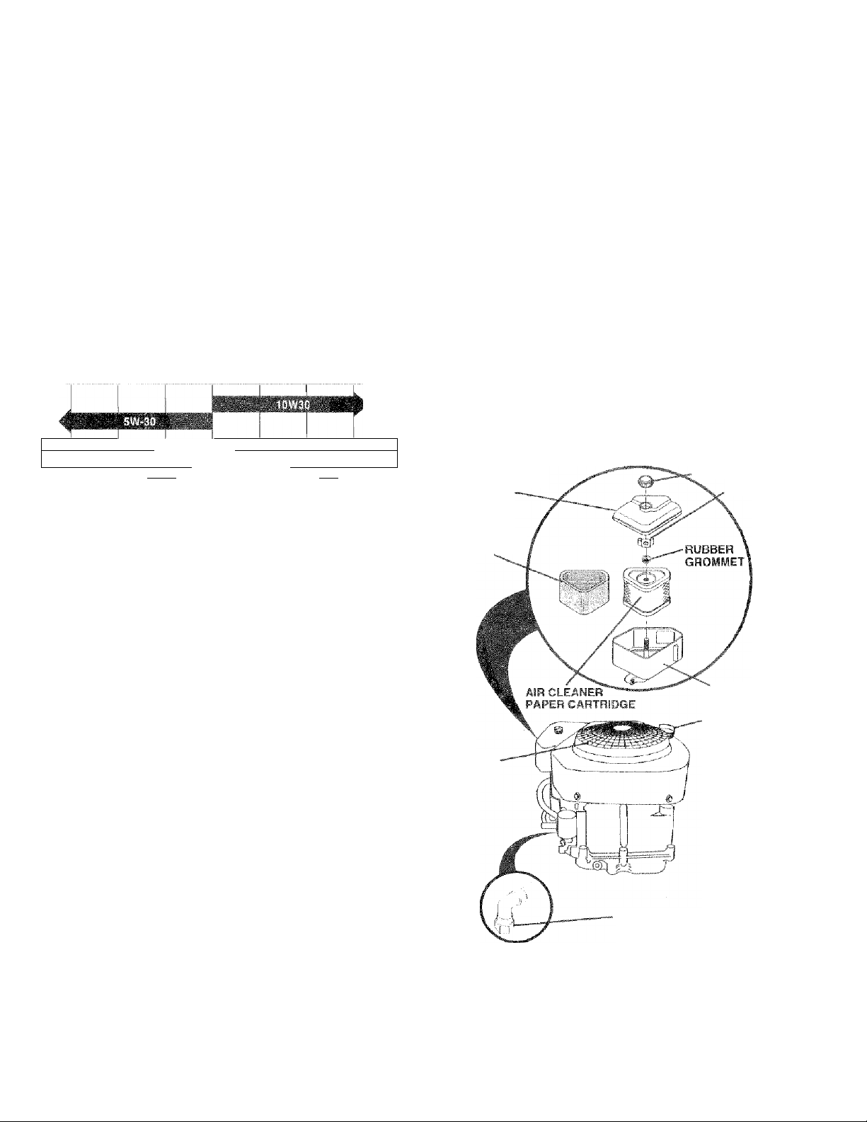
Only use high quality detergent oil rated with API service
classification SF orSG. Select the oil’s SAE viscosity grade
according to your expected operating temperature,
SAE VISCOSITY GRADES '
f=F V
'"C ^0- -20" 0 10'^
0'^ O'- 10
TEMPERATURE hAMCE ANTICIPATED BEFORE_NEXT 0!L CHANGE
'■•T' V
FIG. 15
eo‘
20-’ 30'^ 40®
iOO"
TO CHANGE ENGINE OIL (See Figs. 15 and 16)
Dste-rmirie temperature range expected before oil change.
Ail oil must meet API service classification SF or SG,
Be .sure tractor is on level surface.
Oil will drain more freely when warm.
Catch oil in a suitable container.
Remove oil fill cap/dipstick. Be careful not to allow dirt
to enter the engine when changing oil.
Remove drain plug.
After oil has drained completely, replace oil drain plug
and tighten securely.
Refi!! engine with oil through oil fill dipstick tube. Pciur
slowly. Do not overfill. For approximate capacity see
“PRODUCT SPECIFICATIONS" on page 3 of this
manual.
Use gauge on oi! fill cap/dipstick for checking level.
Insert dipstick into the tube and rest the oil Rii cap on the
tube. Do not thread the cap onto the tube when taking
reading. Keep oil at “FULL” line on dipstick. Tighten
cap onto the tube securely when finished.
AIB CLEAWEB
COVER
COVER KNOB
WING NUT
NOTE: Although multi-viscosity oils (5W30, 10W30 etc.)
improve starting in cold weather, these multi-viscosity oils .
will result in increased oil consumption when used above
32"F, Check your engine oil level more frequently to avoid
possible engine damage from running low on oil.
Change the oil after the first two hours of operation and
every 50 hours thereafter or at least once a year if the
tractor is not used for 50 hours in one year.
Check the crankcase oil level before starting the engine
and after each eight (8) hours of operation. Tighten oil fill
cap/dipstick securely each time you check the oil level.
FOAM
PHE-CLEAMER
AIR
SCFIEEN
'AIR CLEANER
BASE
OIL FILL
CAP/OiPSTICK
0!L DRAIN
PLUG
17
FIG. 16
Page 18

CUSTOMER RESPONSIBILITIES
CLEAN AIR SCREEN (See Fig. 16)
Air screen must be kept free of dirt and chaff to prevent
engine damage from overheating. Clean with a wire brush
or compressed air to remove dirt and stubborn dried gum
fibers.
AIR FILTER (See Fig. 16}
Your engine will not run properly using a dirty air filter.
Clean the foam pre-cleaner after every 25 hours of opera
tion or every season. Service paper cartridge every 100
hours of operation or every season, whichever occurs first.
Service air cleaner more often under dusty conditions.
• Remove knob and cover.
• Remove wing nut and air cleaner from base.
TO SERVICE PRE-CLEANER
• Slide foam pre-cleaner off cartridge.
• Wash it in liquid detergent and water.
• Squeeze it dry in a clean cloth.
• Saturate it in engine oil. Wrap it in clean, absorbent
cloth and squeeze to remove excess oil.
TO SERVICE CARTRIDGE
« Gently tap the flat side of the paper cartridge to dis
lodge dirt. Do not wash the paper cartridge or use
pressurized air, as this will damage the cartridge.
Replace a dirty, bent, or damaged cartridge.
• Reinstall the pre-cleaner (cleaned and oiled) over the
paper cartridge.
• Reassemble air cleaner, wing nut, cover and tighten
knob securely.
CLEAN AIR INTAKE/COOLING AREAS
To insure proper cooling, make sure the grass screen,
cooling fins, and other external surfaces of the engine are
kept clean at all times.
Every 100 hours of operation (more often under extremely
dusty, dirty conditions), remove the blower housing and
other cooling shrouds. Clean the cooling fins and external
surfaces as necessary. Make sure the cooling shrouds are
reinstalled.
NOTE: Operating the engine with a blocked grass screen,
dirty or plugged cooling fins, and/or cooling shrouds re
moved will cause engine damage due to overheating.
MUFFLER
Inspect and replace corroded muffler and spark arrester (if
equipped) as it could create a fire hazard and/or damage.
SPARK PLUGS
Replace spark plugs at the beginning of each mowing
season or after every 100 hours of operation, whichever
occurs first. Spark plug type and gap setting are shown in
“PRODUCT SPECIFICATIONS” on page 3 of this manual.
18
Page 19

CUSTOMER RESPOMSIBILITIES
ENGINE OIL FILTER (See Fig. 17}
Replace the engine oil fitter even/ season or every other oii
change if the tractor is used more than 100 hours in one
year.
* Drain oil from engine crankcase (See ‘TO CHANGE
ENGINE OIL in this section of this manual, through
step remove drain plug).
• Remove oil filter and wipe off filter adapter.
* Apply a thin coating of new engine oil to the rubber
gasket on replacement oil fitter.
• Instaii replacement oil filler on filter adapter. Turn oil
filter clockwise until rubber gasket contacts !he filter
adapter, then tighten filter an additional 1/2 turn.
‘ Fill crarrkcase with new oil (See “TO CHANGE EN-
CalFdE OIL.’" in this section of this manual). For approxi
mate capacity see “PRODUCT SPECIFICATIONS’“ on
page 3 of this mamja!.
» Start the engine and check for oil leaks. Correct any
leaks before placing engine into full operation.
m-Um FUEL FILTER (See Fig. ia)
The tuol filter should De replaced once each season. If fuel
filter becofTies dcgned, obstruciing fuel flow to carburetor,
rfap'lacement
With engine cool, remove filter and plug fuel iine
sections.
• Place new fuel filter in position in fuel line with arrow
pointing towards carburetor.
® Be sure there are no fuel line leaks and clamps are
properly positioned.
is
required.
F!6.18
CLEANING
« Clean engine, battery, seat, finish, etc. of all foreign
matter.
• Keep finished surfaces and wheels free of all gasoline,
oil, 8tC-
® Protect painted .surfaces with automotive type wax.
We do not recommend using a garden hose to dean your
tractor unless the electrical system, muffler, air filter and
carburetcrr are covered to keep water out Water in engine
can result in a ,shortened engine life.
19
Page 20

SERVICE AND ADJUSTMENTS
CAUTION: BEFORE PERFORMING ANY SERVICE OR ADJUSTMENTS:
• Depress clutch/brake pedal fully and set parking brake.
• Place gearshift lever in neutral (N) position.
A
TRACTOR
TO REMOVE MOWER (See Fig. 19)
Mower will be easierto remove from the right side of tractor.
• Place attachment clutch in "DISENGAGED” position.
• Move attachment lift lever forward to lower mower to its
lowest position.
• Roll belt off engine pulley.
• Disconnect clutch rod from dutch lever by removing
retainer spring.
• Disconnect anti-sway bar from chassis bracket by
removing retainer spring.
• Disconnect suspension arms from rear deck brackets
by removing retainer springs.
• Disconnect front links from deck by removing retainer
springs.
• Raise lift lever to raise suspension arms. Slide mower
out from under tractor.
IMPORTANT. IF AN ATTACHMENT OTHER THAN THE
MOWER IS TO BE MOUNTED TO THE TRACTOR,
REMOVE THE FRONT LINKS.
• Place attachment clutch in “DISENGAGED” position.
• Turn Ignition key "OFF” and remove key.
• Make sure the blades and all moving parts have completely stopped.
• Disconnect spark plug wire from spark plug and place wire where it cannot come in contact with
plug. ■
TO INSTALL MOWER (See Fig. 19)
• Raise attachment lift lever to its highest position.
• Slide mower undertractorwith discharge guard to right
side of tractor.
• Lower lift lever to its lowest position.
• Install mower in reverse order of removal instructions.
20
Page 21

SERVICE AND ADJUSTMENTS
TO LEVEL MOWER HOUSING
Adjust the mower while tractor is parked on level ground or
driveway. Make sure tires are properly inflated (See
“PRODUCT SPECIFICATIONS” on pageSofthis manual).
If tires are over or underinflated, you will not properly adjust
your mower.
SIDE-TO-SIDE ADJUSTMENT (See Figs. 20 and 21)
® Raise mower to its highest position.
® At the midpoint of both sides of mower, measure height
from bottom edge of mowerto ground. Distance “A” on
both sides of mower should be the same or within 1/4"
of each other.
® if adjustment is necessary, make adjustment on one
side of mower only.
• To raise one side of mower, tighten lift link adjustment
nut on that side. .
• To lower one side of mower, loosen lift ¡ink adjustment
nut on that side,
NOTE; Each full turn of adjustment nut will change mower
height about 1/8”.
• Recheck measurements after adjusting,
BOTTOM EDGE
OF MOWER TO
GROUND
BOTTOM EDGE
OF MOWER TO
GROUND
A ^
T:
r ^
GROUND LINE
FRONT-TO-BACK ADJUSTMENT {See Figs. 22 and 23)
IMPORTANT: DECK MUST BE LEVEL SIDE-TG-SIDE, iF
THE FOLLOWING FRONT-TO-BACK ADJUSTMENT IS
NECESSARY. BE SURE TO ADJUST BOTH FRONT LINKS
EQUALLY SO MOWER WILL STAY LEVEL SIDE-TOSIDE.
To obtain the best cutting results, the mower housing
should be adjusted so that the front ¡.s approximately 1/4“ to
3/4" lower than the rear when the mower is in its highest
position.
Check adjustment on right side of tractor. Measure dis
tance “D” directly in front and behind the mandrel at bottom
edge of mower housing as shov/n.
» Before making any necessary adjustment-s, check that
both front links are equal in length. Both links should be
approximately 10-3/8".
» If links are not equal in length, adjust one link to same
length as other link.
* To lower front of mower loosen nut “E” on both front
links an equal number of turns.
» When distance ‘'D” is 1/4" to 3/4" lower at front than
rear, tighten nuts “’F” against trunnion on both front
links.
* To raise front of mower, loosen nut “F" from trunnion on
both front links. Tighten nut "E" on both front links ari
equal number of turns.
® When distance “D” is 1/4" to 3/4" lower at front than
rear, tighten nut “F” against trunnion on both front links.
* Recheck side-to-side adjustment.
MANDREL
FIG. 21
|1 ..
21
FIG. 23
Page 22

SERVICE AND ADJUSTMENTS
TO REPLACE MOWER BLADE DRIVE BELT
(See Fig. 24)
The mower blade drive belt may be replaced without tools.
Park the tractor on level surface. Engage parking brake.
BELT REMOVAL -
• Remove movs/er from tractor (See ‘TO REMOVE
MOWER" in this section of this manual).
• Work belt off both mandrel pulleys and idler pulleys.
• Pull belt away from mower.
BELT INSTALLATION -
• Install new belt in reverse order of removal.
• Make sure belt is in all pulley grooves and inside all belt
guides.
• Install mower in reverse order of removal instructions.
TO REPLACE MOTiON DRIVE BELT
(See Fig. 26)
Park the tractor on level surface. Engage parking brake.
For assistance, there is a belt installation guide decal on
bottom side of left footrest.
• Remove mower (See TO REMOVE MOWER" in this
section of this manual.)
• Remove upper belt keeper.
• Remove belt from stationary idler and clutching idler.
• Pull belt slack toward rear of tractor. Remove belt
upwards from transaxle pulley by deflecting belt keep
ers.
• Pull belt toward front of tractor and remove downwards
from around engine pulley.
• install new belt by reversing above procedure.
IMPORTANT; MAKE SURE UPPER BELT KEEPER IS
POSITIONED PROPERLY BETWEEN LOCATOR TABS.
TO ADJUST BRAKE (See Fig. 25)
Your tractor is equipped with an adjustable brake system
which is mounted on the right side of the transaxle.
If tractor requires more than six (6) feet stopping distance
at high speed in highest gear, then brake must be adjusted.
• Depressdutch/brake pedal and engage parking brake.
• Measure distance between brake operating arm and
nut “A” on brake rod.
• if distance is other than 1 -1 /2", loosen jam nut and turn
nut "A" until distance becomes 1-1/2". Retighten jam
nut against nut “A”.
• Road test tractor for proper stopping distance as stated
above. Readjust if necessary. If stopping distance is
still greater than six (6) feet in highest gear, further
maintenance is necessary. Contact your nearest au-
^ thorized service center/department.
Page 23

5;4r|b..-~iL: Uiii-UJ-i HHR-bb iUib
-js,^ ’ M«bn! iTvio '’Vj... :,“i .diîj
■ il M. '! I, h ' h^uS. It eii'Mf.'r-ii."Nc I 'J’^f’fi'r'f ^
iH‘i ; r <-i;t"-’:f h ii li ¡',.") 5--,}i".Mii T!,;c-J|tf’ .' ■:
i’■he 1 i ..-îî i se ■> c-J-''
\ u ■ f * • Î jIh'A V
t r., i!-.: - t'. r. ■ r. I‘* '( .'III-.I l'’^)
' I. . • r 1 . i w f ri' -i" K' hf- 'j '
• “ii! , C'-iiib> [iKl !if>T! >jfMi.Ji!t k~',vi !" 1 i' !* ''V ' fr
h . !. r*'“ ‘i f' n S' I Î- 'nc ih
» righ-ren !oci<nu!3 securely.
es'Mêr- eifT ? £' i'Ep
. ¡jr^uTeij.
u,ics, ra,s
FIG. 27
b }' UrNO¥F. TAILLJ Ft.'F
■ boj ,.d:
G ' I j[ .1 'ii,
b m..'- 'Sf,iclufiiingnnc ¡111 /
bed r*-isv.t3( UÉ.” f • -o.rjii s s eg > r* b-i
or |-
t '-po'r fur ■.eo'st.mtG
,n r'r,r Viherî- niy ugncroovhc n rear'A'hei.i f:Lb
. r-o n 'k iti^' n -^quoi-' fiO'
■ P ".vrlv-îS ~.n'i ‘VC-if fct uriiig iPCj oewj-« I-’ i'!
axle groove.
® Ffepiace axle cover.
TO ADJUST STEERING WHEEL ALIGNMENT
!f steering wheel crossbars are not horizontal (left to right)
when wheels are positioned straightforward, remove steer
ing wheel and reassemble per instructions in the Assembly
scîction of this rnarsual.
FRONT WHEEL TQE-IN/CAMSER
Thfi front wheel toe-in and camber are not adjustable on
your treictor, !f damage has occurred to affect the front
wheel toe-in or camber, contact your nearest authorized
service centsr/deparimenî.
TO. START ENGINE WITH A WEAL E-fATTERY
(See Fig. 30)
CAISTIOI'I: Leiad-srrid fcatterse-*? gener™
ote erxplosive gases. Keepsparhs, flame
arjcf srsiokin.g №31611.31.3 away from bat
A
If your baltery rs too wo.ak trs start the engine, it should be
recharyod. If "jumper cebims' are usofi for emergency
siailMig. follow Ihio procedure-'
IMFOPTAHT 7GUP TRACTOR iS EUiilPPftP WITH A
12 VOLT NEGATIVE GROUNDER S'f-STEM. THE OTHER
VEiHiCLE MUST ALSO Bff A 12 VOLT NFGATIVE
OnOUNDEO Sy'STEM DO HOT USE YOUR TRACTOR
PATTL-R'Y to .start DTHEFi VEHICLES,
TO ATTACH JUMPER, CABLES -
• Connect each end of the RED cable to the POSITIVE
(+) terminal of each battery, taking care not to short
against chassis, '
® Connect one end of the BLACK cable to the NE-IGA~
TIVE (-} terminal of fully charged battery.
• Connect the other end of the E-LACK cable to good
CHASSIS GROUND, awayfromfueltankand battery.
TO REMOVE CABLE-3, REVELRSE ORDER -
® BLACK cable first from chassis and then irom the fully
charged battery.
• RED cable test from both batteries.
teries. Aiwaifs iMear eye pretecliori
wEsen around bati0rle.s.
23
Page 24

SERVICE AND ADJUSTMENTS
MEGATIWTERMINAL
CHASSIS"
CABLES
CHARGED
BATTERY
TERMINAL
POSITIVE
TERMINAL
. %r
/ \ NEGATIVE
FIG. 30
TO REPLACE HEADLIGHT BULB
• Raise hood.
• Pull bulb holder out of the hole in the backside of the
grill
• Replace bulb in holder and push bulb holder securely
back into the hole in the backside of the grill.
® Close hood.
TO REPLACE FUSE
Replace with 30 amp automotive-type plug-in fuse. The
fuse holder is located behind the dash.
TO REMOVE HOOD AND GRILL ASSEMBLY
(See Fig. 31)
• Raise hood.
• Unsnap headlight wire connector.
• Stand in front of tractor. Grasp hood at sides, tilt toward
engine and lift off of tractor.
® To replace, reverse above procedures.
INTERLOCKS AND RELAYS
Loose or damaged wiring may cause your tractor to run
poorly, stop running, or prevent it from starting.
• Check wiring. See electrical wiring diagram in the
Repair Parts section of this manual.
24
Page 25

%
CM-Jrf
1L. ^ c f f
The thro ili- o
J
‘"M Lt
necessaiJ, proce
f. M c
' '
I
'
tH ’ J
T" ’>J J® C ».i’' U LfjEi •I'-f-r ù’® '
•■S' f. t 1 1 h. ^ [i- ■ n . I -I > l * ia !i I . tn ^ <'j i '
ntf rt I.Oi b-, I. . ^
scr
i.c 2 PieiTS ^
t
«* ^
^ i.
! iTroi
)' ilU' ri h
)u!
G,r
i 1
Iti F
r.'jinr hoi
' h'
i 1 1esare 3taL( t
k j !
,t A
' 1 ’>
* -
i -aS* p
fj if !
H-
ikto s 681 tiOleÌI Ihi'i
• i
et c^J'8
the i'l
it lit
f! fiG
"i tif
f
)C
i" iW,
Bbk
[
ft'“''
L..
ep,
b"
r
» '
i
t
Ì, '
i<
.i
f ^
M
ti
t
1 ^
?■ •
‘;ho
,i
I I It M-ri ,
^ hIHB
ìBCi
i
nSifii>
i l' i i chrk ii
3 ut
3 ryiT'
)ve ii
td A i
:he fsi
, ■■ A h
--L.
¡'G,
1 Oj
Si cdjiiil 1 fit 1
mu - b 'lit
1
' ' lll(
d 1
’
r-f
jsor
' 1 ■
i 1
t i
t'’ M» h >
1 "k
■
i [i J f 1 P
'b't
Ì ^
no inhl.'lM ok
. S 1 f-f J| '
i f
1
Hi .i I'-l I'lrSii (U '
^ IT ^
^lory arid
’ 7
1. ■ 1 r
Ifij ill t
If' ) • f-tl
t;tf i- ' H
1 Lhf
MIS t '!
*' '1(-i'|J,r Jh'Cn.>'lj f f i If JiÌii’T-' I.C .!' ti -I
‘i '!![..r t‘Jit <!'' IL'. "i It I'tf-i I |h, ,
cSUiUt-.tlli'i-rili.. d;:i iUlHJVVt».
In genera!, turning the adjusting needles in (clockwise)
decreases the supply cl iuel to the erìgine giving a leaner
fuel/air mixture. Turning tne adjusting needles out (counter
clockwise) increases the supply of fuel to the engine giving
a richer fuei/air mixture,
iMPORTANT: DAMAGE TO TltE NEEDLES .AND THE
SEATS IN CARBURETOR MAY RESULT IF NEEDLE IS
TURNED IN TOO TIGHT.
l‘•lCУrE: The carburetor on this engine is low emission, it is
equipped with an idle fuel adjusting needle with a Simiter
cap, which allows some adjustment within the limits allowed
by ihe cap. Do not attempt to remove the limiter cap. Ths
iimiter cap cannot be removed without breaking the adiusiirig
needle,
* Be sure you have a clean air filter and the throttle
control cable is adjusted properly (see above).
* Star!: engine and allow to ‘warm for five minijtes. Make
.adjustments with engine running and shift'motion control
lever in neutral (N) position.
* idle speed setting - With throttle control lever in slov»'
i‘m)
position, engine should idle at 1750 RPM. It
engirfO ¡dies too slow or fast, turn idle speed adjusting
screw in or out until correct idle is attained. ^
« Idle fuel needle setting - With throttle control fever in
slow (•«») position, turn idle fuei adjustment needle in
(clockwise) until engine begins to die and then turo out
(counterclockwise) until engine runs rough. Turn neeclle
to a point midway between those two positions.
® Recheck idle speed. Readjust if necessary.
' " r •> ,-p!iE-T
“ h ■ ,H 'E'K lÈii '■r ' u I f i « tn jiOA I -K. G I joM .
ir •! I ' - O I u - h 'it- ] ft- Si i ^ V I' I J‘ '
■ rir ^ ¡-1- 1 . r • I ! ! kWIS‘ ! I > it'T - < -
- . ® uu mH V Uj. i n,\ UK
,fl ' .r . > n f 1 '
*■ j ‘ I " 1 . , if '.m To r-.'t ayi i
' m • 'Tu"'' b *''k
i r f Y ’ l i T , r ‘ i f i i y r - U T r ’ " ' t E E i i ' ' , U ! E
• 1 ' r i . ‘ I ■‘U roc or ,i < .F
* ' * f t • f f 1 ,1 i I J f? L D '
‘ -F ' * Uiiil"ivFf i'lc -3 ri Ip"*
■"ri'l trffj o'. ‘G ijT _ liA'. '*
1 > „
r U* n SI H'l H , V r Ì ' ' u 1 ' L r f G ["■“'■’fEL
i
L " ' i- ' , _LU i L.M
. lU- Gfl V H .! H , ' < ‘ h ^ •.Uirbll .¡1
Ml F
I I T ! o
MAKE
Fie. 32
FIS. 33
"I lb
Mir-
25
Page 26

STORAGE
Immediately prepare your tractor for storage at the end of
the season or if the tractor will not be used for 30 days or
more.
CAUTION: Never store the tractor with
gasoline in the tank inside a building
where fumes may reach an open flame
A
or spark. Allow the engine to cool
before storing in any enclosyre.
TRACTOR
Remove mower from tractor for winter storage. When
mower is to be stored for a period of time, clean it thor
oughly, remove all dirt, grease, leaves, etc. Store in a
clean, dry area,
• Clean entire tractor (See “CLEANING” In the Customer
Responsibilities section of this manual).
• Inspect and replace- belts, if necessary (See belt re
placement instructions in the Service and Adjustments
section of this manual).
• Lubricate as shown in the Customer Responsibilities
section of this manual.
• Be sure that all nuts, bolts and screws are securely
fastened. Inspect moving parts for damage, breakage
and wear. Replace if necessary.
• Touch up all rusted or chipped paint surfaces; sand
lightly before painting.
BATTERY
• Fully charge the battery for storage.
• After a period of time in storage, battery may require
recharging.
• To help prevent corrosion and power leakage during
long periods of storage, battery cables should be
disconnected and battery cleaned thoroughly (see “TO
CLEAN BATTERY AND TERMINALS” in the Cus
tomer Responsibilities section of this manual).
• After cleaning, leave cables disconnected and place
cables where they cannot come in contact with battery
terminals.
• Be sure battery drain tube is securely attached.
• If battery is removed from tractor for storage, do not
store battery directly on concrete or damp surfaces.
ENGINE
FUEL SYSTEM
IMPORTANT: IT IS IMPORTANT TO PREVENT GUM
DEPOSITS FROM FORMING IN ESSENTIAL FUEL
SYSTEM PARTS SUCH AS CARBURETOR, FUEL FILTER,
FUEL HOSE, OR TANK DURING STORAGE, ALSO,
EXPERIENCE INDICATES THAT ALCOHOL BLENDED
FUELS (CALLED GASOHOL OR USING ETHANOL OR
METHANOL) CAN ATTRACT MOISTURE WHICH LEADS
TO SEPARATION AND FORMATION OF ACIDS DURING
STORAGE. ACIDIC GAS CAN DAMAGE THE FUEL
SYSTEM OF AN ENGINE WHILE IN STORAGE.
• Drain the fuel tank.
• Start the engine and let it run until the fuel lines and
carburetor are empty.
• Never use engine or carburetor cleaner products in the
fuel tank or permanent damage may occur,
• Use fresh fuel next season,
NOTE: Fuel stabilizer is an acceptable alternative in
minimizing the formation of fuel gum deposits during stor
age. Add stabilizer to gasoline in fuel tank or storage
container. Always follow the mix ratio found on stabilizer
container. Run engine at least 10 minutes after adding
stabilizer to allow the stabilizer to reach the carburetor. Do
not drain the gas tank and carburetor if using fuel stabilizer.
ENGINE OIL
Drain oil (with engine warm) and replace with clean engine
oil. (See “ENGINE” in the Customer Responsibilities
section of this manual).
CYLINDERS
Remove spark plug(s).
Pour one ounce of oil through spark plug hole(s) into
cylinder(s).
T urn ignition key to “ST ART" position fora few seconds
to distribute oil.
Replace with new spark p)ug(s).
OTHER
Do not store gasoline from one season to another.
Replace your gasoline can if your can starts to' rust.
Rust and/or dirt in your gasoline will cause problems.
If possible, store your tractor indoors and cover it to
give protection from dust and dirt.
Cover your tractor with a suitable protective cover that
does not retain moisture. Do not use plastic. Plastic
cannot breathe which allows condensation to form and
will cause your tractor to rust.
IMPORTANT: NEVER COVER TRACTOR WHILE ENGINE
AND EXHAUST AREAS ARE STILL WARM.
26
Page 27

■f Hi« iHLi'/--H!i ■• 1 i ^‘Om íi
PROBLEM CAUSE
Will Ewt start t '. (i ■. ii.ii,*
2 i-r O'n«: m ■'• гl^t FÏJ’’ prof,-ar;y
3. l'rqMiñ 1f/3: i
4. i.")'j ’Jí a<f'
iji.;.
6. üi.¡y(i'-"i!:.',
’,if.
7. .■/■■ii ¡ !ii ‘•.'í '
8. i.ooKíi or ijqiTiaoí-a wirírig,
9. C-irt'íirefcr oui oí adiusimenl
ÍO EfíCúno valves su! of adiuslmeni.
Kürr? le Sfeï'î
r:nc|l!ie will not turn over Chjtoh/ijrake pedal not da pressed.
-I , r¡ f í I ■
2.. ij -L'A i ■)[ J
3.
4.
5. cF ;t,ii 1
a.
Jh 'k 'M W
D'li (II flit. 1 ■: " 'iue! fil'ier.
1 f il ro ■■
. at Mfi *■'1 t.ii ! V iKimsni.
tirigine valvas c
.Aifachnient clutch ts angaged.
Weak Of dead batleiy.
Blov/n (use.
Corroried battery terminate.
Loose or damafied wiring.
Faully ignition sviitch,
F’aulty soifinoid or starSer,
Faulty operator presence switohies)
“ 1/
rf! uising
!f of ■-'idiUÍ'ÍlTí .n!, 1 '
CORRECTION
I 1. Fill !ue! tank.
I 2. See ‘TO ST.tyRT ENOiME" In Operation sectiori,
I 3, Wait severe! rniriutss bekee ailsmpiing to start.
I 4. Replace spark plug
I fv Cliran/replafXi aii filicr
I f>, R-spiacs fusS fiKer,
I 7, Drain fuel tank anri '.^arbufefof. I'.sF!! lank wiit'i fcjsl-i
I oasokne Jind reptac'; fiioi fijs:!'.
I B, Check all wirirtq.
I 9, Sad “To Afiiusi Garbufs-ilcr' in f7sr>/ine Aoiustrnsnts
I sectioti.
j SO, ,;in- ,ai„iihO!'iz«d service csritar/'risspartrnerit
1. Cíean/replací
frepfacc spark plug.
! •
' !■
i '
P.er)
Tte" F--1
r onf- »’4
B or replace b,atiery.
Drain tu
,ii tank and fcTiil vnJh Iresfi go sol'■w.
fhi.iT :
! wiring
Adjusî Carburetor" sn SanfcG AciirîRtîTierii
ih autl'iorisort irfitvice (‘.anfer/deparîmscit.
’1“'
Depress ciL:?ch./bta.t-o pedal.
Disengage attachment dutch.
Recnaige c-r reDtar'e b.-iftery.
Replace fuse.
Cisan battery tsmrlnals.
Check al! wiring.
Check/replacs ignition switcfi.
CTiecfcfrepiacs ,solenoid or irtarfar.
Contact an authorized sewico cfsiiter/departfueni
Engine clicks but will not I 1. Weak or dead battery,
start I 2, Corroded battery terminal:
Loss of power
3. Loose or damaged wiring.
4. Faulty soiGnoid or starter.
Gutting too riHJch gr,ass./loo fast.
Throttle in "CHOICE' posiBon.
Build-up of grass, leaves and trash under mower.
Dirty air filter.
Low oil level/riiity' oil,
Faully spark plug.
Ditty tue! filter.
Stale (rr dirty fuel.
Wafer in fuel
Spai'k. plug wire loose.
Dirty engine air screerv'fins.
Dirty.telogged muffler.
Leese ot rtarnaged wiring.
Carburetor out of adjustn-ient.
15. Engine valves out of adjusttnent.
E,»eessive vibratlwri
1. Worn, bent or ioose bisde.
2. Bent blarls mandrei.
3. Loose/damagsd pari'(s).
1, Recharge or replace battery.
2. Clean battery termináis.
3, Ct'iock al! wiring.
4. Cf'ienkyrtipiace soierioid or .ctarler
S6» In "Highw Cut" posi't'on/redycs spead.
Adjust throttle control.
Clean underside of mower housing.
Claanheplrsce air fflter.
Check nil level/change oil.
Cl73ari and ?egap or ch.anga spark piug.
Replace fuel filter.
Drain fuei tank and refill with fre,sii gasciirie
Drain fuel tank and carburetor, reliii tank with fresh
gasoline and replace fuel filter.
10
Conneejt and tighian spark plug wire.
11
Clean engine air screea'fins,
12
Clean/replace miifflff.
Check all vrinrig.
13
14
See “To Artjust CarhureioG in Service Adjustments
section.
15
Contact an authorized service centerfdapartment.
Heplacs blade, 'Tighlsn blade bolt.
Replace blade maneiret
Tighten looss part(s). Replace dainagsc! pgirfs.
27
Page 28

TROUBLESHOOTING POINTS
PROBLEM
Engine continues to run
when operator leaves seat
with attachment clutch
engaged
Poor cut - uneven
Mower blades will not
rotate
Poor grass discharge
CAUSE
1. Faulty operator-safety presence control system.
1. Worn, bent or loose blade.
2. Mower deck not level,
3. Buildup of grass, leaves, and trash under mower.
4. Bent blade mandrel.
5. Clogged mower deck vent holes from buildup of
grass, leaves, and trash around mandrels.
1. Obstruction in clutch mechanism
2. Worn/damaged mower drive belt.
3. Frozen idler pulley.
4. Frozen blade mandrel.
1. Engine speed too slow.
2- Travel speed too fast,
3. Wet grass.
4. Mower deck not level.
5. Low/unevsn tire air pressure.
6. Worn, bent or loose blade.
7. Buildup ot grass, leaves and trash under mower.
8. Mower drive bait worn.
9. Blades improperly installed,
10. Improper blades used.
11. Clogged mower deck vent holes from buildup ot
grass, leaves, and trash around mandrels.
CORRECTION
1. Check wiring, switches and connections. If not
corrected, contact an authorized service center/
department
1, Replace blade. Tighten blade boll
2, Level mower deck.
3, Clean underside of mower housing.
4, Replace blade mandrel,
5, Clean around mandrels to open vent holes.
1. Remove obstruction.
2. Replace mower drive belt
3. Replace idler pulley.
4. Replace blade mandrel.
1. Place throttle control in "FAST” position.
2. Shilt to slower speed.
3. Allow grass to dry before mowing,
4. Level mower deck.
5. Check tires for proper air pressure.
6. Replace/sharpen blade. Tighten blade bolt.
7. Clean underside of mower housing.
8. Replace mower drive belt.
9. Reinstall blades sharp edge down.
10, Replace with blades listed in this manual.
11. Clean around mandrels to open vent holes.
Headlight(s) not working
(if so equipped)
Battery will not charge
Engine “backfires”
when turning engine
"OFF”
1. Switch is "OFF”,
2. Bulb(s) burned out.
3. Faulty light switch.
4. Loose or damaged wiring.
5. Blown ¡use.
1, Bad battery cell (s),
2. Poor cable connections. .
3. Faulty regulator (if so equipped).
4, Faulty alternator.
1. Engine throttle control not set at "SLOW”
position for 30 seconds before stopping engine.
1. Turn switch “ON”.
2. Replace bu!b(s).
3. Check/repiace light switch.
4. Check wiring and conneclions.
5. Replace (use.
1. Replace battery.
2. Check/dean all connections.
3. Replace regulator.
4. Replace alternator.
1, Move throttle control to “SLOW" position and allow
to idle for 30 seconds before stopping engine. '
28
Page 29

SCHEMATIC
TRACTOR - - MODEL NUMBER 917.256644
RED
4
-O
BATTERY
FUSE 30 AMP.
CLUTCH/BRAKE
(PEDAL UP)
K) i
K) '
lQ4-
. . j
BLACK
lev-
-Y
BLACK
ATTACHMENT
CLUTCH
(CLUTCH OFF)
SEAT SWITCH
(NOT OCCUPIED)
GROUNDING
CONNECTOR
IGNITION SWITCH
POSITION CIRCUIT
OFF
RUN/LIGHT
HUN
START
Q M 4“ L NONE
B-p L
B+ L NONE
B-p L-p S NONE
“MAKE”
A-p Y
, v..A...A^A^_veW;-
AFTER FIRE SOLENOID
CHARGING srSTHM OinPUT
3 AMP DC @ 3600 RPM
LIGHTING SYSTEM OUTPUT
S AMP AC e 3600 RPM
NON-REMOVABLE
CONNECTIONS
REMOVABLE
CONNECTIONS
WIRING INSULATED CLIPS
NOTE; !F WIRING INSULATED
CLIPS WERE REMOVED FOR
SERVICING OF UNIT, THEY
SHOULD BE REPLACED TO
PROPERLY SECURE YOUR
WIRING
IGNITION
UNIT
DIODE
■ 14 VOLT.S AC MIN & .3500 RPM (LIGHTS OFF)
BROWN
SPARK
-o
PLUG
ZB VOLTS AC MIN. « 3600 FIPM
(CHARGING -SYSTEM DISCONNECTED»
ALTERNATOR
,-AA\
fó ¿i—
NOTE
YOUR TRACTOR IS EQUIPPED WITH
A SPECIAL ALTERNATOR SYSTEM.
THE LIGHTS ARE NOT CONNECTED
TO THE BATTERY, BUT HAVE THEIR
OWN ELECTRICAL SOURCE.
BECAUSE OF THIS, THE BRIGHTNESS
OF THE LIGHTS WILL CHANGE WITH
ENGINE SPEED. AT IDLE THE LIGHTS
WILL DIM. AS THE ENGINE IS
SPEEDED UP, THE LIGHTS WILL
BECOME THEIR BRIGHTEST.
AL_A..A..y-
y HEADLIGHTS
rti
29
Page 30

' . ■ .'-I V:
' ' í.r „
’ ■ MODEL NUMBER Í17„256544
30
Page 31

REPAIR PARTS
ELECTRICAL
TRACTOR - MODEL NUMBER 917.256544
KEY PART
NO. NO.
1 146140 Battery 12 Volt 30 Amp
2 74760412 Bolt, Hex Head 1/4-20 unc x 3/4
3 STD551025
4 STD551125 Washer
6
STD541025 Nut
7
109238X
8
144940 Case, Battery W/2 Holes W/Br!y
109596X
9
15
147688 Fastener Snap-In
16 153664 ■
19 STD551125
73350400
20
21 147430
22
4152J Buib, Light
24 4799J
146147
25
26
108824X Fuse, 30 Amp
28 4207J Cable, Ground, 6 Gauge, Black, 12"
29
121305X Switch, Plunger
30 140301
31
124211X
32
141226 Cover, Key Switch
33 109310X
36 STD601005 Screw
38
140336 Bracket, Interlock Switch
39 109553X Switch, Interlock, Clutch, 4 Terminal
40
151212
41 71110408
42
131563
43
145673 Solenoid
44
73640400 Nut Keps Blk Hex 1/4-20 UNC
45
121433X Ammeter Rectangular 5 Amp
52 141940
70 142291 Harness Engine LT PL Kohl Cmd-I
NOTE: Ail component dimensions given in U.S. inches
1 inch = 25.4 mm
DESCRiPTiON
Washer
Tube, Piastic, 12"
Clamp, Hose
Switch Interlock Push-In
Washer. Lock
Nut, Hex, Jam 1/4-20 UNC
Harness, Light Socket
(includes 4152J)
Cable, Battery, 6 Gauge, Red, 11"
Cable, Battery, 6 Gauge, Red, W/
16 Wir
Switch, Ignition
Nut, Ignition
Key, Ignition
Harness, Ignition
Bolt, Hex Head, Fin. 1/4-20 x 1/2
Cover, Terminal, Red
Protection Wire Loop (Hour Meter)
HL
31
Page 32

■;'Г:
•■'TO t%
MODEL MIIMBER 917.256544
?î ..L--....,.
N „ ■■
0 '''■■Е''-''E'L''L--
X;
í^iL
Page 33

REPAIR PARTS
TRACTOR - MODEL NUMBER 917.256544
CHASSIS AND ENCLOSURES
KEY
NO. NO. DESCRIPTION
10 72140608 ■ Bolt, Carriage 3/8-16 x 3/4
11
12
13 146962
14 17490608
15 74180512
16 STD541431 Nut
17 144983X558
24
25 19131312
26 STD541437 Nut
28
29 145199
30 147310X558 Fender
31
33 145244X558
34
35 STD533707 Bolt
38 139886 Pivot Bracket Assembly, L.H.
39 139887
40 139977
51 73800400
52 19091416
53
54 17030814 Screw Spiderlock Hex Hd #8-7/8
55 145202
57 74780412 Bolt Fin Hex 1/4-20 UNC x .75
60
74
140
- -
PART
1 151169 Chassis Assembly
2 140356
3 17490612 Screw, Thd. Roll. 3/8-16 x 3/4
4 19131216
5 146077
6 145206
8
126471X Clip Insulator ,406 Mtg Hole
9
147633X010 Dash
146956
145660 Clip Tinnerman Grille P/L
STD523710 Bolt
145198X558 Grill
139976 Bracket, Fender Support
145243X558
145201
72140606
STD541437 Nut Crowntock 3/8-16 UNC
150556 Bracket Chassis Front 7 Ga.
5479J Plug, Button
Drawbar
Washer 13/32 x 3/4x16 Gauge
Bumper Snap-In
Saddle
Panel, Dash, L.H,
Panel, Dash, R.H.
Screw Thdrol 3/8-16 x 1/2
Screw, Machine. Truss Head
5/16-18 UNC X 3/4
Hood Assembly
Washer 13/32 x 13/16 x 12 Gauge
Lens, Grille
Footrest, L.H.
Footrest, R.H.
Pivot Bracket Assembly, R.H.
Spacer Fender Raised LT
Nut Lock w/lnsert 1/4-20 UNC
Washer 9/32 x 7/8 x 16 Ga.
Bracket Grille Pickoff LH
Bracket Grille Pickoff RH
Bolt Rdhd Sqnk 3/8-16unc x 3/4
NOTE: All component dimensions given in U.S. inches
1 inch - 25.4 mm
33
Page 34

DRICE34DRIVE
TRACTOR MODEL RÜMBErI §17A5Í544
Page 35

REPAIR PARTS
TRACTOR - - MODEL NUMBER 917.256544
KEY PART
NO. NO. DESCRIPTION
1
-------
— Transaxle, (See Breakdown)
Peerless, Model 930-057A
2 146682 Spring, Return, Brake
3 123666X Pulley, Transaxle
4 12000028 Ring, Retainer
5 1 21520X Strap, Torque
6 17490512 Screw, Thd., Roll. 5/16-18 x 3/4
8 141003 Lever, Shift
10 7602041B Pin, Cotter
11 105701X Washer, Shift Plate
13 74550412 Bolt 1/4-28 UNF W/Patch Grade 8
14 STD551125 Washer
15 74490544 Bolt Hex FIghd 5/16-18 Gr. 5
19 STD541437 Nut
21 106933X Knob
22 130804 Rod, Brake
24 STD541237 Nut
25 106888X Spring, Brake Rod
26 STD551037 Washer
27 STD561210 Pin
28 145204 Rod, Parking Brake
29 124236X Cap, Parking Brake, Red
30 130807 Bracket. Transaxle
31 127275X Keeper, Belt, L.H.
32 STD523107 Bolt
34 151128 Shaft Assembly, Foot Pedal
35 120183X Bearing, Nylon
36 STD551062 Washer
37 STD571810 Roll Pin
38 123674X Pulley, Idler, Flat
39 STD523727 Bolt
40 4470J Spacer, Split .395 x .59
41 153399 Keeper, Belt, Retainer
42 19131312 Washer 13/32 x 13/16 x 12 Gauge
44 105706X Bearing, Nylon
45 110812X Washer, Hardened
46 12000039 Ring, Klip
47 127783 Pulley, Idler. V-Groove, Plastic
48 12378&X Bellcrank Assembly
49 123205X Retainer, Belt
50 STD523715 Bolt
KEY PART
NO. NO.
51 STD541437
52 STD541431
53 10571 OX
55 105709X
56 STD523712
57 130801
58 127274X
59 140312
61 17490612
62 8883R
63 140186
64 71170764
65 STD551143
66 129921
70 134683
72 19132012
74 137057
75 121749X
76 STD581075
77 123583X
78 121748X
79 2228M
80 145090
81 145092
82 123782X
83 19171216
84 145643
85 150360
86 71208
87 19212016
88 12000008
89 139964
90 124346X
96 STD624003
110 74760612
112 19091210
113 127285X
116 72110610
NOTE: All component dimensions given in U.S. inches
DESCRIPTION
Nut Crown Lock 3/8-16 UNC
Nut Crown Lock 5/16-18 UNC
Link, Clutch
Spring, Clutch Return
Bolt Rn Hex 3/8-15 X 1-1/4
V"Beli, Ground Drive
Keeper, Belt, R.H.
Keeper, Belt, Center Span
Screw, Thd., Roll. 3/8-16 x 3/4
Cover, Pedal
Pulley, Engine
Bolt, Hex
Washer
Keeper, Belt, Engine, L.H.
Guide, Mower Drive Belt, R.H.
Washer 13/32 x 1 -1/4 x 12 Gauge
Spacer, Axle
Washer 25/32 x 1-1/4 x 16 Gauge
E-Ring
Key, Square 2.0 x .1845/, 1865
Washer 25/32 x 1-5/8 x 16 Gauge
Key Woodruff #9 3/16x3/4
Arm, Shift
Shaft Assembly
Spring, Torsion
Washer 17/32 x 3/4 x 16 Gauge
Tie Rod
Nut, Lock Center 1/4-28 FNTHD
Bushing, Pivot
Washer
E-Hing
Console, Shift, 6 Speed, N/Ignition
Nui, Self-Threading, Washer Hd 1/4
Retainer Spring 1" Zinc Cad
Bolt. Fin Hex 3/8-16 UNC x 3/4
Washer 9/32 x 3/4 x 10 Gauge
Strap Torque LT
Bolt Rdhd Sq Neck 38/-16 x 1.25
1 inch ~ 25.4 mm
35
Page 36

riEFi4lR FAF iA
STEERING ASSEMBLY
rr 2: "^IFI» MODEL ^fUMBER 917,256544
•- 42
l
23-
37-
44.,
51-
40^ M
>L,, "ft,.
7« /..
/ /' / t
11 / 24/.,„-
■'■ 40 / '
'■' 2®
Ali,
I -36
(■ . ‘-Ti
..
aV
... 22 . i’’
'"■■■ ,?"'i
46
\
16 32
.....
■'''7 A
/
14
13 ’
- ■ fO
11 -y-"
, ■ ■ i
\ :
'i4
'' 1.
№
\
i I
43
- / - '
"0-/'
/'0 ,l I
T43
/ /■■'-. 0 i
, r /• .
. ..’1J;‘
\ \
1 '
j
. 'Yv "
15
i
f /
/
/
■■ /
26-
S--.
9
...
.
..
/ /
/
i
■ 13
-—19
f"
i t
40"’
/"
/
28^'V"
/
10
2S
m
Page 37

REPAIR PARTS
STEERING ASSEMBLY
TRACTOR -
KEY
NO.
10
11 STD551137 . Washer, Lock
13 110438X
14
15
16 132624 Pin, Axle 5/8x1,55/1.54
17
18
19
20 12B684X Washer, Shim 1/4 x 5/8 x .062
21
22
23 127501 Pittman Shaft Assembly
24 109816X
25
26 126847X
27
28 19131416 Washer 13/32 x 7/8 x 16 Gauge
29 17490612 Screw, Thd., Roll. 3/8-16 x 3/4
30
32
36 132196 Bushing, Steering
37 152927
38 126805X
39
40 STD541537
41 100711L Adaptor, Steering Wheel
42 145054 Boot, Steering Shaft
43
44 153720 Extension Steenng LR/LT
46
47 6855M Fitting, Grease
51 73800500 Nut Lock Hx w/lnsert 5/16-18 UNC
54
62
63 STD523710 Boit Fin Hex 3/0-16unc x 1 Gr. 5
t^OTE: All component dimensions given in U.S. inches
PART
NO.
1 121472X
2
142033
135227
3
4 135228 Spindle Assembly, R.H.
5 6266H Bearing, Race, Thrust, Hardened
6 121748X
7
19272016 Washer 27/32 x 1-1/4 x 16 Gauge
8
12000029 Ring. Klip
9 336BR Bearing, Steering Column
130468 Link, Drag ,
74011056 Bolt, Hex Head 5/8-11 UNC x 3-1/2
73901000 Nut, Lock, Flange 5/8-11 UNC
140175
57079 Washer, Thrust .515 x .750 x ,033
124035X
STD551125 Washer
71100410 Screw, Cap. SCKT, Hd.
12403BX Bracket, Steering
136874 Gear, Sector
STD561210 Pin
130465
19133808 Washer 13/32 x 2-3/8 x 8 Gauge
121749X Washer 25/32 x 1-1/4 x 16 Gauge
121232X Cap, Spindle
74780520 Bolt Fin Hex 5/16-18UNC x 1-1/4
149686 Kit, Steering Assembly, Service
1 inch = 25.4 mm
MODEL NUMBER 917.256544
DESCRIPTiOM
Steering Wheel
Front Axle Assembly
Spindle Assembly, L.H.
Washer 25/32 x 1-5/8 x 16 Gauge
Spacer. Bearing. Front Axle
Shaft Assembly, Steering
Support, Shaft
Nyliner, Snap-In
Bushing, Link, Drag
Rod, Tie
Screw
Insert, Steering Wheel
Grtpco Nut
37
Page 38

SEAT ASSEMBLY
14.
TRACTOR MODEL NUMBER 917.256544
8
I
9->.
-.T
m
24.
As '
26... ' i
-16
"13
4? "'12
i -A- -
i-iy
.g
r-\
"25
23
KEY PART KEY
NO. NC5. DESCRIP'TION NO.
1
140123 Seal 15
2
140551
3
STD523710 Bolt 17
4
19131610 Washer J3/32 x 1 x 10 Gauge 21 153236
5 145006 Clip, Pusb-Sn Hinqed
Bracket. Pivoi. Seat
16
22 STD541431 Nut
6 STD541437 Nut 23
124181.x
7
8 17490616 Sc-rew, Thd., Roll. 3/8-16 x 1
19131614 Washer 13/32 x 1 x 14 Gauge 25
9
10 140552 Pan, Seat ' 26
Spring, Seat
24 19171912 Washer 17/32 x 1-3/16 x 12 Gauge
12 121246X Bracket, Switch Mounting
121243X
13 .
14 72050411 Bolt, Carnaoe 1/4-20 x 1-3/8
Bushing, Snap
NOTE: Ail componeni dirriensions given in U.S. inches
' A- ‘ SS-
part
-,4
-3
NO. DESCRIPTION
134300 Spacer, Split .28 x .88
121250X
123976X
Spring
Locknu!, Flange 1/4 Grade 5
Bolt, Shoulder 5/16-18 UNC
74780814 Boit, Hex Head, Fin.
1/2-13 X7./8 Grade 5
127018X Boll, Shoulder 5/16-18 x .62
STD551150
Washer, Lock
1 Irrch = 25,4 mm
38
Page 39

REPAIR PARTS
DECALS
20
%
TRACTOR - - MODEL NUMBER 917.256544
6 3
18
7. 18
10
KEY
NO.
10 137537
11 4900J
12 146046
13 147139
PART
NO. DESCRIPTION
140819
1
151299
3
4
151300
5
150333
6 133644
7 149407
8 151302
9 146709
^
--------
~3
Decal,
Decal,
Decal,
Decal,
Decal,
Decal,
Decal,
Decal,
Decal,
Decal,
Decal,
Decal,
11 8
-ZED.
21
\
Í5¡\
Operating Instruction
Hood, R.H.
Hood, LH.
Cap Cnsmr Help Line Srs
Customer Maintenance
Side Panel, Kohler
Mower, EZ3 Polo
Fender, Craftsman
Caution, English
Clutch/Brake, English
V-Belt Drive Schematic
Chassis, 6 Speed/42"
\ 1 ^
KEY
NO. NO.
14 136832
15 145245
17
18 151301
20 146710
21 138047
23 149516
..
_,
. .
PART
133179
145247
138311
155155
155156
DESCRIPTION
Decal, V-Belt Schematic
Pad Footrest Rbr Sq Craftsman
Decal, Mower QC System
Decal, Ins. Hood 15HP OHV Polo
Decal, Ins WhI Strg Auto Srs Gd
Decal, Battery Diehard Sears
Decal, Battery Dangr/Psn Srs. Eng
Fastener Pop in Footrest
Decal, Lift Handle
Owner's Manual, English
Owner's Manual, Spanish
WHEELS & TiRES
KEY PART
NO.
1
2 65139
3
4
5 106732X427
6 278H
7 9040H
8 105108X427
9
10
11 104757X
..
NOTE:
39
NO.
59192
106222X
59904
122082X
7152J
144334
All component dimensions given in U. S. inches
1 inch = 25.4 m-m
DESCRIPTION
Valve Cap, Tire
Stem,. Valve
Tire, Front
Tube, Front Tire
(Not Provided, Service Item Only)
Rim, Front
Fitting, Grease (Front Wheel Only)
Bearing, Flange (Front Wheel Only)
Rim, Rear
Tire, Rear
Tube, Rear Tire
(Not Provided, Service Item Only)
Cap, Axle
Sealant, Tire (10 oz. Tube)
Page 40

fitPMH PARTS
ENGINE
TRACTOR - - MODEL NUMBER 917.256544
80
77.
32-
31
40
P..
,
'46
‘33
" 37
29
33
'I
ii .
H I
V.-
23
^^
. o ^
1 Yr M , •'
^ X X
-X ^
'-X,
. ' Ti
^ ^ i
0 ^ . f
•'.'1 i
1 J
,1
6.
ri' -'
' 1 K>
s ov
OPTIONAL EQUIPMENT
Spark Arrester
35
40
Page 41

REPAIR PARTS
ENGINE
TRACTOR - - MODEL NUMBER 917.256544
KEY PART
NO. NO.
1
147025 Control, Throttle
2 17720410 Screw, Hex Head, Thread Cutting
------------
3
4 137350
13 Gasket, Exhaust (Order From
14 13280328 , , Nipple, Pipe 3/8 NPTx 3-1/2
15 13200300
16 STD551231 Washer
23 150554 Shield, Heat
29 137180 Arrestor, Spark
31
109202X Tank, Fuel
32 123549X Cap Assembly, Fuel Tank, Vented
33 123487X
35 17490512 Screw Thdrol. 5/16-18 x 3/4 TYT
37 137040 Line, Fuel
38
40 124028X Bushing, Snap, Fuel Line
44 17490412 Screw, Hex Washer Head, Thd.,
46 19091416 Washer 9/32 x 7/8 x 16 Gauge
—
DESCRIPTION
1/4-20x5/8
“
Engine, (See Breakdown) Kohler
Model No. CV14S, 41526
Muffler
Engine Mfgr.)
Elbow, Standard 90°, 3/8-18 NPT
Clamp, Hose
Plug, Oil Drain
(Order From Engine Manufacturer)
Roll.
1/4-20x3/4
62 STD551131 Washer, Lock
77
19101216 Washer 5/16 x 3/4 x 16 Ga.
M740108025
79
80 74760508
81
128861 Nut Flange 1/4-20 UNC Starter Nut
NOTE; All component dimensions given in U.S. inches
1 inch - 25.4 mm
Bolt Hex
Bolt Hex Hd 5/16-18 UNC x 1/2
41
Page 42

BEPAFi PARTS
MOWER LIFT
TRACTOR - - MODEL NUMBER 917.256544
29 ‘
28
T'
27
/
26
/
/
%J. /
PZ4
«■- /■
jf
/1
30
/ /
/
/
/ / /
// /
/ !
/ /
/
'■ y
/
/
20
.
1
6
■■'77^...............
15
iir 20 7
2
T
20 \
/
A
4
17I8
I5 . • ^
15
\
42
Page 43

REPAIR PARTS
MOWER LIFT
TRACTOR - - IflODEL NUMBER 917.256544
KEY
NO. NO, DESCRiPTION
PART
1
136973 Lift Lever Inner Wire Assembly
2 145117
3 105767X
4 12000002
5
19211621 Washer 21/32 x 1 x 21 Gauge
6
120183X Bearing, Nylon
7
125631X .
Shaft Assembly, Lift
Pin, Groove
E-Ring
Grip, Handle, Fluted
8 122365X Button, Plunger, Red
10
122512X Spring
11
139865
12
139866 Link, Lift, R.H.
13 STD624008 Retainer Spring
127218
15
16 73350800
17 130171
18 73800800
19 139868
20 STD624008 Retainer Spring
23
110807X Nut, Special
24
19131016
25 2876H
26
76020308
27
126971X Rod, Adjust, Lift
Link, Lift, L.H.
Link, Front
Nut, Hex, Jam 1/2-13 UNC
Trunnion
Locknut, Hex, with Washer Insert
1/2-13 UNC
Arm, Suspension, Rear
Washer 13/32 x 5/8 x 16 Gauge
Spring
Pin, Cotter 3/32 X 1/2
28 73350600 Nut, Hex, Jam 3/8-16 UNC
138057
29
30
150233 Trunnion, Depth Stop
31 140302
Knob, infinite Height Adjustment
Bearing, Pvt, Lift Spherical
32 73540600 Nut, Crownlock 3/8-24
145212
49
Nut, Hex Flange Lock
NOTE; All component dimensions given in U.S, inches
1 inch = 25.4 mm
43
Page 44

REPAIR PARTS
MOWER DECK
TRACTOR - - MODEL NUMBER 917.256544
117
Page 45

REPAIR PARTS
iWOWER DECK
TRACTOR - - MODEL NUMBER 917.25S544
KEY
NO. NO.
10
11
12 129895
13
14
15
16 140329
1?
18 72140505
19 132827
20
21
22 134753
23
24 105304X
25
26
27
28 19111016
29
30
31 129963
32
33
34
35
36
37 19131316
40
41 133551
43
44 140088
45
46
48 133944
49
50 131340
51 STD541410
52
53
PART KEY
DESCRIPTION
144393
1
STD533107 Bolt
2
138017
3
4
138440
STD624008
5
130832
6
850857
a
STD551137 Washer, Lock
9
140296 Washer, Hardened
134149
137645
128774
110485X Bearing, Ball, Mandrel
72110610
136888
STD541431 Nut Crownlock 5/16-18 UNC
131267
123713X
110452X Nut, Push
130968
131491
138776
153535
137266 Nut, Toplock, Flanged
STD533717 Bolt
133835
131494
STD541437 Nut Crownlock 3/8-16 UNC
140083
STD624003 Retainer
137729
133940
139888
131845
Mower Housing
Bracket Assembly,Sway Bar, Front
Bracket Assembly, Sway Bar
Retainer Spring
Arm, Suspension, Rear
Bolt, Hex 3/8-24 x 1.25 Grade 8
Blade, Mulching '
Bearing, Balt
Shaft Assembly, Mandrel, Vented
(Includes Key Number 6)
Housing, Mandrel, Vented
Stripper, Vented Mower Deck
Bolt, Carriage 3/8-16 x 1-1/4
Bolt, Carriage 5/16-18 x 5/8
Bolt, Shoulder
Baffle, Vortex
Stiffener Bracket
Bracket, Deflector
Cap, Sleeve
Spring, Torsion, Deflector
Shield, Deflector
Washer 11/32 x 5/8 x 16 Gauge
Rod, Hinge
Screw Thdrol Hex Head Zinc Mwr
Washer, Spacer
Pulley, Mandrel
Fastner, Christmas Tree
Pulley, Idler, Flat
Washer 13/32 x 13/16 x 16 Gauge
Rod, Pivot, with Nibs
Rod, Clutch, Secondary, with Nibs
Guard, Mandrel, L.H.
Screw, Thd. Roll 1/4-20 x 5/8
Washer, Hardened
Roller Assembly, Cam Follower Plate and Gauge Wheel
Bolt, Shoulder #10-24 Grade 5
Locknut and 11M21)
Bolt, Shoulder 5/16-18 UNC
Arm Assembly, Pad, Brake
PART
NO.
54 133943
NO.
55 140084
56 122052X
140086
58
141043
59
67 149846
144200
68
71 142427
72 131870
73 127847
121748X
74
12000029
75
76 128903
127845
77
145132
78
127498
79
153701
80
73350600
81
142028
82
120958X
83
144394
84
72140618
85
STD541437
92
136420
101
102 71161010
19061216
103
STD551110
104
130758
105
2029J
106
140353
111
132262
112
17490512
113
73510500
114
72110504
115
137644
116
133957
117
73930600
118
119 19121414
143723
121
153390
128
. .
130794
„ _
145411
NOTE: All component dimensions given in U.S- inches
1 inch = 25.4 mm
DESCRIPTION
Washer, Hardened
Arm, Idler
Spacer, Retainer
Spring. Torsion Brakes
Guard, TUV Idler
Knob, Custom Oval
V-Belt
Rod, Clutch, Primary, with Nibs
Spring, Return
Arm, Clutch, Secondary
Washer 25/32 x 1 -5/8 x 16 Gauge
Ring, Klip
Bolt, Shoulder 3/8-16 UNC x 1.44
Keeper, Spring
Lever Asm Clutch PL St
Bushing, Large, Brass
Spring, Mower Clutch
Nut. Hex Jam 3/8-16 Unc
Trunnion, Adj.
Washer Sintered
Keeper Belt Idler Fixed
Bolt Carriage 3/8-16 x 2-1/4
Nut
Mulcher Cover
Screw ‘
Washer #10
Washer, Lock
Latch Assembly, Bagger
Nut, Weld
Bracket, Gauge, Wheel L.H.
Bracket, Gauge, Wheel R.H.
Screw Thdrol 5/16-18 x 3/4
Nut, Hex, Keps 5/16-18 UNC
Bolt, Carriage 5/16 UNC x 1/2
Bolt, Shoulder
Wheel, Gauge
Nut. Centeriock 3/8-16
Washer 3/8 x 7/8 x 14 Gauge
Bracket
Washer Felt
Mandrel Assembly (Includes Key
Numbers 8-10, 12-15, 31 and 32)
Mower Deck, Complete (Standard
Deck, Order Separately Mulcher
Components, Key Nos. 101-106
45
Page 46

REPAIR PARTS
TRACTOR " - MODEL NUMBER 917.256544
PEERLESS TR-i,NSAXLE - MODEL NUMBER 930-057A
46
Page 47

REPAIR PARTS
TRACTOR - - MODEL NUMBER 917.256544
PEERLESS TRANSAXLE - MODEL NUMBER 930-057A
REF PART REF FART
NO. NO.
772108A Cover, Transaxle 43 792075 Locknut 5/16-24
1
2 780086A Bearing, Needle 44 790025
770102A
3
776260A
4
776219B Shaft and Pinion Assembly, Output 47
5
6 778139
7
778135
8 792136A Key, Shift 50
8A 792047 Key, Woodruff 51 778124A Gear, Spur, 30 Teeth (3«)
784352 Collar, Shifter 52 778123A
9
784355
10
11 778229
12 778113A Bevel Pinion, input 56 778230 Gear, Spur, 12 Teeth, Steel
778221
13
778068 Gear, Bevel Pinion 58 778126A Gear, Spur, 20 Teeth (3'^)
14
15 778260
17 786139 Pin, Drive 60
DESCRIPTION
NO. NO.
DESCRIPTION
Holder, Brake Pad
Case, Transaxle
Shaft, Counter
45
46
736066
786086
774690
Spacer
Bracket, Brake Lever
Axle 11-5/16'’ long
Gear, Output, 35 Teeth 48 774691 Axle 16-1/2“ long
Gear, Spur, 15 Teeth, Steel
778215 Gear, Spur, 37 Teeih, Steel (1*')
49
778125 Gear, Spur, 35 Teeth (2«<)
Gear, Spur, 25 Teeth (44
Rod and Fork Assembly, Shift 53 778122A
Gear, Bevel, 42 Teeth _
54
778273
Gear, Spur, 22 Teeth (5»)
Gear, Spur, 19 Teeth, Steel /6»)
Gear, Bevel, 16 Teeth , 57 778151 Gear, Spur, 15 Teeth (2»*)
Gear, Ring
778127A Gear, Spur, 25 Teeth (4*) ,
59
778128A
Gear, Spur, 28 Teeth {54 '
IS 786102 Spacer, Neutral 61 778163 Gear, Spur, 31 Teeth (64
792077 Ball, Steel 5/16" diameter
20
792078 Set Screw 3/8-16 x 3/8 66
21
22 792079 Spring 67 776315A Shaft, Brake, 4 Keyed
788061
23
792073 Screw, Flanged Hex Head, Thread
25
26 792125
27 792035 Ring, Retainer
788040 Ring, Retainer
28
780072 Washer, Thrust 77 788078A Ring, Retaining, Inverted
29
780108 Washer, Thrust (Package of 2)
30
780001 Washer
31
792001
32
788095 Seal, Square Cut
33
780105A Bushing, Flanged
34
35 780118A
790003 Disk, Brake
36
790007
37
Ring, Seaf 68 786116A Plug
Forming 1/4-20 x 1-1/4
Ring, Retainer
(4 Required, Package of 2) 72 792165 Plug, Threaded 9/16-18
“0” Ring
Bushing, Flanged
Plate, Brake Pad 103 792166
780109
65
776135
69 780051
70 786118
71 788069
72A 788091
76 780090 Washer, Thrust
792144 Spring, Brake
79
81 786081
82 786082 Sprocket 9 Teeth (Reverse)
83
736123 Sprocket, 18 Teeth (Reverse)
90 7B8067B
Washer, Thrust
Shaft, input
Washer, Thrust
Spacer
Square Cut Ring
“0” Ring
Chain, Roller
(Number 41 Chain, 24 Links)
Grease, Bentonite, 32 Ounce Bottle
Screw 1/4-20x2
38 799021 Pad, Brake (Package of 2) 104 732167 Locknut 1/4-20
786026
39
40 792076A
41
790079
42 792073 Screw, Flanged Hex Head, Thread
792085A
42A
Pin, Dowel
Washer, Flat
150 788093 Gasket Eliminator (Loctite #515)
900 794602 Replacement Transaxle
Lever, Brake
NOTE: Ail component dimensions given in U,S. inches
Forming 1/4-20 x 1-1/4 1 inch = 25.4 mm
Screw 1/4-20x2-1/4
47
Page 48

TRACTOR - - MODEL NUMBER §17.256544
KOHLER ENGINE ~ MODEL NUMBER C¥15S, TYPE NUMBER PS-41526
Page 49

REPAIR PARTS
TRACTOR - - MODEL NUMBER 917.256544
KOHLER ENGINE - MODEL NUMBER CV15S, TYPE NUMBER PS-41526
AIR INTAKE
KEY PART
NO. NO.
1 12 743 05
DESCRIPTION
Kit, Air Cleaner
{Includes Key Numbers 2 thru 12)
25 341 02
2
12 096 24 Cover, Air Cleaner
3
12 083 08
4
12 100 01
5
X-25-63 Washer, Plain 1/4
6
7 12 083 05
1231304 Grommet
8
9 12 094 09
12 072 05
10
12 086 01
11
12 12 041 02
Knob, Air Cleaner Cover
Precleaner Element
Wing Nut
Element, Air Cleaner (Includes #7)
Base, Air Cleaner
(Includes Key Numbers 9 and 10)
Stud, Mounting Plate .
Screw, Mounting Plate Stud (2)
Gasket, Air Cleaner
NOT ILLUSTRATED
- -
12 113 53
Decal, Air Cleaner
CRANKSHAFT
KEY PART
NO. NO.
1 12 014 37
2 12 139 01
DESCRÌPTION
Crankshaft
Plug, Cup
BLOWER HOUSING AND BAFFLES
KEY PART
NO. NO.
M-0545010
1
2 12 146 07 Plate, Blower Housing
3 M-0645020
220534 Washer, Plain 5/16(2)
4
5 24 096 05
6 12 027 32
12 141 01 Ring, Retainer (2)
7
8 12 096 28
DESCRIPTION
Screw, Mounting M5 x 0.8 x 10 (13)
Screw, Hex Flange M6 x 1.0 x 20
Cover, Pinion
Housing, Blower
Cover
9 25 154 02 Clip, Mounting (3)
10 SM-0545020
12 063 05
11
12 M-0645016
13 12 063 08
12 063 01 Baffle, Cylinder
14
ILLUSTRATED
NOT
- - 12 113 64
Screw, Hex Flange M5 x .8 x 20 (3)
Baffle, intake. Side
Screw, Hex Flange M6 x 1 x 16 (2)
Baffle, Cylinder Head
Decal, Horsepower
ENGINE CONTROLS
KEY PART
NO, NO.
12 079 07
1
12 237 01
2
SM-0645016
3
SM-0545016
4
12 536 01
5
DESCRIPTION
Linkage, Choke
Clamp, Cable
Screw, Hex Head M6 x 1.0 x 16 (2)
Screw, Cable Clamp MS x .8 x 16
Control, Speed Assembly (Includes
Key Numbers 6 through 8)
M-0443020
6
SM-0443025
7
12 089 11
8
9 12 089 23
12 089 24
10
11 M'0641060
12 SM-0642025
Screw, Pan Head M4 x 0.7 x 20
Screw, Pan Head M4 x 0.7 x 25
Spring, Choke Adjust
Spring, Choke Return
Spring, Governor
Nut, Governor Arm M6 x 1.0
Screw. Governor Arm
M6 X 1.0 X 25
12 090 05
13
14 25 158 11
15 12 079 01
25 158 08 Bushing
16
Lever, Governor
Bushing
Linkage, Throttle
EXHAUST
KEY PART
NO. NO.
1 M-0829033
DESCRIPTION
Stud, Exhaust Manifold
M8 X 1.25 X 20 (2)
12 041 03
2
M-0841080
3
Gasket, Exhaust Manifold
Nut, Muffler Mounting M8 x 1.25 (2)
4 12126 11 Bracket, Muffler
5 12 445 06
M-0645025
6
Strap. Lifting
Screw, Lifting Strap
M6 X 1,0 X 25 (2)
NOT ILLUSTRATED
KEY PART
NO. NO. DESCRIPTION
-- 12 522 18 Short Block
-- 12 755 59 Gasket Set
RPM Settings: Low Speed; 1500-2000
High Speed; 3200-3400
NOTE: Al! component dimensions given in U.S.
1 inch = 25.4 mm
49
Page 50

REPAIR PARTS
TRACTOR - - MODEL NUMBER 917.256544
KOHLER ENGINE - MODEL NUMBER CV15S, TYPE NUMBER PS-41526
Page 51

REPAIR PARTS
KOHLER ENGINE - MODEL NUMBER CV15S, TYPE NUMBER PS-41526
TRACTOR - - MODEL NUMBER 917.256544
FUEL SYSTEM
KEY PART
NO. NO.
1 12 853 56
2 12 041 02
12 053 56 Carburetor Assembly
3
4 12 041 01
12 089 23
5
6 12 079 07 Linkage, Choke
12 265 04 Deflector, Heat
7
8 X-426-9
25 353 10 Line, Fuel, 9"
9
25 050 02 Filter, Fuel
10
47 154 01
11
12 12 086 07
13
12 431 01
14
12 368 05
12 089 09
15
16
12 086 04
17 12 089 09 Spring, Idle Speed
12 146 03 Plate, Throttle
18
25 086 27 Screw, Throttle Plate (2)
19
12 144 09 Shaft, Throttle with Lever and Seal
20
12 144 08
21
22 12 089 10
23 12 146 02
24 12 337 03 Jet, Main
12 757 02
25
26 12 041 05 Gasket, Bowl
12 104 01 Bowl, Fuel
27
28
12 757 09
29 12 041 06
30
M-0641060
31 X-25-63
32 X-22-11
M-0629122
33
DESCRIPTION
Kit, Carburetor (Includes #2 thru 6)
Gasket, Air Cleaner
(For Information Only - Not
Available Separately)
(Includes Key Numbers 12 thru 27)
Gasket, Carburetor (2)
Spring, Choke Return
Clamp, Hose (2)
Clip, Cable
Screw, Ground Wire
Sleeve, Insulating
Needle, idle. Fuel Adjust
Spring. Idle Fuel
Screw, Idle Speed Adjust
Shaft, Choke
Spring, Choke
Plate, Choke
Kit, Float
Kit, Solenoid Assembly
(Includes Key Number 7)
Gasket, Bowl Retainer Screw
Nut, Carburetor M6 x 1.0 (2)
Washer, Plain 1/4
Washer, Internal Tooth 1/4
Stud, Carburetor M6 x 1.0 x 110 (2)
CYLINDER HEAD, VALVE AND BREATHER
KEY PART
NO. NO.
1 12 351 01
12 755 60
2
3 12411 01
12 041 10
4
1201701
5
12 017 02
12 016 01
6
12 016 02
7 12 146 13
12 468 05
8
12 112 13 Spacer, Head Bolt Exhaust Port
9
12 086 15
10
12 089 01
11
12 173 01
12
12 755 03
13
X-426-9
14
12 326 03
15
M-0645020
16
12 096 07
17
18
235011
24 032 05
19
M-0640034
20
21 24 194 01
24186 03
22
M-0545010
23
1201801
24
24 402 02
25
12 318 09
26
X-75-23
27
NOTE; All component dimensions given in U.S. inches
1 inch = 25.4 mm
DESCRIPTION
Lifter, Valve (2)
Kit, Cylinder Head
Rod, Push (2)
Gasket, Cylinder Head
Valve, Intake, Standard Size
Valve, Intake, .25" Oversize
Valve, Exhaust, Standard
Valve, Exhaust, .25" Oversize
Plate, Guide
Washer, Plain 13/32
Screw, Cylinder Head
MIO X 1.5x80 (5)
Spring, Valve (2)
Cap, Valve Spring (2)
Kit, Retainer (2)
Clamp, Hose (2)
Hose, Breather
Screw, Valve Cover
M6 X 1.0 X 20 (5)
Cover, Valve with Nipple
Retainer, Spring
Seal, Valve Stem
Screw, Rocker Arm M6 x 1 x 34 (2)
Pivot, Rocker Arm (2)
Arm, Rocker (2)
Screw, Breather Reed Retainer
M5X0.8 X 10
Retainer, Breather Reed
Reed, Breather
Head, Cylinder
Plug, Pipe, Allen Head 1/8
NOT ILLUSTRATED
- -
12 041 01
- -
12 757 03
- _
12 518 05
41 518 34
Gasket, Carburetor
Kit, Carburetor Repair
Lead, Solenoid, Black, 5", 14
Gauge, Uninsulated Push-On Tabs
Lead, Ground, Green, 5", 18 Gauge
Insulated Grip Barrel Eyelets
51
Page 52

REPAIR PARTS
KOHLER ENGINE - MODEL NUMBER CV15S, TYPE NUMBER PS-41526
TRACTOR - - MODEL NUMBER 917.256544
IGNITION / ELECTRICAL
13-
©—2
12
OIL PAN I LUBRICATION
-1 I
[>
<3
......
-19
-20
A'
---
21
11
-IS
CRANKCASE
STARTING SYSTEM
e
©
%
O
o
4
52
Page 53

REPAIR PARTS
KOHLER ENGINE » MODEL NUMBER CV15S, TYPE NUMBER PS-41526
TRACTOR - - MODEL NUMBER 917.256544
IGNITION / ELECTRICAL
KEY PART
NO. NO.
12 086 14
1
12 468 03
2
12 162 03
3
M-0639015
4
12 112 01
5
12 157 02
6
X-42-15
7
12 025 25
8
41 155 02
9
M-0548025
10
DESCRIPTION
Screw, Flywheel M10 x 1.5 x 45.8
Washer, Flywheel
Screen, Grass
Screw, Fan
Spacer, Fan (4)
Fan
Key
Flywheel Assembly
Connector (4 Contact)
Screw, Stator Mounting
M6 x 1 x 13 (4)
M5 X 0.8 X 25 (2) •
11 M-0545010
12 154 02
12
12 085 03
13
12 132 02
14
X-728-1
15
12 584 01
16
SM-0545020
17
NOT ILLUSTRATED
- - 12 518 01 Lead, White, Ground To Kill (19".
OIL PAN / LUBRICATION
KEY PART
NO. NO.
1 12 038 01
2 25 755 13
12 153 03
3
12 153 02
4
12 123 04
5
SM-0545020
6
7 12 153 01
8 25 162 07
9 12 096 03
M-0545016
10
M-1039025
11
12 126 02
12
12 089 03
13
12 462 01
14
12 208 01
15
16 12 050 01
X-75-10
17
12 393 01
18
12 032 04
19
12 096 02
20
M-0545016
21
22 12 032 03
SM-0839045
23
24 12 199 30
Screw, Stator Harness Clip
M5x 0.8x10 (2)
Clip, Stator Harness
Stator Assembly
Spark Plug
Clip, Cable
Module, Ignition
Screw, Ignition Module
X 0.8 X 20 (2)
M5
18 Gauge, Fully Insulated Push-on
Tab and Uninsulated Push-on Tab
Terminals)
DESCRIPTION
Dipstick Assembly
(Includes Key Numbers 2 and 3)
Kit, Oil Fill Cap (Includes Key #3)
O-Ring, Dipstick
0-Ring, Upper Oil Fill Tube
Tube, Oil Fill
Screw, Oil Fill Tube M5 x 0.8 x 20
O-Ring, Lower Oil Fill Tube
Screen, Oil Pick-up
Cover, Oil Pick-up Screen
Screw, Screen Cover
Screw, Oil Pump Relief Valve
Bracket Ml 0 x 1.5 x 25
Bracket, Oil Pump Relief Valve
Spring, Oil Pump Relief Valve
Piston, Oil
Pump Relief Valve
Body, Oil Pump Relief Valve
Filter, Oil
Plug, Square Head, Solid 3/8 NPTF
Oil Pump Assembly
O-Ring, Oil Pump Cover
Cover, Oil Pump
Screw, Oil Pump Cover
M5X0.8X 16 (3)
Seal, Oil (P.T.O. End)
Screw, Oil Pan MB x 1.25 x 45 (12)
Pan, Oil
CRANKCASE
KEY PART
NO. NO.
1 12 032 03
2 12 522 18
3 12 445 02
4 M-0839025
5 12 380 03
6 12 755 49
7
12 089 18
8 12 422 08
12 422 09
12 422 10
12 422 11
12 422 12
12 422 13
12 422 07
12144 19
9
10 12 874 07
12 874 08
12 874 09
12 018 02
11
12 108 07
12
12 108 08
12 108 09
12 067 05
13
12 067 06
12 380 01
14
12 043 05
15
16 M-0631005
17 12 144 02
18 52 139 09
12 755 64
19
DESCRIPTION
Seal, Crankshaft
Block, Cylinder (Use Short Block)
Strap, Lifting
Screw, Lifting Strap M8 x 1.25 x 22
Dowel, Locating (4)
Kit, Camshaft (Includes Key #7 & 8)
Spring, Actuating
Shim, Camshaft, Blue
Shim, Camshaft, Red (A.R.)
Shim, Camshaft, Yellow (A.R.)
Shim, Camshaft, Green (A.R.)
Shim, Camshaft, Grey (A.R.)
Shim, Camshaft, Black (A.R.)
Shim, Camshaft, White (A.R.)
Shaft, Balance
Piston w/Ring Set, Standard
Piston w/Ring Set .25“ Oversize
Piston w/Ring Set .50" Oversize
Retainer, Piston Pin (2)
Ring Set, Standard
Ring Set .25" Oversize
Ring Set .50" Oversize
Connecting Rod, Standard
Connecting Rod .25" Oversize
Pin, Governor Regulating
Gear, Governor Assembly
Washer, Governor Gear Thrust
Shaft, Governor Gear
Plug, Cup
Kit, Shaft, Governor Cross, with
Clip (Includes Key #20 and 24)
12 144 24
20
X-25-102
21
22 12 032 01
23 SM-0631015
12 154 05
24
Shaft, Governor Cross
Washer, Plain 1/4
Seal, Governor Cross Shaft
Washer, Governor Shaft
Clip, Hitch Pin
STARTING SYSTEM
KEY PART
NO. NO.
1 M-0839070 Screw, Starter
DESCRIPTION
M8x 1,25x70 (2)
25 098 03
2
12 755 54
3
12 227 06 Cap, Drive End
4
5 45170 03
82 755 28
6
12 227 11 End Cap, Commutator
7
12 086 25
8
Starter Assembly
(Includes Key Numbers 3 thru 8)
Kit Drive End
Armature
Kit, Brush and Spring
Screw, Hex Flange
1/4-20 X 4-5/8 (2)
NOTE: All component dimensions given in U.S. inches
1 inch = 25.4 mm
53
Page 54

SERVICE NOTES
54
Page 55

SUGGESTED GUIDE FOR SIGHTING SLOPES FOR SAFE OPERATION
ONLY RIDE UP AND DOWN HILL,
NOT ACROSS HILL
stopг^ ii%s
iyVVVvVVVVVVVVVVVVVVVVVVVVVVVVVVVVVVVVVyVVVVyV.yyyr:VyVVyyyV.V:V±>yVyVV>VVVVVV.yVVVVVVVyVVVVVVyVVVVVVVVVVyVVVVVVVVVVyVVV:V.kVVVVVVVVVVVVVVVVVVVVVVVyVV^
Operate your Tractor up and down the face of slopes (not
greater than 15“), never across the face. Make turns gradu
A
ally to prevent tipping or loss of control. Exercise extreme
caution when changing direction on slopes.
Page 56

SEms
CROFTiMnN®
OWNER’S
MANUAL
MODEL NO.
917.256544
IF YOU NEED
REPAIR SERVICE
OR PARTS:
FOR REPAIR SERVICE, CALL
THIS TOLL FREE NUMBER;
1-800-4-REPAIR
(1-800-473-7247)
FOR REPLACEMENT PARTS
INFORMATION AND
ORDERING, CALL THIS
TOLL FREE NUMBER:
1-800-FON-PART
(1-800-366-7278)
FOR CONSUMER ASSISTANCE
HOTLINE, CALL THIS
TOLL FREE NUMBER:
1-800-659-5917
15.0 HP
ELECTRIC START
42" MOWER
6 SPEED TRANSAXLE
LAWN TRACTOR
Each tractor has its own model number. Each engine has
its own model number.
The model number for your tractor will be found on the
model plate located under the seat.
The model number for your engine will be found on the
blower housing of the engine.
All parts listed herein may be ordered from any Sears,
Roebuck and Co. Service Center/Department and most Re-
tail Stores.
WHEN ORDERING REPAIR PARTS, ALWAYS GIVE THE
FOLLOWING INFORMATION:
* PRODUCT - TRACTOR
• MODEL NUMBER - 917.256544
• ENGINE MODEL NO. - CV15S-41526
* PART NUMBER
* PART DESCRIPTION
Your Sears merchandise has added value when you
consider Sears has service units nationwide staffed with
Sears trained technicians... professional technicians
specifically trained to insure that we meet our pledge to
you, we service what we sell.
155155 Rev. 3 10.3.96 JH/KFSW/JH
Printed in U.S.A.
 Loading...