

Craftsman 917255981 Owner’s Manual

®
MODEL NUMBER 917.255981 OWNER'SMANUAL
oAssembly
oOperation
oCustomer Responsibilities
oService and Adjustments
o Repair Parts
r ,
CAUTION: Read and follow all safety rules and instructiOnS before operating this equipment.
!!!!r!r!l

Safe Operation Practices for Ride-On Mowers
SAFETY RULES
IMPORTANT: THIS CUTTING MACHINE ISCAPABLE OF AMPUTATING HANDS AND FEETAND THROWING OBJECTS.
FAILURE TO OBSERVE THE FOLLOWING SAFETY INSTRUCTIONS COULD RESULT 1NSERIOUS INJURY OR DEATH.
Io GENERAL OPERATION
• Read, understand, and follow all instructions in the manual
and on the machine before starting
- Only allow responsible adults, who are familiar with the
instructions, to operate the machine
• Clear the area of objects such as rocks, toys, wire, etc,
which could be picked up and thrown by the blade
- Be sure the area is clear of otherpeople before mowing Stop
machine if anyone enters the area
- Never carry passengers
° Do not mow in reverse unless absolutely necessary Always
look down and behind before and while backing
• Be aware of the mower dlsci_arge direction and do not point
it at anyone Do not operate the mower without either the
entire grass catcher or the guard in place
• Slow down before turning.
• Never leave a running machine unattended. Always turn off
blades, set parking brake, stop engine, and remove keys
before dismounting
• Turn off blades when not mowing.
• Stop engine before removing grass catcher or unclogging
chute
• Mow only in daylight or good artificial light
• Do not operate the machine while under the influence of
alcohot or drugs
- Watch for traffic when operating near or crossing roadways
• Use extra care when loading or unloading the machine into
a trailer or truck
II. SLOPE OPERATION
Slopes are a ma or factor related to loss-of-control and tipover
accidents, which can resu t n severe njury or death. A s opes
require extra caution. Ifyou cannot back up the slope or if you feel
uneasy on it, do not mow it.
DO:
• Mow up and down slopes, not across
• Remove obstacles such as rocks, tree limbs, etc
• Watch for holes, ruts, or bumps. Uneven terrain could
overturn the machine Talt grass can hide obstacles.
= Use slow speed Choose a low gear so that you will not have
to stop or shift while on the slope.
• Fot[ow the manufacturer's recommendations for wheel
weights or counterweights to improve stability
• Use extra care with grass catchers or other attachments
These can change the stability of the machine.
• Keep all movement on the slopes stowand gmduat Do not
make sudden changes in speed or direction.
• Avoid starting or stopping on a slope, if tires lose traction,
disengage the blades and proceed slowly straight down the
slope.
DO NOT:
• Donotturnonslopesunlessnecessary, andthen, turnslowly
and gradually downhill, if possible
• Do not mow near drop-offs, ditches, or embankments The
mower could suddenly turn over if a wheel is over the edge
of a cliff or ditch, or if an edge caves in.
• Do not mow on wet grass_ Reduced traction could cause
sliding,
• Do not try to stabilize the machine by putting your foot on the
ground
° Do not use grass catcher on steep slopes
II1. CHILDREN
Tragic accidents can occur if the operator is not aEert to the
presence of children Children are often attracted tothe machine
and the mowing activity. Neverassume that children will remain
where you last saw them
,, Keep children out of themowing area and under thewatchfut
care of another responsible adult
• Be alert and turn machine off if children enter the area
• Before and when backing, look behind and down for small
children
• Never carrychildren.They may falloffand be seriously
injured or interfere with safe machine operation_
• Never allow children to operate the machine.
* Use extra care when approaching blind corners, shrubs,
trees, or other objects that may obscure vision
IV, SERVlCE
• Use extra care inhandling gasoline and other fuels They are
flammable and vapors are explosive.
Use only an approved container
Never remove gas cap or add fuel with the engine
running Allow engine to cool before refueling Do not
smoke
Never refuel the machine indoors
Never store the machine or fuel container inside where
there is an open flame, such as a water heater
• Never run a machine inside a closed area
• Keep nuts and bolts, especially blade attachment bolts, tight
and keep equipment in good condition
• Never tamper with safety devices_ Check their proper
operation regularly.
• Keep machine free of grass, leaves, or other debris build-up
Clean oil or fuel spillage Allow machine to cool before
storing
• Stop and inspect the equipment if you strike an object
Repair, ifnecessary, before restarting
• Never make adjustments or repairs with the engine running
• Grass catcher components are subject to wear, damage, and
deterioration, which could expose moving parts or allow
objects to be thrown. Frequently check components and
replace with manufacturer's recommended parts, wizen nec-
essary
• Mower bEades are sharp and can cut Wrap the blade(s) or
wear gloves, and use extra caution when servicing them
° Check brake operation frequently Adjust and service as
required
Look for this symbol to point out impor-
tant safety precautions, tt means
&
CAUTION!!! BECOME ALERT!!! YOUR
SAFETY IS INVOLVED.
CAUTION: Always disconnect spark
plug wire and place wire where it cannot
&
contact spark plug in order to prevent
accidental starting when setting up,
transporting, adjusting or making
repairs.
2

CONGRATULATIONS on your purchase ef a Sears
Tractor.. It has been designed, engineered and manufac-
tured to give you the best possible dependability and
performance,.
Should you experience any problem you cannot easily
remedy, please contact your nearest Sears Authorized
Service Center/Department. We have competent, well-
trained technicians and the proper tools to service or repair
this unit..
Please read and retain this manual. The instructions will
enable you to assemble and maintain your unit properly.
Always observe the "SAFETY RULES"°
MODEL
NUMBER 917.255981
SERIAL
NUMBER
DATEOFPURCHASE
THEMODELANDSERIALNUMBERSWILLBEFOUND
ON A PLATE UNDER THESEATo
YOU SHOULD RECORD BOTH SERIAL NUMBER AND
DATE OF PURCHASE AND KEEP IN A SAFE PLACE
--OR FUTURE REFERENCE..
PRODUCT SPECIFICATIONS
HORSEPOWER: 18 0
GASOLINECAPACITY 3 5 GALLONS
AND TYPE: UNLEADED REGULAR
OtLTYPE (API-SG): SAE 30 (above 32°F)
SAE 5W-30 (below 32°F)
OILCAPACITY: W/FILTER: 4.0 PINTS
W/O FILTER: 35 PINTS
SPARK PLUG: CHAMPION RV15YC
(GAP: ..025")
VALVE CLEARANCE: INTAKE: 003" - 006"
EXHAUST: .016" - 019"
GROUND SPEED (MPH): Forward
1st 075
2nd 150
3rd 2 50
4th 150
5th 3.5O
6th 5.75
Reverse 2.25
TRANSAXLE OIL 4 QUARTS
CAPACITY AND TYPE: SAE 30 APFSG
TIRE PRESSURE: FRONT: 14 PSI
REAR: 10 PSI
CHARGING SYSTEM: 3 AMPS BATTERY
15 AMPS HEADLIGHTS
MAINTENANCE AGREEMENT
A Sears Maintenance Agreement is available on this prod-
uct. Contact your nearest Sears store for details.
BLADE BOLT TORQUE: 30_35 FT LBS
WARNING: This unit is equipped with an internal combus-
tion engine and should not be used on or near any unim-
proved forest-covered, brush-covered or grass-covered
CUSTOMER RESPONSIBILITIES
• Read and observe the safety rules..
• FolIow a regular schedule in maintaining, caring for and
using your unit.
- Fellow the instructions under"Customer Responsibili _
ties" and "Storage" sections of this owner's manual,.
land unless the engine's exhaust system is equipped with
a spark arrester meeting applicable local or state laws (if
any). if a spark arrester is used, it should be maintained in
effective working order by the operator,.
In the state of California the above is required by law
(Section 4442 of the California Public Resources Code).
Other states may have similar laws. Federal laws apply on
federal lands. A spark arrester for the muffler is available
through your nearest Sears Authorized Service Center/
Department (See REPAIR PARTS section of this manual).
i,,1111 , I'"IHI I I'11111 "11"
LIMITED TWO YEAR WARRANTY ON ELECTRIC START RIDING EQUIPMENT
For two (2) years from the date of purchase, if this riding equipment is maintained, lubricated and tuned up according to the
instructions in the owner's manual, Sears wiil repair or replace, free of charge, any parts found to be defective in material or
workmanship.
This Warranty does not cover:
o Expendable items which become worn during normal use, such as blades, spark plugs, air cleaners and belts.
° Tire replacement or repair caused by punctures from outside objects, such as nails, thorns, stumps, or glass
• Repairs necessary because of operator abuse, negligence, improper storage or accident or the failure to maintain the
equipment according to the instructions contained in the owner's manual
o Riding equipment used for commercial or rentat purposes.
LIMITED 90 DAY WARRANTY ON BATTERY
For ninety (90) days from date of purchase, if any battery included with this riding equipment proves defective in material or
workmanship and our testing determines the battery will not hold a charge, Sears wilt replace the battery at no charge
WARRANTY SERVICE IS AVAILABLE BY RETURNING THE RIDING EQUIPMENT TO THE NEAREST SEARS SERVICE
CENTER/DEPARTMENT IN THE UNITED STATES.
This Warranty gives you specific legal rights, and you may also have other rights which may vary from state to state
SEARS, ROEBUCK AND CO., D/817 WA, HOFFMAN ESTATES, ILLINOIS 60179
i i ,11,1,,i
3
i .n ...i..... , ... i .. _l.u....... ,"' 'u ,.vnnl i ..
"fABLE OF
..nn ul. i ..............................
SAFETY RULES ............................................................ 2
PRODUCT SPECIFICATIONS ...................................... 3
CUSTOMER RESPONSIBILITIES ..................... 3, 16-18
WARRANTY .................................................................. 3
TRACTOR ACCESSORIES .......................................... 5
ASSEMBLY .............................................................. 7-10
OPERATION ............................. _............................ 11-14
JNDE×
A
Accessories ................................................. 5
Adjustments:
Brake .................................................21
Carburetor .................................... 25
Gauge Wheels ................................. 13
Mower
Front-To-Back ............................ 20
Side-To-Side ........................... 19
Throttle Control Cable .................... 25
Air Filter, Engine .........................................18
Air Screen, Engine ................................. 18
Assembly ............................................. 7-10
B
Battery:
Charging .......................................... 8
Cleaning .............................................18
Installation ............:........................... 10
Levels ............................................ 8,t 6
Preparation ....................................... 8
Starting with Weak Battery ..............23
Storage .......................................... 26
Terminals ....................................... 16
Bell:
Motion Drive
Removal/Replacer[lent ..............22
Mower Drive
Removal/Replacement ............ 20
Mower Blade Drive
Removal/Replacement ............. 21
Blade:
Sharpening ........................................ t6
Replacement ................................. t6
Brake Adjustment ................................ 21
C
CarburetorAdjustment ........................ 25
Controls, Tractor .................................. 1I
Customer Responsibilities .................16-18
Engine:
Air Filter. ........................................18
Air Screen ................................... 18
Cooling Fins ............................... 18
Engine Oil .,_;....................... 13,18
Fuel Filter ................................. t8
Spark Plug(s) ............................ t8
Tractor:
Battery ....................................... 16
Blade...........................................16
Lubrication Chart ....................... 17
Maintenance Schedule ............. 15
Tire Care .......................... 8,16,23
Transaxle ......................................17
Cutting Height, Mower ........................... 12
Electrical:
lntedocks and Relays ................... 23
Schematic ...................................... 30
Wiring Diagram ............................ 32
Engine:
Air Filter .......................................... 18
Air Screen .................................... 18
Cooling Fins ......................................18
Oil Change .........................................17
Oil Level ........................................ 17
Oil Type ........................................13,17
Preparation ...................................... 13
Repair Parts ............................... 48-57
Starting .......................................... I4
Storage .................................................26
Filter:
Air Filter ...........................................18
Fuel ................................................ 18
Oil .........................................................18
Fuel:
Storage ............................................ 26
Type .............................................. 13
Fuse ......................................................... 23
Headlights ............................................23
Hood Removal/Installation .....................24
Leveling Mower Deck .......................... 19
Lubrication:
Ohart ............................................. 15
Engine ........................................... 17
Maintenance Schedule ........................... 15
Mower:
Adjustment, Front-to-Back ........... 20
Adjustment, Side-to-Side .............19
Blade Replacement .........................21
Blade Sharpening ......................... 16
Cutting Height ................................. 12
Installation ...................................... t9
Operation ....................................... 13
Removal ........................................ 19
Mowing Tips ........................................ 14
Muffler .................................................. 18
Spark Arrester ............................ 3,40
Oil:
Cold Weather Conditions ........ 13,17
Engine ............................................. 17
Storage ......................................... 26
CONTENTS
,111,11 .u,H i _.r.................... i.ll i
MAINTENANCE SCHEDULE ...................................... 15
SERVICE AND ADJUSTMENTS ............................ 19-25
STORAGE ................................................................... 26
TROUBLESHOOTING ........................................... 27-28
REPAIR PARTS - TRACTOR ................................ 31-47
REPAIR PARTS - ENGINE .................................... 48-57
PARTS ORDERING/SERVICE ................ BACK COVER
E
Operation ............................................ 1lq4
Operating Mower ................................ 13
Options:
Accessodes ..................................... 5
Spark Attester ........................... 3,40
Pa_king Brake ................................... 11-12
PartsBag .....................................................6
Parts, Replacement/Repair,. ............. 31-47
Product Specifications ...............................3
Repair Parts ....................................... 31-47
F
Safety Rules ............................................... 2
Seat .................................................................. 8
Service and Adjustments ................... 19°25
Carburetor ..................................... 25
Fuse ....................................................23
Hood Removal/Installation ..............24
Motion Drive Beit
Removal/Replacement ........... 22
Mower Drive Belt
H
L
O
Removal/Replacement ............ 20
Mower Blade Drive Belt
Remova!/Replacement ...............21
MowerAdjustment
Front4o-Back ......................... 20
Side-to-Side .............................. 19
Mower RemovaIllnstallation ......... lg
Tire Care ................................. 8,t 5,23
Slope Guide Sheet ................................. 59
Spark Piug(s) ..............................................18
Specifications ............................................... 3
Starting the Engine ...............................13-14
Steering Wheel .........................................7,22
Stopping the Tractor ...................................12
Storage ............................................................ 26
Throttle Control Cable Adjustment ......25
Tires .................................................. 8,16,23
Troubleshooting Chart ...................... 28-29
Transaxle ................................................ 17
Warranty ......................................................3
Wiring Diagram ....................................... 32
Wiring Schematic ....................................... 30
4
ir'm.,i ii nl
P
R
S
T
W

iiiiil,llr i IIIIHI'I' '1.... II,
AND ATTACHMENTS
i,i ...................... ,11,1, ,i
These accessories and attachments we re available through most Sears retail outlets and service centers when the tractor was purchased
Most Sears stores can order these items for you when you provide the model number of your tractor.
ENGINE
"_sPABK PLUG
GAS CAN ENGINEOIL
FUEL STABILIZER
MAINTENANCE
BLADES BELTS
PERFORMANCE
Sears offers awide variety of attachments that fit your tractor.. Many ofthese are listed below with brief explanations of how they can help
you This list was current at the time of publication however, it may change in future years - more attachments may be added, changes
may be made in these attachments, or some may no longer be available or fit your model r Contact your nearest Sears store for the
accessories and attachments that are available for your tractor,
Most of these attachments do not require additional hitches or conversion kits (those that do are indicated) and are designed for easy
attaching and detaching
AERATOR promotes deep root growth for a heatthy lawn Tapered
2 5-inch steel spikes mounted on 10-inch diameter discs puncture
holes insoil at close Intervalsto Iet moisture soak in. Steelweight tray
for increased penetration
BUMPER protects front end of tractor from damage
CARTS make hauling easy. Variety of sizes available, ptus accesso-
des such asside panel kits, toot caddy, cart cover, protective mat and
dolly.
CORING AERATOR takes small plugs out of soil to atlow moisture
and nutrients to reach grass roots. 36-inch swath. 24 hardened steel
coring tips. 150 Ib capacity weight tray
DISC HARROW has 2 gangs of 4 steel blades that angle from 10 to
20 degrees, 40 inches wide. Can hook 2 units in tandem (Requires
sleeve hitch-)
DOZER BLADE removes snow; grades dirt, sand and gravel. 48
inches wide, 17 incheshigh, clears 44-inch path when angled Master
lift control lever for operator ease Spring trip for snow removal on
uneven pavement; bui[tqn float for blade to follow ground contour.
Reversible, repfaceable scraper bar (Use with tire chains and wheel
weights and/or rear drawbar weight )
EASY OIL DRAIN VALVE makes oil changes easier, faster
FRONT END LOADER system includesdoubte wide rear tires, rear
weight box, and hydraulically operated 5 26 cu.ft bucket
FRONT NOSE ROLLER canters in front of mower deck to reduce
chances of "scalping" on uneven terrain
GANG HITCH lets you tow 2 or 3 putt-behind attachments at
once, such as sweepers, dethatchers, aerators (not for use with
rollers, carts or other heavy attachments)
MULCH RAKE/DETHATCHER loosens soil and flips thatch and
matted Ieaves to lawn surface for easy pickup Twenty spring line
teeth Usefuf to prepare bare areas for seeding. Available for front or
rear mounting. HIGH PERFORMANCE REEL-ACTION SPRING
TINE DETHATCHER covers 36-inch wide path and tossesthatch into
large hopper. Mounts behind tractor
PLOW turns soif 6 inches deep, cuts 10-inch furrow Crank adjust-
ment controls depth, 3-position yoke sets width. Heavy steel landside
for straight furrowing (Requires sleeve hitch )
RAMP TOPS AND FEET let you load and unload tractor from a
pickup truck Use with 2 x 8 or 2 x 10 lumber
REAR GRADER BLADE is42 incheswide and operated from driver's
seat. Reversible steel blade can be angled at30 degrees for grading
Reverses for pushing snow backwards. (Requires sleeve hitch.)
ROLLER for smoother lawn suflace. 36-inch wide, 18-inch diameter
water-tight drum holds up to 390 tbs. of weight. Rounded edges
prevent harm to turf Adjustable scraper automatically cleans drum.
SLEEVE CULTIVATOR is 43 inches wide. Prepares ground for
seeding, helps weed control. Steel frame hotds 5 adjustable sweeps.
Adjusts vertically, horizontally (Requires sleeve hitch ) Optional
accessory: steef furrow opener for wider openings for potatoes,
corn, and other deep-seeded crops
SLEEVE HITCH for use with master lfft system Single pin couples/
uncouples.
SNOWTHROWER has 40-inch swath, Drum-type auger handles
powdery and we'Jheavy s now Mounts easily with simple pin arrange-
ment. Discharge chute adjusts from tractor seal 6-inch diameter
spout discharges snow 10 to 50 feet Lift controlled at tractor seat
(Use with chains and wheel weights and/or rear drawbar weighL)
SPRAYERS use 12-vott DC electric motor that connects to the tractor
battery or other 12-veil source, Includes booms for automatic
spraying and hand held wand for spot spraying. Wand has adjustable
spray pattern For applying herbicides, insecticides, fungicides and
liquid fertilizers
SPREADER/SEEDERS make seeding, fertilizing, and weed killing
easy. Broadcast spreaders are also useful for granular de-icers and
sand
SWEEPERS let you collect grass clippings and leaves
TILLER has 8 hp engine to prepare seed beds, cultivate, and compost
garden residue, Chain-drive transmission Six 11-inch diameter one
piece heat-treated steel tines, Tills 30-inch path, (Requires sleeve
hitch ,) Or use 5 hp tow-behind TILLER with 36-inch swath to prepare
seed beds, cu!livate and compost garden residue. Tiller has its own
built-in lift and depth control system and does NOT require a sleeve
hitch Fits any lawn, yard or garden tractor Simply hook up to the
tractor drawbar and go! Optional accessories for 5 hp tiller convert
unit for dethatching, aerating, hilling without tools
TIRE CHAINS are heavy duty; closely spaced extra-large cross links
give smooth ride, outstanding traction
TRACTOR CAB has heavy duty vinyi fabric over tubular steel frame,
ABS p_astic top; clear plastic windshield offers 360 degree visibility
Hinged metal doors with catch, Keeps operator warm and dry
Remove vinyl sides and windshields for use as sun protector in
summer, Optional accessories include: tinted/tempered solid
safety glass windshield with hand operated wiper; 12-volt amber
caution light for mounting on cab top,,
VACS for powerful collection of heavy grass clippings and leaves
Optional wand attachment to pick up debris in hard-to-reach places
VACICHIPPER includes a chipper-shredder
WEIGHT BRACKET for drawbar for snow removal applications. Can
be mounted on front of tractor for p_owing applications Uses (1) 55
lb weight
WHEEL WEIGHTS for rear wheels provide needed traction for snow
remova! or dozing heavy materials

H..II..I ...................... H.. i . ==.... _1...... ..... H. , . ..11...i
CONTENTS OF HARDWARE PACK
, ,,!ll ' ,1""'11"11"11I.... I1 I1' 'I H" I .....II' '".... r',',"
............................. H,,=..I.= ...= ................
Parts Bag contents shown full size
Parts packed separately in carton
÷
(1) Shoulder Bolt 5/16-18
(I) Knob
(1) Washer t7/32 x 1-3/16 x 12 Gauge
,,.,H.=.1.1.i"11'1' "111'.1.. i ' i
(3) Retainer Springs
i ,H..iii1., i
(4) Retainer Springs
H. ii i
Seat
Steering Wheel
Parts Bag
Parts bag contents not shown full size
(2) Gauge Wheels!_
(2) Washers Lock Nuts
(2) Shoulder Bolts 3/8 x 3/4 x 14 Gauge
Battery acid
Battery
Owner's Manual
(2) Crown
'IH,'NI '1 I
(2) Hex Bolts 1/4-20 x 3/4
(2) Hex Nuts 1/4-20
(2) Washers 9/32 x 5/8 x 16 Ga,
(2) Lock Washers 1/4
(2) Wing Nuts 1/4-20
_-----_°_, _ _ _ _ ,_ (2) Keys
(2) Battery Carriage Bolts 1/4-20 x 7-1/2
®
6
i=,1 "='H",H .................
LY
i ,, H =1,=,=,,=1,= i ,1111=
Your new tractor has been assembled at the factory with exception of those parts left unassemb}ed for shipping purposes.
To ensure safe and proper operation of your tractor alt parts and hardware you assemble must be tightened secure[yo Use
the correct tools as necessary to insure proper tightness
TOOLS REQUIRED FOR ASSEMBLY
A socket wrench set wiII make assembly easier° Standard
wrench sizes are tisted.
(2) 7/16" wrenches (1) Adjustable wrench
(1) 9/16" wrench (1) Tire pressure gauge
(1) 3/4" socket w/drive ratchet (1) Utility knife
When right or left hand is mentioned in this manual, it
means when you are in the operating position (seated
behind the steering wheel)
TO REMOVE TRACTOR FROM CARTON
UNPACK CARTON
o Remove all accessible loose parts and parts cartons
from carton (See page 6).
= Cut, from top to bottom, along lines on all four corners
of carton, and lay panels flat.
= Check for any additional loose parts or cartons and
remove°
BEFORE ROLLING TRACTOR OFF SKID
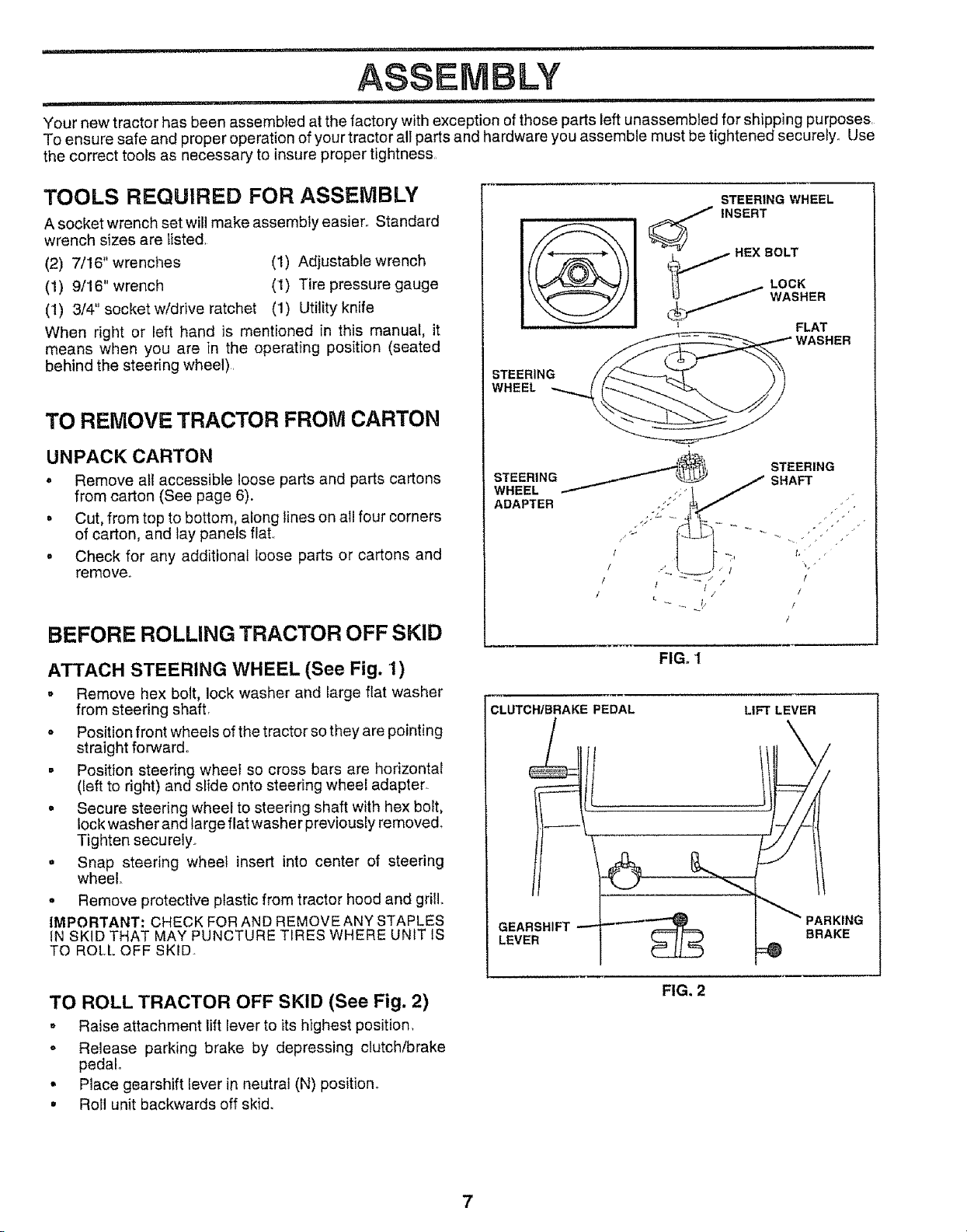
ATTACH STEERING WHEEL (See Fig. 1)
, Remove hex bolt, lock washer and large flat washer
from steering shaft.
• Position front wheels of the tractor sothey are pointing
straight forward.
• Position steering wheel so cross bars are horizontal
([eft to right) and slide onto steering wheel adapter_
o Secure steering wheel to steering shaft with hex bolt,
lock washer and large flat washer previously removed.
Tighten securely.
o Snap steering wheel insert into center of steering
wheel
, Remove protective plastic from tractor hood and grill..
IMPORTANT: CHECK FOR AND REMOVE ANY STAPLES
iN SKiD THAT MAY PUNCTURE TIRES WHERE UNiT IS
TO ROLL OFF SKID
STEERING WHEEL
'_ INSERT
STEERING __1__ -'_
STEERING
WHEEL
STEERING __
ADAPTER t . :S ;_:."_
I /
SHAFT
FIG. 1
CLUTCH/BRAKE PEDAL
GEARSHIFT
LEVER
LIFT LEVER
FLAT
WASHER
•/i
t, ¸ ,
!
/
!
/
TO ROLL TRACTOR OFF SKID (See Fig. 2)
o Raise attachment lift lever to its highest position.
• Release parking brake by depressing clutch/brake
pedal..
• Place gearshift lever in neutral (N) position°
= Roll unit backwards off skid.
FIG, 2

PREPARE BATTERY (See Fig. 3)
....... =
CAUTION: Wear eye and face shield.
Wash hands or clothing immediately if
accidentally in contact with batteryacid.
Do not smoke. Fumes from charged
battery acid are explosive.
Read the instructions included with the
battery vent caps. Alwayswear gloves,
clothing and goggles to protect your
hands, skin and eyes.
,11, i, i ii iiii,
Your unit has a battery charging system which issufficient
for normal use. However, periodic charging of the battery
with an automotive charger will extend its life.
. See instructions packed with vent caps in parts bag.
- Fill battery with acid. Fitl each cell until it reaches the
bottom of the vent wells° Do not overfill
• Allow battery to stand and settle for at least thirty
minutes After standing, check the battery cell acid
level, if below the vent wells, add more acid until the
correct level is reached°
While battery is standing (after adding acid) and later, while
battery is being charged, continue with assembly of unit.
IMPORTANT: TO MAXIMIZE THE LIFE OF YOUR
BATTERY, IT IS NECESSARY THAT THE BATTERY BE
CHARGED BEFORE USE FAILURE TO CHARGE
BATTERY CAN RESULT IN A SHORTENED BATTERY
LIFE.
- Charge battery at a rate of 6 amperes for' 1 hour. Use
a 12 volt battery charger. Observe all safety precau-
tions required for battery charging°
• Check the acid level after the battery is charged, If the
acid has fallen below the correct level, add distilled or
iron free water,
° Install the vent caps to cover the vent wells. Wash the
top of the battery with water' to remove any acid, then
wipe dry,
o Check battery case for leakage to make sure that no
damage has occurred in handling
• Dispose of excess battery acid. Neutralize acid for
disposal by adding it to two gallons of water in a five
gallon plastic container. Stir' with a wooden or plastic
paddle while adding baking soda until the addition of
more soda causes no more foaming.
• Follow instructions on how to install battery,
INSTALL SEAT (See Fig. 4)
Adjust seat before tightening adjustment knob.
o Remove cardboard packing on seat pan,
o Place seat on seat pan and assemble shoulder bolt.
. Assemble adjustment knob and flat washer loosely,
Do not tighten°
° Tighten shoulder' bolt securely°
• Lower seat into operating position and sit on seat.
o Slide seat until a comfortable position is reached which
allows you to press clutch/brake pedal all the way
down.
= Get off seat without moving its adjusted position_
= Raise seat and tighten adjustment knob securely.
FIG, 4
CHECK TIRE PRESSURE
The tires on your unit were overinflated at the factory for
shipping purposes° Correct tire pressure is important for
best cutting performance,
o Reduce tire pressure to PSI shown in "PRODUCT
SPECIFICATIONS" on page 3 of this manual.
CHECK BRAKE SYSTEM
After you learn 5ow to operate your tractor, check to see
that the brake is properly adjusted_ See "TO ADJUST
BRAKE" in the Service and Adjustments section of this
manual
CUT AWAY VIEW y VENTCAP
WELL
BATTERY
CELL ACID
LEVEL
FIG. 3
8
_11,= ,,Ji
ASSEMBLY
iii i,.11,,.11, ,i,i, i..................................... i i, ,
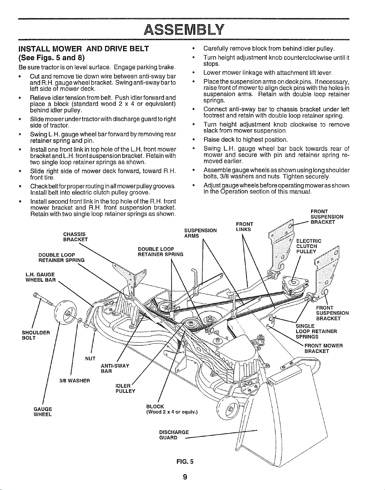
INSTALL MOWER AND DRIVE BELT
(See Figs. 5 and 8)
Be sure tractor ison level surface, Engage parking brake
o Cut and remove tie down wire between anti-sway bar
and R.H gauge wheel bracket. Swing anti-sway barto
left side of mower deck,,
. Relieve idler tension from belt. Push idler forward and
place a block (standard wood 2 x 4 or equivalent)
behind idler pulley°
o Slide mower under tractor with discharge guard to right
side of tractor.
o Swing L,Hogauge wheel bar forward by removing rear
retainer spring and pin°
• Install one front link in top hole of the L.H. front mower
bracket and LHo front suspension bracket, Retain with
two single loop retainer springs as shown°
,, Slide right side of mower deck forward, toward R.H.
front tire,
o Checkbelt for proper routing inall mowerpulleygrooves,
Install belt into electric clutch pulley groove.
. Install second front link inthe top hole of the RH front
mower bracket and R.H front suspension bracket°
Retain with two single loop retainer springs as shown,
CHASSIS
BRACKET
DOUBLE LOOP
DOUBLE LOOP
RETAINER SPRING
RETAINER SPRING
• Carefully remove block from behind idler pulley,,
• Turn height adjustment knob counterclockwise until it
stops,
o Lower mower linkage with attachment lift lever°
- Place the suspension arms on deck pins,, tf necessary,
raise front of mower to align deck pins with the holes in
suspension arms,. Retain with double loop retainer
springs,,
o Connect anti-sway bar to chassis bracket under left
footrest and retain with double loop retainer spring,
° Turn height adjustment knob clockwise to remove
slack from mower suspension.
° Raise deck to highest position,
• Swing Loll. gauge wheei bar back towards rear of
mower and secure with pin and retainer spring re-
moved eadier.
. Assemble gauge wheets as shown using long shoulder
bolts, 3/8 washers and nuts, Tighten securely.,
. Adjust gauge wheels before operating mower asshown
in the Operation section of this manual.
FRONT
SUSPENSION
BRACKET
ELECTRIC
CLUTCH
PULLEY
SUSPENSION
ARMS
FRONT
LINKS
LH. GAUGE
WHEEL BAR
SHOULDER
BOLT
GAUGE
WHEEL
FRONT
SUSPENSION
BRACKET
SINGLE
LOOP RETAINER
SPRINGS
MOWER
BRACKET
NUT
ANTI-SWAY
BAR
318WASHER
IDLER
PULLEY
BLOCK
(Wood 2 x 4 or equiv,)
DISCHARGE
GUARD
9
 Loading...