

Craftsman 917255980 Owner’s Manual

MODEL MBE 917=255980 OWNER'S MANUAL
®
oAssembly
oOperation
Customer
Responsibilities
Service
®Adjustments
• Repair Parts
Caution:
, Read and Follow
; all Safety Rules
and Instructions
, Before Operating
This Equipment

Safe Operation Practices for Ride-On Mowers
i
I PORTANT: THIS CUTTING MACHINE IS CAPABLE OF AMPUTATING HANDS AND FEETAND THROWING OBJECTS.
F
AILURETO OBSERVE THE FOLLOWING SAFETY INSTRUCTIONS COULD RESULT IN SERIOUS INJURY OR DEATH,
I. GENERAL OPERATION -
• Read, understand, and follow all instructionsinthe manual
and on the machine before starting.
• Only allow responsible adults, who are familiar with the
instructions, to operate the machine.
, Clear' the area of objects such as rocks, toys, wire, etc..,
which could be picked up and thrown by the blade_
• Be surethearea is clear of otherpeople before mowing. Stop
machine if anyone enters the area.
° Never carry passengers°
° Do notmow in reverse unless absolutely necessary. Always
look down and behind before and while backing.
° Be aware of the mower discharge direction and do not point
it at anyone. Do not operate the mower without either the
entire grass catcher or the guard in place.
° Slow down before tuming.
° Never leave a running machine unattended, Always turn off
blades, set parking brake, stop engine and remove keys
before d smountingo
° Turn off blades when not mowing.
• Stop engine before removing grass catcher or unclogging
chute.
• Mow only in daylight or good artificial light°
• Do not operate the machine while under the influence of
alcohol or drugs.
° Watch for traffic when operating near or crossing roadways.
• Use extra care when loading or unloading the machine tnto
a trailer or"truck._
II. SLOPE OPERATION
Slopesare a majorfactor related to loss-of-controlandtipover
accidents,whichcanresultin severeinjuryordeath. All slopes
requireextracaution.Ifyoucannotbackuptheslopeorifyoufeel
uneasyonit,donotmowiL
DO:
• Mowupand downslopes,notacross.
• Removeobstaclessuchas rocks,treelimbs,etc.
° Watch for holes, ruts, or bumps. Uneventerraincould
overturnthemachine° Tallgrasscanhideobstac/es
• Useslow speed..Choosea!owgearsothatyouwillnothave
tostoporshiftwhileontheslope.
° Follow the manufacturer's recommendations for wheel
weightsorcounterweightstoimprovestability.
° Use extracarewithgrasscatchersorotherattachments..
Thesecanchangethestabilityofthemachlne_
• Keepallmovementontheslopess/owand gradual Donot
makesuddenChangesin speedordirection_
o Avoid startingorstoppingona slope. If tireslosetraction,
disengagethe bladesandproceedslowlystraightdownthe
slope°
DONOT:
• _ Donottumonslopesuniessnecessary,andthen,tumslowty
andgraduallydownhill,ifpossible.....
SAFETY RULES &
IlL CHILDREN
Tragic accidents can occur' if the operator is not alert to the
presence ofchildren, Children are often attracted tothe machine
and the mowing activity. Neverassume that childrenwill remain,
where you last saw them_
• Keepchildrenout ofthe mowing area and under thewatchful
care of another responsible adulL
° Be alert and turn machine off if children enter the area.
o Before and when backing, look behind and down for small
children_
° Never catty children. They may fall off and be seriously
injured or interfere with safe machine operation.
• "Never allow chi[drento operate the machine.
• Use extra care when approaching blind comers, shrubs,
trees, or other objects that may obscure vision..
IV, SERVICE
• Use extra care in handling gasoline and otherfuels They are
flammable and vapors are explosive.
Use only an approved container_
Never remove gas cap or add fuel with the engine
running. Aliow engine [o cool before refueling_ Do not
smoke.
Never refuel the machine indoors.
Never store the machine or fuel container inside where
there is an open flame, such as a watr:r h ater.
• Never run a machine inside a closed area
° Keep nuts and bolts, especially blade attachment bolts, tight
and keep equipment in good condition.
° Never' tamper' with safety devtces_ Check their proper
operation regularly,
• Keep machine free ofgrass leaves, orotherdebds build-up,
C ean o t or fuel spillage° Allow machine to cool before
storing.
= Stop and inspect the equipment if you stdke an object.
Repair, if necessary, before restarting.
° Never make adjustments or repairs with the engine running.
• Grass catchercomponents are subject towear', damage, and
deterioration, which could expose moving parts or allow
objects to be thrown. Frequently check components and
replace with manufacturer's recommended parts, when nec-
essary_
° Mower blades are sharp and can cut. Wrap the blade(s) or
wear gloves, and use extra caution when servicing them°
• Check brake operation frequently_ Adjust and service as
required_
ii i i i ,,,,,,,,,,,,, ,,,,,, ,,_,,_,,,_,,,
j _ Lookfor this symbol to point out impor- I
J AA, tant safety precautions. It means J
J _ CAUTIONII! BECOME ALERTIII YOUR J
J _ SAFETY IS INVOLVED
....................................." .........
° Donotmownear'drop-offs,ditches,orembankments.The
mowercouldsuddenlyturnoverifa wheelisovertheedge
ofa clifforditch,orifanedgecavesin.
° Do not mow on wet grass_Reducedtractioncouldcause
sliding°
° Donottrytostabilizethemachinebyputtingyourfootonthe
ground,
CAUTION: Always disconnect spark
contact spark plug In order to prevent
plug wire and place wire where it cannot
accidental starting when setting up,
transporting, adjusting or making
repairs.
° Donot usegrasscatcheron steep slopes,,
2
iLllll

CONGRATULATIONS on your purchase of a Sears
Tractor. It has been designed, engineered and manufac-
tured to give you the best possible dependability and
performance,
Should you experience any problem you cannot easily
remedy, please contact your nearest Sears Authorized
Service CenteriDepartmento We have competent, we!_-
trained technicians and the proper tools to service or repair
this unit.
Please read and retain this manual, The instructions will
enable you to assemble and maintain your unit properly.
Always observe the "SAFETY RULES"°
MODEL
NUMBER 917°255980
SERIAL
NUMBER
DATE OF PURCHASE
THE MODELAND SERIAL NUMBERS WILL BEFOUND
ON A PLATE UNDER THE SEAT.
YOU SHOULD RECORD BOTH SERIAL NUMBER AND
DATE OF PLJRCHASE AND KEEP INA SAFE PLACE
FOR FUTURE REFERENCE
MAINTENANCE AGREEMENT
A Sears Maintenance Agreement is available on this prod-
uct., Contact your nearest Sears store for details.
CUSTOMER RESPONSIBILITIES
• Read and observe the safety rules..
. Followa regular schedule in maintaining, cadng for and
using your unit.
o Follow the instructions under"Customer Responsibili-
ties" and "Storage" sections of this owner's manual.
PRODUCT SPECiFiCATIONS
HORSEPOWER: 18_0
GASOLINE CAPACITY 3..5GALLONS
AND TYPE: UNLEADED REGULAR
OiL TYPE (API-SG): SAE 30 (above 32°F)
OIL CAPACITY: W! FILTER: 4.,0 PINTS
SPARK PLUG:
(GAP: ..025")
VALVE CLEARANCE: INTAKE: °003" - °006"
GROUND SPEED (MPH): Forward
TRANSAXLE OIL 4 QUARTS
CAPACITY AND TYPE: SAE 30 API*SG
TIRE PRESSURE: FRONT: 14 PSI
CHARGING SYSTEM: 3 AMPS BATTERY
BLADE BOLTTORQUE: 30-35 FT,.LBS,.
WARNING: This unit isequipped with an inL_rnalcombus*
tion engine and should not be used on or near any unim-
proved forest-covered, brush-covered or grass-covered
land unless the engine's exhaust system is equipped with
a spark arrester meeting applicable local or state laws (if
any),. If a spark arrester is used, it should be maintained in
effective working order by the operator_
in the state of California the above is required by law
(Section 4442 of the California Public Resources Code).
Other states mayhave similar laws, Federal laws apply on
federal lands.. A spark arrester for the muffler is available
through your nearest Sears Authorized Service Center/
Department (See R EPAIR PARTS section of this manual).
SAE 5W-30 (below 32°F)
W/O FILTER: 35 PINTS
CHAMPION RV15YC
EXHAUST: ,.016" - o019"
1st 0.75
2nd 1.50
3rd 250
4th 1.50
5th 3,5O
6th 5.75
Reverse 2,.25
REAR: 10 PSi
15 AMPS HEADLIGHTS
LIMITED TWO YEAR WARRANTY ON ELECTRIC START RIDING EQUIPMENT
For two (2) years from the date of purchase, if this riding equipment is maintained, lubricated and tuned up according to the
instructions in the owner's manual, Sears will repair or replace, free of charge, any parts found to be defective in material or
workmanship.
This Warranty does not cover:
• Expendable items which become worn during norma! use,such as blades, spark plugs, air cleaners and belts.
• Tire replacement or repair caused by punctures from outside objects, such as nails, thorns, stumps, or glass,
° Repairs necessary because of operator abuse, negligence, improperstorage or accident or the failure to maintain the
equipment according to the instructions contained in the owner's manual.
• Riding equipment used for commercial or rental purposes,
LIMITED 90 DAY WARRANTY ON BATTERY
For ninety (90) days from date of purchase, if anY battery included with this riding equipment proves defective in materi!l or
workmanship and our testing determines the battery will not hold a charge, Sears will replace the battery at no charge..
WARRANTY SERVICE IS AVAILABLE BY RETURNING THE RIDING EQUIPMENT TO THE NEAREST SEARS SERVICE
CENTER/DEPARTMENT IN THE UNITED STATES.
This Warranty gives you specific legal rights, and you may also have ether rights which may vary from state to state_
..... SEARS, ROEBUCK AND CO., 9/817 WA, HOFFMAN ESTATES, ILLINOIS 60179
3

TABLE OF CONTENTS
SAFETY RULES ............................................................ 2
PRODUCT SPECIFICATIONS ...................................... 3
CUSTOMER RESPONSIBILITIES ..................... 3, 16-18 ,_,
WARRANTY ...................... ;,........... (. .................. _,.......... 3 "_'
TRACTOR ACCESSORIES .......................................... 5
ASSEMBLY .............................................................. 7-10
OPERATION .......................................................... 11-14
INDEX
A
Accessories .............................................................5
Adjustments:
Brake ................................................2t
Carburetor ........................................25
Gauge Wheels ...............................13
Mower'
Front-To-Back ................................20
Side-To-Side ..................................19
Throttle Control Cable ........................25
Air Filter, Engine........................................18
Air Screen, Engine ......................................18
Assembly ..........................................................7-t0
B
Battery:
Charging ................................................8
Cleaning ..........................................................18
installation..................................................i0
Levels................................................8,16
Preparation ....................................8
Starting with Weak Battery ........... 23
Storage ......................................................26
Terminals ..............................................16
Belt:
Motion Drive
Removal/Replacement ..................22
Mower Drive
RemovallReplacement ............ 20
Mower Blade Drive
Removal/Replacement ...................21
Blade:
Sharpening ............................................16
Replacement .......................................16
Brake Adjustment .........................................2t
C
CarburatorAdjustment ..........................25
Controls, Tractor. .......................................11
Customer Responsibilities .................16-18
Engine:
AirFilter........................................18
Air Screen ............................................18
Cooling Fins .................................18
EngineOil................................13,i8
Fuel Filter .........................................18
Spark Plug(s) ..................................18
Tractor:
Battery.............................................16
Blade .............................................16
LubricationChart ..........................17
Maintenance Schedule ......................15
Tire Care ........................... 8,16,23
Transaxie .......................................17
Cutting Height, Mower ..............................12
Electrical:
Intedocks and Relays .................... 23
Schematic ....................................................30
WiringDiagram ...................................32
Engine:
Air Filter .........................................18
Air Screen .....................i.........................18
Cooling Fins .............................................18
Otl Change .....................................................17
Oil Level ...............................................17
Oil Type ........................................13,17
Preparation ..........................................13
Repair Parts ...........................................48-57
Starting ......................................................14
Storage .........................................26
Filter:
Air' Filter ........................................18
Fuel .................................................................18
Oil.........................................................18
Fuel:
Storage .......................................................26
Type .................................................13
Fuse .......................................................23
Headlights ..........................................................23
Hood Removal/Installation ........................24
Leveling Mower Deck ..................................19
Lubrication:
Chart .....................................................................t5
Engine.............................................17
Maintenance Schedule .............................15
Mower:
Adjustment, Front-to-Back ........... 20
Adjustment, Side-to-Side ..................19
Blade Replacement ................................21
BladeSharpening.........................16
Cutting Height .............................. 12
Installation...........................................19
Operation ..................................................13
Removal.............................................19
Mowing Tips ......................._._'._::_...............14
Muffter_................................._._...........................18
Spark Arrester .................................3,40
Oil:
Cold Weather Conditions ........ I3,17
Engine ..................................................17
Storage ...................................................26
MAINTENANCE SCHEDULE ...................................... 15
SERVICE AND ADJUSTMENTS ............................ 19-25
STORAGE ................................................................... 26
TROUBLESHOOTING ........................................... 27-28
REPAIR PARTS - TRACTOR ................................ 31-47
REPAIR PARTS - ENGINE .................................... 48-57
PARTS ORDERING/SERVICE ................ BACK COVER
E
Operation........................................11-14
OperatingMower ..................................13
Options:
Accessories ....................................................5
Spark Arrester ..................................3,40
P
ParkingBrake ................................11-12
PartsBag .........................................................................6
Parts, Replacement/Repair ................31-47
Product Specifications .........................................3
R
Repair Parts ........................................................31-47
F
Safety Rules .............................................................2
Seat ........................................................................... 8
Service and Adjustments .........................19-25
Carburetor....................i'....................25
Fuse .....................................................23
Hood Removaltlnstallation ...........24
Motion Drive Belt
Removal/Replacement ...............22
Mower Drive Belt
H
L
M
RemovaltReplacement ............ 20
Mower Blade Drive Belt
RemovaltReplacement .............21
MowerAdjustment .,
Front-to-Back .............................20
Side-to-Side ..................................t9
Mower Removal/Installation ......... 19
Tire Care ...............................8,15,23
Slope Guide Sheet .......................................... 59
SparkPlug(s)..............................................18
Specifications ...........................................3
StartingtileEngine .........................13-14
Steering Wheel ..................................................7,22
Stopping the Tractor ...............................12
Storage .........................................................26
S
T
Throttle Control Cable Adjustment .......25
Tires...................................................8,i6,23
Troubleshooting Chart ..................... 28-29
Transaxle .......................................................17
W
Warranty ......................................................3
0
Wtdng Diagram .........................................32
Wiring Schematic ......................................30
4

AN ATTACH
i1,,11,11,,i , i, i _ , ,_ r_r,,_rllll ............................... _ _:7'::11 i1_ [I i,'11 i'1,'11,1'
These accessories andattachments were available through most Sears retailoutlets and service centers when the tractor was purchased°
Most Sears stores can order these itemsfor you when you provide the model number of your tractor_
ENGINE
SPARK PLUG GAS CAN ENGINE OIL
FUELSTABILIZER
MAINTENANCE
BLADES BELTS
PERFORMANCE
Sears offers a wide variety of attachments that fit yourtractor° Many of these are listed below with brief explanations of how they can help
you. This list was current at thetime of publication;however, itmay change infuture years- more attachments may be added, changes
may be made inthese attachments, or some may no longer be available or fit your model. Contact your nearest Sears store for the
accessories and attachments that are available for your tractor.
Most of these attachments do not require additional hitches or conversion kits (thosethat do are indicated) and are designed for easy
attaching and detaching°
AERATOR promotes deep root growth for a healthy lawn. Ta-
pered 2.5-inch steel spikes mounted on 10-inch diameter discs
puncture holes in soil at close Intervals to let moisture soak in.
Steel weight tray for increased penetration°
BAGGER lets you collect grass clippings and leaves for a
healthier, neater looking lawn. Two Permanex containers hold
30_gallon plastic bags.
BUMPER protects front end of tractor from damage.
CARTS make hauling easy. Variety of sizes available, plus
accessories such as side panel kits, tool caddy, cart cover,
protective mat and dolly
CORING AERATOR takes small plugs out of soil to allow mois-
ture and nutrients to reach grass roots. 36-inch swath 24
hardened steel coring tips. 150 Ib capacity weight tray.
EASY OIL DRAIN VALVE makes oil changes easier, faster.
FRONT NOSE ROLLER cantersin front of mower deckto reduce
chances of "scalping" on uneven terrain.
GANG HITCH lets you tow 2 or3 pull-behind attachments at once,
such as sweepers, dethatchers, aerators (not for usewith rollers,
carts or other heavy attachments).
GAUGE WHEELS on both sides of the mower deck reduce
chances of "scalping" on uneven terrain. For mower decks not so
equipped.
MULCH RAKE/DETHATOHER loosens soil and flips thatch and
matted leaves to lawn surface for easy pickup. Twenty spring tine
teeth. Usefultoprepare bareareasforseeding. Available forfront
or rear mounting. HIGH PERFORMANCE REEL-ACTION
SPRING TINE DETHATCHER covers 36-inch wide path and
tosses thatch into large hopper. Mounts behind tractor.
MULCHING KIT, once installed, lets you mulch, discharge orbag
clippings (bagger optional) without changing blades. For models
not equipped as 3-in-1 Convertible mowers.
RAMP TOPS AND FEET let you load and unload tractor from a
pickup truck. Use with 2 x 8 or2 x 10 lumber°
ROLLER for smoother lawn surface. 36-inch wide, 18-inct_
diameterwater-tlght drum holds upto 390 Ibs ofweighL Rounded
edges prevent harm to turf. Adjustable scraper automatically
cleans drum,
SNOW BLADE for snow removalonly. 14-inch hlgh,42-inch wide
blade clears 38-inch path when angled leftor right.. Raises, bowers
with side lever. Adjustable skids; replaceable, reversible scraper
bar. (Use with tire chains and wheel weights and/or reardrawbar
weight..)
SNOWTHROWER has 40-inch swath. Drum-type augerhandles
powdery and wet/heavy snow. Mounts easily with simple pin
arrangemenL Discharge chute adjusts from tractor seat. 6-Inch
diameter spout discharges snow 10 to 50 feet° Lift controlled at
tractor seat. (Use with chains and wheel weights and/or rear
drawbarweighL)
SPRAYERS use 12wolt DC electric motor that connects to the
tractor battery or other 12-volt source_ includes booms for
automatic spraying and hand held wand forspot spraying. Wand
has adjustable spray pattern° For applying herbicides, insecti-
cides, fungicides and tiquidfertilizers, '
SPREADER/SEEDERS make seeding, fertilizing, and weed kill-
ing easy. Broadcast spreaders are also usefulfor granular de-
icersand sand.
SWEEPERS let you collect grass clippings and leaves°
TILLER cultivates and prepares soil Inone operation° Uses PTO
from tractor; 12 counter-rotating blades.. Breaks ground with
upper-cut action, then deflects and retills itinto a soft, aerated soil.
Chain-drive transmission. Tills 2t-Inch path, 6-inches deep_ (Use
chains and wheel weightso)
TILLER has 8 hp engine to prepare seed beds, cultivate, and
compost garden restdue_ Chaimdrive transmission. Six 1l-inch
diameter one piece heat-treated steel tines. Tills 30-1nch path°
(Requires sleeve hitch°) Or use 5 hp tow-behind TILLER with
36-inch swath to prepare seed beds, cultivate and compost
garden residue. Tiller has its own built-in lift and depth control
system and does NOT require a sleeve hitch° Fits any lawn,yard
or garden tractor. Simply hook up to the tractor drawbar andgol
Optional accessories for 5 hp tiller convert unit for dethatching,
aerating, hilling...without toots
TIRE CHAINS are heavy duty; closely spaced extra-large cross
linksgive smooth fide, outstanding traction°
TRACTOR CAB has heavy duty vinyl fabric over tubular steel
frame, ABS plastic top; clear plastic windshield offers 360 degree
visibility. Hinged metal doors with catch. Keeps operatorwarm
and dry° Remove vinyl sides and windshields for use as sun
protector in summer. Optional accessories include: tinted/
tempered solid safety glass windshield with hand operated wiper;
12-volt amber caution light for mounting on cab top.
VACSforpowerfulcollection ofheavy grass clippings and leaves.
Optional wand attachment to pick up debris in hard-to-reach
places. VAC/CHIPPER includes a chipper-shredder_
WEIGHT BRACKET for drawbar for snow removal applications.
Uses (1) 55 ib_ weight.
WHEEL WEIGHTS for rear wheels provide needed traction for
snow removal or dozing heavy materials.
5
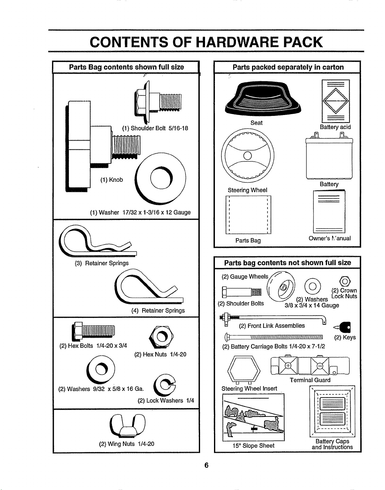
OF HARDWARE PACK
III I I I I J L Jlllll'lllll
Parts Bag contents shown full size
Parts packed separately in carton
(1) Shoulder Bolt 5/!6-18
(1) Knob
(1) W'asher 17132x 1-3/16 x 12 Gauge
(3) Retainer Springs
(4) Retainer Springs
Seat
Steering Wheel
PartsBag
Parts bag contents not shown full size
12/Gauge VVheelsi__
Battery acid
l I
Battery
uL, iL : :_::=_
Owner's rianual
©
}::::] "_l_] _( (u._j/j (2) Crown
._. _ ..... _ (2) Washers Lock Nuts
{z__noutaer _ol[s 3t8 x 3/4 x 14 Gauge
I_llllftlttllllllltlllll!l!U@
(2) Hex Bolts 1/4-20 x 3/4
(2) Hex Nuts 1/4-20
(2) Washers 9/32 x 5/8 x 16 Ga.
(2) Lock Washers 1/4
(2) Wing Nuts 1/4-20
t lu,lllull,
"_ i2_Fro.,L'."Aosomb"eo
(2) Battery Carriage Bolts 1/4-20 x 7..112
Termfnal Guard
Steering Wheel Insert
15° Slope Sheet
6
(2) Keys
, _
,,, , ,
['
Battery caps
and Instructions

BLY
Your new tractor has been assembled at the factory with exception of those parts left unassembled for shipping purposes.
To ensure safe and proper operation of your tractor all parts and hardware you assemble must be tightened securely. Use
the correct tools as necessary to insure proper tightness.
t.
TOOLS REQUIRED FOR ASSEMBLY
A socket wrench set will make assembly easier, Standard
wrench sizes are listed°
(2) 7/16" wrenches (1) Tire pressure gauge
(1) 9/16" wrench (1) Utility knife
(1) Adjustable wrench
When right or left hand is mentioned in this manual, it
means when you are in the operating position (seated
behind the steering wheel).
TO REMOVE TRACTOR FROM CARTON
UNPACK CARTON
° Remove all accessible loose parts and parts cartons
from carton (See page 6).
o Cut, from top to bottom, along lines on all four corners
of carton, and lay panels fiat.
° Check for any additional loose parts or cartons and
remove.
BEFORE ROLLING TRACTOR OFF SKID
ATTACH STEERING WHEEL (See Fig. 1)
° Remove hex bolt, lock washer and large flat washer
from steering shaft.
° Position front wheels of the tractor sothey are pointing
straight forward,
° Position steering wheel so cross bars are horizontal
(left to right) and slide onto steering wheel adapter°
o Secure steering wheel to steering shaft with hex bolt,
lock washer and large fiat washer previously removed.
Tighten securely,
= Snap steering wheel insert into center of steering
wheel.
= Remove protective plastic from tractor hood and grill.
IMPORTANT: CHECK FORAND REMOVE ANY STAPLES
IN SKID THAT MAY PUNCTURE TIRES WHERE UNIT IS
TO ROLL OFF SKID.
STEERING WHEEL
/ INSERT
_,_HEX BOLT
STEERING
WHEEL
ADAPTER
STEERING
SHAFT
/
FIG. 1
CLUTCHJBRAKE PEDAL LIFT LEVER
GEARSHIFT
LEVER
FLAT
/
/
PARKING
BRAKE
.
TO ROLL TRACTOR OFF SKID (See Fig. 2)
° Raise attachment liftlever to itshighestposition°
= Release parking brake by depressing clutch/brake
pedal°
° Place gearshift lever in neutral (N) position.
o Roll unit backwards off skid_
FIG. 2
7

ASSEMBLY
HOW TO SET UP YOUR TRACTOR
PREPARE BATTERY (See FJg._3)
I I' ii iij iiiiiii i ii IIII
CAUTION: Wear eye and face shield.
Wash hands or clothing immediately if
_ accidentally in contact with batlen]acid.
Your unit has a battery charging system which is sufficient
for normal use. However',periodicchargingof the battery
with an automotive charger will extend itslife.
• See instructionspacked withvent caps in partsbag.
° Fillbatter] with acid. Filteach cell until it reaches the
bottom of the vent wells. Do not overfill.
• Allow battery to stand and settle for at least thirty
minutes° After standing, check the battery cell acid
teveL If below the vent wells, add more acid until the
correct level is reached.
While battery isstanding (after adding acid) and later, while
battery is being charged, continue with assembly of unit.
IMPORTANT: TO MAXIMIZE THE LIFE OF YOUR
BATTERY, IT IS NECESSARY THAT THE BATTERY BE
CHARGED BEFORE USE. FAILURE TO CHARGE
BATTERY CAN RESULT IN A SHORTENED BATTERY
LIFE.
• Charge battery at a rateof 6 amperes for 1 hour. Use
a 12 volt battery charger'. Observe all safety precau-
tions required for battery charging°
° Check the acid level after the battery is charged. If the
acid has fallen below the correct level, add distilled or
iron free water°
° install the vent caps to cover the vent wells. Wash the
top of the battery with water to remove any acid, then
wipe dry_
• Check battery case for leakage to make sure that no
damage has occurred in handling..
• Dispose of excess battery acid. Neutralize acid for
disposal by adding it to two gallons of water in a five
gallon plastic container. Stir with a wooden or plastic
paddle while adding baking soda until the addition of
more soda causes no more foaming.
° Follow instructionson how to installbattery.
Do not smoke. Fumes from charged
battery acid are explosive.
Read the instructions included withthe
battery vent caps. Always wear gloves,
clothing and goggles to protect your
hands, skin and eyes.
INSTALL SEAT (See Fig. 4)
Adjust seat before tightening adjustment knob_
° Remove cardboard packingon seat pan.
° Place seat on seat pan and assemble shoulder boll
• Assemble adjustment knob and fiat washer loosely.
Do not tighten.
° Tighten shoulder bolt securely.
° Lower seat into operating position and sit on seat.
° Slide seat until acomfortable position is reached which
allows you to press clutch/brake pedal all the way
down.
• Get off seat without moving its adjusted position.
° Raise seat and tighten adjustment knob securely.
SEAT
SEAT PAN
SHOULDER
BOLT
FLAT
ADJUSTMENT
KNOB
WASHER
FIG. 4
CHECK TIRE PRESSURE
The tires on your' unit were overinflated at the factoryfor
shippingpurposes. Correct tire pressure is Important for
best cuttingperformancm
° Reduce tire pressure to PSt shown in "PRODUCT
SPECIFICATIONS on page 3 of this manual.
CHECK BRAKE SYSTEM
After you [earn how to operate your' tractor',check to see
that the brake is properly adjusted° See "TO ADJUST
BRAKE" in the Service and Adjustments section of this
manual.
CUTAWAYVIEW
!
,.r._ VENT CAP
I
VENT WELL
BATTERY
CELL ACID
LEVEL
FIG. 3
8

INSTALL MOWER AND DRIVE BELT
(See Figs. 5and 8)
Besure tractor ison level surfacel Engage parking bra!_o
o Cut and remove tie down wire between anti-sway bar
and R.Hogauge wheel bracket.,Swing anti-sway barto
left side of mower deck,.
° Relieve idlertensionfrom belt, Pushidlerforward and
place a block (standard wood 2 x 4 or equivalent)
behind idler pulley.
o Slide mower undertractorwith dischargeguardto right
side oftractor°
= Swing LH. gauge wheel barforward byremoving rear
retainer spring and pin°
° Instalione front link intop hole of the L.H. front mower
bracketand L.H. front suspensionbracketoRetainwith
two single loop retainer springsas shown.
o Slide right side of mower deck forward, toward R.H.,
front tire,
= Checkbeltfor properroutinginallmowerpulleygrooves.,
install belt into eiectric clutch pulteygroove.
o lnstallsecond front linkinthe tophole ofthe R°H. front
mower bracket and R.Ho front suspension bracket.
Retain withtwo single loopretainer springsas shown,
CHASSIS
BRACKET
DOUBLE LOOP
DOUBLE LOOP
RETAINER SPRING
RETAINER SPRING
° Carefully remove block from behind idler puUey_
• Turn height adjustment knob counterclockwise until it
_stopso
o
Lower mower linkage with attachment lift lever.
o
' Place the suspension arms on deck pins. If necessary,
raise front ofmower to align deck pins with the holes tn
suspension arms,, Retain with double loop retainer
springs,,
• Connect anti-sway bar to chassis bracket under left
footrest and retain with double loop retainer spring.
• Turn height adjustment knob clockwise to remove
slack from mower suspension_
o Raise deck to highest position°
• Swing Loll, gauge wheel bar back towards rear of
mower and secure with pin and retainer spring re-
moved earlier.
° Assemble gaugewheels asshown using tongshoulder
bolts, 3/8 washers and nuts. Tighten securely.
° Adjust gaugewheels before operating mower as shown
in the Operation section of this manual,.
FRONT
SUSPENSION
BRACKET
ELECTRIC
CLUTCH
PULLEY
SUSPENSION
ARMS
FRONT
LINKS
LH. GAUGE
WHEEL BAR
SHOULDER
BOLT
GAUGE
WHEEL
3_ WASHER
NUT
ANTI-SWAY
BAR
IDLER
PULLEY
BLOCK
(Wood 2 x 4 or equivo)
DISCHARGE
GUARD
FIG. 5
FRONT
SUSPENSION
BRACKET
SINGLE
LOOP RETAINER
_IGS
BRACKET
9
CHECK DECK LEVELNESS
Forbestcuttingresults,mower housingshouldbe properly_.
leveled_ See "TO LEVEL MOWER HOUSING" in the_,
Service and Adjustments section of t his manual
CHECK FOR PROPER POSITION OF ALL
BELTS
See the figuresthat are shown for replacing motion, mower
drive, and mower blade drive belts in the Service and
Adjustments section of this manual, Verify that the belts are
routed correcUy.
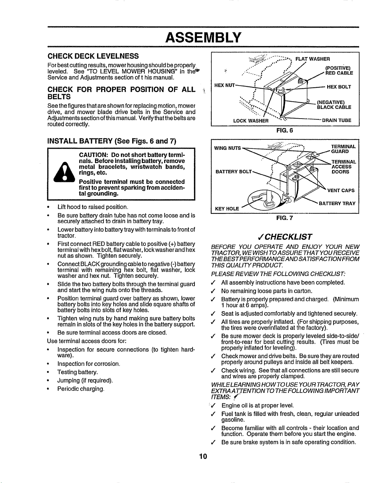
INSTALL BATrERY (See Figs. 6 and 7)
CAUTION: Do not short battery termi-
nals. Before installing battery, remove
rings, etc.
metal bracelets, wristwatch bands,
Positive terminal must be connected
first to prevent sparking from acciden-
tal grounding.
• Lifthood to raised position.
° Be sure batter_jdrain tube has not come loose and is
securely attached to drain in battery tray.
o Lower battery into batterytraywith terminals to front of
tractor.
° First connect RED battery cable to positive (+) battery
terminal with hex bolt, flat washer, lock washer and hex
nut as showrL Tighten securely.
• Connect BLACK grounding (_bleto negative (-)battery
terminal with remaining hex bolt, flat washer, lock
washer and hex nut.. Tighten securely,,
° Slide the two battery bolts through the terminal guard
and start the wing nuts onto the threads.
o Position terminal guard over battery as shown, lower
battery bolts into key holes and slide square shafts of
batter7 bolts into slots of key holes.
° Tighten wing nuts by hand making sure battery bolts
remain inslots of the key holes inthe battery support.
° Be sure terminal access doors are closed°
Use terminal access doors for:
. Inspection for secure connections (to tighten hard*
ware).
• Inspection for corrosion°
• Testing battery_
, Jumping (if required),.
• Periodic charging°
BLY
HEX BOLT
(NEGATIVE)
BLACK CABLE
LOCK WASHER DRAIN TUBE
FIG. 6
FIG. 7
,/CHECKLIST
BEFORE YOU OPERATE AND ENJOY YOUR NEW
TRACTOR, WEWISH TOASSURE THAT YOU RECEIVE
THEBESTPERFORMANCEAND SATISFACTION FROM
THIS QUALITY PRODUCT.
PLEASE REVIEW THE FOLLOWING CHECKLIST:
,/ All assembly instructions have been completed°
,/ No remaining loose parts incarton.
,/ Battery isproperlyprepared and charged. (Minimum
1 hour at 6 amps).
,/ Seat is adjustedcomfortablyand tightened securely.
,/ All tires are properlyinflated. (Forshippingpurposes,
thetires were overinflated at the factory).
#" Be sure mower' deck is properly leveled side-to-side/
front-to-rear for' best cutting results. (Tires must be
properlyinflated for' leveling).
4" Check mower-anddrive belts. Be sure they are routed
properly around pulleys and inside all belt keepers..
#" Check wiring. See that all connections are still secure
and wires are properlycIamped.
WHILE LEARNING HOW TO USE YOUR TRACTOR, PAY
EXTRAA TTFEIVTIONTO THE FOLLOWING IMPORTANT
ITEMS: _"
::j
Engine oil is at proper level,
Fuel tank is filled with fresh, clean, regular unleaded
v'
gasoline.
Become familiar with all controls - their location and
function° Operate them before you start the engine.
Be sure brake system is in safe operating condition_
10
OPERATI
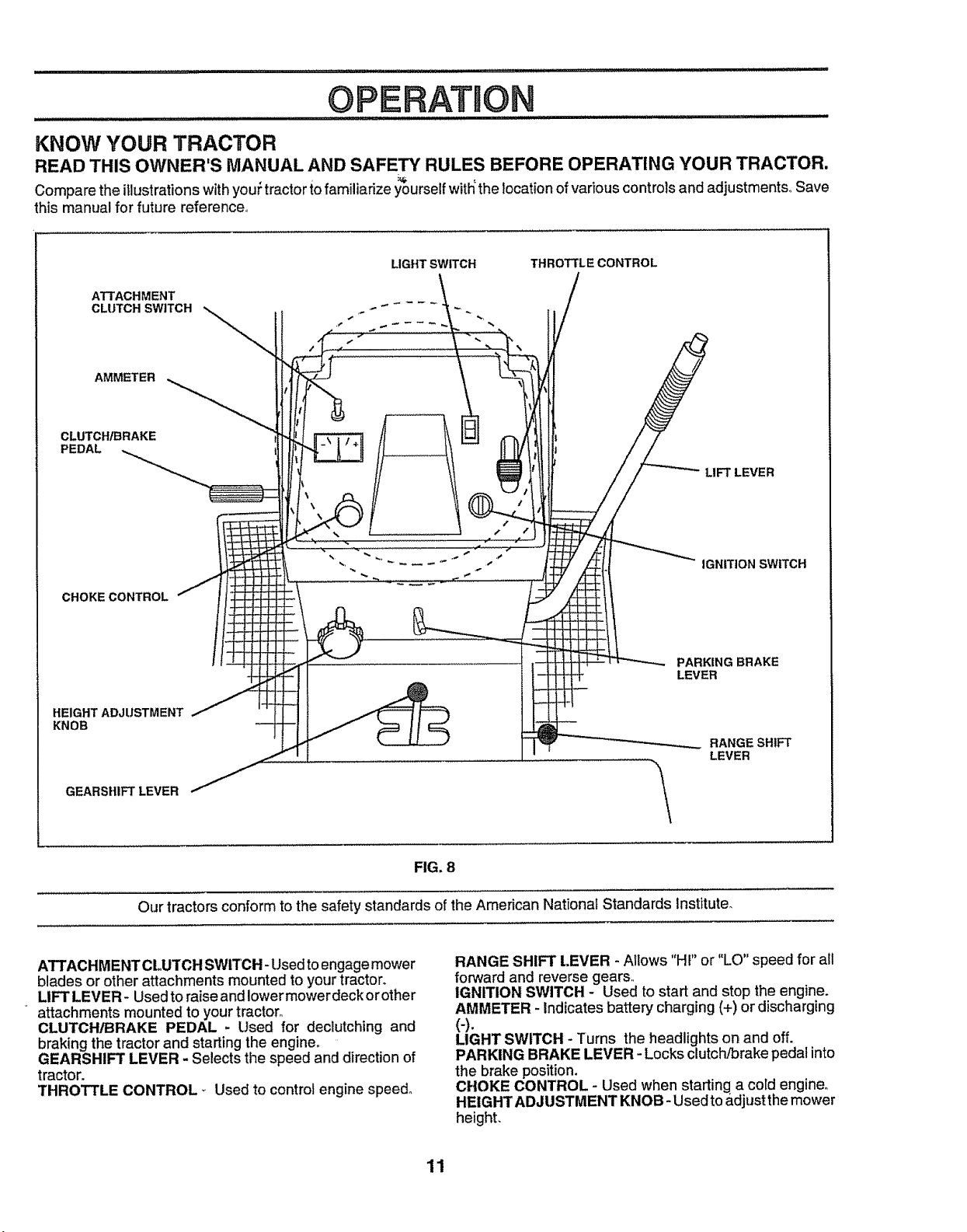
KNOW YOUR TRACTOR
READ THIS OWNER'S MANUAL AND SAFETY RULES BEFORE OPERATING YOUR TRACTOR.
Compare the illustrationswithyouPtractorto familiarize yourselfw_ththe locationofvariouscontrolsand adjustments° Save
this manual for future reference,,
ATTACHMENT
CLUTCH SWITCH
AMMETER
CLUTCH/BRAKE
PEDAL
CHOKE CONTROL
HE1GHTADJUSTMENT
KNOB
LIGHT SWITCH
THROTTLECONTROL
LIFT LEVER
IGNITION SWITCH
PARKING BRAKE
LEVER
RANGESHtFT
LEVER
GEARSHIFT LEVER
Our tractors conform to the safety standards of the American National Standards Institute_
ATTACHMENT CLUTCH SWITCH- Used toengage mower
blades orother attachments mountedto your tractor°
LIFT LEVER- Usedto raise and lowermower deck orother
attachments mounted to yourtractor_
CLUTCH/BRAKE PEDAL - Used for declutching and
braking the tractor and starting the engine°
GEARSHIFT LEVER - Selects the speed and direction of
tractor.
THROTTLE CONTROL _ Used to control engine speed.
FIG, 8
RANGE SHIFT t.EVER - Allows "HI" or "LO" speed for all
forward and reverse gears,,
IGNITION SWITCH - Used to start and stop the engine.
AMMETER - Indicates battery charging (+) or discharging
(-).
LIGHT SWITCH - Turns the headlights on and off.
PARKING BRAKE LEVER -Locks clutch/brake pedal into
the brake position.
CHOKE CONTROL - Used when starting a cold engine°
HEIGHT ADJUSTMENT KNOB- Usedto &djustthe mower
height.
11
The operation of any tractor can result in foreign objects thrown into the eyes, which can
result insevere eye damage, Always wear safety glasses or eye shields while operating your
tractor or pe_orminganyadjustme_s or repaizs. We recommend a wide vision safety mask
for over the spectacles or standard safety glasses,
HOW TO USE YOUR TRACTOR
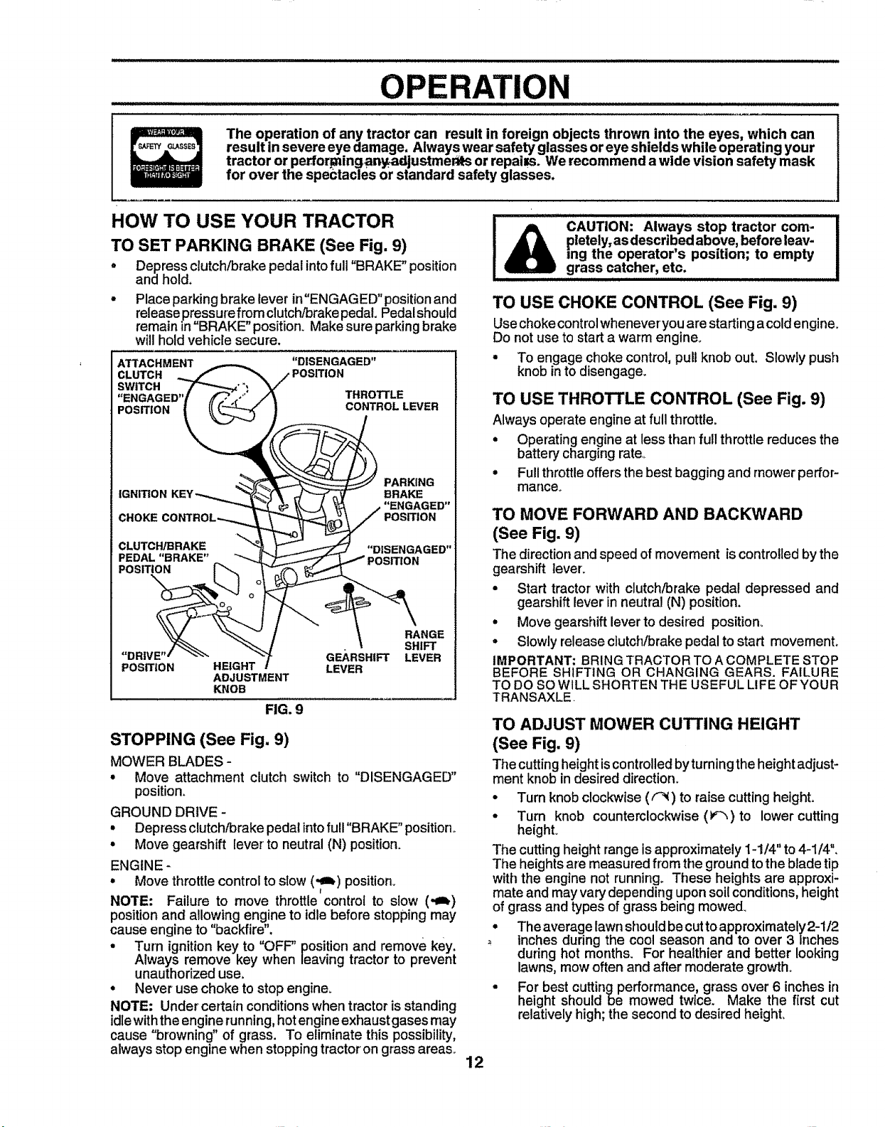
TO SET PARKING BRAKE (See Fig. 9)
• Depress clutch/brake pedal intofull"BRAKE" position
and hold.
• Place parkingbrake lever in"ENGAGED"position and
release pre,ssure from clutch/brake pedal. Pedalshould
remain in BRAKE position. Makesure parking brake
will hold vehicle secure.
ATTACHMENT "DISENGAGED"
CLUTCH POSITION
SWITCH
POSITION
IGNITION
CHOKE
CLUTCH/BRAKE
PEDAL "BRAKE"
POSITION r_
"DRIVE"' "<"_
POSITION
HEIGHT
ADJUSTMENT
KNOB
FIG. 9
STOPPING (See Fig. 9)
MOWER BLADES -
• Move attachment clutch switch to "DISENGAGED"
position,
GROUND DRIVE -
• Depress clutch/brake pedalinto fuII"BRAKE" position°
• Move gearshift lever to neutral (N) position.
ENGINE -
• Move throttIe control to sIow ('_) position.,
NOTE: Failure to move throttle control to slow (,_)
position and allowing engine to idle before stopping may
cause engine to "backfire",
• Turn ignition key to "OFF" position and remove key.
Always remove key when leaving tractor to prevent
unauthorized use,
• Never use choke to stop engine.
NOTE: Under certain conditions when tractor isstanding
idlewith the engine running,hotengine exhaust gases may
cause "browning" of grass. To eliminate this possibility,
always stop engine when stopping tractor on grass areas..
THROTTLE
CONTROL LEVER
_ PARKING
BRAKE
"ENGAGED"
POSITION
"DISENGAGED"
GEARSHIFT
LEVER
RANGE
SHIFT
LEVER
CAUTION: Always stop tractor com-
pletely, as described above, before leav-
ing the operator's position; to empty
grass catcher, etc.
TO USE CHOKE CONTROL (See Fig. 9)
Use choke control whenever you are starting acold engine_
Do not use to start a warm engine.
• To engage choke control, pullknob out. Slowly push
knob into disengage.
TO USE THROTTLE CONTROL (See Fig. 9)
Always operate engine at full throttle.
• Operating engine at less than full throttle reduces the
battery charging rate,_
• Full throttle offers the best bagging and mower perfor-
mance_
TO MOVE FORWARD AND BACKWARD
(See Fig, 9)
The direction and speed of movement is controlled by the
gearshift leven
• Start tractor with clutch/brake pedal depressed and
gearshift lever in neutral (N) position.
• Move gearshift lever to desired position_
• Slowly release clutch/brake pedal to start movement.
IMPORTANT; BRING TRACTOR TO A COMPLETE STOP
BEFORE SHIFTING OR CHANGING GEARS. FAILURE
TO DO SO WILL SHORTEN THE USEFUL LIFE OF YOUR
TRANSAXLE.
TO ADJUST MOWER CUTTING HEIGHT
(See Fig, 9)
The cutting height iscontrolled byturning the height adjust-
ment knob in desired direction.
• Turn knob clockwise (F_) to raise cutting height.
• Turn knob counterclockwise (_) to lower cutting
height.
The cutting height range is approximately 1-1/4" to 4-1/4".
The heights are measured from the ground to the blade tip
with the engine not running° These heights are approxi-
mate and may vary depending upon soil conditions, height
of grass and types of grass being mowed_
° Theaveragelawnshouldbecuttoapproximately2-1/2
inches during the cool season and to over 3 Inches
during hot months. For healthier and better looking
lawns, mow often and after moderate growth°
= For best cutting performance, grass over 6 inches in
height should be mowed twice. Make the first cut
relatively high; the second to desired heighL
12

OPERATION
TO ADJUST GAUGE WHEELS (See Fig. 10)
o Adjust mower to desired cutting height,
° Lower mower with lift control Removeo_ear retainer
spring and clevis pinwhich s_cure each gauge wheel,
• Lower gauge wheels to ground° Raise gauge wheels
slightly to align holes in bracket and gauge wheel bar,
and insert clevis pins, Gauge wheels should be slightly
off the ground°
° Replace retainer springs into clevis pins.
RETAINER
SPRING
CLEVIS
GAUGE
WHEEL BAR
GAUGE
WHEEL
BRACKET
FIG. 10
TO OPERATE MOWER (See Fig. 8 and 9)
Yourtractor isequippedwithan operatorpresencesensing
switch° Any attempt by the operator to leavethe seat with
the engine running and the attachment clutch engaged wifl
shut off the engine.
• Select desired height of cut,
o
Lower mower with attachment lift control
o
Start mower blades by engaging attachment dutch
control°
TO STOP MOWER BLADES -disengage attachment
clutch control°
without either the entire grass catcher,
I_ AUTION: Do not operate the mower
on mowers so equipped, or the dis-
charge guard in place.
\
_R.H.
RUNNER
TO OPERATE ON HILLS
I _& CAUTION: Do not drive up or down I
hills with slopes greater than 15° and I
do notdriveacros s any slope. ...... I
o
Choose the slowest speed before starting up or down
hitls.
o
Avoid stopping or changing speed on hillso
o
If slowing is necessary, move throttle control lever to
slower position.
o
If stopping is absolutely necessary, pushclutch/brake
pedal quickly to brake position and engage parking
brake.
Move gearshift lever to 1st gear and range shift lever to
low (L) position°Besure you have allowed room for unit
to roli slightly as you restart movement.
o
To restart movement, slowly release parking brake and
clutch/brake pedal,
o
Make all turns slowly.
TO TRANSPORT
o Raise attachment lift to highest position with attach-
ment lift control,
° When pushing or towing your tractor, be sure gearshift
lever isin neutral (N) position.
° Do not push or tow tractor at more than five (5) MPH°
NOTE: To protect hood from damage when transporting
your tractor on a truck or atrailer, besure hood isclosed and
secured to tractor, Use an appropriate means of tying hood
to tractor (rope, cord, etco)o
BEFORE STARTING THE ENGINE
CHECK ENGINE OIL LEVEL (See Fig. 12)
• The engine inyourtractor has been shipped, from the
factory, already filled with summer weight oil.
° Check engine oil with tractor on level ground.
° Remove oilfillcap/dipstickandwipe clean, reinsertthe
dipstick and pushitall the way down into thetube, wait
for a few seconds, remove and read oil level. If
necessary, add oil until "FULL" mark on dipstick is
reached. Do not overfill.
. For coldweather operationyou should change oilfor
easier starting (See OIL VISCOSITY CHART" inthe
Customer Responsibilitiessection of this manual).
° To change engine oil, see the Customer Responsibili-
ties section inthis manual,
ENGINE OIL
FILLER CAP/DIPSTICK
FIG. 11
DI,sCHARGE
GUARD
13 FIG. 12

ADD GASOLINE
• Fi!! fuel tank. Use fresh, clean, regular unleaded
gasoline. (Use of leaded gasolin._willi_q.cr_a,_ca_o_'-;
and lead oxide deposits and reduce v_a'lvelire)_ .....
IMPORTANT: WHEN OPERATING IN TEMPERATURES
BELOW 32°F(0°C), USE FRESH, CLEAN WINTER GRADE
GASOLINE TO HELP INSURE GOOD COLD WEATHER
STARTING_
WARNING: Experience indicates that alcohol blended
fuels (called gasohol or' using ethanol or methanol) can
attract moisture which leads to separation andformation of
acids during storage. Acidic gas can damage the fuel
system of an engine while in storage. To avoid engine
problems, the fuel system should be emptied before stor-
age of 30 days or longer. Drain the gas tank, start the
engine and let it run until the fuel lines and carburetor are
empty. Use fresh fuel next season. See Storage Instruc-
tions for' additional information. Never use engine or
carburetor' cleaner' products in the fuel tank or permanent
damage may occur.
fi!lerneck. Do notoverfili. Wipe offany
l& CAUTION: Fill to bottom of gas tank
spilled oil or fuel. Do not store, spill or
use gasoline near an open flame.
TO START ENGINE (See Fig. 9)
When starting engine for the first time or if engine has run
out of fuel, it willtake extracrankingtime to movefuel from
the tank tothe engine.
• Depress clutch!brake pedal and set parking brake_
° Place gearshift lever in neutral (N) position.
° Move attachment clutch to "DISENGAGED" position.
° Pull choke control out to choke (kl) positionfor cold
eng nestart° For warm engine start do not usectloke
contmL
• Move throttlecontrolto midway between fast (._) and
s!ow (,_) positions.
• insertkeyintoIgnitionand turnkeyclockwiseto"START"
positionand release key assoonas engine starts. Do
not run starter continuously for more than fifteen
seconds per rninute_ If engine does not start after
several attempts, move throttle control to fast (,f_)
position,wait a few minutes and try again.
• When engine starts, slowlypush choke control in.
• Move throttlecontrolto fast (_) position°
° Allow engine to warm up for a few minutes before
engaging drive orattachments..
NOTE: If at a highaltitude (above 3000 feet) or incold
temperatures (below 32°F), the carburetor'fuel mixture
may need to beadjusted for best engine performance. See
'q'O ADJUST CARBURETOR" in the Service and Adjust-
ments section of this manual
MOWING TIPS
° Tire chains cannot be used wilen the mower housing
is_attachedto tractor.
° Mower should be properly leveled for best mowing
p_rformance_ See"TO LEVEL MOWER HOUSING in
the Service and Adjustments section of this manual.
° Use the runner on the dght hand side of mower as a
guide. The blade cuts approximately an inch outside
the runner(See Fig..11)_
° The left hand side of mower should be used for trim-
ming.
° Drive so that clippings are discharged onto the area
that has been cut. Have the cut area to the right of the
tractor.. This will result.in a more even distribution of
clippings and more unif_xm cutting.
• When mowing large areas, start by turning to the right
so that clippings will discharge away from shrubs,
fences, driveways, etc, After one or'two rounds, mow
in tire opposite direction making left hand turns until
finished (See Fig_ 13).
• If grass is extremely tall, it should be mowed twice to
reduce load and possible fire hazard from dried clip-
pings. Make first cut relatively high; the second to the
desired heighL
• Do not mow grass when it is wet, Wet grass will plug
mower and leave undesirable clumps. Allow grass to
dry before mowing.
• Always operate engine at full throttle when mowing to
assure better' mowing performance and proper dis-
charge of material, Regulate ground speed by select-
ing a low enough gear' to give the mower cutting
performance as well as the quality of cut desired.
• When operating attacttments, select a ground speed
that will suit the terrain and give best performance of
the attachment being used.
,i(
FIG. 13
14
CUSTOP,!I
MAINTENANCE SCHEDULE /'__o _"_o__/
AS YOU COMPLETE _'__Z_.?,-_Z_og-_"
REGULAR SERV!C_E_..........................................__'_SERVICE DATES
CheckB keOporation " " !
CheckTire Pressure i6_ 6#4
CheckforLooseFasteners i_ 6#4
C LubricationChart 6#4 6#4
.Check.Batte.rYLevel/Recharge ................" ' _ __ ...................................
0 Clean BatteryandTerminals 6##'
R CheckTransaxleCooling 6_
Adjust BladeBelt(s)Tension ........................ 6#_'_ . I . ,
Adjust MotionDriveBelt(s)Tension $_s
CheckEngine OilLevel 6## 6#4
ChangeEngineOil 64_ 6#_'12,3 64#
E CleanAir Filter 6#_'2 ' " _................
N uCleanAir Screen ................. !#42
G inspectMuffler/SparkArrester 6#4................................
! ReplaceOil Filter (Ifequipped) _,2
........... : : : = : :
• . z ................. _ _ u i i = = , ,
c,oonEng!neooo,,oo .....
ReplaceSparkPlug ._ . 6_ .......
ReplaceAir Filter PaperCartridge If'2
Replace Fue,!,,Fitter ........................... _/ .....
1 - Change more often when operating under a heavy load or in high ambtent temperatures 3 * If equipped wilh oil filter, change oil eve_ 50 hours.
2.- Service more often when operaling tn dirty or dusty condtltons. 4 - Replace blades more elten when mowing in sandy sell
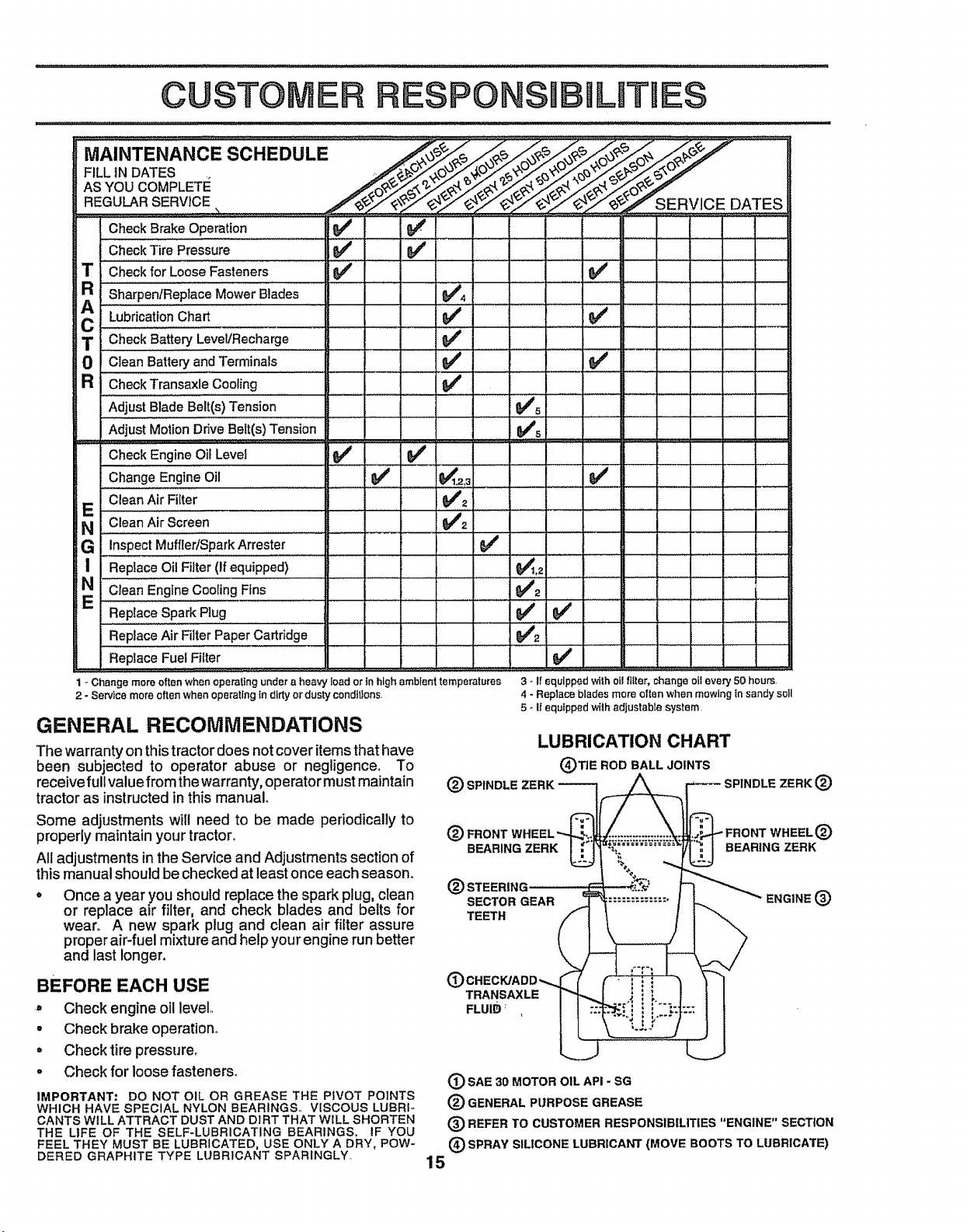
GENERAL RECOMMENDATIONS
The warranty on this tractor does not cover items that have
been subjected to operator abuse or negligence. To
receive full value from the warrant€, operator must maintain
tractor as instructed inthis manual
Some adjustments will need to be made periodically to
properly maintain your tractor.
All adjustments in the Service and Adjustments section of
this manual should be checked at least once each season°
Once a year you should replace the spark plug, clean
or replace air filter, and check blades and belts for
wear. A new spark plug and clean air filter assure
proper air-fuel mixture and help your engine run better
and last longer.
BEFORE EACH USE
° Check engine oil level,,
o Check brake operation_
o Check tire pressure.
° Check for loose fastener&
IMPORTANT: DO NOT OIL OR GREASE THE PIVOT POINTS
WHICH HAVE SPECIAL NYLON BEARINGS° VISCOUS LUBRI-
CANTS WILL ATTRACT DUST AND DIRT THAT WILL SHORTEN
THE LIFE OF THE SELF-LUBRICATING BEARINGS, IF YOU
FEEL THEY MUST BE LUBRICATED, USE ONLY A DRY, POW-
DERED GRAPHITE TYPE LUBRICANT SPARINGLY.
(_) SPINDLE ZERK __
®F.ONT
BEARING ZE RK__ =.........
@
SECTOR GEAR
TEETH
(#
TRANSAXLE
FLUIB _
(D SAE 30 MOTOR OIL API - SG
® GENERAL PURPOSE GREASE
(_) REFER TO CUSTOMER RESPONSIBILITIES "ENGINE" SECTION
(_ SPRAY SILICONE LUBRICANT {MOVE BOOTS TO LUBRICATE)
15
5 - If equtpped wi_hadjustable system.
LUBRICATION CHART
(_)TIE ROD BALL JOINTS
,_SPINDLE ZERK®
FRONT WHEEL®
BEARING ZERK
"ENGINE(_)
TRACTOR
Always observe safety rules whenperforming any mainte-..
nance.
BRAKE OPERATION
If tractor requires more than six (6)feet stopping distance
athigh speed in highest gear, then brake must be adjusted.
(See 'q'O ADJUST BRAKE" in the Service and Adjust-
merits section of this manual).
TIRES
° Maintain proper air pressure in all tires (See "PROD-
UCT SPECIFICATIONS on page 3 of this manual).
* Keep tires free of gasoline, oil, orinsect control chemi-
cals which can harm rubber.
° Avoid stumps, stones, deep ruts, sharp objects and
other hazards that may cause tire damage.
BLADE CARE
For'best results mower blades must be kept sharp° Re_
place bent or'damaged blades.
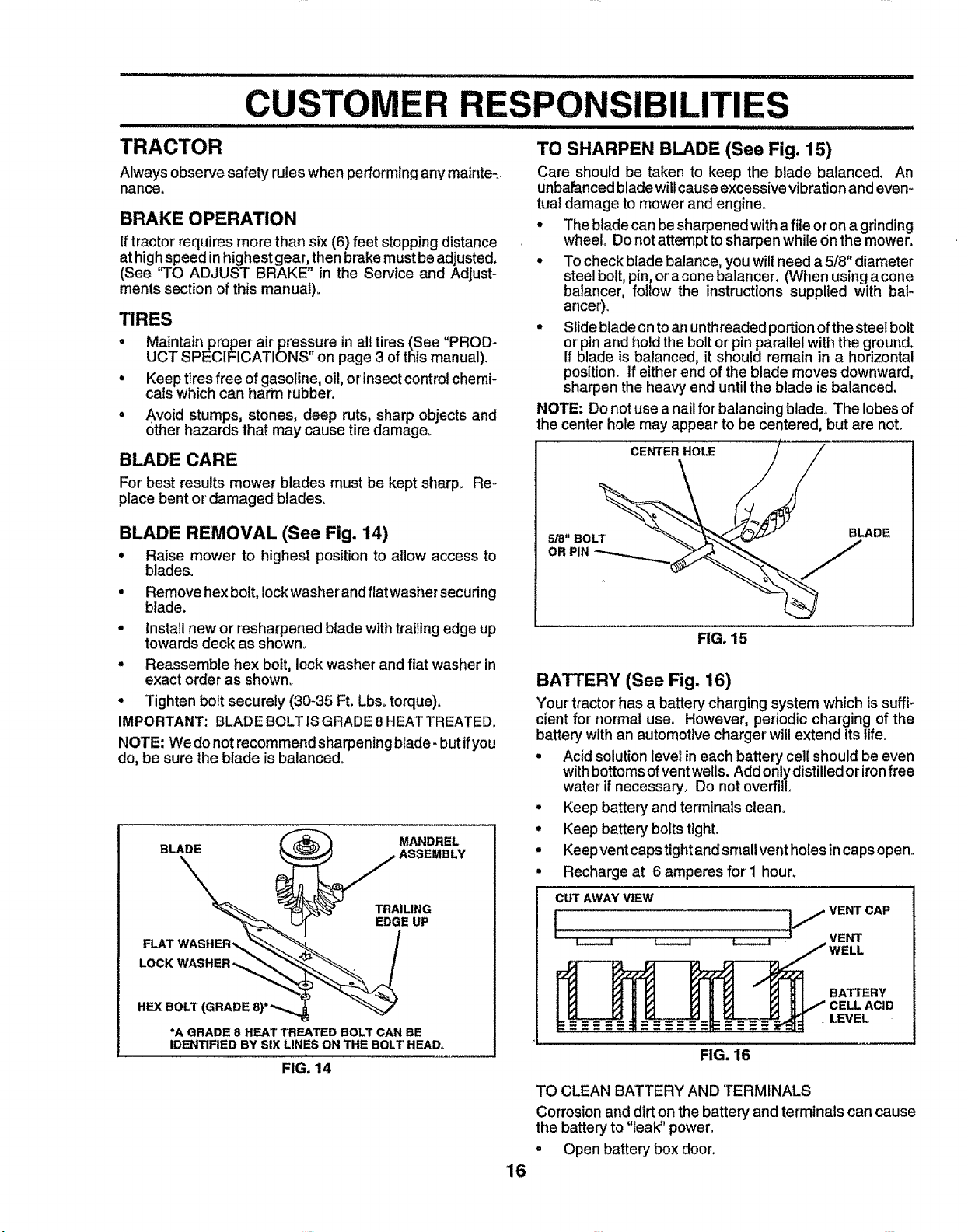
BLADE REMOVAL (See Fig. 14)
° Raise mower to highest position to allow access to
blades.
. Remove hex bolt, lock washer' and flat washer securing
blade.
o Install new or'resharpened blade with trailing edge up
towards deck as shown°
° Reassemble hex bolt, lock washer and flat washer in
exact order as shown°
• Tighten bolt securely (30-35 Ft. Lbs. torque).
IMPORTANT: BLADE BOLT ISGRADE 8 HEATTREATED.,
NOTE: We do not recommend sharpening blade- but ifyou
do, be sure the blade is balanced,,
TO SHARPEN BLADE (See Fig. 15)
Care should be taken to keep the blade balanced, An
unbaPancedbladewillcauseexcessivevibrationand even-
tual damage to mower' and engine_
• The blade can besharpened witha file or on a grinding
wheel., Do not attempt to sharpen while Onthe mower°
• To check blade balance, you will need a 5/8" diameter
steel bolt, pin, or a cone balancer. (When using a cone
batancer, follow the instructions supplied with bal-
ancer).
° Slide blade on to an unthreaded portion ofthe steel bolt
or pin and hold the bolt or'pin parallel with the ground.
If blade is balanced, it should remain in a horizontal
position, tf either' end of the blade moves downward,
sharpen the heavy end until the blade is balanced.
NOTE: Do not use a nail for balancing blade° The lobes of
the center hole may appear to be centered, but are not.
FIG. 15
BATTERY (See Fig. 16)
Your tractor has a battery charging system which is suffi-
cient for normal use, However. periodic charging of the
battery with an automotivecharger'will extend its life_
• Acid solution levelin each battery cellshould be even
withbottoms of ventwells. AddonlydistUledoriron free
water if necessary° Do not overfill,
° Keep battery and terminalsclean,
• Keep battery boltstight,
° Keepvent capstightandsmaUvent holes incaps open,.
° Recharge at 6 amperes for i hour,
CUT AWAY VIEW
*A GRADE 8 HEAT TREATED BOLT CAN BE
IDENTIFIED BY SiX LINES ON THE BOLT HEAD°
FIG. 14
_ _ _ _ VENT
IJ VENT cAP
BATTERY
LEVEL
FIG. 16
TO CLEAN BATTERY AND TERMINALS
Corrosion and dirt on the battery and terminals cart cause
the battery to "Eeak"power.,
- Open battery box door,.
16
CUSTOMER PO BmL E$
o Disconnect BLACK battery cable first then RED bat-
tery cable and remove battery from tractor°
• Wash battery with solution1 of fou_,_tablespoons;,0t_
bakingsodatoonegallon ofwater, Becareful nottoget
the soda solution into the cells.
• Rinse the battery with plain water and dry°
° Clean terminals and battery cable endswith wire brush
until bright.
• Coat terminals with grease or petroleum jelly.
° Reinstall battery (See "INSTALL BATTERY" in the
Assembly section of this manual)°
Check V-belts for deterioration and wear after 100 hours of
operation and replace if necessary° The belts are not
adjustable° Replace belts ifthey begin to slip from wear,
TRANSAXLE COOLING
Keep transaxle free from build-up of dirt and chaffwhich
can restrict cooling.
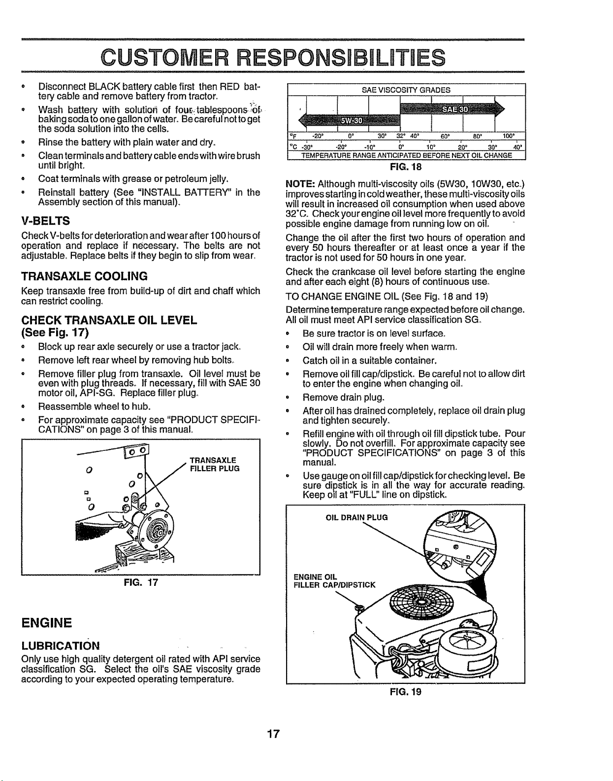
CHECK TRANSAXLE OIL LEVEL
(See Fig. 17)
• Block up rear axle securely or use a tractor jack°
° Remove left rear wheel by removing hub bolts°
o Remove filler plug from transaxle. Oil level must be
even with plug threads. If necessary, fill with SAE 30
motor oil, API-SG. Replace filler plug,
• Reassemble wheel to hub.
o For approximate capacity see "PRODUCT SPECtFlo
CATIONS" on page 3 of this manual.
TRANSAXLE
O
o
O
RLLER PLUG
SAE VISCOSITY GRADES
I =F "20 = 0 ° 30 _ 32" ,10" 60 _' 80" "tO0_
ioc , , ; .....
-30° "20 _' -1 _ 0_ 10" 20 ° 30 ° 40 _
TEMPERATURE RANGE ANTICIPATED BEFORE NEXT OIL CHANGE
FIG, 18
NOTE: Although multi-viscosity oils (5W30, 10W30, etco)
improves starting incold weather, these multi-viscosity oils
will result in increased oil consumption when used above
32"Co Check your engine oil level more frequently to avoid
possible engine damage from running low on oil.
Change the oil after the first two hours of operation and
every 50 hours thereafter or at least once a year if the
tractor is not used for 50 hours in one year,
Check the crankcase oil levet before starting the engine
and after each eight (8) hours of continuous user
TO CHANGE ENGINE OIL (See Fig. 18 and 19)
Determine temperature range expected before oil change,
All oil must meet API service classificationSGo
o Be sure tractor is on level surface°
° Oil will drain more freely when warm.
° Catch oit in a suitable container.
° Remove oil fill cap/dipstick. Be careful not toallow dirt
to enter the engine when changing oil
° Remove drain plug.
° After oil has drained completely, replace oil drainplug
and tighten securely.
• Refiilengine with oilthroughoil fill dipstick tube. Pour
slowly. Do not overfill° For approximate capacity see
"PRODUCT SPECIFICATIONS" on page 3 of this
manual
° Use gauge on oil fill cap!dipstick for checking level. Be
sure dipstick is in all the way for accurate reading.
Keep oil at "FULL" line on dipstick.
FIG, 17
ENGINE
LUBRICATION
Only use high quality detergent oil rated with API service
classification SG. Select the oil's SAE viscosity grade
according to your expected operating temperature,
OIL DRAIN PLUG
ENGINE OIL
FILLER CAP/DIPSTICK
FIG. 19
17
RESPONSIBILITIES
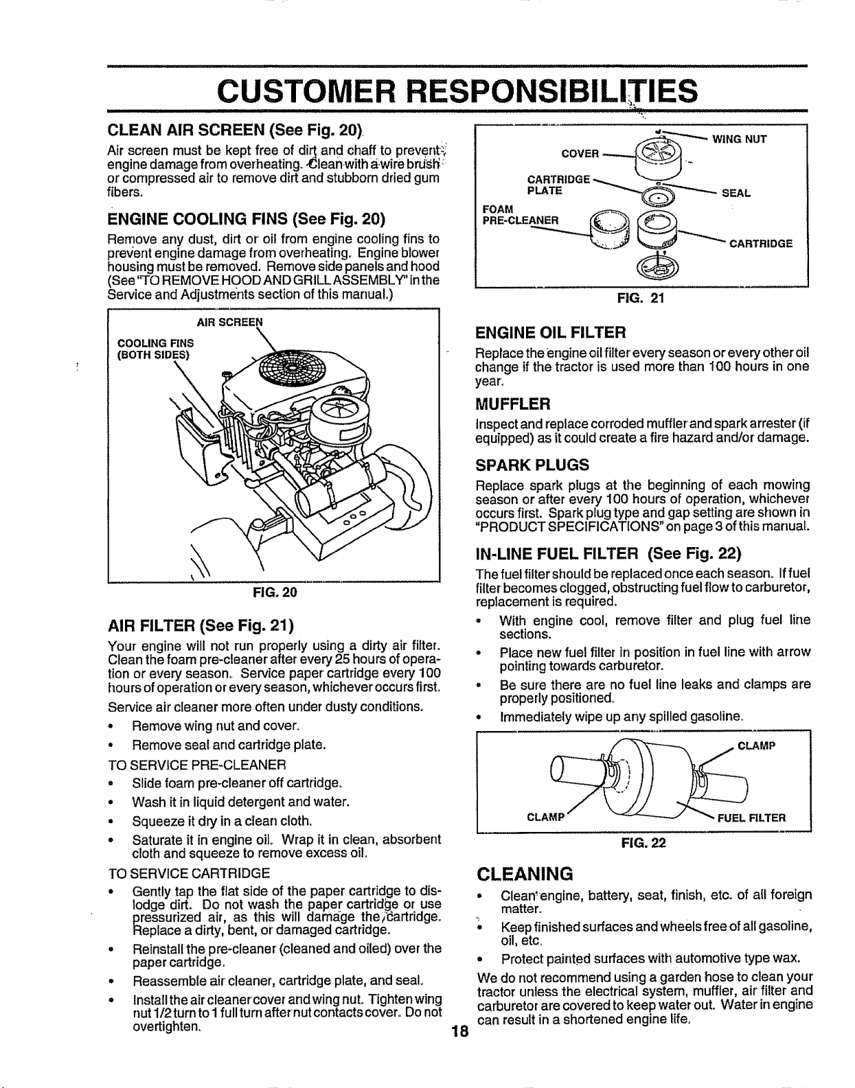
CLEAN AIR SCREEN (See Fig. 20)
Air screen must be kept free of di_ and chaff to prevent:_
engine damage from overheating° ,Cleanwith,_wire brU_h'_
or compressed air to remove dirt and stubborn dried gum
fibers.
ENGINE COOLING FINS (See Fig. 20)
Remove any dust, dirt or oil from engine cooling fins to
prevent engine damage from overheating° Engine blower
housing must be removed. Remove side panels and hood
(See'q'O REMOVE HOOD AND GRILL ASSEMBLY" inthe
Service and Adjustments section of this manuaL)
CARTRIDGE
G
FIG. 21
AIR SCREEN
COOLING RNS
(BOTH SIDES)
\
FIG. 20
AIR FILTER (See Fig. 21)
Your engine will not run properly using a dirty air filter.
Clean the foam pre-cleaner after every25 hoursof opera-
tion or every season,. Service paper cartridge every 100
hours of operationorever':/season,whicheveroccursfirst°
Service air cleaner more often under dusty conditions.
• Remove wing nut and cover.
• Remove seal and cartridgeplate.
TO SERVICE PRE-CLEANER
° Slidefoam pre-cleaner offcartridge°
• Wash it in liquiddetergent and water.
• Squeeze it dry in a clean cloth.
• Saturate it in engine oiL Wrap it in clean, absorbent
clothand squeeze to remove excess oil.
TO SERVICE CARTRIDGE
• Gently tap the fiat side of the paper cartridge to dis-
lodge dirt. Do not wash the paper cartridge or use
pressurizea air, as this will damage the_;_artriageo
Replace a dirty,bent, or damaged cartridge.
. Reinstallthe pre-cleaner (cleaned and oiled) overthe
paper cartridge.
° Reassemble aircleaner, cartridgeplate, and sealo
° Install the air cleaner coverand wing nuL Tighten wing
nut 1/2 turnto 1full turnafternut contactscover° Do not
overtighten.
ENGINE OIL FILTER
Replace the engine oil filter every season or every other oil
change if the tractor is used more than 100 hours in one
year,
MUFFLER
Inspectand replace corroded muffler and spark attester (if
equipped) as it couldcreate a fire hazard and!or damage.
SPARK PLUGS
Replace spark plugs at the beginning of each mowing
season or after every 100 hours of operation, whichever
occursfirst, Spark plugtype and gap setting are shown in
"PRODUCT SPECIFICATIONS" on page 3 of thismanual.
IN-LINE FUEL FILTER (See Fig. 22)
The fuel filter should be replaced once each season. Iffuel
filter' becomes clogged, obstructing fuel flow to carburetor,
replacement is required.
• With engine cool, remove filter and plug fuel line
sections.
° Place new fuel filter in position in fuel line with arrow
pointing towards carburetor.
° Be sure there are no fuel line leaks and clamps are
properlypositioned_
° Immediately wipe up any spilled gasoline.
FIG. 22
CLEANING
= Clean'engine, battery, seat, finish, etc. of all foreign
matter°
Keepfinished surfacesand wheelsfree ofall gasoline,
oil, etc,
° Protectpainted surfaces with automotive type wax.
We do not recommend using a garden hose to clean your
tractor unless the electrical system, muffler, air'filter and
carburetorare coveredto keep waterout. Water inengine
can resultin a shortened engine life.
18
 Loading...