

Craftsman 917255917 Owner’s Manual
SEARS
OWNERS
MANUAL
MODEL NO.
917.255917
Caution:
Read and Follow
All Safety Rules
And Instructions
Before Operating
This Equipment
[RRFTSMRN
GT 18HP TWIN
6 SPEED - 44"" MOWER
GARDEN TRACTOR
Assembly
Operation
Maintenance
Repair and Adjustment
Repair Parts
Sears, Roebuck and Co., Chicago, IL 60684 U.S.A.

SAFETY RULES
1. Know the con_ols, and,J_ow_t_ s_p quickly. READ THIS
OPERA_OB_wS_,_JA&_n_ /pst_ctions furnished with
attachr_nt_
2, Do not allow Children to t_pefate the machine, Do not allow
adults to operate it without proper instruction.
3. Do not carry passengers. Do not mow when children and
others are around.
4, Always wear substantial footwear. Do not wear loose fit-
ting clothing that could get caught in moving parts.
5. Keep your eyes and mind on your tractor, mower and the
area being cut. Do not let other interests distract you.
6. Do not attempt to operate your tractor or mower when
not in the drivers seat.
7. Always get on or off your tractor from the operator's left
hand side.
8. Clear the work area of objects (wire, rocks, etc,) which
might be picked up and thrown.
9. Disengage all attachment clutches before attempting to
start the engine.
10. Disengage power to attachments and stop the engine
before leaving the operator's position•
I 1. Disengage power to mower, stop the engine and discon-
• nect spark plug wire(s) from spark plug(s) before clean-
ing, making an adjustment or repair• Be careful to avoid
touching hot muffler or engine components.
I 2, Disengage power to attachments when transporting or not
in use.
13. Take all possible precautions when leaving the vehicle un-
attended. Disengage the power take off, lower the at-
tachments, shift into neutral, set the parking brake, stop
the engine and remove the key.
! 4. Do not stop or start suddenly when going uphill or
downhill. Mow up and down the face of slopes (not
greater than 15 °); never across the face. Refer to page 51.
1 5. Reduce speed on slopes and make turns gradually to pre-
vent tipping or loss of control. Exercise extreme caution
when changing direction on slopes.
1 6. While going up or down slopes, place Gear Shift Control
Lever in 1st gear position to negotiate the slope without
stopping•
1 7. Never mow in wet or slippery grass, when traction is un-
sure or at a #peed which could cause a skid.
18. Stay alert for holes in the terrain and other hidden hazards:
Keep away from drop-offs.
I 9. Do not drive too close to creeks, ditches and public
high ways.
20. Exercise special care when mowing around fixed objects
in order to prevent the blades from striking them. Never
deliberately run tractor or mower into or over any foreign
objects.
2 1. Never shift gears until tractor comes to a stop.
2 2. Never place hands or feet under the mower, in discharge
chute or near any moving parts while tractor or mower
are running. Always keep clear of discharge chute.
23. Use care when pulling loads or using heavy equipment.
a. Use only approved drawbar hitch points.
b. Limit loads to those you can safely control.
c, Do not turn sharply. Use care when backing.
d, Use counterweight or wheel weights when suggested
in the owner's manual.
24 Watch out for traffic when crossing or near roadways.
2 5 When using any attachments, never direct discharge of
material toward bystanders nor allow anyone near the
vehicle while in operation,
2 6 Handle gasoline with care - it is highly flammable.
a. Use approved gasoline containers .
b. Never remove the fuel cap of the fuel tank or add
gasoline to a running or hot engine or an engine that
has not been allowed to cool for several minutes after
running. Never fill tank indoors, always clean up spill-
ed gasoline.
c, Open doors if the engine is run in the garage exhaust
2 7. Keep the vehicle and attachments in good operating con-
2 8. Keep all nuts, bolts and screws tight to be sure the equip-
2 9. Never store the equipment with gasoline in the tank in-
30. To reduce fire hazard, keep the engine free of grass, leaves
3 1. Except for adjustments; DO NOT operate Engine if air
32. Do not operate without a muffler or tamper with exhaust
33. The vehicle and attachments should be stopped and in-
34. Do not change the engine governor settings or overspeed
35. When using the vehicle with me wet, proceed as follows;
3 6. Do not operate the mower without the deflector shield in
3 7, Disengage power to mower before backing up. Do not
3 B. Under normal usage the grass catcher bag material is sub-
fumes are dangerous. Do not run the engine indoors.
dition, and keep safety devices in place and working,
ment is in safe working condition.
side a building where fumes may reach an open flame or
spark. Allow the engine to cool before storing in any
enclosure.
or excessive grease, Do not clean product while engine
is running•
cleaner or cover directly over carburetor air intake is
removed. Removal of such part could create a fire hazard.
system. Damaged mufflers or spark attesters could create
a fire hazard, Inspect periodicafly and replace if necessary,
spected for damage after striking a foreign object and the
damage should be repaired before restarting and operating
the equipment.
the engine; severe damage or injury may result.
a. Mow only in daylight or in good artificial light.
b. Shut the engine off when unclogging chute.
c. Check the blade mounting bolts for proper tightness
at frequent intervals.
place.
mow in reverse unless absolutely necessary and then on-
ly after careful observation of the entire area behind the
mower,
ject to deterioration and wear. It should be checked fre-
quently for bag replacement. Replacement bags should
be checked to ensure compliance with the original
manufacturer's recommendations or specifications•
LOOK FOR THIS SYMBOL TO POINT OI_T_t4NI_DR_TANT
SAFETY PRECAUTIONS. IT MEANS -- ATTEI_I_N[ BEcoME;
ALERT! YOUR SAFETY IS INVOLVED.
CAUTION: LOOK FOR THIS WORD TO POINT OUT IMPORTANT EQUIP-
MENT PRECAUTIONS.
WARNING: This unit is equipped with an internal combustion engine and should not be used on or near any unimproved forest=covered,
brush-covered or grass covered land unless the engine's exhaust system is equipped with a spark arrester meeting applicable local
or state laws (if any). If a spark arrestor is used, it should be maintained in effective working order by the operator.
In the State of Cahfornia the above is required by law (Section 4442 of the California Public Resources Code). Other states may
have similar laws. Federal laws apply on federal lands• See your Sears Authorized Service Center for spark arrester. See
Repair Parts page 34.
2

CONGRATULATIONS on your purchase of a Sears GT
18HP Garden Tractor. It has been designed, engineered
and manufactured to give you the best possible depen-
dability and performance.
Should you experience any problem you cannot easily
remedy, please contact your nearest Sears Service
Department. They have competent, well-trained techni-
cians and the proper tools to service or repair this unit.
Please read and retain this manual. The instructions will
enable you to assemble and maintain your Tractor pro-
perly. Always observe the "'SAFETY RULES".
MAINTENANCE AGREEMENT
A Sears Maintenance Agreement is available on this
product. Contact your nearest Sears store for details.
YOUR NEW GT 18 HP GARDEN TRAC-
TOR FEATURES...
CRAFTSMAN ! 8 H.P. TWIN- CYLINDER ENGINE--cool-
running performance and long life with plenty of power
to take on a variety of yard, gardening or snow removal
tasks.
MODEL
NUMBER
SERIAL
NUMBER
DATE OF
PURCHASE
THE MODEL AND SERIAL NUMBERS WILL BE
FOUND ON THE MODEL PLATE ATTACHED TO
THE FENDER.
YOU SHOULD RECORD BOTH SERIAL NUMBER
AND DATE OF PURCHASE AND KEEP iN A
SAFE PLACE FOR FUTURE REFERENCE.
ALL GEAR TRANSAXLE--six speeds forward, two
reverse speeds--to let you select the proper speed for
the terrain and the job. Automotive--type differential
helps guard against turf scuffing.
CONTROL PANEL--with Throttle, Choke, Light Switch,
Ignition Switch, Parking Brake Lever and Clutch Switch--
conveniently grouped for ease of use.
ATIACHMENT VERSATfLITY--handles a large variety of
Sears Yard and Garden Tractor Attachments. See
pages 49-50.
CUSTOMER RESPONSIBILITIES
Read and observe the safety rules. Always use care when using your tractor. Keep away from moving parts.
DO NOT work on your tractor with engine running. Always keep your tractor and mower clean.
Follow a regular schedule in maintaining, caring for and using your tractor. A well cared for tractor will run and last longer.
Follow the instructions under "Maintenance" and "Storage" sections of this Owner's Manual.
LIMITED TWO YEAR WARRANTY
ON ELECTRIC START RIDING EQUIPMENT
For two years from date of purchase, when this riding equipment is maintained, lubricated, and tuned up
according t° the operating and maintenance instruction in the owner's manual, Sears will repair free of charge
any defect in material or workmanship in this electric start riding equipment.
This warra.nty excludes blade(s), blade adapter(s), spark plug(s), air cleaner and belt(s), which are expen-
dable and become worn during normal use.
This warranty does not cover:
Tire replacement or repair caused by punctures from outside objects (such as nails, thorns, stumps,
or glass); and
repairs necessary because of operator abuse or negfigence, including the failure to maintain the
equipment according to instructions contained in the owner's manual; and
riding equipment used for commercial or rental purposes.
FULL 90-DAY WARRANTY ON BATTERY
For 90 days from the date of purchase, if any battery included with this riding equipment proves defective
in material or workmanship and our testing determines the battery will not hold a charge, Sears will replace
the battery at no charge.
WARRANTY SERVICE tS AVAILABLE BY CONTACTING THE NEAREST SEARS SERVICE CENTER/DEPART-
MENT IN THE UNITED STATES. This warranty applies only while this product is in use in the United States.
This warranty gives you specific legal rights, and you may also have other rights which may vary from state
to state.
SEARS, ROEBUCK and CO., D/698-731A, Sears Tower, Chicago, II 60684
34
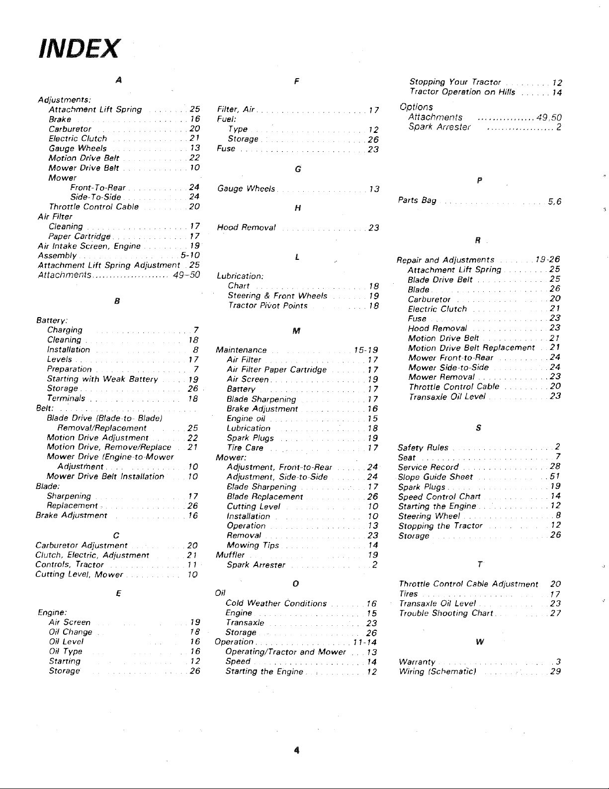
INDEX
Adjustments:
Attachment Lift Spring ........ 25
Brake ...................... 16
Carburetor .................. 20
Electric Clutch ............... 21
Gauge Wheels ............... 13
Motion Drive Belt ............. 22
Mower Drive Belt ............. 10
Mower
Front-To-Rear ........... 24
Side-To-Side ............ 24
Throttle Control Cable ......... 20
Air Filter
Cleaning .................... 17
Paper Cartridge ............... 17
Air Intake Screen, Engine ......... 19
Assembly ................... 5-10
Attachment Lift Spring Adjustment 25
Attachments ...................... 49-50
Battery:
Charging ................... 7
Cleaning ................ 18
Installation 8
Levels ...................... 17
Preparation ................... 7
Starting with Weak Battery ..... 19
Storage .................... 26
Terminals .................. t 8
Belt: ...........................
Blade Drive (Blade to Blade)
Removal/Replacement .... 25
Motion Drive Adjustment ...... 22
Motion Drive, Remove/Replace 21
Mower Drive (Engine-to Mower
Adjustment ............... 10
Mower Drive Belt Installation 10
Blade:
Sharpening ............... 17
Replacement .......... 26
Brake Adjustment ............. 16
C
Carburetor Adjustment ........... 20
Clutch, Electric, Adjustment 21
Controls, Tractor ............... 11
Cutting Level, Mower ........... 10
Engine:
Air Screen ...... 19
Oil Change 18
Oil Level 16
Oil Type 16
Starting .......... 12
Storage ................ 26
Filter, Air ...................... 17
Fuel:
Type ....................... 12
Storage .................... 26
Fuse .............. 23
G
Gauge Wheels .................. 73
H
Hood Removal ................. 23
Lubrication:
Chart ...................... 18
Steering & Front Wheels ....... 19
Tractor Pifzot Points ........ 18
M
Maintenance .............. 15-19
Air Filter ................... 17
Air Filter Paper Cartridge ....... 17
Air Screen ................... 19
Battery ..................... 17
Blade Sharpening ............ 17
Brake Adjustment ............. 16
Engine oil ................... 15
Lubrication ................... 18
Spark Plugs ................. 19
Tire Care .... 17
Mower:
Adjustment, Front-to-Rear ...... 24
Adjustment, Side to Side ....... 24
Blade Sharpening ............. 17
Blade Replacement ............ 26
Cutting Level ........... 10
Installation ............... 10
Operation ................... 13
Removal ................... 23
Mowing Tips ............... 14
Muffler ................... 19
Spark Arrester .............. 2
0
Oil
Cold Weather Conditions ....... 16
Engine ............ 15
Transaxle ................... 23
Storage ...................... 26
Operation ................... 11-14
Operating/Tractor and Mower t3
Speed ...................... 14
Starting the Engine ............ 12
Stopping Your Tractor ......... 12
Tractor Operation on Hills ..... 14
Options
Attachments
Spark Attester
Parts Bag ................... 5, 6
Repair and Adjustments ....... 1,9-26
Attachment Lift Spring ......... 25
Blade Drive Belt ............. 25
Blade ..................... 26
Carburetor ................. 20
Electric Clutch .............. 21
Fuse ...................... 23
Hood Removal .............. 23
Motion Drive Belt ............ 21
Motion Drive Belt Replacement 21
Mower Front-to-Rear .......... 24
Mower Side-to-Side ........... 24
Mower Removal ............. 23
Throttle Control Cable ........ 20
Transaxle Oil Level ............ 23
Safety Rules .................... 2
Seat ......................... 7
Service Record ................. 28
Slope Guide Sheet ............. 51
Spark Plugs ................... 19
Speed Control Chart ............ 14
Starting the Engine .............. 12
Steering Wheel .................. 8
Stopping the Tractor ......... 12
Storage ..................... 26
Throttle Control Cable Adjustment 20
Tires ....................... 17
Transaxle Oil Level ............ 23
Trouble Shooting Chart ......... 27
Warranty ..................... 3
Wiling (Schematic) .............. 29
................ 49,50
................... 2
P
R •
T ¸
W

A SSEMBL Y
Know Your Tractor
READ THIS OWNER'S MANUAL BEFORE OPERATING YOUR GARDEN TRACTOR. If you unders-
tand the machine and its operation, you will achieve efficient and peak performance. While reading
the manual, compare the illustrations with your Garden Tractor to familiarize yourself with the loca-
tion of various controls and adjustments. Study the operating instructions and safety precautions
thoroughly to insure proper functioning of your Garden Tractor and to prevent injury to yourself
and others. Be sure to pay strict attention to all notes and cautions; they are included for your safe-
ty. Save this manual for future reference.
Unpacking Instructions
1, Remove. box from carton. The box contains the/terns
shown below.
2. Cut down four corners of the carton with a utility
knife and fold down sides.
3. Remove mower deck from skid.
4. Oisengage Parking Brake.
5. Carefully guide the tractor backwards off the skid.
C.
The operation of any tractor can result in
foreign objects thrown i#to the eyes, which
can result in severe eye damage. Always
wear safety glasses or eye shields before
starting your tractor and while mowing. We
recommend Wide Vision Safety Mask for
over the spectacles or standard safety
glasses, available at Sears Retail or Catalog
Stores.
Parts Bag Contents Not Shown Full Size:
"¢_l_llwJlll K ' '
(2) Battery Carriage Bolts - 1/4 - 20 x 7 - 1/2
Terminal Guard
e.
a, seat
b. steering wheel
c. battery
d. battery acid
e. owner's manual
f. parts ba9
15 0 Slope Instruction Sheet
V-Belt
(2) Keys
BA T FERY
CAPS &
iNSTRUCTIONS
Steering Wheel Cap

ASSEMBL Y
A SSEMBL Y
LOCA "lION
BA TTERY
BATTERY
TERMINALS
PARTS BAG CONTENTS SHOWN FULL SIZE
(2) Lockwasher, 1/4 Int/Ext Tooth
(2) Hex Bolt, I/4-20x 3/4
©
(2) Lockwasher 1/4
(2) Wing Nut - 1/4 - 20
(2) Washer 9/32 x 5/8 x 16 Ga. Q
(2) Hex Nut, 1/4 - 20
SUSPENSION
ARMS
SEA T
(4) Spring Retainer (4) Washer 17/32x 1 - !/16x 13 Ga.
(I) Hex Bolt, 1/2 - 13 x I
Grade 5
(1) Shoulder Bolt 5/16 - 18
(J) Lockwasher 1/2
(1) Washer 17/32 x I-3/16
x 12 Ga.
(1) Washer 15/32x i x 16 Ga.
To assemble and adjust your tractor you wil! need:
ASSEIVIBL Y
(2) 7/!6- wrenches (2) 1/2" wrenches
(1) 3/4"" wrench Tire Pressure Gauge
II
NOTE: RIGHT HAND IR.H.)AND LEFT HAND (L.H.)ARE
DETERMINED FROM OPERATOR'S POSITION WHILE
SEATED ON THE TRACTOR.
NOTE: THIS TRACTOR IS EQUIPPED WITH AN
OPERATOR PRESENCE SENSING SWITCH, ANY AT-
TEMPT BY THE OPERATOR TO LEAVE THE SEAT WITH
THE ENGINE RUNNING AND ATTACHMENT CLUTCH
ENGAGED WILL SHUT OFF THE ENGINE.
(!) 9/16"" wrenches Screwdriver
Utility Knife
WEAR EYE AND FACE SHIELD.
MEDIATELY IF ACCIDENTALLY IN CON-
WASH HANDS OR CLOTHING IM-
TACT WITH ELECTROLYTE.
DO NOT SMOKE, FUMES FROM CHARG-
ED ELECTROLYTE ARE EXPLOSIVE.
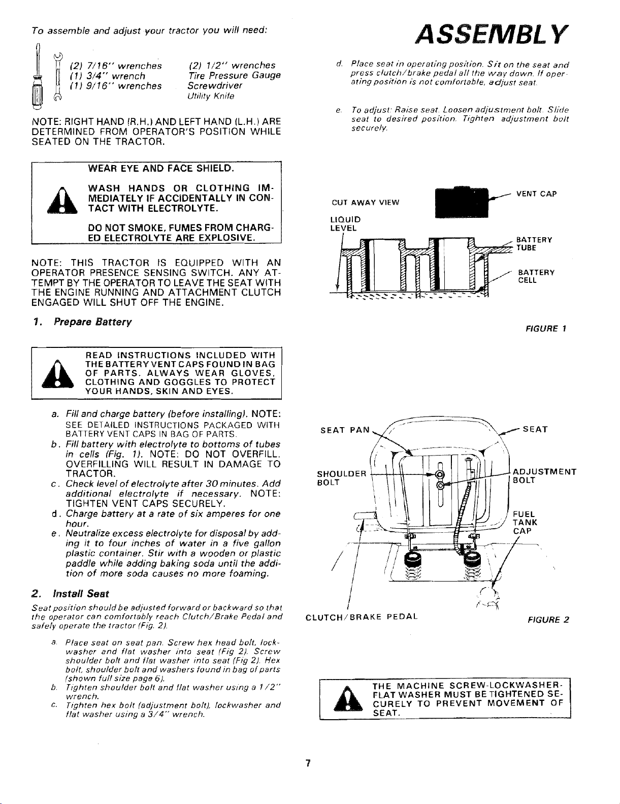
1. Prepare Battery
READ INSTRUCTIONS INCLUDED WITH
THE BATTERYVENT CAPS FOUND IN BAG
OF PARTS. ALWAYS WEAR GLOVES.
CLOTHING AND GOGGLES TO PROTECT
YOUR HANDS, SKIN AND EYES.
d,
Place seat in operating position. Sit on the seat and
press clutch/brake pedal all the way down. if oper
atlng position is not comfortable, adjust seat
To adjust" Raise seat. Loosen adjustment bolt Slide
seat to desired position, Tl_qhten adjustment belt
securely.
CUT AWAY VIEW
LIQUID
LEVEL
VENT CAP
BATTERY
TUBE
BATTERY
CELL
FIGURE 1
a. Fill and charge battery (before installing). NOTE:
SEE DETAILED INSTRUCTIONS PACKAGED WITH
BATTERY VENT CAPS IN BAG OF PARTS.
b. Fill battery with electrolyte to bottoms of tubes
in cells (Fig. 1). NOTE: DO NOT OVERFILL.
OVERFILLING WILL RESULT IN DAMAGE TO
TRACTOR.
c. Check level of electrolyte after 30 minutes. Add
additional electrolyte if necessary. NOTE:
TIGHTEN VENT CAPS SECURELY.
d. Charge battery at a rate of six amperes for one
hour.
e, Neutralize excess electrolyte for disposal by add-
ing it to four inches of water in a five gallon
plastic container. Stir with a wooden or plastic
paddle while adding baking soda until the addi-
tion of more soda causes no more foaming.
2. Install Seat
Seat position should be adjusted forward or backward so that
the operator can comfortably reach Clutch/Brake Pedal and
safely operate the tractor (Fig 2).
a. Place seat on seat pan. Screw hex head bolt, lock-
washer and flat washer into seat (Fig 2). Screw
shoulder bolt and flat washer into seat (Fig 2), Hex
bolt, shoulder bolt and washers found in bag of parts
(shown full size page 5),
b. Tighten shoulder bolt and flat washer usmg a 1/2""
wrench.
c. Tighten hex bolt (adjustment bolt), /ockwasher and
flat washer using a 3/4"" wrench.
SEAT PAN
SHOULDER
BOLT i
!
/
/
CLUTCH/BRAKE PEDAL
THE MACHINE SCREW-LOCKWASHER-
FLAT WASHER MUST BE TIGHTENED SE-
CURELY TO PREVENT MOVEMENT OF
SEAT.
ADJUSTMENT
BOLT
FUEL
TANK
CAP
(
FIGURE 2

ASSEMBL Y
3. Install Steering Wheel
NOTE: POSITION FRONT WHEELS FORWARD,
FIGURE 3
BATTERY
COMPARTMENT
STEERING WHEEL CAP
HEX BOLT
LOCKWASHER
2 - 318" DIA. WASHER
STEERING WHEEL
--- STEERING WHEEL ADAPTER
STEERING SHAFT
a. Use a 9/16" wrench to remove hex bolt,
Iockwasher and 2-3/8" diameter washer (shown
full size below) from steering shaft (Fig, 3)
HOOD
b. Position steering wheel over steering adaptor.
c. Secure steering wheel to steering shaft using
hex bolt, Iockwasher and 2=3/8"" diameter
washer (Fig. 3).
FIGURE 4
LOCKWASHER
GRILL
WASHER
HEX
BOLTS
BLACK
(NEGATIVE)
CABLE
NUT
d. Snap steering wheel cap in place on steering
wheel. Steering wheel cap found in bag of parts.
4. Check Tires
Reduce tire.pressure to 14 PSI in front and 10 PSI in rear
tires, (Tires were overinflated for shipping purposes).
DO NOT SHORT BATTERY TERMINALS.
BEFORE INSTALLING BATTERY, REMOVE
METAL BRACELETS, WRISTWATCH
BANDS, RINGS, ETC.
ER
5. Install Battery
a. Remove hood - See page 23.
b. Remove tape from plastic tray. Make sure drain
tube (Fig. 5) is fastened to drain hole in battery
tray and battery tray is positioned in hole of bat-
tery support.
c . Place battery in plastic tray (Battery terminals to
front of tractor)(Fig. 5).
FIGURE 5
DRAIN TUBE
NECTED FIRST TO PREVENT SPARKS
POSITIVE TERMINAL MUST BE CON- 1
FROM ACCIDENTAL GROUNDING.
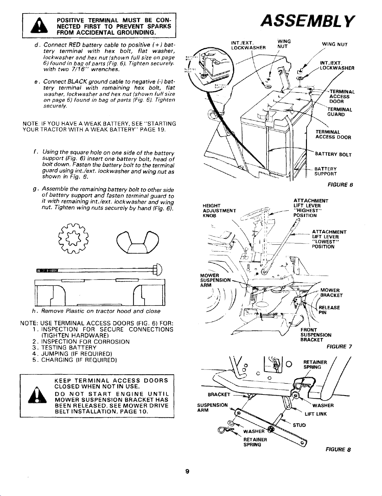
d,
Connect RED battery cable to positive (+) bat-
tery terminal with hex bolt, flat washer,
Iockwasher and hex nut (shown full size on page
6) found in bag of parts (Fig. 6). Tighten securely,
with two 7/16" wrenches.
e,
Connect BLACK ground cable to negative (-) bat-
tery terminal with remaining hex bolt, flat
washer, Iockwasher and hex nut (shown full size
on page 5) found in bag of parts (Fig. 6). Tighten
securely.
NOTE: IF YOU HAVE A WEAK BATTERY, SEE "STARTING
YOUR TRACTOR WITH AWEAK BATTERY" PAGE 19.
f.
Using the square hole on one side of the battery
support (Fig. 6) insert one battery bolt, head of
bolt down. Fasten the battery bolt to the terminal
guard using int./ext. Iockwasher and wing nut as
shown in Fig. 6.
g°
Assemble the remaining battery bolt to other side
of battery support and fasten terminal guard to
it with remaining int./ext. Iockwasher and wing
nut. Tighten wing nuts securely by hand (Fig. 6).
/
\
HEIGHT
ADJUSTMENT
KNOB
INT./EXT.
LOCKWASHER
ASSEMBL Y
WING
NUT WING NUT
,,_ INT./EXT.
LOCKWASHER
ACCESS
DOOR
,L
BOLT
TERMINAL
ACCESS DOOR
BATTERY
SUPPORT
ATTACHMENT
LIFT LEVER
"HIGHEST'"
POSITION
GUARD
FIGURE 6
),L
0
h. Remove Plastic on tractor hood and close
NOTE: USE TERMINAL ACCESS DOORS (FIG. 6) FOR:
1 INSPECTION FOR SECURE CONNECTIONS
(TIGHTEN HARDWARE)
2 INSPECTION FOR CORROSION
3 TESTING BATTERY
4 JUMPING (IF REQUIRED)
5 CHARGING (IF REQUIRED)
KEEP TERMINAL ACCESS DOORS
CLOSED WHEN NOT IN USE.
DO NOT START ENGINE UNTIL
MOWER SUSPENSION BRACKET HAS
BEEN RELEASED. SEE MOWER DRIVE
BELT INSTALLATION, PAGE 10.
ARM
y
BRACKET
SUSPENSION
ARM
r i_
ATTACHMENT
.... "'LOWEST'"
LIFT LEVER
POSITION
RELEASE
FRONT
SUSPENSION
BRACKET
FIGURE 7
RETAINER
SPRING
LIFT LINK
STUD
RETAINER
SPRING
FIGURE 8
9
A
PRIMARY
MANDREL
FIGURE 9
WHEEL
GAUGE/
BAR
GAUGE
WHEEL
\
_CLEVIS
FIGURE 10/I PIN
CLUTCH
PULLEY
LEVER
TENSION
PULLEY
_GURE 11
Y
MOWER DRIVE
BELT
FRONT
SUSPENSION
BRACKET
BRACKET
MOWER
DRIVE
BELT
IDLER
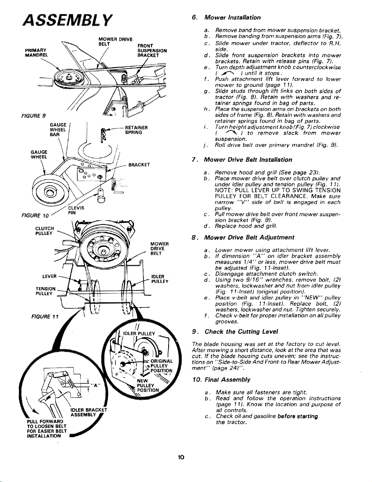
6. Mower Installation
a. Remove band from mower suspension bracket.
b . Remove banding from suspension arms (Fig. 7),
c. Slide mower under tractor, deflector to R.H.
side.
d. Slide front suspension brackets into mower
brackets. Retain with release pins (Fig. 7).
e. Turn depth adjustment knob counterclockwise
( _ ) until it stops.
f. Push attachment lift lever forward to lower
mower to ground (page 11),
g. Slide studs through lift links on both sides of
tractor (Fig. 8). Retain with washers and re-
tainer springs found in bag of parts.
h. Place the suspension arms on brackets on both
sides of frame (Fig. 8). Retain with washers and
retainer springs found in bag of parts,
Turn height adjustment knob (Fig. 7) clockwise
( _ ) to remove slack from mower
suspension.
I. Roll drive belt over primary mandrel (Fig. 9).
7. Mower Drive Belt Installation
a. Remove hood and grill (See page 23).
b. Place mower drive belt over clutch pulley, and
under idler pulley and tension pulley (Fig, 11).
NOTE: PULL LEVER UP TO SWING TENSION
PULLEY FOR BELT CLEARANCE. Make sure
narrow "'V'" side of belt is engaged in each
pulley.
c . Putl mower drive belt over front mower suspen-
sion bracket (Fig. 9).
d. Replace hood and grill.
8. Mower Drive Belt Adjustment
a. Lower mower using attachment lift lever.
b. If dimension "A'" on idler bracket assembly
measures !/4"" or less, mower drive belt must
be adjusted (Fig. 1 I-Inset).
c. Disengage attachment clutch switch.
d. Using two 9/16" wrenches, remove bolt, (2)
washers, Iockwasher and nut from idler pulley
(Fig. 1 l-Inset) (original position).
e. Place v-belt and idler pulley in "'NEW" pulley
position (Fig. 1I-Inset). Replace bolt, (2)
washers, Iockwasher and nut, Tighten securely.
f . Check v-belt for proper installation on all pulley
grooves.
9. Check the Cutting Level
PULL FORWARD
TO LOOSEN BELT
FOR EASIER BELT
INSTALLATION
IDLER BRACKET
The blade housing was set at the factory to cut level.
After mowing a short distance, look at the area that was
cut. If the blade housing cuts uneven; see the instruc-
tions on "'Side-to-Side And Front-to Rear Mower Adjust-
ment" (page 24)".
10. Final Assembly
a. Make sure all fasteners are tight.
b. Read and follow the operation instructions
(page 1!). Know the location and purpose of
all controls.
c. Check oil and gasoline before starting
the tractor.
!O
OPERA TION
KNOW YOUR TRACTOR
READ THIS OWNER'S MANUAL BEFORE OPERATING YOUR GARDEN TRACTOR. If you understand the machine and
its operation, you will achieve efficient and peak performance. While reading the manual, compare the illustrations with
you Garden Tractor to familiarize yourself with the location of various controls and adjustments. Study the operating
instructions and safety precautions thoroughly to insure proper functioning of your Garden Tractor and to prevent in-
jury to yourself and others. Be sure to pay strict attention to all notes and cautions; they are included for your safety.
Save this manual for future reference.
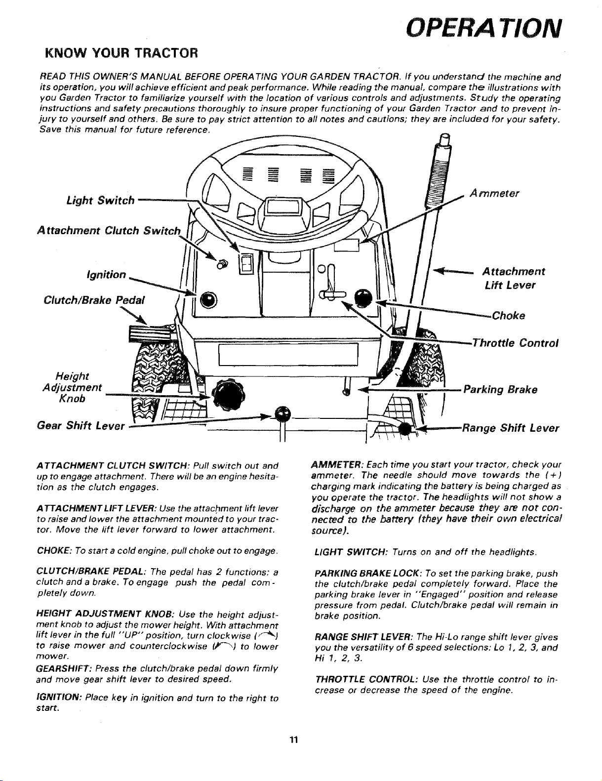
Light Switch
A ttachment Clutch Switch
Clutch/Brake Pedal
Height
Adjustment
Knob
Gear Shift Lever
ATTACHMENT CLUTCH SWITCH: Pull switch out and
up to engage attachment. There will be an engine hesita-
tion as the clutch engages.
A TTACHMENT LIFT LEVER: Use the attachment lift lever
to raise and lower the attachment mounted to your trac-
tor. Move the lift lever forward to lower attachment.
Arnmeter
Attachment
Lift Lever
.Choke
,ttle Control
Parking Brake
,ge Shift Lever
AMMETER: Each time you start your tractor, check your
ammeter. The needle should move towards the (+)
charging mark indicating the battery is being charged as
you operate the tractor. The headlights will not show a
discharge on the ammeter because they are not con-
nected to the battery (they have their own electrical
source).
CHOKE: To start a cold engine, pull choke out to engage.
CLUTCH/BRAKE PEDAL: The pedal has 2 functions: a
clutch and a brake. To engage push the pedal com-
pletely down.
HEIGHT ADJUSTMENT KNOB: Use the height adjust-
ment knob to adjust the mower height. With attachment
lift lever in the full "'UP" position, turn clockwise (F_.)
to raise mower and counterclockwise (/f_) to lower
mower.
GEARSHIFT: Press the clutch/brake pedal down firmly
and move gear shift lever to desired speed.
IGNITION: Place key in ignition and turn to the right to
start.
LIGHT SWITCH: Turns on and off the headlights.
PARKING BRAKE LOCK: To set the parking brake, push
the clutch/brake pedal completely forward. Place the
parking brake lever in "Engaged" position and release
pressure from pedal. Clutch/brake pedal will remain in
brake position.
RANGE SHIFT LEVER: The Hi-Lo range shift lever gives
you the versatility of 6 speed selections: Lo 1, 2, 3, and
Hil, 2,3.
THROTTLE CONTROL: Use the throttle control to in-
crease or decrease the speed of the engine.
11
OPERA TION
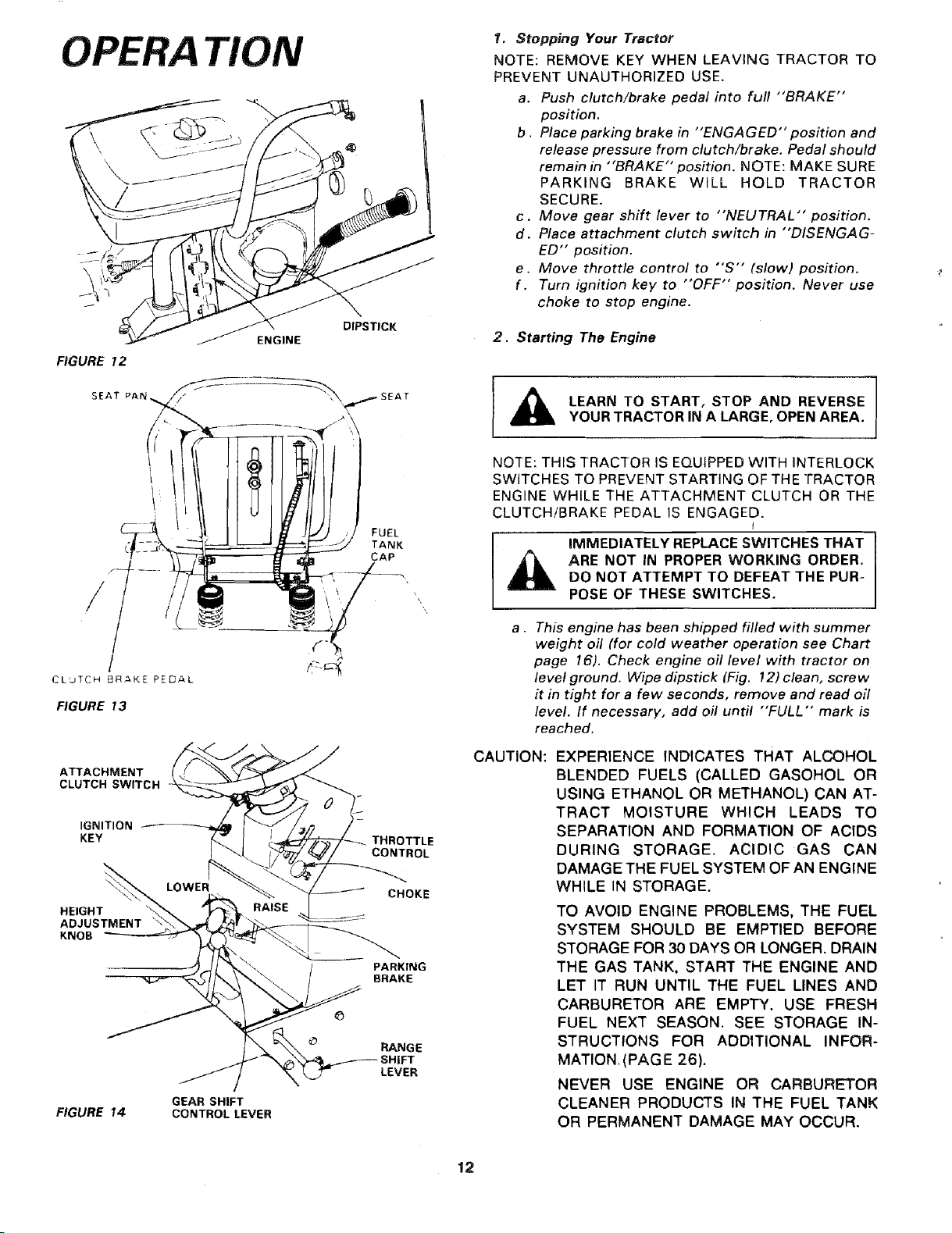
ENGINE
FIGURE 12
SEAT PAP,
DIPSTICK
1. Stopping Your Tractor
NOTE: REMOVE KEY WHEN LEAVING TRACTOR TO
PREVENT UNAUTHORIZED USE.
a. Push clutch/brake pedal into full "'BRAKE'"
position.
b. Place parking brake in "ENGAGED" position and
release pressure from clutch/brake. Pedal should
remain in "BRAKE" position. NOTE: MAKE SURE
PARKING BRAKE WILL HOLD TRACTOR
SECURE.
c . Move gear shift lever to "NEUTRAL" position.
d. Place attachment clutch switch in "DISENGAG-
ED" position.
e. Move throttle control to "'S'" (slow) position.
f . Turn ignition key to "OFF" position. Never use
choke to stop engine.
2. Starting The Engine
_ LEARN TO START, STOP AND REVERSE
NOTE: THIS TRACTOR IS EQUIPPEDWITH INTERLOCK
SWITCHES TO PREVENT STARTING OF THE TRACTOR
ENGINE WHILE THE ATTACHMENT CLUTCH OR THE
CLUTCH/BRAKE PEDAL IS ENGAGED.
YOURTRACTORIN A LARGE, OPEN AREA.
\
a. This engine has been shipped filled with summer
weight oil (for cold weather operation see Chart
CLUTCH BRAKE PEDAL
/
FIGURE 13
CAUTION: EXPERIENCE INDICATES THAT ALCOHOL
CLUTCH SWI;CH
A AO.M.NT
page 16). Check engine oil level with tractor on
level ground. Wipe dipstick (Fig. !2) clean, screw
it in tight for a few seconds, remove and read oil
level. If necessary, add oil until "FULL'" mark is
reached.
,O.,T.O. ,-
T.ROTTLE
"-L.!/"°_d_V/ CONTROL
LOWE%. Z_--J c.oK.
ADJUSTMENT \"S_,,_r_r ",_,_;._ .....
.....-_------_)..Jl ,'_ "\, / PARKING
N.F ,_//X_ \_ _ _' BRAKE
___ sHIFT
/ \ LEVER
FIGURE 14 CONTROLLEVER
GEAR SHIFT
IMMEDIATELY REPLACE SWITCHES THAT
ARE NOT IN PROPER WORKING ORDER.
DO NOT ATTEMPT TO DEFEAT THE PUR-
POSE OF THESE SWITCHES.
BLENDED FUELS (CALLED GASOHOL OR
USING ETHANOL OR METHANOL) CAN AT-
TRACT MOISTURE WHICH LEADS TO
SEPARATION AND FORMATION OF ACIDS
DURING STORAGE. ACIDIC GAS CAN
DAMAGE THE FUEL SYSTEM OF AN ENGINE
WHILE IN STORAGE.
TO AVOID ENGINE PROBLEMS, THE FUEL
SYSTEM SHOULD BE EMPTIED BEFORE
STORAGE FOR 30 DAYS OR LONGER. DRAIN
THE GAS TANK, START THE ENGINE AND
LET IT RUN UNTIL THE FUEL LINES AND
CARBURETOR ARE EMPTY. USE FRESH
FUEL NEXT SEASON. SEE STORAGE IN-
STRUCTIONS FOR ADDITIONAL INFOR-
MATION. (PAG E 26).
NEVER USE ENGINE OR CARBURETOR
CLEANER PRODUCTS IN THE FUEL TANK
OR PERMANENT DAMAGE MAY OCCUR.
12
b. Fill fuel tank (Fig. 13). Use fresh, clean, regular
unleaded automotive gasoline. (Use of leaded
gasoline will increase carbon and lead oxide
deposits and reduce valve life). Capacity is 3- 1/2
gallons,
c. Place attachment clutch switch in "'DISENGAG-
ED" position,
d. Push clutch/brake pedal fully into brake position,
e. Place gear shift lever in "'N'" neutral, start posi-
tion (Fig. 14).
f . Place range shift lever in "N'" neutral position (Fig.
14).
g. Pull choke out (Fig. 14),
h . Move throttle control to middle position (Fig, 14).
i. Turn ignition to "START" position until engine
starts (Fig. 14). NOTE: DO NOT RUN STARTER
CONTINUOUSLY FOR MORE THAN FIFTEEN
SECONDS PER MINUTE. If engine does not start
after several attempts, move throttle control to
"'F'" (fast) position, wait a few minutes and try
again.
j. After engine is warm, push choke in.
The first time you start the engine, it will take extra
cranking time to move fuel from tank to engine. NOTE:
ALLOW ENGINE TO WARM UP FOR A FEW MINUTES
BEFORE ENGAGING CLUTCH/BRAKE PEDAL OR AT-
TACHMENT CLUTCH SWITCH.
k. When restarting a warm engine, move throttle
control midway between "'S'" (slow) and "'F'"
(fast) position. Choke may not have to be used.
TION
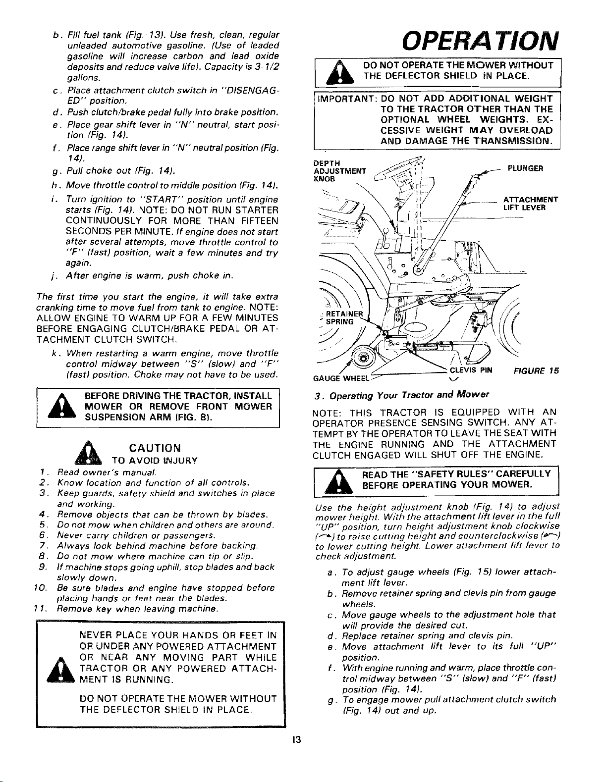
THE DEFLECTOR SHIELD IN PLACE.
DO NOT OPERATE THE MOWER WITHOUT
IMPORTANT: DO NOT ADD ADDITIONAL WEIGHT
TO THE TRACTOR OTHER THAN THE
OPTIONAL WHEEL WEIGHTS. EX-
CESSIVE WEIGHT MAY OVERLOAD
AND DAMAGE THE TRANSMISSION.
DEPTH
ADJUSTMENT
KNOB
_:RETAINER
SPRING
GAUGE WHEEL _--
CLEVIS PIN FIGURE 15
PLUNGER
ATTACHMENT
LIFT LEVER
I ,_ BEFORE DRIVING THE TRACTOR, INSTALL
7 .
2.
3.
SUSPENSION ARM (FIG. 8,.
CAUTION
TO AVOID INJURY
Read owner's manual.
Know location and function of all controls.
Keep guards, safety shield and switches in place
and working.
MOWER OR REMOVE FRONT MOWER
4.
Remove objects that can be thrown by blades.
5.
Do not mow when children and others are around.
6.
Never carry children or passengers.
7.
Always look behind machine before backing.
8.
Do not mow where machine can tip or slip.
9.
If machine stops going uphill, stop blades and back
slowly down.
10.
Be sure blades end engine have stopped before
placing hands or feet near the blades.
lf.
Remove key when leaving machine.
ii-,llli.i
NEVER PLACE YOUR HANDS OR FEET IN
OR UNDER ANY POWERED ATTACHMENT
OR NEAR ANY MOVING PART WHILE
TRACTOR OR ANY POWERED ATTACH-
MENT IS RUNNING.
DO NOT OPERATE THE MOWER WITHOUT
THE DEFLECTOR SHIELD IN PLACE,
3. Operating Your Tractor and Mower
NOTE: THIS TRACTOR IS EQUIPPED WITH AN
OPERATOR PRESENCE SENSING SWITCH. ANY AT-
TEMPT BY THE OPERATOR TO LEAVE THE SEAT WITH
THE ENGINE RUNNING AND THE ATTACHMENT
CLUTCH ENGAGED WILL SHUT OFF THE ENGINE.
BEFORE OPERATING YOUR MOWER.
READ THE "SAFETY RULES" CAREFULLY
Use the height adjustment knob (Fig. 14) to adjust
mower height. With the attachment lift lever in the full
"'UP" position, turn height adjustment knob clockwise
("-_) to raise cutting height and counterclockwise (_-_)
to lower cutting height. Lower attachment lift lever to
check adjustment.
a. To adjust gauge wheels (Fig. 15) lower attach-
ment lift lever,
b. Remove retainer spring and clevis pin from gauge
wheels.
c. Move gauge wheels to the adjustment hole that
will provide the desired cut.
d. Replace retainer spring and clevis pin.
e. Move attachment lift lever to its full "'UP"
position.
f . With engine running and warm, place throttle con-
trol midway between "S'" (slow) and "'F'" (fast)
position (Fig. 14).
g. To engage mower pull attachment clutch switch
(Fig. 14) out and up.
13
OPERA TiON
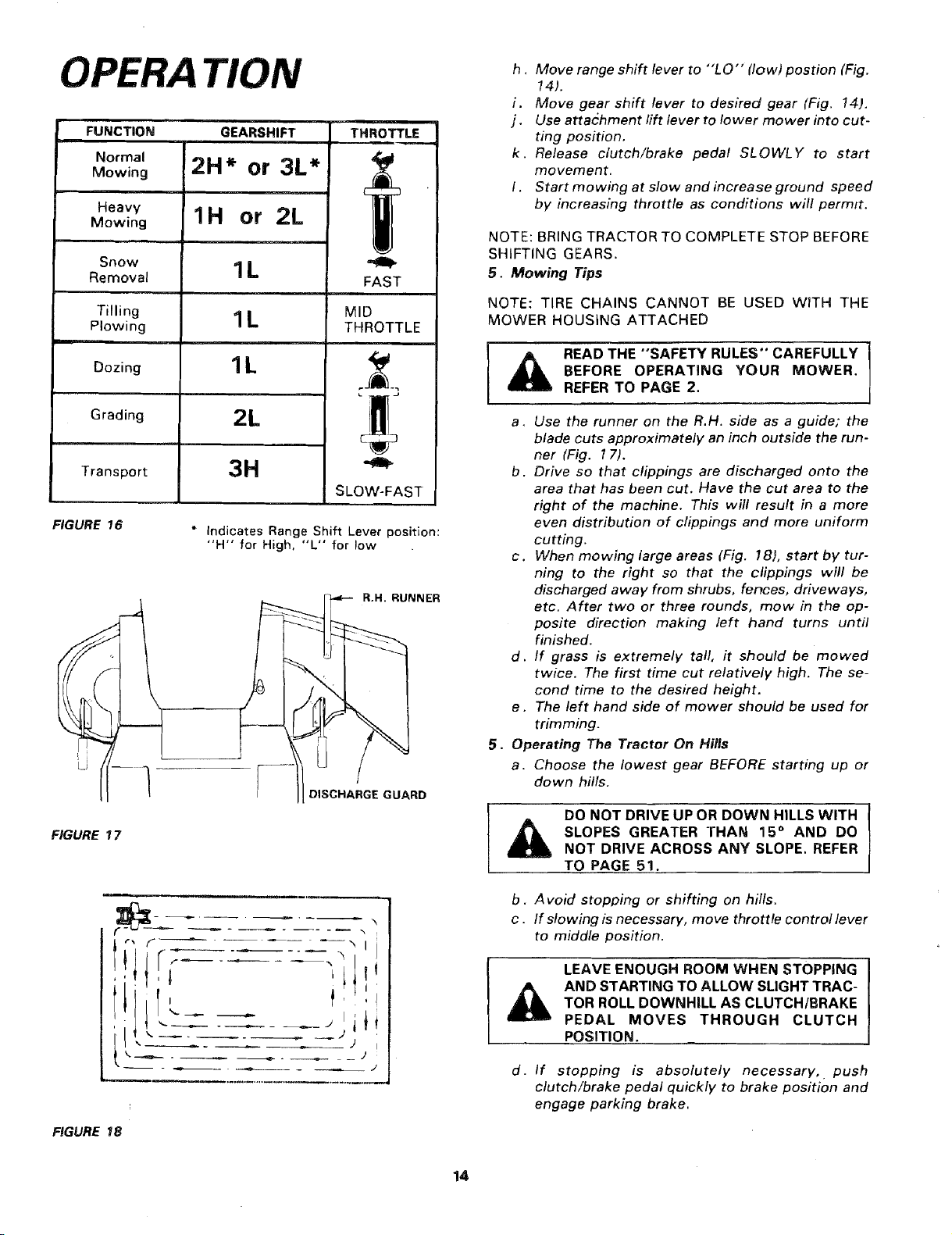
FUNCTION
Normal
Mowing
Heavy
Mowing
Snow
Removal
Tilling
Plowing
Dozing
Grading
Transport
FIGURE 16
Li
_GURE 17
GEARSHIFT THROTTLE
2H* or 3L*
1H or 2L
1L
1L
1L
2L
3H
* Indicates Range Shift Lever position:
"H" for High. "L" for low
CI
MID
THROTTLE
SLOW-FAST
R.H. RUNNER
DISCHARGE GUARD
h . Move range shift lever to "'LO'" (low) postion (Fig.
14).
i. Move gear shift lever to desired gear (Fig. 14).
j. Use attachment rift lever to lower mower into cut-
ting position.
k. Release clutch/brake pedal SLOWLY to start
movement.
I. Start mowing at slow and increase ground speed
by increasing throttle as conditions will permit.
NOTE: BRING TRACTOR TO COMPLETE STOP BEFORE
SHIFTING GEARS.
5. Mowing Tips
NOTE: TIRE CHAINS CANNOT BE USED WITH THE
MOWER HOUSING ATTACHED
READ THE "SAFETY RULES" CAREFULLY I
BEFORE OPERATING YOUR MOWER.
REFER TO PAGE 2.
a. Use the runner on the R.H. side as a guide; the
blade cuts approximately an inch outside the run-
ner (Fig. 17).
b. Drive so that clippings are discharged onto the
area that has been cut. Have the cut area to the
right of the machine. This will result in a more
even distribution of clippings and more uniform
cutting.
c. When mowing large areas (Fig. 18), start by tur-
ning to the right so that the clippings will be
discharged away from shrubs, fences, driveways,
etc. After two or three rounds, mow in the op-
posite direction making left hand turns until
finished.
d. If grass is extremely tall, it should be mowed
twice. The first time cut relatively high. The se-
cond time to the desired height.
e. The left hand side of mower should be used for
trimming.
5. Operating The Tractor On Hills
a. Choose the lowest gear BEFORE starting up or
down hills.
DO NOT DRIVE UP OR DOWN HILLS WITH
SLOPES GREATER THAN 15 ° AND DO
NOT DRIVE ACROSS ANY SLOPE, REFER
TO PAGE 51.
I
FIGURE 18
!t!
..... ,lil
' _, Jj
b. Avoid stopping or shifting on hills.
c . If slowing is necessary, move throttle control lever
to middle position.
LEAVE ENOUGH ROOM WHEN STOPPING
AND STARTING TO ALLOW SLIGHT TRAC-
TOR ROLL DOWNHILL AS CLUTCH/BRAKE
PEDAL MOVES THROUGH CLUTCH
POSITION.
d. If stopping is absolutely necessary, push
clutch/brake pedal quickly to brake position and
engage parking brake.
14
e. To restart your tractor, make sure tractor is in 1st
gear and that you have allowed room to roll slight-
ly downhill. Disengage parking brake and release
clutch/brake pedal SLOWLY to start tractor for-
ward movement.
f. Make all turns slowly.
MAINTENANCE
To keep your tractor running better,
longer, perform necessary service using
the following maintenance schedule:
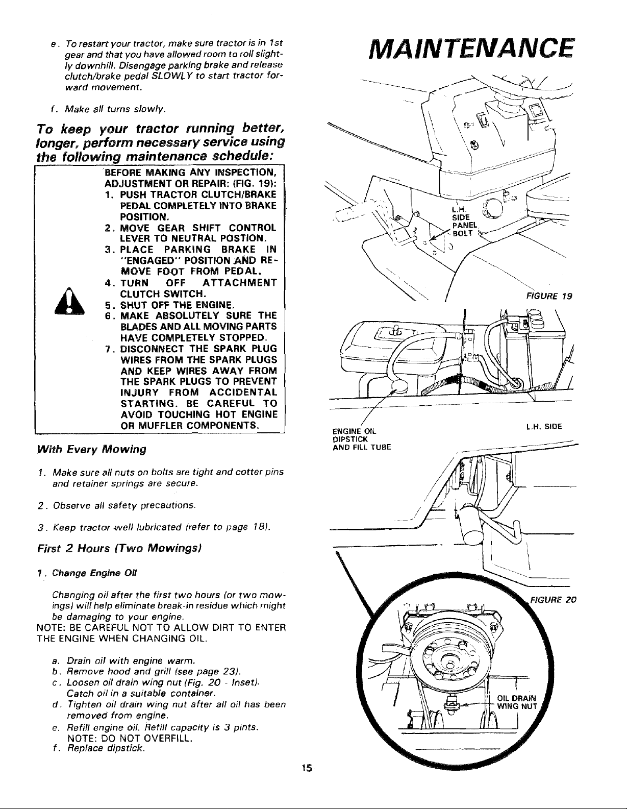
BEFORE MAKING ANY INSPECTION,
ADJUSTMENT OR REPAIR: (FIG. 19):
1. PUSH TRACTOR CLUTCH/BRAKE
PEDAL COMPLETELY INTO BRAKE
POSITION.
2. MOVE GEAR SHIFT CONTROL
LEVER TO NEUTRAL POSTION.
3. PLACE PARKING BRAKE IN
"ENGAGED" POSITION :AND RE-
MOVE FOOT FROM PEDAL,
4. TURN OFF ATTACHMENT
CLUTCH SWITCH.5. SHUT OFF THE ENGINE.
6. MAKE ABSOLUTELY SURE THE
BLADES AND ALL MOVING PARTS
HAVE COMPLETELY STOPPED.
7. DISCONNECT THE SPARK PLUG
WIRES FROM THE SPARK PLUGS
AND KEEP WIRES AWAY FROM
THE SPARK PLUGS TO PREVENT
INJURY FROM ACCIDENTAL
STARTING. BE CAREFUL TO
AVOID TOUCHING HOT ENGINE
OR MUFFLER COMPONENTS.
With Every Mowing
\
L,H.
SIDE
PANEL_
FIGURE 19
ENGINE OIL L.H. SIDE
DIPSTICK .
AND FILL TUBE .... _
I. Make sure all nuts on bolts are tight and cotter pins
and retainer springs are secure.
2. Observe all safety precautions.
3. Keep tractor _vell lubricated (refer to page !8).
First 2 Hours (Two Mowings)
1. Change Engine Oil
Changing off after the first two hours (or two mow-
ings) will help eliminate break-in residue which might
be damaging to your engine.
NOTE: BE CAREFUL NOT TO ALLOW DIRT TO ENTER
THE ENGINE WHEN CHANGING OIL.
a. Drain oil with engine warm.
b. Remove hood and grill (see page 23).
c. Loosen oil drain wing nut (Fig. 20 - Inset).
Catch oil in a suitable container.
d. Tighten oil drain wing nut after all oil has been
removed from engine.
e. Refill engine oil. Refill capacity is 3 pints.
NOTE: DO NOT OVERFILL.
f. Replace dipstick.
t
FIGURE 20
15
MAINTENANCE
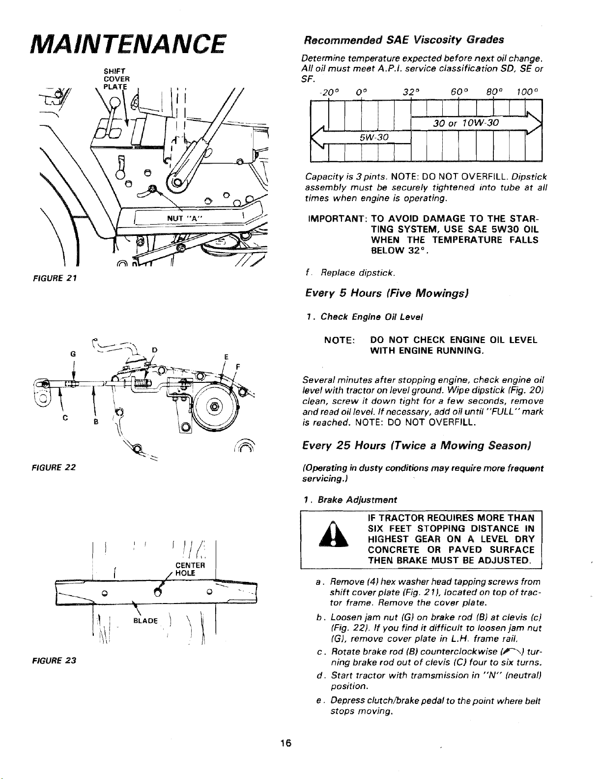
SHIFT
COVER
Recommended SAE Viscosity Grades
Determine temperature expected before next oft change.
All oft must meet A.P.I. service classification SD, SE or
SF.
_20 o 0 o 32 ° 60 ° 80 ° 100 °
30 or lOW-30 _;_
I IF]
\
FIGURE 21
G " E
D
Capacity is 3pints. NOTE: DO NOT OVERFILL. Dipstick
assembly must be securely tightened into tube at all
times when engine is operating.
IMPORTANT: TO AVOID DAMAGE TO THE STAR-
"rING SYSTEM, USE SAE 5W30 OIL
WHEN THE TEMPERATURE FALLS
BELOW 32 ° .
f Replace dipstick.
Every 5 Hours (l_ve Mowings)
1. Check Engine Oil Level
NOTE: DO NOT CHECK ENGINE OIL LEVEL
WITH ENGINE RUNNING.
Several minutes after stopping engine, check engine oft
level with tractor on level ground. Wipe dipstick (Fig. 20)
clean, screw ff down tight for a few seconds, remove
and read oft level. If necessary, add oil until "FULL" mark
is reached. NOTE: DO NOT OVERFILL.
Every 25 Hours (Twice a Mowing Season)
FIGURE 22
FIGURE 23
I i
CENTER
_ HOLE
,,,oE) \
i i
(Operating in dusty conditions may require more frequent
servicing.)
1. Brake Adjustment
IF TRACTOR REQUIRES MORE THAN
SIX FEET STOPPING DISTANCE IN
HIGHEST GEAR ON A LEVEL DRY
CONCRETE OR PAVED SURFACE
THEN BRAKE MUST BE ADJUSTED.
a . Remove (4) hex washer head tapping screws from
shift cover plate (Fig. 21), located on top of trac-
tor frame. Remove the cover plate.
b. Loosen jam nut (G) on brake rod (B) at clevis (c)
I
(Fig. 22). If you find it difficult to loosen jam nut
(G), remove cover plate in L.H. frame raft.
c. Rotate brake rod (B) counterclockwise (,#-_) tur-
ning brake rod out of clevis (C) four to six turns.
d. Start tractor with tramsmission in "N'" (neutral)
position.
e . Depress clutch/brake pedal to the point where belt
stops moving.
16
 Loading...